

SONY DCR TRV230 Diagram
DCR-TRV250
RMT-814
SERVICE MANUAL
Ver 1.2 2003. 03
Revision History
Revision History
M2200 MECHANISM
Link
Link
SPECIFICATIONS
SPECIFICATIONS
BLOCK DIAGRAMS
BLOCK DIAGRAMS
LEVEL 2
US Model
Canadian Model
E Model
Brazilian Model
Tourist Model
PRINTED WIRING BOARDS
PRINTED WIRING BOARDS
SERVICE NOTE
SERVICE NOTE
DISASSEMBLY
DISASSEMBLY
•For ADJUSTMENTS (SECTION 6), refer to SERVICE MANUAL, ADJ (987624151.pdf).
•For INSTRUCTION MANUAL, refer to SERVICE MANUAL, LEVEL1 (987624141.pdf).
•For MECHANISM ADJUSTMENTS, refer to the “8mm Video MECHANICAL ADJUSTMENT MANUAL IX
M2000 MECHANISM ” (9-929-861-11).
• Reference No. search on printed wiring boards is available.
•When the machine needs to be repaired, make sure to follow the items of “CCD TYPE CHECK” and “LCD
TYPE CHECK”.
• HELP: Sheet attachment positions and procedures of processing the flexible boards/harnesses are shown.
On the VC-305 board
This service manual provides the information that is premised the circuit board replacement service and not intended repair
inside the VC-305 board.
Therefore, schematic diagram, printed wiring board, waveforms, mounted parts location and electrical parts list of the VC-305
board are not shown.
The following pages are not shown.
Schematic diagram .............................Pages 4-9 to 4-48
Printed wiring board............................Pages 4-67 to 4-70
Waveforms...........................................
FRAME SCHEMATIC DIAGRAMS
FRAME SCHEMATIC DIAGRAMS
SCHEMATIC DIAGRAMS
SCHEMATIC DIAGRAMS
Mounted parts location ..................
Electrical parts list.........................Pages 5-18 to 5-25
Page 4-82 to 4-85
REPAIR PARTS LIST
REPAIR PARTS LIST
Page 4-88, 4-89
DIGITAL VIDEO CAMERA RECORDER
DCR-TRV250
COVER
COVER
SPECIFICATIONS
TM
SERIES
Video camera
recorder
System
Video recording system
2 rotary heads
Helical scanning system
Audio recording system
Rotary heads, PCM system
Quantization: 12 bits (Fs 32 kHz,
stereo 1, stereo 2), 16 bits
(Fs 48 kHz, stereo)
Video signal
NTSC color, EIA standards
Usable cassette
8 mm video format cassette
Recording/playback time
(using 120 min. Hi8/Digital8 video
cassette)
SP mode: 1 hour
LP mode: 1 hour and 30 minutes
Fastforward/rewind time
(using 120 min. Hi8/Digital8 video
cassette)
Approx. 5 min.
Viewfinder
Electric Viewfinder (monochrome)
Image device
3 mm (1/6 type) CCD
(Charge Coupled Device)
Gross: Approx. 460 000 pixels
Effective: Approx. 290 000 pixels
Lens
Combined power zoom lens
Filter diameter 37 mm (1 7/16 in.)
20× (Optical), 700×
Focal length
f=2.5 – 50 mm (1/8 - 2 in.)
When converted to a 35 mm
still camera
f=42 – 840 mm (1 11/16 - 33 1/8 in.)
Colour temperature
Auto
Minimum illumination
4 lx (lux) (F 1.6)
0 lx (lux) (in the NightShot mode)*
*Objects unable to be seen due to
the dark can be shot with infrared
lighting.
Input/output
connectors
S
video jack
Output
4-pin mini DIN
Luminance signal: 1 Vp-p,
75 Ω (ohms), unbalanced
Chrominance signal: 0.286 Vp-p,
75 Ω (ohms), unbalanced
Audio/Video
Output
AV MINIJACK,
VIDEO:
1 Vp-p, 75 Ω (ohms),
unbalanced, sync negative
AUDIO:
327 mV, (at output impedance more
than 47 kΩ (kilohms))
Output impedance with less than
2.2 kΩ (kilohms)
Stereo minijack (ø 3.5 mm)
jack
(Digital)
DV jack
Input/Output
4-pin connector
USB jack
Mini-B
LCD screen
Picture
6.2 cm (2.5 type)
50.3 × 37.4 mm
(2 × 1 1/2 in.)
Total dot number
123 200 (560 × 220)
General
Power requirements
7.2 V (Recahrgeable battery pack)
8.4 V (AC adaptor)
Average power consumption
(when using the battery pack)
During camera recording using
LCD
3.5 W
Viewfinder
2.7 W
Operating temperature
0 °C to 40 °C (32 °F to 104 °F)
Recommended charging
temperature
10 °C to 30 °C (50 °F to 86 °F)
Storage temperature
–20 °C to +60 °C (–4 °F to +140 °F)
Dimensions (approx.)
89 × 101 × 199 mm
(3 5/8 × 4 × 7 7/8 in.) (w/h/d)
Mass (approx.)
810 g (1 lb 12 oz)
main unit only
950 g (2 lb 1 oz)
including the rechargeable battery
pack NP-FM30, Hi8/Digital8 cassette,
lens cap and shoulder strap
AC adaptor
Power requirements
100 - 240 V AC, 50/60 Hz
Current consumption
0.35 – 0.18 A
Power consumption
18 W
Output voltage
DC OUT: 8.4 V, 1.5 A in the
operating mode
Operating temperature
0 °C to 40 °C (32 °F to 104 °F)
Storage temperature
–20 °C to +60 °C (–4 °F to +140 °F)
Dimensions (approx.)
56 × 31 × 100 mm
(2 1/4 × 1 1/4 × 4 in.) (w/h/d)
excluding projecting parts
Mass (approx.)
190 g (6.7 oz)
excluding power cord
Recargeable
battery pack
Maximum output voltage
DC 8.4 V
Output voltage
DC 7.2 V
Capacity
5.0 Wh (700 mAh)
Operating temperature
0 °C to 40 °C (32 °F to 104 °F)
Dimensions (approx.)
38.2 × 20.5 × 55.6 mm
(1 9/16 × 13/16 × 2 1/4 in.)
(w/h/d)
Mass (approx.)
65 g (2.3 oz)
Type
Lithium ion
— 2 —
Design and specifications are
subject to change without notice.
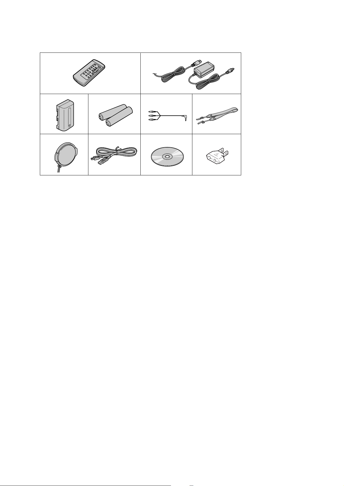
Supplied accessories
DCR-TRV250
1
3
7
1 Wireless Remote Commander (1)
2 AC-L15A/L15B AC Adaptor (1), Power
cord (1)
3 NP-FM30 Rechargeable Battery Pack
(1)
4 Size AA (R6) battery for Remote
Commander (2)
4
890
2
65
5 A/V connecting cable (1)
6 Shoulder strap (1)
7 Lens cap (1)
8 USB cable (1)
9 CD-ROM (SPVD-010 USB Driver)
0 2-pin conversion adaptor (1) (E, JE)
(1)
— 3 —

DCR-TRV250
SAFETY-RELATED COMPONENT WARNING!!
COMPONENTS IDENTIFIED BY MARK 0 OR DOTTED LINE WITH
MARK 0 ON THE SCHEMATIC DIAGRAMS AND IN THE PARTS
LIST ARE CRITICAL TO SAFE OPERATION. REPLACE THESE
COMPONENTS WITH SONY PARTS WHOSE PART NUMBERS
APPEAR AS SHOWN IN THIS MANUAL OR IN SUPPLEMENTS
PUBLISHED BY SONY.
SAFETY CHECK-OUT
After correcting the original service problem, perform the following
safety checks before releasing the set to the customer.
1. Check the area of your repair for unsoldered or poorly-soldered
connections. Check the entire board surface for solder splashes
and bridges.
2. Check the interboard wiring to ensure that no wires are
"pinched" or contact high-wattage resistors.
3. Look for unauthorized replacement parts, particularly
transistors, that were installed during a previous repair . Point
them out to the customer and recommend their replacement.
4. Look for parts which, through functioning, show obvious signs
of deterioration. Point them out to the customer and
recommend their replacement.
5. Check the B+ voltage to see it is at the values specified.
6. Flexible Circuit Board Repairing
•Keep the temperature of the soldering iron around 270˚C
during repairing.
• Do not touch the soldering iron on the same conductor of the
circuit board (within 3 times).
• Be careful not to apply force on the conductor when soldering
or unsoldering.
ATTENTION AU COMPOSANT AYANT RAPPORT
À LA SÉCURITÉ!
LES COMPOSANTS IDENTIFÉS P AR UNE MARQUE 0 SUR LES
DIAGRAMMES SCHÉMA TIQUES ET LA LISTE DES PIÈCES SONT
CRITIQUES POUR LA SÉCURITÉ DE FONCTIONNEMENT. NE
REMPLACER CES COMPOSANTS QUE PAR DES PIÈSES SONY
DONT LES NUMÉROS SONT DONNÉS DANS CE MANUEL OU
DANS LES SUPPÉMENTS PUBLIÉS PAR SONY.
Unleaded solder
Boards requiring use of unleaded solder are printed with the leadfree mark (LF) indicating the solder contains no lead.
(Caution: Some printed circuit boards may not come printed with
the lead free mark due to their particular size.)
: LEAD FREE MARK
Unleaded solder has the following characteristics.
• Unleaded solder melts at a temperature about 40°C higher than
ordinary solder.
Ordinary soldering irons can be used but the iron tip has to be
applied to the solder joint for a slightly longer time.
Soldering irons using a temperature regulator should be set to
about 350°C.
Caution: The printed pattern (copper foil) may peel away if the
heated tip is applied for too long, so be careful!
• Strong viscosity
Unleaded solder is more viscous (sticky, less prone to flow) than
ordinary solder so use caution not to let solder bridges occur such
as on IC pins, etc.
• Usable with ordinary solder
It is best to use only unleaded solder but unleaded solder may
also be added to ordinary solder.
— 4 —

Ver 1.2 2003.03
DCR-TRV250
TABLE OF CONTENTS
Section Title Page Section Title Page
1. SERVICE NOTE
1-1. Note for Repair ································································1-1
1-2. Power Supply During Repairs ·········································1-1
1-3. To Take Out a Cassette when not Eject (Force Eject) ·····1-2
1-4. Jig Modification ······························································1-3
1-5. CCD Type Check·····························································1-4
1-5-1.Checking Method by Serial No. ······································1-4
1-5-2.Checking Method by Voltage ··········································1-4
1-6. LCD Type Check·····························································1-4
1-7. Self-diagnosis Function ···················································1-5
1-7-1.Self-diagnosis Function ···················································1-5
1-7-2.Self-diagnosis Display·····················································1-5
1-7-3.Service Mode Display ·····················································1-5
1-7-4.Self-diagnosis Code Table ···············································1-6
2. DISASSEMBLY
Connection of Equipment················································2-2
2-1. Video Light······································································2-3
2-2. PD-180 Board··································································2-4
2-3. LCD Module····································································2-5
Service Position to Check PD-180 Board ·······················2-5
2-4. Control Switch Block (PR-3000) ····································2-6
2-5. VF Lens (B) Assembly···················································· 2-7
2-6. LB-083 Board··································································2-8
Service Position to Check LB-083 Board ·······················2-8
2-7. Cabinet (L) Assembly······················································2-9
2-8. F Panel Block Assembly················································ 2-10
Service Position to Check SI-035 Board ·······················2-11
2-9. SI-035 Board ································································· 2-12
2-10. Front Ring······································································2-12
2-11. Cabinet (R) Block Assembly ·········································2-13
Service Position to Check the Camera Section ·············2-13
2-12. Control Switch Block (CF-3000) ··································2-14
2-13. Hinge Assembly ····························································2-15
2-14. Control Switch Block (FK-3000) ··································2-16
2-15. EVF Block Assembly ····················································2-16
Service Position to Check VC-305 Board (Side A) ·······2-17
2-16. Battery Panel Block Assembly ······································ 2-18
2-17. Control Switch Block (SS-3000) ···································2-19
2-18. Lens Block Assembly ····················································2-19
2-19. FP-577 Flexible Board ··················································2-20
2-20. Cabinet (L) Section ·······················································2-21
2-21. VC-305 Board ·······························································2-21
Service Position to Check VC-305 Board (Side B)·······2-22
Service Position to Check the Mechanism Deck···········2-23
2-22. Mechanism Deck Block ················································2-24
2-23. Circuit Boards Location ················································2-25
2-24. Flexible Boards Location ··············································2-26
4. PRINTED WIRING BOARDS AND
SCHEMATIC DIAGRAMS
4-1. Frame Schematic Diagrams
Frame Schematic Diagram (1/2) ·····································4-1
Frame Schematic Diagram (2/2) ·····································4-3
4-2. Schematic Diagrams························································4-5
CD-418 (CCD IMAGER)················································4-7
PD-180 (1/2)
(RGB DRIVE, TIMING GENERATOR)······················ 4-49
PD-180 (2/2) (BACKLIGHT DRIVE) ··························4-51
LB-083 (EVF, EVF BACKLIGHT) ······························4-53
SI-035 (STEADYSHOT, MIC), FP-569 FLEXIBLE····4-55
FP-577 FLEXIBLE ·······················································4-57
LS-057 (S/T REEL SENSOR), FP-228, FP-299,
FP-300, FP-301, FP-302 FLEXIBLE···························· 4-58
CF-3000, FK-3000 (CONTROL SWITCH BLOCK) ···4-59
SS-3000, PR-3000 (CONTROL SWITCH BLOCK)····4-61
4-3. Printed Wiring Boards ···················································4-63
CD-418 ·········································································· 4-65
PD-180···········································································4-71
LB-083···········································································4-75
SI-035 ············································································ 4-77
LS-057, FP-228, FP-299, FP-300, FP-301,
FP-302, FP-569, FP-577 FLEXIBLE···························· 4-79
4-4. Waveforms ·····································································4-81
4-5. Mounted Parts Location ················································ 4-90
5. REPAIR PARTS LIST
5-1. Exploded Vie ws ····························································5-2
5-1-1. Overall Assembly··························································5-2
5-1-2. F Panel Block Assembly ···············································5-3
5-1-3. Lens Block Assembly ···················································5-4
5-1-4. LCD Block Assembly ···················································5-5
5-1-5. Cabinet (R) Block Assembly ········································5-6
5-1-6. EVF Block Assembly····················································5-7
5-1-7. Battery Panel Block Assembly······································5-8
5-1-8. MD Frame Block ··························································5-9
5-1-9. Cassette Compartment Assembly, Drum Assembly ···5-10
5-1-10. LS Chassis Block Assembly ·······································5-11
5-1-11. Mechanical Chassis Block Assembly-1 ······················5-12
5-1-12. Mechanical Chassis Block Assembly-2 ······················5-13
5-2. Electrical Parts List ·····················································5-14
3. BLOCK DIAGRAMS
3-1. Overall Block Diagram (1/5)···········································3-1
3-2. Overall Block Diagram (2/5)···········································3-3
3-3. Overall Block Diagram (3/5)···········································3-5
3-4. Overall Block Diagram (4/5)···········································3-7
3-5. Overall Block Diagram (5/5)···········································3-9
3-6. Power Block Diagram (1/3)···········································3-11
3-7. Power Block Diagram (2/3)···········································3-13
3-8. Power Block Diagram (3/3)···········································3-15
— 5 —
DCR-TRV250
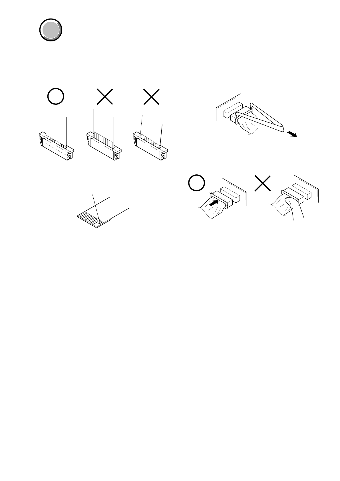
When installing a connector, don’t press down at wire of connector.
It is possible that a wire is snapped.
COVER
COVER
SECTION 1
SERVICE NOTE
1-1. NOTE FOR REPAIR
Make sure that the flat cable and flexible board are not cracked of
bent at the terminal.
Do not insert the cable insufficiently nor crookedly.
Cut and remove the part of gilt
which comes off at the point.
(Be careful or some
pieces of gilt may be left inside)
When remove a connector, don’t pull at wire of connector.
It is possible that a wire is snapped.
1-2. POWER SUPPLY DURING REPAIRS
In this unit, about 10 seconds after power is supplied to the battery terminal using the regulated power supply (8.4V), the po wer is shut of f so
that the unit cannot operate.
The following method is available to prevent this.
Method 1.
Use the AC power adaptor (AC-L10, AC-VQ800 etc.).
1-1
DCR-TRV250
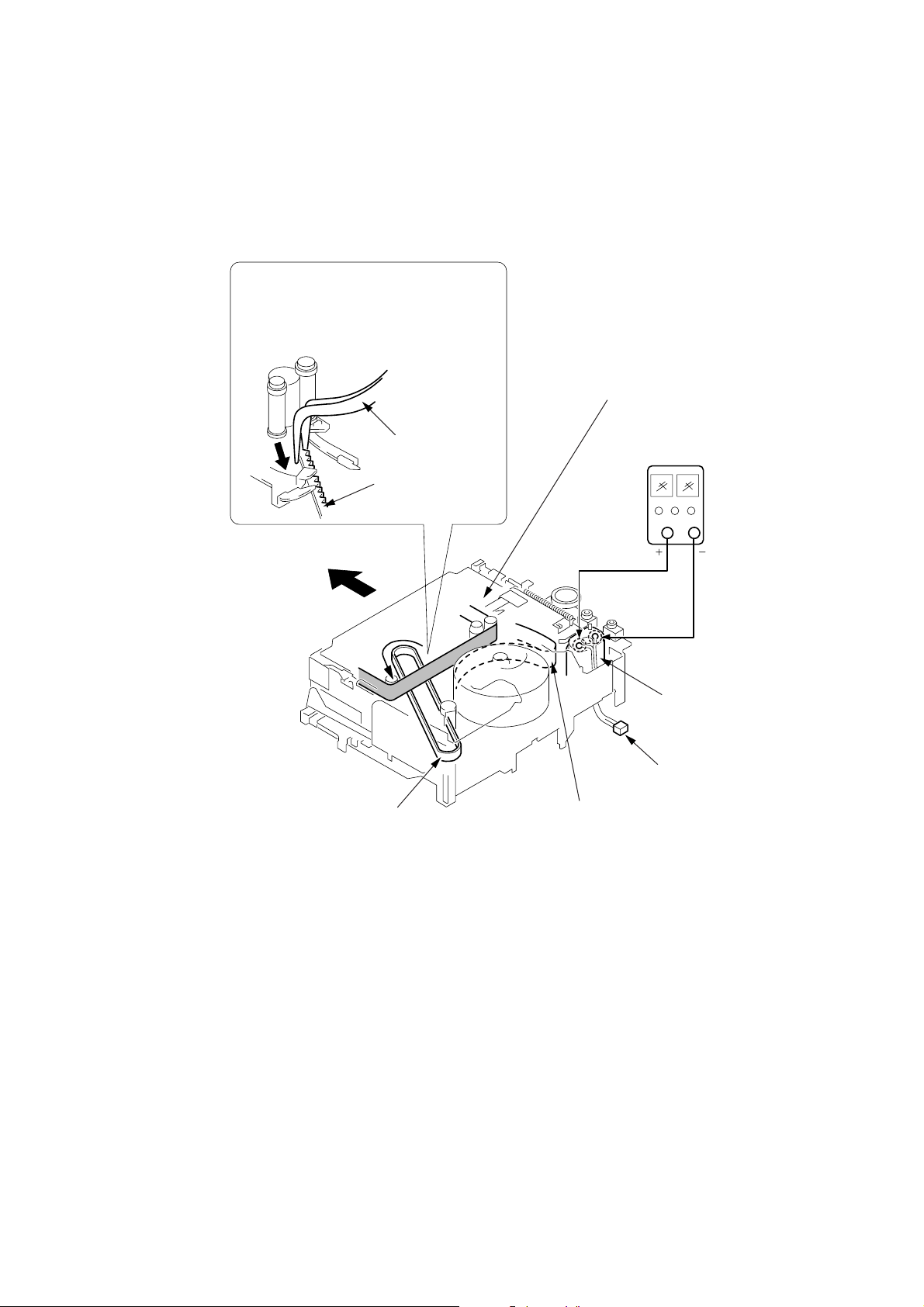
1-3. TO TAKE OUT A CASSETTE WHEN NOT EJECT (FORCE EJECT)
1 Refer to “SECTION 2 DISASSEMBLY” to remove the mechanism deck block.
2 Disconnect CN2401 (2P) of VC-305 board.
3 Add +5V from the DC POWER SUPPLY and unload with a pressing the cassette compartment.
4 Pull the timing belt in the direction of
arrow A with a pincette while pressing
the cassette compartment (take care
not to damage) to adjust the bending
of a tape.
Press the cassette compartment not to
rise the cassette compartment
5 Let go your hold the cassette
compartment and rise the cassette
compartment to take out a cassette.
A
Timing belt
A
Timing belt
Pincette
[DC power supply]
(+5V)
Loading motor
Disconnect CN2401
of VC-305 board.
Adjust the bending of a tape
1-2
DCR-TRV250
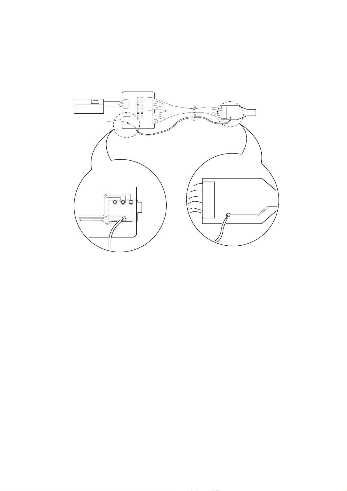
1-4. JIG MODIFICATION
Connect the LANC SIG pin of the I/F unit for LANC control to the land of pin 1 of the CPC jig connector with a jumper wire.
This modification is required in the DCR-TRV250 only. Be sure to disconnect the jumper wire when using the I/F unit for LANC control or
CPC jig connector on other models.
I/F unit for LANC control
(J-6082-521-A)
LANC jack
CPC jig connector
(J-6082-539-A)
The other side
LANC
jack
CN1
1
CX2000
1-3
DCR-TRV250
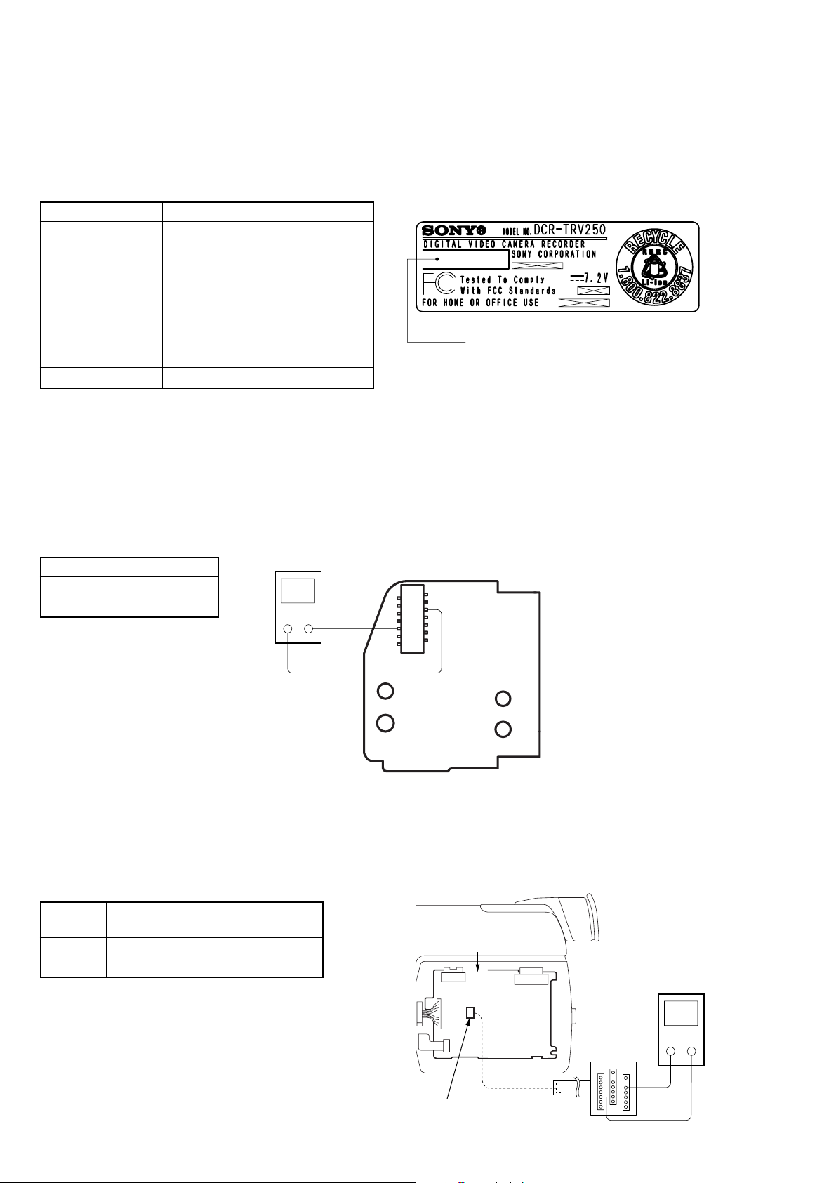
1-5. CCD TYPE CHECK
Note: About VC-304/VC-305 board and CCD imager, discriminate CCD type on the machine, and replace same type.
1-5-1. Checking Method by Serial No.
Type of CCD imager can be identified with its serial No.. Check the serial No. printed on the MODEL NUMBER LABEL.
Ver 1.2 2003.03
Serial No. CCD type VC board
MODEL NUMBER LABEL
310001 to 310300,
320071 to 341220,
341521 to 341720,
342421 to 342720,
820001 to 821100,
TYPE SO VC-305 (TYPE SO)
850001 to 854200,
860001 to 863400,
940001 to 940600
Serial No.
1320001 to 1333500 TYPE PA VC-305 (TYPE PA)
other numbers TYPE SO VC-304 (TYPE SO) *1
*1: For VC-304 board, refer to the SERVICE MANUAL, LEVEL 2 SUPPLEMENT-1.
1-5-2. Checking Method by Voltage
Checking method:
1) Refer to “SECTION 2 DISASSEMBLY” to remove the cabinet (R) block.
2) Set the POWER switch to CAMERA.
3) By measuring the voltage between Pin 5 (CAM_15V/12V) to Pin 0 (GND) of CN951 on CD-418 board, the type of CCD imager can
be discriminated.
Voltage CCD type
12V TYPE PA
15V TYPE SO
Digital voltmeter
+—
5 pin
q; pin
CD-418 BOARD
14
13
2
1
CN951
1-6. LCD TYPE CHECK
By measuring the resistor value between Pin 6 of CN5502 and Pin 0 of CN5502 on PD-180 board, the type of LCD can be discriminated.
Note: About PD-180 board and LCD module, discriminate LCD type on the machine, and replace the same type.
PD-180 board CN5502
Resistor
value
2.2 kΩ TYPE S PD-180 (TYPE S)
3.3 kΩ TYPE C PD-180 (TYPE C)
LCD type PD board
1-4
PD-180 board
CN5502
Multi CPC jig
(J-6082-311-A)
Volt ohm meter
+
—
6 pin
0 pin
1-7. SELF-DIAGNOSIS FUNCTION
DCR-TRV250
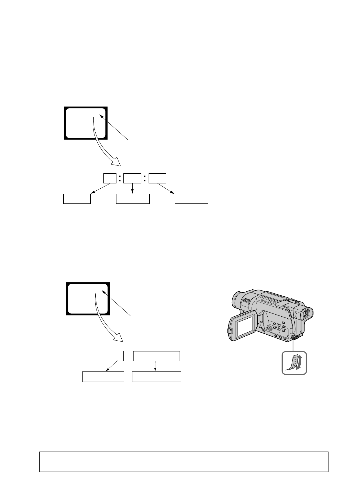
1-7-1. Self-diagnosis Function
When problems occur while the unit is operating, the self-diagnosis
function starts working, and displays on the viewfinder or LCD what
to do. This function consists of two display; self-diagnosis display
and service mode display.
Details of the self-diagnosis functions are provided in the Instruction
manual.
Viewfinder or LCD
C : 3 1 : 1 1
Blinks at 3.2Hz
1 1
Refer to “1-7-4. Self-diagnosis Code Table”.
Repaired by:
C : Corrected by customer
H : Corrected by dealer
E : Corrected by service
engineer
3 1C
Block
Indicates the appropriate
step to be taken.
E.g.
31 ....Reload the tape.
32 ....Turn on power again.
1-7-2. Self-diagnosis Display
When problems occur while the unit is operating, the counter of the
viewfinder or LCD shows a 4-digit display consisting of an alphabet
and numbers, which blinks at 3.2 Hz. This 5-character display
indicates the “repaired by:”, “block” in which the problem occurred,
and “detailed code” of the problem.
Detailed Code
1-7-3. Service Mode Display
The service mode display shows up to six self-diagnosis codes shown in the past.
1. Display Method
While pressing the “STOP” key, set the switch from OFF to “VCR”, and continue pressing the “STOP” key for 5 seconds continuously. The
service mode will be displayed, and the counter will show the backup No. and the 5-character self-diagnosis codes.
Viewfinder or LCD
[3] C : 3 1 : 1 1
Lights up
[3]
Backup No.
Order of previous errors
C : 3 1 : 1 1
Self-diagnosis Codes
Control dial
2. Switching of Backup No.
By rotating the control dial, past self-diagnosis codes will be shown in order. The backup No. in the [] indicates the order in which the
problem occurred. (If the number of problems which occurred is less than 6, only the number of problems which occurred will be shown.)
[1] : Occurred first time [3] : Occurred third time [5] : Occurred fifth time
[2] : Occurred second time [4] : Occurred fourth time [6] : Occurred the last time
3. End of Display
Turning OFF the power supply will end the service mode display.
Note: The “self-diagnosis display” data will be backed up by the lithium battery (CONTROL SWITCH BLOCK (CF-3000):
BT001). When removing the cabinet (R) (removing the VC-305 board CN1007), the “self-diagnosis display” data will
be lost by initialization.
1-5
DCR-TRV250
1-7-4. Self-diagnosis Code Table
Self-diagnosis Code
Repaired by:
C
C
C
C
C
C
C
C
C
C
C
C
C
C
C
C
C
C
C
C
C
C
C
C
C
C
C
C
C
Block
Function
04
21
22
31
31
31
31
31
31
31
31
31
31
31
31
31
32
32
32
32
32
32
32
32
32
32
32
32
32
Detailed
Code
00
00
00
10
11
20
21
22
23
30
31
40
41
42
43
44
10
11
20
21
22
23
30
31
40
41
42
43
44
Symptom/State
Non-standard battery is used.
Condensation.
Video head is dirty.
LOAD direction. Loading does not
complete within specified time
UNLOAD direction. Loading does not
complete within specified time
T reel side tape slacking when unloading
S reel
side tape slacking when unloading
T reel fault.
S reel fault.
FG fault when starting capstan.
FG fault during normal capstan operations.
FG fault when starting drum.
PG fault when starting drum.
FG fault during normal drum operations.
PG fault during normal drum operations.
Phase fault during normal drum operations.
LOAD direction loading motor time-
out.
UNLOAD direction loading motor
time-out.
T reel side tape slacking when
unloading.
S reel side tape slacking when
unloading.
T reel fault.
S reel fault.
FG fault when starting capstan.
FG fault during normal capstan
operations.
FG fault when starting drum.
PG fault when starting drum.
FG fault during normal drum
operations.
PG fault during normal drum
operations.
Phase fault during normal drum
operations.
Correction
Use the InfoLITHIUM battery.
Remove the cassette, and insert it again after one hour.
Clean with the optional cleaning cassette.
Load the tape again, and perform operations from the beginning.
Load the tape again, and perform operations from the beginning.
.
Load the tape again, and perform operations from the beginning.
.
Load the tape again, and perform operations from the beginning.
Load the tape again, and perform operations from the beginning.
Load the tape again, and perform operations from the beginning.
Load the tape again, and perform operations from the beginning.
Load the tape again, and perform operations from the beginning.
Load the tape again, and perform operations from the beginning.
Load the tape again, and perform operations from the beginning.
Load the tape again, and perform operations from the beginning.
Load the tape again, and perform operations from the beginning.
Load the tape again, and perform operations from the beginning.
Remove the battery or power cable, connect, and perform
operations from the beginning.
Remove the battery or power cable, connect, and perform
operations from the beginning.
Remove the battery or power cable, connect, and perform
operations from the beginning.
Remove the battery or power cable, connect, and perform
operations from the beginning.
Remove the battery or power cable, connect, and perform
operations from the beginning.
Remove the battery or power cable, connect, and perform
operations from the beginning.
Remove the battery or power cable, connect, and perform
operations from the beginning.
Remove the battery or power cable, connect, and perform
operations from the beginning.
Remove the battery or power cable, connect, and perform
operations from the beginning.
Remove the battery or power cable, connect, and perform
operations from the beginning.
Remove the battery or power cable, connect, and perform
operations from the beginning.
Remove the battery or power cable, connect, and perform
operations from the beginning.
Remove the battery or power cable, connect, and perform
operations from the beginning.
1-6

Self-diagnosis Code
DCR-TRV250
Repaired by:
E
E
E
E
Block
Function
61
61
62
62
Detailed
Code
00
10
00
01
Symptom/State
Difficult to adjust focus
(Cannot initialize focus.)
Zoom operations fault
(Cannot initialize zoom lens.)
Steadyshot function does not work well.
(With pitch angular velocity sensor output
stopped.)
Steadyshot function does not work well.
(With yaw angular velocity sensor output
stopped.)
Correction
Inspect the lens block focus reset sensor (Pin qs of CN1551 of
VC-305 board) when focusing is performed when the control dial
is rotated in the focus manual mode and the focus motor drive circuit
(IC1554 of VC-305 board) when the focusing is not performed.
Inspect the lens block zoom reset sensor (Pin qg of CN1551 of
VC-305 board) when zooming is performed when the zoom switch
is operated and the zoom motor drive circuit (IC1554 of VC-305
board) when zooming is not performed.
Inspect pitch angular velocity sensor (SE751 of SI-035 board)
peripheral circuits.
Inspect yaw angular velocity sensor (SE752 of SI-035 board)
peripheral circuits.
1-7E
DCR-TRV250
COVER
COVER
SECTION 2
DISASSEMBLY
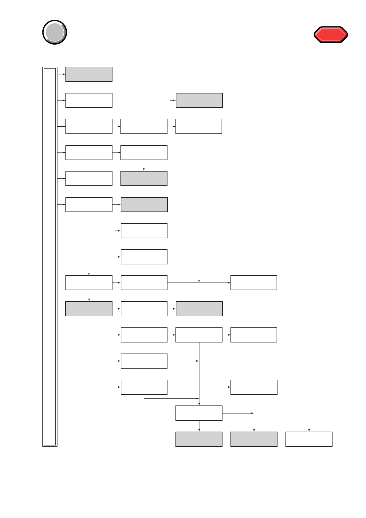
The following flow chart shows the disassembly procedure.
CONNECTION OF
EQUIPMENT
(Page 2-2)
2-1. VIDEO LIGHT
(Page 2-3)
2-2. PD-180 BOARD
(Page 2-4)
2-5. VF LENS (B)
ASSEMBLY
(Page 2-7)
2-7. CABINET (L)
ASSEMBLY
(Page 2-9)
2-8. F PANEL BLOCK
ASSEMBLY
(Page 2-10)
2-3. LCD MODULE
(Page 2-5)
2-6. LB-083
(Page 2-8)
SERVICE POSITION TO
CHECK LB-083 BOARD
(Page 2-8)
SERVICE POSITION TO
CHECK SI-035 BOARD
(Page 2-11)
SERVICE POSITION TO
CHECK PD-180 BOARD
2-4. CONTROL SWITCH
(Page 2-5)
BLOCK (PR-3000)
(Page 2-6)
HELP
HELP
DCR-TRV250
2-11. CABINET (R)
SERVICE POSITION TO
CHECK THE CAMERA
BLOCK ASSEMBLY
(Page 2-13)
SECTION (Page 2-13)
2-9. SI-035 BOARD
(Page 2-12)
2-10. FRONT RING
(Page 2-12)
2-12. CONTROL SWITCH
BLOCK (CF-3000)
(Page 2-14)
2-14. CONTROL SWITCH
BLOCK (FK-3000)
(Page 2-16)
2-15. EVF BLOCK
ASSEMBLY
(Page 2-16)
2-18. LENS BLOCK
ASSEMBLY
(Page 2-19)
2-19. FP-577 FLEXIBLE
BOARD
(Page 2-20)
SERVICE POSITION TO
CHECK VC-305 BOARD
(SIDE A) (Page 2-17)
2-16. BATTERY PANEL
BLOCK ASSEMBLY
(Page 2-18)
2-13. HINGE
ASSEMBLY
(Page 2-15)
2-17. CONTROL SWITCH
BLOCK (SS-3000)
(Page 2-19)
2-20. CABINET (L)
SECTION
(Page 2-21)
2-21. VC-305 BOARD
(Page 2-21)
SERVICE POSITION TO
CHECK VC-305 BOARD
(SIDE B) (Page 2-22)
2-1
SERVICE POSITION TO
CHECK THE MECHANISM
DECK (Page 2-23)
2-22. MECHANISM
DECK BLOCK
(Page 2-24)
DCR-TRV250
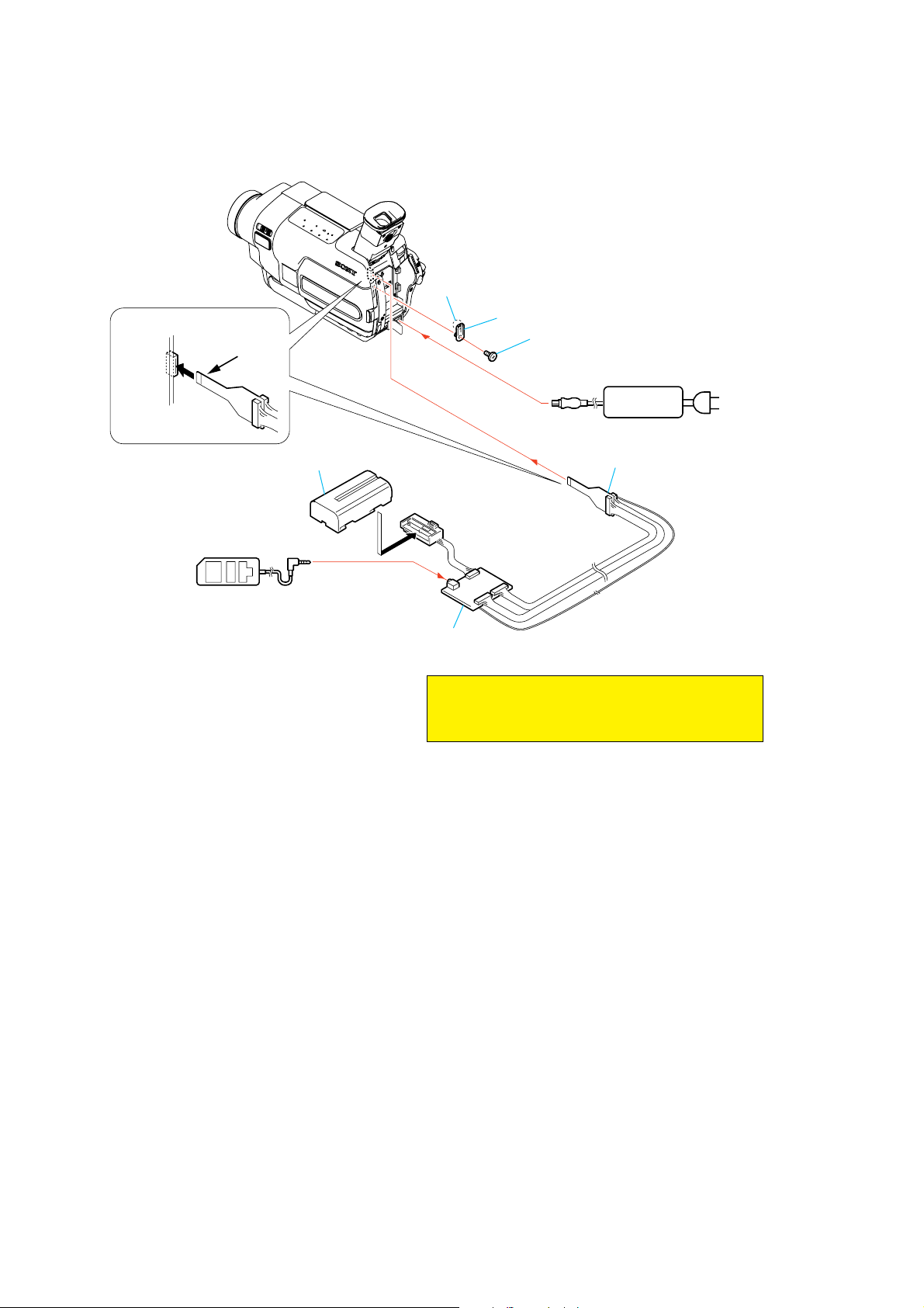
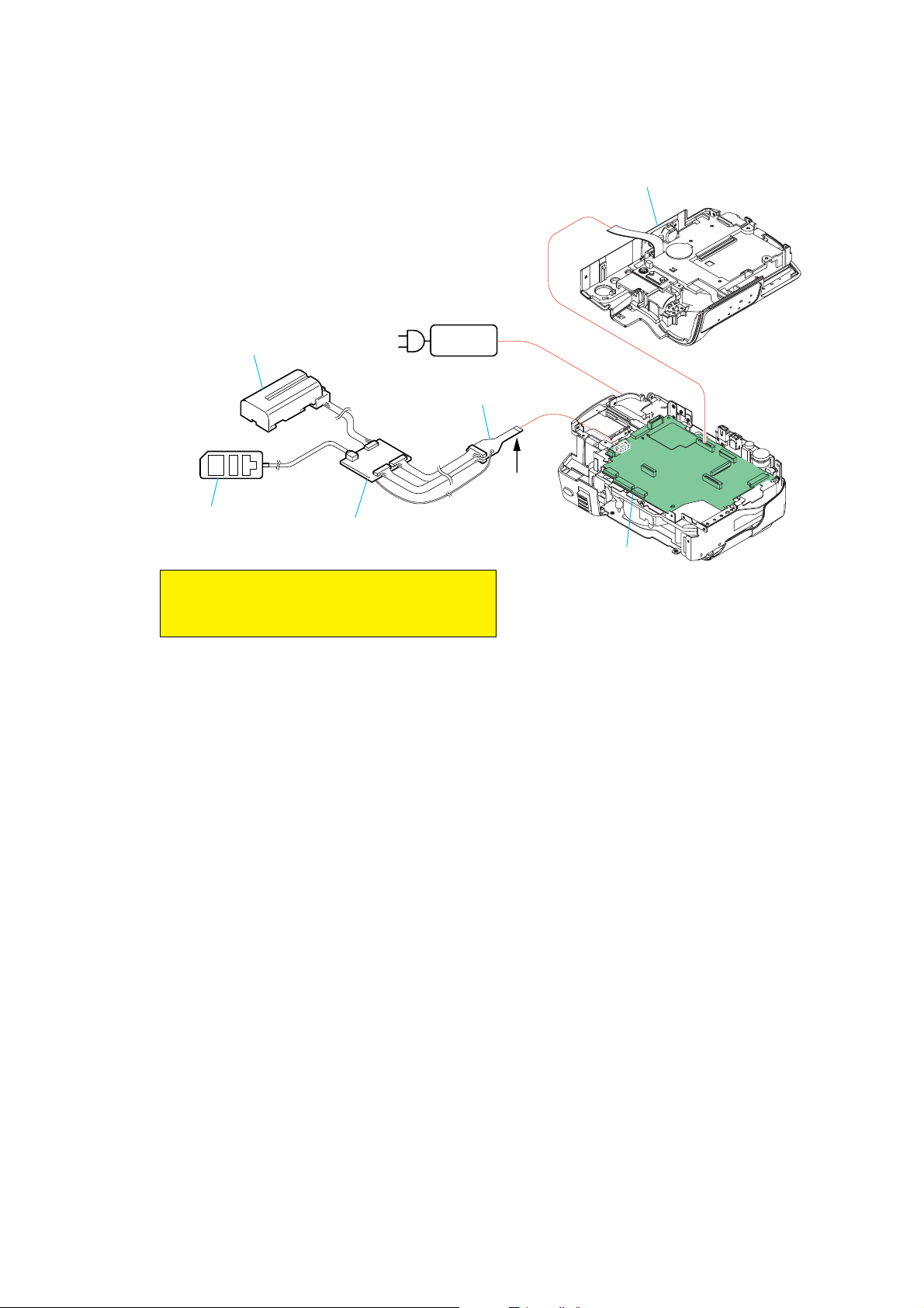
[CONNECTION OF EQUIPMENT]
Claw
CPC jig connector
CN1011
1
Conductor side
16
Info lithium battery
(L series)
Adjustment remote
commander (RM-95)
CPC lid
Screw
(M2)
AC power
adaptor
CPC jig connector
(J-6082-539-A) (Note)
I/F unit for LANC control
(J-6082-521-A) (Note)
Note : The "Jig Modification" is necessary for connecting
the adjusting remote commander to this set.
Modify the jig by referring to page 1-3.
2-2
Note: Follow the disassembly procedure in the numerical order given.
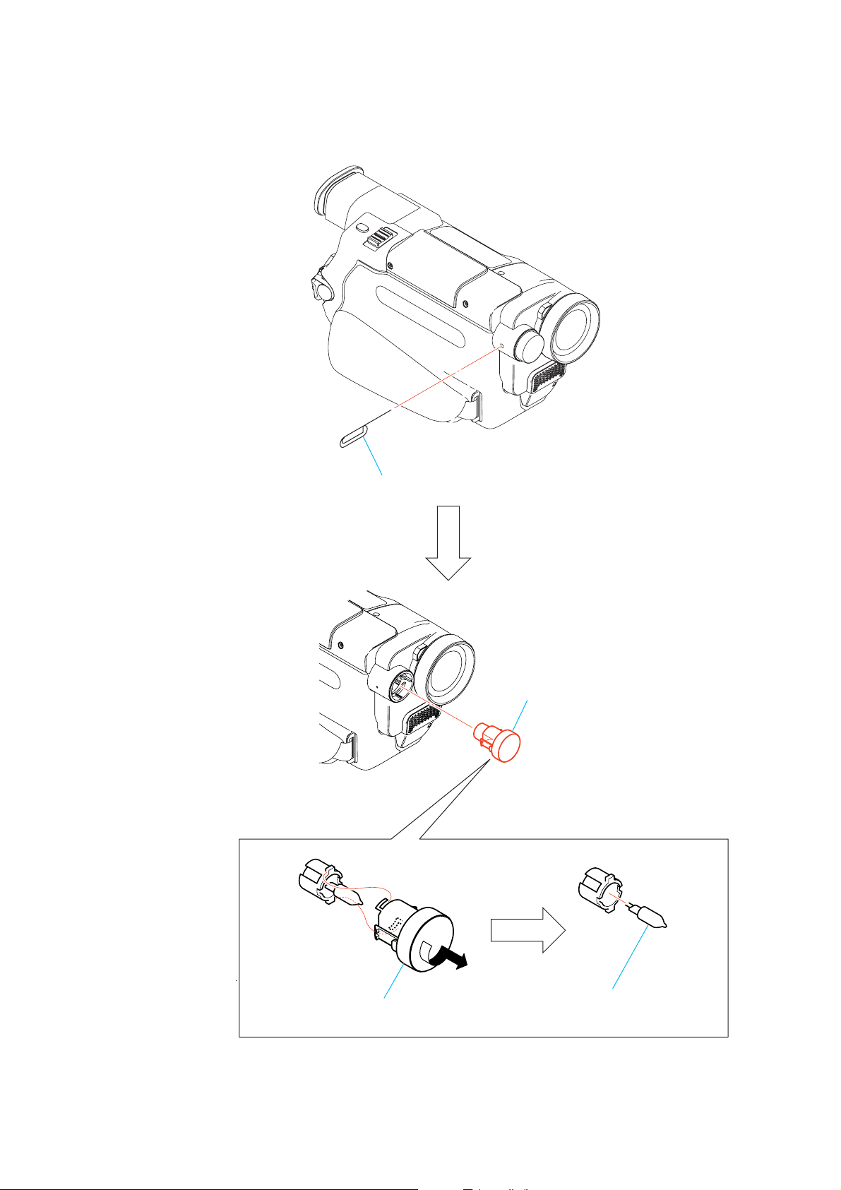
2-1. VIDEO LIGHT
DCR-TRV250
1 Push in the dent inside hole with wire tip.
2 Video light
3 Remove in the direction of the arrow A.
2-3
A
4 Halogen lamp
DCR-TRV250
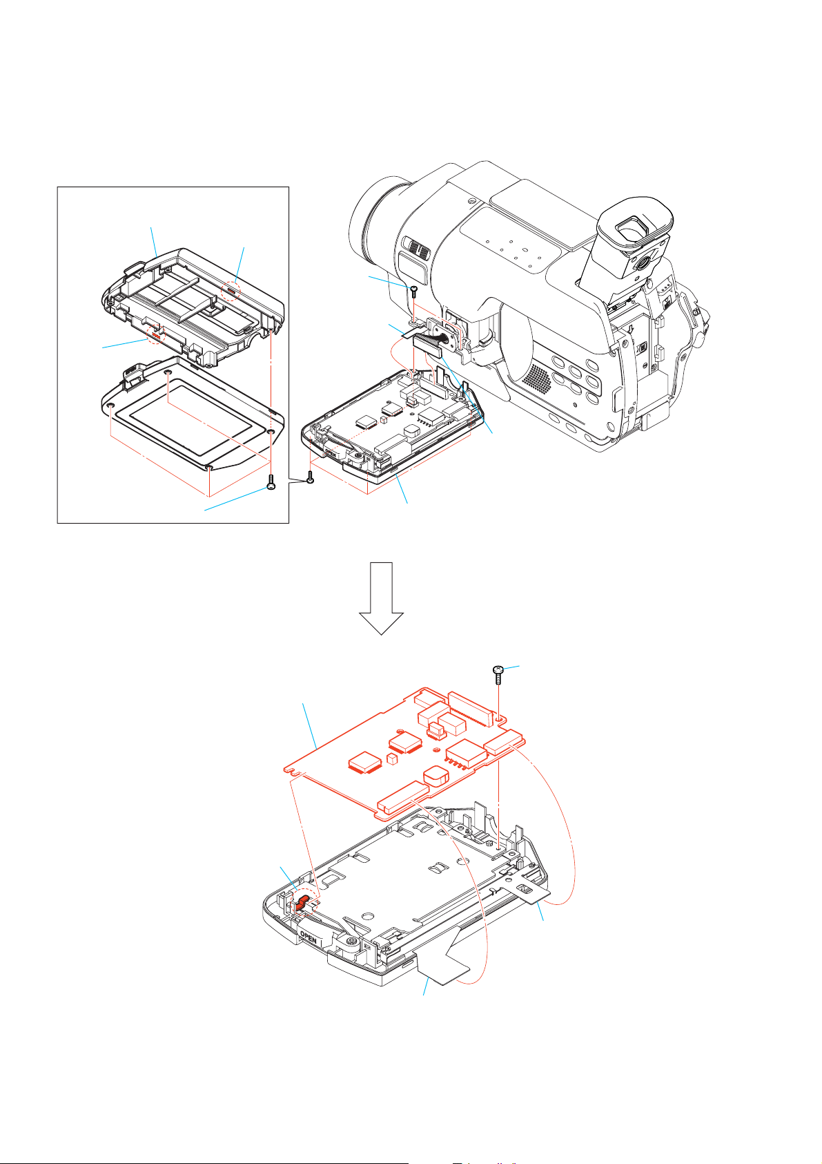
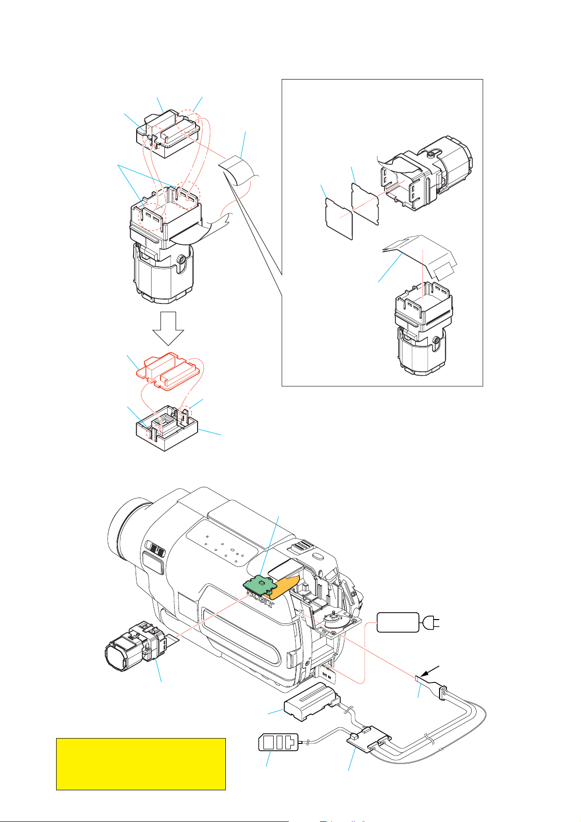
2-2. PD-180 BOARD
Bottom View
4 P cabinet (C)
3 Claw
2 Claw
5 Two screws
(M1.7)
7 Flexible board
(CN5702)
1 Four screws (M1.7)
6 Connector
(CN5701)
8 P cabinet (M) assembly
qa Screw (M1.7)
qd PD-180 board
qs Claw
9 Flexible board
(CN5601)
0 Flexible board
(CN5501)
2-4
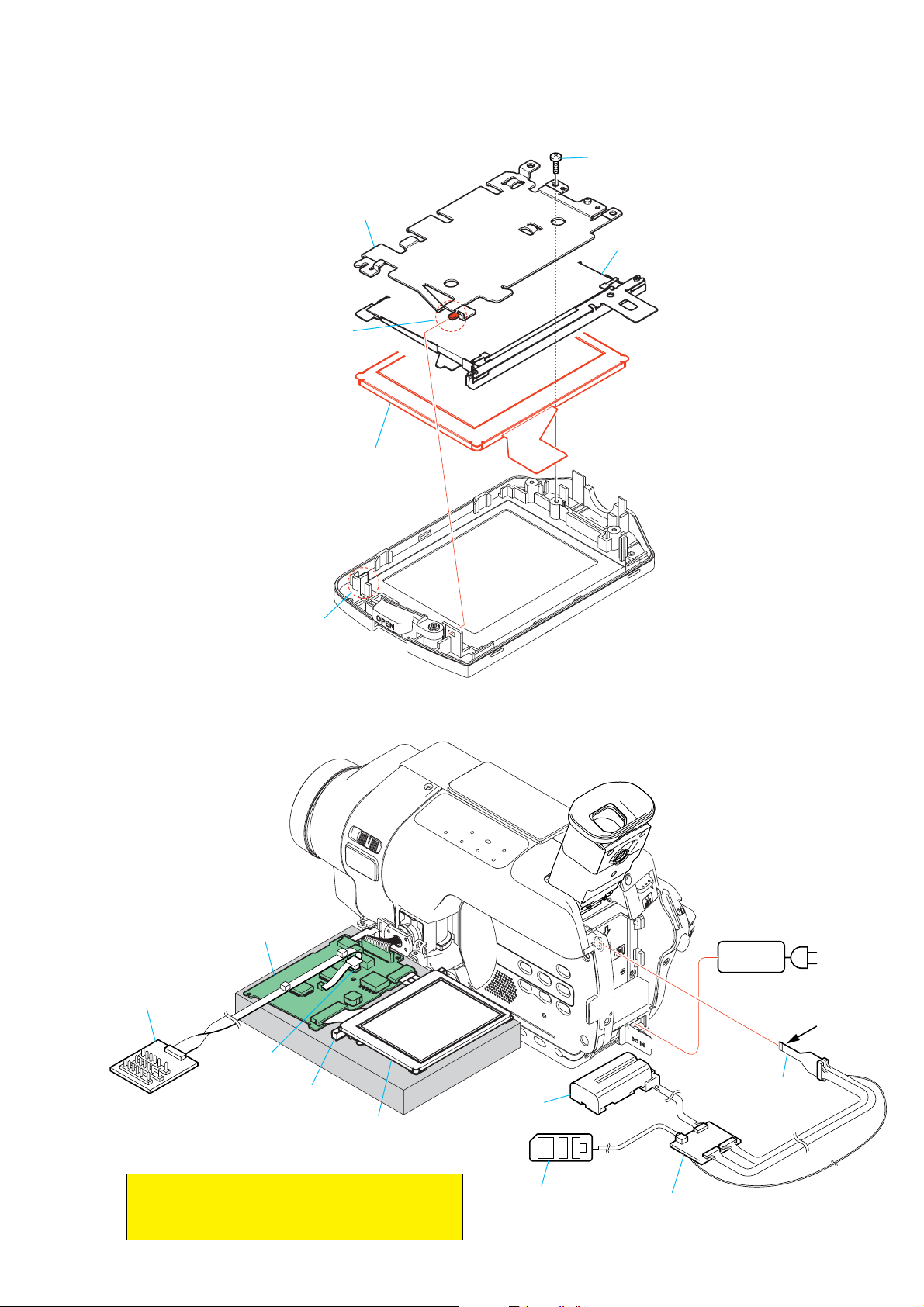
2-3. LCD MODULE
DCR-TRV250
1 Screw (M1.7)
4 P flame
5 Backlight unit
3 Claw
6 LCD module
2 Boss
[SERVICE POSITION TO CHECK PD-180 BOARD]
PD-180 board
Multi CPC jig
(J-6082-311-A)
CN5502
Back light unit
LCD panel
Info lithium battery
(L series)
AC power
adaptor
Contacting surface
CPC jig connector
(J-6082-539-A) (Note)
AC IN
Note : The "Jig Modification" is necessary for connecting
the adjusting remote commander to this set.
Modify the jig by referring to page 1-3.
Adjustment remote
commander (RM-95)
2-5
I/F unit for LANC control
(J-6082-521-A) (Note)
DCR-TRV250
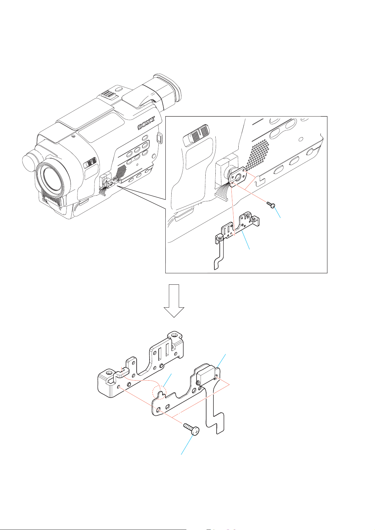
2-4. CONTROL SWITCH BLOCK (PR-3000)
4 Claw
1 Two screws
(M1.7)
2 Hinge bracket
5 Control switch block
(PR-3000)
3 Two screws
(M1.7)
2-6
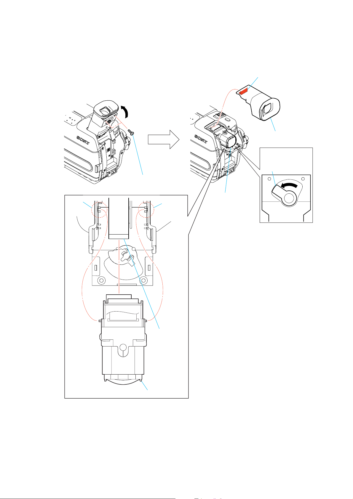
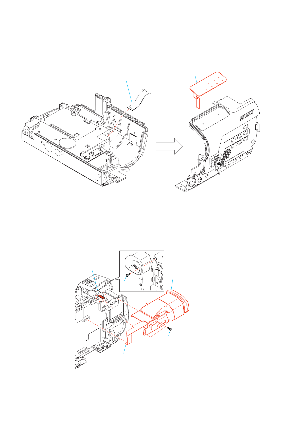
2-5. VF LENS (B) ASSEMBLY
1 Raise the EVF in the A direction.
A
2 Two tapping screws
(M1.7)
DCR-TRV250
3 Claw
4 EVF cabinet (upper)
When installing
VF lens (B) assembly,
slide the lever
in the arrow direction.
Slit
Slit
VF lens (B) assembly
6 Flexible board
5 VF lens (B) assembly
2-7
DCR-TRV250
2-6. LB-083 BOARD
4 Liquid crystal indicator module
2 Two claws
Handle with care,
these are fragile.
3 Two claws
1 Flexible board
(CN702)
When removing the liquid crystal indicator module,
do not face down the side which the board is mounted.
Otherwise, the illuminator and the prism sheet
may fall down.
prism sheet
illuminator
After removing the liquid
crystal indicator module,
over wrap with adhesive tape
and paper in order not to let
the illuminator and
the prism sheet fall down.
7 LB-083 board
5 Claw
6 Claw
Lamp guide
[SERVICE POSITION TO CHECK LB-083 BOARD]
LB-083 board
AC power
adaptor
AC IN
VF lens (B) assembly
Info lithium battery
(L series)
Note : The "Jig Modification" is necessary
for connecting the adjusting
remote commander to this set.
Modify the jig by referring to page 1-3.
Adjustment remote
commander (RM-95)
2-8
Contacting surface
CPC jig connector
(J-6082-539-A) (Note)
I/F unit for LANC control
(J-6082-521-A) (Note)
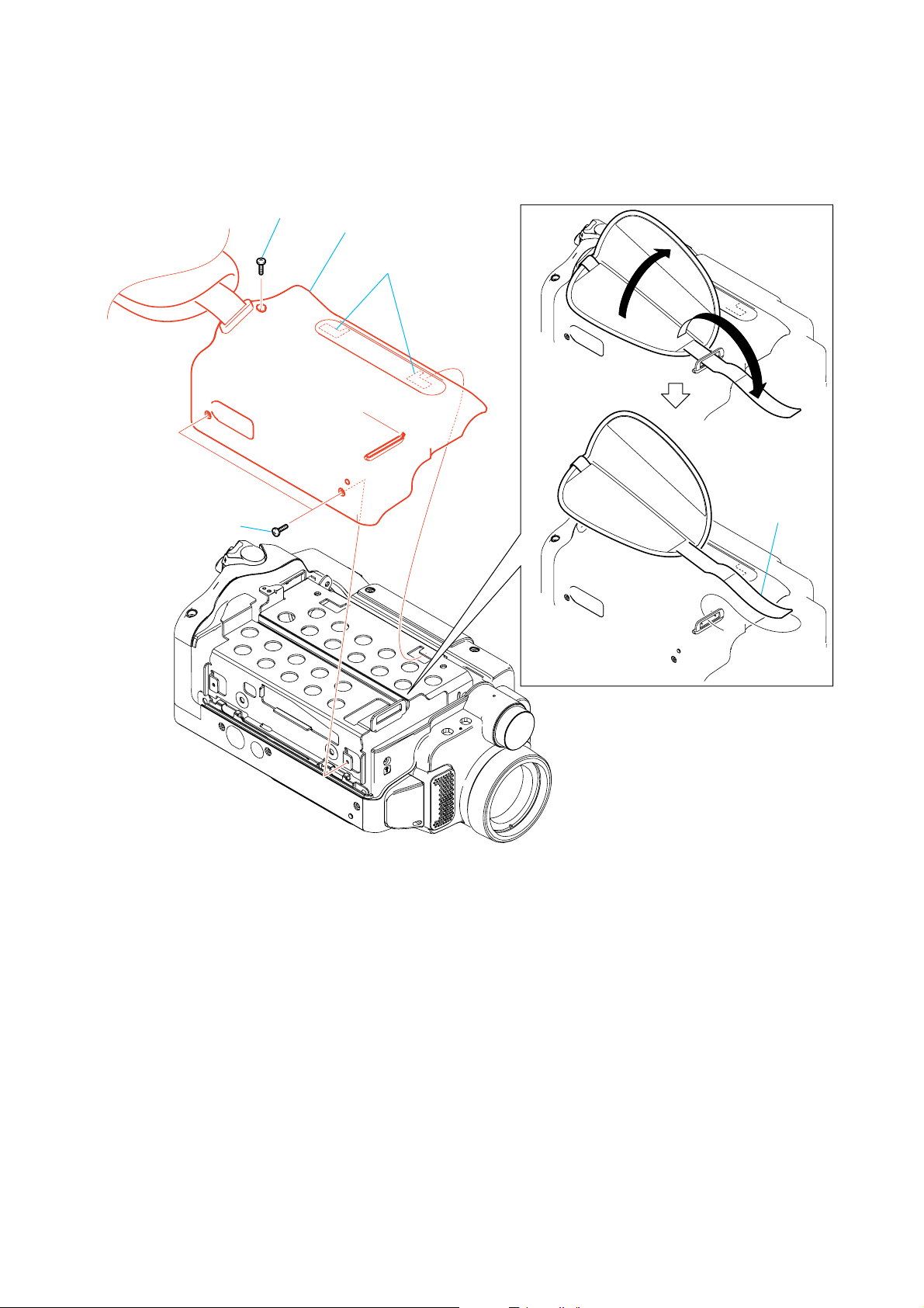
2-7. CABINET (L) ASSEMBLY
5 Screw
(M2)
7 Cabinet (L) assembly
DCR-TRV250
4 Two screws
(M2)
6 Two claws
1
2
3 Grip belt
2-9
DCR-TRV250
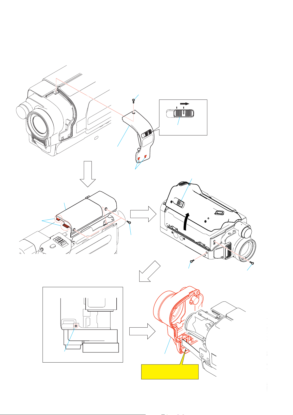
2-8. F PANEL BLOCK ASSEMBLY
2 Screw
ONOFF
1 Slide the NS knob to
the position of "ON".
4 Ornamental ring
assembly
6 Two claws
7 Cabinet upper
Top View
3 Two claws
5 Two screws
(M2)
8 Slide lever.
9
0 Screw
(M2)
qa Screw
(M2)
qs Screw
(M2)
qd F panel block
assembly
Note: Remove it while taking
care as the flexible board
is connected.
2-10
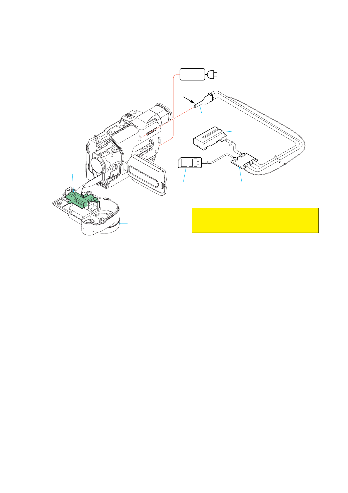
[SERVICE POSITION TO CHECK SI-035 BOARD]
DCR-TRV250
SI-035 board
Adjustment remote
commander (RM-95)
F panel block assembly
AC power
adaptor
Contacting
surface
AC IN
CPC jig connector
(J-6082-539-A) (Note)
Info lithium battery
(L series)
I/F unit for LANC control
(J-6082-521-A) (Note)
Note : The "Jig Modification" is necessary for connecting
the adjusting remote commander to this set.
Modify the jig by referring to page 1-3.
2-11
DCR-TRV250
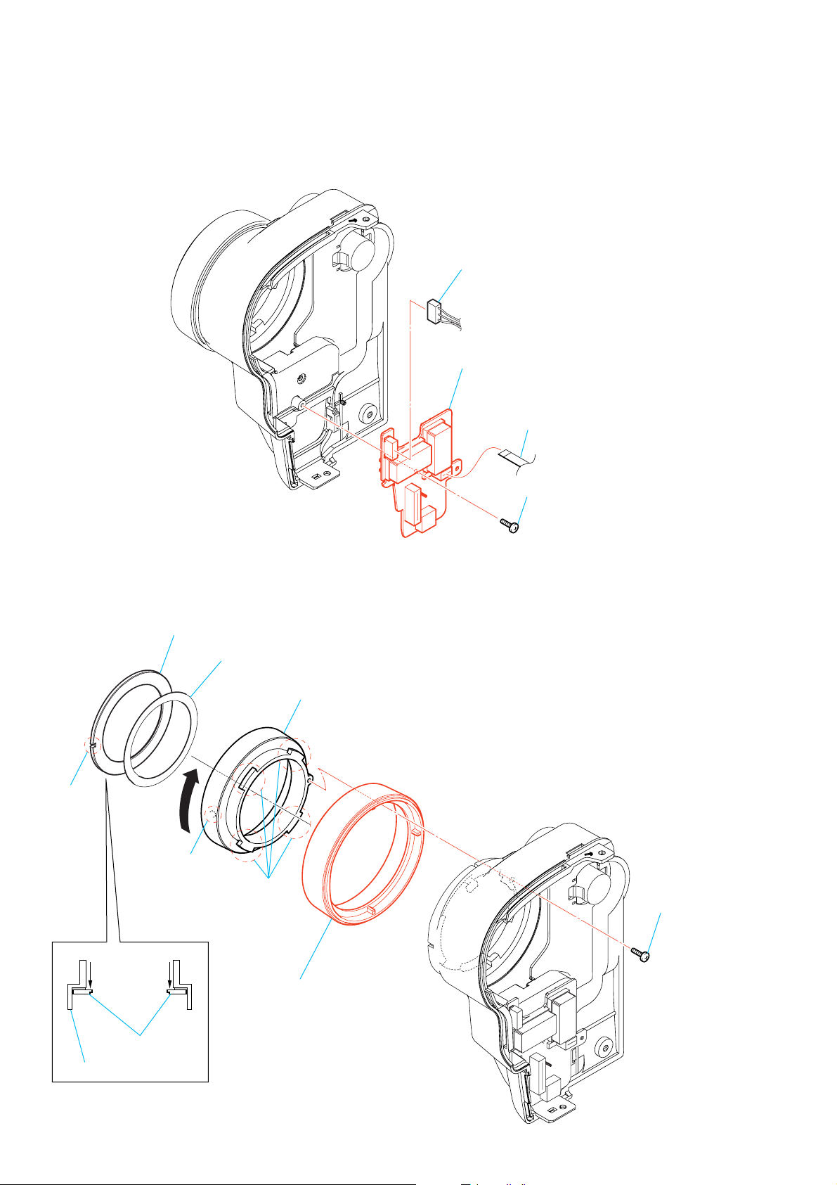
2-9. SI-035 BOARD
1 Connector
(CN751)
4 SI-035 board
2 Flexible board
(CN754)
2-10.FRONT RING
Name plate
Slit
2
Boss
3 Screw
(M1.7)
7 Plate adhesive sheet
4 Filter screw (30)
3 Four claws
1 Screw (M1.7)
SECTIONAL VIEW
6 Push name plate.
Filter screw (30)
5 Front ring (30)
2-12
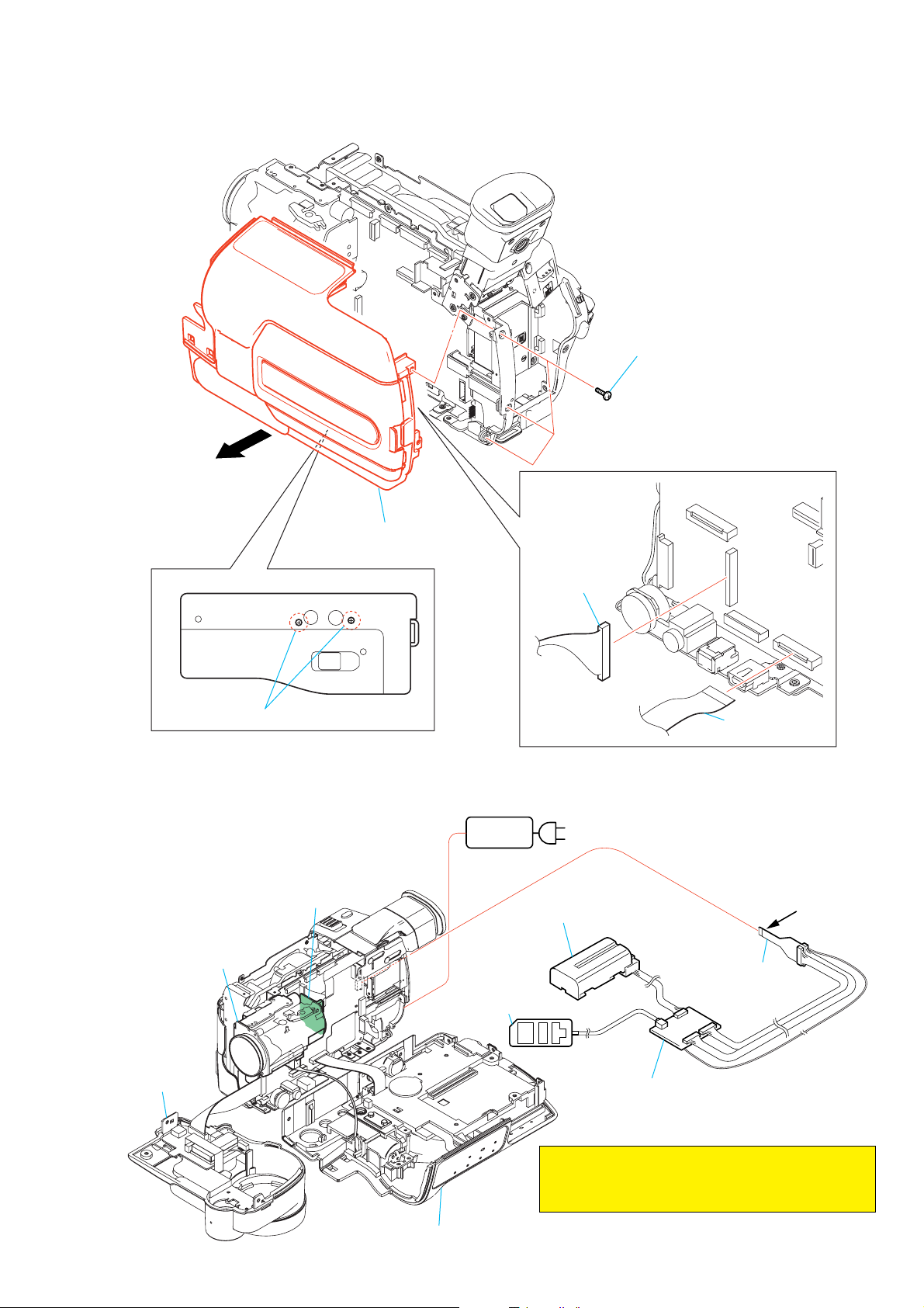
2-11.CABINET (R) BLOCK ASSEMBLY
3
DCR-TRV250
2 Three screws
(M2)
6 Cabinet (R) block
assembly
Bottom View
1 Two screws (M2)
4 Connector
(CN1003)
[SERVICE POSITION TO CHECK THE CAMERA SECTION]
AC power
adaptor
CD-418 board
Lens block assembly
Adjustment remote
commander (RM-95)
AC IN
Info lithium battery
(L series)
5 Flexible board
(CN1007)
Contacting surface
CPC jig connector
(J-6082-539-A) (Note)
F panel block
assembly
I/F unit for LANC control
(J-6082-521-A) (Note)
Note : The "Jig Modification" is necessary for connecting
the adjusting remote commander to this set.
Modify the jig by referring to page 1-3.
Cabinet (R) block assembly
2-13
DCR-TRV250
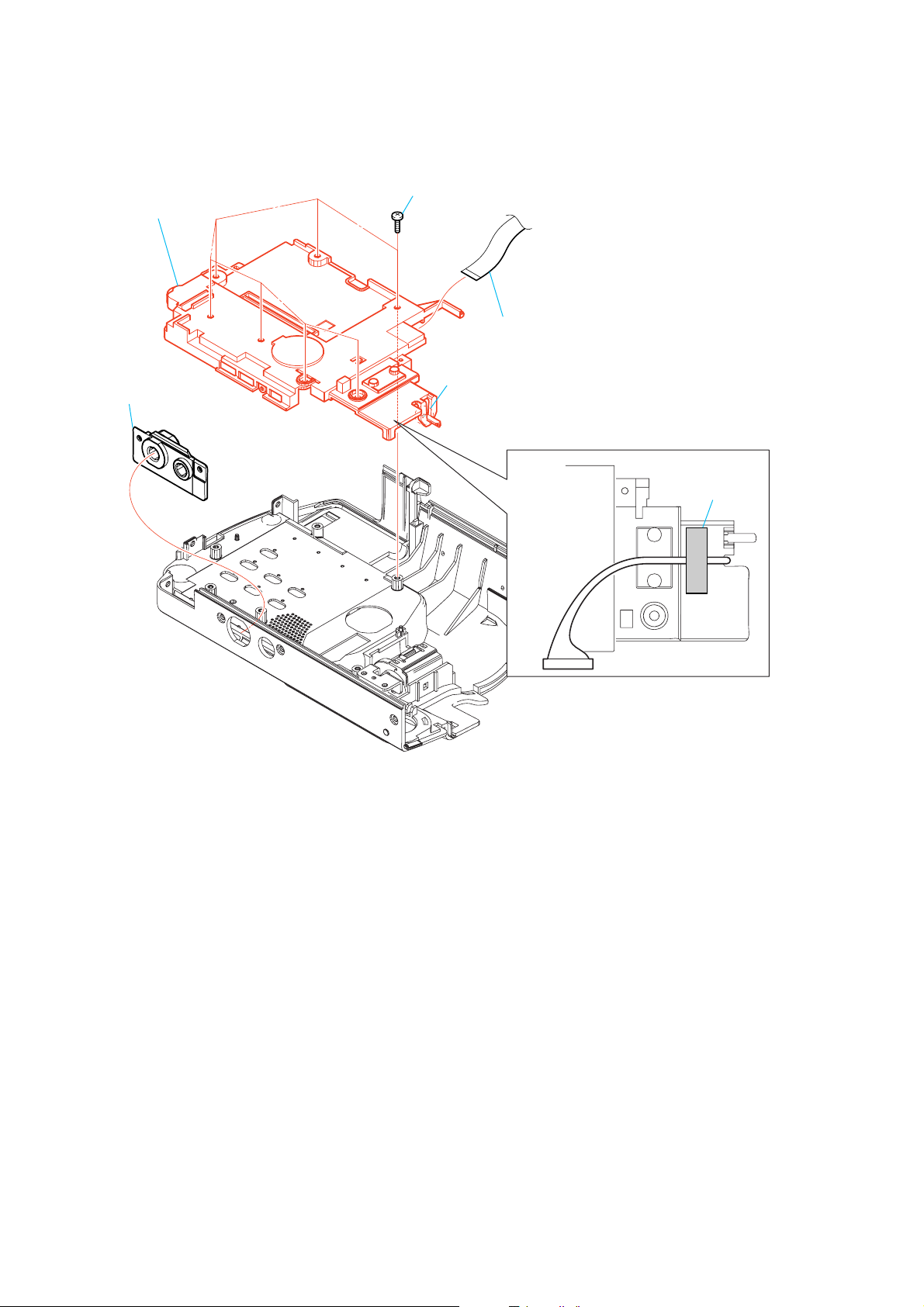
2-12.CONTROL SWITCH BLOCK (CF-3000)
6 Control switch block
(CF-3000)
1 Tripod screw
4 Seven screws
2 Flexible board
5 Claw
3 Tape (A)
2-14
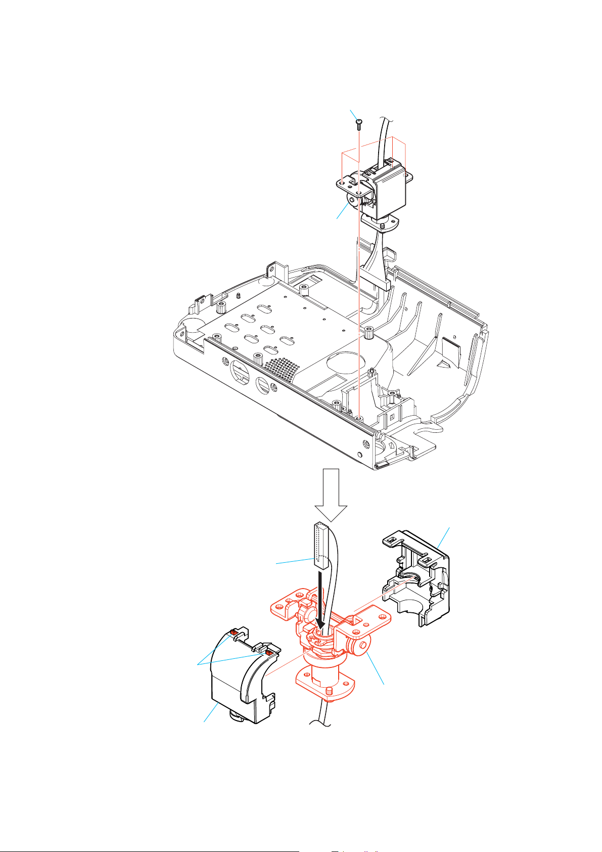
2-13.HINGE ASSEMBLY
DCR-TRV250
1 Four screws
2 Hinge block
7 Harness (PD-118)
3 Two claws
5 Hinge cover (M)
4 Hinge cover (C)
6 Hinge assembly
2-15
DCR-TRV250
2-14.CONTROL SWITCH BLOCK (FK-3000)
1 Flexible board
2 Control swith block
(FK-3000)
2-15.EVF BLOCK ASSEMBLY
4 Remove the flexibl board
from the claw.
5 EVF block assembly
2 Screw
(M2)
3 Two screws
(M1.7)
1 Flexible board
(CN1005)
2-16
[SERVICE POSITION TO CHECK VC-305 BOARD (SIDE A)]
Cabinet (R) block assembly
DCR-TRV250
Info lithium battery
(L series)
Adjustment remote
commander (RM-95)
Note : The "Jig Modification" is necessary for connecting
the adjusting remote commander to this set.
Modify the jig by referring to page 1-3.
I/F unit for LANC control
(J-6082-521-A) (Note)
AC IN
AC power
adaptor
CPC jig connector
(J-6082-539-A) (Note)
Contacting
surface
VC-305 board
2-17
DCR-TRV250
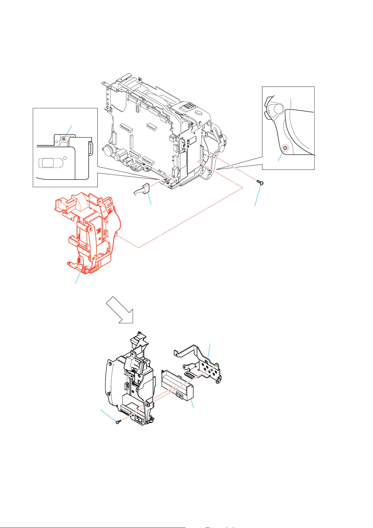
2-16.BATTERY PANEL BLOCK ASSEMBLY
Bottom View
1 Screw
(M2)
Side View
2 Screw (M2)
5 Battery panel block
assembly
4 Connector (CN4001)
3 Screw (M2)
7 Strap sheet metal
(lower)
6 Screw
(M2)
8 Battery terminal board
2-18
 Loading...