

Sony CDXGT-10-M Service manual
CDX-GT10M
SERVICE MANUAL
Ver. 1.2 2006. 09
• The tuner and CD sections have no adjustments.
AUDIO POWER SPECIFICATIONS
POWER OUTPUT AND TOTAL HARMONIC DISTORTION
23.2 watts per channel minimum continuous average power into
4 ohms, 4 channels driven from 20 Hz to 20 kHz with no more
than 5% total harmonic distortion.
SPECIFICATIONS
US Model
Canadian Model
Model Name Using Similar Mechanism
CD Drive Mechanism Type MG-611XE-186//Q
Optical Pick-up Name KSS1000E
CDX-GT10W/GT100/
GT150/GT150S
CD Player section
Signal-to-noise ratio: 120 dB
Frequency response: 10 – 20,000 Hz
Wow and flutter: Below measurable limit
Tuner section
FM
Tuning range: 87.5 – 108.0 MHz (at 50 kHz step)
87.5 – 107.9 MHz (at 200 kHz step)
FM tuning interval: 50 kHz/200 kHz switchable
Antenna terminal: External antenna connector
Intermediate frequency: 10.7 MHz/450 kHz
Usable sensitivity: 9 dBf
Selectivity: 75 dB at 400 kHz
Signal-to-noise ratio: 67 dB (stereo), 69 dB (mono)
Harmonic distortion at 1 kHz:
0.5 % (stereo), 0.3 % (mono)
Separation: 35 dB at 1 kHz
Frequency response: 30 – 15,000 Hz
AM
Tuning range: 531 – 1,602 kHz (at 9 kHz step)
530 – 1,710 kHz (at 10 kHz step)
AM tuning interval: 9 kHz/10 kHz switchable
Antenna terminal: External antenna connector
Intermediate frequency: 10.7 MHz/450 kHz
Sensitivity: 30 µV
Power amplifier section
Outputs: Speaker outputs (sure seal connectors)
Speaker impedance: 4 – 8 ohms
Maximum power output: 52 W × 4 (at 4 ohms)
General
Outputs: Audio outputs terminal (sub/rear switchable)
Power antenna relay control terminal
Power amplifier control terminal
Inputs: Antenna input terminal
AUX input jack (stereo mini jack)
Tone controls: Low: ±10 dB at 60 Hz (XPLOD)
Mid: ±10 dB at 1 kHz (XPLOD)
High: ±10 dB at 10 kHz (XPLOD)
Power requirements: 12 V DC car battery (negative ground)
Dimensions: Approx. 178 × 50 × 179 mm
(7 1/8 × 2 × 7 1/8 in) (w/h/d)
Mounting dimensions: Approx. 182 × 53 × 161 mm
(7 1/4 × 2 1/8 × 6 3/8 in) (w/h/d)
Mass: Approx. 1.2 kg (2 lb 11 oz)
Supplied accessories: Parts for installation and connections (1 set)
Design and specifications are subject to change
without notice.
9-887-163-03
2006I04-1
© 2006. 09
FM/AM COMPACT DISC PLAYER
Sony Corporation
eVehicle Division
Published by Sony Techno Create Corporation
1
CDX-GT10M
SERVICE NOTES
CAUTION
Use of controls or adjustments or performance of procedures other
than those specified herein may result in hazardous radiation
exposure.
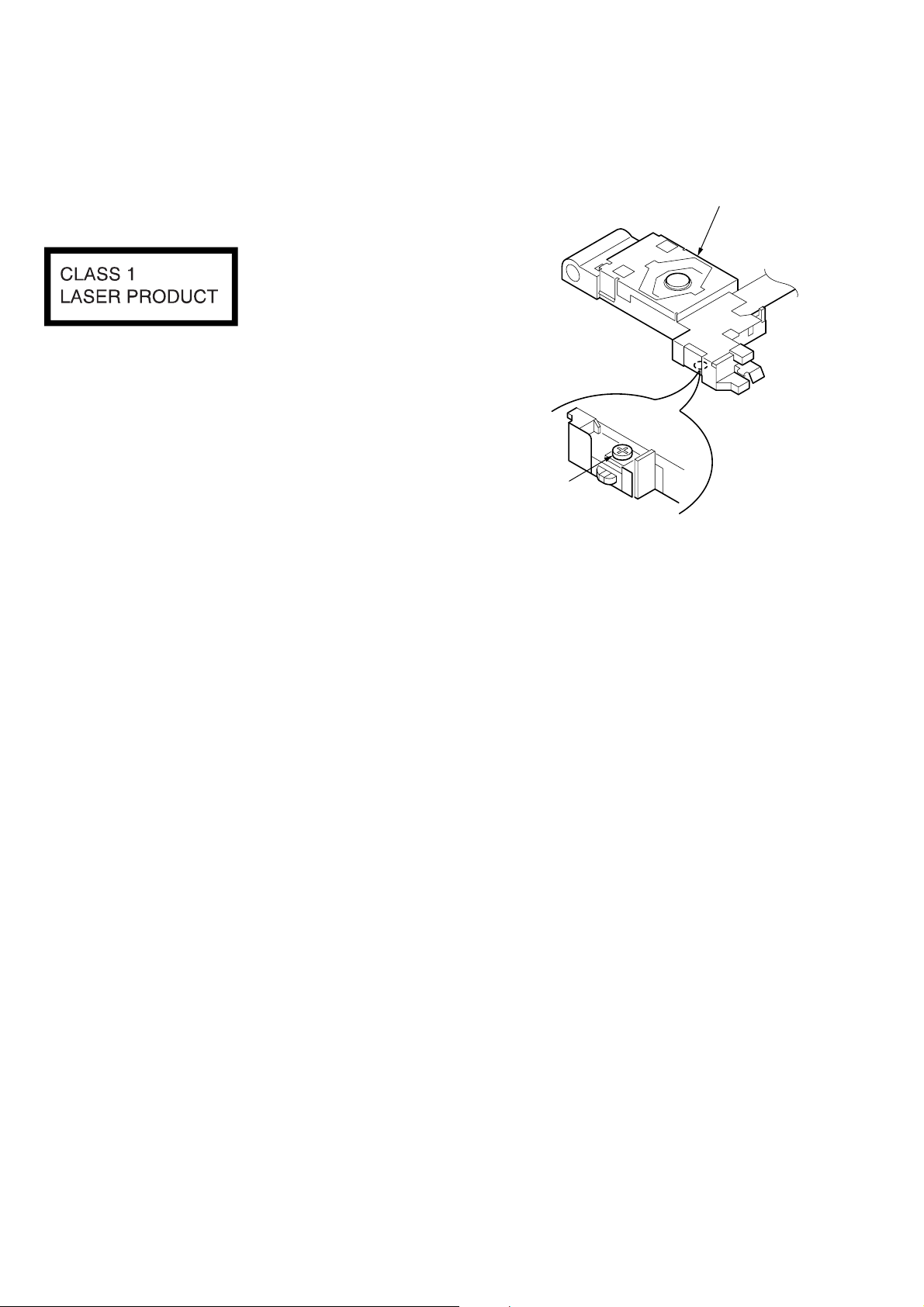
This label is located on the bottom of the chassis.
NOTES ON HANDLING THE OPTICAL PICK-UP BLOCK
OR BASE UNIT
The laser diode in the optical pick-up block may suffer electrostatic
breakdown because of the potential difference generated by the
charged electrostatic load, etc. on clothing and the human body.
During repair, pay attention to electrostatic breakdown and also use
the procedure in the printed matter which is included in the repair
parts.
The flexible board is easily damaged and should be handled with
care.
NOTES ON LASER DIODE EMISSION CHECK
The laser beam on this model is concentrated so as to be focused on
the disc reflective surface by the objective lens in the optical pickup block. Therefore, when checking the laser diode emission, observe from more than 30 cm away from the objective lens.
If the optical pick-up block is defective, please replace the whole
optical pick-up block.
Never turn the semi-fixed resistor located at the side of optical
pick-up block.
optical pick-up
semi-fixed resistor
TEST DISCS
This set can playback CD-R and CD-ROM discs. The following
test discs should be used to check the capability:
CD-R test disc TCD-R082LMT (Part No. J-2502-063-1)
CD-RW test disc TCD-W082L (Part No. J-2502-063-2)
Notes on Chip Component Replacement
•Never reuse a disconnected chip component.
• Notice that the minus side of a tantalum capacitor may be damaged by heat.
SAFETY-RELATED COMPONENT WARNING!!
COMPONENTS IDENTIFIED BY MARK 0 OR DOTTED LINE
WITH MARK 0 ON THE SCHEMATIC DIAGRAMS AND IN
THE PARTS LIST ARE CRITICAL TO SAFE OPERATION.
REPLACE THESE COMPONENTS WITH SONY P ARTS WHOSE
PART NUMBERS APPEAR AS SHOWN IN THIS MANUAL OR
IN SUPPLEMENTS PUBLISHED BY SONY.
ATTENTION AU COMPOSANT AYANT RAPPORT
À LA SÉCURITÉ!!
LES COMPOSANTS IDENTIFIÉS P AR UNE MARQUE 0 SUR LES
DIAGRAMMES SCHÉMATIQUES ET LA LISTE DES PIÈCES
SONT CRITIQUES POUR LA SÉCURITÉ DE FONCTIONNEMENT.
NE REMPLACER CES COMPOSANTS QUE PAR DES PIÈCES
SONY DONT LES NUMÉROS SONT DONNÉS DANS CE MANUEL
OU DANS LES SUPPLÉMENTS PUBLIÉS PAR SONY.
2
CDX-GT10M
D
Notes on CD-DA/CD-R/CD-RW
• CD playback:
You can play CD-DA and CD-R/CD-RW for audio use.
z
UNLEADED SOLDER
Boards requiring use of unleaded solder are printed with the lead
free mark (LF) indicating the solder contains no lead.
(Caution: Some printed circuit boards may not come printed with
the lead free mark due to their particular size.)
: LEAD FREE MARK
Unleaded solder has the following characteristics.
• Unleaded solder melts at a temperature about 40°C higher than
ordinary solder.
Ordinary soldering irons can be used but the iron tip has to be
applied to the solder joint for a slightly longer time.
Soldering irons using a temperature regulator should be set to
about 350°C.
Caution: The printed pattern (copper foil) may peel away if the
heated tip is applied for too long, so be careful!
• Strong viscosity
Unleaded solder is more viscous (sticky, less prone to flow)
than ordinary solder so use caution not to let solder bridges
occur such as on IC pins, etc.
• Usable with ordinary solder
It is best to use only unleaded solder but unleaded solder may
also be added to ordinary solder.
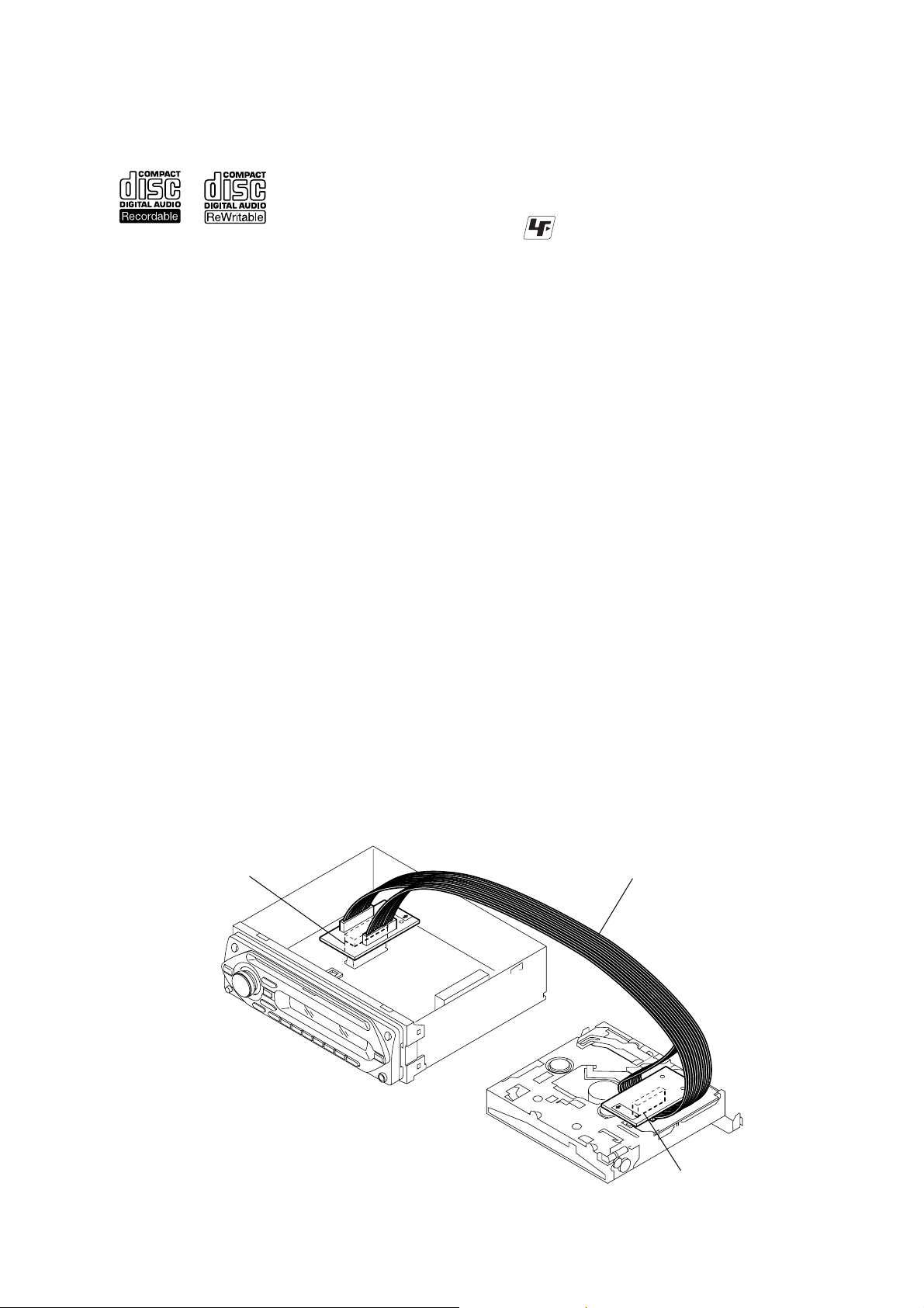
EXTENSION CABLE AND SERVICE POSITION
When repairing or servicing this set, connect the jig (extension cable)
as shown below.
• Connect the MAIN board (CNP301) and the SER VO board (CN1)
with the extension cable (Part No. J-2502-076-1).
MAIN BOARD
CNP301
J-2502-076-1
SERVO BOAR
CN1
3

CDX-GT10M
TABLE OF CONTENTS
1. GENERAL
Location of controls and basic operations ...............................5
Connections .............................................................................6
2. DISASSEMBL Y
2-1. Sub Panel Assy.................................................................... 8
2-2. CD Mechanism Block ......................................................... 8
2-3. Main Board .........................................................................9
2-4. Chassis (T) Sub Assy .......................................................... 9
2-5. Roller Arm Assy ................................................................ 10
2-6. Chassis (OP) Assy............................................................. 10
2-7. Optical Pick-up .................................................................11
2-8. SL Motor Assy (M902) ..................................................... 11
2-9. LE Motor Assy (M903)..................................................... 12
2-10. Servo Board....................................................................... 12
3. DIAGRAMS
3-1. Block Diagram – CD Section –......................................... 13
3-2. Block Diagram – Main Section –...................................... 14
3-3. Block Diagram – Display Section –.................................. 15
3-4. Circuit Boards Location .................................................... 15
3-5. Printed Wiring Boards – CD Mechanism Section – ......... 16
3-6. Schematic Diagram – CD Mechanism Section – .............. 17
3-7. Printed Wiring Board – Main Section –............................ 18
3-8. Schematic Diagram – Main Section (1/3) – ...................... 19
3-9. Schematic Diagram – Main Section (2/3) – ...................... 20
3-10. Schematic Diagram – Main Section (3/3) –...................... 21
3-11. Printed Wiring Boards – Key Section – ............................22
3-12. Schematic Diagram – Key Section – ................................ 23
4. EXPLODED VIEWS
4-1. Main Section ..................................................................... 31
4-2. Front Panel Section ........................................................... 32
4-3. CD Mechanism Section (1) (MG-611XE-186//Q)............ 33
4-4. CD Mechanism Section (2) (MG-611XE-186//Q)............ 34
4-5. CD Mechanism Section (3) (MG-611XE-186//Q)............ 35
4-6. CD Mechanism Section (4) (MG-611XE-186//Q)............ 36
5. ELECTRICAL PARTS LIST ........................................ 37
4
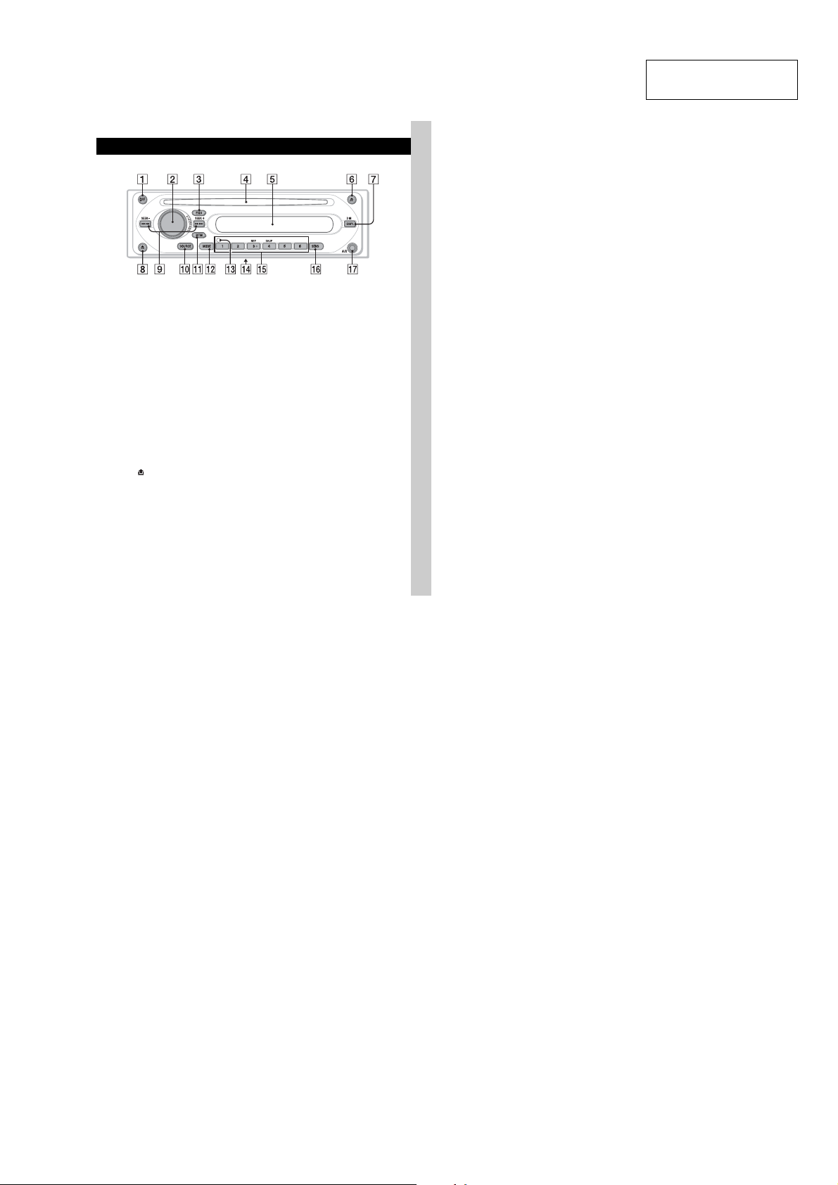
Location of controls and basic operations
Main unit
CDX-GT10M
SECTION 1
GENERAL
CDX-GT10M
This section is extracted
from instruction manual.
Refer to the pages listed for details.
A OFF button
To po wer off; stop the source.
B Volume control dial/select button 6
To ad ju st volu me (rotate); select setup items
(press and rotate).
C EQ3 (equalizer) button 6
To se le ct an equalizer ty pe (XPLOD,
VOCAL, CLUB, JAZZ, NEW AGE, ROCK,
CUSTOM or OFF).
D Disc slot
To in se rt the disc (label side up), playback
starts.
E Display window
F Z (eject) button
To ej ect the disc.
G DSPL (display)/DIM (dimmer) button
4
To ch ange display items (press); change the
display brightness (press and hol d).
H (front panel release) button 4
I SEEK –/+ buttons
CD:
To sk ip tracks (press); skip tracks
continuously (press, then press again within
about 1 second and hold); reverse/fastforward a track (press and hold).
Radio:
To tune in stations automatically (press); find
a station manually (press and hold).
J SOURCE button
To power on; change the source (Radio/CD/
AUX).
K BTM button 6
To s t ar t t he BTM functi on ( press and hold).
L MODE button 6
To sele ct the radio band (FM/AM).
M RESET button (located behind the front
panel) 4
N Frequency select switch (located on
the bottom of the unit)
See “Frequency select sw i tch” in the
supplied installation/connections manual.
O Number buttons
CD:
(3): REP
To pl ay the current track repeatedly.
(4): SHUF
To pl ay th e tracks in random order.
Radio:
To r e ce iv e stored stations (press); store
stations (press and hold).
P SENS button
To improve weak reception: LOCAL/
MONO.
Q AUX input jack 7
To conn ec t a portable audio device.
5
5
CDX-GT10M
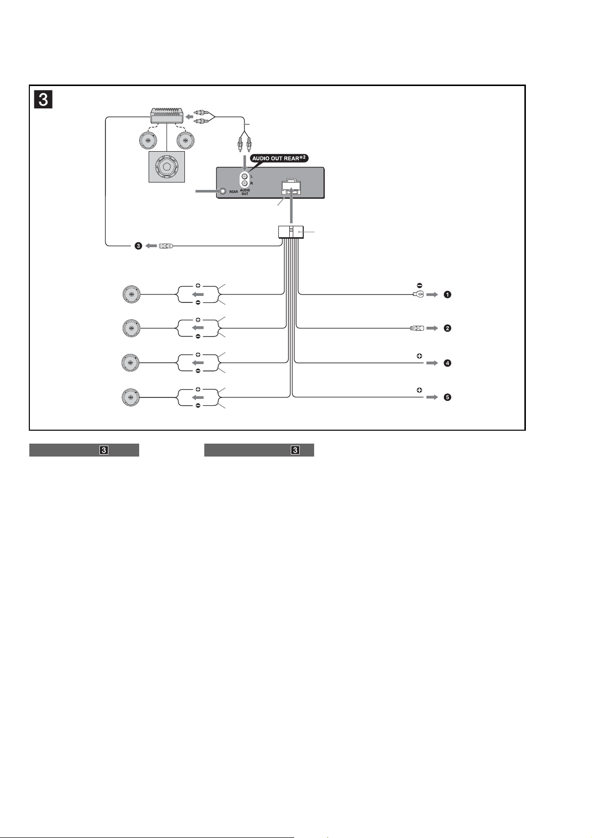
• CONNECTIONS
from car antenna
à partir de l’antenne de la voiture
BUS
AUDIO
IN
1
*
L
R
Fuse (10 A)
Fusible (10 A)
1
*
RCA pin cord (not supplied)
2
*
AUDIO OUT can be switched to SUB
or REAR.
For details, see the supplied
Operating Instructions.
1
*
Cordon à broche RCA (non fourni)
2
*
AUDIO OUT peut être commuté sur
SUB ou REAR.
Pour obtenir plus de détails, reportez-
vous au mode d’emploi fourni.
Left
Gauche
Right
Droit
Left
Gauche
Right
Droit
Connection diagram
1 To a metal surface of the car
First connect the black ground lead, then connect the yellow
and red power input leads.
2 To the power antenna control lead or power
supply lead of antenna booster amplifi er
Notes
•
It is not necessary to connect this lead if there is no power
antenna or antenna booster, or with a manually-operated
telescopic antenna.
•
When your car has a built-in FM/AM antenna in the rear/
side glass, see “Notes on the control and power supply
leads.”
3 To AMP REMOTE IN of an optional power
amplifi er
This connection is only for amplifi ers. Connecting any other
system may damage the unit.
4 To the +12 V power terminal which is
energized in the accessory position of the
ignition key switch
Notes
•
If there is no accessory position, connect to the +12 V
power (battery) terminal which is energized at all times.
Be sure to connect the black ground lead to a metal
surface of the car fi rst.
•
When your car has a built-in FM/AM antenna in the rear/
side glass, see “Notes on the control and power supply
leads.”
5 To the +12 V power terminal which is
energized at all times
Be sure to connect the black ground lead to a metal surface
of the car fi rst.
Notes on the control and power supply leads
•
The power antenna control lead (blue) supplies +12 V DC
when you turn on the tuner.
•
When your car has built-in FM/AM antenna in the rear/side
glass, connect the power antenna control lead (blue) or the
accessory power input lead (red) to the power terminal of the
existing antenna booster. For details, consult your dealer.
•
A power antenna without a relay box cannot be used with this
unit.
Memory hold connection
When the yellow power input lead is connected, power will
always be supplied to the memory circuit even when the ignition
switch is turned off.
Notes on speaker connection
•
Before connecting the speakers, turn the unit off.
•
Use speakers with an impedance of 4 to 8 ohms, and with
adequate power handling capacities to avoid its damage.
•
Do not connect the speaker terminals to the car chassis, or
connect the terminals of the right speakers with those of the
left speaker.
•
Do not connect the ground lead of this unit to the negative (–)
terminal of the speaker.
•
Do not attempt to connect the speakers in parallel.
•
Connect only passive speakers. Connecting active speakers
(with built-in amplifi ers) to the speaker terminals may damage
the unit.
•
To avoid a malfunction, do not use the built-in speaker leads
installed in your car if the unit shares a common negative (–)
lead for the right and left speakers.
•
Do not connect the unit’s speaker leads to each other.
Note on connection
If speaker and amplifi er are not connected correctly, “FAILURE”
appears in the display. In this case, make sure the speaker and
amplifi er are connected correctly.
AMP REM
Max. supply current 0.3 A
Courant max. fourni 0,3 A
1 À un point métallique de la voiture
2 Vers le câble de commande d’antenne
3 Au niveau de AMP REMOTE IN de
4 À la borne +12 V qui est alimentée quand la
5 À la borne +12 V qui est alimentée en
Remarques sur les câbles de commande et d’alimentation
•
•
•
Raccordement pour la conservation de la mémoire
Lorsque le câble d’entrée d’alimentation jaune est raccordé, le
circuit de la mémoire est alimenté en permanence même si la clé
de contact est sur la position d’arrêt.
Remarques sur le raccordement des haut-parleurs
•
•
•
•
•
•
•
•
Remarque sur le raccordement
Si les haut-parleurs et l’amplifi cateur ne sont pas raccordés
correctement, le message « FAILURE » s’affi che. Dans ce cas,
assurez-vous que les haut-parleurs et l’amplifi cateur sont bien
raccordés.
Blue/white striped
Rayé bleu/blanc
White
Blanc
White/black striped
Rayé blanc/noir
Gray
Gris
Gray/black striped
Rayé gris/noir
Green
Vert
Green/black striped
Rayé vert/noir
Purple
Mauve
Purple/black striped
Rayé mauve/noir
Schéma de raccordement
Branchez d’abord le câble de mise à la masse noir et,
ensuite, les câbles d’entrée d’alimentation jaune et rouge.
électrique ou le câble d’alimentation de
l’amplifi cateur d’antenne
Remarques
•
Il n’est pas nécessaire de raccorder ce câble s’il n’y a pas
d’antenne électrique ni d’amplifi cateur d’antenne, ou avec
une antenne télescopique manuelle.
•
Si votre voiture est équipée d’une antenne FM/AM
intégrée dans la vitre arrière/latérale, voir « Remarques
sur les câbles de commande et d’alimentation ».
l’amplifi cateur de puissance en option
Ce raccordement s’applique uniquement aux amplifi cateurs.
Le branchement de tout autre système risque
d’endommager l’appareil.
clé de contact est sur la position accessoires
Remarques
•
S’il n’y a pas de position accessoires, raccordez la borne
d’alimentation (batterie) +12 V qui est alimentée en
permanence.
Raccordez d’abord le câble de mise à la masse noir à un
point métallique du véhicule.
•
Si votre voiture est équipée d’une antenne FM/AM
intégrée dans la vitre arrière/latérale, voir « Remarques
sur les câbles de commande et d’alimentation ».
permanence
Raccordez d’abord le câble de mise à la masse noir à un
point métallique du véhicule.
Le câble de commande d’antenne électrique (bleu) fournit une
alimentation de +12 V CC lorsque vous mettez la radio sous
tension.
Lorsque votre voiture est équipée d’une antenne FM/AM
intégrée dans la vitre arrière/latérale, raccordez le câble de
commande d’antenne (bleu) ou l’entrée d’alimentation des
accessoires (rouge) à la borne d’alimentation de l’amplifi cateur
d’antenne existant. Pour plus de détails, consultez votre
détaillant.
Une antenne électrique sans boîtier de relais ne peut pas être
utilisée avec cet appareil.
Avant de raccorder les haut-parleurs, mettez l’appareil hors
tension.
Utilisez des haut-parleurs ayant une impédance de 4 à 8 ohms
avec une capacité électrique adéquate pour éviter de les
endommager.
Ne raccordez pas les bornes du système de haut-parleurs au
châssis de la voiture et ne raccordez pas les bornes des hautparleurs droit à celles du haut-parleur gauche.
Ne raccordez pas le câble de mise à la masse de cet appareil
à la borne négative (–) du haut-parleur.
N’essayez pas de raccorder les haut-parleurs en parallèle.
Raccordez uniquement des haut-parleurs passifs. Le
raccordement de haut-parleurs actifs (avec amplifi cateurs
intégrés) aux bornes des haut-parleurs peut endommager
l’appareil.
Pour éviter tout dysfonctionnement, n’utilisez pas les câbles
des haut-parleurs intégrés installés dans votre voiture si
l’appareil partage un câble négatif commun (–) pour les hautparleurs droit et gauche.
Ne raccordez pas entre eux les cordons des haut-parleurs de
l’appareil.
2
Black
Noir
Blue
Bleu
Red
Rouge
Yellow
Jaune
ANT REM
Max. supply current 0.1 A
Courant max. fourni 0,1 A
6
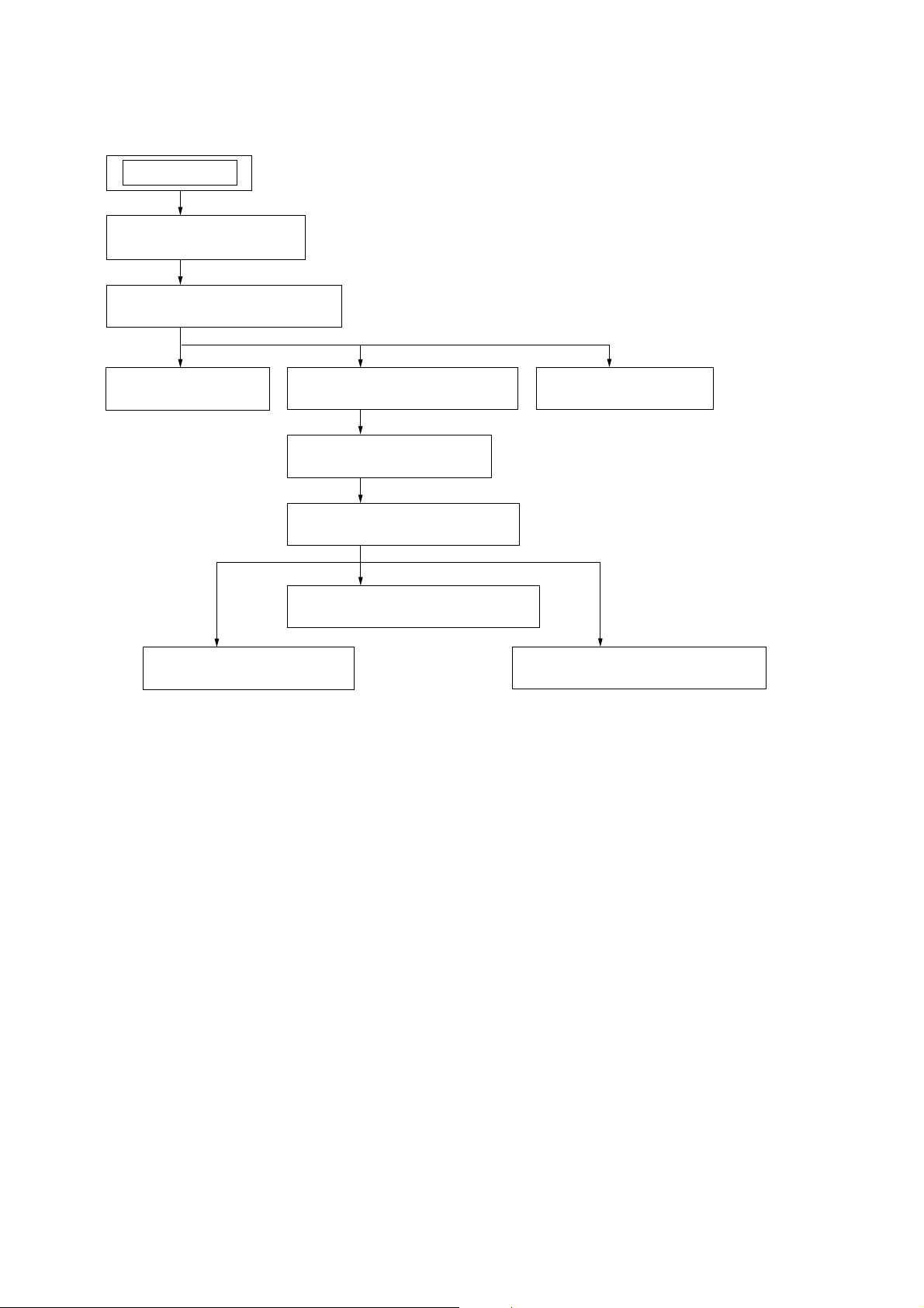
SECTION 2
DISASSEMBLY
Note : This set can be disassemble according to the following sequence.
SET
2-1. SUB PANEL ASSY
(Page 8)
2-2. CD MECHANISM BLOCK
(Page 8)
CDX-GT10M
2-3. MAIN BOARD
(Page 9)
2-7. OPTICAL PICK-UP
(Page 11)
2-4. CHASSIS (T) SUB ASSY
(Page 9)
2-5. ROLLER ARM ASSY
(Page 10)
2-6. CHASSIS (OP) ASSY
(Page 10)
2-8. SL MOTOR ASSY (M902)
(Page 11)
2-10. SERVO BOARD
(Page 12)
2-9. LE MOTOR ASSY (M903)
(Page 12)
7
CDX-GT10M
s
)
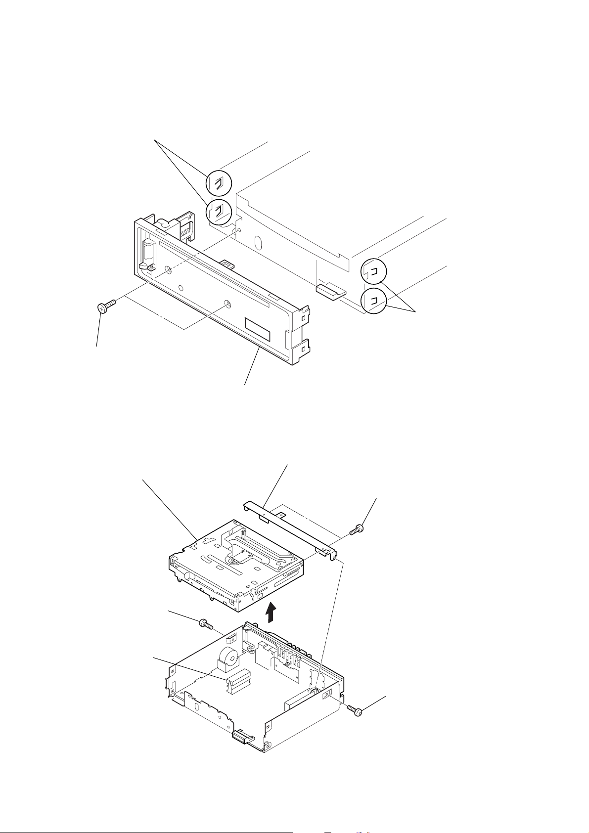
Note : Follow the disassembly procedure in the numerical order given.
2-1. SUB PANEL ASSY
3
two claws
1
two
screws
(+PTT 2.6
×
6)
2-2. CD MECHANISM BLOCK
7
CD mechanism block
4
sub panel assy
6
bracket (CD)
5
two
screws
(+PTT 2.6
2
two claw
×
4)
2
screw
(+PTT 2.6
4
CNP301
×
6)
3
1
screw
(+PTT 2.6
×
6
8
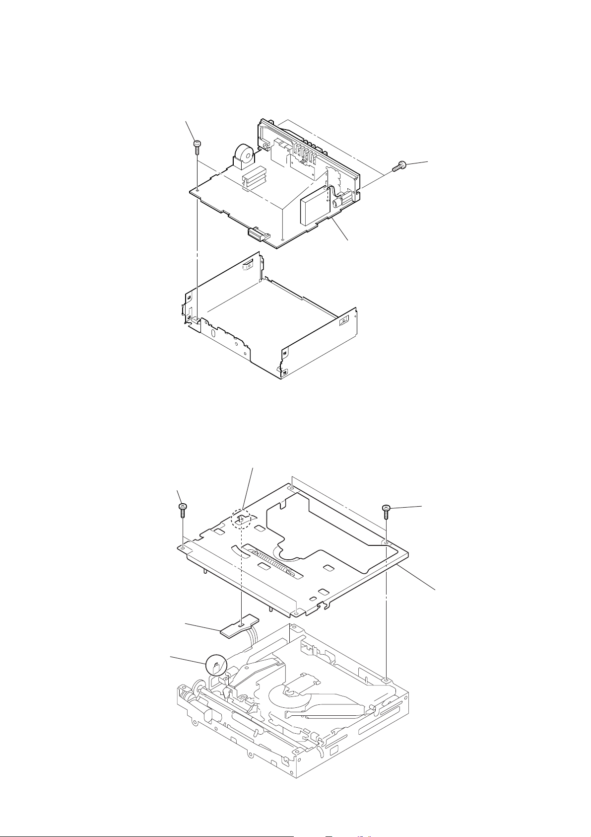
2-3. MAIN BOARD
1
(+BTT 2.6
three
screws
×
CDX-GT10M
5)
2
two
screws
×
8)
3
MAIN board
(+PTT 2.6
2-4. CHASSIS (T) SUB ASSY
2
two
screws
(+P 1.7
5
SENSOR board
3
claw
×
2.2)
4
claw
1
two
screws
×
(+P 1.7
6
2.2)
chassis (T) sub assy
9
CDX-GT10M
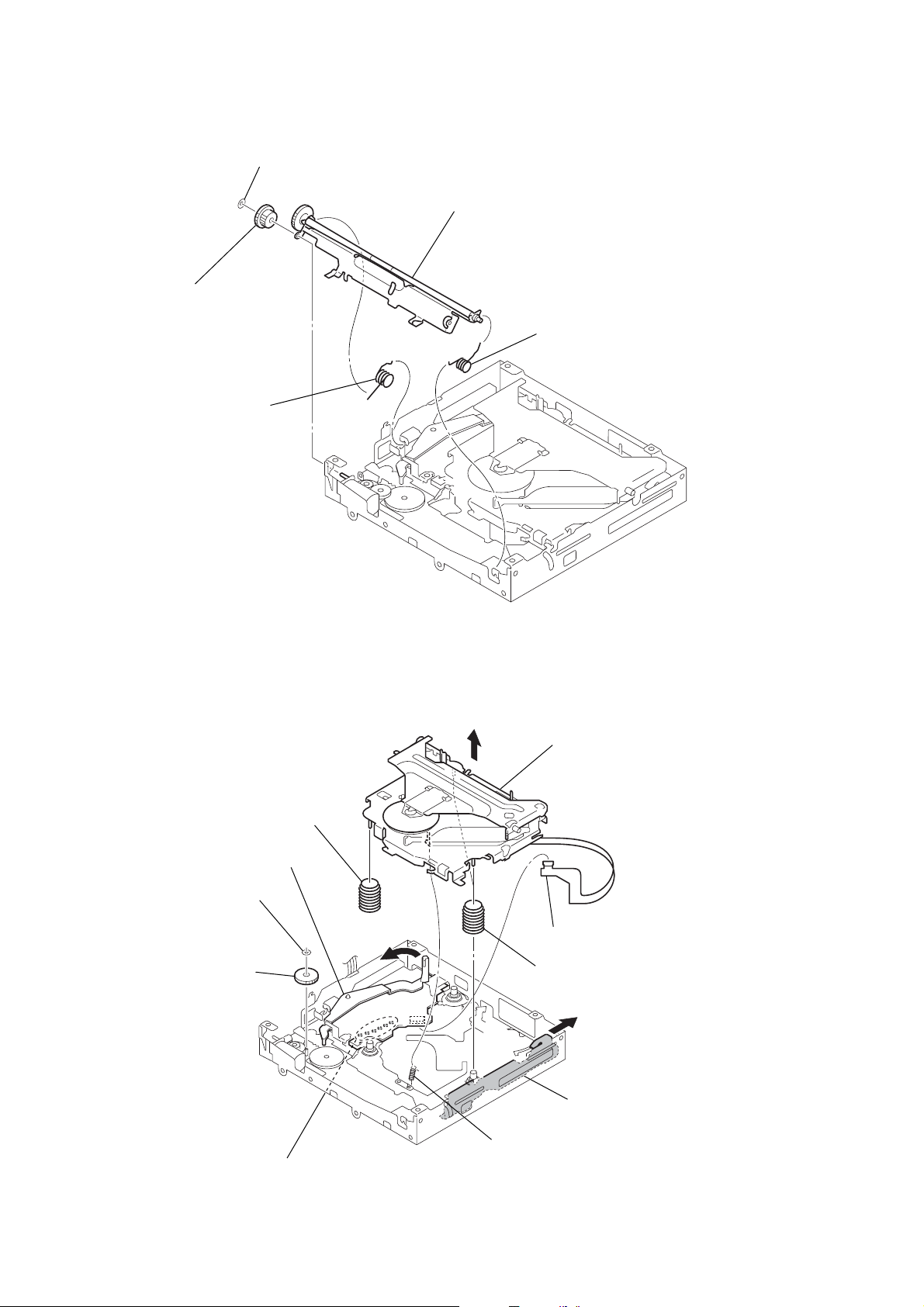
2-5. ROLLER ARM ASSY
4
gear (RA1)
1
spring (RAL)
3
washer (1.1-2.5)
5
roller arm assy
2
spring (RAR)
2-6. CHASSIS (OP) ASSY
0
coil spring (damper)
4
washer
5
gear (LE1)
lever (D)
6
8
qa
chassis (OP) assy
1
CN2
9
two coil springs (damper)
7
slider (R)
10
2
Remove the six solders.
3
tension spring (KF60)
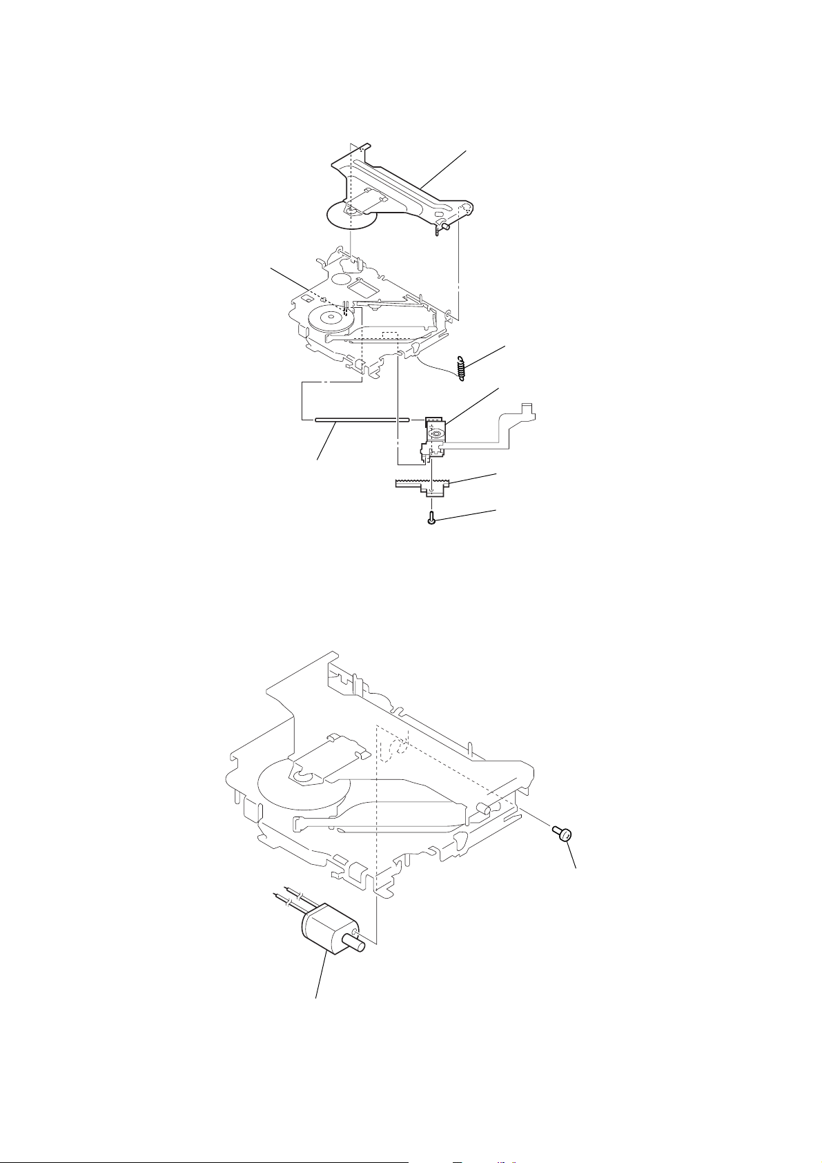
2-7. OPTICAL PICK-UP
)
)
5
claw
2
chucking arm sub assy
1
tension coil spring (CHKG
7
optical pick-up
CDX-GT10M
2-8. SL MOTOR ASSY (M902)
6
main shaft
4
rack (SL)
3
screw
(+B 1.4
×
5)
2
SL motor assy (M902)
1
screw
(+P 1.4
×
1.8
11
CDX-GT10M
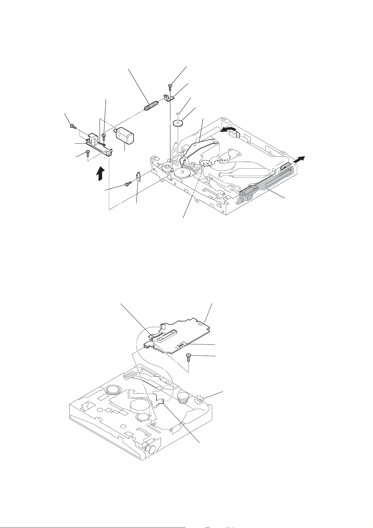
2-9. LE MOTOR ASSY (M903)
qf
two toothed lock
(+M 1.4
bracket (LEM-N)
qs
(+M 1.7
screw
×
)
screws
2.5)
6
screw
(+P 1.7
×
qd
2.2)
qa
screw
(+M 1.7
0
gear (LE) assy
×
2.5)
qg
LE motor assy
(M903)
7
leaf spring (LE)
8
screw
(+M 1.7
9
2
×
bearing (LEB-N)
washer
3
gear (LE1)
lever (D)
2.5)
4
5
slider (R)
2-10. SERVO BOARD
1
Remove the eight solders.
1
Remove the solders.
6
2
4
(M 1.7
SERVO board
Remove the three solders.
toothed lock
5
claw
×
screw
2.5)
12
3
CN2 (16P)
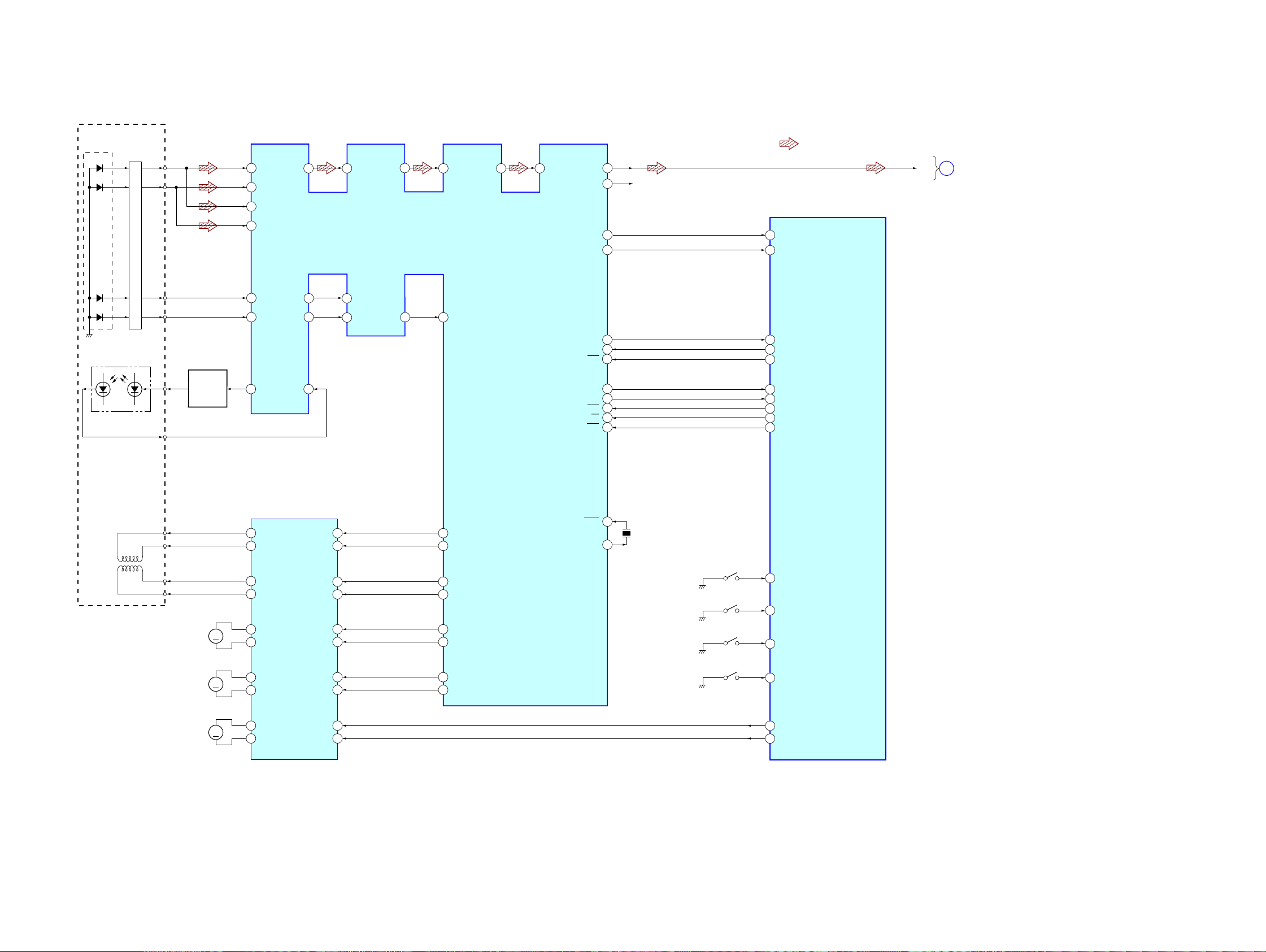
3-1. BLOCK DIAGRAM — CD SECTION —
DETECTOR
PD1
PD2
PD1
PD2
I-V AMP
A
82
B
84
C
83
D
85
SECTION 3
DIAGRAMS
RFO
78
CDX-GT10M
• R-ch is omitted due to same as L-ch.
• Siganal Path
: CD
AGCO
AGCI
77
76
RF AMP,DIGITAL SERVO,
DIGITAL SIGNAL PROCESSOR
71
IC1
EFM
RFI
68
ASY
69
LOUT
ROUT
LMUTE
RMUTE
20
16
R-CH
30
29
CD_MUTE-L
94
CD_MUTE-R
93
CD-L
MAIN
A
SECTION
(Page 14)
E
F
LASER DIODE
PICK-UP BLOCK
(KSS1000E)
2-AXIS DEVICE
(FOCUS)
(TRACKING)
PD LD
MON OUT
OPTICAL
FCS+
FCS–
TRK+
TRK–
E
F
LD
AUTOMATIC
POWER
CONTROL
M902
(SLED)
Q1
M
87
86
1
FOCUS/TRACKING COIL DRIVE,
11
12
13
14
15
16
FEO
E
F
LD
SLED/SPINDLE/LOADING
VO2–
VO2+
VO1–
VO1+
VO4+
VO4–
93
TEO
96
2
PD
MOTOR DRIVE
IC2
OPIN2+
OPIN2–
OPIN1+
OPIN1–
OPIN4+
OPIN4–
FE–
92
TE2
TE–
95
5
6
2
3
27
26
97
TEC
98
12
SO
13
SI
11
SCK
6
RFOK
7
INTQ
10
STB
9
A0
8
RST
23
FD+
52
FD–
53
TD+
54
TD–
55
SD+
56
SD–
57
XTAL
XTAL
24
X1
16.9344MHz
SW1
(DOWN)
SW2
(SELF)
SW3
(DISC IN)
CD_SI
18
CD_SO
19
CD_SCK
20
CD_RFOK
89
INTQ
55
CD_STB
92
CD_A0
91
CD_RST
90
CD_DSW
99
CD_SELFSW
96
CD_INSW
95
SYSTEM CONTROL
IC501 (1/3)
CDX-GT10M
M901
(SPINDLE)
M903
(LOADING)
OPIN3+
OPIN3–
FWD
REV
24
23
1
28
17
M
M
VO3+
18
VO3–
10
VOL+
9
VOL–
MD+
58
MD–
59
SW4
(LIMIT)
100
97
98
CD_LIMIT
CD_LM_LO
CD_LM_EJ
13 13
CDX-GT10M
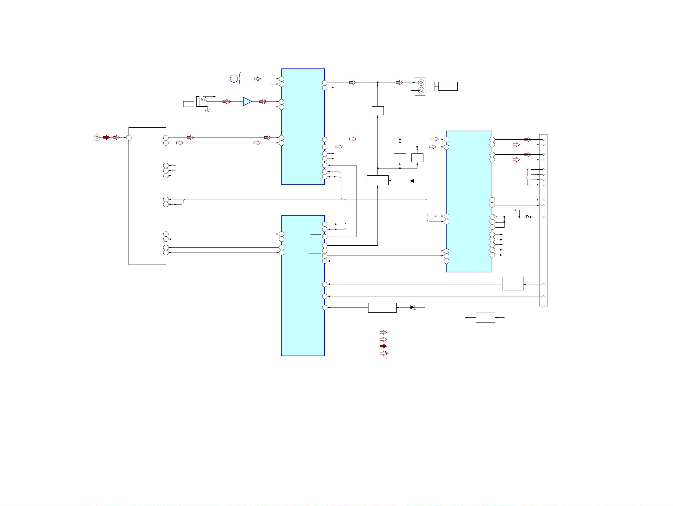
3-2. BLOCK DIAGRAM — MAIN SECTION —
ELECTRONIC VOLUME
IC401
J1
(ANTENNA)
1
ANT
TU1
(TUNER UNIT)
TU VDD
E2P VDD
TU-SCL
TU-SDA
S-METER
TU MUTE
E2P SCL
E2P SDA
L-CH
R-CH
VCC
10
11
15
13
14
16
17
4
3
6
7
J901
AUX
AUDIO+8.3V
TU+5V
BU+3.3V
SCL
SDA
CD
SECTION
(Page 13)
R-CH
CD-L
A
AUX
BUFFER
IC901
R-CH
R-CH
9
CD LCH
8
CD RCH
5
AUX LCH
3
AUX RCH
7
TU LCH
6
TU RCH
SYSTEM CONTROL
39
VSM
12
TUATT
25
EEP CKO
24
EEP SIO
OUT SUB-L
OUT SUB-R
IC501 (2/3)
OUT FL
OUT RL
OUT FR
OUT RR
MUTE
SCL
SDA
I2C CKO
I2C SIO
VO ATT
ATT
BEEP
AMPSTB
DIAG
17
18
23
22
25
24
29
30
31
33
34
9
86
5
26
8
R-CH
R-CH (FRONT)
R-CH (REAR)
SCL
SDA
SCL
SDA
MUTE
Q481
MUTE DRIVE
Q478,479
MUTE
Q441
R-CH
D479
MUTE
Q461
BATT
J330
L
AUDIO OUT
REAR
R
I2C-BUS CONTROLLED
POWER AMP/MULTIPLE
VOLTAGE REGULATOR
SDA
SCL
IC750
12
IN FL
11
IN RL
2
SDA
4
SCL
16
BEEP
22
STB
25
DIAG
OUT FL+
OUT FL–
OUT RL+
OUT RL–
AMP-REM
ANT-REM
VP1
VP2
AUDIO8.3V
B.UP+B
SERVO3.3V
MECHA6V
PANEL+B
5
3
9
7
R-CH
29
27
BATT
VP
35
20
6
30
AUDIO+8.3V
37
BU+3.3V
31
SERVO+3.3V
33
MECHA+6V
34
PANEL+B
FU601
CN601
10
12
11
16
1
FL+
9
FL–
2
RL+
RL–
4
FR+
FR–
3
RR+
RR–
5
AMP-REM
6
ANT-REM
BATT
ACC IN
TESTIN
BUIN
ACCESSORY
72
73
54
BATTERY CHECK
Q580-582
• R-CH is omitted due to same as L-CH.
• Signal Path
: CD PLAY
: FM
: AM
: AUX
D580,581
BATT
TU+5V
TU+5V REG
Q1
CHECK
Q631
AUDIO+8.3V
7
ACC
15
TEST
CDX-GT10M
1414
CDX-GT10M
t
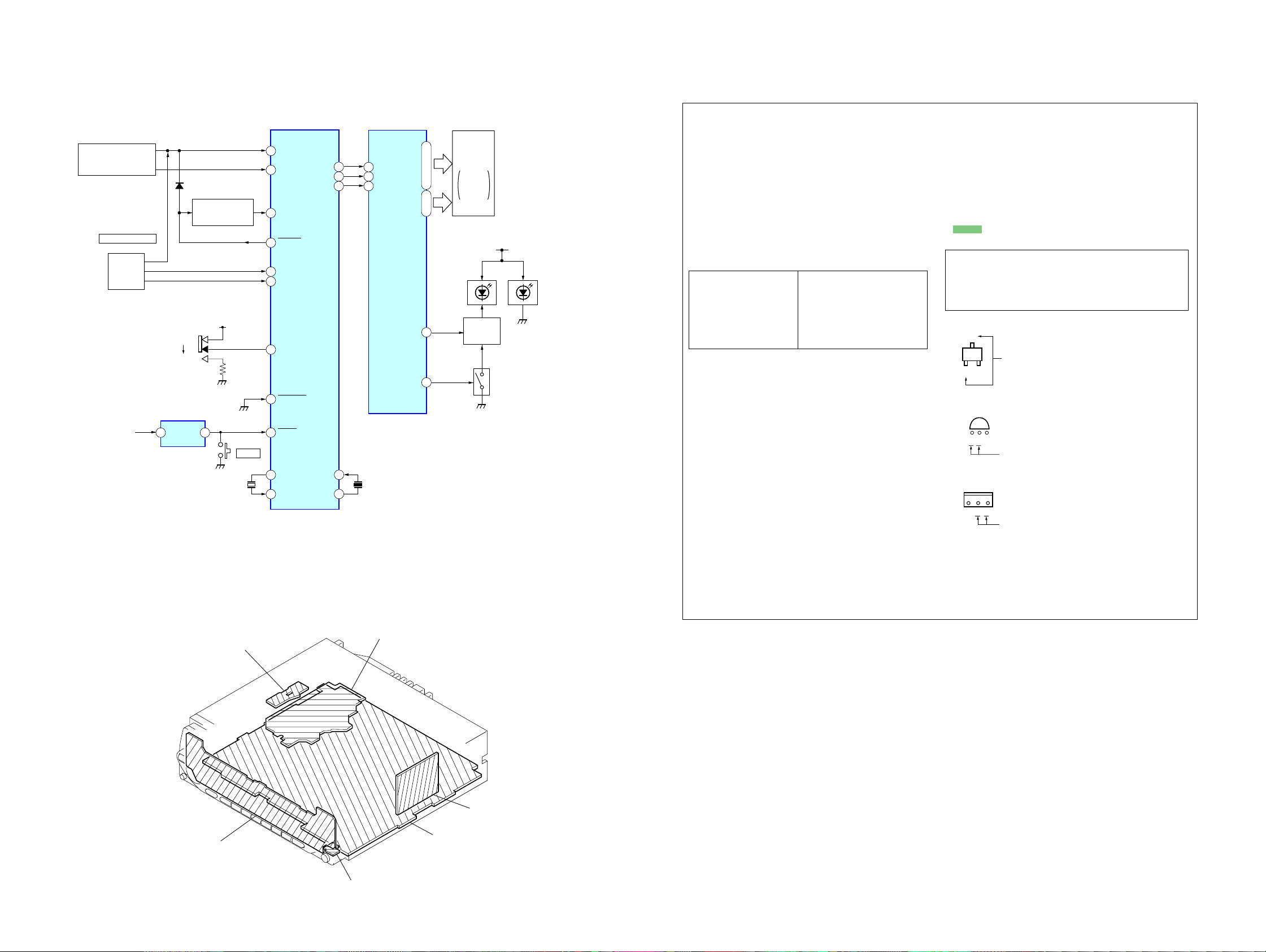
3-3. BLOCK DIAGRAM — DISPLAY SECTION —
SYSTEM CONTROL
IC501 (3/3)
KEY MATRIX
LSW901–903,909,910,920
S908,911–919
RE901
PUSH DIAL SELECT
(VOLUME)
ROTARY
ENCODER
S502
FREQUENCY
()
SELECT
BU+3.3V
D503
KEY ACKNOWLEDGE
10K
9K
RESET
IC602
2 1
VDD VOUT
SWITCH
Q664
BU+3.3V
X502
32.768kHz
S702
RESET
41
40
52
76
31
32
3
7
77
79
80
KEYIN0
KEYIN1
KEY ACK
XKEY ON
RE-IN0
RE-IN1
AREASEL0
NOSE DET
RESET
XOUT
XIN
LCD SO
LCD CKO
LCD CE
OSC IN
OSC OUT
3-4. CIRCUIT BOARDS LOCATION
• NOTE FOR PRINTED WIRING BOARDS AND SCHEMATIC DIAGRAMS
LCD DRIVER
IC901
5
|
S1
50
28
64
DI
29
27
82
83
CL
63
CE
62
X501
18.432MHz
S48
COM4
|
COM1
DIMMER
BACK LIGHT
|
•
55
•
60
51
|
54
2
1
LCD901
LIQUID
CRYSTAL
DISPLAY
PANEL
PANEL+B
LED932
LCD BACK
()
LIGHT
DIMMER
LED DRIVE
Q931
LCD BACK LIGHT
LED DRIVE
Q932
LED908,
911–919,941–944,951
LSW901–903,909,910,920
THIS NOTE IS COMMON FOR PRINTED WIRING
BOARDS AND SCHEMATIC DIAGRAMS.
(In addition to this, the necessary note is printed
in each block.)
For schematic diagrams.
Note:
• All capacitors are in µF unless otherwise noted. (p: pF)
50 WV or less are not indicated except for electrolytics
and tantalums.
• All resistors are in Ω and 1/
specified.
f
•
: internal component.
4
W or less unless otherwise
• C : panel designation.
Note:
The components identified by mark 0 or dotted
line with mark 0 are criti-
cal for safety.
Replace only with part
number specified.
Note:
Les composants identifiés par
une marque 0 sont critiques
pour la sécurité.
Ne les remplacer que par une
piéce portant le numéro
spécifié.
• A : B+ Line.
• B : B– Line.
• H : adjustment for repair.
•Voltages and waveforms are dc with respect to ground
under no-signal (detuned) conditions.
• CD mechanism section
no mark : CD PLAY
• Main (1/3), (2/3), (3/3) and Key sections
no mark : FM
(): AM
<>: CD PLAY
∗ : Impossible to measure
•Voltages are taken with a VOM (Input impedance 10 MΩ).
Voltage variations may be noted due to normal production tolerances.
•Waveforms are taken with a oscilloscope.
Voltage variations may be noted due to normal production tolerances.
• Circled numbers refer to waveforms.
• Signal path.
J : CD PLAY
F : FM
f : AM
L : AUX
For printed wiring boards.
Note:
• X : parts extracted from the component side.
• Y : parts extracted from the conductor side.
a
•
• : Pattern from the side which enables seeing.
(The other layers' patterns are not indicated.)
Caution:
Pattern face side: Parts on the pattern face side seen from the
(Side B) pattern face are indicated.
Parts face side: Parts on the parts face side seen from the
(Side A) parts face are indicated.
: Through hole.
C
Q
These are omitted
EB
E
CB
These are omitted
C
BE
These are omitted
CDX-GT10M
SENSOR board
KEY board
SERVO board
tuner uni
(TU1)
MAIN board
JACK board
15 15
 Loading...