

Sony CDPCX-333-ES, CDPCX-555-ES Service manual
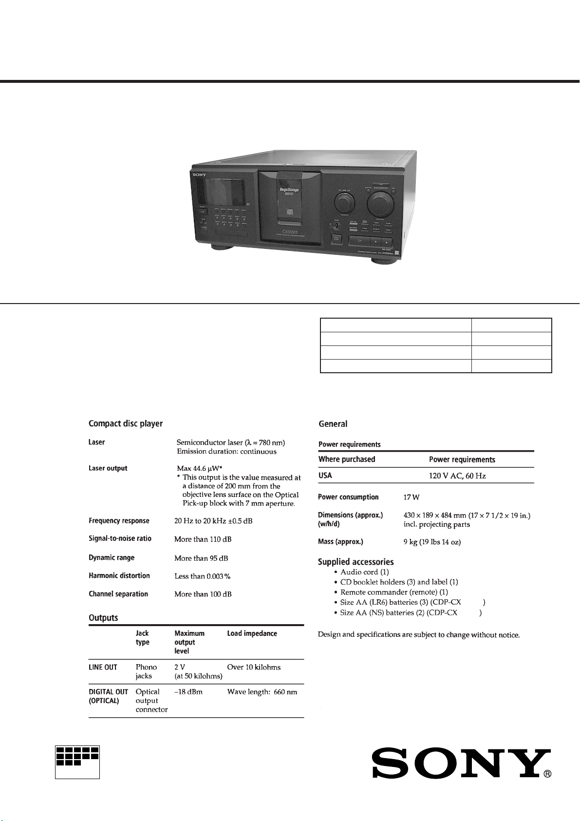
CDP-CX333ES/CX555ES
SERVICE MANUAL
Photo: CX555ES
US Model
Canadian Model
Model Name Using Similar Mechanism CDP-CX300
CD Mechanism Type CDM54-KIBD35B
Base Unit Type KSM-213BFN/C2NP
Optical Pick-up Type KSS-213B/C2N
SPECIFICATIONS
555ES
333ES
MICROFILM
COMPACT DISC PLAYER
SECTION 1
SERVICING NOTES
TABLE OF CONTENTS
1. SERVICING NOTES ............................................... 2
2. GENERAL ................................................................... 8
3. DISASSEMBLY ......................................................... 9
4. SERVICE MODE...................................................... 12
5. TEST MODE.............................................................. 16
6. MECHANICAL ADJUSTMENTS....................... 17
7. ELECTRICAL ADJUSTMENT............................ 19
8. DIAGRAMS
8-1. Block Diagram – BD Section – ..................................... 21
8-2. Block Diagram – MAIN Section – ................................ 22
8-3. Note for Printed Wiring Boards
and Schematic Diagrams ................................................ 23
8-4. Printed Wiring Board – BD Board – ............................. 24
8-5. Schematic Diagram – BD Board – ................................ 25
8-6. Printed Wiring Board – MAIN Board – ........................ 26
8-7. Schematic Diagram – MAIN Board (1/3) – .................. 28
8-8. Schematic Diagram – MAIN Board (2/3) – .................. 29
8-9. Schematic Diagram – MAIN Board (3/3) – .................. 30
8-10. Printed Wiring Board – JACK Board –......................... 31
8-11. Schematic Diagram – JACK Board – ............................ 31
8-12. Printed Wiring Board – DISPLAY Board – .................. 32
8-13. Schematic Diagram – DISPLAY Board – ..................... 33
8-14. Printed Wiring Board – JOG Board – ........................... 34
8-15. Schematic Diagram – JOG Board – .............................. 35
8-16. Printed Wiring Boards – D.SENSOR (IN)/
D.SENSOR (OUT)/SENSOR (T) Boards – ................... 36
8-17. Schematic Diagram – D.SENSOR (IN)/
D.SENSOR (OUT)/SENSOR (T) Boards – ................... 37
8-18. Printed Wiring Boards – D.MOTOR/D.SWITCH/
KEY/LED/L.T.MOTOR/L.SWITCH (A)/
L.SWITCH (B) Boards – ................................................ 38
8-19. Schematic Diagram – D.MOTOR/D.SWITCH/
KEY/LED/L.T.MOTOR/L.SWITCH (A)/
L.SWITCH (B) Boards – ................................................ 39
8-20. Printed Wiring Board – POWER Board –..................... 40
8-21. Schematic Diagram – POWER Board –........................ 41
8-22. IC Pin Function Description ........................................... 49
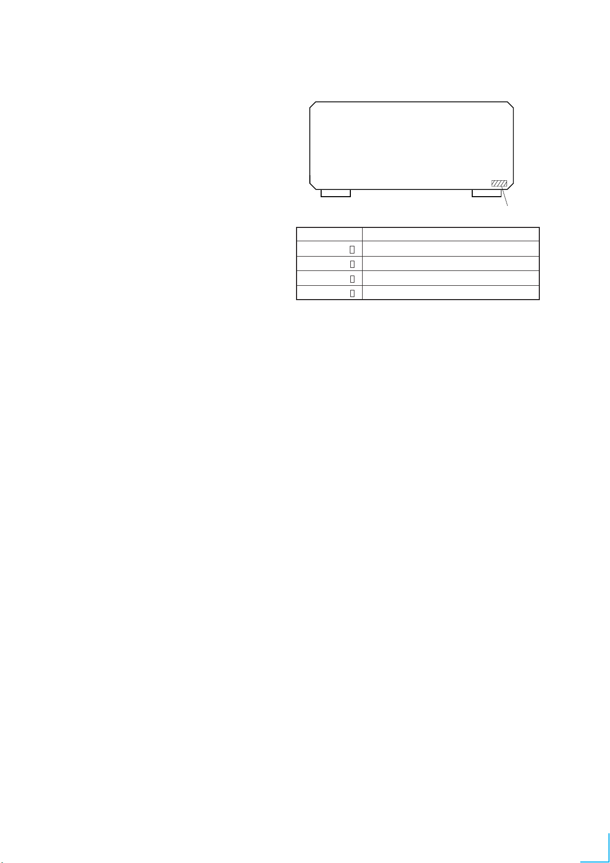
MODEL IDENTIFICATION
— BACK PANEL —
PA R T N o . MODEL
4-217-909-0
4-217-909-1
4-217-909-2
4-217-909-3
CX333ES: US model
CX333ES: Canadian model
CX555ES: US model
CX555ES: Canadian model
PART No.
9. EXPLODED VIEWS ................................................ 54
10. ELECTRICAL PARTS LIST ............................... 61
SAFETY-RELATED COMPONENT WARNING!!
COMPONENTS IDENTIFIED BY MARK ! OR DOTTED
LINE WITH MARK ! ON THE SCHEMATIC DIAGRAMS
AND IN THE PARTS LIST ARE CRITICAL TO SAFE
OPERATION. REPLACE THESE COMPONENTS WITH
SONY PARTS WHOSE PART NUMBERS APPEAR AS
SHOWN IN THIS MANUAL OR IN SUPPLEMENTS PUBLISHED BY SONY.
2
ATTENTION AU COMPOSANT AYANT RAPPORT
À LA SÉCURITÉ!
LES COMPOSANTS IDENTIFIÉS P AR UNE MARQUE !
SUR LES DIAGRAMMES SCHÉMATIQUES ET LA LISTE
DES PIÈCES SONT CRITIQUES POUR LA SÉCURITÉ
DE FONCTIONNEMENT. NE REMPLACER CES COMPOSANTS QUE PAR DES PIÈCES SONY DONT LES
NUMÉROS SONT DONNÉS DANS CE MANUEL OU
DANS LES SUPPLÉMENTS PUBLIÉS PAR SONY.
SAFETY CHECK-OUT
After correcting the original service problem, perform the following safety check before releasing the set to the customer:
Check the antenna terminals, metal trim, “metallized” knobs,
screws, and all other exposed metal parts for AC leakage.
Check leakage as described below.
LEAKAGE TEST
The AC leakage from any exposed metal part to earth ground and
from all exposed metal parts to any exposed metal part having a
return to chassis, must not exceed 0.5 mA (500 microamperes).
Leakage current can be measured by any one of three methods.
1. A commercial leakage tester , such as the Simpson 229 or RCA
WT -540A. Follo w the manufacturers’ instructions to use these
instruments.
2. A battery-operated AC milliammeter. The Data Precision 245
digital multimeter is suitable for this job.
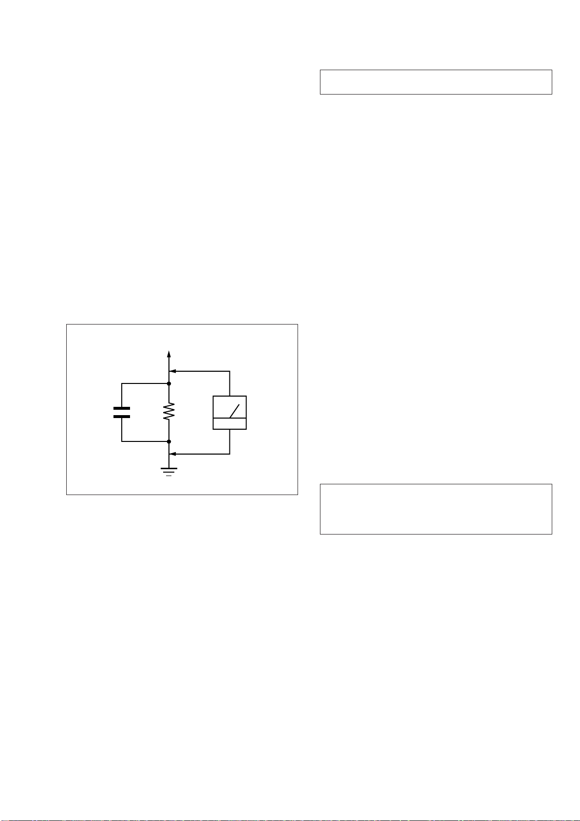
3. Measuring the voltage drop across a resistor by means of a
VOM or battery-operated AC voltmeter. The “limit” indication is 0.75 V, so analog meters must have an accurate lowvoltage scale. The Simpson 250 and Sanwa SH-63Trd are examples of a passive VOM that is suitable. Nearly all battery
operated digital multimeters that have a 2 V A C range are suitable. (See Fig. A)
To Exposed Metal
Parts on Set
NOTES ON HANDLING THE OPTICAL PICK-UP
BLOCK OR BASE UNIT
The laser diode in the optical pick-up block may suffer electrostatic break-down because of the potential difference generated
by the charged electrostatic load, etc. on clothing and the human
body.
During repair, pay attention to electrostatic break-down and also
use the procedure in the printed matter which is included in the
repair parts.
The flexible board is easily damaged and should be handled with
care.
NOTES ON LASER DIODE EMISSION CHECK
The laser beam on this model is concentrated so as to be focused
on the disc reflective surface by the objective lens in the optical
pick-up block. Therefore, when checking the laser diode emission, observe from more than 30 cm away from the objective lens.
LASER DIODE AND FOCUS SEARCH OPERATION
CHECK
Carry out the “S curve check” in “CD section adjustment” and
check that the S curve waveforms is output three times.
Notes on chip component replacement
• Never reuse a disconnected chip component.
• Notice that the minus side of a tantalum capacitor may be damaged by heat.
AC
1.5 k
0.15 µF
Fig. A. Using an AC voltmeter to check AC leakage.
Ω
Earth Ground
voltmeter
(0.75 V)
Flexible Circuit Board Repairing
• Keep the temperature of the soldering iron around 270 ˚C during repairing.
• Do not touch the soldering iron on the same conductor of the
circuit board (within 3 times).
• Be careful not to apply force on the conductor when soldering
or unsoldering.
CAUTION
Use of controls or adjustments or performance of procedures
other than those specified herein may result in hazardous radiation exposure.
3

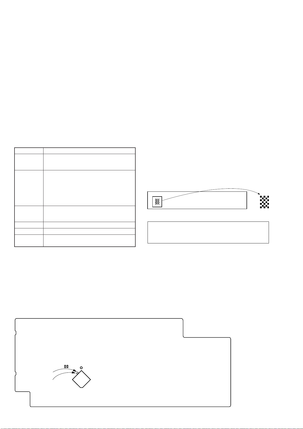
CD-TEXT TEST DISC
This unit is able to display the TEXT data (character information) written in the CD on its fluorescent indicator tube.
The CD-TEXT TEST DISC (TGCS-313:J-2501-126-A) is used for checking the display.
To check, perform the following procedure.
Checking Method:
1. Turn ON the power, set the disc on the disc table with the side labeled as “test disc” as the right side, close the front cover, and chuck
the disc.
2. The following will be displayed on the fluorescent indicator tube. (The display switches each time the [TIME/TEXT] button is pressed.)
Display: CD TEXT TEST DISC (Album Title)
3. Press the [] button and play back the disc.
4. The following will be displayed on the fluorescent indicator tube. (If nothing is displayed, press the [TIME/TEXT] button.)
5. Rotate [AMS] knob to switch the track. The text data of each track will be displayed.
For details of the displayed contents for each track, refer to “Table 1: CD-TEXT TEST DISC Text Data Contents” and “Table 2: CDTEXT TEST DISC Recorded Contents and Display”.
Restrictions in CD-TEXT Display
In this unit, some special characters will not be displayed properly. These will be displayed as a space or a character resembling it. For
details, refer to “Table 2: CD-TEXT DISC Recorded Contents and Display”.
Table 1: CD-TEXT TEST DISC Text Data Contents (TRACKS No. 1 to 41:Normal Characters)
·
Display: 1 kHz/0 dB/ L&R
≠ ±
TRACK
No.
1
2
3
4
5
6
7
8
9
10
11
12
13
14
15
16
17
18
19
20
21
Note: The contents of Track No. 1 to 41 are the same as those of the current TEST DISC-their titles are displayed.
1 kHz/0 dB/L&R
20 Hz/0 dB/L&R
40 Hz/0 dB/L&R
100 Hz/0 dB/L&R
200 Hz/0 dB/L&R
500 Hz/0 dB/L&R
1 kHz/0 dB/L&R
5 kHz/0 dB/L&R
7 kHz/0 dB/L&R
10 kHz/0 dB/L&R
16 kHz/0 dB/L&R
18 kHz/0 dB/L&R
20 kHz/0 dB/L&R
1 kHz/0 dB/L&R
1 kHz/-1 dB/L&R
1 kHz/-3 dB/L&R
1 kHz/-6 dB/L&R
1 kHz/-10 dB/L&R
1 kHz/-20 dB/L&R
1 kHz/-60 dB/L&R
1 kHz/-80 dB/L&R
Displayed Contents
TRACK
No.
22
23
24
25
26
27
28
29
30
31
32
33
34
35
36
37
38
39
40
41
Displayed Contents
1 kHz/-90 dB/L&R
Infinity Zero w/o emphasis//L&R
Infinity Zero with emphasis//L&R
400 Hz+7 kHz(4:1)/0 dB/L&R
400 Hz+7 kHz(4:1)/-10 dB/L&R
19 kHz+20 kHz(1:1)/0 dB/L&R
19 kHz+20 kHz(1:1)/-10 dB/L&R
100 Hz/0 dB/L*
1 kHz/0 dB/L*
10 kHz/0 dB/L*
20 kHz/0 dB/L*
100 Hz/0 dB/R*
1 kHz/0 dB/R*
10 kHz/0 dB/R*
20 kHz/0 dB/R*
100 Hz Squer Wave//L&R
1 kHz Squer Wave//L&R
1 kHz w/emphasis/-0.37 dB/L&R
5 kHz w/emphasis/-4.53 dB/L&R
16 kHz w/emphasis/-9.04 dB/L&R
4
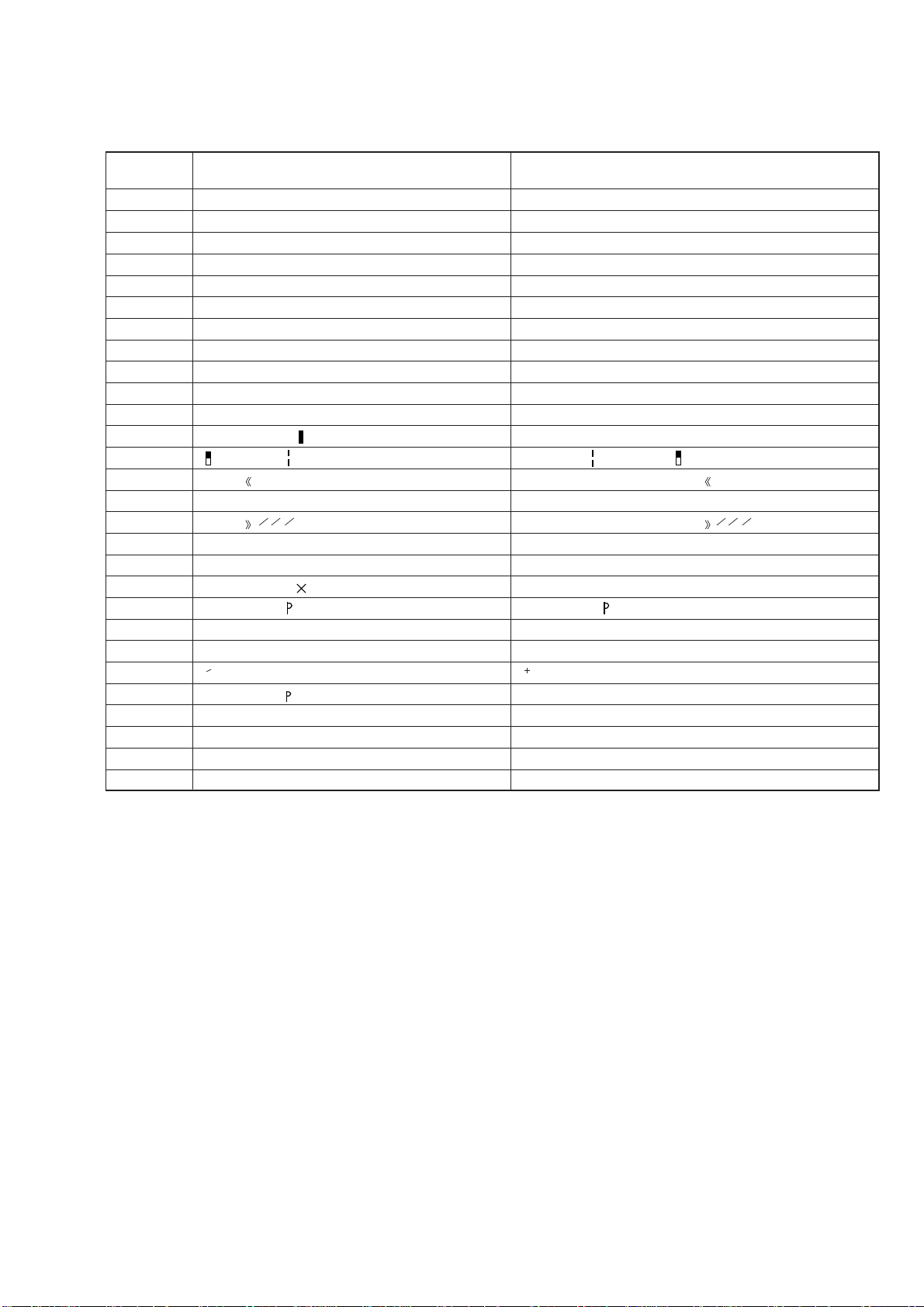
Table 2: CD-TEXT TEST DISC Recorded Contents and Display
(In this unit, some special characters cannot be displayed. This is no a fault.)
TRACK
No.
42
43
44
45
46
47
48
49
50
51
52
53
54
55
56
57
58
59
60
61
62
63
64
65
66
67
to
99
Recorded Contents
! ” # $ % & ´ (21h to 27h) 1kHz 0dB L&R
( )*+ , – . / (28h to 2Fh)
01234567 (30h to 37h)
8 9 : ; < = > ? (38h to 3Fh)
@A B C D E F G (40h to 47h)
H I J K L M N O (48h to 4Fh)
P Q R S T U V W (50h to 57h)
X Y Z [ ¥ ] ^ _ (58h to 5Fh)
a b c d e f g (60h to 67h)
′
h i j k l m n o (68h to 6Fh)
p q r s t u v w (70h to 77h)
x y z { I } ~ (78h to 7Fh)
i ¢ £ ¤ ¥ § (A0h to A7h) 8859-1
¬
≥ C ª
23
•±
†1º ¿ (B8h to BFh)
–
PR
′µ ¶ • (B0h to B7h)
113
424
(A8h to AFh)
АБВГДЕЖЗ (C0h to C7h)
И Й К Л М Н О П (C8h to CFh)
DСТУФХЦ (D0h to D7h)
ШЩЪЫЬY Я (D8h to DFh)
à á â ã ä å æ ç (E0h to E7h)
è é ê ë ì í î ï (E8h to FFh)
∂ стуфхц÷ (F0h to F7h)
шщъыьy я (F8h to FFh)
No.66
No.67
to
No.99
Displayed Contents
N All the same
N All the same
N All the same
N All the same
N All the same
N All the same
N All the same
X Y Z [ \ ] ^ _ (58····
N All the same
N All the same
N All the same
x y z { I } ~ (78····
i ¢ £ ¤ ¥ § (A0···· is not displayed
≥ (A8···· C ª ¬ PR–are not displayed
′ µ • (B0····
† ¿ (B8····1º are not displayed
•±23
113
424
¶ are not displayed
N All the same
N All the same
N All the same
Φ Ù Ú Û Ü Y ß (D8····
N All the same
N All the same
oстуфхц÷ (F0····
N All the same
N All the same
N All the same
to
N All the same
5
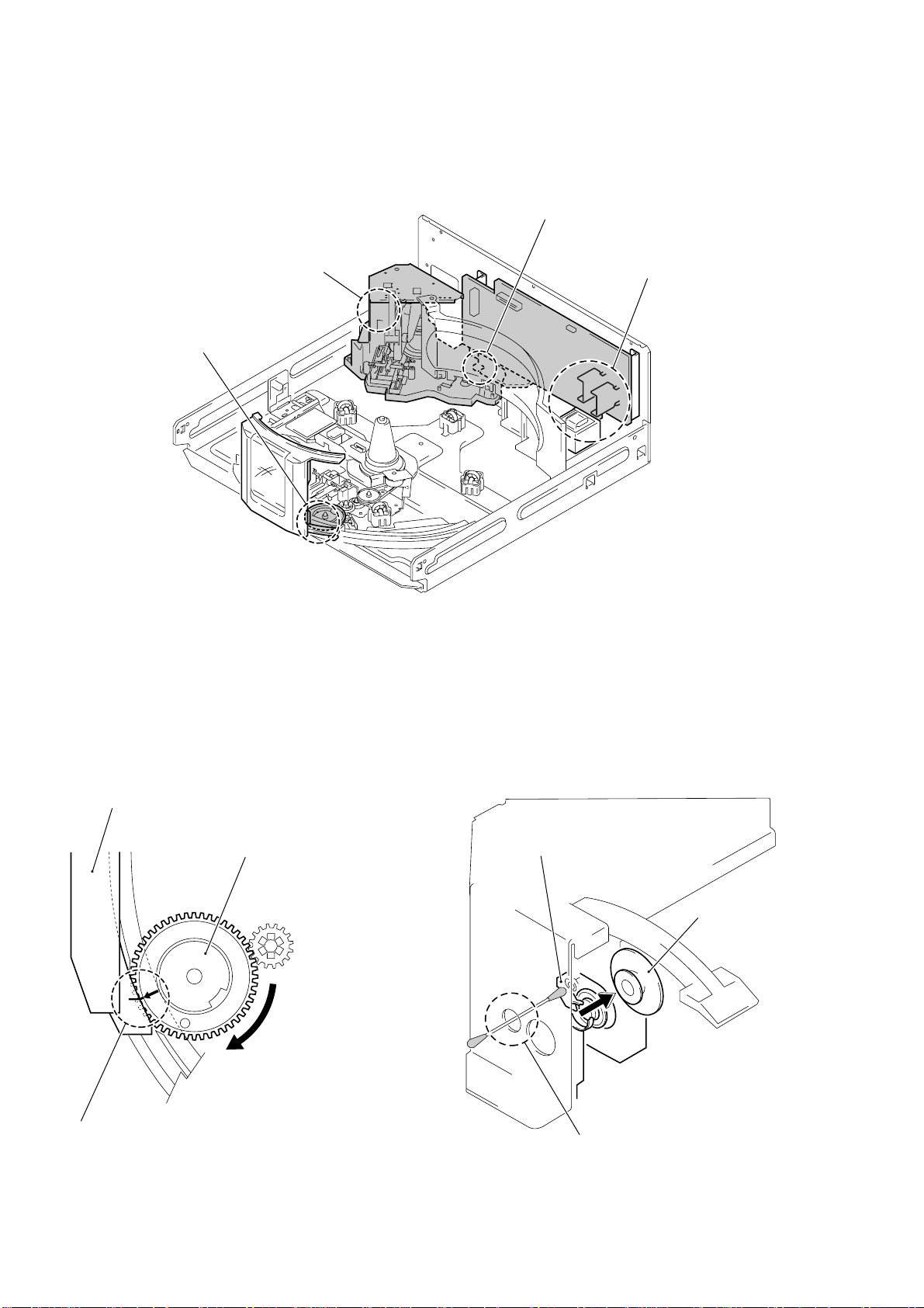
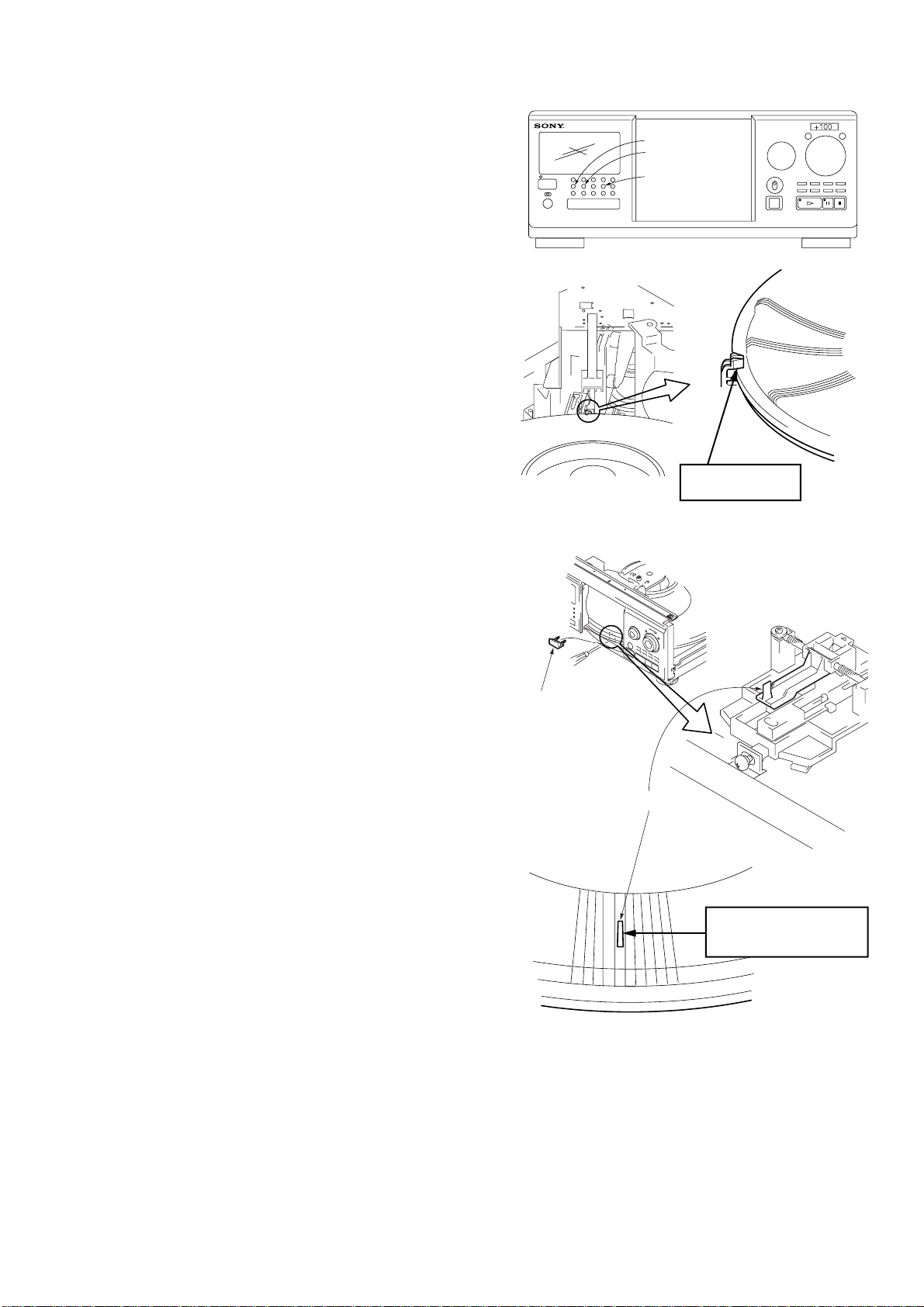
PRECAUTIONS AT SERVICING
y
Handling of wires
(loading motor). (Fig. 3)
Cleaning of optical
pick-up. (Fig. 2)
Alignment of door
drive gear phase.
(Fig. 1)
Destruction of IC due
to shortcircuit. (Fig. 4)
ALIGNMENT OF DOOR DRIVE GEAR
PHASE WITH DOOR (CD) (Fig. 1)
door (CD)
door drive gear
Align a slit of door (CD) with a marking on
the bottom land of gear tooth when the gear
is rotated fully in arrow direction, as shown.
CLEANING OF OPTICAL PICK-UP (Fig. 2)
optical pick-up
magnet assembl
Remove the magnet assembly, and
clean the lens of optical pick-up
through this hole.
6
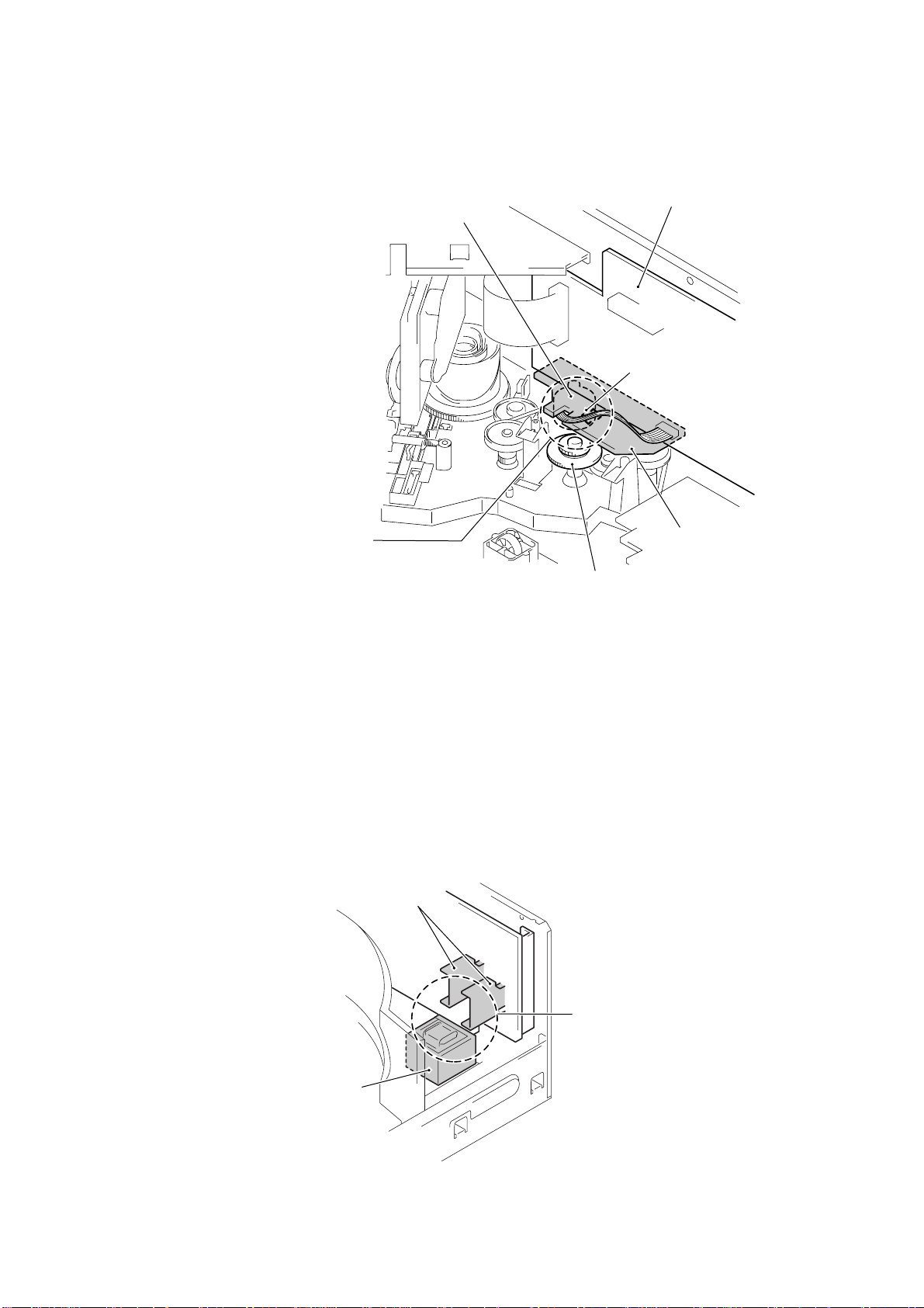
HANDLING OF WIRES (LOADING MOTOR) (Fig. 3)
When assembling this set after
service, let the wires connected
from loading motor to MAIN board
through a notch of JACK board
and clamp with a lead pin so that
they are not caught in by the gear
(table).
loading motor
MAIN board
lead pin
JACK board
gear (table)
DESTRUCTION OF IC DUE TO SHORTCIRCUIT (Fig. 4)
In removing or mounting the back panel or MAIN board with
the power supplied, an accidental shortcircuit of heatsink to
the power transformer could destroy the IC on heatsink.
heatsink
Power
transformer
Be careful of shortcircuit here.
7
SECTION 2
GENERAL
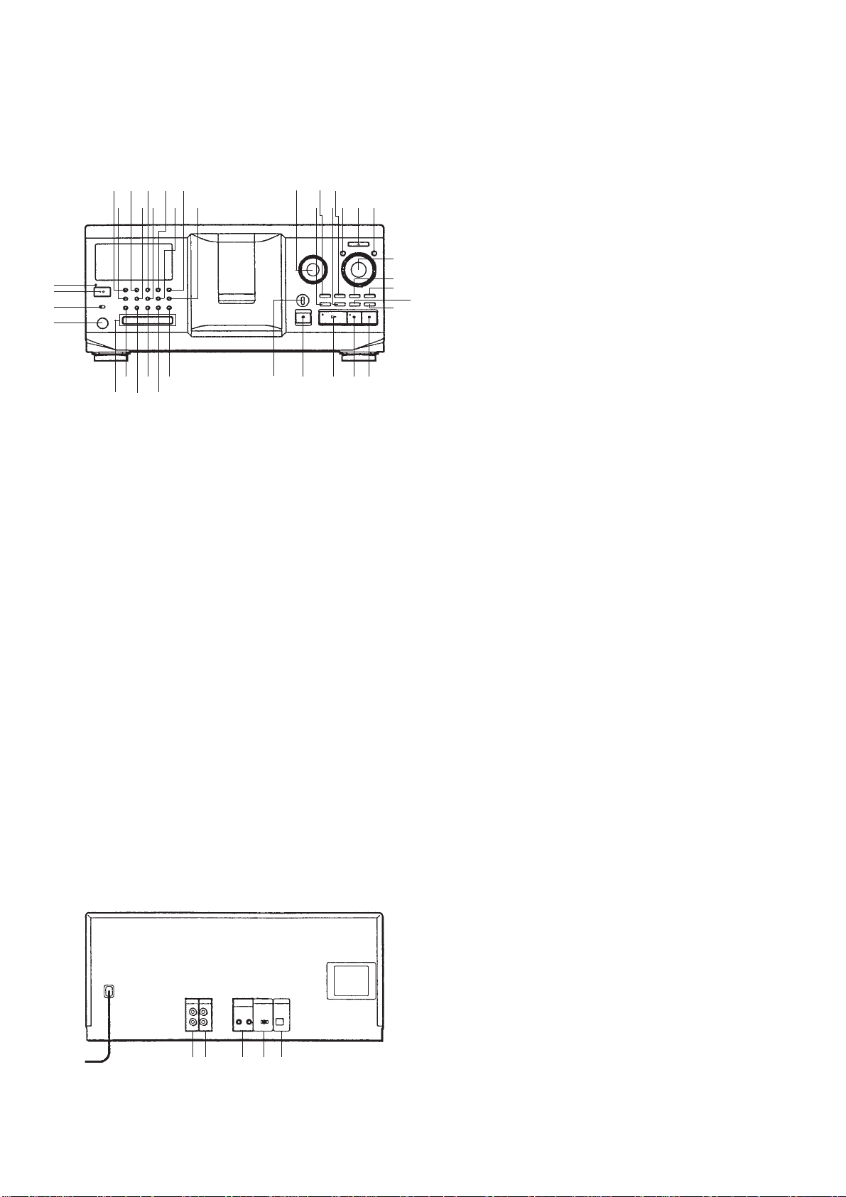
• LOCATION OF CONTROLS
– Front Panel –
9!¡
57
68
1
2
3
4
@•@ª#º#¡#™
0
!£
!™ !¢
#£
#¢
!∞!§!¶
#∞
!•
!ª
#§
@º
@¡
#¶#•
@™
@£
@¢
@∞
@¶
1 STANDBY indicator
2 1/u button
3 TIMER switch
4 KEYBOARD jack
5 CONTINUE button
6 GROUP1 button and indicator
7 SHUFFLE button
8 GROUP2 button and indicator
9 PROGRAM button
0 GROUP3 button and indicator
@§
!¡ REPEAT button
!™ GROUP4 button and indicator
!£ TIME/TEXT button
!¢ HIT LIST button and indicator
!∞ ≠AMS±, PUSH ENTER knob and button
!§ MEGA CONTROL button and indicator
!¶ EASY PLAY button and indicator
!• X-FADE button
!ª MEMO SEARCH button
@º MENU/NO button
@¡ +100 button
@™ YES button
@£ DISC/CHARACTER, PUSH ENTER knob and button
@¢ CHECK button
@∞ CLEAR button
@§ NO DELAY button
@¶ FADER button
@• IR Repeater window (CX555ES)
@ª GROUP5 button and indicator
#º GROUP6 button and indicator
#¡ GROUP7 button and indicator
#™ GROUP8 button and indicator
#£ GROUP FILE button
#¢ FILTER switch
#∞ § OPEN/CLOSE button
#§ · button and indicator
#¶ P button and indicator
#• p button
– Rear Panel –
8
12
3
4
1 2ND CD IN jack
2 LINE OUT jack
3 CONTROL A1II jack
4 COMMAND MODE CD switch
5 DIGITAL OUT OPTICAL output terminal
5
SECTION 3
r
r
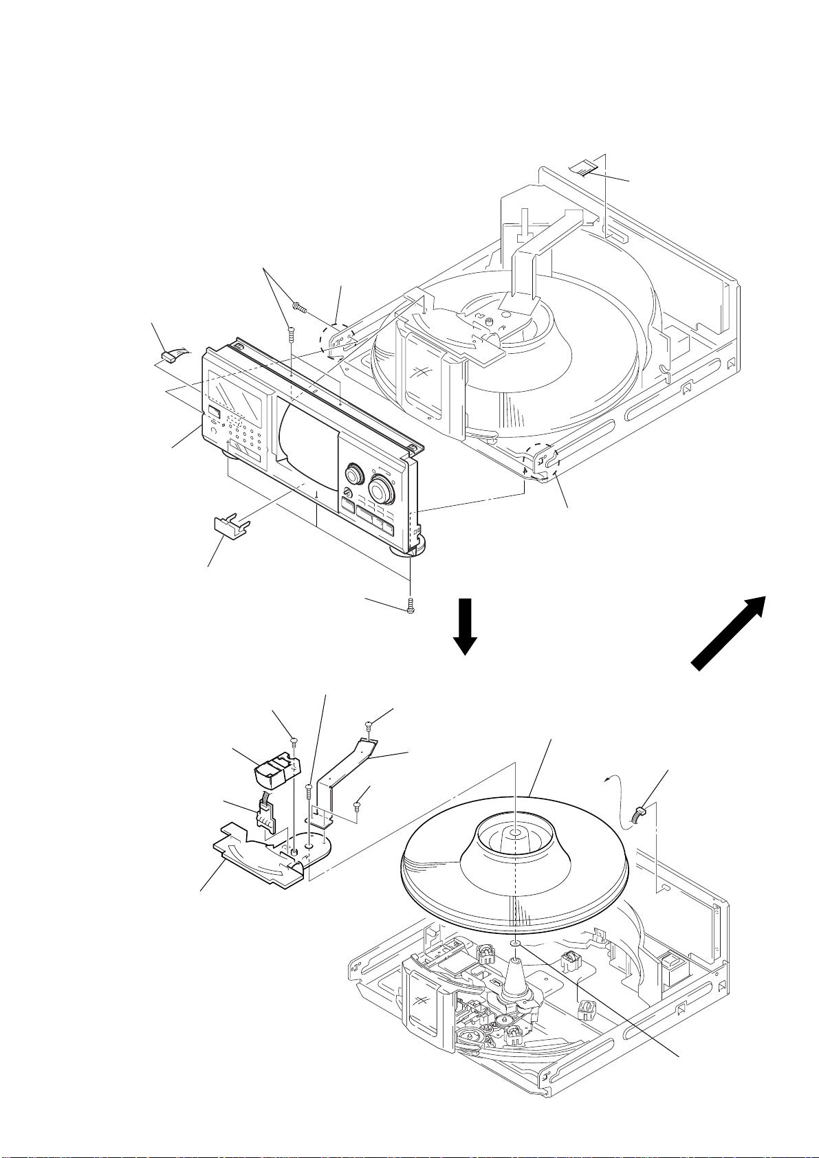
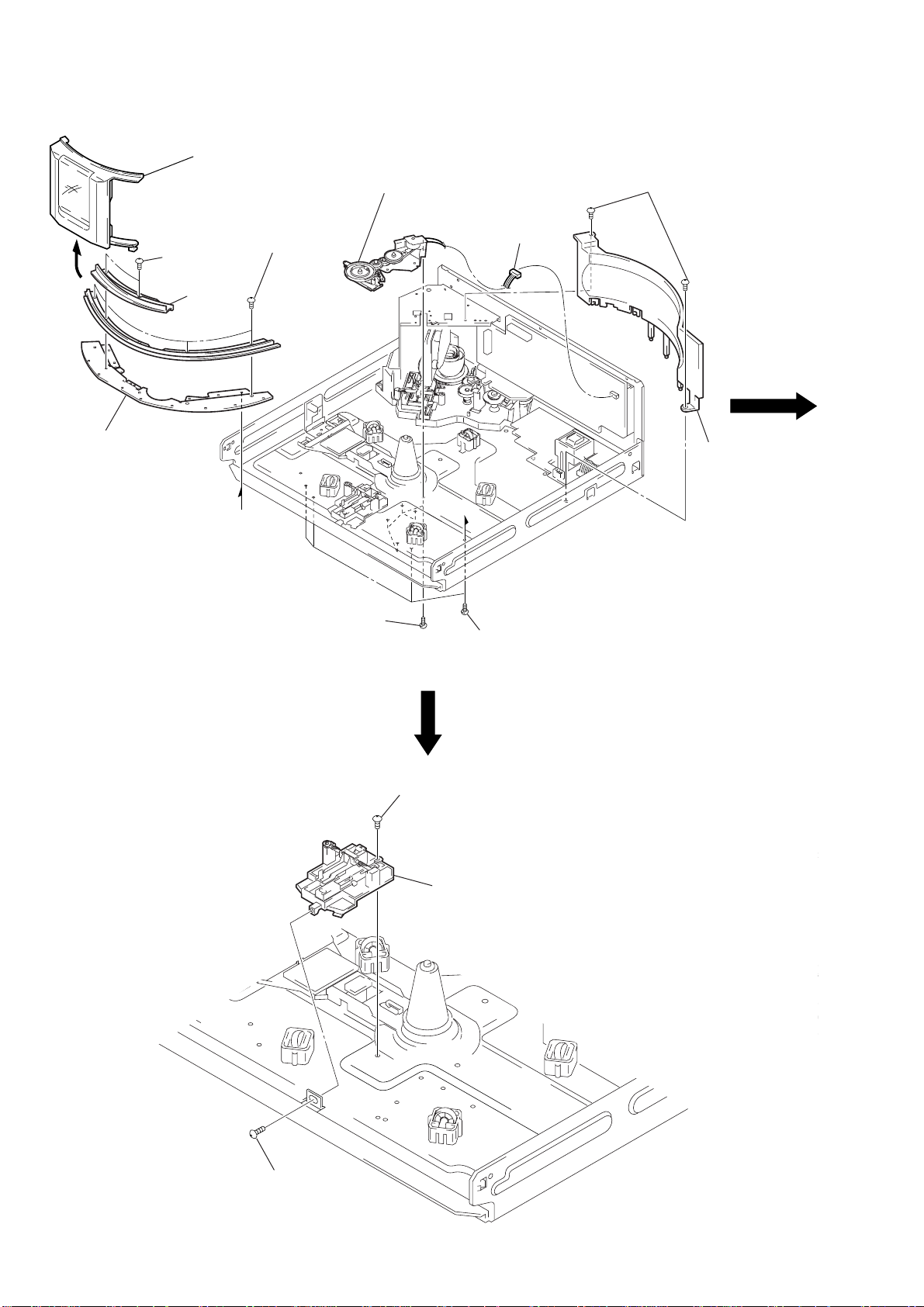
DISASSEMBLY
Note: Follow the disassembly procedure in the numerical order given.
FRONT PANEL ASSEMBLY
3
three screws
(BVTP3
×
8)
4
claw
2
connector
(CNP203)
1
flat wire
(CN502)
5
front panel
assembly
6
cover
(chassis)
TABLE (300) ASSEMBLY
4
screw
(BVTP3
5
window
6
LED board
×
8)
3
three screws
(BVTP3
7
screw
(BVTP3
4
claw
×
8)
×
16)
2
screw
×
8)
bracket (F.W)
×
8)
9
table (300)
assembly
LED board
1
connecto
(CN504)
2
two screws
(BVTP3
(BVTP3
3
8
guide (door.T)
!º
washe
9
BASE (DOOR, GEAR) ASSEMBLY AND COVER (P. T.)
r
4
Remove the
door assembly
B
9
bracket
(guide.B)
2
two screws
(BVTP3
3
in arrow B
direction.
7
three screws
(BVTP3
×
8)
cover
(front)
×
8)
6
base (door.gear)
assembly
1
connector
(CN509)
!º
two screws
(BVTP3
!¡
×
8)
cove
(P.T)
POP-UP ASSEMBLY
A
5
five screws
(BVTP3
A
×
8)
1
step screw
8
four screws
(BVTP3
3
pop-up assembly
×
8)
10
2
screw
(PTPWH3
×
6)
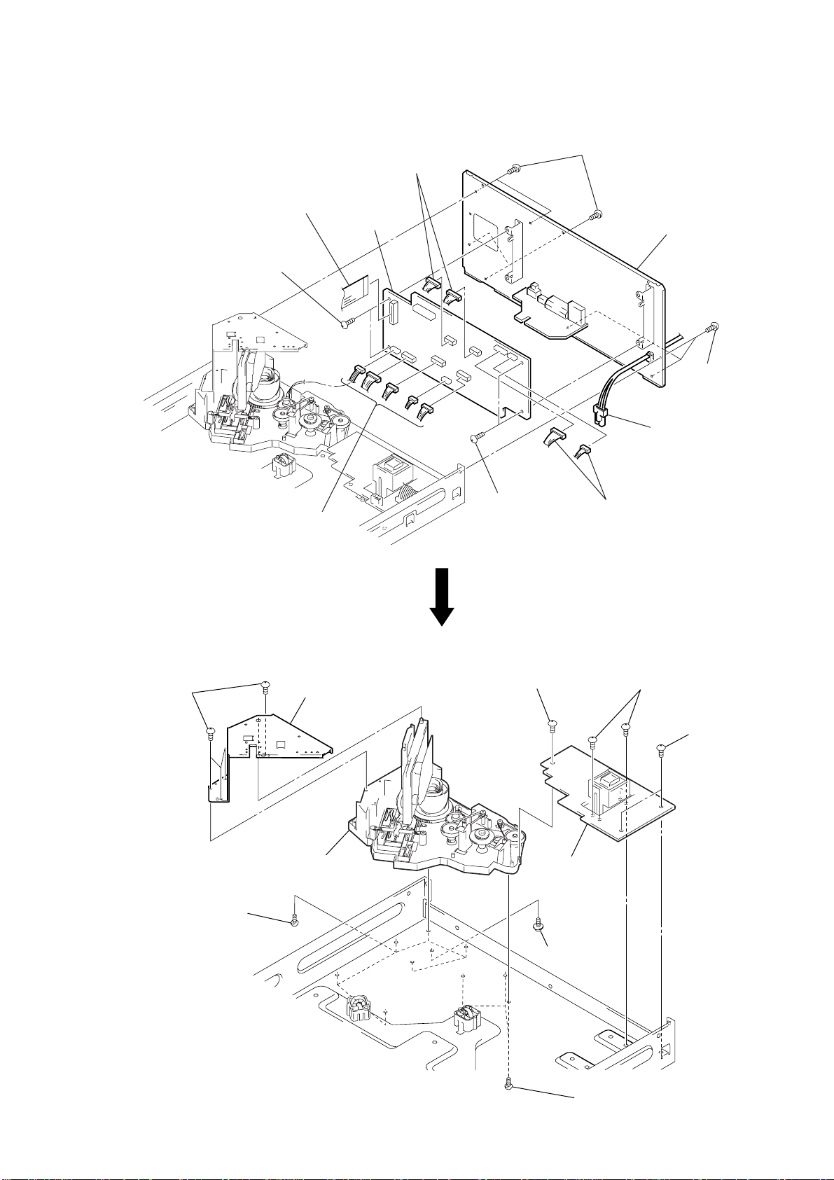
MAIN BOARD AND BACK PANEL SECTION
2
two connectors
(CN503, 507)
1
flat wire
(CN501)
4
MAIN board
3
two screws
(BVTP3
×
8)
2
five connectors
CN505, 508, 510,
()
511, 902
3
two screws
(BVTP3
6
four screws
(3
×
8)
7
back panel
section
6
three screws
(3
×
8)
5
connector
(CN991)
2
×
8)
two connectors
(CN901, 903)
POWER BOARD AND CDM ASSEMBLY
4
four screws
(BVTP3
×
8)
6
six screws
(BVTP3
5
bracket
(top)
8
CDM assembly
×
8)
1
two screws
(BVTP3
×
8)
3
POWER board
7
screw
(PSW3
2
four screws
(PTTWH3
×
8)
×
6)
1
two screws
(BVTP3
×
8)
6
three screws
(BVTP3
×
8)
11
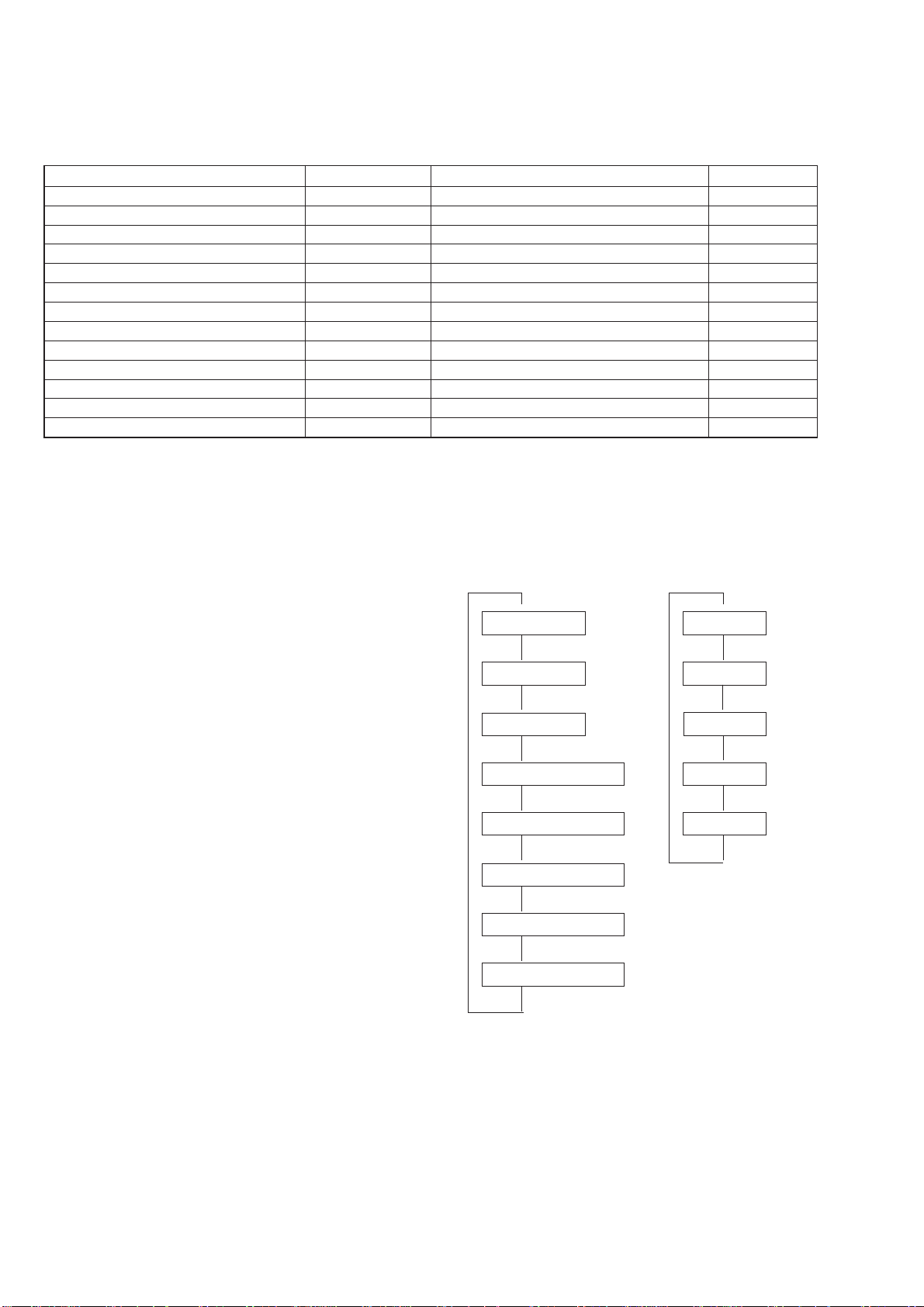
SPECIAL FUNCTION
This unit is provided with several service modes.
Details are shown in the following table.
SECTION 4
SERVICE MODE
Mode name
ALL ERASE
AGING MODE
LOARDING AGING MODE
T ABLE AGING MODE
DOOR POP UP AGING MODE
TABLE LOTATION MODE
TITLE MEMO SHIFT MODE
MODEL NAME DISPLAY
MICROPROCESSOR VERSION DISPLAY
ALL LIT MODE
MECHANISM ADJUSTMENT MODE
SHIPMENT MODE
TITLE MEMO RECORDING CHECK MODE
Note 1
Do not execute unless with a proper reason, otherwise the memory of the title memo recorded by the customer will be erased.
The title memo recording check mode is not required for servicing. Do not execute.
Power supply state
OFF
ON
ON
ON
ON
ON
ON
ON
ON
ON
ON
ON
ON
Button operation
[CLEAR] + []
[GROUP1] + [OPEN/CLOSE] + [+100]
[GROUP2] + [OPEN/CLOSE] + [+100]
[GROUP3] + [OPEN/CLOSE] + [+100]
[GROUP4] + [OPEN/CLOSE] + [+100]
[GROUP5] + [OPEN/CLOSE] + [+100]
[GROUP7] + [OPEN/CLOSE] + [+100]
[GROUP1] + [] + [+100]
[GROUP2] + [] + [+100]
[GROUP3] + [] + [+100]
[GROUP4] + [] + [+100]
[GROUP5] + [] + [+100]
[GROUP6]
1/u
§
§
§
§
§
§
·
·
·
·
·
+ [] + [+100]
·
ALL ERASE
This mode is used for clearing information such as the title memo.
Do not execute if information such as the title memo is not to be
erased.
Procedure:
While pressing the [CLEAR] button with the power OFF, press
the 1/u button and turn on the power.
[]
The fluorescent indicator tube displays “ALL ERASE” and all
memories will be cleared.
AGING MODE
• Mode which repeatedly changes and plays back discs automatically in the unit.
• It will repeat aging as long as no errors occur.
• If an error occurs during aging, it will stop all servos, motors,
etc. instantaneously, display the error number, and stop operations. However, the stopping conditions differ according to
whether the unit is equipped with the “self-protection function
during errors” described later.
The function serves to maintain the state of the unit when errors
occur.
Sequence of Aging Mode
$
1. Disc change
$
2. Load in
$
3. TOC read
$
4. Access of last track
$
5. 3 second playback
$
6. Access of first track
Order of Disc Change
Remarks
Note 1
Used in adjustment
Note 1
Note 1
$
1. No. 60
$
2. No. 240
$
3. No. 180
$
4. No. 300
$
5. No. 120
$
12
$
7. 3 second playback
$
8. Load out
$
Special Aging Mode Functions
e
The aging mode is provided with the following convenient functions
• Disc setting mode (*1)
• Selection of presence of protection function during error (*2)
• Count function of aging cycle (*3)
*1 Disc setting mode:
5 discs are set before setting the aging mode. This mode makes
the setting of these discs more easy.
*2 Self protection function during errors:
Function which voluntarily corrects errors which occur during normal operations by retries.
If this function is not provided, all operations will be stopped
without retiring. It is suitable for checking errors with low reproducibility .
If this function is provided, and errors can be corrected by
retries, aging will be continued without stopping.
*3 Aging cycle count function:
Functions which displays the number of agings carried out on
the Fluorescent indicator tube in numbers. One aging cycle
consists of five discs.
number of disc tabl
1DISC
CD1
120
Aging Procedure
1. Turn ON the power of the unit. Press the [OPEN/CLOSE]
§
and open the front cover.
2. Change the [COMMANDMODE] switch (S901) on set to [CD1].
3. Press the [AGINGSTART] button of the remote commander
for aging mode (J-2501-123-A).
4. When the disc set mode is set, the [] and [] LEDs blink.
·
P
5. Rotate the [DISC/CHARACTER] dial. The slits (No. 60, 120,
180, 240, 300) for setting the discs will come forward. Insert
the discs into these slits. Do not set the discs in other slits.
6. Set whether the self-protection function during errors is
equipped with the unit. Press the [REPEAT] button. If “RE-
PEA T” is displayed on the fluorescent indicator tube, it means
the function is provided. If “REPEAT” is not displayed, it
means the function is not provided.
Error Display
Disc number
when aging
180
120 E01 #
Disc number
with error
Error code
Aging cycle
number
AGED 10
7. Press the · button.
8. The · LED blinks, the aging mode is set, and aging is
started.
number of agings
9. If errors occur during aging, the error number will be displayed
on the fluorescent indicator tube. (Refer to the following table
for the details of the errors.)
10. Aging will be repeated as long as no errors occur.
11. After each aging cycle, the number displayed on the fluorescent indicator tube will increase.
12. To release this mode, press the 1/
Note: As an alternative to steps 2 and 3, press the [GROUP1] button,
[OPEN/CLOSE] button, and [+100] button at the same time.
§
Error code
Code number
Err 01
Err 02
Err 03
Err 04
Err 05
Err 06
Err *1
Err *2
Err *3
Err *4
Err *5
Err *6
Err *7
DISC sensor check 1
DISC sensor check 2
Table operation check 1
Table operation check 2
Loading operation check 1
Loading operation check 2
BU related check 1
BU related check 2
BU related check 3
BU related check 4
BU related check 5
BU related check 6
BU related check 7
Name
No disc in the specified slit
Disc in other slits
Table motor current over
No table sensor input
Load in timeover
Load out timeover
Access timeover
High speed search NG
Q data read error
BU operation (from focus search to until signal can be read) timeover
GFS monitor error
Focus cannot be imposed by focus search
Auto focus bias adjustment cannot be performed
The * numbers mean the following according to the state of the unit during aging
2 : From chucking to end of TOC read
3 : From end of TOC read to end of last track playback
4 : From end of last track playback to end of first track playback
[]
[]
Contents
[]
u button.
13
LOADING AGING MODE
• This mode is used for repeating loading operations continuously.
• Aging will be performed continuously unless an error occurs.
• When an error occurs, the error code will be displayed on the
fluorescent indicator tube.
Procedure:
1. Set a disc in the DISC 1 slit.
2. With the power ON, while pressing the [GROUP2] button
§
and [OPEN/CLOSE] button, press the [+100] button.
3. When the mode is set, both the [] and [] indicators will
·
P
start to blink.
4. When the [] button is pressed, only the [] indicator will
·
·
blink and aging starts.
1/
5. To release the mode, press the [] button.
u
The error codes displayed during operations and when errors occur are the same as the “AGING MODE” described earlier.
TABLE AGING MODE
• This mode is used for rotating the table randomly.
• Aging will be performed continuously unless an error occurs.
• When an error occurs, the error code will be displayed on the
fluorescent indicator tube.
Procedure:
1. Set discs in slits 1, 2, 99, 100, and 200.
2. With the power ON, while pressing the [GROUP3] button
§
and [OPEN/CLOSE] button, press the [+100] button.
3. When the mode is set, both the [] and [] indicators will
·
P
start to blink.
4. When the [] button is pressed, only the [] indicator will
·
·
blink and aging starts.
1/
u
5. To release the mode, press the
[] button.
During aging, operations will be carried out sequentially in the
order of No. 1, No. 2, No. 100, No. 99, and No. 200 slits.
The error codes displayed during operations and when errors occur are the same as the “AGING MODE” described earlier.
DOOR POP UP AGING MODE
• This mode is used for performing aging of the CD pop up part
and door open/close.
It is used for checking if operations are performed normally.
Procedure:
1. To select a slot to be aged, press the [OPEN/CLOSE] button
§
and rotate the [DISC/CHARACTER] knob with the front door
opened to select a number.
2. With the power ON, while pressing the [GROUP4] button
§
and [OPEN/CLOSE] button, press the [+100] button.
3. When the [] button is pressed, aging starts, and door open/
·
close and up/down operations of the pop up part are performed
continuously.
4. To release the mode, press the [] button.
u
1/
The number of times aging is performed will be displayed on the
fluorescent indicator tube during operations.
TABLE ROTATION MODE
• This mode is used for electrical adjustments. Refer to the section on Electrical Adjustments.
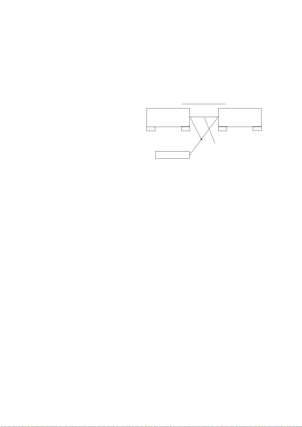
TITLE MEMO SHIFT MODE
• This mode is used for writing title memo information recorded
in this unit in a different unit.
Use it for transferring disc memo contents written by the customer to the new units when replacing the unit, etc.
Connection:
Flow of data
This unit
(Copy source)
COMMAND MODE: CD3 COMMAND MODE: CD1
CONTROL A1 II
$
$
CONTROL A1 II connection cord
provided
$
Another unit
$
(Copy destination)
Procedure:
1. Connect two units using the [CONTROLA1II] connection cord
shown in the figure.
2. Set the [COMMANDMODE] switch of the copy source unit
to [CD3] and the [COMMANDMODE] switch of the copy des-
tination unit to [CD1].
3. With the power on, while pressing the [GROUP7] button and
§
[OPEN/CLOSE] button of the copy destination unit, press
[+100] button.
the
4. When the data has been transferred, the fluorescent indicator
tube displays “complete” for about 1 second.
MODEL NAME DISPLAY
• Model names can be displayed on the fluorescent indicator tube
for checking the microprocessor model setting, etc.
Procedure:
With the power ON, while pressing the [GROUP1] and []
·
buttons, press the [+100] button.
The model name is displayed on the fluorescent indicator tube.
MICROPROCESSOR VERSION DISPLAY
• The microprocessor version can be displayed on the fluorescent
indicator tube.
Procedure:
With the power ON, while pressing the [GROUP2] and []
·
buttons, press the [+100] button.
The microprocessor version is displayed on the fluorescent indicator tube.
ALL LIT MODE
• This mode is used for lighting the whole fluorescent indicator
tubes and LEDs.
Procedure:
With the power ON, while pressing the [GROUP3] and []
·
buttons, press the [+100] button.
Both the fluorescent indicator tubes and LEDs will light up completely.
To release this mode, press the [] mode.
u
1/
14

MECHANISM ADJUSTMENT MODE
• This mode is used for mechanism adjustments. Refer to the section on Mechanism Adjustments.
SHIPMENT MODE
• This mode is used for setting the unit to the shipment state.
Do not execute it without a proper reason as it erases the memory
of the title memo recorded by the customer.
Procedure:
[COMMANDMODE] switch to [CD1] and the [TIMER]
Set the
switch to [OFF]. Next, with the power ON, while pressing the
[GROUP5] button and [] button, press the [+100] button. If
the switch state is normal, the model name will be displayed on
the fluorescent indicator tube and the unit will set into the shipment mode.
If the various switches are not set to their designated positions,
error codes will be displayed on the fluorescent indicator tube.
TITLE MEMO RECORDING CHECK MODE
This mode is not required for servicing. Do not execute without a
proper reason.
If executed, the memory of the title memo recorded by the customer will be erased.
·
15
SECTION 5
TEST MODE
5-1. ADJ MODE
1. Turn ON the power of the unit, set disc to disc table, and perform chucking.
2. Remove the power cord from the outlet.
3. To set ADJ mode, connect the ^¡ pin of IC501 (ADJ) of the
MAIN board to ground, and connect the power cord to the
outlet.
In this mode, table rotation and loading operations are not performed because it is taken that the disc has already been chucked.
Note: The same operations are also performed in the following when the
^¡ pin of IC501 (ADJ) is connected to ground after turning on the
power.
• Direct search (movement of sledding motor) is not performed
during accessing
• Ignored even when GFS becomes L
• Ignored even when the Q data cannot be read
• Focus gain does not decrease
ADJ Mode Special Functions Table
Button
CONTINUE
SHUFFLE
PROGRAM
GROUP 3 (3)
GROUP 8 (8)
CHECK
Servo average display
Displays VC, FE, RF, TE and traverse in hexadecimal numbers
Focus bias display
Each time this is pressed, the focus bias is
switched between 1 and 2
(1)
Bias actually set Optimum bias Minimum jitter
(2)
U:Upper aliasing bias L:Lower aliasing bias
Auto gain display
Displays focus, tracking, sledding in
hexadecimal numbers
Turns off the tracking and sledding servo
Turns on the tracking and sledding servo
S-curve observation mode.
(Release this mode when the 1/u button is pressed.)
Function
[]
5-2. KEY AND DISPLAY CHECK MODE
To set this mode, connect the ^º pin of IC501 (AFADJ) on the
MAIN board to ground, and connect the power cord to the outlet.
Note: When this mode is executed, all title memos recorded will be erased.
• When this button is pressed, “line # No. #” will be displayed. However,
these will not be displayed for the following special buttons. However,
these will not be displayed for the following special buttons.
[]
p (stop) button : FL segment check
(Refer to FL Tube Check Patterns)
[]
P (pause) button: FL grid check
(Refer to FL Tube Check Patterns)
[]
The P LED also lights up simultaneously.
[]
· (play) button : All FL segment and grid will light up.
[]
· LED also lights up simultaneously.
TIMER switch : When the switch position is[PLAY], the
[STANDBY] LED lights up. It goes OFF
when set to[OFF].
Each time this button is pressed, the value of the “Go+ ## keys”
increases. Buttons pressed once will not be counted when pressed
again.
FL Tube Check Patterns
Segment check
Magnified
Grid check
A B C D E F G
• Checking Location
– MAIN BOARD (Conductor Side) –
R516
^º
pin (ADJ)
^¡
pin (AFADJ)
R517
75
76
GND
51
IC501
100 1
50
• When the jog dial is rotated to the right, the GROUP LEDs light
up in the order of 1n2..8nHIT LISTnEASY PLA YnMEGA
CONTROLn1.
• When the jog dial is rotated to the left, the GROUP LEDs light
up in the order of 8n 7..1n MEGA CONTROLn EASY
PLAYnHIT LISTn8.
• Abbreviation
FL: Fluorescent Indicator Tube
26
25
16
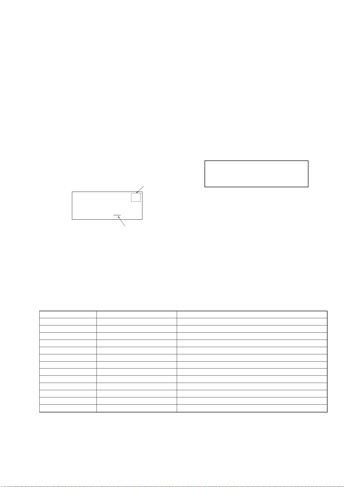
SECTION 6
GROUP 1
GROUP 2
GROUP 4
Lever (pop up)
Fix to the center so that the
lever (POP UP) does not
touch the slit.
Cover (chassis)
At this position,this
part will be locked.
MECHANICAL ADJUSTMENTS
POP UP MECHANISM ADJUSTMENT
1. With the power ON, while pressing the [GROUP4] and []
buttons, press the [+100] button to enter the mechanism adjustment mode.
2. Press the [GROUP1] button to operate the loading mechanism, and continue pressing until the disc table locks. (Fig-1)
3. Press the [GROUP2] button to raise the pop up part.
4. Remove the cover (chassis), loosen the adjusting screw, move
the screwdriver left and right until the lever (POP UP) does
not touch the slit wall, and secure the screw. (Fig-2)
The following buttons have special functions in this mode.
[GROUP1] button: Loading mechanism IN operation
[GROUP5] button: Loading mechanism OUT operation
[GROUP2] button: Pop up part UP operation
[GROUP6] button: Pop up part DOWN operation
·
Fig-1
Fig-2
17
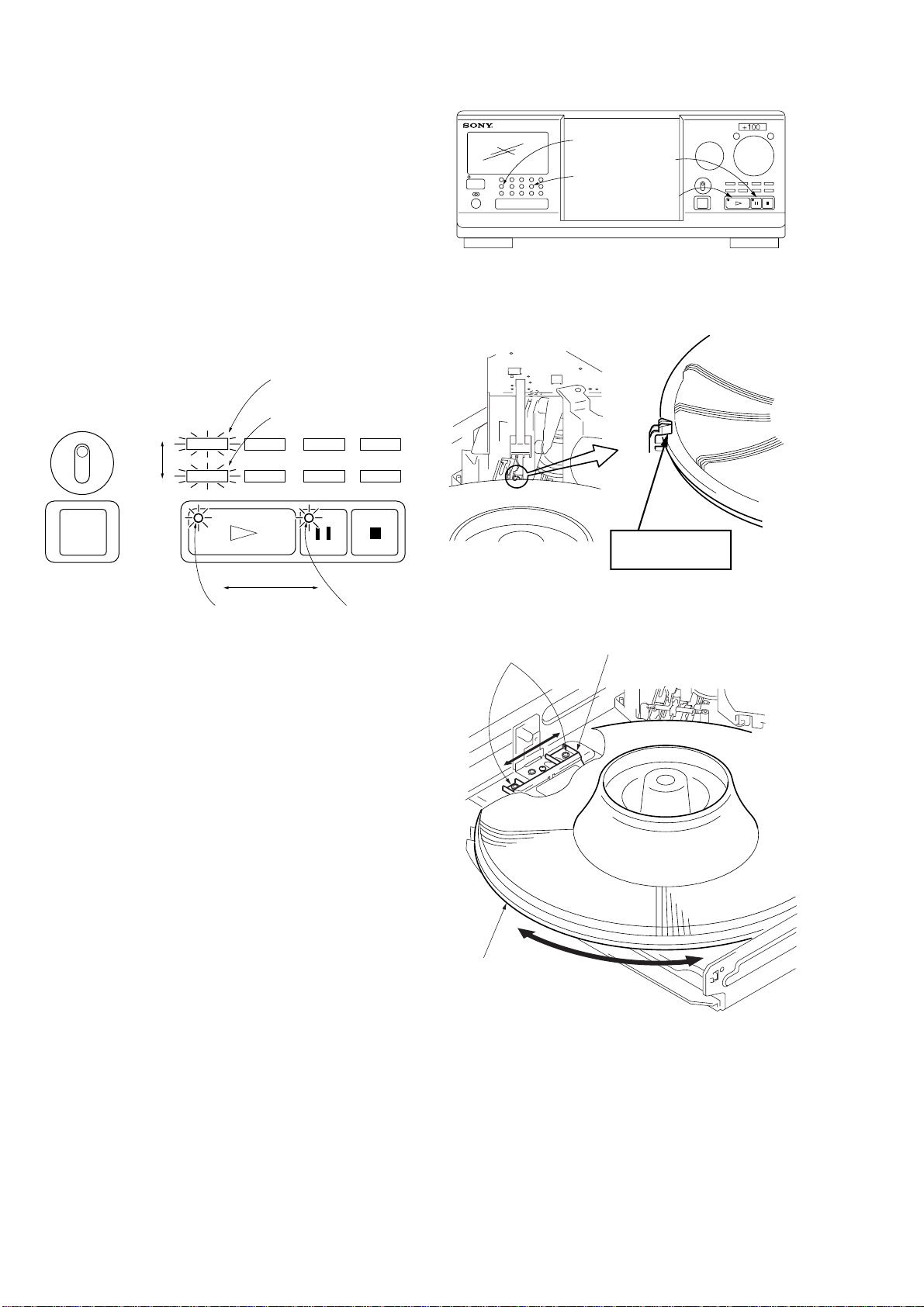
SENSOR ADJUSTMENT
1. With the power ON, while pressing the [GROUP4] and []
·
buttons, press the [+100] button to enter the mechanism adjustment mode.
2. Press the [GROUP1] button to operate the loading mechanism, and continue pressing until the disc table locks. (Fig-3)
3. Loosen the fixing screw, mo v e the holder (TABLE SENSOR)
slightly, and when the LED (green) of the [] button switches
to the LED (orange) of the [] button (or vice versa), secure
P
·
the holder (TABLE SENSOR). (Fig-4)
4. Moving the disc table right and left with a hand after the screw
is fixed, the table will move by the play of a disc table. If the
LEDs light up alternately, the adjustment will be performed
correctly. (Fig-4)
Linked with P indicator
GROUP 1
PAUSE button
GROUP 4
PLAY button
PLAY indicator
Linked with
·
indicator
PAUSE indicator
Fixed screws
At this position,this
part will be locked.
Fig-3
Holder (table sensor)
18
Table assembly
Swing
Fig-4
SECTION 7
e
e
V
oscilloscope
BD board
TP (TE)
TP (VC)
ELECTRICAL ADJUSTMENT
1. CD Block is basically designed to operate without adjustment.
Therefore, check each item in order given.
2. Use YEDS-18 disc (3-702-101-01) unless otherwise indicated.
3. Use an oscilloscope with more than 10 MΩ impedance.
4. Clean the object lens by an applicator with neutral detergent
when the signal level is low than specified value with the following checks.
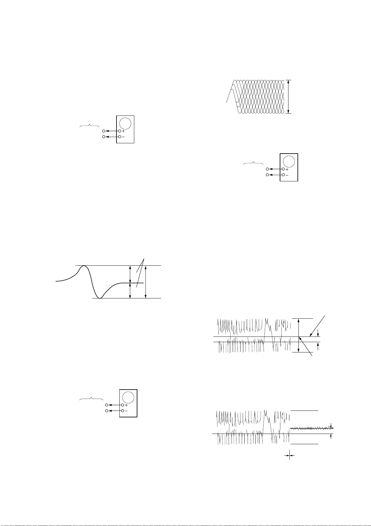
S-Curve Check
oscilloscop
BD board
TP (FE1)
TP (VC)
Procedure :
1. Chuck the disc (YEDS-18) beforehand, and remove the power
cord from the outlet.
2. Connect oscilloscope to test point TP (FE1) on BD board.
3. Connect ^¡ pin of IC501 (ADJ) on MAIN board to ground
with lead wire.
4. The ADJ mode is set when the power cord is inserted into the
outlet and power is supplied.
5. The fifth track is played automatically.
6. Press the [CHECK] button.
7. Check the oscilloscope waveform (S-curve) is symmetrical
between A and B. And confirm peak to peak level within
3±1 Vp-p.
S-curve waveform
symmetry
A
Within 3 ± 1 Vp-p
B
8. Pressing the 1/u button stops the output of the waveform
[]
(s curve).
9. After check, disconnect the lead wire connected in step 3.
Note : • Try to measure several times to make sure than the ratio of A :
B or B : A is more than 10 : 7.
• Take sweep time as long as possible and light up the brightness
to obtain best waveform.
Note: A clear RF signal waveform means that the shape “≈” can be clearly
distinguished at the center of the waveform.
RF signal waveform
VOLT/DIV: 200 m
TIME/DIV: 500 ns
level: 1.2 Vp-p
+0.25
–0.20
Adjustment Location: BD board
E-F Balance Check
Procedure :
1. Chuck the disc (YEDS-18) beforehand, and disconnect the
power cord from the outlet.
2. Connect oscilloscpe to test point TP (TE) on BD board.
3. Connect ^¡ pin of IC501 (ADJ) on MAIN board to ground
with lead wire.
4. The ADJ mode is set when the power cord is inserted into the
outlet and power is supplied.
5. The fifth track is played automatically.
6. Press the [GROUP3] button. (The tracking servo and the sledding servo are turned OFF.)
7. Check the level B of the oscilliscopes waveform and the A
(DC voltage) of the center of the Traverse waveform.
Confirm the following :
A/B x 100 = less than ± 22%
Traverse waveform
Center of the waveform
B
0V
A (DC voltage)
Adjustment Location: BD board
RF Level Check
oscilloscop
BD board
TP (RFO)
TP (VC)
Procedure :
1. Connect oscilloscope to test point TP (RFO) on BD board.
2. Turn Power ON.
3. Put disc (YEDS-18) in to play the number five track.
4. Confirm that oscilloscope waveform is clear and check RF
signal level is correct or not.
±
level : 1.3
0.6 mVp-p
8. Press the [GROUP8] button. (The tracking servo and sledding servo are turned ON.) Confirm the C (DC voltage) is almost equal to the A (DC voltage) is step 7.
Traverse waveform
0V
Tracking servo
Sledding servo
OFF
Tracking servo
Sledding servo
ON
C (DC
voltage)
9. Disconnect the lead wire connected in step 3.
Adjustment Location: MAIN board
19
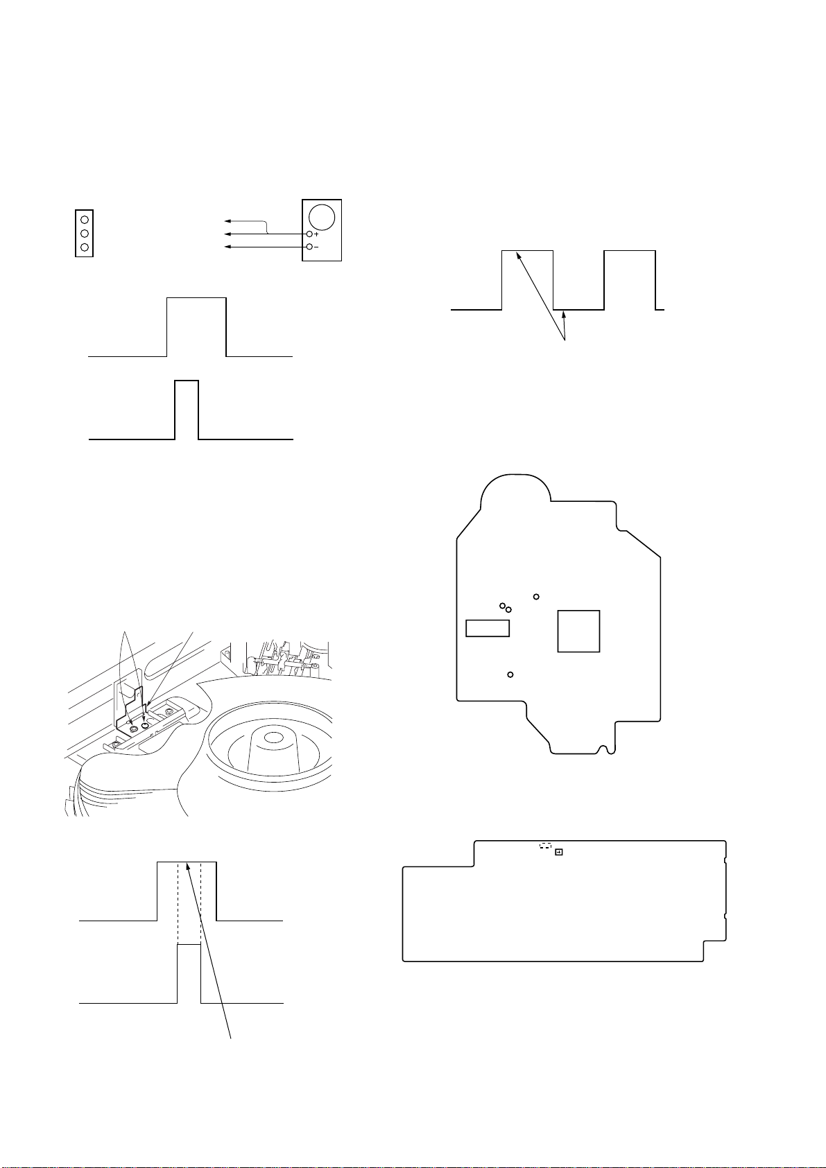
Disc In Detect Sensor Adjustment
D.S
Adjust so that these widths
become the same.
Be sure to perform this adjustment after sensor adjustment in
MECHANICAL ADJUSTMENT .
Connection:
MAIN board
CN506
T.P
GND
D.S
T.P: Pin
D.S: Pin
GND: Pin
1
3
2
oscilloscope
W aveform:
D.S
5. Rotate the [DISC/CHARACTER] knob in the counterclockwise direction and the disc table starts to rotate in the same
direction. Check that the waveform at this time is the same as
that in step 4. If larger by a considerable extent, rotate the
[DISC/CHARACTER] knob in the clockwise direction and the
disc table starts to rotate in the same direction. Repeat from
step 4.
6. Rotate RV501 of the MAIN board and adjust so that the H and
L portions of the D.S waveform become the same.
Adjustment Location: MAIN board
P.T
1. Connect the oscilloscope to Pins 1, 2, and 3 of CN506 of
the MAIN board.
2. Check that no discs are loaded in the unit.
3. With the power ON, while pressing the [GROUP5] and
§
[OPEN/CLOSE] buttons, press the [+100] button. The disc
table starts to rotate in the clockwise direction.
4. Loosen the fixing screw , move the mounting board (SENSOR),
and secure the mounting board (SENSOR) at the point the H
portion of the P.T waveform comes the center of the H portion
of the D.S waveform.
Fixing screw Mounting board (SENSOR)
• Adjustment Location
– BD BOARD (Conductor Side) –
TP
TP
(VC)
(RFO)
TP
(TE)
IC101
TP
(FE1)
IC103
– MAIN BOARD (Component Side) –
CN506
3
1
RV501
20
D.S
P.T
Should be at the center
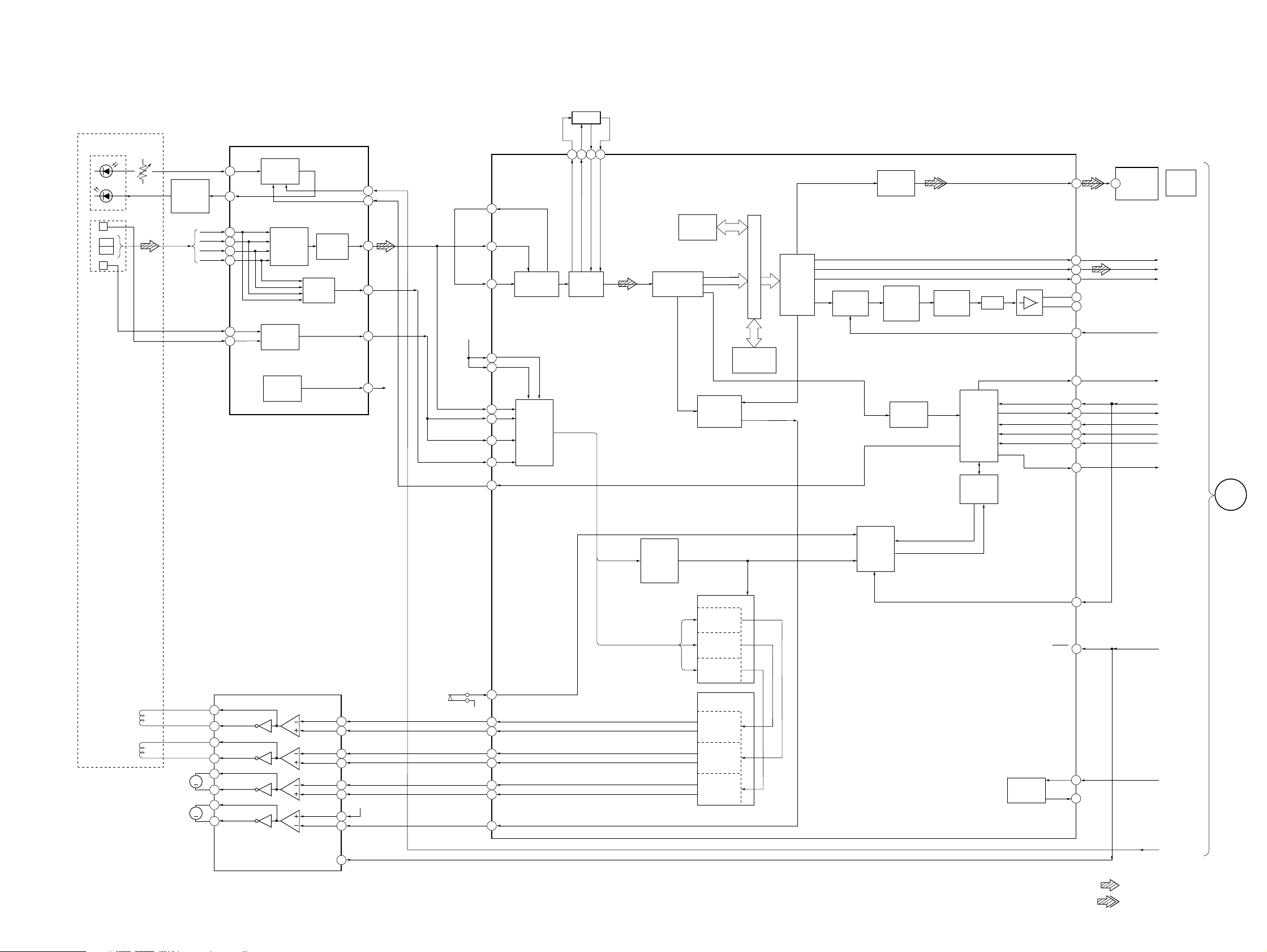
8-1. BLOCK DIAGMRAM – BD Section –
CDP-CX333ES/CX555ES
SECTION 8
DIAGRAMS
OPTICAL PICK-UP
(KSS-213B/C2N)
LASER
DIODE
PD
LD
DETECTOR
E
PD1
PD2
F
LD
POWER
AUTOMATIC
POWER
CONTROL
Q101
APC LD
AMP
SUMMING
AMP
TRACKING
ERROR
AMP
VC
BUFFER
IC103
RF
RF AMP,FOCUS/TRACKING ERROR AMP
PD
4
LD
3
A
5
B
6
C
7
D
8
F
10
E
11
FOCUS
ERROR
AMP
RF EQ
AMP
HOLDSW
LDON
RFO
FILTER
INTERNAL BUS
ERROR
CORRECTOR
IC101
D/A
INTERFACE
SERIAL
IN
INTERFACE
SERVO
INTERFACE
DIGITAL
OUT
OVER
SAMPLING
DIGITAL
FILTER
SUBCODE
PROCESSOR
3rd ORDER
NOISE
SHAPER
PWM
CPU
INTERFACE
SERVO
AUTO
SEQUENCER
DOUT
LRCK
PCMD
BCK
LOUT1
LOUT2
SYSM
SCOR
SQCK
SQSO
DATA
CLOK
SENS
60 3
61
62
63
72
75
20
XLAT
IC901
OPTICAL
TRANSCEIVER
4
2
1
5
6
7
8
DIGITAL
OPTICAL
LRCK
ADATA
BCLK
AMUTE
SCOR
SQCK
SUBQ
DATA
XLT
CLOK
SENS
OUT
A
MAIN
SECTION
(Page 22)
5654 53 55
FILI
PCO
FILO
CLTV
21
22
16
FE
14
TE
13
VC
12
VC
ASYO
48
RFAC
51
ASYI
ASYMMETRY
49
CORRECTION
VC
VC
38
CE
42
RFDC
43
TE
41
40
39
14
SE
FE
XLON
A/D
CONVERTER
DIGITAL
PLL
DIGITAL SIGNAL PROCESSOR,DIGITAL SERVO PROCESSOR,DIGITAL FILTER,D/A CONVERTER
16K
RAM
EFM
DEMODULATOR
DIGITAL
CLV
MIRR
DFCT
FOK
DETECTOR
SCLK
XRST
XTAI
XTAO
9
3
66
67
XRST
16.9MHz
AGC
SERVO DSP
FOCUS
SERVO
TRACKING
SERVO
FOCUS/TRACKING COIL DRIVE,
CH1 OUT F
TRACKING
COIL
FOCUS
COIL
M102
(SLED)
M101
(SPINDLE)
05
1
CH1 OUT R
2
CH3 OUT F
16
CH3 OUT R
17
CH2 OUT F
13
M
CH2 OUT R
12
CH4 OUT F
27
M
CH4 OUT R
26
IC102
SPINDLE/SLED MOTOR DRIVE
CH1 R IN
CH1 F IN
CH3 R IN
CH3 F IN
CH2 R IN
CH2 F IN
VB IN
VS IN
MUTE
4
5
19
20
10
9
VC
23
24
15
S101
(LIMIT IN)
D+5V
SSTP
27
TFDR
30
TRDR
31
FFDR
32
FRDR
33
SRDR
29
SFDR
28
MDP
26
SLED
SERVO
PWM
GENERATOR
TRACKING
PWM
GENERATOR
FOCUS
PWM
GENERATOR
SLED
PWM
GENERATOR
TIMING
LOGIC
• SIGNAL PATH
: CD PLAY(ANALOG OUT)
: CD PLAY(DIGITAL OUT)
2121
 Loading...