


4-109-708-31(1)
(1)
Sony Corporation Printed in Malaysia
BD/DVD Home Theatre System
Operating Instructions
BDV-IT1000/BDV-IS1000
© 2008 Sony Corporation
WARNING
Civic Office, your household waste disposal service or
the shop where you purchased the product.
To reduce the risk of fire or electric
shock, do not expose this apparatus to
rain or moisture.
Do not install the appliance in a confined space, such
as a bookcase or built-in cabinet.
To reduce the risk of fire, do not cover the ventilation
opening of the apparatus with newspapers, tablecloths,
curtains, etc. Do not place the naked flame sources
such as lighted candles on the apparatus.
To reduce the risk of fire or electric shock, do not
expose this apparatus to dripping or splashing, and do
not place objects filled with liquids, such as vases, on
the apparatus.
Do not expose batteries or apparatus with batteryinstalled to excessive heat such as sunshine, fire or the
like.
In door use only.
Caution - The use of optical instruments
with this product will increase eye
hazard.
This appliance is
classified as a CLASS 1
LASER product. This
marking is loca ted on the
rear exterior.
Disposal of waste
batteries (applicable in
the European Union and
other European
countries with separate
collection systems)
This symbol on the battery or on the packaging
indicates that the battery provided with this product
shall not be treated as household waste. By ensuring
these batteries are disposed of correctly, you will help
prevent potentially negative consequences for the
environment and human health which could otherwise
be caused by inappropriate waste handling of the
battery. The recycling of the materials will help to
conserve natural resources. In case of products that for
safety, performance or data integrity reasons require a
permanent connection with an incorporated battery,
this battery should be replaced by qualified service
staff only. To ensure that the battery will be treated
properly, hand over the product at end-of-life to the
applicable collection point for the recycling of
electrical and electronic equipment. For all other
batteries, please view the section on how to remove the
battery from the product safely. Hand the battery over
to the applicable collection point for the recycling of
waste batteries. For more detailed information about
recycling of this product or battery, please contact your
local Civic Office, your household waste disposal
service or the shop where you purchased the product.
Disposal of Old
Electrical & Electronic
Equipment (Applicable
in the European Union
and other European
countries with separate
collection systems)
This symbol on the product or
this product shall not be treated as household waste.
Instead it shall be handed over to the applicable
collection point for the recycling of electrical and
electronic equipment. By ensuring this product is
disposed of correctly, you will help prevent potential
negative consequences for the environment and human
health, which could otherwise be caused by
inappropriate waste handling of this product. The
recycling of materials will help to conserve natural
resources. For more detailed information about
recycling of this product, please contact your local
GB
2
on its packaging indicates that
Notice for customers: the following
information is only applicable to
equipment sold in countries applying EU
directives.
The manufacturer of this product is Sony Corporation,
1-7-1 Konan Minato-ku Tokyo, 108-0075 Japan. The
Authorized Representative for EMC and product
safety is Sony Deutschland GmbH, Hedelfinger
Strasse 61, 70327 Stuttgart, Germany. For any service
or guarantee matters please refer to the addresses given
in separate service or guarantee documents.
Precautions
On power sources
• The unit is not disconnected from the mains as long
as it is connected to the AC outlet, even if the unit
itself has been turned off.
• As the main plug is used to disconnect the unit from
the mains, connect the unit to an easily accessible AC
outlet. Should you notice an abnormality in the unit,

disconnect the main plug from the AC outlet
immediately.
Copyrights and Trademarks
• This product incorporates copyright protection
technology that is protected by U.S. patents and other
intellectual property rights.
Use of this copyright protection technology must be
authorized by Macrovision, and is intended for home
and other limited viewing uses only unless otherwise
authorized by Macrovision.
Reverse engineering or disassembly is prohibited.
• This system incorporates with Dolby* Digital and
Dolby Pro Logic (II) adaptive matrix surround
decoder and the DTS** Digital Surround System.
* Manufactured under license from Dolby
Laboratories.
“Dolby”, “Pro Logic”, and the double-D
symbol are trademarks of Dolby Laboratories.
** Manufactured under license under U.S. Patent
#’s: 5,451,942; 5,956,674; 5,974,380;
5,978,762; 6,226,616; 6,487,535 & other U.S.
and worldwide patents issued & pending. DTS
is a registered trademark and the DTS logos,
Symbol, DTS-HD and DTS-HD Master Audio
are trademarks of DTS, Inc. © 1996-2008 DTS,
Inc. All Rights Reserved.
• This system incorporates High-Definition
Multimedia Interface (HDMI
HDMI, the HDMI logo and High-Definition
Multimedia Interface are trademarks or registered
trademarks of HDMI Licensing LLC.
• “AVCHD” and the “AVCHD” logo are trademarks of
Matsushita Electric Industrial Co., Ltd. and Sony
Corporation.
• Java and all Java-based trademarks and logos are
trademarks or registered trademarks of Sun
Microsystems, Inc.
• “BD-Live” and “BonusView” are trademarks of Bluray Disc Association.
• “BRAVIA” is a trademark of Sony Corporation.
• “S-AIR” and its logo are trademarks of Sony
Corporation.
• , “XMB,” and “xross media bar” are trademarks of
Sony Corporation and Sony Computer Entertainment
Inc.
• “PLAYSTATION” is a trademark of Sony Computer
Entertainment Inc.
• “Blu-ray Disc” is a trademark.
• “Blu-ray Disc,” “DVD+RW,” “DVD-RW,”
“DVD+R,” “DVD-R,” “DVD VIDEO,” and “CD”
logos are trademarks.
• “x.v.Colour ” and “x.v.Colour” logo are trademarks of
Sony Corporation.
TM
) technology.
• “PhotoTV HD” and the “PhotoTV HD” logo are
trademarks of Sony Corporation.
• Other system and product names are generally
trademarks or registered trademarks of the
manufacturers. ™ and ® marks are not indicated in
this document.
GB
3

About These Operating
About the S-AIR function
Instructions
• The instructions in these Operating
Instructions describe the controls on the
remote. You can also use the controls on the
unit if they have the same or similar names as
those on the remote.
• Icons, such as , listed at the top of each
explanation indicate what kind of media can be
used with the function being explained.
For details, see “Playable Discs” (page 140).
• In this manual, “disc” is used as a general
reference for the BDs, DVDs, or CDs unless
otherwise specified by the text or illustrations.
• The instructions in this manual are for BDVIT1000 and BDV-IS1000. BDV-IT1000 is the
model used for illustration purposes. Any
difference in operation is clearly indicated in
the text, for example, “BDV-IT1000.”
• The Control Menu items may vary depending
on the area.
• The default setting is underlined.
The system is compatible with the S-AIR
function, which allows transmission of sound
between S-AIR products wirelessly.
The following S-AIR products can be used with
the system:
• Surround amplifier (supplied): You can enjoy
surround speaker sound wirelessly.
• Surround back amplifier (optional): You can
enjoy surround back speaker sound wirelessly.
• S-AIR receiver (optional): You can enjoy
system sound in another room.
The S-AIR product can be purchased as an
option (the S-AIR product lineup differs
depending on the area).
Notes or instructions for the surround amplifier
or S-AIR receiver in these operating instructions
refer only to when the surround amplifier or
S-AIR receiver is used.
For details on the S-AIR function, see “Using an
S-AIR Product” (page 99).
GB
4

Table of Contents
About These Operating Instructions .......4
About the S-AIR function.......................4
Index to Parts and Control ......................6
Getting Started
Step 1: Assembling the
Speakers.................................. 18
Step 2: Positioning the System... 37
Step 3: Connecting the System... 52
Step 4: Setting up the Wireless
System ..................................... 67
Step 5: Performing the Easy
Setup........................................ 69
Step 6: Enjoying Sound by Each
Function................................... 73
Playback
Playing a BD/DVD ............................... 74
Playing a CD.........................................82
Playing Photo Files............................... 84
Sound Adjustment
Enjoying Surround Sound.....................86
Selecting the Sound Mode ....................89
Changing the Sound ..............................90
Tuner
Listening to the Radio...........................92
Using the Radio Data System (RDS)....97
External Audio Device
Using the DIGITAL MEDIA PORT
Adapter ...........................................98
Using an S-AIR Product .......................99
Other Operations
Using the Control for HDMI Function for
“BRAVIA” Sync ..........................105
Calibrating the Appropriate Settings
Automatically ...............................108
Setting the Speakers............................110
Controlling the TV or Other Components
with the Supplied Remote.............111
Using the Sound Effect .......................115
Using the Sleep Timer ........................116
Deactivating the Buttons on the Unit..116
Settings and Adjustments
Using the Setup Display ..................... 117
[Network Update]............................... 118
[Video Settings].................................. 119
[Audio Settings].................................. 121
[BD/DVD Viewing Settings].............. 122
[Photo Settings] .................................. 124
[HDMI Settings]................................. 124
[System Settings]................................ 126
[Network Settings].............................. 127
[Easy Setup]........................................ 128
[Resetting] .......................................... 129
Additional Information
Precautions.......................................... 130
Notes about the Discs ......................... 131
Troubleshooting.................................. 132
Self-diagnosis Function ...................... 139
Playable Discs..................................... 140
Supported Audio Formats................... 143
Video Output Resolution .................... 144
Specifications...................................... 146
Language Code List............................ 149
Terms and Conditions of Use and End
User License Agreement .............. 150
Glossary.............................................. 153
Index ................................................... 156
GB
5
Index to Parts and Control
For more information, refer to the pages
indicated in parentheses.
• : For system operations
• : For TV operations
• : For set-top box/digital satellite
receiver/Sony component (such as VCR, or
DVD player/recorder, etc.) operations
(For details, see “Controlling the TV or Other
Components with the Supplied Remote”
(page 111).)
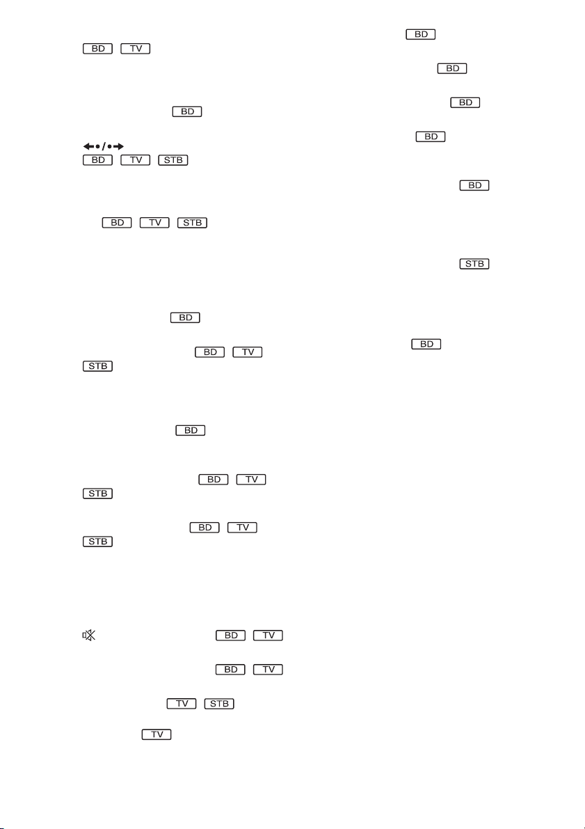
Remote control
For details of using the remote, see “Using the
remote” (page 16).
ONE-TOUCH
PLAY
BRAVIA Sync
STB TV BD
OPERATION CHANGE
CLEAR
DIGITALANALOG
SCENE
TONE NIGHT DISPLAY
U
N
E
M
P
O
T
E
T
U
R
N
H
REPLAY PRESETADVANCEPRESET
SLEEP
A/V
DECODING
SYNC
MODE
AV
0
O
E
M
TUNER
MENU
DVD RECORDER
HDD DVD
P
SOUND MODEFUNCTION
PROG
O
321
654
987
TIME
P
U
DIRECT
TUNING
DISPLAY
/ENTER
P
/
M
E
N
P
O
TUNING
1
2
3
4
5
6
U
7
S
N
O
S
I
L
T
O
O
T
8
9
0
qa
THEATRE
SEARCH
R
TUNING
S-AIR MODE
With the cover opened.
Number 5, ANALOG/ , PROG +, and H
buttons have a tactile dot. Use the tactile dot as
a reference when operating.
A THEATRE (106)
Switches to the optimum video mode for
watching movies automatically.
ONE-TOUCH PLAY (74, 106)
By only pressing the button, the TV turns
on, the TV is set for BD/DVD input
selector, and the system starts playing a disc
automatically.
AV "/1 (on/standby) (111)
Turns on the connected component such as
the TV or set-top box/digital satellite
receiver, or set to standby mode.
"/1 (on/standby) (69, 74, 92)
Turns on the system, or set to standby
mode.
B A (open/close) (74)
Opens or closes the disc tray.
OPERATION CHANGE (16, 111)
Changes the source to be operated on the
remote.
: You can operate set-top box/digital
satellite receiver.
: You can operate TV.
: You can operate the unit.
C Number buttons (74, 93, 111)
Enters the title/chapter numbers or radio
frequencies, etc.
CLEAR (79, 111)
Clears the entry field.
/ (text) (114)
Accesses text.
TIME (80)
Displays the elapsed/remaining playback
time in the front panel display.
GB
6
ENTER (111)
Enters the selected item.
(114)
-
- is for selecting a channel number greater
than 10.
D (audio) (90)
Selects the audio format/track.
(subtitle) (77)
Selects the subtitle language when multilingual subtitles are recorded on a BDROM/DVD VIDEO.
(angle) (77)
Switches to other viewing angles when
multi-angles are recorded on a BD-ROM/
DVD VIDEO.
t/ (TV input) (111)
Switches the TV’s input source between the
TV and other input sources.
ANALOG (111)
Switches to analogue mode.
DIGITAL (111)
Switches to digital mode.
(wide) (111)
Changes the aspect ratio of the connected
TV.
E SCENE SEARCH (79)
Switches to Scene Search mode that lets
you move quickly between scenes within
the title currently being played back.
TONE (115)
Adjusts the sound by changing the
frequency envelope of a sound.
NIGHT (115)
Activates the night mode function.
DISPLAY (80)
Displays the playback information on the
TV screen.
F Color buttons (red/green/yellow/blue)
(94, 127)
Short cut keys for selecting items on some
BD’s menus (can also be used for BD’s
Java interactive operations).
G TOP MENU (78)
Opens or closes the BD’s or DVD’s Top
Menu.
POP UP/MENU (78)
Opens or closes the BD-ROM’s Pop-up
Menu, or the DVD’s menu.
/ (info./text reveal) (114)
Displays the information.
OPTIONS (74, 82, 84, 92)
Displays the options menu that can be
selected appears on the TV screen.
HOME (69, 74, 82, 84, 92, 99, 108, 117)
Enters or exits the system’s home menu.
RETURN (92, 111, 127)
Returns to the previous display.
C/X/x/c (69, 74, 82, 84, 92, 99, 108, 117)
Moves the highlight to select a displayed
item.
(ENTER) (69, 74, 82, 84, 92, 99, 108,
117)
Enters the selected item.
(guide) (111)
Displays the Digital Electronic Programme
Guide (EPG).
TOOLS (111)
Displays the operation menu for the current
display.
H FUNCTION (73, 74, 82, 84, 92, 98)
Selects the playback source.
SOUND MODE (89)
Selects a suitable sound mode for movies or
music.
GB
7
I ./> (previous/next) (74, 82, 84)
Skips to the previous/next chapter, track, or
file. To go to the beginning of the previous
track, press . twice.
PRESET +/– (92)
Selects the preset radio station.
REPLAY/ADVANCE (74)
Replays the scene/briefly fast forwards the
scene.
m/M (fast reverse/fast forward) (74,
82)
Fast reverses/fast forwards the disc when
pressed during playback.
Each time you press the button, search
speed changes.
To resume normal speed, press H.
TUNING +/– (92)
Searches the radio station.
H (play) (74, 82, 84)
Starts or re-starts playback.
Plays a slideshow when a disc containing
JPEG image files is inserted.
S-AIR MODE (99)
Selects playback mode for the S-AIR
receiver.
X (pause) (74, 82, 84)
K SLEEP (116)
Sets the sleep timer.
TUNER MENU (95)
Enters the menu for the tuner settings.
DIRECT TUNING (95)
Selects the radio frequencies.
A/V SYNC (82)
Adjusts the delay between the picture and
sound.
DECODING MODE (86)
Selects the system’s pre-programmed
decoding modes that bring exciting and
powerful sound of movie theaters into your
home.
DVD RECORDER (111)
Changes the operation mode for Sony DVD
recorders.
HDD: HDD mode
DVD: DVD mode
DISPLAY (92)
Changes the radio information in the front
panel display between radio frequency and
station name.
Pauses or re-starts playback.
x (stop) (74, 82, 84)
Stops playback and remembers the stop
point (resume point).
The resume point for a title/track is the last
point you played or the last photo for a
photo folder.
J (muting) (74, 82, 111)
Turn off the sound temporarily.
2 (volume) +/– (74, 111)
Adjusts the volume.
PROG +/– (111)
Selects the channels up and down.
c/C (114)
After pressing /, you can select the next
(
c) or previous (C) text page.
GB
8
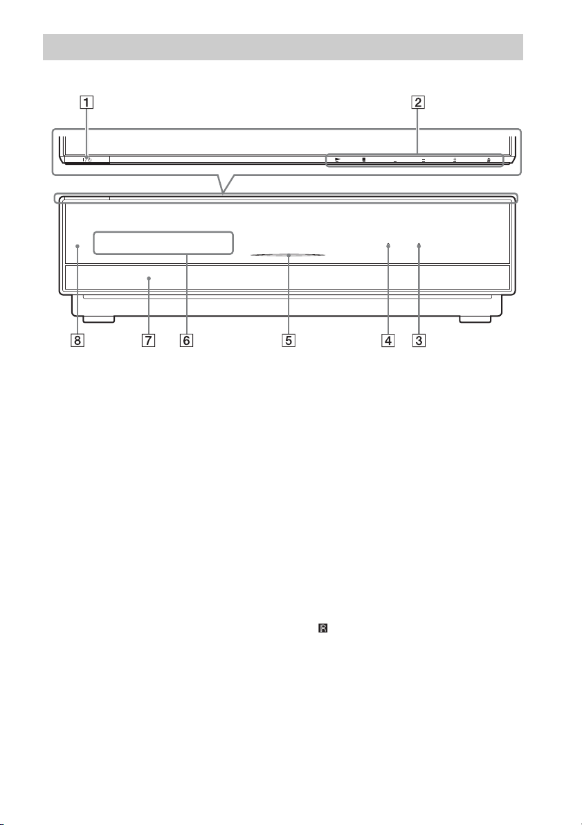
Front panel
FUNCTION VOLUME
HDMI S-AIR
A "/1 (on/standby) (74)
Turns on the unit, or sets to standby mode.
B Soft-touch buttons (74)
These buttons work by touching lightly
around the printed area or projecting part.
Do not press them strongly.
H (play)
Starts or re-starts playback.
Plays a slideshow when a disc containing
JPEG image files is inserted.
x (stop)
Stops playback and remembers the stop
point (resume point).
The resume point for a title/track is the last
point you played or the last photo for a
photo folder.
FUNCTION
Selects the playback source.
VOLUME +/–
Adjusts the system’s volume.
A (open/close)
Opens or closes the disc tray.
C S-AIR indicator
Lights up when the S-AIR transceiver is
inserted in the unit and the system transmits
the sound.
D HDMI indicator
Lights up when the HDMI OUT jack is
correctly connected to HDCP (Highbandwidth Digital Content Protection)
compliant device with HDMI or DVI
(Digital Visual Interface) input.
E DISC indicator
Flashing: The system is loading a disc.
Lighting up: A disc is loaded. (When no
disc is loaded, the DISC indicator is not lit.)
F Front panel display
G Disc tray (74)
H (remote sensor) (16)
GB
9
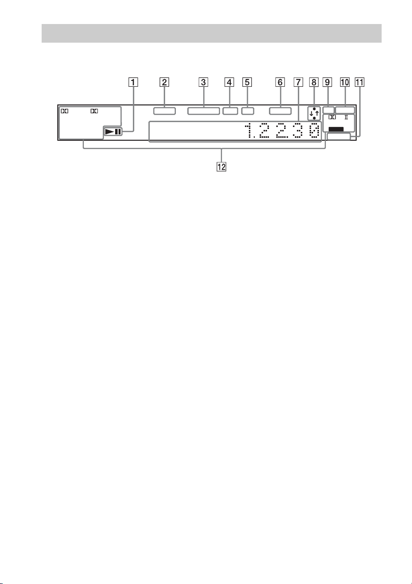
Front panel display
About the indications in the front panel display
+
DEX
–
DTS HD MSTR
–
96 / 24 LBR
ESDTS
–
MATRIX PCML
DISCRETE AAC
Tr ue
HI RES
HD
TUNED MONO EXT HD SLEEP 24P
A Playing status
B Lights up when a station is received.
(Radio only) (92)
C Monaural/Stereo effect (Radio only)
(92)
D Lights up when the external memory is
recognized. (64)
E Lights up when outputting 720p/1080i/
1080p video signals from the HDMI
OUT jack or 720p/1080i video signals
from the COMPONENT VIDEO OUT
jacks.
F Flashes when the sleep timer is set.
(116)
G Displays system’s status such as
chapter, title, or track number, time
information, radio frequency, playing
status, decoding mode, etc.
ST
NIGHT
PL x
NEO:6
D C S
HDMI 1 2
H Lights up when the system is
accessing the network.
I Lights up when outputting 1920 ×
1080p/24Hz video signals.
J Lights up when the night mode is on.
(115)
K Lights up when the HDMI IN1 or 2 jack
is correctly connected to HDCP (Highbandwidth Digital Content Protection)
compliant device with HDMI or DVI
(Digital Visual Interface) output.
L Current sound format
10
GB
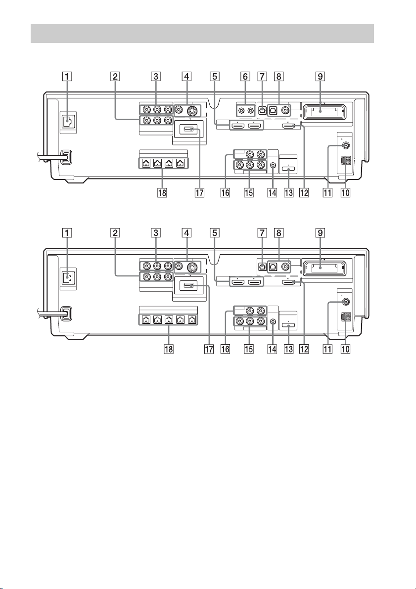
Rear panel
BDV-IT1000
LAN(100)
COMPONENT VIDEO OUT
Y
COMPONENT VIDEO IN
FRONTRFRONT
VIDEO OUT IR REMOTE
P
B
/
PR/
C
B
R
C
Y
B
/ CBPR / C
R
P
SAT/CABLE
SPEAKER
L
DC5V 500mA MAX
CENTER WOOFER
EXTERNAL
BDV-IS1000
COMPONENT VIDEO OUT
Y
LAN(100)
COMPONENT VIDEO IN
FRONT
A LAN (100) terminal (65)
B COMPONENT VIDEO IN (SAT/CABLE)
jacks (59)
C COMPONENT VIDEO OUT jacks (57)
D VIDEO OUT (VIDEO, S VIDEO) jacks
(57)
E HDMI IN1/2 jacks (59)
F IR REMOTE (IN, OUT) (16)
(BDV-IT1000 only)
G DIGITAL IN (TV OPTICAL) jack (57)
H DIGITAL IN (SAT/CABLE OPTICAL,
COAXIAL) jacks (59)
I EZW-RT10 slot (63)
P
C
Y
SAT/CABLE
R
B
/
B
B
/ CBPR / C
P
FRONT
L
PR/
C
R
SPEAKER
CENTER
VIDEO OUT
R
WOOFER1WOOFER
DC5V 500mA MAX
EXTERNAL
SAT/CABLETV
DIGITAL
OPTICAL
IN
LR
LR
OPTICAL
LR
LR
A.CAL
MIC
ECM-AC2
A.CAL
MIC
ECM-AC2
COAXIAL
DMPORT
DC5V
700mA
SAT/CABLETV
COAXIAL
DMPORT
DC5V
700mA
MAX
DIGITAL
MAX
EZW-RT10
IN
EZW-RT10
S-VIDEOVIDEO
S-VIDEOVIDEO
2
HDMI
HDMI
TV
AUDIO IN
VIDEO
TV
AUDIO IN
VIDEO
OUT IN
IN 1 IN 2 OUT
AUDIO
SAT/CABLE IN
IN 1 IN 2 OUT
AUDIO
SAT/CABLE IN
J AM terminal (62)
K FM 75Ω COAXIAL jack (62)
L HDMI OUT jack (57)
M DMPORT (DIGITAL MEDIA PORT) jack
(59)
N A.CAL MIC jack (69, 108)
O SAT/CABLE IN (VIDEO, AUDIO R/L)
jacks (59)
P TV (AUDIO IN R/L) jacks (57)
Q EXTERNAL slot (64)
R SPEAKER jacks (54)
ANTENNA
COAXIAL75
FM
AM
ANTENNA
COAXIAL75
FM
AM
11
GB
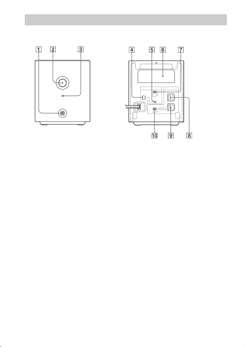
Surround amplifier
Front panel
POWER
POWER/ON LINE
PHONES
A PHONES jack (67)
B POWER (ON/OFF) (67, 102)
C POWER / ON LINE indicator (67, 99)
D PAIRING indicator (102)
E PAIRING (102)
Rear panel
EZW-RT10
S-AIR ID
SURROUND SELECTOR
PAI RI N G
A
B
C
SURROUND
SURROUND
BACK
SPEAKER
L
R
F Wireless transceiver (EZW-RT10) slot
(63)
G S-AIR ID switch (67, 99)
H SPEAKER L jack (54)
I SPEAKER R jack (54)
J SURROUND SELECTOR switch (67,
102)
12
GB
Getting Started
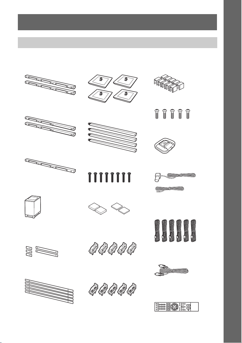
Unpacking
BDV-IT1000
Getting Started
• Front speakers (2)
• Surround speakers (2)
• Center speaker (1)
• Subwoofer (1)
• Baffle covers (short 3, long
2)
• Floor bases (4)
• Poles (4)
• Long screws (8, black)
• Foot pads (thick 2, thin 2)
• Wall mounting brackets
(top) (5)
• Bracket covers (10)
• Screws (5)
• AM loop antenna (aerial) (1)
• FM wire antenna (aerial) (1)
or
• Speaker cords (6, white/red/
blue/gray/green/purple)
• Grilles (5)
• Wall mounting brackets
(bottom) (5)
•Video cord (1)
• Remote commander (remote)
(1)
13
GB
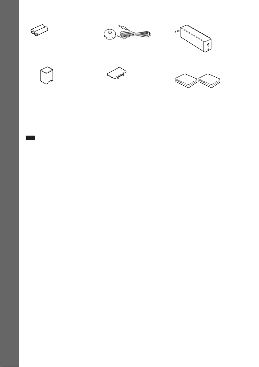
• R6 (size AA) batteries (2) • Calibration mic (1) • Surround amplifier (1)
• Speaker cord cover (1) • Speaker cord holder (1) • Wireless transceivers for the
Getting Started
unit (2)
• Operating Instructions
• Basic connections (card)
• Speaker Installation Guide (card)
• Caution on using the speakers (leaflet)
• Software License Information (leaflet)
Note
• Unpack the speakers, being careful not to touch the speaker units.
• Keep speakers away from one another. Speakers are magnetically attracted, may hit each other, and cause damage.
• Keep magnetic objects such as watches, magnetic card, etc., away from the speakers.
14
GB
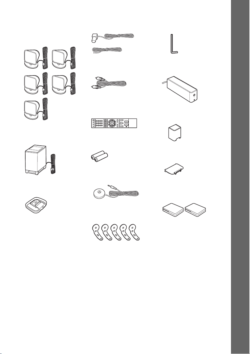
BDV-IS1000
• Front speakers (2), center
speaker (1), and surround
speakers (2)
• Subwoofer (1)
• AM loop antenna (aerial) (1)
• FM wire antenna (aerial) (1)
or
• Video cord (1)
• Remote commander
(remote) (1)
• R6 (size AA) batteries (2)
• Calibration mic (1)
• Wrench (1)
• Surround amplifier (1)
• Speaker cord cover (1)
• Speaker cord holder (1)
• Wireless transceivers for the
unit (2)
Getting Started
• Brackets (5)
• Operating Instructions
• Basic connections (card)
15
GB
Using the remote
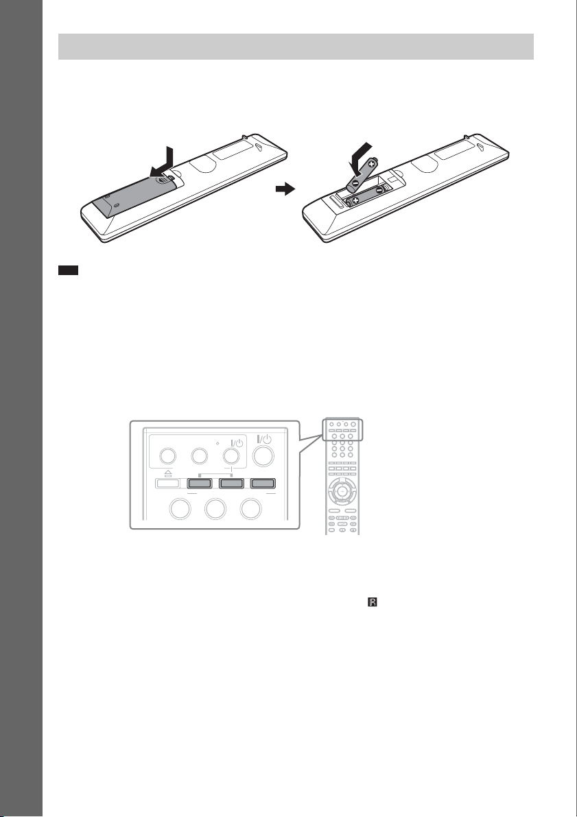
Inserting batteries into the remote
Insert two R6 (size AA) batteries (supplied) by matching the 3 and # ends on the batteries to the
markings inside the compartment.
Getting Started
Note
• Do not leave the remote in an extremely hot or humid place.
• Do not use a new battery with an old one.
• Do not drop any foreign object into the remote casing, particularly when replacing the batteries.
• If you do not intend to use the remote for an extended period of time, remove the batteries to avoid possible damage
from battery leakage and corrosion.
About operation of the remote
You can operate this system, TV, and set-top box/digital satellite receiver using the supplied remote.
Change the operation mode by using OPERATION CHANGE.
THEATRE
BRAVIA Sync
ONE-TOUCH
AV
PLAY
STB TV BD
OPERATION CHANGE
321
321
321
654
987
0
x System operation
Press BD (BD lights up for 1 second).
The remote enters system operation mode, and BD lights up when you press buttons for operation.
When operating the system, point the remote at the remote sensor on the unit.
x TV operation
Press TV (TV lights up for 1 second).
The remote enters TV operation mode, and TV lights up when you press buttons for operation (TV does
not light up when you press a button that is not available for the TV).
To operate the TV, set the remote signal to suit your TV. For details, see “Controlling the TV or Other
Components with the Supplied Remote” (page 111).
GB
16
x Set-top box/digital satellite receiver/Sony component (such as VCR, DVD player/recorder,
etc.) operation
Press STB (STB lights up for 1 second).
The remote enters set-top box/digital satellite receiver operation mode, and STB lights up when you
press buttons for operation (STB does not light up when you press a button that is not available for the
set-top box/digital satellite receiver).
To operate the set-top box/digital satellite receiver/Sony Component, set the remote signal to suit your
set-top box/digital satellite receiver. For details, see “Controlling the TV or Other Components with
the Supplied Remote” (page 111).
Note
• Do not expose the remote sensor to direct sunlight or lighting apparatus. Doing so may cause a malfunction.
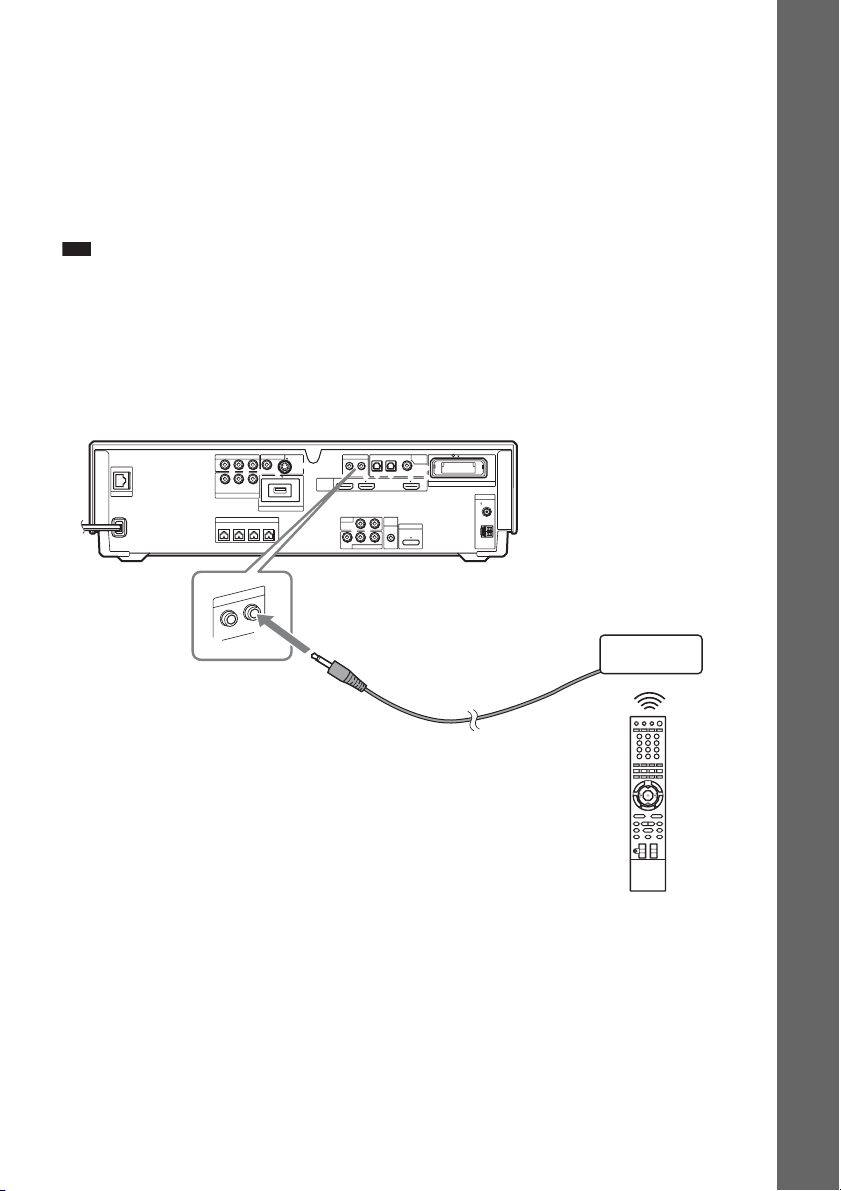
To use the remote at a distance from the system
(BDV-IT1000 only)
You can use the remote away from the system by connecting an IR repeater system (not supplied) to
the unit. Use this optional item when you install the unit in a place where the remote signal cannot be
received.
Rear panel of the unit
VIDEO OUT IR REMOTE
LAN(100)
COMPONENT VIDEO OUT
P
B
/
Y
C
B
Y
B
/ CBPR / C
P
SAT/CABLE
COMPONENT VIDEO IN
SPEAKER
FRONTRFRONT
L
M
E
R
IR
T
U
O
PR/
R
C
CENTER WOOFER
TE
O
IN
R
DC5V 500mA MAX
EXTERNAL
S-VIDEOVIDEO
HDMI
OPTICAL
OUT IN
IN 1 IN 2 OUT
LR
TV
AUDIO IN
LR
AUDIO
VIDEO
SAT/CABLE IN
SAT/CABLETV
DIGITAL
IN
COAXIAL
EZW-RT10
ANTENNA
COAXIAL75
A.CAL
MIC
DMPORT
ECM-AC2
DC5V
700mA
MAX
FM
AM
IR repeater system
Getting Started
17
GB
Step 1: Assembling the Speakers
(BDV-IT1000 only)
You can set speakers in two ways using stands: if you would like to place them on a floor, use speaker
stands (page 23) and if on a desk, shelf, etc., use desktop stands (page 31).
Before connecting the speakers, assemble the speakers.
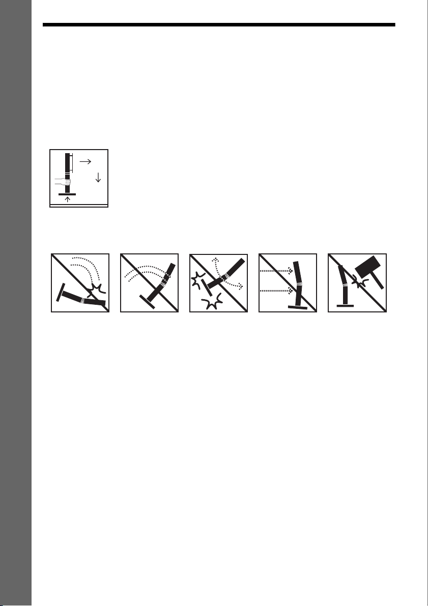
Caution on using the speakers
Getting Started
• When moving the speakers, keep one hand under the desktop stand and hold both sides of the speaker.
When you use speaker stands with the speakers, hold the pole and the base.
• The following actions may damage the speaker.
Toppling the
speaker.
Speaker assembly
Use the parts as follows:
• Front speakers (2)
• Surround speakers (2)
• Center speaker (1)
• Speaker cords (5, white/red/blue/gray/green)
• Baffle covers (short 3, long 2)
•Grilles (5)
Shaking the
speaker.
Swinging the
speaker.
Pushing on the
speaker.
Hitting the speaker.
Use the following if you use speaker stands:
• Floor bases (4)
• Poles (4)
• Long screws (8, black)
Use the following if you use desktop stands:
• Desktop stands (4)
* Desktop stands are screwed on the floor bases. When using desktop stands, unscrew and detach them.
*
Although the front part of the front speaker is slightly different from that of the surround speaker, the
assembly method is the same.
GB
18
About how to connect the speaker cords, see page 54.
p
Note
• Spread a cloth on the floor to avoid damaging the floor when you assemble the speakers.
• When assembling, take care not to touch the speaker units.
Ex. Front speaker
Speaker unit
Ti
• You can install the front, center, and surround speakers on a wall by using the wall mounting bracket (supplied)
(page 42). In this case, you need to attach neither the speaker stand nor desktop stand to the speaker.
How to identify the speakers
Check the label on the speaker.
• Front left speaker (L): FRONT L (white)
• Front right speaker (R): FRONT R (red)
• Surround left speaker (L): SUR L (blue)
• Surround right speaker (R): SUR R (gray)
• Center speaker: CENTER (green)
Getting Started
GB
19
Assembling the center speaker
1 Remove the cover from the speaker.
Pry up the cover by inserting a thin, flat object into the slit in the cover. To replace the cover, see
Step 3. The removed cover is used in a later step, so be careful not to lose it.
Getting Started
Cover
,
Slit
Note
• When assembling, take care not to touch the speaker unit.
2 Connect the speaker cords to the speaker.
Use the speaker cords (green). Be sure to match the speaker cords to the appropriate terminals on
the speakers: the speaker cord with the color tube to 3, and the speaker cord without the color tube
to #. Do not catch the speaker cord insulation in the speaker terminals.
Center speaker
Connector (green)
Note
• When assembling, take care not to touch the speaker unit.
GB
20
Color tube (green)
Center speaker
3
#
Check the polarity on the label.
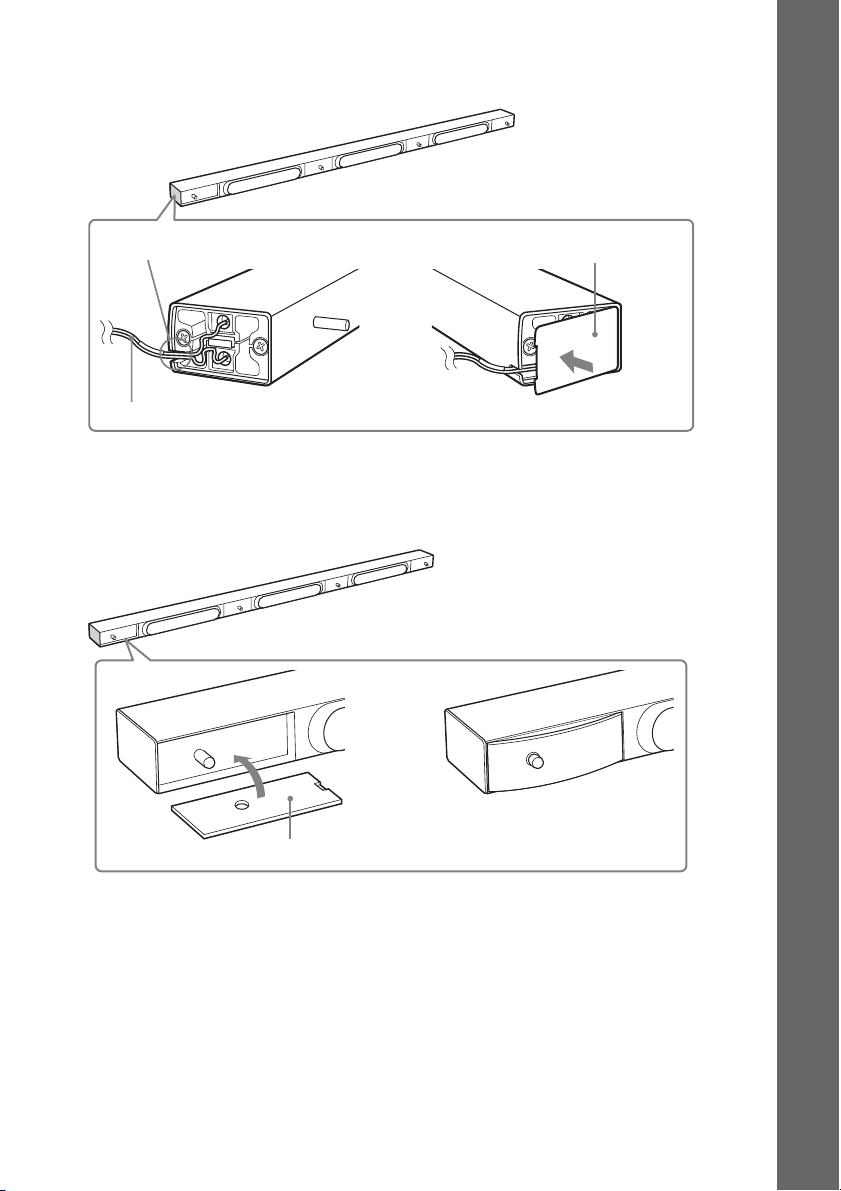
3 Secure the speaker cord by running it through the slot, then attach the cover to the
speaker.
Center speaker
Getting Started
Slot
Cover
,
Speaker cords
4 Attach the baffle cover to the speaker.
Use the baffle cover (short). Press the ends of the baffle cover over the pin, then press down to
flush fit the speaker front.
,
Baffle cover (short)
21
GB
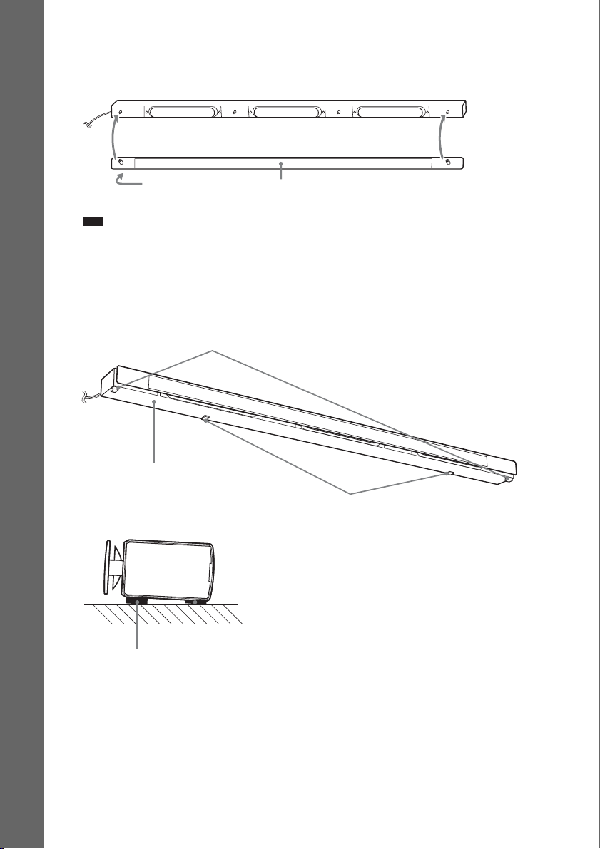
5 Attach the grille to the speaker.
Be careful with the orientation of the grille. The "SONY" logo should be at the left side of the
grille.
Getting Started
“SONY” mark
Note
• When assembling, take care not to touch the speaker unit.
• Be sure to use the speakers with their grilles attached.
• Do not push on the attached grille. It may cause damage to the speaker unit.
Grille
6 Attach the foot pads to the bottom of the speaker.
Attach the foot pads (thick) to the front of the speaker and the foot pads (thin) to the rear so that
the speaker tilts up when installed on a TV stand, etc.
Foot pads (thick)
Side view
GB
22
Bottom of the center speaker
Foot pads (thin)
Foot pads (thin)
Foot pads (thick)
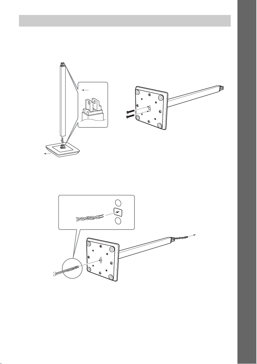
Assembling the front and surround speakers with the speaker stands
1 Attach the pole to the floor base.
When attaching, match the orientation of the protruding parts of the pole and the base.
Secure the pole to the floor base with two long black screws (supplied).
Pole
Front
,
Long screws
Front
Floor base
2 Thread the speaker cord through the hole in the bottom of the floor base and pull the
cord out from the top of the pole.
Twist the split ends of the speaker cord together before you thread the cord.
Getting Started
Speaker cord
23
GB
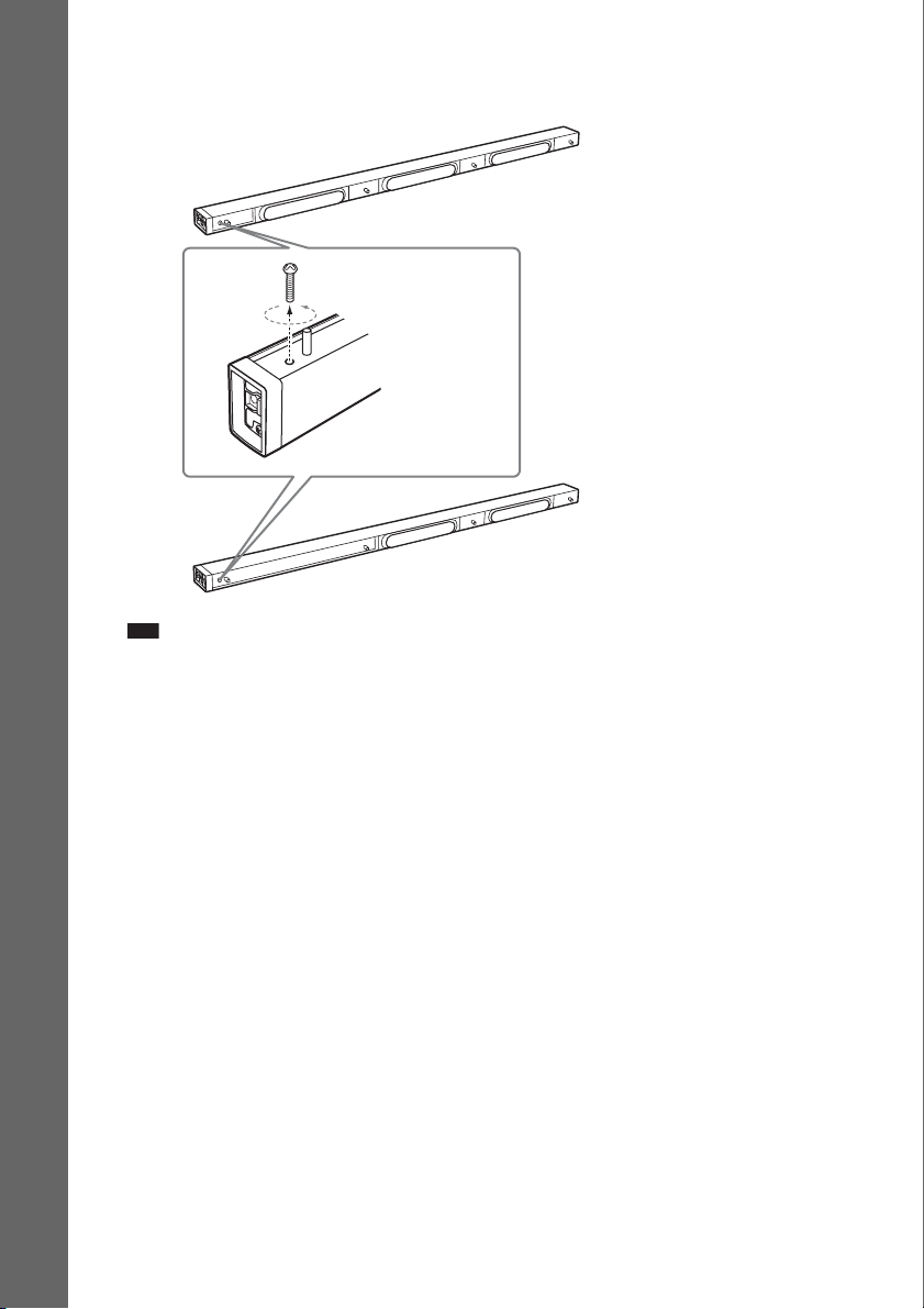
3 Remove the screw from the speaker.
The removed screw is used to attach the speaker to the pole, so be careful not to lose it.
Getting Started
Screw
Note
• When assembling, take care not to touch the speaker unit.
Front speaker
Surround speaker
24
GB
4 Connect the speaker cords to the speaker.
p
The connector and color tube of the speaker cords are the same color as the label of the jacks to be
connected.
Use the speaker cords as follows:
• Front left speaker (L): White
• Front right speaker (R): Red
• Surround left speaker (L): Blue
• Surround right speaker (R): Gray
Be sure to match the speaker cords to the appropriate terminals on the speakers: the speaker cord
with the color tube to 3, and the speaker cord without the color tube to #. Do not catch the
speaker cord insulation in the speaker terminals.
Connector
Front speaker
Color tube
Check the polarity on the label and its color.
Getting Started
Connector
Surround speaker
Insert the speaker cords into the speaker terminal of the speaker as far as they will go. Ensure that
the cords are secure by gently pulling on them one at a time.
Note
• When assembling, take care not to touch the speaker unit.
Ti
• When removing the speaker cords from the speaker terminals, pull out the speaker cords while pressing the
white button on the speaker terminal with a tool such as a flathead screwdriver.
GB
25
5 Attach the speaker to the pole.
When attaching, match the orientation of the pole and speaker.
Secure the speaker with the screw removed in Step 3.
Front speaker Surround speaker
Getting Started
Note
• When assembling, take care not to touch the speaker unit.
Front speaker Surround speaker
,
Screw Screw
Adjust the length of the cord.
6 Take up the slack in the speaker cord by pulling from the bottom of the floor base and
secure it by running through the cord retainers.
Speaker cord
Bottom of the floor base
Cord retainers
GB
26
7 Attach the baffle cover to the speaker.
Use the baffle cover (short) for the front speaker, baffle cover (long) for the surround speaker.
Press the ends of the baffle cover over the pin(s), then press down to flush fit the speaker front.
Front speaker
Baffle cover (short)
Surround speaker
“J” mark
Baffle cover (long)
Getting Started
27
GB
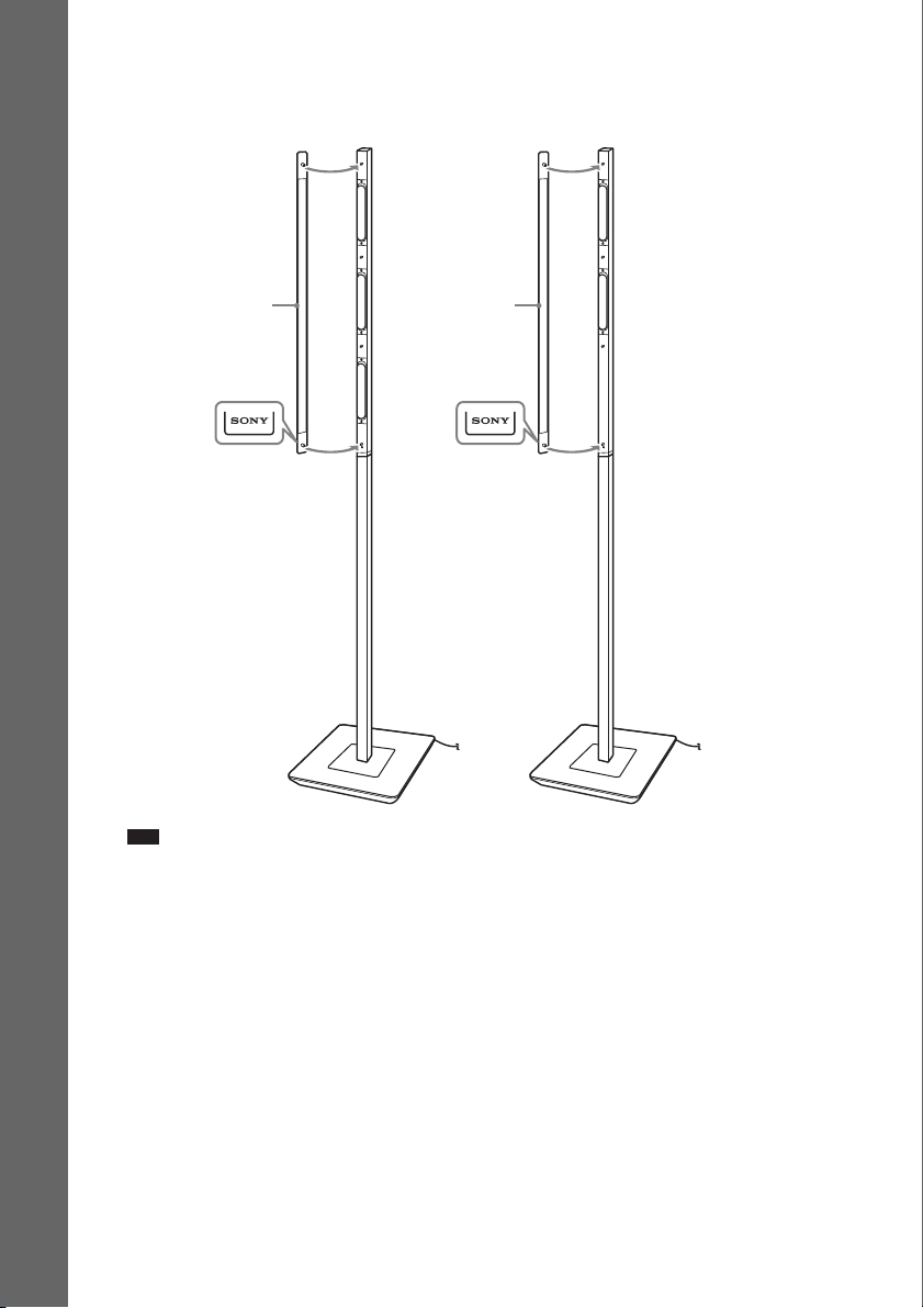
8 Attach the grille to the speaker.
Be careful with the orientation of the grille. The "SONY" logo should be at the bottom of the grille.
Front speaker Surround speaker
Getting Started
Grille
Note
• When assembling, take care not to touch the speaker unit.
• Be sure to use the speakers with their grilles attached.
• Do not push on the attached grille. It may cause damage to the speaker unit.
Grille
28
GB
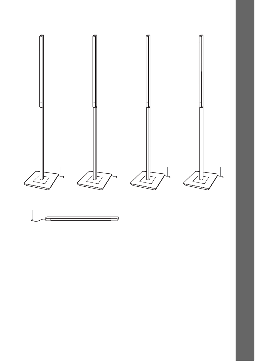
Fully-assembled illustration with the speaker stands
Front left speaker (L):
White label
Front right speaker (R):
Red label
White Red Blue Gray
Surround left speaker (L):
Blue label
Surround right spea ker (R):
Gray label
Getting Started
Green
Center speaker: Green label
29
GB
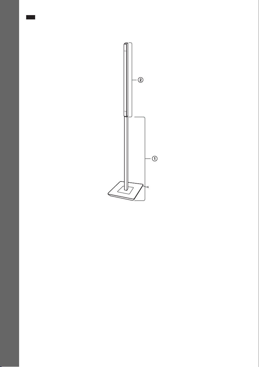
Note
• When moving the speakers, hold the floor base and the pole (1), not the speaker part (2).
Getting Started
30
GB

Assembling the front and surround speakers with the desktop stands
1 Unscrew the short screws from the bottom of the floor base and detach the desktop
stand from the floor base.
Getting Started
Bottom of the floor base
Desktop stand
,
Short screws
Floor base
Note
• Set aside the removed screws so that you do not lose them.
2 Thread the speaker cord through the hole in the bottom of the desktop stand.
Bottom of the desktop stand
Speaker cord
31
GB

3 Remove the screw from the speaker.
The removed screw is used when attaching the desktop stand. Be sure not to lose the screw.
Front speaker
Getting Started
Screw
Surround speaker
Note
• When assembling, take care not to touch the speaker unit.
32
GB

4 Connect the speaker cords to the speaker.
p
The connector and color tube of the speaker cords are the same color as the label of the jacks to be
connected.
Use the speaker cords as follows:
• Front left speaker (L): White
• Front right speaker (R): Red
• Surround left speaker (L): Blue
• Surround right speaker (R): Gray
Be sure to match the speaker cords to the appropriate terminals on the speakers: the speaker cord
with the color tube to 3, and the speaker cord without the color tube to #. Do not catch the
speaker cord insulation in the speaker terminals.
Front speaker
Getting Started
Connector
Color tube
3
#
Check the polarity on the label.
Surround speaker
Insert the speaker cords into the speaker terminal of the speaker as far as they will go. Ensure that
the cords are secure by gently pulling on them one at a time.
Note
• When assembling, take care not to touch the speaker unit.
Ti
• When removing the speaker cords from the speaker terminals, pull out the speaker cords while pressing the
white button on the speaker terminal with a tool such as a flathead screwdriver.
GB
33

5 Attach the speaker to the desktop stand.
When attaching, match the orientation of the desktop stand and speaker.
Secure the speaker with the screw removed in Step 3.
Ex. Front speaker
Getting Started
Adjust the length of the cord.
,
Screw
Note
• When assembling, take care not to touch the speaker unit.
6 Take up the slack in the speaker cord by pulling from the bottom of the desktop stand
and secure the speaker cord by running it through the slot.
Speaker cord
Bottom of the
desktop stand
Slot
Note
• When assembling, take care not to touch the speaker unit.
GB
34

7 Attach the baffle cover to the speaker.
Use the baffle cover (short) for the front speaker, baffle cover (long) for the surround speaker.
Press the ends of the baffle cover over the pin(s), then press down to flush fit the speaker front.
Front speaker
Surround speaker
“J” mark
Getting Started
Baffle cover (short)
Note
• When assembling, take care not to touch the speaker unit.
Baffle cover (long)
8 Attach the grille to the speaker.
Be careful with the orientation of the grille. The "SONY" logo should be at the bottom of the grille.
Front speaker
Grille
Surround speaker
Grille
“SONY” mark
Note
• When assembling, take care not to touch the speaker unit.
• Be sure to use the speakers with their grilles attached.
• Do not push on the attached grille. It may cause damage to the speaker unit.
“SONY” mark
35
GB
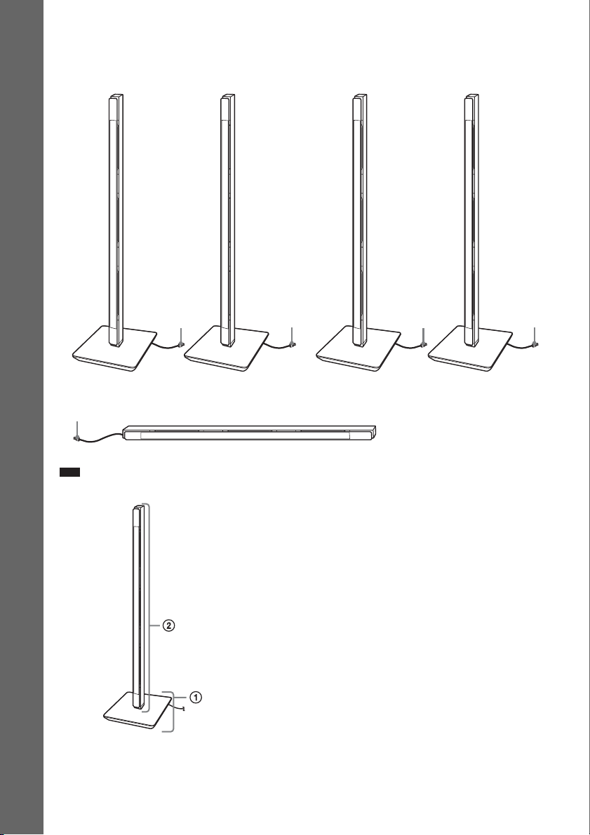
Fully-assembled illustration with the desktop stands
:
Front left speaker (L):
White label
Getting Started
Green
Front right speaker (R):
Red label
White Red
Center speaker: Green label
Surround left speaker (L):
Blue label
Surround right s peaker (R)
Gray label
Blue Gray
Note
• When moving the front or surround speaker, hold the desktop stand part (1), not the speaker part (2).
Ex. Front speaker
GB
36
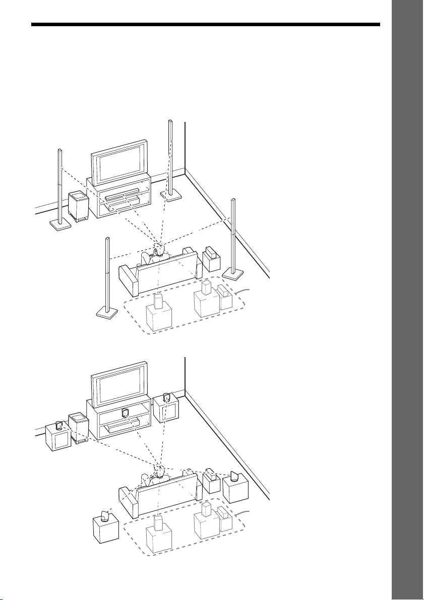
Step 2: Positioning the System
For the best possible surround sound, all the speakers other than the subwoofer should be placed at the
same distance from the listening position (A).
Place the system as illustrated below.
BDV-IT1000
Getting Started
A
F
BDV-IS1000
A
F
D
A
A
A
C
A
C
A
G
G
A
I
A
A
B
A
B
A
A
H
H
A Front left speaker (L)
B Front right speaker (R)
C Center speaker
D Surround left speaker (L)
E Surround right speaker (R)
F Subwoofer
G Unit
H Surround amplifier
E
For surround back speakers
J
K
(optional)
I Surround back left speaker (L)
J Surround back right speaker (R)
K Surround amplifier
A Front left speaker (L)
B Front right speaker (R)
C Center speaker
D Surround left speaker (L)
E Surround right speaker (R)
F Subwoofer
G Unit
H Surround amplifier
E
D
A
A
I
A
J
K
For surround back speakers
(optional)
I Surround back left speaker (L)
J Surround back right speaker (R)
K Surround amplifier
37
GB

About the surround back speaker
p
You can enjoy 7.1 surround sound with the surround back speakers by purchasing the additional
surround amplifier (optional). Use the commercially available speakers for the surround back speakers.
To use the surround amplifier for the surround back speakers, connect the surround back speakers (not
supplied) to the surround amplifier, see “Using an S-AIR Product” (page 99).
Note
• Avoid placing obstructions around the speaker.
• After installing the speakers, arrange the speaker cords so as not to topple the speakers by catching the speaker cords
Getting Started
with your foot.
• Avoid placing the center speaker on the TV.
• Do not set the speakers in an inclined position.
• Avoid placing the speakers in locations that are:
– Extremely hot or cold
– Dusty or dirty
– Very humid
– Subject to vibrations
– Subject to direct sunlight
• Use caution when placing the speakers and/or speaker stands attached to the speakers on a specially treated (waxed,
oiled, polished, etc.) floor, as staining or discoloration may result.
• Do not use any type of abrasive pad, scouring powder, or solvent such as alcohol or benzine.
• Do not lean or hang on the speaker, as the speaker may fall down.
• Do not bend, twist, or fold the speaker grille. (BDV-IT1000 only)
• Do not insert an object (especially metal) into a hole on the front part of the speaker. (BDV-IT1000 only)
• Avoid placing the speakers close to a CRT-based TV. It may cause color irregularity. (BDV-IT1000 only)
• When using the speaker stands, we recommend that the speakers are installed on a flat and firm floor (not on a thick
pile carpet, for example). The speakers may topple over if installed on an inclined or soft floor.
Ti
• When you change the positions of the speakers, Sony recommends that you change the settings. For details, see
“Calibrating the Appropriate Settings Automatically” (page 108) and “Setting the Speakers” (page 110).
GB
38

Using the subwoofer efficiently
To reinforce the bass sound, place the subwoofer as close as possible to a wall.
Close to a wall
Note
• If the subwoofer is to be placed ahead of the front speaker, the distance should be less than 0.5 m (1.6 ft).*
*
Getting Started
• You may not get the bass sound efficiently when the sub woofer is placed outside (3). You need to adjust the setting
of the distance from the listening position.
33
39
GB

• Do not place objects on the top of the subwoofer where the speaker unit is installed.
Getting Started
• Do not place the subwoofer under a desk or in a cabinet, etc.
• Do not place the subwoofer behind an obstruction, such as a TV, etc. Middle range sound will fall.
TV etc.
40
GB

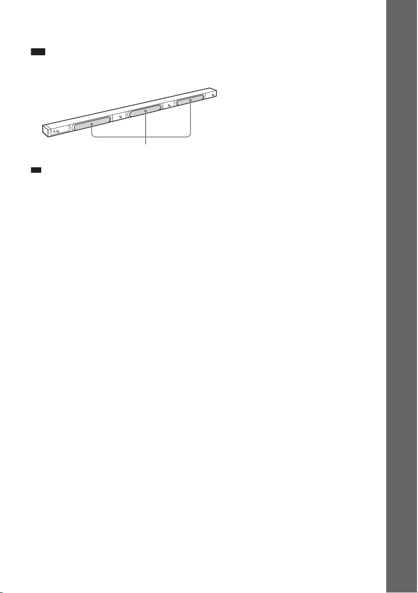
Note on handling the subwoofer
• Do not place your hand into the slit of the subwoofer when lifting it. The speaker driver may be damaged. When
lifting, hold the bottom of the subwoofer.
Subwoofer
Slits
• Do not push the top of the subwoofer where the speaker unit is installed.
Speaker unit
Getting Started
41
GB

p
Installing the speakers on a wall
Caution
• Contact a screw shop or installer regarding the wall material or screws to be used.
• Use screws that are suitable for the wall material and strength. As a plaster board wall is especially fragile, attach
the screws securely to a beam and fasten them to the wall. Install the speakers on a vertical and flat wall where
reinforcement is applied.
• Sony is not responsible for accident or damage caused by improper installation, insufficient wall strength or
Getting Started
improper screw installation, natural calamity, etc.
BDV-IT1000
1 Decide the installation of the speakers.
Recommended example:
Front View
Center speaker
Front left speaker (L)
TV
Front right speaker (R)
Position the front speakers so that their centers align with the TV. Position the center speaker so
that the center of the speaker and the TV are aligned.
Top View
Front left speaker (L)
TV
Front right speaker (R)
The surround speakers should be placed as high (or a little higher) than the front speakers.
Ti
• For details about positioning the speakers, see “Step 2: Positioning the System” (page 37).
GB
42

2 Decide the speaker position and mark the screw positions.
You need two screws (not supplied) for each bracket. The following indicates the narrower
positions of the two screws.
For the front/surround speakers For the center speaker
565 mm
565 mm
3 Remove the cover(s) from the speaker.
Pry up the cover by inserting a thin, flat object into the slit in the cover.
Cover
Slit
Getting Started
Center speaker
Front speaker
Note
• When assembling, take care not to touch the speaker unit.
Surround speaker
43
GB

4 Connect the speaker cords to the speaker.
p
Thread the speaker cord through the holes in the bracket (bottom).
Getting Started
Use the speaker cords as follows:
• Front left speaker (L): White
• Front right speaker (R): Red
• Surround left speaker (L): Blue
• Surround right speaker (R): Gray
• Center speaker: Green
The connector and color tube of the speaker cords are the same color as the label of the jacks to be
connected. Be sure to match the speaker cords to the appropriate terminals on the speakers: the
speaker cord with the color tube to 3, and the speaker cord without the color tube to #. Do not
catch the speaker cord insulation in the speaker terminals.
Ex. Front speaker
Connector
Color tube
Check the polarity on the label.
Center speaker
Left side
Front speaker
Surround speaker
Insert the speaker cords into the speaker terminal of the speaker as far as they will go. Ensure that
the cords are secure by gently pulling on them one at a time.
Note
• When assembling, take care not to touch the speaker unit.
Ti
• When removing the speaker cords from the speaker terminals, pull out the speaker cords while pressing the
white button on the speaker terminal with a tool such as a flathead screwdriver.
GB
44

5 Attach the baffle cover to the speaker.
Use the baffle cover (short) for the front speaker and center speaker, baffle cover (long) for the
surround speaker. Press the ends of the baffle cover over the pin(s), then press down to flush fit
the speaker front.
Front speaker
Baffle cover (short)
Center speaker
Baffle cover (short)
Surround speaker
“J” mark
Baffle cover (long)
Getting Started
45
GB

6 Attach the bracket (bottom) to the speaker.
Insert the bracket (bottom) into the speaker tightly.
Ex. Front speaker
Getting Started
Note
• When attaching the bracket, take care not to catch the speaker cord between the speaker and bracket.
• When assembling, take care not to touch the speaker unit.
7 Attach the bracket (top) to the speaker.
Insert the bracket (top) into the speaker and secure it with the screw (supplied).
Screw
Bracket (bottom)
Speaker cord
Bracket (top)
Front speaker
Note
• When assembling, take care not to touch the speaker unit.
GB
46
Surround speaker
Right side
Center speaker

8 Secure the speaker to the wall.
Check the horizontal and vertical position and tightly attach the speaker to the wall (making sure
the wall is sufficiently thick) using two suitable screws for each bracket (not supplied) in order 1
and 2.
2
Center speaker
1
2
1
Front/Surround speaker
Note
• When attaching the speaker, take care not to catch the speaker cord between the speaker and the wall.
• When assembling, take care not to touch the speaker unit.
9 Attach the bracket cover to the speaker.
Slide the bracket cover from the front of the speaker.
Getting Started
Front/Surround speaker
Center speaker
Bracket cover
47
GB

10 Attach the grille to the speaker.
Be careful with the orientation of the grille. The "SONY" logo should be at the bottom of the grille
for the front/surround speaker, and at the left side of the grille for the center speaker.
Getting Started
Center speaker
Grille
“SONY” mark
Front/Surround speaker
“SONY” mark
Note
• When assembling, take care not to touch the speaker unit.
• Do not push on the attached grille. It may cause damage to the speaker unit.
Grille
48
GB
BDV-IS1000
p
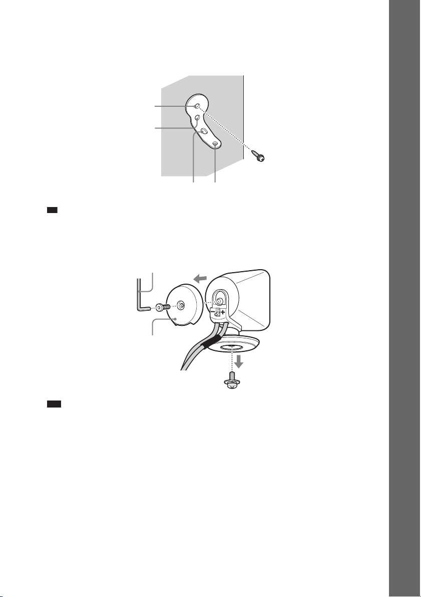
1 Prepare screws (not supplied) that are suitable for the holes of the bracket.
2 Secure the bracket to the wall using hole 1.
1
2
34
Ti
• To prevent the speaker from rotating, use the hole 2, too.
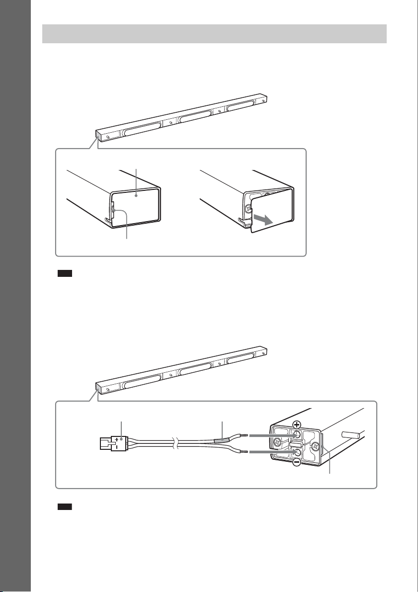
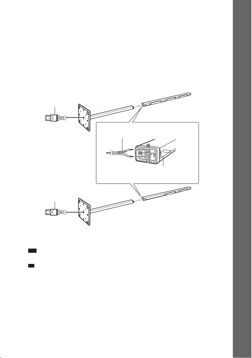
3 Remove the rear cap using the wrench (supplied), and remove the speaker pedestal
using a screwdriver (+) (not supplied).
Wrench (supplied)
Getting Started
Rear cap
Screw
Note
• The removed screw is used in a later step. Be sure not to lose the screw.
GB
49

4 Push A with the supplied wrench (1), and then remove the speaker cords (2).
p
(2)
Getting Started
(1)
When the lever is down, the
speaker cords are locked.
A
When the lever is up, the
speaker cords can be removed.
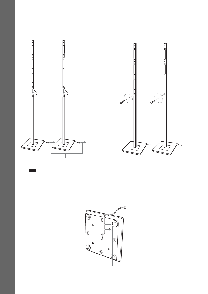
5 Thread the speaker cords through hole 3.
3
6 Reconnect the detached speaker cords, matching 3/# to the appropriate speaker
terminals (1), and then push the lever down completely (2).
(2)
(1)
3
#
Ti
• If it is difficult to push the lever down, use the wrench (supplied).
GB
50

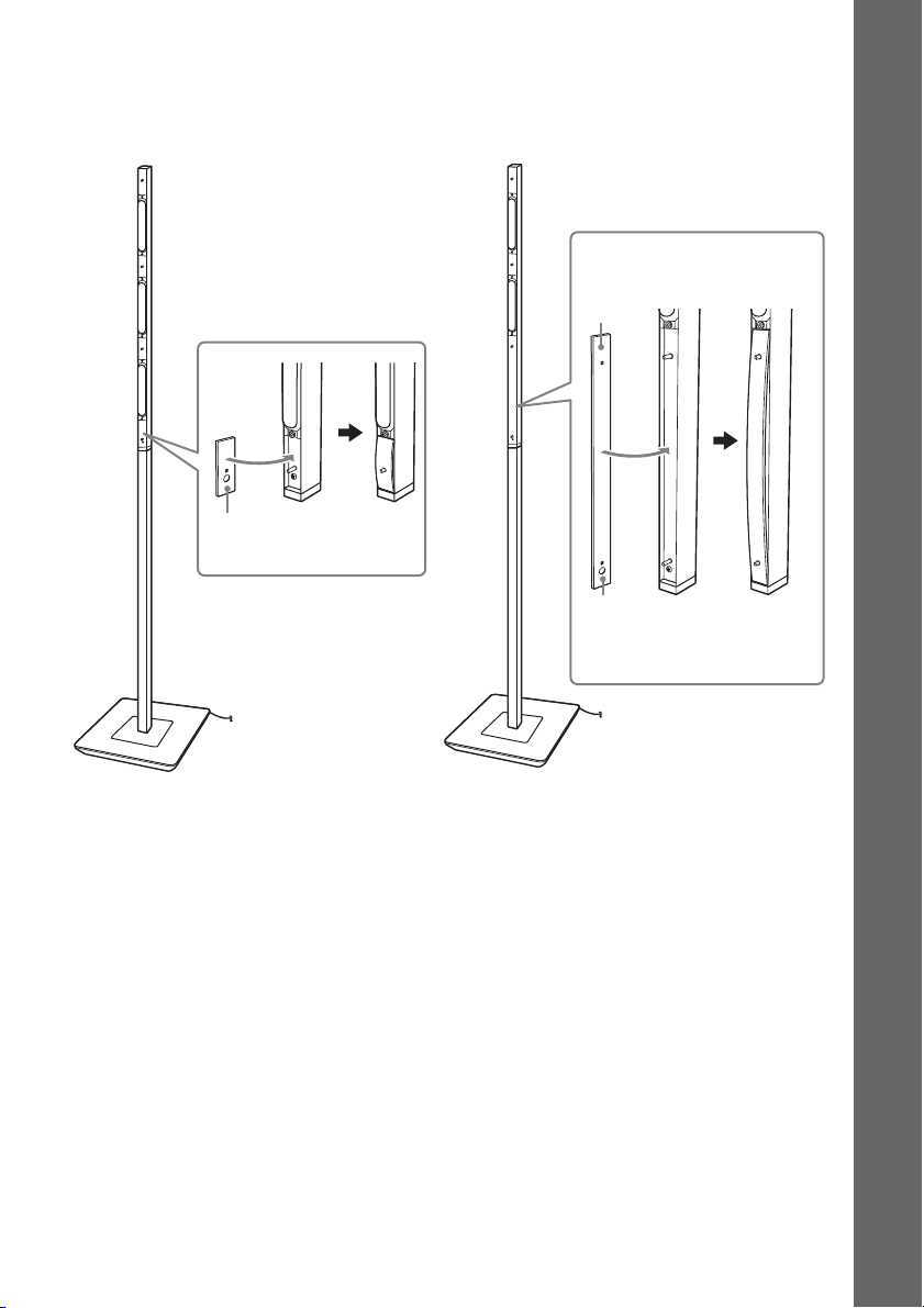
7 Reattach the rear cap using the wrench (supplied).
8 Secure the speaker to the bracket with the screw in Step 3 using hole 4.
4
Getting Started
51
GB

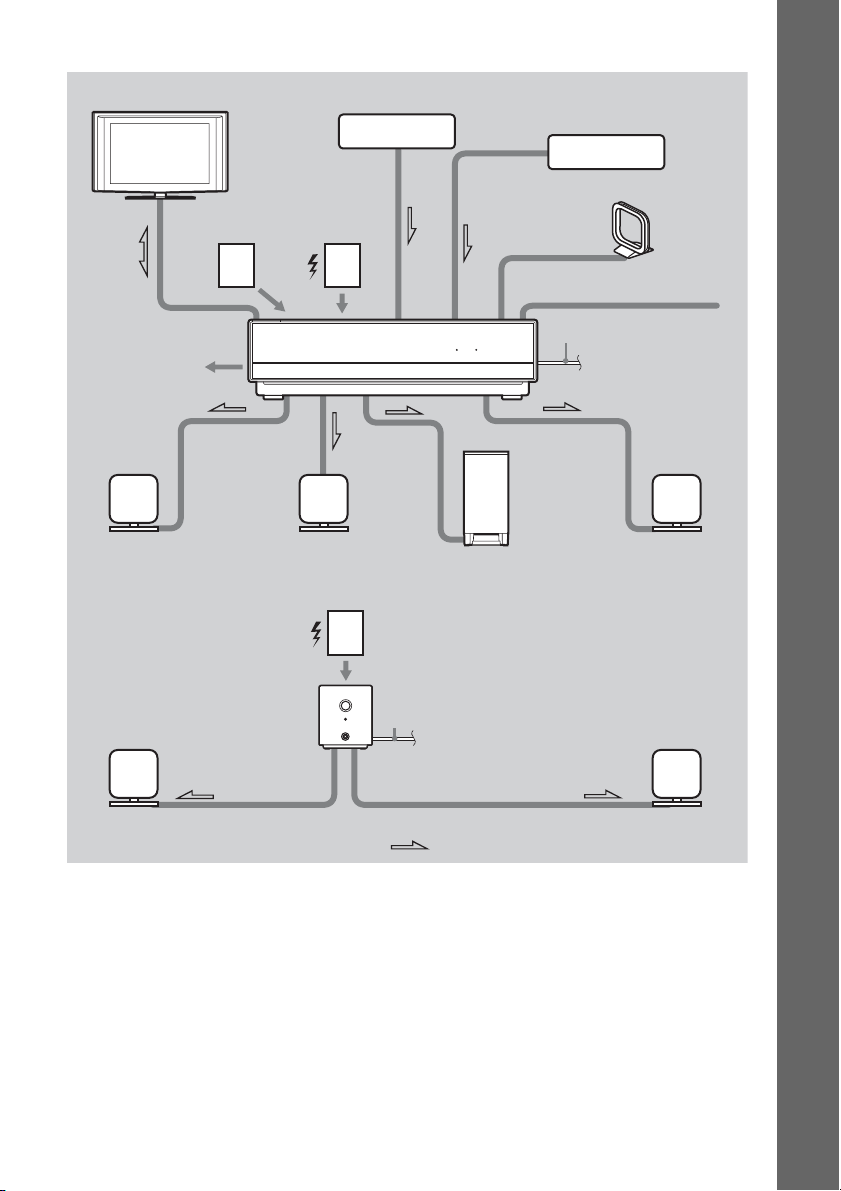
Step 3: Connecting the System
See the connection diagram below, and read the additional information from 1 to 8 on the following
pages.
Note
• Be sure to make connections securely to avoid hum and noise.
• When you connect another component with a volume control, turn up the volume of the other components to a level
Getting Started
where sound is not distorted.
BDV-IT1000
2 TV
6 External
memory
3 DIGITAL MEDIA
PORT adapter
5 Wireless
transceiver
3 Set-top box/digital satellite
receiver, VCR, or PlayStation,
etc.
4 AM loop antenna (aerial)
4 FM wire antenna (aerial)
7 Network
1 Front left speaker (L)
Surround amplifier
1 Surround left speaker (L)
1 Center speaker
5 Wireless
transceiver
HDMI S-AIR
1 Subwoofer
8 AC power cord
(mains lead)
:Signal flow
8 AC power cord (mains lead)
1 Front right speaker (R)
1 Surround right speaker (R)
52
GB
BDV-IS1000
2 TV
6 External
memory
3 DIGITAL MEDIA
PORT adapter
5 Wireless
transceiver
3 Set-top box/digital satellite
receiver, VCR, or PlayStation,
etc.
4 AM loop antenna (aerial)
4 FM wire antenna (aerial)
Getting Started
7 Network
1 Front left speaker (L)
Surround amplifier
1 Surround left speaker (L)
1 Center speaker
5 Wireless
transceiver
HDMI S-AIR
1 Subwoofer
8 AC power cord
(mains lead)
:Signal flow
8 AC power cord (mains lead)
1 Front right speaker (R)
1 Surround right speaker (R)
53
GB
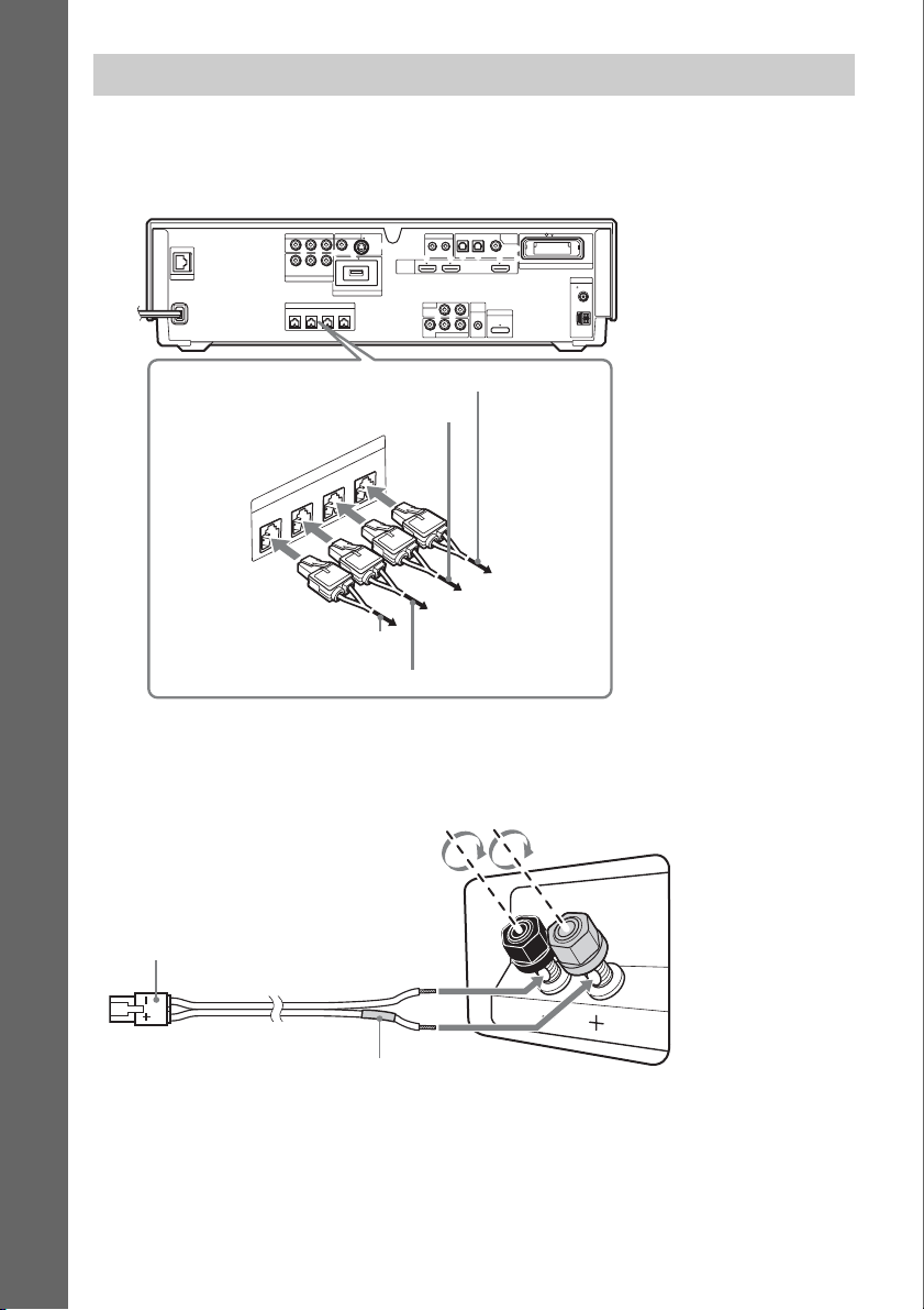
1 Connecting the Speakers
Front/center speakers and subwoofer for BDV-IT1000
When connecting speaker cords to the unit, insert the connector until it clicks.
Rear panel of the unit
VIDEO OUT IR REMOTE
Getting Started
COMPONENT VIDEO OUT
P
B
/
PR/
Y
C
B
R
C
LAN(100)
Y
SAT/CABLE
COMPONENT VIDEO IN
FRONTRFRONT
P
B
/ CBPR / C
SPEAKER
L
R
CENTER WOOFER
DC5V 500mA MAX
EXTERNAL
S-VIDEOVIDEO
To the subwoofer (purple)
To the center speaker (green)
FER
O
R
O
E
W
K
A
TER
E
N
P
E
S
C
T
N
O
FR
L
T
N
O
FR
R
To the front right speaker (R) (red)
To the front left speaker (L) (white)
HDMI
OPTICAL
OUT IN
IN 1 IN 2 OUT
LR
TV
AUDIO IN
LR
AUDIO
VIDEO
SAT/CABLE IN
SAT/CABLETV
DIGITAL
IN
COAXIAL
EZW-RT10
A.CAL
MIC
DMPORT
ECM-AC2
DC5V
700mA
MAX
ANTENNA
FM
AM
COAXIAL75
When connecting the speaker cords to the subwoofer, use the speaker cords (purple). Be sure to match
the speaker cords to the appropriate terminals on the speakers: the speaker cord with the color tube to
3, and the speaker cord without the color tube to #. Do not catch the speaker cord insulation in the
speaker terminals.
Rear of the subwoofer
Connector (purple)
#
3
Color tube (purple)
GB
54

Front/center speakers and subwoofer for BDV-IS1000
When connecting to the unit, insert the connector until it clicks.
Rear panel of the unit
ANTENNA
COAXIAL75
FM
AM
LAN(100)
COMPONENT VIDEO OUT
VIDEO OUT
P
B
/
PR/
Y
C
B
R
C
Y
B
/ CBPR / C
R
P
SAT/CABLE
COMPONENT VIDEO IN
DC5V 500mA MAX
EXTERNAL
SPEAKER
FRONTRWOOFER1WOOFER
FRONT
CENTER
2
L
To the subwoofer (purple)
R
WOOFER
E
K
R
A
TE
E
P
EN
S
C
T
N
O
FR
L
T
N
O
FR
R
SAT/CABLETV
DIGITAL
OPTICAL
IN
SAT/CABLE IN
COAXIAL
LR
A.CAL
MIC
DMPORT
ECM-AC2
DC5V
700mA
LR
MAX
AUDIO
S-VIDEOVIDEO
IN 1 IN 2 OUT
HDMI
TV
AUDIO IN
VIDEO
To the subwoofer (yellow)
WOOFER
2
1
EZW-RT10
Getting Started
To the front right speaker (R) (red)
To the center speaker (green)
To the front left speaker (L) (white)
The speaker cords (yellow and purple) are connected to the subwoofer beforehand as follows. When
re-connecting, be sure to match the speaker cords to the appropriate terminals on the speakers: the
speaker cord with the color tube to 3, and the speaker cord without the color tube to #. Do not catch
the speaker cord insulation in the speaker terminals.
Connector (yellow)
Connector (purple)
Color tube
(yellow)
Color tube
(purple)
#
3
#
3
Rear of the subwoofer
55
GB

Surround speakers
Rear panel of the surround amplifier
EZW-RT
S-AIR ID
SURROUND SELECTOR
10
SPEAKER
A
B
C
PAIRIN G
SURROUND
SURROUND
BACK
To the surround left speaker (L)
L
(blue)
R
S
P
E
A
K
E
R
L
R
Getting Started
To the surround right speaker (R) (gray)
About the speaker cords of the front/center speakers and subwoofer
You can remove the speaker cords from the connector. With the catch facing down, press and hold the
connector down against a flat surface (1) and remove the speaker cords from the connector (2).
(1)
(2)
Catch
When attaching the speaker cords to the connector, be sure to match the polarity of the speaker cords
and the connector.
3
#
Connector
Note
• Short-circuiting of the speakers may damage the system. To prevent this, make sure the bare wire of each speaker
cord does not touch another speaker terminal or the bare wire of another speaker cord.
• Be sure to match the speaker cords to the appropriate speaker terminals: 3 to +, and # to –. If the cords are
reversed, the sound will lack bass and may be distorted.
GB
56
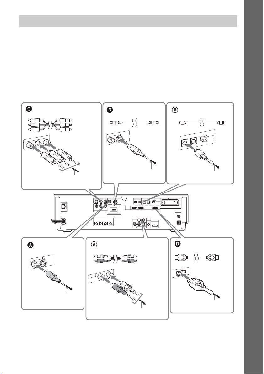
2 Connecting the TV
Use the parts as follows:
•Video cord (1)
To listen to TV sound from the six speakers of the system, connect the TV and the system with the
audio cord (not supplied) (A).
For video output to your TV, check the video input jacks of the TV, and select connection method A,
B, C, or D. Picture quality improves in order from A (standard) to D (HDMI).
When the TV has the digital optical output jack, you can improve sound quality by connecting with the
digital optical cord (not supplied) (B).
Getting Started
Component video cord
(not supplied)*
Green
Blue
Red
/
R
P
COMPONENT VIDEO OUT
/
R
B
C
P
B
C
Y
To the component video input jacks of
the TV
LAN(100)
Video cord
(supplied)
VIDEO OUT
V
O
E
ID
-V
S
O
E
ID
TV
IN
IO
D
U
A
S video cord
(not supplied)
VIDEO OUT
O
E
ID
V
To the S video input jack
of the TV
VIDEO OUT IR REMOTE
COMPONENT VIDEO OUT
P
B
/
PR/
Y
C
B
R
C
Y
SAT/CABLE
COMPONENT VIDEO IN
FRONTRFRONT
S-VIDEOVIDEO
B
/ CBPR / C
R
P
DC5V 500mA MAX
EXTERNAL
SPEAKER
CENTER WOOFER
L
Audio cord
(not supplied)
L
R
-V
S
O
E
ID
HDMI
OPTICAL
OUT IN
IN 1 IN 2 OUT
LR
TV
AUDIO IN
LR
AUDIO
VIDEO
SAT/CABLE IN
White
Red
Digital optical cord
(not supplied)
DIGITAL
IN
SAT/CABLE
TV
OPTICAL
COAXIAL
To the digital optical output
jack of the TV
SAT/CABLETV
DIGITAL
IN
COAXIAL
EZW-RT10
A.CAL
MIC
DMPORT
ECM-AC2
DC5V
700mA
MAX
Rear panel of the unit
(Ex. BDV-IT1000)
ANTENNA
COAXIAL75
FM
AM
HDMI** cable
(not supplied)
T
U
O
To the video input jack of
the TV
To the audio output jacks of the TV
* If your TV accepts progressive format signals, make this connection.
** HDMI (High-Definition Multimedia Interface)
If your TV has the HDMI jack, make this connection.
To the HDMI IN jack of the TV
57
GB

About the HDMI connection
If you connect a 1080/24p- or 1080p-compatible TV, use a High Speed HDMI cable.
If you connect a Sony TV that is compatible with the Control for HDMI function (page 105), operation
is simplified (ex. ONE-TOUCH PLAY: With one touch of the button, the connected TV turns on and
the input selector on the TV is switched to the system automatically). For details, see “Using the
Control for HDMI Function for “BRAVIA” Sync” (page 105).
Note
• Be sure to use only an HDMI cable that bears the HDMI logo.
Getting Started
• When connecting the HDMI cable, make sure that the direction of jacks are the same.
.
To connect to a TV with DVI input
Use an HDMI-DVI converter cable (not supplied). The DVI jack does not accept audio signals;
therefore, the sound is not output from a TV.
Furthermore, you cannot connect the HDMI OUT jack to DVI jacks that are not HDCP compliant (e.g.,
DVI jacks on PC displays).
58
GB

3 Connecting the other components
You can enjoy the connected component(s) using the six speakers of the system.
• Set-top box/digital satellite receiver, VCR, or PlayStation, etc. (without HDMI OUT jack): 1
• Set-top box/digital satellite receiver or PLAYSTATION
• DIGITAL MEDIA PORT adapter: 3
Audio connection
1
A Audio cord
(not supplied)
HDMI cable
2
(not supplied)
I
M
D
H
IN 1 IN 2
O
E
ID
V
To the audio output jacks of the
component
LR
IO
D
U
A
IN
LE
B
A
T/C
A
S
®
3, etc. (with HDMI OUT jack): 2
B Digital optical cord
(not supplied)
White
Red
B Digital coaxial cord
(not supplied)
DIGITAL
IN
SAT/CABLE
TV
OPTICAL
COAXIAL
or
Getting Started
To the HDMI OUT jack
of the component
COMPONENT VIDEO OUT
Y
Video connection
1
LAN(100)
COMPONENT VIDEO IN
FRONTRFRONT
B Component video cord
(not supplied)
Green
Blue
Red
R
/ C
R
P
B
/ C
B
P
Y
LE
B
A
AT/C
S
IN
EO
ID
T V
EN
N
PO
M
O
C
To the component video output jacks of
the component
To the digital optical output jack of the component
VIDEO OUT IR REMOTE
P
B
/
PR/
C
C
B
R
B
/ CBPR / C
P
SPEAKER
L
R
CENTER WOOFER
DC5V 500mA MAX
EXTERNAL
S-VIDEOVIDEO
Y
SAT/CABLE
A Video cord
(not supplied)
LR
IO
D
U
A
IN
LE
B
A
T/C
A
O
S
E
ID
V
To the video output
jack of the component
To the digital coaxial output jack of the component
Rear panel of the unit
(Ex. BDV-IT1000)
ANTENNA
COAXIAL75
FM
AM
HDMI
OPTICAL
OUT IN
IN 1 IN 2 OUT
LR
TV
AUDIO IN
LR
AUDIO
VIDEO
SAT/CABLE IN
SAT/CABLETV
DIGITAL
IN
COAXIAL
EZW-RT10
A.CAL
MIC
DMPORT
ECM-AC2
DC5V
700mA
MAX
3
DMPORT
DC5V
700mA
MAX
DIGITAL MEDIA PORT
adapter
59
GB

Connection 1 (SAT/CABLE jacks)
You need to make both video and audio connections.
For video connection, check the video output jacks of the component, and select a connection method.
B (component) offers the better picture quality than A (standard).
For audio connection, connect the audio cords (A). If the component has a digital optical or coaxial
output jack, you can improve sound quality by connecting with the digital cord (B).
Note
• The system can accept both digital and analog signals. Digital signals have priority over analog signals. (COAXIAL
Getting Started
has priority over OPTICAL.) If the digital signal ceases, the analog signal will be processed after 2 seconds.
Connection 2 (HDMI IN1/2 jacks)
When connecting the system and the component using an HDMI cable, you can enjoy high quality
digital pictures and sound through the HDMI IN1 or 2 jack. You can connect up to two components.
Note
• When connecting the HDMI cable, make sure that the direction of jacks are the same.
.
Connection 3 (DMPORT jack)
Connect a DIGITAL MEDIA PORT adapter (not supplied) to the DMPORT jack. For details, see
“Using the DIGITAL MEDIA PORT Adapter” (page 98).
Note
• Connect the DIGITAL MEDIA PORT adapter so that the V marks are aligned. When disconnecting, pull out while
pressing A.
60
A
GB

Relationship between input and output video signal
The relationship between input and output video signal for each function is as follows.
Jack(s) that accept
Function
“BD/DVD”
“TUNER FM”
“TUNER AM”
“SAT/CABLE”
video signal input
None (only video signal
output)
SAT/CABLE IN
(VIDEO)
COMPONENT VIDEO
IN (SAT/CABLE)
“DMPORT”
“HDMI1”
”HDMI2”
DMPORT a ––a
HDMI1, HDMI2 – – – a
a: Video signals are output.
–: Video signals are not output.
* Depending on the setting of the video output resolution, video signals may be not output. For details, see “Video
Output Resolution” (page 144).
Jack(s) where video signal is output
VIDEO OUT
(VIDEO)
VIDEO OUT
(S VIDEO)
COMPONENT
VIDEO OUT
HDMI OUT
a* a* a* a
a ––a
––aa
Relationship between input and output audio signal
The relationship between input and output audio signal for each function is as follows.
Getting Started
Function
“BD/DVD”
Jack(s) that accept
audio signal input
None (only audio signal
Jack(s) where audio signal is output
SPEAKER
SPEAKER and
HDMI OUT
a *
output)
“TUNER FM”
“TUNER AM”
“TV’
None (only audio signal
output)
DIGITAL IN (TV
a –
a –
OPTICAL)
TV (AUDIO IN R/L) a –
“SAT/CABLE”
DIGITAL IN (SAT/
a –
CABLE OPTICAL,
COAXIAL)
SAT/CABLE IN
a –
(AUDIO R/L)
“DMPORT”
“HDMI1”
”HDMI2”
DMPORT a –
HDMI1, HDMI2 a *
a: Audio signals are output.
–: Audio signals are not output.
* You can output sound from both the system’s speakers and TV speaker if you connect the system and TV with an
HDMI cable (not supplied). To output sound from the HDMI OUT jack, set [Audio (HDMI)] in [HDMI Settings]
to [TV+AMP]. If the TV has stereo speakers, the sound output from the system’s speakers will also be stereo, even
if you play a multi-channel source. For details on [Audio (HDMI)], see page 125.
61
GB

p
4 Connecting the antenna (aerial)
ANTENNA
COAXIAL
75
FM
FM wire antenna (aerial)
(supplied)
Getting Started
LAN(100)
COMPONENT VIDEO OUT
P
B
/
Y
C
B
Y
B
/ CBPR / C
P
SAT/CABLE
COMPONENT VIDEO IN
SPEAKER
FRONTRFRONT
L
PR/
R
C
CENTER WOOFER
R
VIDEO OUT IR REMOTE
DC5V 500mA MAX
EXTERNAL
or
SAT/CABLETV
DIGITAL
OPTICAL
IN
AUDIO
SAT/CABLE IN
COAXIAL
EZW-RT10
LR
A.CAL
MIC
DMPORT
ECM-AC2
DC5V
700mA
LR
MAX
S-VIDEOVIDEO
OUT IN
IN 1 IN 2 OUT
HDMI
TV
AUDIO IN
VIDEO
Rear panel of the unit
(Ex. BDV-IT1000)
ANTENNA
COAXIAL75
FM
AM
AM loop antenna (aerial)
(supplied)
A
AM
B
Note
• Cord (A) or cord (B) can be connected to either
terminal.
Note
• Keep the AM loop antenna (aerial) and cord away from the system or other AV components, as noise may result.
• Be sure to fully extend the FM wire antenna (aerial).
• After connecting the FM wire antenna (aerial), keep it as horizontal as possible.
Ti
• Adjust the direction of the AM loop antenna (aerial) for best AM broadcast sound.
• If you have poor FM reception, use a 75-ohm coaxial cable (not supplied) to connect the unit to an outdoor FM
antenna (aerial) as shown below.
Outdoor FM antenna (aerial)
Unit
ANTENNA
COAXIAL75
FM
GB
62

5 Inserting the wireless transceiver
You can transmit sound from the unit to an S-AIR product, such as a surround amplifier or S-AIR
receiver.
An S-AIR product is a component that is compatible with the S-AIR function.
To use the S-AIR function, you need to insert the wireless transceivers into the unit, surround amplifier,
and S-AIR receiver.
For details of the S-AIR function, see “Using an S-AIR Product” (page 99).
Getting Started
Rear panel of the unit (Ex. BDV-IT1000)
VIDEO OUT IR REMOTE
COMPONENT VIDEO OUT
P
B
/
PR/
Y
C
B
R
C
S-VIDEOVIDEO
LAN(100)
Y
B
/ CBPR / C
P
SAT/CABLE
COMPONENT VIDEO IN
SPEAKER
FRONTRFRONT
CENTER WOOFER
L
EZW-RT10
R
DC5V 500mA MAX
EXTERNAL
HDMI
Wireless
transceiver
OPTICAL
OUT IN
IN 1 IN 2 OUT
LR
TV
AUDIO IN
LR
AUDIO
VIDEO
SAT/CABLE IN
SAT/CABLETV
DIGITAL
IN
COAXIAL
EZW-RT10
ANTENNA
COAXIAL75
A.CAL
MIC
DMPORT
ECM-AC2
DC5V
700mA
MAX
FM
AM
E
Wireless
transceiver
10
T
-R
W
Z
Rear panel of the
surround amplifier
EZW-RT
10
S-AIR ID
SPEAKER
A
B
C
L
PAIRIN G
SURROUND SELECTOR
R
SURROUND
SURROUND
BACK
Note
• When you insert the wireless transceiver, make sure that the AC power cord (mains lead) is not connected to a wall
outlet (mains).
• Do not touch the terminals of the wireless transceiver.
• Insert the wireless transceiver with the S-AIR logo facing up.
• Insert the wireless transceiver so that the V marks are aligned.
• Do not insert other than the wireless transceiver into the EZW-RT10 slot.
63
GB

6 Inserting the external memory
Insert the external memory (local storage) (not supplied: USM1GH (as of April 2008)) into the
EXTERNAL slot. By connecting an external memory, you can enjoy additional contents (BonusView/
BD-Live) depending on the disc.
Rear panel of the unit (Ex. BDV-IT1000)
Getting Started
LAN(100)
USM1GH
(as of April 2008)
Note
• Insert the external memory in the V direction into the EXTERNAL slot as far as it will go.
• Check that “EXT” lights up in the front panel display when turning the system on.
VIDEO OUT IR REMOTE
COMPONENT VIDEO OUT
P
B
/
PR/
Y
C
B
R
C
Y
B
/ CBPR / C
R
P
SAT/CABLE
COMPONENT VIDEO IN
SPEAKER
FRONTRFRONT
CENTER WOOFER
L
With the terminal
side up
DC5V 500mA MAX
EXTERNAL
S-VIDEOVIDEO
DC5V
HDMI
AUDIO IN
500mA MAX
EXTERNAL
OPTICAL
OUT IN
IN 1 IN 2 OUT
LR
TV
A.CAL
ECM-AC2
LR
AUDIO
VIDEO
SAT/CABLE IN
SAT/CABLETV
DIGITAL
IN
COAXIAL
EZW-RT10
ANTENNA
COAXIAL75
MIC
DMPORT
DC5V
700mA
MAX
FM
AM
To enjoy BonusView/BD-Live
See “Enjoying BonusView/BD-Live” (page 78).
To remove the external memory
1 Press "/1 to turn the system off.
2 Pull out the external memory from the EXTERNAL slot.
Note
• Insert the external memory straight. If you force the external memory into the slot, this will cause damage to both
the external memory and the unit.
• Keep the external memory away from small children to prevent them from accidentally swallowing the external
memory.
• Do not apply too much pressure to the external memory in the slot, as it may cause a malfunction.
• Use the USM1GH (as of April 2008) external memory only.
• To avoid data corruption or damage to the external memory, turn the system off when inserting or removing the
external memory.
• Do not insert the external memory that contains photo or music files to avoid corrupting the external memory data.
GB
64
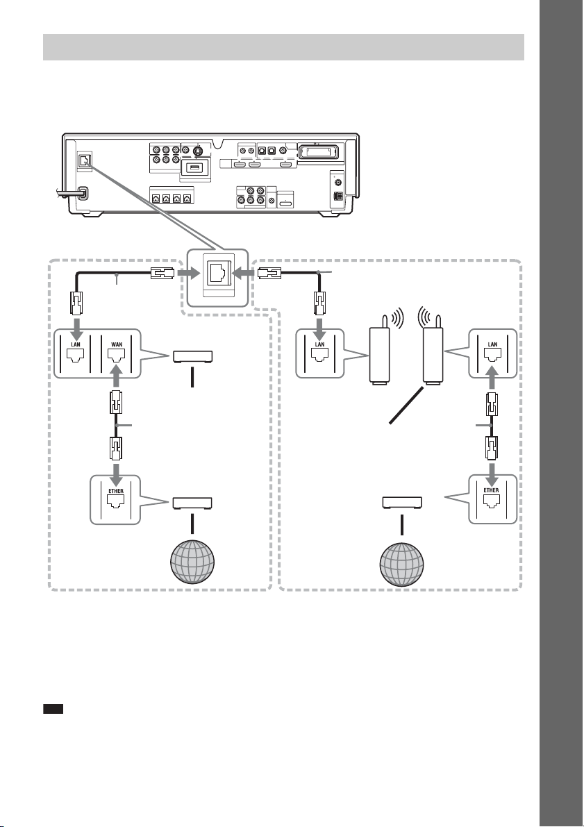
7 Connecting to the network
Connect the LAN (100) terminal of the unit to your Internet source using a network cable to update the
system’s software using the network. You can also enjoy BD-Live (page 78).
Make the appropriate settings in [Internet Settings] under [Network Settings] (page 127).
Getting Started
COMPONENT VIDEO OUT
P
B
/
PR/
Y
C
B
R
C
Y
B
/ CBPR / C
P
LAN(100)
When connecting to a
broadband router directly
SAT/CABLE
COMPONENT VIDEO IN
SPEAKER
FRONTRFRONT
L
Network cable
(not supplied)
Broadband router
(not supplied)
To PC
Network cable
(not supplied)
ADSL modem/
Cable modem
(not supplied)
VIDEO OUT IR REMOTE
S-VIDEOVIDEO
DC5V 500mA MAX
EXTERNAL
HDMI
LAN(100)
R
CENTER WOOFER
OPTICAL
OUT IN
IN 1 IN 2 OUT
LR
TV
A.CAL
AUDIO IN
ECM-AC2
LR
AUDIO
VIDEO
SAT/CABLE IN
SAT/CABLETV
DIGITAL
IN
COAXIAL
EZW-RT10
MIC
DMPORT
DC5V
700mA
MAX
Rear panel of the unit
(Ex. BDV-IT1000)
ANTENNA
COAXIAL75
FM
AM
When connecting via a wireless
LAN router
Network cable
(not supplied)
Ethernet/wireless
LAN media converter
(not supplied)
To PC
ADSL modem/
Cable modem
(not supplied)
Wireless LAN router
(access point)
(not supplied)
Network cable
(not supplied)
Internet
Internet
To update the system’s software using the network
See [Network Update] (page 118) and [Software Update Notification] (page 126).
To enjoy BD-Live
See “Enjoying BonusView/BD-Live” (page 78).
Note
• Do not connect a phone line to the LAN (100) terminal, as it may cause a malfunction.
• Depending on the modem or router, the type of network (LAN) cable, straight or crossing, differs. For details on
the network (LAN) cables, refer to the operating instructions supplied with the modem or router.
• Do not connect the LAN terminal of the unit to the LAN terminal of the PC.
65
GB

• To enjoy the BD-Live function, we recommend using an Internet connection with an effective speed of 1 Mbps or
greater, depending on your connection environment and network condition.
8 Connecting the AC power cords (mains leads)
Before connecting the AC power cords (mains leads) of the unit and the surround amplifier to a wall
outlet (mains), connect the front, center speakers and subwoofer to the unit and surround speakers to
the surround amplifier.
Getting Started
Rear panel of the unit (Ex. BDV-IT1000)
VIDEO OUT IR REMOTE
COMPONENT VIDEO OUT
P
B
/
PR/
Y
C
B
R
C
S-VIDEOVIDEO
LAN(100)
Y
B
/ CBPR / C
P
SAT/CABLE
COMPONENT VIDEO IN
SPEAKER
FRONTRFRONT
L
R
CENTER WOOFER
DC5V 500mA MAX
EXTERNAL
HDMI
OPTICAL
OUT IN
IN 1 IN 2 OUT
LR
TV
A.CAL
AUDIO IN
LR
AUDIO
VIDEO
SAT/CABLE IN
Rear panel of the
SAT/CABLETV
DIGITAL
IN
COAXIAL
EZW-RT10
ANTENNA
COAXIAL75
MIC
DMPORT
ECM-AC2
DC5V
700mA
MAX
FM
AM
surround amplifier
EZW-RT
S-AIR ID
PAIRIN G
SURROUND SELECTOR
10
SPEAKER
A
B
C
L
R
SURROUND
SURROUND
BACK
To the wall outlet (mains)
To the wall outlet (mains)
66
GB

Step 4: Setting up the Wireless System
To use the wireless system, you need to set up
the surround amplifier. Before setting, make
sure that the wireless transceivers are inserted
into the unit and the surround amplifier correctly
(page 63).
This wireless system is called “S-AIR.” For
details of the S-AIR function, see “Using an
S-AIR Product” (page 99).
"/1
HDMI S-AIR
POWER / ON LINE
Indicator
POWER
POWER
POWER/ON LINE
PHONES
PHONES jack
The unit transmits sound to the surround
amplifier that is connected to the surround
speakers. To establish sound transmission,
perform the following Steps.
1 Press "/1 on the unit.
The system turns on.
2 Make sure that the SURROUND
SELECTOR switch of the surround
amplifier is set to SURROUND.
3 Set the S-AIR ID switch of the surround
amplifier to A.
4 Press POWER on the surround
amplifier.
The POWER / ON LINE indicator turns
green. If not, check the transmission status
as follows.
S-AIR ID switch
EZW-RT
10
S-AIR ID
SPEAKER
A
B
C
PAIRIN G
SURROUND SELECTOR
SURROUND
SURROUND
BACK
SURROUND
SELECTOR switch
L
R
To check the transmission status
You can check the status of sound transmission
between the unit and surround amplifier by
checking the POWER / ON LINE indicator of
the surround amplifier.
POWER / ON LINE
indicator
Turns green. Sound transmission is
Flashes green. Sound transmission is not
Turns red. The surround amplifier does
Turns off. The surround amplifier turns
Status
established.
established.
For details, see “Surround
amplifier operation”
(page 138).
not output sound.
For details, see “Surround
amplifier operation”
(page 138).
off or its protection is active.
For details, see “Surround
amplifier operation”
(page 138).
To enjoy the sound by using
headphones
You can enjoy the system’s sound in a place
apart from the unit by connecting the
headphones to the PHONES jack on the
surround amplifier.
Note
• When you connect headphones to the surround
amplifier, neither the unit nor the surround amplifier
outputs sound from the system’s speakers.
• The volume of the unit may become minimum if you
turn off the surround amplifier while the headphones
are connected to the surround amplifier, or radio
reception is poor. In this case, “HP NO LINK” and
“VOLUME MIN” appear alternately in the front
panel display. Check radio reception, and set the
volume again.
When you use multiple S-AIR
products
You can prevent miss transmission between the
S-AIR products by setting a different ID for each
S-AIR product. For details, see “Establishing
sound transmission between the unit and S-AIR
sub unit (ID setting)” (page 99).
Getting Started
67
GB
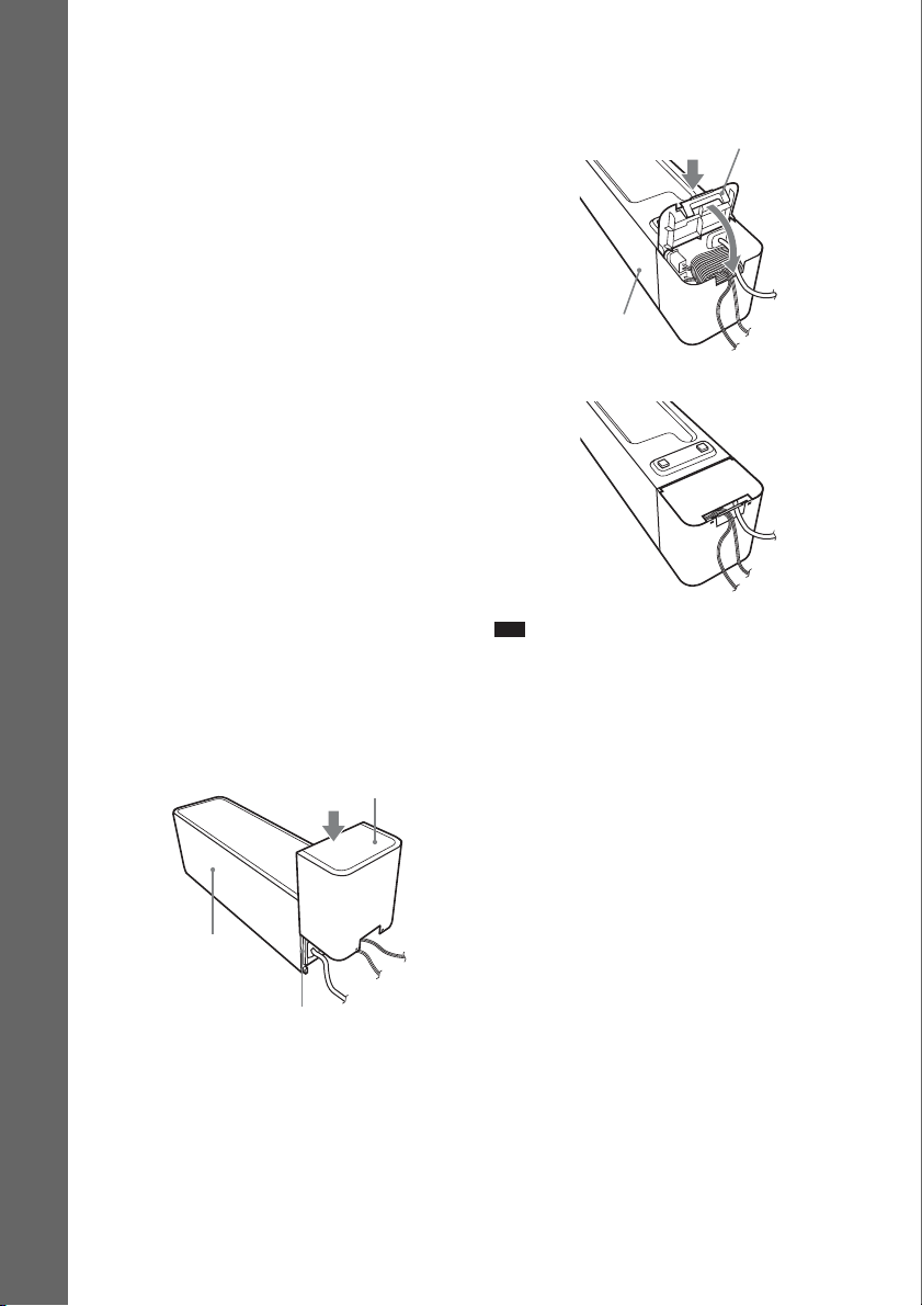
To prevent transmission from
your neighbors
To prevent the transmission from neighbors, you
can identify the unit and the surround amplifier
by performing the pairing operation. For details,
see “Identifying the unit with a specific S-AIR
sub unit (Pairing operation)” (page 102).
To use the surround amplifier for
Getting Started
the surround back speakers
You can enjoy 7.1 surround sound with the
surround back speakers by purchasing the
additional surround amplifier.
To use the surround amplifier for the surround
back speakers, connect the surround back
speakers (not supplied) to the surround
amplifier, set the SURROUND SELECTOR
switch to SURROUND BACK, and make the
S-AIR setting for the surround amplifier. For
details, see “Using an S-AIR Product”
(page 99).
To attach the cover to the
surround amplifier
After connecting and setting, you can attach the
cover to the surround amplifier for organizing
and storing excess speaker cords.
1 Attach the speaker cord cover by
sliding it down along the grooves along
the edges of the surround amplifier.
Speaker cord cover
2 Insert the tabs of the speaker cord
holder in the slots of the speaker cord
cover, and press it into place.
Speaker cord holder
Surround amplifier
m
Note
• When detaching, remove the speaker cord holder,
then remove the speaker cord cover. To remove the
speaker cord holder, slightly press the catch of the
holder and lift off. To remove the speaker cord cover,
slightly splay open the edges of the cover and slide
down.
• Do not use excessive force to store the cords.
Surround amplifier
Grooves
Push the speaker cord cover down until you
hear a click. Turn the surround amplifier
upside down, then store the cords in the
speaker cord cover.
GB
68

Step 5: Performing the Easy Setup
Follow the Steps below to make the basic
adjustments for using the system.
Displayed items vary depending on the country
model.
"/1
321
654
987
0
C/X/x/c,
HOME
1 Turn on the TV.
2 Press [/1 on the unit, and POWER on
the surround amplifier.
3 Switch the input selector on your TV so
that the signal from the system
appears on the TV screen.
The Easy Setup Display for OSD language
selection appears.
If the Easy Setup Display does not
appear
Recall the Easy Setup Display. See “To
recall the Easy Setup Display” (page 72).
4 Press X/x to select a language.
The system displays the menu and subtitles
in the selected language.
5 Press or c.
The setting message appears.
This message appears only for the fist initial
setting. It does not appear in the [Easy
Setup] in [Setup] setting.
6 Press or c.
The Setup Display for video cable selection
appears.
Easy Setup - TV connection Method
Select the video cable connecting this unit and the TV.
Component Video
Video or S Video
7 Press X/x to select the cable used to
connect the unit and TV.
Check the connection of the unit and TV
(page 57).
• When you connect the unit and TV with
the HDMI cable, select [HDMI], go to
Step 8 and set the video output resolution
for matching your TV.
• When you connect the unit and TV with
the component video cord, select
[Component Video], go to Step 8 and set
the video output resolution for matching
your TV.
• When you connect the unit and TV with
the video or S video cord, select [Video or
S Video] and go to Step 9.
Getting Started
69
GB

Note
• When you do not connect the unit and TV with
the HDMI cable, you cannot select [HDMI].
• When connecting the HDMI OUT jack and
other video output jacks at the same time, select
[Component Video].
• For details about video output resolution, see
“Video Output Resolution” (page 144).
8 Press or c.
Getting Started
The Setup Display for video output
resolution selection appears. For details, see
[Output Video Format] (page 120).
When you select [HDMI] in Step 7
Select from [Auto], [480i/576i], [480p/
576p], [720p], [1080i], or [1080p].
When connecting the HDMI OUT jack and
other video output jacks at the same time,
video signals may not output from the jacks,
other than from the HDMI OUT jack, when
[Auto] or [1080p] is selected.
When you select [Component Video] in
Step 7
Select from [480i/576i], [480p/576p],
[720p], or [1080i].
When you change the video
output resolution
A picture is displayed in the selected
resolution for about 30 seconds, then the
display asks for confirmation.
Follow the on-screen instructions and go to
the next step.
Note
• If the picture is distorted or no picture appears,
wait for about 30 seconds without pressing any
buttons. [Is this resolution OK?] appears. Select
[Cancel]. The display returns to the resolution
setting screen.
• If the selected video output resolution is
incorrect, no picture appears on the screen. In
this case, press and hold H and A on the unit
for more than 5 seconds to reset the video output
resolution to the lowest resolution. To change
the video output resolution, set [Output Video
Format] in [Video Settings] (page 119).
9 Press or c.
The Setup Display for selecting the aspect
ratio of the TV to be connected appears.
Easy Setup - TV Type
Select the screen aspect ratio to match your TV.
10 Press X/x to select the setting that
matches your TV type.
• [16:9]: If you have a wide-screen TV or a
4:3 standard TV with a wide-screen mode.
(page 119)
• [4:3]: If you have a 4:3 standard TV.
(page 119)
11 Press or c.
When you connect the unit and TV with
the HDMI cable
The Setup Display for the [Control for
HDMI] function appears. Go to Step 12.
When you do not connect the unit and
TV with the HDMI cable
The Setup Display for [BD Internet
Connection] appears. Go to Step 14.
70
GB

12 Press X/x to select the setting for the
Control for HDMI function.
Easy Setup - Control for HDMI
You can operate this unit in conjunction with a TV connected by HDMI.
Check your TV settings when using this function.
On
Select [On] to use the [Control for HDMI]
function (page 105) when connecting Sony
components that are compatible with the
Control for HDMI function.
If you do not use the [Control for HDMI]
function, select [Off].
13 Press or c.
The Setup Display for [BD Internet
Connection] appears.
14 Press X/x to select the setting for the
BD Internet connections.
You can operate the player quickly after
turning on this function.
Select [Quick Start] if you want to shorten
the startup time from the standby mode. The
default setting is [Normal].
Note
• Quick Start mode will increase electricity
consumption and activate the fan in the standby
mode.
17Press or c.
The Setup Display for [Auto Calibration]
appears.
18Connect the calibration mic to the
A.CAL MIC jack on the rear panel.
Set up the calibration mic at the ear level
using a tripod, etc. (not supplied). The front
of each speaker should face the calibration
mic, and there should be no obstruction
between the speakers and the calibration
mic.
COMPONENT VIDEO OUT
VIDEO OUT IR REMOTE
B
/
PR/
P
Y
C
C
B
R
S-VIDEOVIDEO
Y
P
B
/ CBPR / C
R
LAN(100)
SAT/CABLE
COMPONENT VIDEO IN
FRONTRFRONT
DC5V 500mA MAX
EXTERNAL
SPEAKER
CENTER WOOFER
L
A.CAL
MIC
2
C
-A
M
C
E
HDMI
OPTICAL
OUT IN
IN 1 IN 2 OUT
LR
TV
AUDIO IN
LR
AUDIO
VIDEO
SAT/CABLE IN
SAT/CABLETV
DIGITAL
IN
COAXIAL
EZW-RT10
ANTENNA
COAXIAL75
FM
A.CAL
MIC
DMPORT
ECM-AC2
DC5V
700mA
MAX
AM
Getting Started
Select [Allow] to allow Internet
connections.
If you do not allow the connections, select
[Do not allow].
15 Press or c.
The Setup Display for [Standby Mode]
appears.
16 Press X/x to select the standby mode.
Calibration mic
Ex. BDV-IT1000
71
GB

19 Press X/x to select [OK].
p
To cancel, select [Cancel].
Note
• Make sure that the headphones are not
connected to the s urround amplifier. You cannot
operate the following steps with the headphones
connected.
20 Press .
Getting Started
[Auto Calibration] starts.
The system adjusts the speaker setting
automatically.
Be quiet during the measurement.
Note
• Loud test sound is output when [Auto
Calibration] starts. You cannot turn the volume
down. Give consideration to children and
neighbors.
• Before [Auto Calibration], install the surround
amplifier in the appropriate location. If you
install the surround amplifier in an improper
location, such as another room, proper
measurement will not be obtained.
• Avoid being in the measurement area and
making noise during the measurement (which
takes about 1 minute), as it may interfere with
measurement.
• When you use the surround back speakers with
the optional surround amplifier, install the
speakers in appropriate location and turn the
surround amplifier on.
21 Confirm the conclusions of [Auto
Calibration].
The conclusions appear on the TV screen.
Press C/c to change the page. The first page
shows the distance of speakers. The second
page shows the level of speakers. If the
conclusions are ok, unplug the calibration
mic and press X/x to select [OK].
Note
• The environment of the room in which the
system is installed may affect measurements.
• If measurement fails, follow the message then
retry [Auto Calibration].
22 Press .
Easy Setup is finished. All connections and
setup operations are complete.
To quit the Easy Setup
Press HOME in any Step.
Ti
• If you change the position of the speakers, reset the
speaker settings. See “Calibrating the Appropriate
Settings Automatically” (page 108) and “Setting the
Speakers” (page 110).
• If you want to change any of the settings, see
“Settings and Adjustments” (page 117).
To recall the Easy Setup Display
1 Press HOME.
The home menu appears on the TV screen.
2 Press C/c to select [Setup].
3 Press X/x to select [Easy Setup], then
press .
4 Press C/c to select [Start], then press
.
The Easy Setup display appears.
GB
72
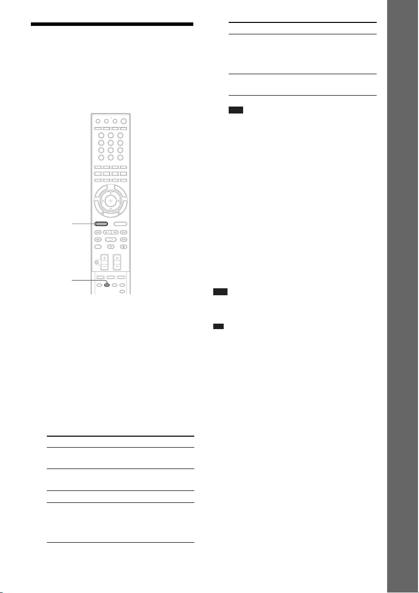
Step 6: Enjoying Sound
p
by Each Function
You can enjoy BD/DVD, TV, Set-top box/
digital satellite receiver, or VCR sound from all
the speakers in this system.
321
654
987
0
FUNCTION
DECODING
MODE
With the cover opened.
1 Press FUNCTION repeatedly until the
desired function appears in the front
panel display.
Each time you press FUNCTION, the
function changes as follows.
“BD/DVD” t “TUNER FM” t
“TUNER AM” t “TV” t “SAT/
CABLE” t “HDMI1” t “HDMI2” t
“DMPORT” t …
Function Source
“BD/DVD” Disc that is played by the
“TUNER FM”/
“TUNER AM”
“TV” TV
“SAT/CABLE” Component that is
system
FM/AM radio (page 92)
connected to the SAT/
CABLE jacks on the rear
panel (page 59)
Function Source
“HDMI1”/“HDMI2” Component that is
connected to the HDMI1
or 2 jack on the rear panel
(page 59)
“DMPORT” DIGITAL MEDIA
PORT adapter (page 98)
Note
• When you use both the TV (AUDIO IN) jacks
(analog connection) and DIGITAL IN (TV) jack
(digital connection), or SAT/CABLE IN
(AUDIO) jacks (analog connection) and
DIGITAL IN (SAT/CABLE) jacks (digital
connection) at the same time, the digital
connection takes priority.
2 Press DECODING MODE repeatedly
until the decoding mode you want
appears in the front panel display.
When you want to output the TV sound or
stereo sound of a 2 channel source from the
six speakers, select the “PRO LOGIC,”
“PLII MOVIE,” or “PLII MUSIC”
decoding mode.
For details, see page 86.
Note
• Depending on your TV, you may need to tur n off your
TV’s speaker to enjoy surround sound of the system.
Ti
• When listening to MP3 files or other compressed
music using the DIGITAL MEDIA PORT adapter,
you can enhance the sound.
Press DECODING MODE repeatedly until “A.F.D.
STD” appears in the front panel displ ay (page 86) and
set the sound mode (page 89) to “MOVIE,”
“MUSIC,” or “NEWS.”
To cancel, select other than “A.F.D. STD.”
• When using the additional surround amplifier
(optional) with the sur round back speakers (optional),
you can select “PLIIx MOVIE” and “PLIIx MUSIC”
for the decoding mode (page 86).
If distortion occurs in the sound
of a connected component
You can reduce the input level for the connected
component. For details, see [Attenuate - TV]
(page 121) and [Attenuate - SAT/CABLE]
(page 121).
Getting Started
GB
73

Playback
Playing a BD/DVD
Depending on the disc, some operations may be
different or restricted.
Refer to the operating instructions supplied with
your disc.
"/1
H
FUNCTION
x
FUNCTION VOLUME
A
Z
4 Press FUNCTION repeatedly until “BD/
DVD” appears in the front panel
display.
5 Press A.
6 Load a disc.
Place one disc on the disc tray, and then
press A.
HDMI S-AIR
Disc tray
ONE-TOUCH
PLAY
A
SCENE
SEARCH
TOP MENU
C/X/x/c,
HOME
FUNCTION
/
X
2 +/–
A/V SYNC
VOLUME +/–
321
654
987
0
"/1
Number
buttons
TIME
DISPLAY
POP UP/
MENU
OPTIONS
./>
H
m/M
x
1 Turn on your TV.
2 Switch the input selector on the TV to
this system.
3 Press "/1.
The system turns on.
When you insert a commercially available
BD-ROM or DVD VIDEO, playback
automatically starts depending on the disc.
Note
• When you play an 8 cm disc, place it on the
inner circle of the tray. Be careful that the disc is
not skewed on the inner circle of the tray.
• Do not forcibly press the disc tray closed with
your finger, as this may cause malfunction.
• Do not place more than one disc on the tray.
7 Press C/c to select [Video].
8 Press X/x to select , then press H
or .
BD Data
Video
For commercially available BD-ROM or
DVD VIDEO, playback starts.
For a BD or DVD recorded on other
equipment, the title list appears. Press X/x
to select , then press H or .
Playback starts.
9 Adjust the volume by using 2 +/– on
the remote or VOLUME +/– on the unit.
The volume level appears on the TV screen
and in the front panel display.
74
GB

Note
p
• Depending on the system status, the volume level
may not appear on the TV screen.
• When you set the [Control for HDMI] function to
[On], the TV that is connected to the system with an
HDMI cable (not supplied) can be sync-oper ated with
the system. For details, see “Using the Control for
HDMI Function for “BRAVIA” Sync” (page 105).
Ti
• You can change the speed at which the volume is
turned up and down.
To turn the volume up/down quickly, press and hold
the 2 +/– on the remote or VOLUME +/– on the
unit.
To set the volume up/down precisely, press the
2 +/– on the remote or VOLUME +/– on the unit
briefly.
To turn the system off
Press "/1 while the system is on. The system
enters standby mode.
To save power in standby mode
Press "/1 while the system is on.
To enter power saving mode, make sure that the
system is in the following status.
– [Control for HDMI] is set to [Off] (page 105).
– [S-AIR Standby] is set to [Off] (page 102).
– [Standby Mode] is set to [Normal]
(page 126).
To use the headphones
Connect the headphones to PHONES jack on the
surround amplifier. The sound of the system is
muted. For details, see page “To enjoy the sound
by using headphones” (page 67).
Other operations
To Press
Stop x
Pause X
Resume play after pause X or H
Go to the next chapter >
Go back to the
preceding chapter
. twice in a second.
When you press . once,
you can go to the beginning
of the current chapter.
To Press
Turn off the sound
temporarily
Stop play and remove
the disc
Locate a point quickly
by playing a disc in fast
forward or fast reverse
1)
(Scan)
Replay the previous
2)
scene
Briefly fast forward the
current scene
1)
Scan speeds may differ with some discs.
2)
BD/DVD VIDEO/DVD-RW/DVD-R only.
3)
BD/DVD VIDEO/DVD-RW/DVD-R/DVD+RW/
DVD+R only.
Note
• You may not be able to use the instant replay or
instant advance function with some scenes.
3)
To cancel, press it again or
2 + to adjust the sound
volume.
A
M or m while playing a
disc. Each time you press
M or m during scan,
the playback speed changes
as follows:
Playback direction
M1 (×10) t M2 (×30)
t M3 (×120)
Reverse direction
n (×1) t m1 (×10) t
m2 (×30) t m3
(×120)
When you press and hold
the button, fast forward/fast
reverse continues at the
selected speed until you
release the button.
To return to normal speed,
press H. Actual speeds
may differ with some discs.
(instant replay) dur ing
playback.
(instant advance)
during playback.
To play a restricted BD or DVD
(Parental Control)
When you play a restricted BD
Change [BD Parental Control] in [BD/DVD
Viewing Settings] (page 122).
When you play a restricted DVD
Change [DVD Parental Control] in [BD/DVD
Viewing Settings] (page 122).
Playback
GB
75

When you play a restricted BD or DVD, the
display for entering your password appears on
the screen.
Enter your four-digit password using the
number buttons, and press .
Playback starts.
To register or change the password, see
[Password] (page 123).
Available OPTIONS
1 Press OPTIONS.
The options menu appears.
2 Press X/x to select an item, then press
.
The available items differ depending on the
disc type or system situation.
To play a restricted BD-RE or BDR (Disc Lock)
When you play a BD-RE or BD-R restricted by
the Disc Lock function, the display for entering
your password appears on the screen.
1 Enter the four-digit password that has
been registered when creating the disc
using the number buttons, and press
.
2 Select a title, and press H or .
Playback starts.
One-Touch Play (for HDMI
connection only)
Press ONE-TOUCH PLAY.
The system and the connected TV turn on and
the input selector on the TV is switched to the
system, then you can enjoy the contents of a
disc.
Note
• When using the HDMI connection, there may be a
delay before the playback picture appears on the
screen, and the beginning portion of the playback
picture may not be displayed.
• To use the this function, set [Control for HDMI] to
[HDMI Settings] (page 124).
[On] in
Items Details
[Video Settings] Adjusts settings for picture
(page 81).
[Title List] Displays the title list.
[Play] Plays the title from the
point where you pressed x.
[Play from start] Plays the title from the
beginning.
[Top Menu] Displays the disc’s Top
Menu (page 78).
[Menu/Popup Menu] Displays the BD-ROM’s
Pop-up Menu or DVD’s
menu (page 78).
[Stop] Stops playback.
[Title Search] Searches for a title and
starts playback from the
beginning (page 79).
[Chapter Search] Searches for a chapter and
starts playback from the
beginning (page 79).
76
GB

Changing the angles
If various angles (multi-angles) for a scene are
recorded on a disc, you can change the viewing
angle.
Press during playback to select the
desired angle.
Note
• Depending o n the disc, you may not be able to change
the angle even if multi-angles are recorded on the
disc.
Displaying the subtitles
If subtitles are recorded on a disc, you can turn
the subtitles on/off during playback. If
multilingual subtitles are recorded on the disc,
you can change the subtitle language during
playback, or turn the subtitles on/off whenever
you want.
Press during playback to select the
desired subtitle language.
Note
• Depending o n the disc, you may not be able to change
the subtitles even if multilingual subtitles are
recorded on the disc. You also may not be able to turn
them off.
Resuming playback from the point where you stopped the disc
(Resume Play)
When you stop the disc, the system remembers
the point where you pressed x. As long as you
do not remove the disc, Resume Play will work
even if the system is set to standby mode by
pressing "/1.
1 While playing a disc, press x to stop
playback.
2 Press X/x to select , then press H
or .
The system starts playback from the point
where you stopped the disc in Step 1.
Note
• Depending on where you stop the disc, the system
may not resume playback from exactly the same
point.
• The point where you stopped playing may be cleared
when:
– you open the disc tray.
– you play another title.
– you change the settings on the system.
– you disconnect the AC power cord (mains lead).
– you remove the external memory (for BD-ROMs).
• This function may not work properly with some
discs.
Playback
To play from the beginning of the
title
Press OPTIONS to select [Play from start], then
press . Playback starts from the beginning of
the title.
77
GB

p
Using the BD’s or DVD’s menu
Enjoying BonusView/BD-Live
To display Top Menu
A BD/DVD is divided into a lot of sections,
which make up a picture or music feature. These
sections are called “titles.” When you play a BD/
DVD which contains several titles, you can
select the title you want using Top Menu.
You can also select items such as the language
for the subtitles and the language for the sound
using Top Menu.
1 Press TOP MENU.
The disc’s menu appears on the TV screen.
The contents of the menu vary depending
on the disc.
2 Press C/X/x/c or the number buttons to
select the item you want to play or
change.
3 Press .
To display Pop-up Menus
Some BD-ROMs contain Pop-up Menus that
appear without interrupting playback.
1 Press POP UP/MENU during playback.
The Pop-up Menu appears.
2 Press C/X/x/c, the color buttons, or
number buttons to select the item, and
follow the on-screen instructions.
Some BD-ROMs have bonus contents and other
data that can be downloaded to the external
memory (local storage) for enjoyment.
1 Press "/1 to turn the system off.
2 Insert the external memory (not
supplied) into the EXTERNAL slot on
the rear of the unit.
The external memory is used as the local
storage.
Make sure that the external memory is
properly inserted into the unit (page 64).
3 Press "/1 to turn the system on.
4 Insert a BD-ROM with BonusView/BD-
Live.
The operation method differs depending on
the disc. Refer to the operating instructions
supplied with the disc.
To delete data in the external
memory
You can delete unnecessary data.
1 Press HOME.
2 Press C/c to select [Video].
3 Press X/x to select [BD Data], then
press .
4 Select the disc name, then press
OPTIONS.
5 Select [Erase], then press .
6 Select [OK], then press .
The data of the selected disc will be deleted.
Note
• Depending on the BD-ROM, the disc name may not
be displayed.
Ti
• To delete all data in the external memory at once,
select [Erase All] in Step 5.
instead of OPTIONS in Step 4 to skip Step
•Press
5.
GB
78

Searching for a scene quickly
(Scene Search)
You can move quickly between scenes within
the title currently being played back.
1 Press SCENE SEARCH during
playback or in pause mode.
Playback pauses and a bar with a scene
indicator (square-shaped – indicates the
current point) appears at the bottom of the
screen.
2 Press and hold C/c or m/M to move
the scene indicator to the scene you
are searching for.
Scene indicator
Scene Search
The current point
The scene indicator on the bar is displayed
around the playing point.
3 Release the button at the point you
want to watch.
The scene at which you released the button
is displayed in pause mode.
To search for a scene again, move the scene
indicator using C/c or m/M.
4 Press SCENE SEARCH, , H, or X.
Playback starts.
To cancel Scene Search mode
Press SCENE SEARCH, , H, or X.
Playback starts from the point you pressed the
button.
Note
• The Scene Search function is available for titles
longer than 100 seconds and shorter than 100 hours.
• Depending on the disc, this function may not work.
Searching for a Title/Chapter
You can search for a chapter if the title contains
chapter marks.
1 Press OPTIONS during playback or in
pause mode.
The options menu appears.
2 Press X/x to select a search method,
then press .
• [Title Search] (for a BD-ROM/DVD
VIDEO): Searches the desired title.
• [Chapter Search]: Searches the desired
chapter.
The display for entering the number
appears.
Example: Chapter Search
Chapter :
3 Press the number buttons to enter the
number of the title or chapter.
If you make a mistake, press CLEAR, and
re-enter another number.
4 Press .
After a while, the system starts playback
from the selected number.
To cancel [Title Search]/[Chapter
Search]
Press RETURN.
Playback
79
GB

p
Displaying the playing time and play information
You can check the title information, including
the video transmission rate, etc.
Press DISPLAY during playback.
The displayed information differs depending on
the disc type and system status.
Example: When playing a BD-ROM
DDolby Digital PlusAngleAngle
English
Mbps
A The current selected angle
B Title number or name
C The currently selected audio or subtitle setting
D Available functions ( angle/ audio/
subtitle)
E Playback information
Displays Disc type/Play mode/Video codec/
Bit rate/Playing status bar/Playing time
(Remaining time*)
F Output resolution/Video frequency
* Displayed when you press TIME repeatedly.
Ti
• You can also check the playback information in the
front panel display.
• Press , , or , and you can check each
type of information.
To view the playing time and
remaining time in the front panel
display
Press TIME repeatedly.
Each time you press TIME while playing the
disc, the display changes:
1 y 2
1 Playing time of the current title
2 Remaining time of the current title
Some displayed items may disappear after a few
seconds.
GB
80

Adjusting pictures for videos
1 Press OPTIONS during playback.
The options menu appears.
2 Press X/x to select [Video Settings],
then press .
The [Video Settings] screen appears.
Video Settings
Select the item you want to change.
Picture Quality Mode
FNR
BNR
MNR
Standard
Close
Standard
3 Press X/x to select an item, then press
.
[Picture Quality Mode]
Optimizes the picture settings for different
lighting environments.
•[Standard]
• [Brighter Room]
• [Theatre Room]
[FNR]
Reduces random noise appearing in the
picture.
• [Off]
•[Auto]
[BNR]
Reduces mosaic-like block noise in the
picture.
• [Off]
•[Auto]
[MNR]
Reduces minor noise around the picture
outlines (mosquito noise).
• [Off]
•[Auto]
4 Press C/X/x/c to select or adjust the
settings, then press .
To adjust any other items, repeat steps 3 and
4.
Note
• Set the picture sett ing of your TV to [Standard] before
changing [Picture Quality Mode].
• [Video Settings] is not available when the connected
TV is set to Theatre Mode (page 106).
• Depending on the disc or the scene being played,
[FNR], [BNR], or [MNR] effects may be hard to
discern.
Playback
81
GB
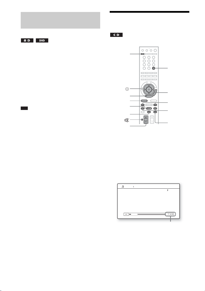
Adjusting the delay between the picture and sound
(A/V SYNC)
When the sound does not match the pictures on
the TV screen, you can adjust the delay between
the picture and sound.
1 Press A/V SYNC.
“A/V SYNC” appears in the front panel
display.
2 Press X/x to adjust the delay between
the picture and sound.
You can adjust from 0 ms to 300 ms in 25
ms increments.
Note
• Depending on the input stream, A/V SYNC may not
be effective.
Playing a CD
A
C/X/x/c,
HOME
FUNCTION
H
X
2 +/–
1 Press FUNCTION repeatedly until “BD/
DVD” appears in the front panel
display.
2 Load a CD.
The Music Player screen appears.
3 Press H.
Playback starts.
321
654
987
0
TIME
OPTIONS
./>
m/M
x
82
Music CD
Current track number and elapsed time
Stereo
4 Adjust the volume by using 2 +/–.
The volume level appears on the TV screen
and in the front panel display.
GB

To select a track
1 Press HOME.
2 Press C/c to select [Music].
Music
Music CD
3 Press .
The music list appears.
4 Press X/x to select a track, then press
H or .
The system plays the selected track.
Other operations
To Press
Stop x
Pause X
Resume play after pause X or H
Start playback from the
point where you pressed
x.
Go to the next track >
Go back to the
preceding track
Turn off the sound
temporarily
Stop play and remove
the disc
Fast reverse/fast
forwards
H
. twice in a second.
When you press . once,
you can go to the beginning
of the current track.
To cancel, press it again or
2 + to adjust the sound
volume.
A
m or M during
playback.
Available OPTIONS
1 Press OPTIONS.
The options menu appears.
2 Press X/x to select an item, then press
.
The available items differ depending on the
disc type or system situation.
Items Details
[Play] Plays the selected track.
[Play from start]
(during playback)
[Play from start]
(in stop mode)
[Stop] Stops playback.
Note
• The point where you stopped playing (resume point)
is cleared from memory when:
– You open the disc tray.
– You turn the system off.
To view the playing time and
remaining time in the front panel
display
Press TIME repeatedly.
Each time you press TIME while playing the
disc, the display changes:
1 t 2 t 3 t 4 t 1 t ...
1 Playing time of the current track
2 Remaining time of the current track
3 Playing time of the disc
4 Remaining time of the disc
Plays the current track from
the beginning.
Plays the selected track
from the beginning.
Playback
83
GB

Playing Photo Files
5 Press X/x to select , then press .
The file list or folder list appears.
1)
1)
BD-REs/BD-Rs containing JPEG image files
2)
DVD+RWs/DVD+Rs/DVD-RWs/DVD-Rs
containing JPEG image files
3)
CD-RWs/CD-Rs containing JPEG image files
C/X/x/c,
HOME
FUNCTION
X
2)
3)
321
654
987
0
DISPLAY
OPTIONS
./>
H
x
1 Press FUNCTION repeatedly until “BD/
DVD” appears in the front panel
display.
2 Load a disc that contains photo files.
3 Press HOME.
4 Press C/c to select [Photo].
Photo
Data CD
Thumbnails of files*
* Appears only when the file has thumbnail
information.
6 Press X/x to select a file or folder, then
press .
When you select a folder, press X/x to
select a file in the folder, then press .
The selected photo file is displayed.
Other operations
To Press
Play a slideshow H
Stop a slideshow x
Pause a slideshow X
Go to the next photo >
Go back to the
preceding photo
Display the file
information
.
DISPLAY
Available OPTIONS for photo files
1 Press OPTIONS.
The options menu appears.
2 Press X/x to select an item, then press
.
The available items differ depending on the
situation.
84
Items Details
[Slideshow Speed]
1)
[Stop]
GB
1)2)
Changes the slideshow
speed.
•[Fast]
•[Normal]
•[Slow]
Stops a slideshow.

Items Details
[Rotate Left]
[Rotate Right]
[ViewImage]
[Slideshow]
1)
Appears when you press OPTIONS during playback
of photo files.
2)
Appears when you press OPTIONS while the file/
folder list is displayed.
Note
• When you attempt to play the following photo files,
the mark appears on the screen and they cannot
be played.
– Photo files larger than 8,192 pixels (width or
– Photo files smaller than 15 pixels (width or height)
– Photo files exceeding 32 MB
– Photo files with extreme aspect ratios (greater than
– Photo files in Progressive JPEG format
– Photo files that have a “.jpeg” or “.jpg” extension,
– Photo files that have an extremely long name
• The following photo files cannot be played.
– Photo files recorded on BD-Rs in any format other
– Photo files recorded on BD-REs in any format
• The following photo files or folders cannot be
displayed in the file list or folder list.
– Photo files that have an extension other than
– Photo files that have an extremely long name
– Photo files in the 5th tree or lower
– 501th or more folders when the total number of
• Photo files edited on a PC may not be played.
• Thumbnail images of some photo files may not be
displayed.
• Large photo files may take some time to display or to
start a slideshow.
1)
1)
2)
2)
height)
50:1 or 1:50)
but not in JPEG format
than UDF (Universal Disk Format) 2.6
other than UDF (Universal Disk Format) 2.5
“.jpeg” or “.jpg”
folders and files in a single tree exceeds 500
Rotates the photo
counterclockwise by 90
degrees.
Rotates the photo
clockwise by 90 degrees.
Displays the selected
picture.
Starts a slideshow.
To view best quality images
If you have a Sony TV compatible with
“PhotoTV HD,” you can enjoy best quality
images by the following connection and setting.
1 Connect the unit to the TV using an
HDMI cable (not supplied).
2 Set the TV’s video setting to [VIDEO-A]
mode.
For details on [VIDEO-A], refer to the
operating instructions supplied with the
TV.
Playback
85
GB
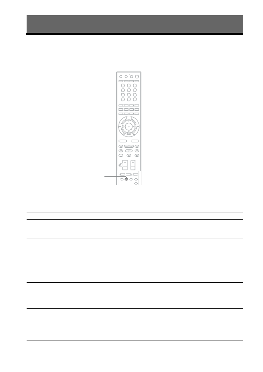
Sound Adjustment
Enjoying Surround Sound
You can enjoy surround sound simply by selecting one of the system’s pre-programmed decoding
modes. They bring exciting and powerful sound of movie theaters into your home.
321
654
987
0
DECODING
MODE
Press DECODING MODE repeatedly until the desired decoding mode appears in the front
panel display.
With the cover opened.
Display Decoding mode Effect
“A.F.D. STD” AUTO FORMAT
DIRECT
Presents sound as it was recorded/encoded.
Depending on the source, the speakers that output sound will vary.
STANDARD
“A.F.D. MULTI” AUTO FORMAT
DIRECT MULTI
2 channel source: Sound that is recorded in 2 channel (front left and
right channel) is also assigned to the surround left and right channel.
This mode outputs sound from the front left and right speakers,
surround left and right speakers, and subwoofer. The center speaker
does not output any sound.
Multi channel source: Depending on the source, speakers that output
the sound will vary.
“PRO LOGIC” Dolby Pro Logic Performs Pro Logic decoding to the input signal and simulates
surround sound from 2 channel sources.
This mode outputs sound from all the speakers and subwoofer. Sound
may not be output from all speakers depending on the source.
“PLII MOVIE” Dolby Pro Logic II
MOVIE
Performs Pro Logic II movie mode decoding to the input signal and
produces five full-band width output channels from 2 channel sources.
This setting is ideal for watching videos of overdubbed or old movies.
This mode outputs sound from all the speakers and subwoofer. Sound
may not be output from all speakers depending on the source.
GB
86

Display Decoding mode Effect
“PLII MUSIC” Dolby Pro Logic II
MUSIC
Performs Pro Logic II music mode decoding to the input signal and
produces five full-bandwidth output channels from 2 channel sources.
This setting is ideal for normal stereo sources such as a CD.
This mode outputs sound from all the speakers and subwoofer. Sound
may not be output from all speakers depending on the source.
“PLIIx MOVIE”
Dolby Pro Logic IIx
MOVIE
Performs Pro Logic IIx movie mode decoding to the input signal and
produces 7.1 output channels . This setting is ideal for watching videos
1)
of overdubbed or old movies.
Sound may not be output from all speakers depending on the source.
“PLIIx MUSIC”
1)
Dolby Pro Logic IIx
MUSIC
Performs Pro Logic IIx music mode decoding to the input signal and
produces 7.1 output channels. This setting is ideal for normal stereo
sources such as a CD.
Sound may not be output from all speakers depending on the source.
“NEO:6 CINEMA” dts NEO:6 Cinema Performs the DTS Neo:6 Cinema mode decoding to the input signal
and produces 6.1 output channels. This setting is ideal for watching
videos of overdubbed or old movies.
This mode outputs sound from all the speakers and subwoofer. Sound
may not be output from all speakers depending on the source.
“NEO:6 MUSIC” d ts NEO:6 Musi c Performs the DTS Neo:6 Music mo de decoding to the input signal and
produces 6.1 output channels. This setting is ideal for normal stereo
sources such as a CD.
This mode outputs sound from all the speakers and subwoofer. Sound
may not be output from all speakers depending on the source.
“2CH STEREO” 2 CHANNEL
STEREO
Outputs the sound from the front left and right speakers and
subwoofer. Multi channel surround formats are downmixed to 2
channels.
“HP THEATER”
2)3)
HEADPHONE
Outputs the sound as surround from headphone left and right.
THEATRE
“HP 2CH”
1)
2)
Appears only when you use the additional surround amplifier (optional) with the surround back speakers (optional)
HEADPHONE 2
CHANNEL STEREO
Outputs the sound from headphone left and right. Multi channel
surround formats are downmixed to 2 channels.
(page 67).
2)
Appears only when you connect headphones to the surround amplifier (page 67).
3)
BDV-IT1000 only. DCS technology (page 89) is used.
To turn the surround effect off
Press DECODING MODE repeatedly until “A.F.D. STD” or “2CH STEREO” appears in the front
panel display and set the sound mode (page 89) to “MOVIE” or “MUSIC.”
Note
• When you select “A.F.D. MULTI,” depending on the disc or source, the beginning of the sound may be cut off as
the optimum mode is automatically selected. To avoid cutting the sound, select “A.F.D. STD.”
• When the input signal is multi channel source, “PRO LOGIC,” “PLII MOVIE,” “PLII MUSIC,” “NEO:6
CINEMA,” and “NEO:6 MUSIC” are canceled and the multi channel source is output directly.
• When the bilingual broadcast sound is input, “PRO LOGIC,” “PLII MOVIE,” and “PLII MUSIC” are not effective.
Sound Adjustment
87
GB

• “PRO LOGIC,” “PLII MOVIE,” “PLII MUSIC,” “PLIIx MOVIE,” “PLIIx MUSIC,” “NEO:6 CINEMA,” and
p
“NEO:6 MUSIC” are canceled when you set the sound mode (page 89) to the following setting.
– “SPORTS”
– “OMNI-DIR”
– “MOVIE-D.C.S.-” (BDV-IT1000 only)
• Depending on the input stream, the decoding mode may not be effective. To activate the decoding mode, set [Fs
Limit] in [Audio Settings] (page 121) to [On].
• When changing the decoding mode while using the S-AIR receiver, sound from the S-AIR receiver may skip.
Ti
• The system memorizes the last decoding mode selected for each function mode.
Whenever you select a function such as “BD/DVD” or “TUNER FM,” the decoding mode that was last applied to
the function is automatically applied again when it is returned to. For example, if you listen to “BD/DVD” with
“PRO LOGIC” as the decoding mode, then change to another function, and then return to “BD/DVD,” “PRO
LOGIC” will be applied again.
GB
88

Selecting the Sound Mode
You can select a suitable sound mode for movies
or music.
321
654
987
0
Note
• When you connect headphones to the surround
amplifier, SOUND MODE does not work.
• Depending on the disc or source, when you select
“AUTO,” the beginning of the sound may be cut off
as the system selects the optimum mode
automatically. To avoid cutting the sound, select
other than “AUTO.”
• Depending on the input stream, the sound mode may
not be effective.
• When changing the sound mode while using the
S-AIR receiver, sound from the S-AIR receiver may
skip.
Enjoying Digital Cinema Sound
(BDV-IT1000 only)
Sound Adjustment
SOUND
MODE
Press SOUND MODE repeatedly during
playback until the desired mode appears in
the front panel display.
•“AUTO”: The system selects “MOVIE” or
“MUSIC” automatically to produce the sound
effect depending on the disc or sound stream.
• “MOVIE”: The system provides the sound for
movies.
• “MUSIC”: The system provides the sound for
music.
• “SPORTS”: The system adds reverberation for
the sports program.
• “NEWS”: The system provides the sound for
the voice program, such as news.
• “OMNI-DIR”: The system outputs the same
sound from all speakers; the same sound is
audible anywhere in the room. Multi channel
surround formats are downmixed to two
channels.
• “MOVIE-D.C.S.-”*: The system reproduces
the sound characteristics of the Sony Pictures
Entertainment “Cary Grant Theater” cinema
production studio.
* BDV-IT1000 only. DCS technology is used.
About DCS (Digital Cinema
Sound)
In collaboration with Sony Pictures
Entertainment, Sony measured the sound
environment of their studios and integrated the
data of the measurement and the Sony DSP
(Digital Signal Processor) technology to
develop “Digital Cinema Sound.” “Digital
Cinema Sound” simulates in a home theater an
ideal movie theater sound environment based on
the preference of the movie director.
About “MOVIE-D.C.S.-”
“MOVIE-D.C.S.-” is ideal for enjoying movie
software encoded with multi channel format,
such as the Dolby Digital DVD. This mode
reproduces the sound characteristics of Sony
Pictures Entertainment’s studios.
“MOVIE-D.C.S.-” consists of the following
three elements.
• Virtual Multi Dimension
The system creates five sets of virtual speakers
surrounding the listener from a single pair of
actual surround speakers.
• Screen Depth Matching
In a movie theater, sound seems to come from
inside the image reflected on the movie screen.
This element creates the same sensation in
your listening room by shifting the sound of
the front speakers “into” the screen.
• Cinema Studio Reverberation
The system reproduces the reverberations
89
GB

peculiar to a movie theater.
“MOVIE-D.C.S.-” is the integrated mode which
operates these elements simultaneously.
Note
• The virtual speaker effect may cause increased noise
in the playback signal.
• With decoding modes that use virtual speakers, you
will not be able to hear any sound coming directly
from the surround speakers.
Changing the Sound
321
654
987
0
Selecting the audio format, multilingual tracks, or channel
When the system is playing a BD/DVD VIDEO
recorded in multiple audio formats (PCM,
Dolby Digital, MPEG audio, or DTS), you can
change the audio format. If the BD/DVD
VIDEO is recorded with multilingual tracks,
you can also change the language.
With a CD, you can select the sound from the
right or left channel and listen to the sound of the
selected channel through both the right and left
speakers.
Press repeatedly during playback to
select the desired audio signal.
The audio information appears on the TV
screen.
x BD/DVD VIDEO
Depending on the BD/DVD VIDEO, the choice
of language varies.
When 4 digits are displayed, they indicate a
language code. See “Language Code List”
(page 149) to confirm which language the code
represents. When the same language is
displayed two or more times, the BD/DVD
VIDEO is recorded in multiple audio formats.
90
GB

x DVD-VR
The types of sound tracks recorded on a disc are
displayed.
Example:
• [ Stereo]
• [ Stereo (Audio1)]
• [ Stereo (Audio2)]
•[ Main]
•[ Sub]
• [ Main/Sub]
Note
• [ Stereo (Audio1)] and [ Stereo (Audio2)] do not
appear when one audio stream is recorded on the disc.
x CD
•[ Stereo]: The standard stereo sound.
• [ 1/L]: The sound of the left channel
(monaural).
• [ 2/R]: The sound of the right channel
(monaural).
Enjoying multiplex broadcast Sound
(DUAL MONO)
You can enjoy multiplex broadcast sound when
the system receives or plays the Dolby Digital
multiplex broadcast signal.
Note
• To receive the Dolby Digital signal, you need to
connect a TV or other component to the unit with an
optical or coaxial digital cord (page 57) and set the
digital output mode of the TV or other component to
Dolby Digital.
Press repeatedly until the desired
signal appears in the front panel display.
•“MAIN”: Sound of the main language will be
output.
• “SUB”: Sound of the sub language will be
output.
• “MAIN/SUB”: Mixed sound of both the main
and sub languages will be output.
Sound Adjustment
91
GB

p
p
Tuner
Listening to the Radio
You can enjoy radio sound with the system’s
speakers.
"/1
321
654
987
CLEAR
C/X/x/c,
RETURN
HOME
FUNCTION
TUNING +/–
2 +/–
TUNER
MENU
With the cover opened.
0
You can operate the tuner function by observing
the following display on the TV screen.
Current band and preset number
Number
buttons
Color
buttons (red/
green/
yellow/blue)
OPTIONS
PRESET +/–
x
DIRECT
TUNING
DISPLAY
Current station
1 Press FUNCTION repeatedly until
“TUNER FM” or “TUNER AM” appears
in the front panel display.
2 Select the radio station.
Automatic tuning
Press and hold TUNING +/– until the auto
scanning starts.
[Auto Tuning] appears on the TV screen.
Scanning stops when the system tunes in a
station.
To stop the automatic tuning manually,
press TUNING +/– or x.
“TUNED” and “ST” (for stereo program)
light up in the front panel display.
Manual tuning
Press TUNING +/– repeatedly.
3 Adjust the volume by pressing 2 +/–.
To turn off the radio
Press "/1.
Ti
• To improve reception, reorient the connected
antennas (aerials).
FM 7
MHz
88.00
SONY RADIO
Station name
Ti
• You can operate the tuner function using the tuner
menu on the front panel display. See “Operating the
tuner function using the tuner menu” (page 95).
GB
92

p
Presetting radio stations
You can preset 20 FM stations, and 10 AM
stations. Before tuning, make sure to turn down
the volume to minimum.
1 Press FUNCTION repeatedly until
“TUNER FM” or “TUNER AM” appears
in the front panel display.
2 Press and hold TUNING +/– until the
auto scanning starts.
[Auto Tuning] appears on the TV screen.
Scanning stops when the system tunes in a
station.
“TUNED” and “ST” (for stereo program)
light up in the front panel display.
3 Press OPTIONS.
The options menu appears.
4 Press X/x to select [Preset Memory],
then press .
5 Press X/x to select the preset number
you want.
6 Press .
The setting is made.
To change the preset number
Select the desired preset number by pressing
PRESET +/–, then perform the procedure from
Step 3.
Selecting the preset station
1 Press FUNCTION repeatedly until
“TUNER FM” or “TUNER AM” appears
in the front panel display.
The last received station is tuned in.
2 Press PRESET +/– repeatedly to select
the preset station.
The preset number and frequency appear on
the TV screen and front panel display.
Each time you press the button, the system
tunes in one preset station.
Ti
• You can select the preset sta tion number directly
by pressing the number buttons.
Selecting the radio station by inputting the frequencies directly
When you know the frequencies, you can select
the radio station by inputting the frequencies
directly.
1 Press FUNCTION repeatedly until
“TUNER FM” or “TUNER AM” appears
in the front panel display.
2 Press OPTIONS.
The options menu appears.
3 Press X/x to select [Direct Tuning],
then press .
4 Press the number buttons to select the
frequencies.
5 Press .
The setting is made.
If an FM program is noisy
If an FM program is noisy, you can select
monaural reception. There will be no stereo
effect, but reception will improve.
1 Press OPTIONS.
The options menu appears.
2 Press X/x to select [FM Mode], then
press .
3 Press X/x to select [Monaural].
• [Stereo]: Stereo reception.
• [Monaural]: Monaural reception.
4 Press .
The setting is made.
Tuner
GB
93

Naming preset stations
You can enter a name for preset stations. These
names (for example, “XYZ”) appear in the front
panel display when a station is selected.
Only one name can be entered for each preset
station.
When an RDS broadcast is received, the station
name appears in the front panel display.
1 Press FUNCTION repeatedly until
“TUNER FM” or “TUNER AM” appears
in the front panel display.
The last received station is tuned in.
2 Press PRESET +/– repeatedly to select
the preset station you want to create an
index name for.
3 Press OPTIONS.
The options menu appears.
4 Press X/x to select [Preset Name
Input], then press .
The display for entering characters appears.
To enter characters, see the following Steps.
To enter characters
Input FM preset name.
Clear
Clear All
Space 0
Letter Type Symbol
Cancel
Finish
1 Press the number button repeatedly to
select a character.
Example:
Press the number 3 button once to enter [D].
Press the number 3 button three times to
enter [F].
2 Press c, and enter the next character.
3 Press the blue button ([Finish]) to
finish.
You can use the following buttons to enter
characters.
Buttons Details
Red button
[Letter Type]
Green button
[A/a]
Yellow button
[Symbol]
Blue button
[Finish]
CLEAR
[Clear]/[Clear All]
RETURN
[Cancel]
C/X/x/c, • Select an input function using
Switches the keyboard between
alphabet and numbers.
Switches the keyboard between
upper case and lower case.
Displays the keyboard for
symbols.
The input is entered, and the
system returns to the previous
display.
Erases the character to the right
of the cursor.
To erase all displayed characters,
press and hold CLEAR for 2
seconds or more.
Returns to the previous display,
canceling the input.
C/X/x/c, and press .
• Enter characters as follows:
1Select a character selection
panel using C/X/x/c, and press
. 2Select a character using
C/c, and press .
Available OPTIONS for the Radio
1 Press OPTIONS.
The options menu appears.
2 Press X/x to select an item, then press
.
The available items differ depending on the
situation.
Items Details
[Preset Memory] Preset 20 FM stations, 10 AM
[Direct Tuning] Input station frequency directly.
[Preset Name
Input]
[FM Mode] Select monaural or stereo
stations.
Enter a name for a preset station.
[Preset Name Input] does not
appear when the unit is receiving
an RDS broadcast.
reception of FM programs.
94
GB

p
p
Viewing the station name or frequency in the front panel display
6 Press X/x to select the preset number
you want.
TUNED ST
When the system is set to “TUNER FM” or
“TUNER AM,” you can check the frequency
using the front panel display.
Press DISPLAY.
Each time you press DISPLAY on the remote,
the display changes as shown.
1 Station name*
2 Frequency**
* This is displayed if you have entered a name for a
preset station.
** Returns to the orig inal display when several seconds
has elapsed.
Operating the tuner function using the tuner menu
You can operate the tuner function using the
tuner menu on the front panel display.
To preset radio stations
1 Press FUNCTION repeatedly until
“TUNER FM” or “TUNER AM” appears
in the front panel display.
2 Press and hold TUNING +/– until the
auto scanning starts.
Scanning stops when the system tunes in a
station. “TUNED” and “ST” (for stereo
program) light up in the front panel display.
3 Press TUNER MENU.
4 Press X/x repeatedly until
“MEMORY?” appears in the front panel
display.
5 Press or c.
A preset number appears in the front panel
display.
TUNED ST
Ti
• You can select the preset number directly by
pressing the number buttons.
7 Press .
“COMPLETE!” appears in the front panel
display, and the station is stored.
8 Repeat Steps 2 to 7 to store other
stations.
9 Press TUNER MENU.
The system menu turns off.
To change the preset number
Select the desired preset number by pressing
PRESET +/–, then perform the procedure from
Step 3.
To listen to radio stations when
you know the frequencies
1 Press FUNCTION repeatedly until
“TUNER FM” or “TUNER AM” appears
in the front panel display.
2 Press DIRECT TUNING.
3 Press the number buttons to select the
frequencies.
4 Press .
Ti
• To improve reception, reorient the connected
antennas (aerials).
If an FM program is noisy
If an FM program is noisy, you can select
monaural reception. There will be no stereo
effect, but reception will improve.
1 Press TUNER MENU.
2 Press X/x repeatedly until “FM
MODE?” appears in the front panel
display.
TUNED ST
Tuner
3 Press or c.
GB
95

4 Press X/x to select “MONO.”
•“STEREO”: Stereo reception.
• “MONO”: Monaural reception.
5 Press .
The setting is made.
6 Press TUNER MENU.
The system menu turns off.
To name preset stations
You can enter a name for preset stations. These
names (for example, “ABC”) appear in the front
panel display when a station is selected.
Only one name can be entered for each preset
station.
When an RDS broadcast is received, the station
name appears in the front panel display.
1 Press FUNCTION repeatedly until
“TUNER FM” or “TUNER AM” appears
in the front panel display.
The last received station is tuned in.
2 Press PRESET +/– repeatedly to select
the preset station you want to create an
index name for.
3 Press TUNER MENU.
4 Press X/x repeatedly until “NAME IN?”
appears in the front panel display.
TUNED ST
7 Press .
“COMPLETE!” appears in the front panel
display, and the station name is stored.
8 Press TUNER MENU.
The system menu turns off.
5 Press or c.
6 Create a name by using C/X/x/c.
Press X/x to select a character, then press c
to move the cursor to the next position.
TUNED ST
You can input letters, numbers, and other
symbols for a radio station.
If you make a mistake
Press C/c repeatedly until the character to
be changed flashes, then press X/x to select
the desired character.
To erase the character, press C/c
repeatedly until the character to be erased
flashes, then press CLEAR.
GB
96

Using the Radio Data System (RDS)
What is the Radio Data System?
The Radio Data System (RDS) is a broadcasting
service that allows radio stations to send
additional information along with the regular
program signal. This tuner offers convenient
RDS features, such as station name display.
The station name appears on the TV screen as
well.
RDS is available only for FM stations.*
Note
• RDS may not work properly if the station you are
tuned to is not transmitting the RDS signal properly,
or if the signal strength is weak.
* Not all FM stations provide RDS service, nor do
they provide the same type of se rvices. If you are not
familiar with the RDS system, check with your local
radio stations for details on RDS services in your
area.
Receiving RDS broadcasts
Simply select a station from the FM band.
When you tune in a station that provides RDS
services, the station name* appears in the front
panel display.
* If an RDS broadcast is not received, the station
name may not appear in the front panel display.
Tuner
97
GB

p
External Audio Device
Playing the connected component on the system
Using the DIGITAL MEDIA PORT Adapter
The DIGITAL MEDIA PORT (DMPORT)
adapter (not supplied) is for enjoying sound
from a portable audio source or computer. By
connecting a DIGITAL MEDIA PORT adapter,
you can enjoy sound from the connected
component on the system.
Available DIGITAL MEDIA PORT adapters
vary in each area.
For details on connecting the DIGITAL MEDIA
PORT adapter, see “3 Connecting the other
components” (page 59).
Note
• Do not connect an adapter other than the DIGITAL
MEDIA PORT adapter.
• Do not connect or disconnect the DIGITAL MEDIA
PORT adapter to/from the unit while the system is
turned on.
• Depending on the type of DIGITAL MEDIA PORT
adapter, the images are also output (page 61).
• When you use the system and the Bluetooth Wireless
Audio Adapter (such as TDM-BT1, not supplied) at
the same time, transmission distance between the
Bluetooth transmitter and Bluetooth Wireless Audio
Adapter may be reduced. In this case, place the
Bluetooth transmitter as far as possible from the
system, or move the Bluetooth Wireless Audio
Adapter closer to the Bluetooth transmitter.
• When you use the system and the Wireless Network
Audio Adapter (such as TDM-NC1, not supplied) at
the same time, place the Wireless Network Audio
Adapter as far as possible from the system.
1 Press FUNCTION repeatedly until
“DMPORT” appears in the front panel
display.
2 Start playback of the connected
component.
The sound and images from the connected
component are played on the system or
connected TV.
For operation details, refer to the operating
instructions of the DIGITAL MEDIA
PORT adapter.
Ti
• When listening to MP3 files or other compressed
music using a portable audio source, you can enhance
the sound. Select “A.F.D. STD” for the decoding
mode (page 86) and set the sound mode (page 89) to
“MOVIE,” “MUSIC,” or “NEWS.” To cancel, select
other than “A.F.D. STD.”
• Depending on the type of DIGITAL MEDIA PORT
adapter, you may be able to operate a connected
component using either the buttons on the remote or
the unit. The following illustration shows an example
of buttons that can be used in this case.
321
654
987
0
FUNCTION
X
./>
H
x
GB
98
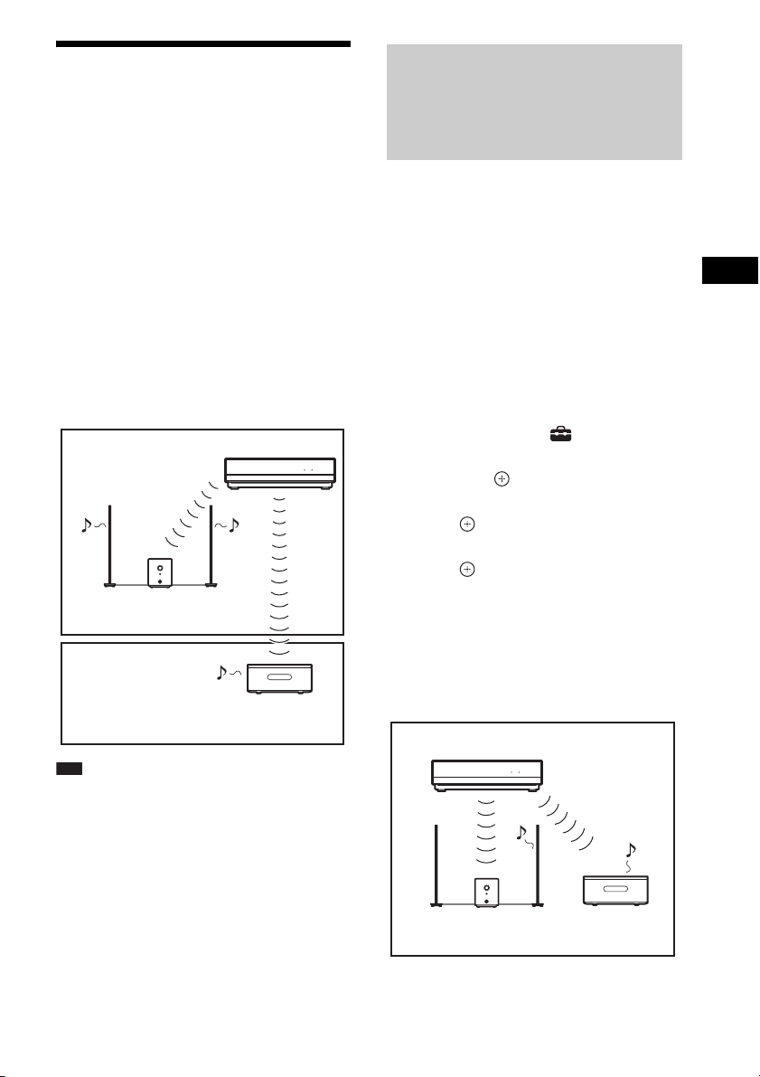
Using an S-AIR Product
The unit is compatible with the S-AIR function
(page 155), which allows sound transmission
between S-AIR products.
About S-AIR products
There are two types of S-AIR product.
• S-AIR main unit (this unit): This is for
transmitting sound. You can use up to three
S-AIR main unit. (The number of usable
S-AIR main unit depends on the use
environment.)
• S-AIR sub unit: This is for receiving sound.
– Surround amplifier: You can enjoy
surround speaker sound wirelessly.
– S-AIR receiver: You can enjoy system
sound in another room.
Room A
S-AIR sub unit
(surround amplifier)
Room B
Note
• You cannot operate this function if you do not insert
the wireless transceiver in the unit correctly
(page 63).
S-AIR main unit
S-AIR sub unit
(S-AIR receiver)
(not supplied)
HDMI S-AIR
Establishing sound transmission between the unit and S-AIR sub unit (ID setting)
For the surround amplifier
For the S-AIR receiver
Simply by matching the ID of the unit and the
S-AIR sub unit, you can establish sound
transmission.
To set the ID of the unit
1 Press "/1.
The system turns on.
2 Press HOME.
The home menu appears on the TV screen.
3 Press C/c to select [Setup].
4 Press X/x to select [System Settings],
then press .
5 Press X/x to select [S-AIR ID], then
press .
6 Press X/x to select the desired ID, then
press .
You can select any ID (A, B, or C).
The confirmation display appears, then
disappears automatically.
7 Set the S-AIR sub unit to the same ID.
Sound transmission is established as
follows (example):
S-AIR main unit
(This unit)
ID A
HDMI S-AIR
External Audio Device
ID A
S-AIR sub unit
ID A
S-AIR sub unit
99
GB

Ti
p
p
• To confirm the current ID, perform Steps 1 to 6
above. When you pair the unit with the S-AIR sub
unit (page 102), [(Pairing)] appears beside ID on the
display for selecting ID.
To set the ID of the surround
amplifier
1 Make sure that the SURROUND
SELECTOR switch of the surround
amplifier is set to SURROUND.
2 Set the S-AIR ID switch of the surround
amplifier to match the ID (A, B, or C) of
the unit.
3 Press POWER on the surround
amplifier.
When sound transmission is established,
the POWER / ON LINE indicator of the
surround amplifier turns green.
For details of the POWER / ON LINE
indicator, see “To check the transmission
status” (page 67).
Ti
• When you use the additional surround amplifier
(optional) with the surround back speakers
(optional), set the SURROUND SELECTOR
switch to SURROUND BACK.
To use multiple S-AIR main units
You can use multiple S-AIR main units by
setting a different ID for each component.
S-AIR main unit
(This unit)
HDMI S-AIR
ID A
ID A
S-AIR sub unit
ID A
S-AIR
sub unit
Other S-AIR
main unit
ID B
ID B
S-AIR sub unit
To set the ID of the S-AIR
receiver
Refer to the operating instructions of the S-AIR
receiver.
GB
100
 Loading...