

Sokkia SDM3E Operation Manual

l
I:,
CONTENTS
I FEATURES ..................................................................... 2
II SPECiFiCATIONS..:.:.................. ............ ......................... 2
1. Distance measuring....................................................... 2
2. Angle measuring. .......................................................... 4
III EXPLANATION OF PARTS .............................................. 5
IV STANDARD SET.............................................................
\' OPERATION..... .... .... ..... ............................... ........ ........ "17
1. Setting up the SDM3E ............................................ ""..17
(
~
. (1) Setting up the tripod................................................. 17
(2) Center the SDM3E by adjusting leg length .................I!!
. (3) Centering with the plumb bob ...................................20
(4) Focusing of the telescope ..........................................20
1 I
(5) Sighting'" ............ .................................................... '21
(6) Swivel
lever ..............................................................22
2. Measuring angles..... ............................................... ......23
(1) Horizontal and vertical circle reading .........................23
(2) Horizontal angle measurement ...................................25
(3) Zenith angle measurement............................;............2!!
(4) Vertical angle............................................................ 29
3. Distance measurement ..................................................30
(1) Preparation..... ..........................................................30
(2) Measuring the slope distance.....................................33
(3) Keyboard operation ................ ..................... ......... .....34
(4) Mode of measurement ..............................................42
(5) To recall data ..:.........................................................59
VI CORRECTIONS ..................... .............................. ........... '60
1. Prism constant..............................................................60
. 0 .. .". .
~WiY,;¡(t~:l"'...;.
2. Earth-curvature and refraction correction ......................60
3. Atmospheric correction .................................................61
\'I INTERNAL BATTERY No.6850-01...................................63
1. Specifications ...............................................................63
2. Handling' ..................................................................... '63
3. Precautions......................................................... ..........64
'.1
r~l
p:
r,\~
fl
"-
)
--I
VII BATTERY CHARGER No.6855-01 FOR THE INTERNAL BATTERY65
1. Specifications ................................................................65
2. Handling ................ .... ............. .......................... ........ ....65
3. Precautions................................................................. .66
IX OPTIONAL ACCESSORIES..............................................67
1. Power source system for the SDM3E ............................67
(1) 1 hour quick charger No.6855-02 .............................68
(2) 1 hour car battery charger No.6855-03 ....................69
(3) External battery converter No.6860-01 .....................71
(4) AC power adaptor No.6861-01 ..............................72
(5) Cable to cigar lighter No.6860-05 .............................73
(6) Cable to car battery No.6860-03 ..............................74
2. Diagonal eyepiece .........................................................75
X CHECKS AND ADJUSTMENTS ....................................76
1. Angle measuring function ..............................................76
(1) Plate level................................................................. 76
(2) Circular level.............................................................78
(3) Inclination of the reticle .............................................78
(4) Vertical reticle line ....................................................79
(5) Horizontal reticle line.................................................81
(6) Coincidence of the distance measuring
axis with the reticle ...................................................82
(7) Optical plummet......................... ...... ...... ......... .......... 83
2. Distance measuring function ..........................................84
(1) Self-diagnosis .........................................................84
(2) Check flow chart.......................................................
86
XI CONFIRMATION OF DISTANCE CONSTANT-...................87
XII PRECAUTIONS AND MAINTENANCE .............................88
1. Precautions ................. ............ ............. ....... .................. 88
2. Maintenance........... ........................ .............................. 89
ATMOSPHERIC CORRECTION TABLE(English) ......................90
ATMOSPHERIC CORRECTION TABLE(Metric)........................91
'.~.1~, ~
--~

Fig.
1
I. "';;,~io~ .... . -: 7~. . , ,_.
II,. _. ~~~__
~I
~
&- S;~
~J
c"
'.
~.
l':
~~
\,
,
Ii..
~ -,,,
f~'
~
'¡
¡¡
r:-:
,.
t.-
;.
~ ;
;.
i
FEATURES
.
Distance and angle measuring functions are synthesized in the
i
)
SDM3E. Accurate and rapid operation can be executed with
I
the SDM3E.
i
.
Horizontal dist~nce.height difference and coordinate are com-
l
¡:
puted and displayed by keying in angle.
.
Successive and tracking measurement as well as stake-out can
I
be selected.
¡
.
The telescope can be plunged to either direction, enabling the
¡ ,
user to observe both faces, easily.
l
.
Adjustment of light intensity is not necessa¡y.
'L
.
Incoming reflection from prism(s) is confirmed by light value
lamp or buzzing sound.
.
All the necessary information is displayed.
.
Function to output the measured data is provided.
.
Corrections for earth-curvature and refraction are carried out
automatically.
.
The SDM3E's power source is cut off two minutes after its last
operation. This saves battery capacity.
..
A convenient handle is provided for easy transportation.
II SPECIFICATIONS
1. Distance measuring
Range:
I-prism 35 to 3,900ft ( 10 to l.00m)
3-prism 35 to 5,900ft(JO to I,SOOm)
(under good atmospheric conditions)
:t (5mm + 5ppm 'D)
LED 8-digit
Maximum slope distance
6.561.66ft (1.999.999m)
Successive 0.0 1ft (J mm)
Tracking 0.1 ft (1 Omm)
Standard deviation:
Display:
Minimum count:
2
'--_. .'. .-. ~---,~ ~"---'-"'-""---_._-___-:
:;
e:
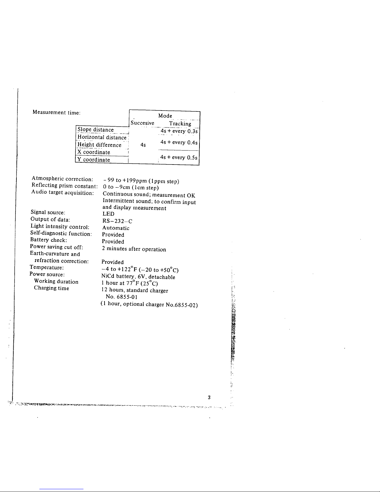
Mode
.-..
-_. ..
Succesive Tracking
.. "'-" '-'_.._, , '-
~!?IJ,e_,!i,stance_, __~
4s + every 0.3s
. --
-
Horizontal distance:
4s + every O.4s
Height difference
4s
-----.--.- -.
"
X coordinate
i
Y coordinate
I
4s + every 0.5s
,
Measurement tim
Atmospheric correction:
Reflecting prism constant:
Audio target acquisition:
Signal source:
Output of data:
Light intensity control:
Self-diagnostic function:
Battery check:
Power saving cut off:
Earth-curvature and
refraction correction:
Temperature:
Power source:
Working duration
Charging time
- 99 to +I99ppm (lppm step)
o to -9cm (Icm step)
Continuous sound; measurement OK
Intermittent sound; to confirm input
and display measurement
LED
RS-232-C
Automatic
Provided
Provided
2 minutes after operation
Provided
-4 to +I22°F (-20 to +50°C)
NiCd battery, 6V, detachable
I hour at nOF (25°C)
12 hours, standard charger
No.
6855-01
(1 hour, optional charger No.6855-02)
:~'T- .~~-~~':r;~,n~~~_,,"'r,..:_""4c:..-~=r""'''::''~..--,,.--....'t_..._...___-._----.'=-'-~______._.._:,_. __ . _.....: :_"'_:~ _'~'."' . ~..
t..
!"
!."
v.;~
~
!".
i.
3
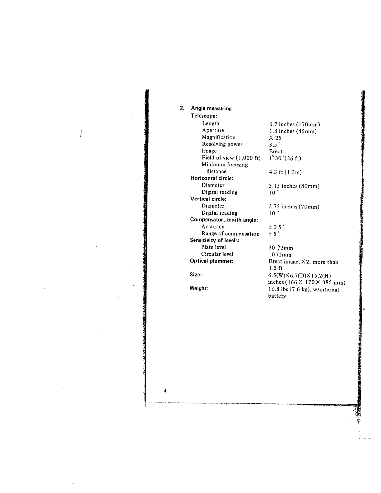
4
. -~--~ - -.--'___i-___..- ._._~_...__,
:'t;
~

II EXPLANATION OF PARTS
Refer to Fig. I. page I.
o Handle
f) Battery case cover
ê Connector
Used for data output.
Ð Instrument height mark
o Illumination slot
o Reflector
Ð Peep sight
e 00 index
When the circle positioning ring æ is turned until the 00
button on the ring comes directly below the 00 index, 00
graduation is seen through the micrometer eyepiece.
o 00 button
This shows the location of 00 graduation of the horizontal
circle.
æ Lower fine motion
CD leveling screw
æ Tribrach
æ Clamp screw of swivel
lever
Loosen the clamp screw immediately after you receive the
instrument.
æ Swivel lever
When this is given half a turn in an anticlockwise direction, it
is possible to lift the main body from the tribrach.
æ Base plate
d\ lower clamp
4D Circular level adjusting screw
The circular level adjusting screws can be turned with the
adjusting pin to center the circular level bubble.
Gi Circular level
., Circle positioning ring
When the lower clamp CD and horizontal clamp 0 are
loosened, the horizontal circle can be turned with the ring.
tI Eyepiece for optical plummet
Turn the eyepiece to focus on the reticle.
'. -~~~~~~.~:,?.~-:~:,:,,,.--
.... ......,'\...~, ......_,........_......-...._,.......--~-:~----~
5
I.
f.
"
§
)
a.
ø
ai
tZ
æ
--~
;~
:~
-,~
;i
:~I
j:
1(
'~I
'.."1
;
.J
"
j'
il
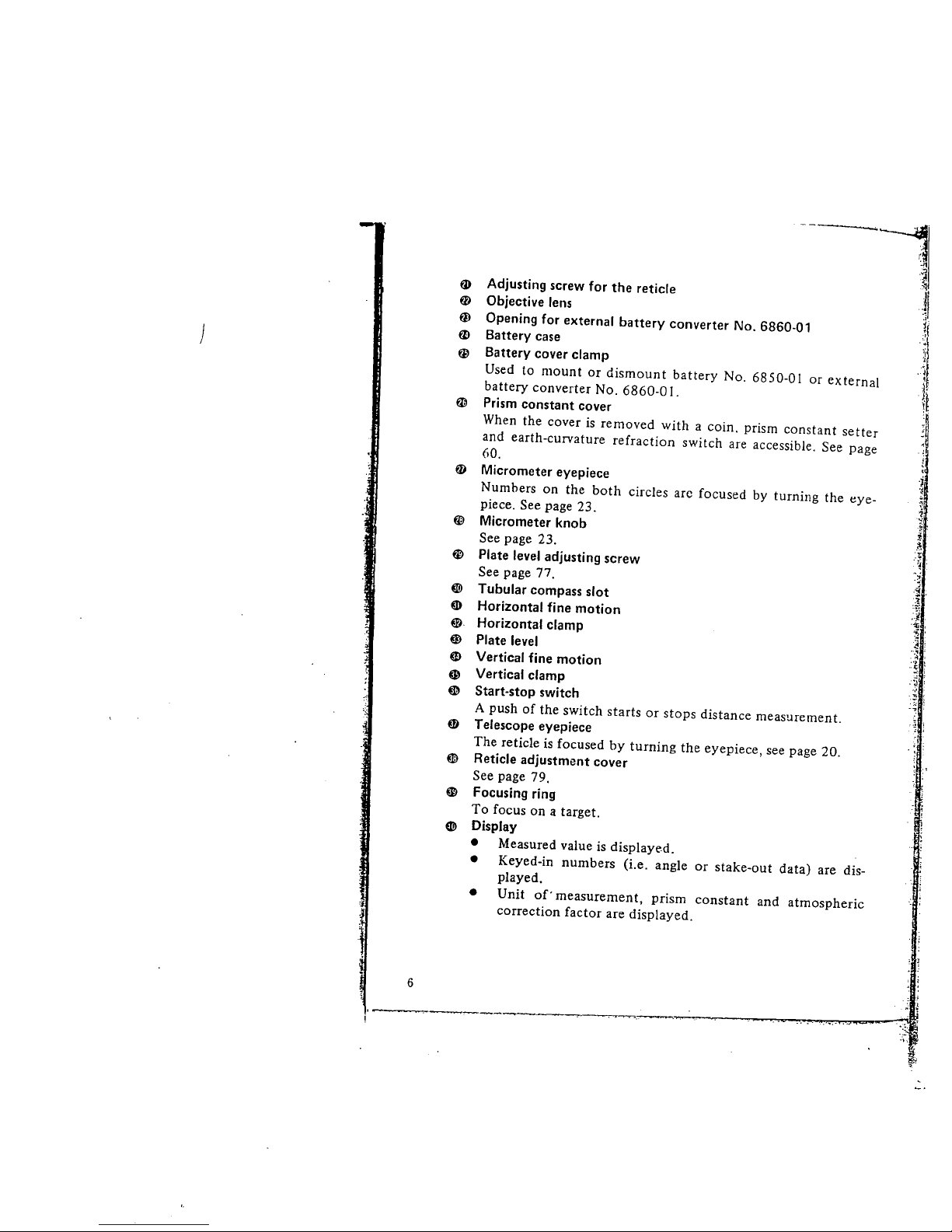
Adjusting screw for the reticle
Objective lens
Opening for external battery converter No. 6860-01
Battery case
Battery cover clamp
Used to mount or dismount battery No. 6850-01 or external
battery converter No. 6860-0 I.
Prism constant Cover
When the cover is removed with a coin. prism constant setter
and earth-curvature refraction switch are accessible. See page
60.
Micrometer eyepiece
Numbers on the both circles arc focused by turning the eye-
piece. See page 23.
Micrometer knob
See page 23.
Plate level adjusting screw
See page 77.
~ Tubular compass slot
m Horizontal fine motion
G Horizontal clamp
~ Plate level
ai Vertical fine motion
G Vertical clamp
~ Start-stop switch
A push of the switch starts or stops distance measurement.
Telescope eyepiece
The reticle is focused by turning the eyepiece, see page 20.
Reticle adjustment cover
See page 79.
Focusing ring
To focus on a target.
~ Display
· Measured value is displayed.
· Keyed-in numbers (Le. angle or stake-out data) are dis-
played.
· Unit of'
measurement, prism constant and atmospheric
correction factor are displayed.
ø
fD
-j
'I
w
~
.
~
.~
'Y
- l .
.~;
.4
.r
.~ .
i'
.~ :
. ~ ,
! :
..'5 ;
.;; :
.~ ,
:-; i
f1
m
-J !
~
~
. ¡
: ~
6
:.,
~
l.
.¡
~
~-
..
,t
l
Í'
l:
,.
,-;.
l
'"
ír
~
t.
~-.
.r
~:-.
~~~
j'
~.
f
~'
-:~
~ --=\ ~. , ..
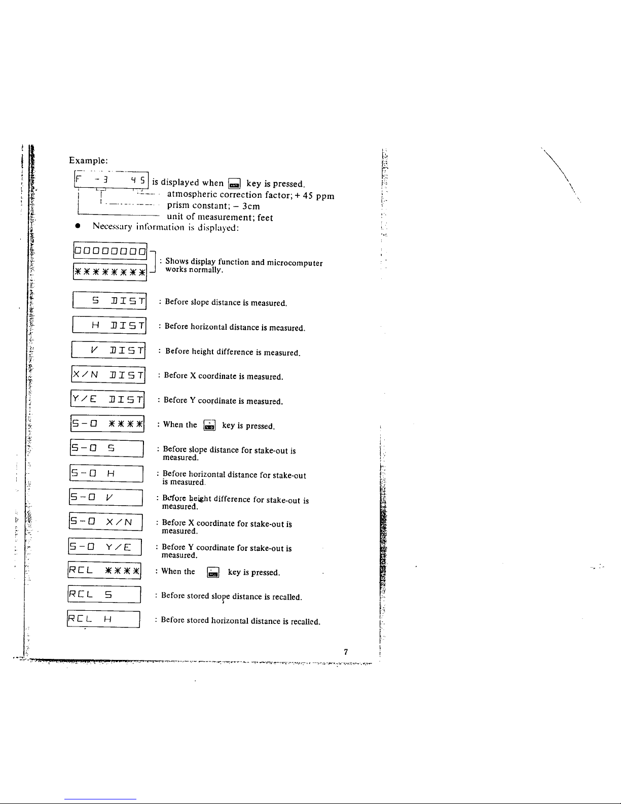
Example:
r~'
i
I
- 3 -'~ is displayed when ~ key is pressed.
L'r- L____. atinospheric correction factor; + 45 ppm
i '-.. --, prism constant; - 3cm
unit of measurement; feet
Necessary information is displayed:
.
loooooooolJ
: Shows display tunction and microcomputer
1* * * * * * * *1 works normally.
5
JJ I 5 TI
; Before slope distance is measured.
H
JJ I 5 TI ; Before horizontal distance is measured.
V
JJ I 5 TI
; Before height difference is measured.
IX/N
JJ I 5 TI
: Before X coordinate is measured.
IY/E
JJ I 5 TI ; Before Y coordinate is measured.
15-0
****1
: When the
~
key is pressed.
15-0
5
; Before slope distance for stake-out is
measured.
15-0
H
; Before horizontal distance for stake-out
is measured.
15-0
V
: Bl-ore height difference for stake-out is
measured.
15-0
X/N : Before X coordinate for stake-out is
measured.
15-0
Y/E
: Before Y coordinate for stake-out is
measured.
IRCL
**~ : When the
i;
key is pressed.
IRCL
5 : Before stored slope distance is recalled.
,
IRCL
H : Before stored horizontal distance is recalled.
"
.,~. ": '. .
",-:~i-"~_~.__ ..--,-.-:-~,.._~__.._ "''_'.~'l-...';,:-._r...1-,~~.. __':-_;'~___._~."_",.':,~,_..",,,..
b,
f:
~t
f"'~
'''''\
,
\.
f ..
ï..
i
!'
k
.::
:~t
~
j
¡:
,..
l:
¡
I'
i
7 i
)
I
I
Is-o
I
I I
1- - - - - - - -I
IRCL
IRCL
IRCL
ISI5
IllR T
III R :n
IE 02
IE 0 3
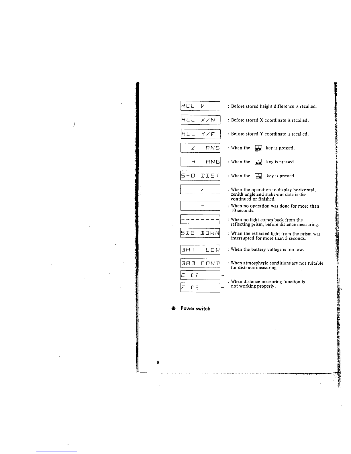
4D Power switch
8
I
X /N J
v
z
y/El
RNGI
RN51
lJ i S TI
H
lJ 0 W NI
LOWI
CON lJl
I~
IJ
: Before stored height difference is recalled.
Before stored X coordiiiate is recalled.
: Before stored Y coordinate is recalled.
: When the ~ key is pressed.
: When the ~ key is pressed.
: When the ig key is pressed.
: When the operation to display horizontal,
zenith angle and stake-out data is dis'
continued or finished.
: When no operation was done for more than
10 seconds.
: When no light comes back from the
reflecting prism, before distance measuring.
When the reflected light from the prism was
interrupted for more than 5 seconds.
: When the battery voltage is too low.
: When atmospheric conditions are not suitable
for distance measuring.
: When distance measuring function is
not working properly.
~Ý.',~.. .. ,
l!
)
l.
L
:r
; 1
i ~
, J
¡ i
1 ~l
~ I
.,.)
I
~.,
æ
..
i
~
W:
~
...~
i
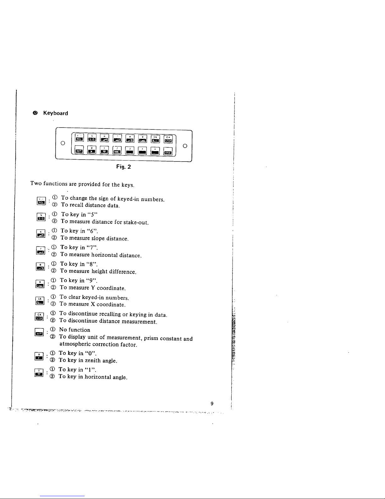
ø Keyboard
~~~~~~~~
tI l1 ~ ~ I! ~ l! Ii
0
~~~~~~~¡;
0
Fig.
2
Two functions are provided for the keys.
¡. CD To change the sign of keyed-in numbers.
ll . (2) To recall distance data.
GI . CD To key in "5"
~ . (% To measure distance for stake-out.
f' . ú)
~'ø
f'. CD
~'ø
To key in "6".
To measure slope distance.
To key in "7".
To measure horizontal distance.
~
. CD
To key in "8".
'ø
To measure height difference.
~
CD
To key in "9".
'ø
To measure Y coordinate.
~
CD
To clear keyed-in numbers.
'ø
To measure X coordinate.
fC CD To discontinue recallng or keying in data.
~ : ø To
discontinue distance measurement.
Q .CD
ll ø
No function
To display unit of measurement, prism constant and
atmospheric correction factor.
íD . CD To key in "0".
ll . ø To key in zenith angle.
f' . CD To key in "I".
~ . ø To key in horizontal angle.
.7J.-
"':~~'.l:.~;-.;-':-t~"'-;.:.:-'" ;'-',;~..~-.
"--............-...~,..---s.....ra__. ..-..-_~.n~...:-_____,~, ..__....-. .._ .. _'_.
~
~
9
)
~ .
'f
i
i
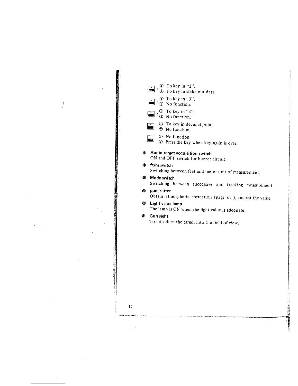
CD
~ :(í
~
¡;
~
~
CD
: (i
CD
, (i
. CD
. (i
. CD
. (i
To key in "2".
To key in stake-out data.
To key in "3".
No function.
To key in "4".
No function.
To key in decimal point.
No function.
No function,
Press the key when keying-in is over.
Q) Audio target acquisition switch
ON and OFF switch for buzzer circuit.
Gl ft/m switch
Switching between feet and meter unit of measurement.
~ Mode switch
Switching between successive and tracking measurement.
4D ppm setter
Obtain atmospheric correction (page 6 I ), and set the value.
4D Light value lamp
The lamp is ON when the light value is adequate.
EE Gun sight
To introduce the target into the field of view.
10
. - - ._.._ -, __'_'___'_"_. n ,_ ...._.___..'_._._._._...__....__._....__~
,,1
,¡
I¡~
~Ê
..~
.k:
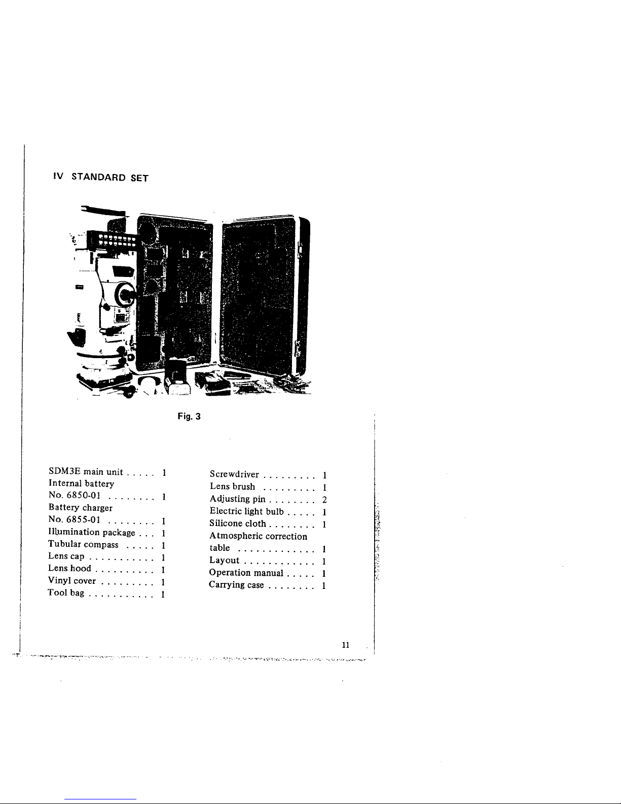
IV STANDARD SET
Fig.
3
SDM3E main unit. . . . .
Internal battery
No.
6850-01 ........
Battery charger
No.
6855-01 ........ 1
Illumination package . .. 1
Tubular compass ..... 1
Lens cap . . . . . . . . . .. 1
Lens hood . . . . . . . . " 1
Vinyl cover . . . . . . . .. 1
Tool bag. . . . . . . . . .. 1
Screwdriver. . . . . . . .. i
Lens brush ......... i
Adjusting pin . . . . . . .. 2
Electric light bulb. . . " 1
Silicone cloth. . . . . . .. 1
A tmospheric correction
table ............. 1
Layout . . . . . . . . . . .. i
Operation manual . . . " 1
Carring case . . . . . . .. i
"'~'-.-~-''l.-;----.' ..--._.;....-,-, ..._~--'-
-." w'. ,'.. ',. ".- .... -ó'':'-! ".:' :~,.. .-,. . h. ... .'.-.
'i.
't
~
,.
,,~
11
)
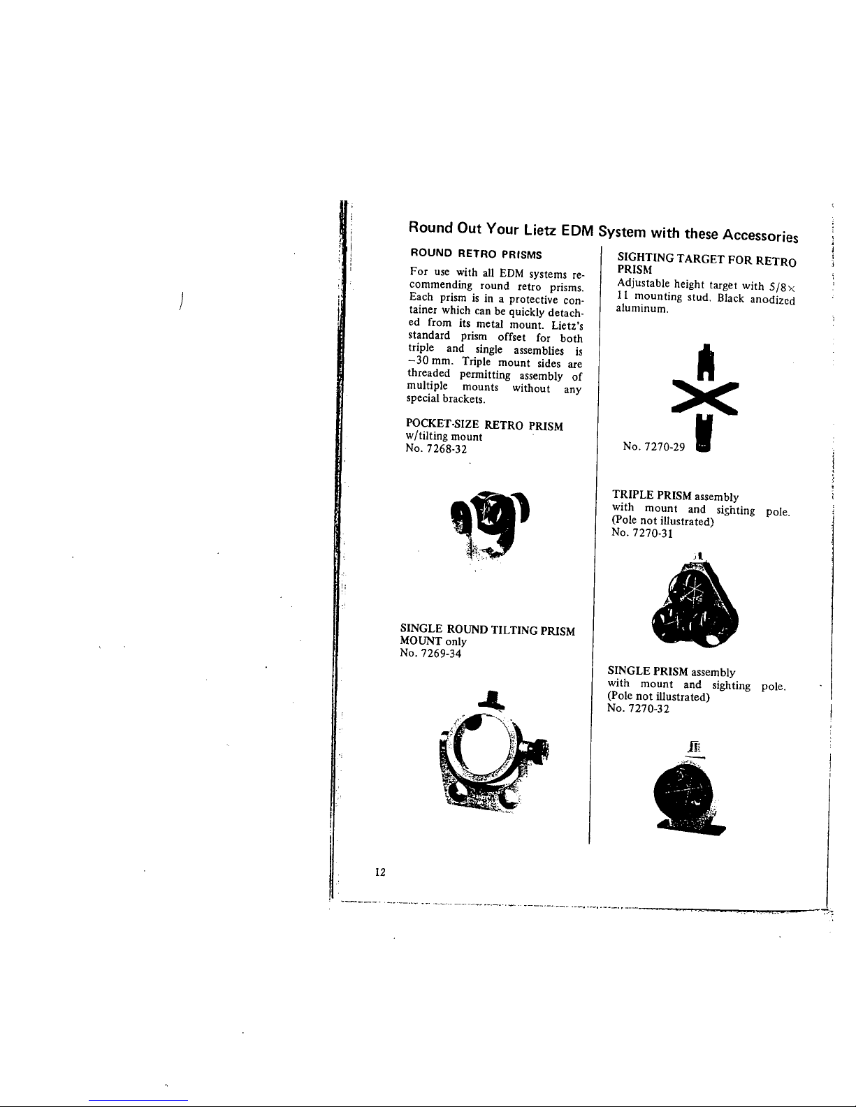
Round Out Your Lietz EDM System with these Accessories
ROUND RETRO PRISMS
For use with all EDM systems re-
commending round retro prisms.
Each prism is in a protective con.
tainer which can be quickly detach-
ed from its metal mount. Lietz's
standard prism offset for both
triple and single assem blies is
-30 mm. Triple mount sides are
threaded permitting assembly of
multiple mounts without any
special brackets.
POCKET-SIZE RETRO PRISM
w/tilting mount
No. 7268-32
_!il
~"" '.
SINGLE ROUND TILTING PRISM
MOUNT only
No. 7269-34
12
SIGHTING TARGET FOR RETRO
PRISM
Adjustable height target with 5/8 x.
i i mounting stud. Black anodized
aluminum.
*
No. 7270-29 I
TRIPLE PRISM assembly
with mount and sii;hting pole.
(Pole not ilustrated)
No.
7270-31
~ ;r ~
;~' '\
, ." "\
,,'i /'f. '
-, I ~ ..'\ ,-
, .~
SINGLE PRISM assembly
with mount and sighting pole.
(Pole not ilustrated)
No. 7270-32
1t
t.
'------ '-._'--._~ --, '-,_..~ ---~~~~-,-- ,- ---'.._.--~- ._-"-"_._,.~-
-.~
TRIPLE MOUNT only
No. 7270-33
SINGLE MOUNT only
No. 7270-34
ROUND PRISM
w/container only (shown in assem.
blies)
No. 7270-35
RETRO PRISM CARRYING
CASES
Vinyl plastic carrying case w/full
zipper for easy access and storage.
Inside padded. Exterior is bright
international orange color. Sizes for
single or triple retro prisms.
No. 7270-51 Triple retro prisms
No. 7270-52 Single retro prisms
."(
~..,., -"';-,, ;-,~,~;-,,-:~,:.,
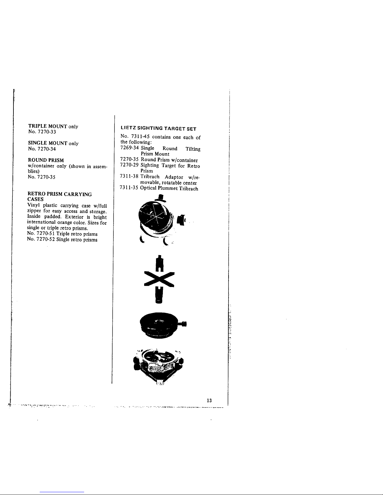
LIETZ SIGHTING TARGET SET
No. 7311-45 contains one each of
the following:
7269-34 Single Round Tilting
Prism Mount
7270-35 Round Prism w/container
7270-29 Sighting Target for Retro
Prism
7311-38 Tribrach Adaptor w/re-
movable, rotatable center
7311-35 Optical Plummet Tribrach
4.
~...
g
I
..
13
)
I
i
!
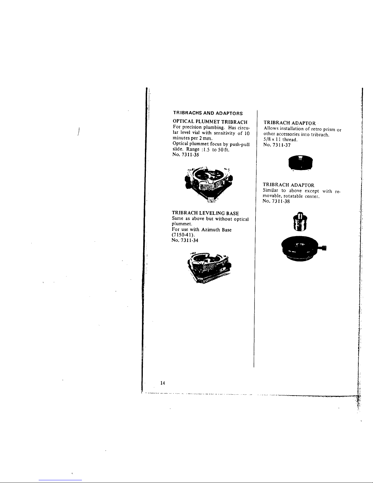
TRIBRACHS AND ADAPTORS
OPTICAL PLUMMET TRIBRACH
For precision plumbing. Has circu.
lar level vial with sensitivity of 10
minutes per 2 mm.
Optical plummet focus by push-pull
slide. Range: 1.5 to 50 fi.
No.
7311-35
TRIBRACH LEVELING BASE
Same as above but without optical
plummet.
For use with Azimuth Base
(7150-41).
No.
7311-34
~ _._~--~ _. ~ -.- - ,..., ". ,_._. .~---~-, - --'.- . -- . ,----.--- .- -- --
14
TRIBRACH ADAPTOR
Allows installation of retro prism or
other accessories into tribrach.
5/8 x 11
thread,
No.7311-37
.
TRIBRACH ADAPTOR
Similar to above except with re-
movable, rotatable center.
No. 7311.38
ti
..
i
\
i
, i
~
'~~:

TRAVERSE SET
WITH CARRYING CASE. For
precise triangulation surveys.
day or
night.
No. 7312.45 Set contains two each
of the following:
7311.35 Optical Plummet Tribrachs
7311-37 Tribrach adaptors
7312.39 Ilumination units
7312.40 Rotatable sighting targets
mounted on a base
2S
-.~f-
~;J '.
-._
Exploded
view
.
:..~ :~
.~
r=, . .',
.-,.i~...., ". .... .'
...-'... .'"
:~I
LARGE TARGET
Large target 8 'I" x I I *" attaches to
regular target (No. 73 I 2-40) to pro-
vide increased sighting range.
No.
7312-42
RANGE PLUMBING POLE
Aluminum tubing and brass fittings
with hardened steel point. Height
adjusts from 54" to 100". Upper
section mounting stud accepts single
or triple retro prisms; locking disc
prevents prism rotation. Includes
replaceable rod level (No.8071-90).
No. 7270-48
-
---
TELESCOPING RANGE
PLUMBING POLE
Ideal for EDM and traverse
work. Made of quality alumi-
num tubing with brass fittings
and hardened steel point.
Positive chuck style twist lock
permits height adjustment
from 54" to 100". Replace-
able rod level (No. 807 1-90)
and point (No. 8078-50).
Upper section has 5/8 x i i
mounting stud to accept single
or triple retro prisms.
No. 7270-46
iS
)
TR IPODS
Tripods recommended for use with
these accessories (not included in
price);
No. 7512-52 Wide Frame,
Extension Leg (wood)
No. 7536-75 Wide Frame,
Extension Leg (aluminum)
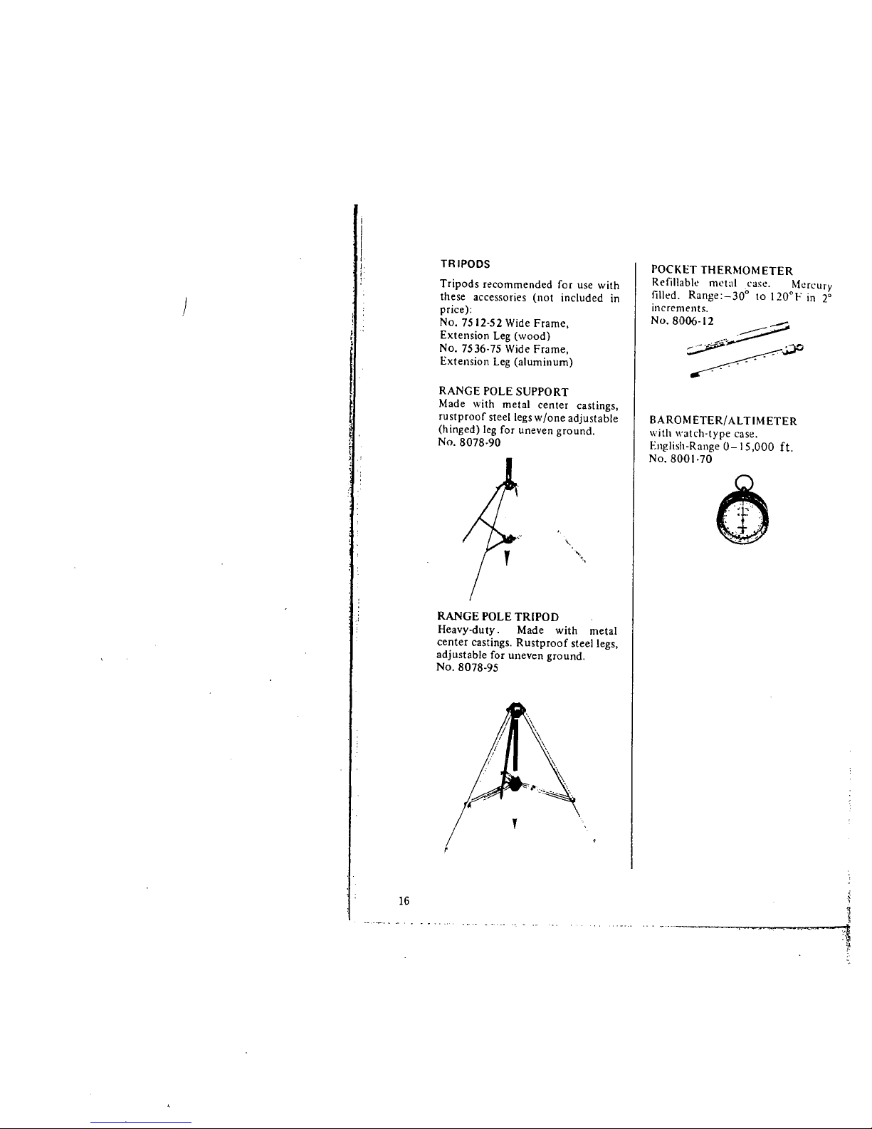
RANGE POLE SUPPORT
Made with metal center castings,
rustproof steel legs w/one adjustable
(hinged) leg for uneven ground.
No. 8078-90
"
...
"
.,
RANGE POLE TRIPOD
Heavy-duty. Made with metal
center castings. Rustproof steel legs,
adjustable for uneven ground.
No. 8078-95
,
16
POCKET THERMOMETER
Refilabk nlll.11 case. Mercury
filled. Range:-30° to 120°1- in r
increments.
NO.8006-12_:._~
~~
BAROMETER/ AL TIM ETER
with watch-type case.
English-Range 0-15,000 ft.
No.
8001.70
å)
1
,i
7~
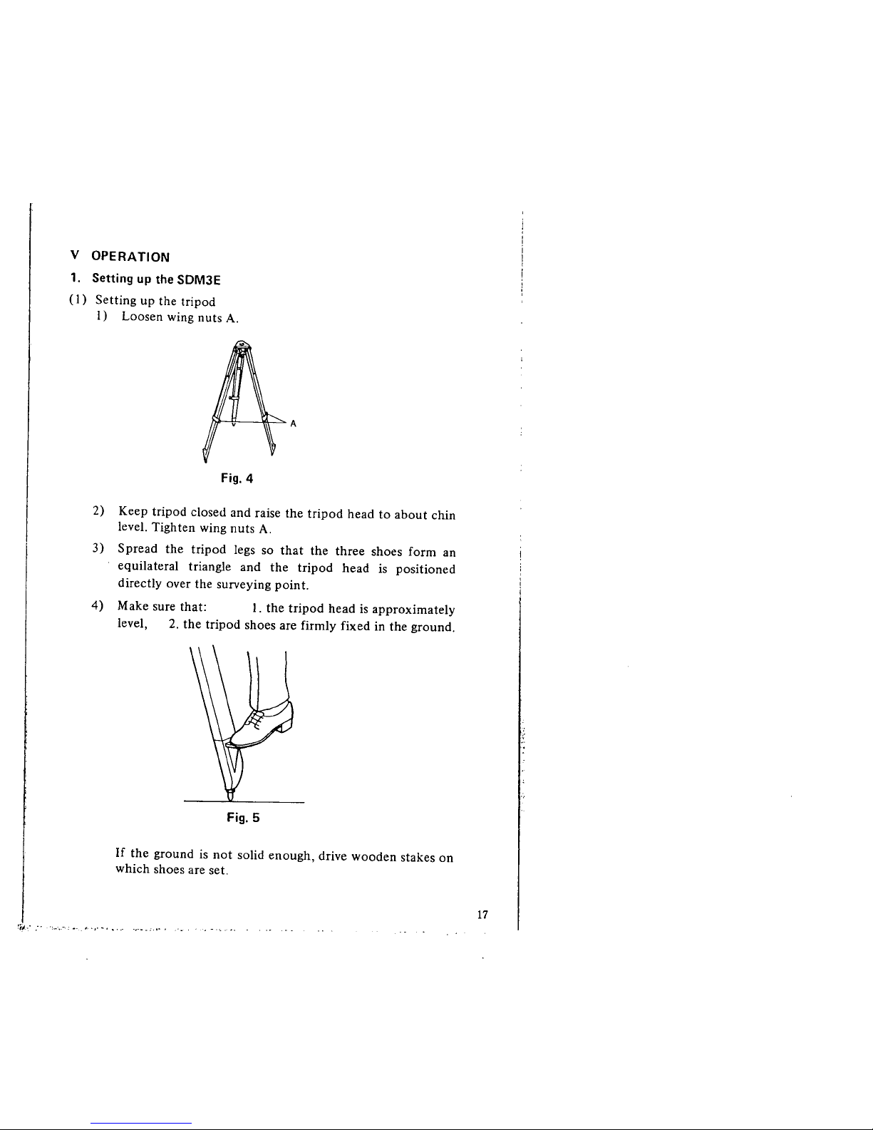
V OPERATION
1. Setting up the SDM3E
(I) Setting up the tripod
I) Loosen wing nuts A.
A
Fig.
4
2) Keep tripod closed and raise the tripod head to about chin
leveL. Tighten wing nuts A.
3) Spread the tripod legs so that the three shoes form an
equilateral triangle and the tripod head is positioned
directly over the surveying point.
4) Make sure that: i. the tripod head is approximately
level, 2. the tripod shoes are firmly fixed in the ground.
Fig.
5
If the ground is not solid enough, drive wooden stakes on
which shoes are set.
~¡;l, -." :. .'-. "', . ,. ~ . - ' ,-
17
)
ii
I;
!
,
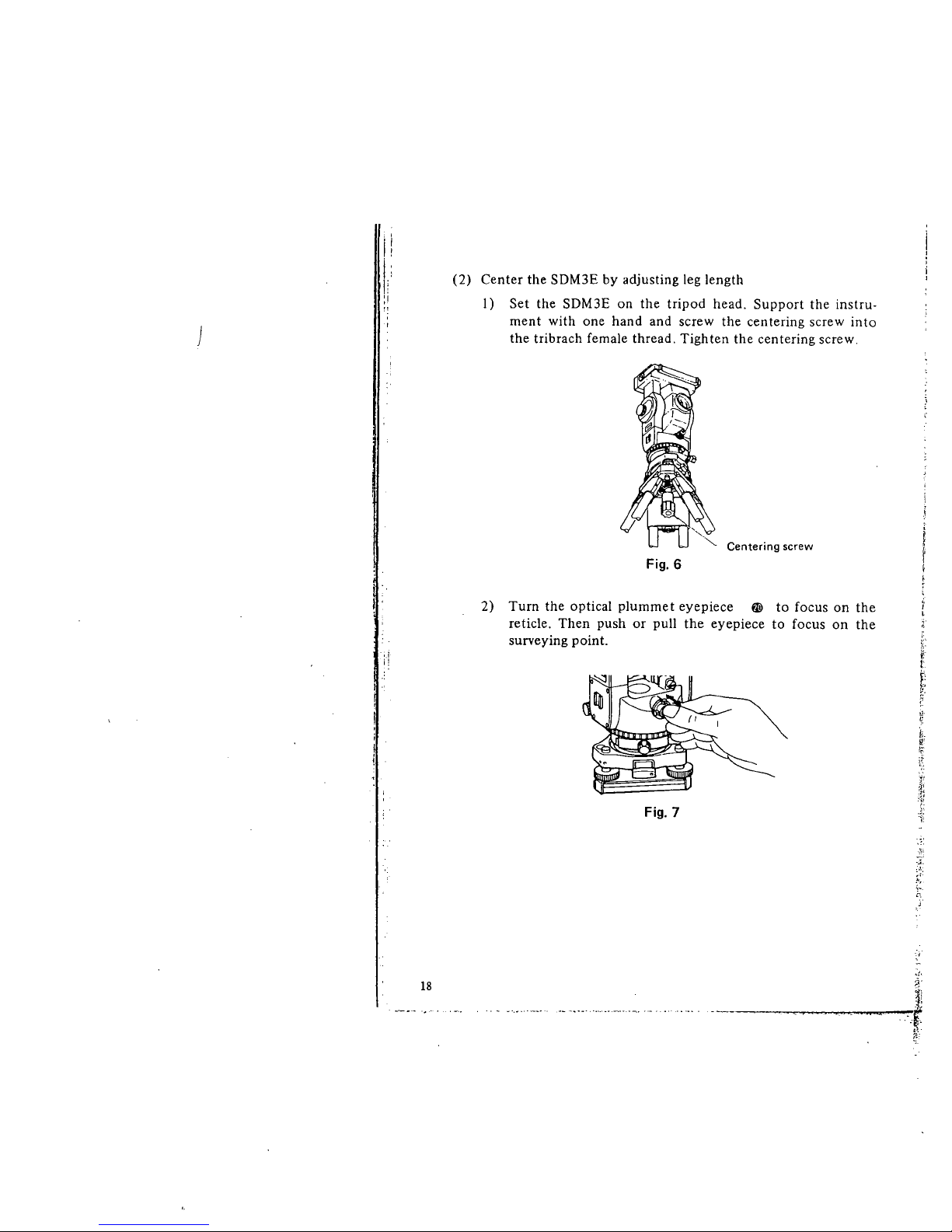
(2) Center the SDM3E by adjusting leg length
I) Set the SDM3E on the tripod head. Support the instru-
ment with one hand and screw the centering screw into
the tribrach female thread, Tighten the centering screw.
Centering screw
Fig.
6
2) Turn the optical plummet eyepiece fI to focus on the
reticle. Then push or pull the eyepiece to focus on the
surveying point.
;.
o
~;,
f,
t
~:
k
~
¡i!
.f!;
Fig.
7
Ì'
.. ~,
t'~
18
..~,
í
".
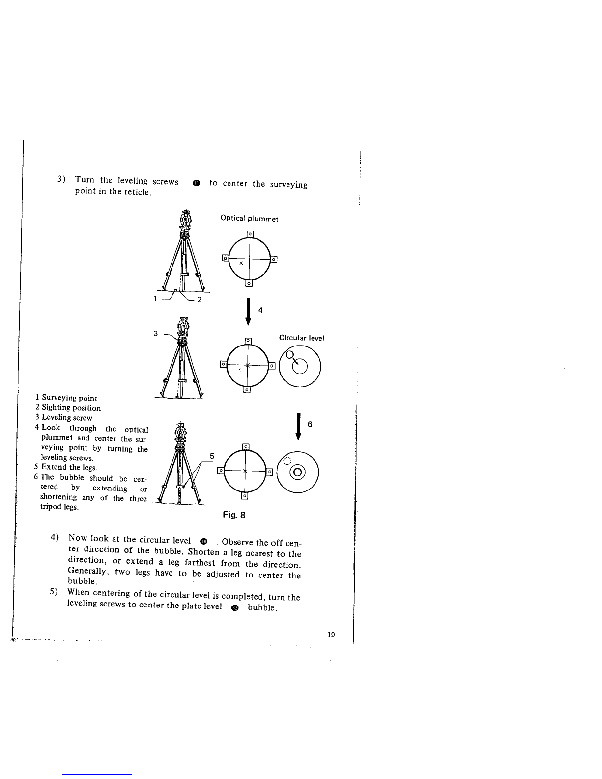
3) Turn the leveling screws
point in the reticle.
1 Surveying point
2 Sighting position
3 Leveling screw
4 Look through the optical
plummet and center the sur-
veying point by turning the
leveling screws.
5 Extend the legs.
6 The bubble should be cen-
tered by extending or
shortening any of the three
tripod legs.
3
4D to center the surveying
Optical plummet
$
l 4
$~5
l 6
$
5. . .~
Fig.
8
4) Now look at the circular level 4D _ Observe the off cen-
ter direction of the bubble. Shorten a leg nearest to the
direction, or extend a leg farthest from the direction.
Generally, two legs have to be adjusted to center the
bubble.
5) When centering of the circular level is completed, turn the
leveling screws to center the plate level CI bubble.
!l(:~'.- ~_. ..- h . -, _, .'
19
)
t, ,
6) Look through the optical plummet again. If the surveying
point is off-center. loosen the centering screw to center
the surveying point on the reticle. Tighten the centering
screw.
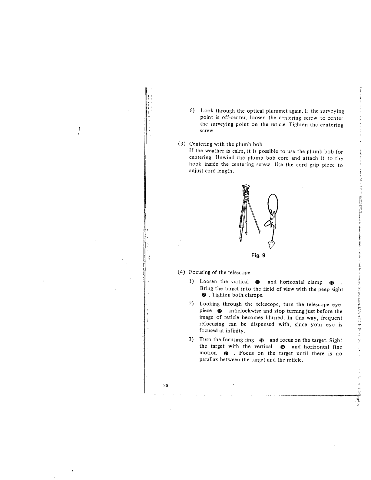
(3) Centering with the plumb bob
If the weather is calm, it is possible to use the plumb bob for
centering. Unwind the plumb bob cord and attach it to the
hook inside the centering screw. Use the cord grip piece to
adjust cord length. ,
¡.-:
l'
j:¡
,
¡!
'I
r!
:
t,
~.
f
r
~.
y
i.
t
Fig.
9
(4) Focusing of the telescope
I) Loosen the vertical ~ and horizon tal clamp K-
Bring the target into the field of view with the peep sight
f) . Tighten both clamps.
2) Looking through the telescope, turn the telescope eye-
piece ø anticlockwise and stop turning just before the
image of reticle becomes blurred. In this way, frequent
refocusing can be dispensed with, since your eye is
focused at infinity.
3) Turn the focusing ring ~ and focus on the target. Sight
the. target with the vertical CD and horizontal fine
motion ~ . Focus on the target until there is no
parallax between the target and the reticle.
~,
nì
~. ..
~¡
¡~
~:
J~ I
':"
.,
20
~.~l;
.¡;
Parallax: relative displacement of target image in respect to the
reticle when observer's head is moved somewhat
before the eyepiece.
If sighting is carried out before parallax is eliminated,
this wil introduce error in reading and will impair
your observation.
(5) Sig'iting
i) Shift the target until it coincides with the central part of
a reticle line or bisects a double line reti;e by turning the
fine motions clockwise. If the fine motion is turned too
much, give one complete anticlockwise turn, then repeat
another sighting with clockwise fine motion.
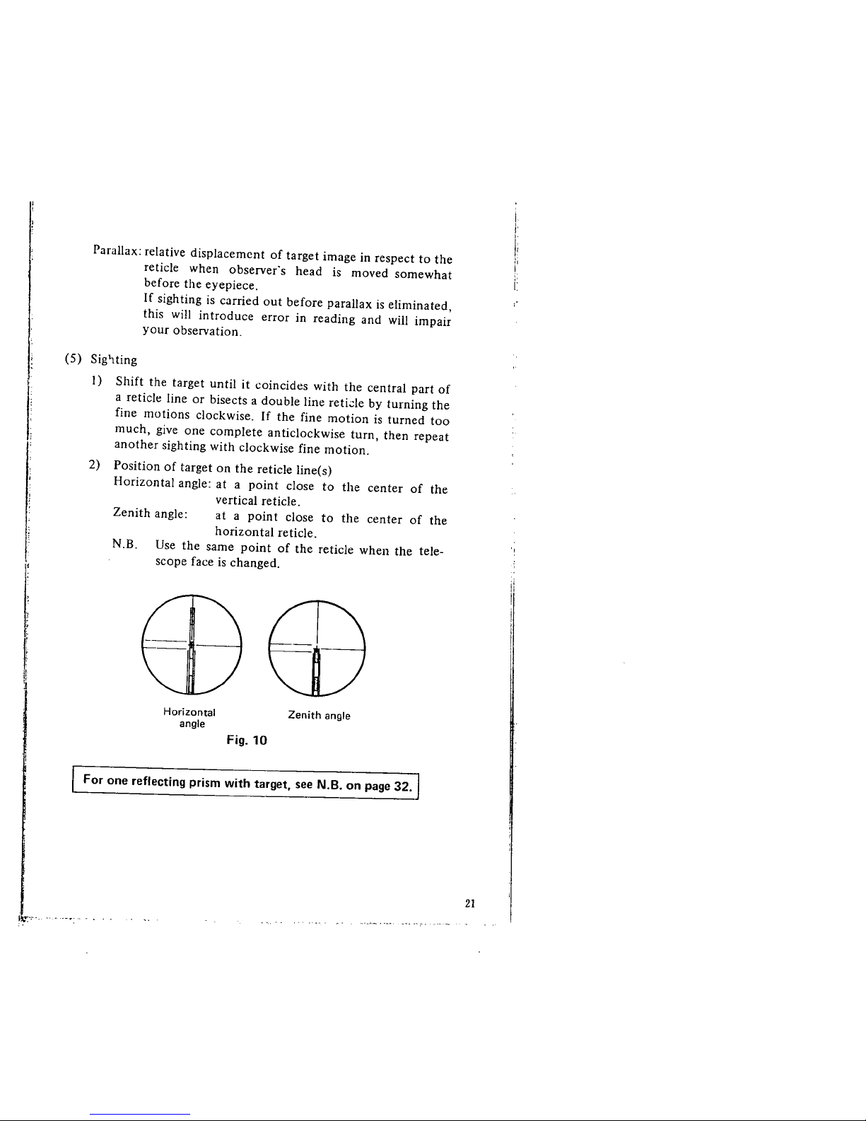
2) Position of target on the reticle line(s)
Horizontal angle: at a point close to the center of the
vertical reticle.
Zenith angle: at a point close to the center of the
horizontal reticle.
N .B. Use the same point of the reticle when the tele-
scope face is changed.
I
'i
I,
Horizontal
angle
Zenith angle
Fig,
10
For one reflecting prism with target, see N.B. on page 32.
ii:",
21
)
i
i
i I
! i
! i
I:.
I,
Ii
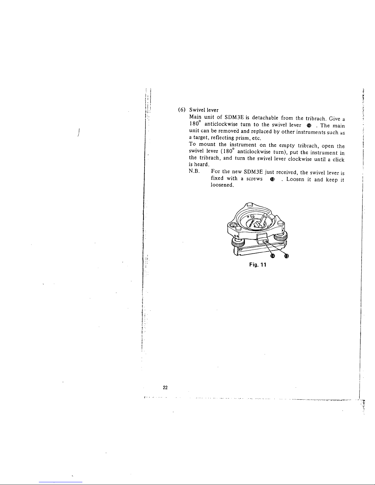
(6) Swivel lever
Main unit of SDM3E is detachable from the tribrach. Give a
1800 anticlockwise turn to the swivel lever æ . The main
unit can be removed and replaced by other instruments such "S
a target, reflecting prism, etc.
To mount the instrument on the empty tribrach, open the
swivel lever (i 800 anticlockwise turn), put the instrument in
the tribrach, and turn the swivel lever clockwise until a click
is heard.
N.B. For the new SDM3E just received, the swivel lever is
fixed with a screws 4l . Loosen it and keep it
loosened.
Fig.
11
22
, ----.-.~----:"---~--..:-.-
, ':~t
2. Measuring angles
Before measuring angles. make sure that you have carried out the
CHECKS AND ADJUSTMENTS of the SDM3E indicated on page
76.
Even for angle measurement. be sure the internal battery is
mounted.
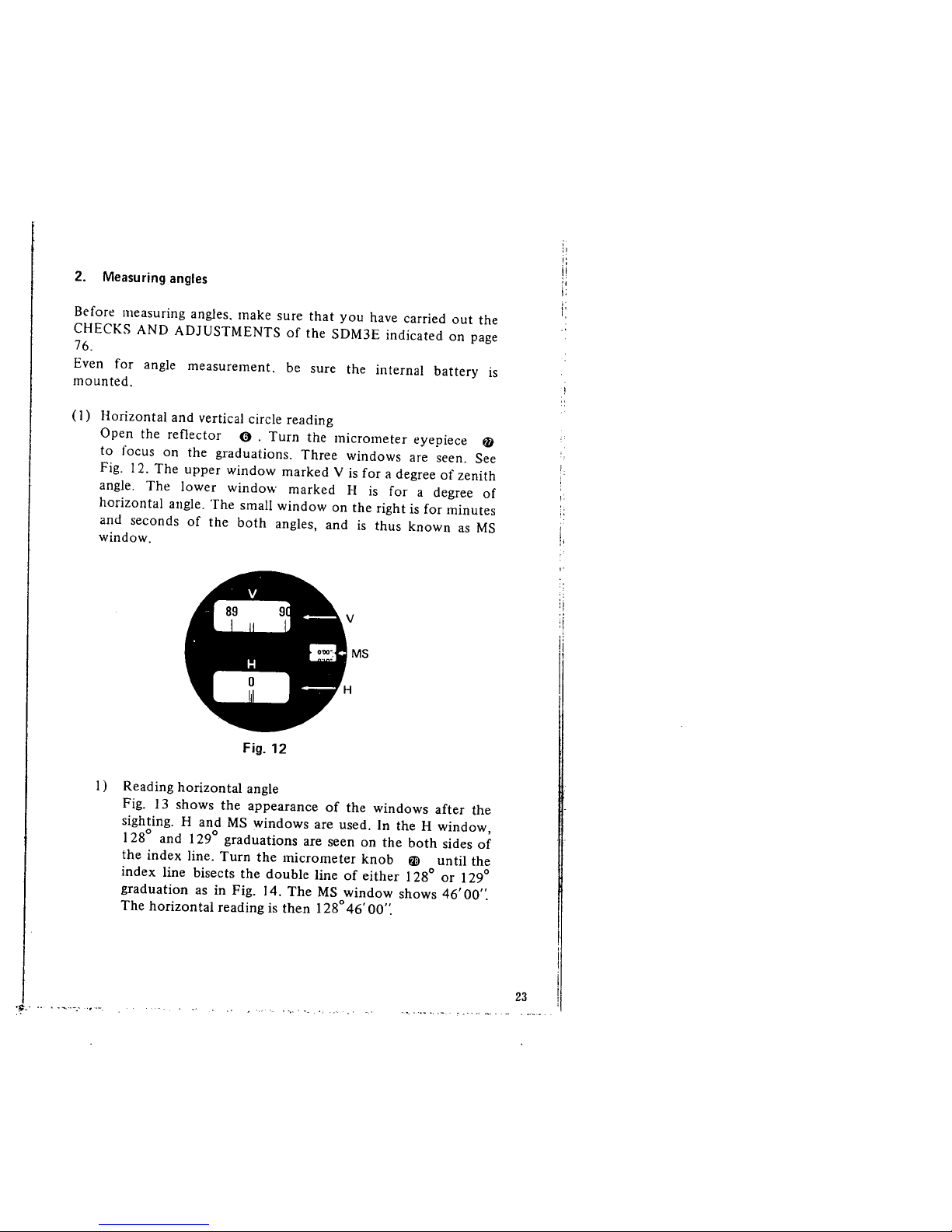
(i) Horizontal and vertical circle reading
Open the reflector 0. Turn the micrometer eyepiece fa
to focus on the graduations. Three windows are seen. See
Fig. i 2. The upper window marked V is for a degree of zenith
angle. The lower window marked H is for a degree of
horizontal angle. The small window on the right is for minutes
and seconds of the both angles, and is thus known as MS
window.
..
H ...
--
MS
Fig.
12
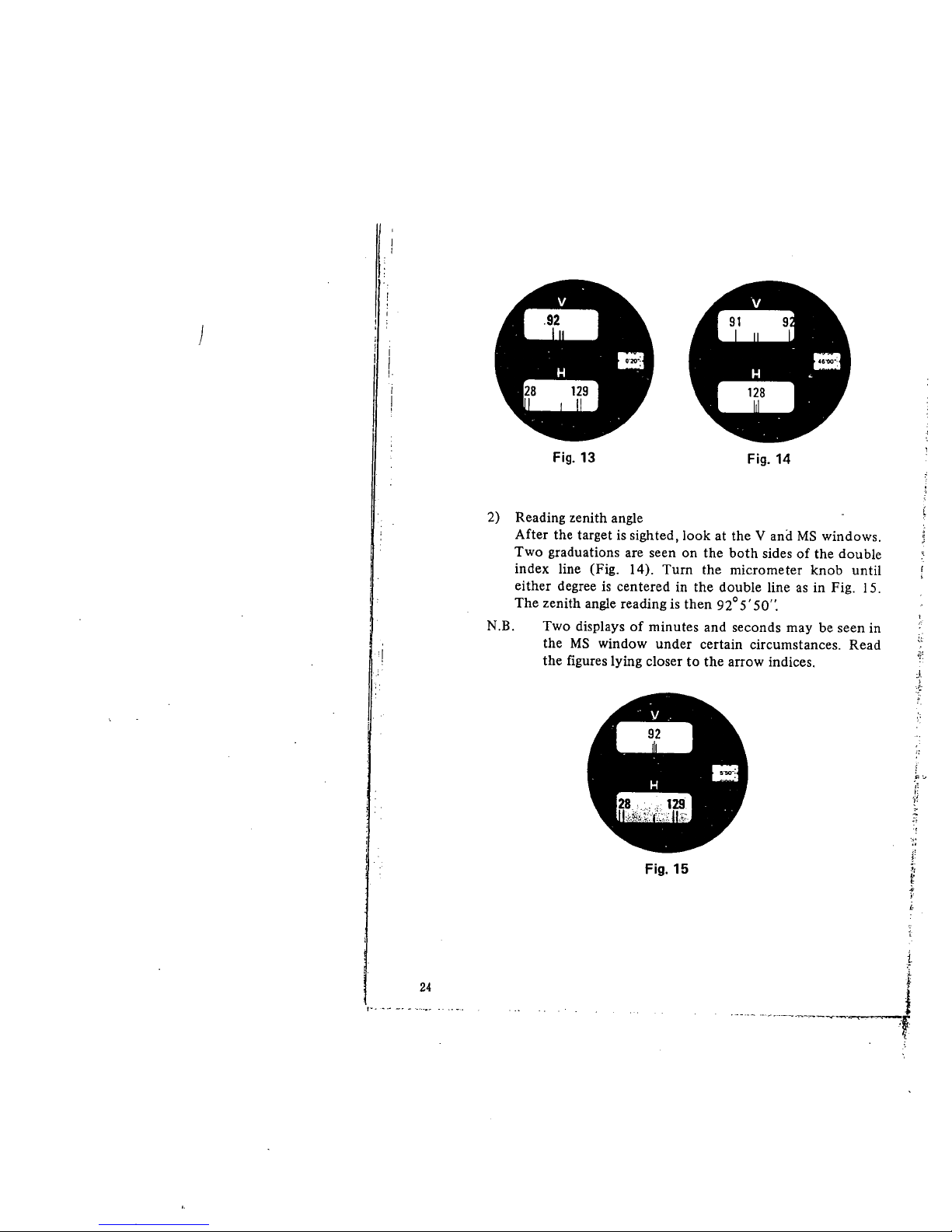
I) Reading horizontal angle
Fig. i 3 shows the appearance of the windows after the
sighting. Hand MS windows are used. In the H window,
i 28° and 129° graduations are seen on the both sides of
the index line. Turn the micrometer knob fl until the
index line bisects the double line of either 128° or 129°
graduation as in Fig. i 4. The MS window shows 46' 00".
The horizontal reading is then 128°46' 00".
:1:" ..
I
!l
:1
¡¡
Ii
23
)
!
i
'I
24
v
-
H I~
-~
Fig.
13
Fig.
14
2) Reading zenith angle
After the target is sighted. look at the V and MS windows.
Two graduations are seen on the both sides of the double
index line (Fig. 14). Turn the micrometer knob until
either degree is centered in the double line as in Fig. 15.
The zenith angle reading is then 92° 5' 50".
N.B.
Two displays of minutes and seconds may be seen in
the MS window under certain circumstances. Read
the figures lying closer to the arrow indices.
~:
ü:
...
H ..
-
J
:~
,
" c
i'!
Î:
1~
Fig.
15
~
.
t
.--._- ._.....,._-..-;-..-.-
l
t
l
'f
i
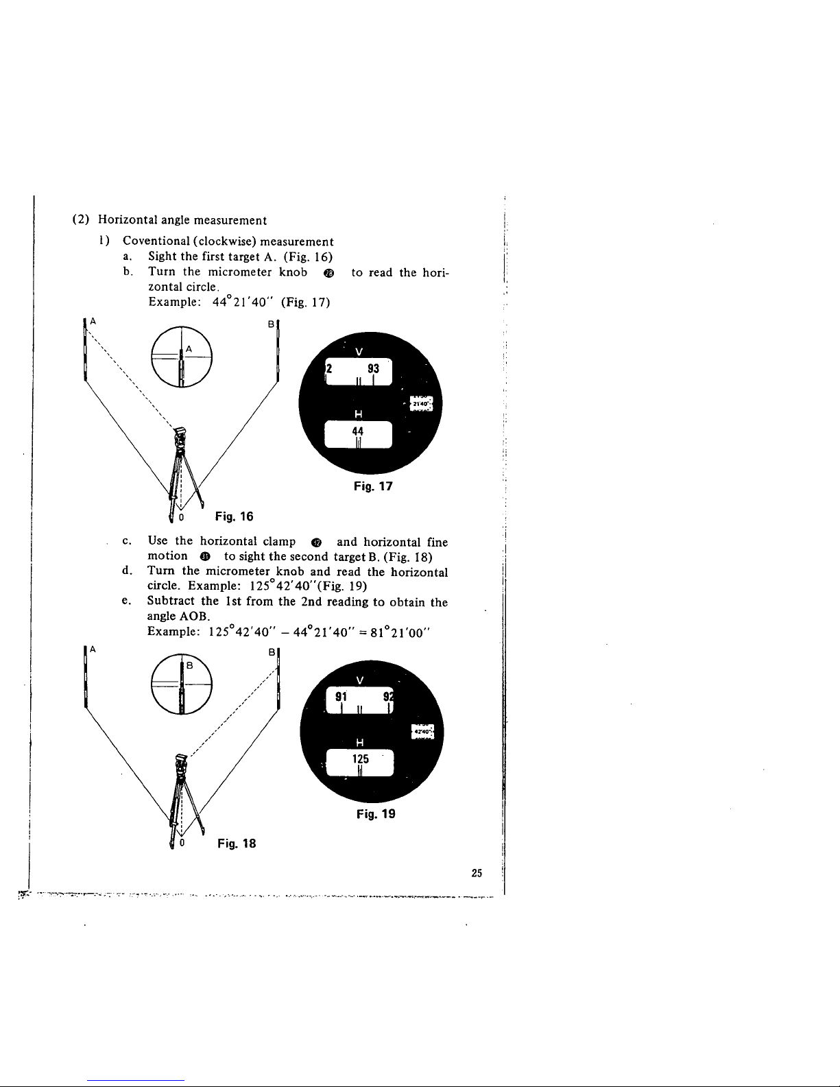
(2) Horizontal angle measurement
I) CoventionaI (clockwise) measurement
a. Sight the first target A. (Fig. 16)
b. Turn the micrometer knob ~ to read the hori-
zontal circle.
Example: 44°21'40" (Fig.
17)
A
EB
o Fig. 16
B
v
-
H .~i
--
Fig. 17
c. Use the horizontal clamp Cf and horizontal fine
motion CD to sight the second target B. (Fig. 18)
d. Turn the micrometer knob and read the horizontal
circle. Example: 125°42' 40" (Fig. 19)
e. Subtract the 1st from the 2nd reading to obtain the
angle AOB.
Example: 125°42'40" - 44°21' 40" = 81°21'00"
A
æ
o Fig. 18
~:s~ '~,--;'-:",-~_.',,-.-.. ~7--;-
B
.,..-
H ==
.,-
Fig.
19
.' ,-:. ...-. :0_ . -.-. -, ......__ . . ... ~ ".' 4... ,"-'.~..-' ,-_ __",_-,'."_' ,.. --...,.....__..:-..~_____ ._____..__
25
i i ~
)
b.
"
"
,
"
c.
'ii'
d.
d
I:
i:
';-:
'.1.
i
26
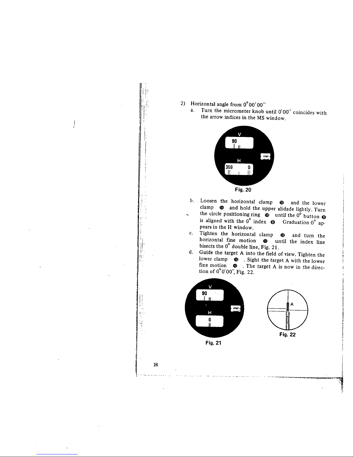
2) Honzontal angle from 0°00'00"
a. Turn the micrometer knob until 0'00" coincides with
the arrow indices in the MS window.
..
H ..
-
Fig.
20
Loosen the honzontaI clamp lD and the lower
clamp ti and hold the upper aIidade lightly. Turn
the circle positioning ring æ until the 0° button 0
is aligned with the 0° index 0 Graduation 0° ap-
pears in the H window.
Tighten the horizontal clamp lD and turn the
horizontal fine motion lD unti the index line
bisects the 0° double line, Fig. 2 i.
Guide the target A into the field of view. Tighten the
lower clamp ti . Sight the target A with the lower
fine motion d! . The target A is now in the direc-
tion of 0°0'00", Fig. 22.
v
-
H
-
II.
i ~
I
j
1
¡
i
i
t
71
"
Fig.
22
Fig.
21
 Loading...