

Sokkia RC-PR3 System Manual
SURVEYING INSTRUMENTS
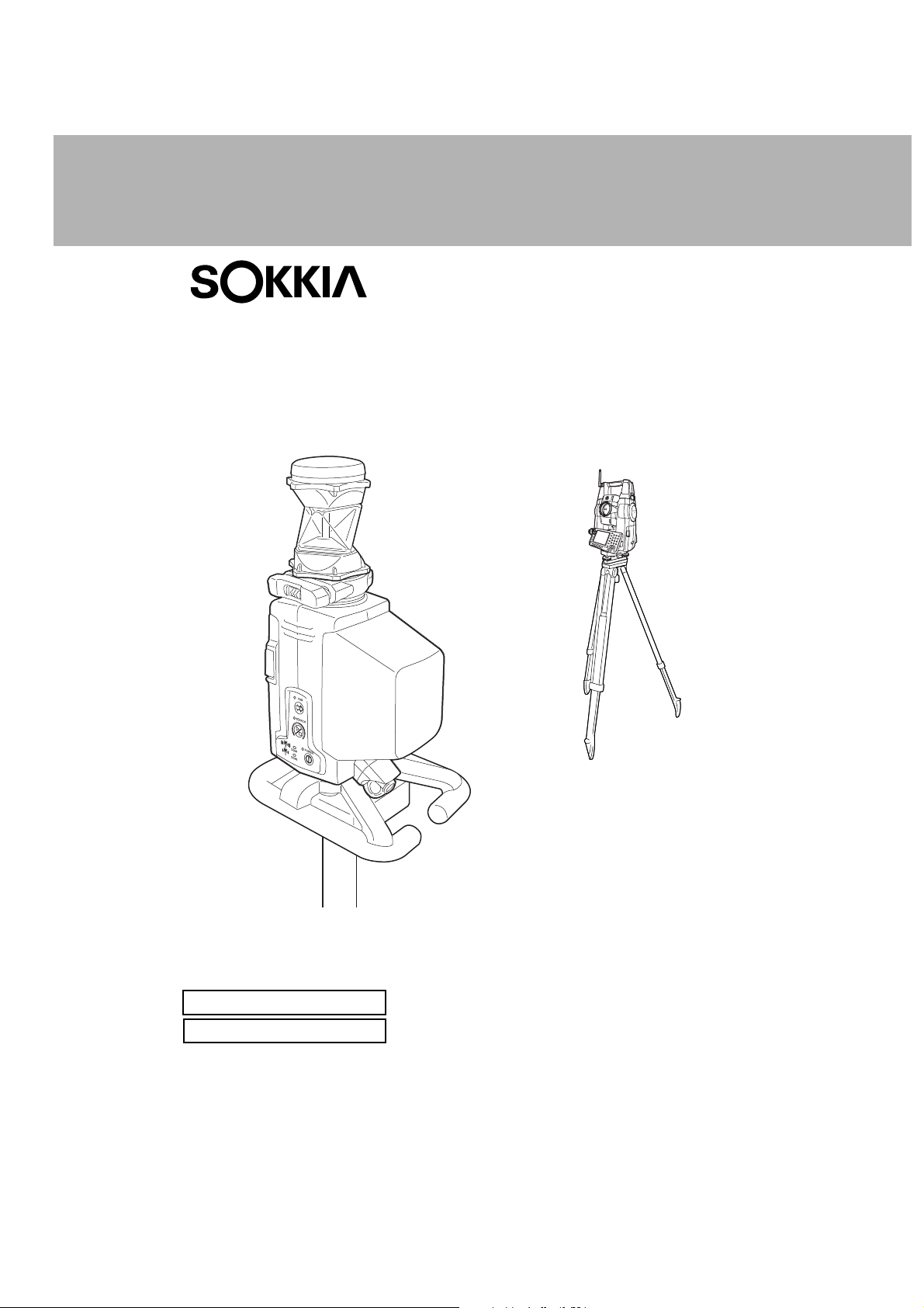
On-demand Remote Control System
RC-PR3
Class 1 Laser Product
Class 1 LED Product
SYSTEM MANUAL

:This is the mark of the Japan Surveying
Instruments Manufacturers Association.
SURVEYING INSTRUMENTS
On-demand Remote Control System
RC-PR3
Class 1 Laser Product
Class 1 LED Product
• Thank you for selecting the On-demand Remote Control System.
• Before using the instrument, please read this system manual carefully.
• The specifications and general appearance of the instrument may be altered at any
time and may differ from those appearing in brochures and this manual.
• Some of the diagrams shown in this manual may be simplified for easier
understanding.
• The On-demand Remote Control System adds remote control functions to the Series
SRX, NET05/NET1 and Series 230RM.
with the operator’s manual for your instrument
Please read this manual in conjunction
.
SYSTEM MANUAL

HOW TO READ THIS MANUAL
Symbols
The following conventions are used in this manual.
G : Indicates precautions and important items which should be read before
operations.
C : Indicates a cross-reference to refer to for additional information.
$ : Indicates supplementary explanation.
& : Indicates an explanation for a particular term or operation.
[DIST] etc. : Indicates softkeys on the total station display.
{ESC} etc. : Indicates operation keys on the total station.
I POWER etc. : Indicates RC controller LEDs.
Screens and illustrations
• Except where stated, "SRX" means Series SRX, "NET" means NET05 and NET1, "total station"
means "Series SRX/NET05/NET1/Series 230RM", and “RC controller” means the control unit for
the On-demand Remote Control System in this manual.
• The content of this system manual is mainly concerned with explaining the operation of the RC
controller. Appended functions for the SET are described in "7. APPENDED SETTINGS FOR THE
SERIES 230RM". For precautions and operating method, please read the Series 230RM Operator’s
Manual.
• Screens and illustrations used in this manual are of SRX (with RC-TS3 handle) or Series 230RM.
ii

CONTENTS
1. PRECAUTIONS FOR SAFE OPERATION ................ 1
2. PRECAUTIONS .......................................................... 3
3. LASER SAFETY INFORMATION ............................... 6
4. ON-DEMAND REMOTE CONTROL FUNCTIONS .... 7
4.1 Turning Operation Flow ..................................................... 8
4.2 Measurement Flow .......................................................... 10
5. SYSTEM CONFIGURATION .................................... 13
5.1 System Configuration of the SRX/NET ........................... 13
5.2 System Configuration of the Series 230RM .................... 14
5.3 System Configuration of the RC Controller ..................... 15
5.4 Parts of the RC Controller ............................................... 19
6. SETTINGS FOR THE SRX/NET .............................. 22
6.1 Settings for Bluetooth Communication ............................ 22
6.2 Settings for Auto Pointing and Auto Tracking ................. 24
6.3 Performing Turning from the SRX/NET ........................... 26
6.4 Turning Error ................................................................... 28
7. APPENDED SETTINGS FOR THE SERIES 230RM 29
7.1 Beam Detector ................................................................ 29
7.2 Attaching/Removing the Handle ...................................... 29
7.3 Setup for Search Before Distance Measurement ............ 30
7.4 Communication Setup ..................................................... 30
7.5 Performing Turning from the Series 230RM SFT Mode .. 31
7.6 Allocating Softkey Functions ........................................... 32
7.7 Error Messages ............................................................... 33
7.8 Turning Error ................................................................... 33
8. BASIC OPERATION ................................................. 34
8.1 Using the Battery ............................................................. 34
8.2 Button Operations ........................................................... 35
8.3 Communication Status .................................................... 37
9. RC CONTROLLER SETTINGS ................................ 38
9.1 Setting Auto Power-off .................................................... 38
9.2 Setting Communication Mode ......................................... 38
9.3 Communication Setup for the RC Controller ................... 39
9.4 Calibrating the Electronic Compass ................................ 39
10. ERROR INDICATIONS ........................................... 43
iii

CONTENTS
11. TROUBLESHOOTING ............................................. 44
12.
STANDARD EQUIPMENT AND OPTIONAL ACCESSORIES
12.1 Standard Equipment ....................................................... 46
12.2 Optional Accessories ...................................................... 46
12.3 Power Supply System ..................................................... 48
13. SPECIFICATIONS ....................................................49
14. EXPLANATION ........................................................ 53
14.1 High Accuracy with the 360° Prism.................................. 53
15. REGULATIONS ........................................................ 54
46
iv

1. PRECAUTIONS FOR SAFE OPERATION
For the safe use of the product and prevention of injury to operators and other persons as well as
prevention of property damage, items which should be observed are indicated by an exclamation point
within a triangle used with WARNING and CAUTION statements in this system manual.
The definitions of the indications are listed below. Be sure you understand them before reading the
main text.
Definition of Indication
C
C
General
C
D
G
E
WARNING
CAUTION
This symbol indicates items for which caution (hazard warnings
inclusive) is urged. Specific details are printed in or near the symbol.
J
This symbol indicates items which are prohibited.
Specific details are printed in or near the symbol.
D
This symbol indicates items which must always be performed.
Specific details are printed in or near the symbol.
I
Warning
Do not use the unit in areas exposed to high amounts of dust or ash, in areas where
there is inadequate ventilation, or near combustible materials. An explosion could occur.
Do not perform disassembly or rebuilding. Fire, electric shock, burns, or hazardous
radiation exposure could result.
When securing the instrument in the carrying case make sure that all catches, including
the side catches, are closed. Failure to do so could result in the instrument falling out
while being carried, causing injury.
Ignoring this indication and making an operation error could possibly
result in death or serious injury to the operator.
Ignoring this indication and making an operation error could possibly
result in personal injury or property damage.
Caution
C
When mounting the instrument on the pole, tighten the pole-securing knob securely.
Failure to tighten the knob properly could result in the instrument falling off the pole,
E
causing injury.
Do not carry the pole with the tip pointed at other persons. A person could be injured if
D
struck by the shoe.
1

1. PRECAUTIONS FOR SAFE OPERATION
Keep hands and feet away from the tip of the pole when fixing the pole in the ground. A
E
hand or foot stab wound could result.
Do not use the carrying case as a footstool. The case is slippery and unstable so a
D
person could slip and fall off it.
Power Supply
Warning
C
Do not short circuit. Heat or ignition could result.
D
Do not disassemble, rebuild, mutilate, incinerate, heat or short circuit the battery and
G
charger. Fire, electric shock, burns or an explosion could result.
Do not use batteries or the battery charger if wet. Resultant shorting could lead to fire or
D
burns.
Use only the specified battery charger to recharge batteries. Other chargers may be of
E
different voltage rating or polarity, causing sparking which could lead to fire or burns.
Do not heat or throw batteries into fire. An explosion could occur, resulting in injury.
H
Do not use the battery for any other purpose. Fire or burns caused by ignition could
D
result.
To prevent shorting of the battery in storage, apply insulating tape or equivalent to the
E
terminals. Otherwise shorting could occur resulting in fire or burns.
Caution
C
Do not touch liquid leaking from batteries. Harmful chemicals could cause burns or
F
blisters.
Bluetooth wireless technology
Warning
C
Do not use within the vicinity of hospitals. Malfunction of medical equipment could
D
result.
Use the instrument at a distance of at least 22 cm from anyone with a cardiac
pacemaker. Otherwise, the pacemaker may be adversely affected by the
D
electromagnetic waves produced and cease to operate as normal.
Do not use onboard aircraft. The aircraft instrumentation may malfunction as a result.
D
Do not use within the vicinity of automatic doors, fire alarms and other devices with
automatic controls as the electromagnetic waves produced may adversely affect
D
operation resulting in an accident.
2

2. PRECAUTIONS
Precautions
• Protect instruments from heavy shocks or vibration.
• Never touch the RC controller laser projection port or the total station beam detector. The ability of
the system to perform Turning may be adversely affected.
• Turn the power OFF before removing the battery from the RC controller.
• Remove the battery when the RC controller is not used for long periods.
Maintenance
• Wipe the RC controller laser projection port and total station beam detector with the wiping cloth
(total station accessory).
• To clean the RC controller, lightly moisten a soft cloth in a mild detergent solution. Wring out excess
water until the cloth is slightly damp, then carefully wipe the surface of the unit. Do not use any
organic solvents or alkaline cleaning solutions.
• Store the instrument in a dry room where the temperature remains fairly constant.
• Check the RC controller for proper adjustment periodically to maintain the instrument accuracy.
Precautions concerning water and dust resistance
The RC controller conforms to IP55 specifications for waterproofing and dust resistance when the
battery cover is closed and connector caps are attached correctly.
• Make sure that moisture or dust particles do not come in contact with the terminal or connectors.
Operating the instrument with moisture or dust on the terminal or connectors may cause damage to
the instrument.
• Be sure to correctly attach the connector caps to protect the RC controller from moisture and dust
particles when the connector is not in use.
• Make sure that the inside of the carrying case and the instrument are dry before closing the case. If
moisture is trapped inside the case, it may cause the instrument to rust.
Charging the battery
• The battery (BDC46B) was not charged at the factory. Charge the battery fully before using.
Precautions concerning Bluetooth wireless technology
• Use of this technology must be authorized according to telecommunications regulations of the
country where the instrument is being used. Contact your Sokkia agent in advance.
C "15. REGULATIONS"
• Sokkia is not liable for the content of any transmission nor any content related thereto. When
communicating important data, run tests beforehand to ascertain that communication is operating
normally.
• Do not divulge the content of any transmission to any third party.
Radio interference when using Bluetooth technology
Bluetooth communication with the RC controller uses the 2.4 GHz frequency band. This is the same
band used by the devices described below.
•Industrial, scientific, and medical (ISM) equipment such as microwaves and pacemakers
• portable premises radio equipment (license required) used in factory production lines etc.
• portable specified low-power radio equipment (license-exempt)
3

2. PRECAUTIONS
•IEEE802.11b/IEEE802.11g standard wireless LAN devices
The above devices use the same frequency band as Bluetooth communications. As a result, using the
RC controller within proximity to the above devices may result in interference causing communication
failure or reduction of transmission speed.
Although a radio station license is not required for this instrument, bear in mind the following points
when using Bluetooth technology for communication.
● Regarding portable premises radio equipment and portable specified low-power radio
equipment:
• Before starting transmission, check that operation will not take place within the vicinity of portable
premises radio equipment or specified low-power radio equipment.
• In the case that the instrument causes radio interference with portable premises radio equipment,
terminate the connection immediately and take measures to prevent further interference (e.g.
connect using an interface cable).
• In the case that the instrument causes radio interference with portable specified low-power radio
equipment, contact your Sokkia agent.
● When using the RC controller in proximity to IEEE802.11b or IEEE802.11g standard wireless
LAN devices, turn off all devices not being used.
• Interference may result, causing transmission speed to slow or even disrupting the connection
completely. Turn off all devices not being used.
● Do not use the RC controller in proximity to microwaves.
• Microwave ovens can cause significant interference resulting in communication failure. Perform
communication at a distance of 3m or more from microwave ovens.
● Refrain from using the RC controller in proximity to televisions and radios.
• Televisions and radios use a different frequency band to Bluetooth communications.
However, even if the RC controller is used within proximity to the above equipment with no adverse
effects with regard to Bluetooth communication, moving a Bluetooth compatible device (including
the RC controller) closer to said equipment may result in electronic noise in sound or images,
adversely affecting the performance of televisions and radios.
Precautions regarding transmission
● For best results
• When using in conjunction with a total station, perform communication within a line-of-sight distance
of approximately 300m. The usable range becomes shorter when obstacles block the line of sight,
or devices other than total stations, such as PDAs or computers, are used. Wood, glass and plastic
will not imped
e communication but the usable range becomes shorter. Moreover, wood, glass
and plastic containing metal frames, plates, foil and other heat shielding elements as well as
coatings containing metallic powders may adversely affect Bluetooth communication and
concrete, reinforced concrete, and metal will render it impossible.
• Use a vinyl or plastic cover to protect the instrument from rain and moisture. Metallic materials
should not be used.
• The direction of the Bluetooth antenna can have adverse effects upon usable range. For best
results make sure that the antennas of both the RC controller and the companion device are
pointing towards one another.
4

2. PRECAUTIONS
● Reduced range due to atmospheric conditions
The radio waves used by the RC controller may be absorbed or scattered by rain, fog, and moisture
from the human body with the limit of usable range becoming lower as a result. Similarly, usable range
may also shorten when performing communication in wooded areas. Moreover, as wireless devices
lose signal strength when close to the ground, perform communication at as high a position as
possible.
G
• Sokkia cannot guarantee that all Bluetooth devices are compatible with the On-demand Remote
Control System.
5
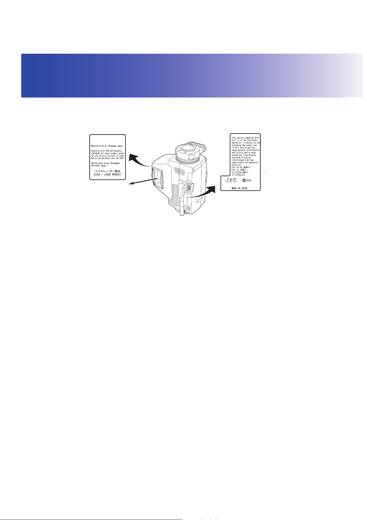
3. LASER SAFETY INFORMATION
RC controller is classified as a class 1 Laser Product and Class 1 LED Product according to IEC
Standard Publication 60825-1 Amd. 2: 2001 and United States Government Code of Federal
Regulation FDA CDRH 21CFR Part1040.10 and 1040.11 (Complies with FDA performance standards
for laser products except for deviations pursuant to Laser Notice No.50, dated July 26, 2001.)
RC-PR3
SOKKIA CO., LTD.
Laser beam is emitted
from here
SOKKIA CO., LTD.
CWarning
• Use of controls or adjustments or performance of procedures other than those specified herein may
result in hazardous radiation exposure.
• Never point the laser beam at another person. If the laser beam strikes skin or an eye, it could cause
serious injury.
• If an eye injury is caused by exposure to the laser beam, seek immediate medical attention from a
licensed ophthalmologist.
CCaution
• Perform checks at start of work and periodic checks and adjustments with the laser beam emitted
under normal conditions.
• When the instrument is not being used, turn OFF the power.
• When disposing of the instrument, destroy the battery connector so that the laser beam cannot be
emitted.
• Operate the instrument with due caution to avoid injuries that may be caused by the laser beam
unintentionally striking a person in the eye. Avoid setting the instrument at heights at which the path
of the laser beam may strike pedestrians or drivers at head height.
• Never point the laser beam at mirrors, windows or surfaces that are highly reflective. The reflected
laser beam could cause serious injury.
6
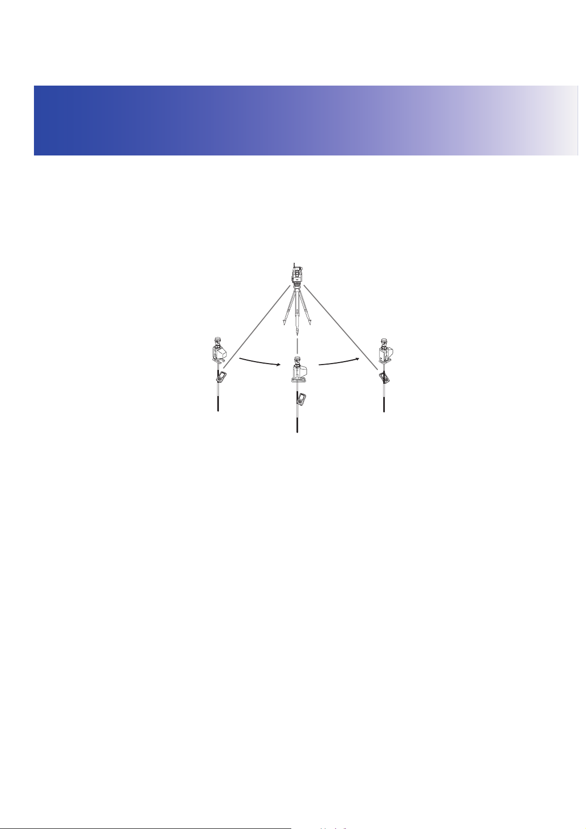
4. ON-DEMAND REMOTE CONTROL FUNCTIONS
The On-demand Remote Control System works as follows. A laser is emitted from the laser projection
port on the RC controller. The total station rotates until its beam detector receives this beam. In this
way the total station is able to detect the position of the RC controller. This operation is called
"Turning".
With the On-demand Remote Control System it is possible for a single operator to perform
measurements, unaided, at multiple measurement points.
The RC controller incorporates a Bluetooth unit which allows simultaneous communication with both
the total station and a data collector.
&Electronic compass
The RC controller is equipped with an electronic compass. Using the Earth’s magnetism, this
compass can detect the RC controller’s horizontal angle from magnetic north.
The current angle is compared with that for the previous measurement to estimate the direction
in which the RC controller moved following the previous measurement. By then taking into
account the aspect of the telescope the RC controller can instruct the total station regarding the
quickest rotation direction to the prism.
The onboard electronic compass was calibrated before being shipped from the factory. A
function within the compass will automatically perform any necessary calibration in response to
changes in the magnetic field.
&Auto Pointing and Auto Tracking
When Auto Pointing is performed, the total station analyses the image of the prism in the field of
view and moves the telescope to sight the center of this prism. When used in conjunction with
the Auto Tracking function, the SRX/NET will then "track" the prism as it is moved to the next
measurement point. When the prism has been "lost" due to an obstacle in the line-of-sight or
operation has been interrupted, the On-demand Remote Control System allows you to quickly
resume operation where you left off.
7
4. ON-DEMAND REMOTE CONTROL FUNCTIONS
G
• Series SRX (Auto Pointing model) and Series 230RM do not support Auto Tracking. Auto Pointing
will be performed instead.
• Series 230RM does not support Auto Pointing with a 360° Prism (ATP1).
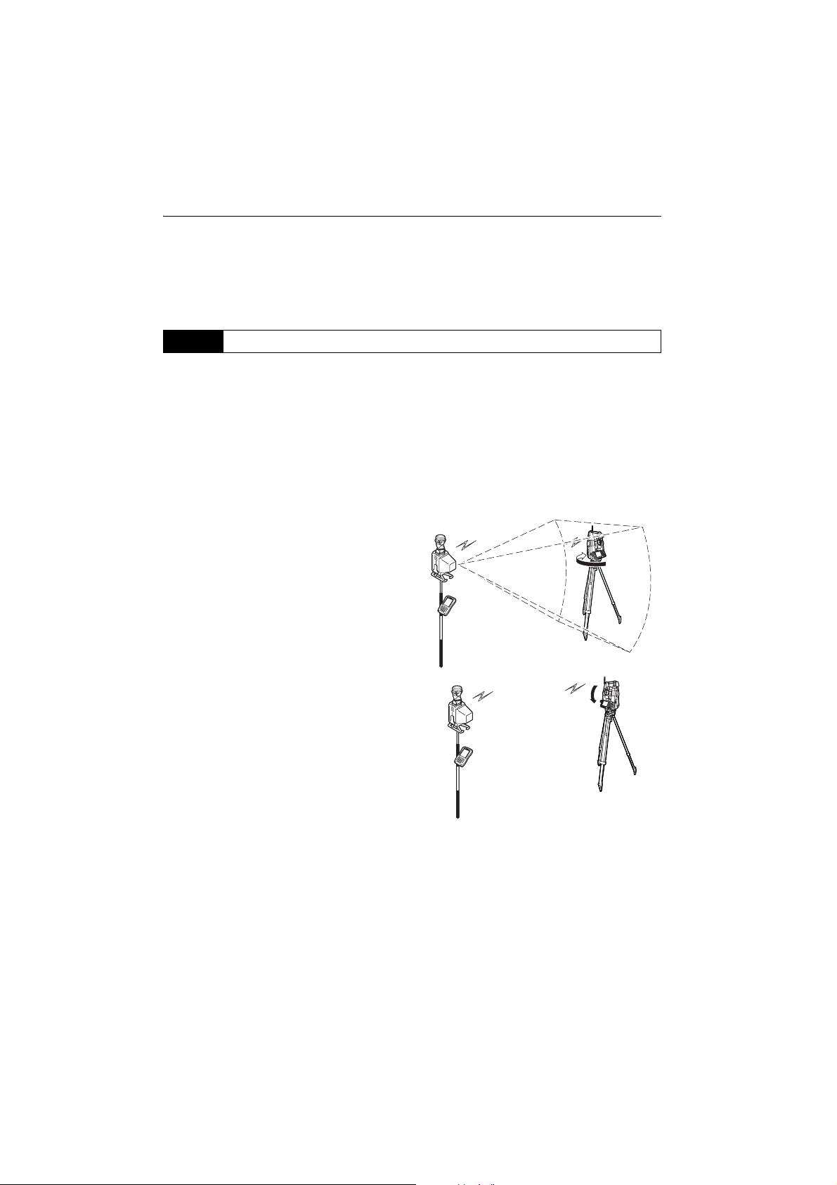
4.1 Turning Operation Flow
To perform Turning, follow the procedure below.
CFor measurement procedure, see "8. BASIC OPERATION"
1. Point the RC controller laser projection port
and prism in the direction of the total station
and instruct the instrument to start Turning. A
laser beam is emitted from the projection port.
At the same time, the Bluetooth unit (COM 1)
relays the instruction to begin Turning.
2. The total station begins to rotate horizontally,
searching for the emitted laser beam. If it is
not detected by the end of the second rotation,
an error occurs.
3. Once the position of the horizontal direction
has been determined, the total station
telescope then begins to rotate along the
vertical axis searching for the position of the
prism.
8

4. ON-DEMAND REMOTE CONTROL FUNCTIONS
4. Once the position of the vertical direction has
been determined an audio sounds and the
total station automatically sights the prism in
the field of view.
5. The SRX/NET tracks a sighted prism as it is
moved to the next measurement point when
Auto Tracking is set.
G
• The time limit for Turning is 60 seconds from the start of Turning operation. If the operation exceeds
this time limit, an error occurs.
$
• When Auto Tracking has been selected, the SRX/NET will start tracking a moving prism once
Turning to that prism has been completed.
9
4. ON-DEMAND REMOTE CONTROL FUNCTIONS
4.2 Measurement Flow
This section explains the measurement procedure for a single operator working from the RC
controller. An operator working alone will need a data collector (available as an optional accessory).
G
• When reflected laser signal is strong (object with high reflection factor):
If there is an object with a high reflection factor, such as a window or standing water, in the vicinity
of the total station/prism, the laser beam may be reflected and Turning operation performed pointing
at the object instead of the RC controller. In this case the accuracy of measurement results may be
adversely affected.
• Fix the pole vertically over the measurement point.
$
• For communication settings for data collectors etc., see the operator’s manual for your respective
device.
XPROCEDURE
1. Connect the instruments.
C "5. SYSTEM CONFIGURATION"
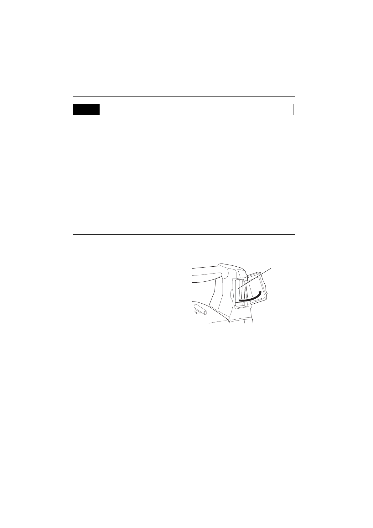
2. Switch ON the power to the total station. Open
the beam detector cover.
3. Set measurement settings for the total station
and select prism type.
C"6.2 Settings for Auto Pointing and Auto
Tracking", "7.4 Setup for Search Before
Distance Measurement"
Prism selection: Operator's Manual
(Series SRX/NET05/NET1) "21.3 EDM
Settings", Series 230RM Operator’s
Manual "23. CHANGING THE
SETTINGS -CONFIGURATION-"
10
Beam
detector

4. Check that SRX/NET Bluetooth settings are
made and the instrument is ready for
communcation.
C"6.1 Settings for Bluetooth
Communication"
After completing the total station preparations
above, the next step is to prepare the RC
controller.
5. When connecting a wireless modem, etc. to
the total station using the relevant cable, set
the communcation settings as shown in
"9.2 Setting Communication Mode".
6. Press the POWER button to switch ON
the RC controller. ● POWER is Lit.
7. Fix the pole vertically over the measurement
point and point the laser projection port of the
RC controller roughly in the direction of the
total station.
If the distance between the total station and the
RC controller is over 100m (normal
atmospheric conditions)/150m (good
atmospheric conditions), set to Far Mode by
pressing the FAR button
( ● FAR is Lit).
CFor atmospheric conditions, see
"8.2.2 Setting Distance Mode"
4. ON-DEMAND REMOTE CONTROL FUNCTIONS
8. When the total station is instructed (using a
data collector) to perform distance
measurement, Turning operation is carried
out. Measurement starts when this Turning
operation is complete.
$
• When returned laser signal is weak (object with low reflection factor):
Even if the laser beam received by the total station has been reflected off an unrelated object, or
sunlight has entered the beam detector, the total station still attempts to complete the stages of
Turning operation as far as Auto Pointing. When the total station judges that the laser beam has not
travelled directly from the RC controller to the beam detector, this position reading taken in error is
nullified and the total station automatically continues Turning operation at the next position.
However, the time limit for Turning is 60 seconds from the start of Turning operation and if the
operation exceeds this time limit, an error occurs.
• Using the SRX/Series230RM guide light when performing Turning operation allows the operator to
confirm whether or not the SRX/Series230RM has correctly located the RC controller laser beam.
When a work site contains highly reflective surfaces it is recommended that measurement is
performed using the guidelight. If the SRX/Series230RM has completed Turning operation pointing
11

4. ON-DEMAND REMOTE CONTROL FUNCTIONS
at the RC controller, both the red and green guide lights are visible from the position of the RC
controller.
C For the total station guide light, see the Series SRX Operator’s Manual/Series 230RM
Operator’s Manual
• With data collectors it is possible to specify the rotation direction for Turning operation before
performing distance measurement.
C For operation procedure, see the operator's manual for your data collector.
& Height difference and slope distance
The maximum measuring range depends on the height difference between the total station and
the RC controller.
The shaded area in the graph below represents the measurement range when set to Far Mode.
Height difference
40m
20m
Measurement
range
12
180m 250m 300m
Slope distance
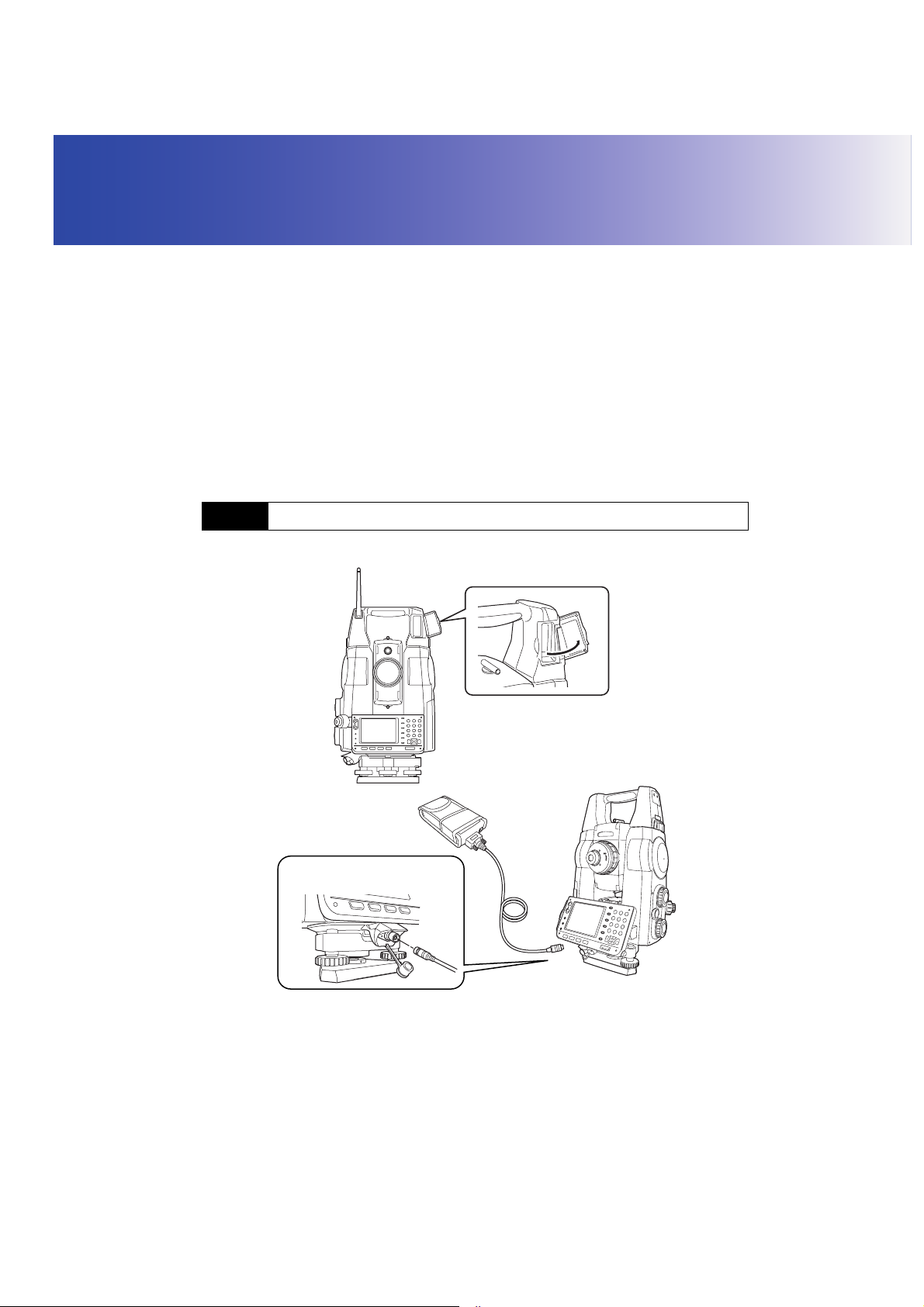
5. SYSTEM CONFIGURATION
The following chapter explains the configuration of total stations and prisms.
Always open the beam detector cover when using the On-demand Remote Control System.
G
• The beam detector cover can be damaged if forced open beyond a certain angle. Always close the
beam detector cover before moving the instrument.
& Using a wireless modem
Serial communication settings must be configured on the RC controller when using a wireless
modem.
Controller"
Make sure the power of all instruments is off before connecting. If the total station and RC
controller are not connected correctly, normal operation cannot be carried out.
Handle cables with care. Grip the connected end of the cable when disconnecting. Do not pull
the cable out with undue force.
5.1 System Configuration of the SRX/NET
●
SRX/NET instrument compatible with On-demand Remote Control System
Handle: RC-TS3
C"9.2 Setting Communication Mode", "9.3 Communication Setup for the RC
Handle: RC-TS3A
Communications and power supply
connector
Series SRX
Wireless modem
13

5. SYSTEM CONFIGURATION
G
• Only instruments incorporating a handle equipped with a beam detector (RC-TS3 or RC-TS3A) can
be used with the On-demand Remote Control System.
• For details regarding wireless modems compatible with an SRX/NET instrument with the RC-TS3A
handle, contact your Sokkia agent.
5.2 System Configuration of the Series 230RM
●
Series 230RM instrument compatible with On-demand Remote Control System
Wireless modem
Series 230RM
G
• For details regarding data collectors and wireless modems compatible with the On-demand Remote
Control System, contact your Sokkia agent.
• Make sure the power of the date collector is off before connecting to the serial cable.
• Series 230RM does not support Auto Pointing with a 360° Prism (ATP1).
14

5. SYSTEM CONFIGURATION
5.3 System Configuration of the RC Controller
For use with other prism types, contact your Sokkia agent.
Grip type
●
Trigger grip for RC-PR3
RC-PRH3
RC
Controller
RC-PR3
One-touch
attachment
SB182A
&
360° Prism
ATP 1
Adapter
SB184
Stainless-steel
prism foot
AP66
Adapter
SB183
Pin-pole
360° Prism
ATP 1
Adapter
SB184
Pin-pole
Adapter
SB183
Pin-pole
Pin-pole
Prism
OR1PA
Adapter
SB184
Pin-pole
15
 Loading...