

Sokkia RADIAN IS Operation Manual

GPS Receiver System
RADIAN
Operations Manual
™
IS
Part Number 750-1-0069 Rev 1

Copyright Notice
© 2000 POINT, Inc. All rights re ser ved .
No part of this publication or the equipment described in it may be reproduced,
translated, stored in a retrieval system, or transmitted in any form or by any
means, elect ro n i c , m e chanical photocopying, recording, or othe rwise, without
prior written permission of Point, Inc. Your rights with regard to this publication
and the equipment are subject to the restrictions and limitations imposed by the
copyright laws of the United States of America (“U.S.A.”) and/or the jurisdiction
in which you are locate d .
Trademark Notice
Sokkia is a trademark of Sokkia Co. Ltd. Spectrum, SDR and Electronic Field
Book are registered trademarks of POINT, Inc. Radian is a trademark of POINT,
Inc. All other product and brand names are trademarks or registered trademarks
of their respective holders.
FCC Notice
The equipment described in this manual has been tested pursuant to Part 15 of
the FCC Rules and found to comply with the limits for a Class A digital device for
use in commercial business, and industrial environments. Operation is subject to
the following two conditions: (1) this device may not cause harmful interference,
and (2) this device must accept any interference received, including interference
that may cause undesired operation. These limits are designed to provide reasonable protection against harmful interference when the equipment is operated in a
commercial environment. The equipment generates, uses, and can radiate radio
frequency energy and, if not in stalled a nd used in accor dance wit h the i nstruc tion
manual, may cause harmful interference to radio and television reception. Operation of this equipment in a residential area is likely to cause harmful interference
in which case the user will be required to correct the interference at his own
expense.
If this equipment does cause interference to radio or television reception, which
can be determined by turning the equipment off and on, you can try to correct the
interference by one or more of the following measures:
• Reorient the receiving antenna.
• Relocate the receiver relative to the equipment which it interferes.
• Power the equipment from a different AC receptacle so that this equipment
and the interfered equipment are on different branch circuits. If necessary,
contact our customer service department or an authorized representative for
additional advice.
CE Notice
Warning: This is a Class A product. In domestic environm ents this product may
cause radio interference in which case the user may be required to take adequate
measures.
Printed on recycled paper.
Part# 750-1-006 9 R ev 1
00-00015-12

Contents
Chapter 1 Introduction 1
1.1 What is the Radian™ IS?....................................................... 1
1.2 Ports and Icons....................................................................... 2
1.3 Features .................................................................................. 3
1.4 Where to Find Information..................................................... 6
1.5 Obtaining Technical Assistance............................................. 6
1.6 Notes, Cautions, and Warnings.............................................. 8
1.7 Radian IS Usage Cautions...................................................... 9
Chapter 2 Setting-Up The Radian IS 10
2.1 Getting Started...................................................................... 10
2.1.1 Setting Up at the Office............................................ 10
2.1.2 Setting Up in the Field.............................................. 11
Chapter 3 Radian IS Components 15
3.1 Enclosure Feature Overview................................................ 15
3.2 Access Door .........................................................................17
3.2.1 Opening and Closing the Access Door..................... 18
3.2.2 Data Card.................................................................. 18
3.2.3 Battery....................................................................... 20
3.3 Ports...................................................................................... 22
3.3.1 Power Port and Power Input..................................... 24
3.3.2 Communications Ports and Power Output................ 24
3.4 Wireless Communications.................................................... 25
3.5 GPS antenna.........................................................................25
3.6 Display panel........................................................................ 26
RADIAN™IS i

Contents
Chapter 4 Using the Radian IS 28
4.1 Power Supply and Control.................................... ...... ..........28
4.1.1 Turn system on..........................................................28
4.1.2 System inactivity.......................................................28
4.1.3 Scheduled session .....................................................29
4.1.4 Data logging interruption..........................................29
4.1.5 Power source.............................................................29
4.1.6 Power consumption......................................... ..........30
4.1.7 Insufficient power.....................................................31
4.2 Display Panel Operations .....................................................31
4.2.1 Power button........... .................................. ...... ..... .....31
4.2.2 Audible annunciator..................................................33
4.2.3 Gauges.......................................................................34
4.3 Internal status indicators .......................................................38
4.3.1 Data card indicator....................................................39
4.3.2 Battery indicator........................................................39
4.4 General Operations...............................................................39
4.5 Data Collection Fundamentals..............................................42
4.5.1 Collecting Data .........................................................42
4.5.2 Defining Data to be Collected...................................45
4.5.3 Data File Naming......................................................48
4.5.4 Data Storage Requirements.......................................50
4.5.5 Resetting the Receiver...............................................50
Appendix A Radian IS Specifications 51
Glossary 55
Index 63
ii RADIAN™IS

Figures
1 Illustration of typical static setup ......................................... 11
2 Illustration of typical base setup .......................................... 12
3 Illustration of vehicle setup .................................................. 13
4 Illustration of typical RTK rover setup ............................... 14
5 Ports and single access door ................................................. 15
6 Mounting socket ..................................................................... 16
7 Display panel and antenna ................................................... 16
8 Access door open .................................................................... 17
9 Access door closed and open ................................................ 18
10 Ports .......................................................................................... 23
11 Antenna ................................................................................... 26
12 Panel display .................................... ...... ..... ............................ 27
13 Data card indicator .................................................................39
14 Battery indicator ..................................................................... 39
15 Radian IS general operations ................................................41
RADIAN™IS iii


Chapter 1 Introduction
1.1 What is the Radian™ IS?
W elcome to the Radian IS Operations Manual. This manual will
provide you with complete information about your Radian IS
(integrated system) and its function.
The Sokkia Radian IS is a state-of-the-art, real-time kinematic,
post-processing, dual-frequency, survey-grade GPS solution.
The Radian IS is the next generation of Radian receiver!
One exciting characteristic of the new Radian IS is that it
features a more powerful GPS engine, yet it uses very little
power. As well, the new Radian IS integrates the receiver,
antenna, data memory and batteries into one lightweight and
rugged component. Integrating the components of the system
means you will have fewer cables to connect.
Wireless data transmission is another exciting feature offered
with the Radian IS. Transferring your data from the receiver to
the data collector through a wireless communications port is a
unique characteristic that eliminates troublesome cables found
in conventional GPS surveying systems.
Surveyors can use the Radian IS for topographic stake-out and
control surveys. As well, the innovative design of the Ra dian IS
receiver will help reduce the man-power necessary because it
eliminates the limitations of traditional survey methods such as
requiring line of sight between points.
The Radian IS is used for RTK or post processing applications,
and it uses proven PAC™ (Pulse Aperture Correlator)
technology, combined with a powerful 32-bit microprocessor.
RADIAN™IS 1
Chapter 1 Introduction
Excellent acquisition and re-acquisition times means this
receiver will operate in environments where signal obstructions
are present and frequent interruption of signals can be
expected.
The Radian IS features a rugged, reliable design for use in
adverse environments, and it will provide years of reliable
operation.
®
Use the Radian IS handheld component (SDR
Radian IS desktop software (Spectrum
®
Survey Suite) with the
Level 5) and the
Radian IS receiver. When used tog ether, you will have a
complete solution that provides powerful state-of-the-art
technology, and an intuitive, easy-to-use GPS system.
1.2 Ports and Icons
This icon is the symbol for communications and identifies
the handheld communications port on the side of the
Radian IS receiver. T he com munications port is also
referred to in this document as COM1.
This icon is the symbol for radio transmission and
identifies the radio communications port on the side of
the Radian IS receiver. The radio communications port is
also referred to in this document as COM2.
This icon is a symbol for supplied-power and identifies
the power port on the side of the Radian IS receiver. The
radio communications port is also referred to in this
document as PWR.
This icon is the symbol for the power button and
identifies the location of the power button on the display
panel of the Radian IS receiver.
2RADIAN™IS

Introduction Chapte r 1
This icon is a symbol for battery and identifies the gauge
that displays the battery life as well as the battery status
indicator. This icon is located on the front display panel of
the Radian IS receiver and inside your Radian IS access
door.
This icon is a symbol for satellite and identifies the gauge
that displays if you have achieved satellite lock. This icon
is located on the front display panel of the Radian IS
receiver.
This icon is a symbol for data card and identifies the
gauge that displays the amount of free space remaining
on your data card as well as the data card status indicator.
This icon is located on the front display panel of the
Radian IS receiver and inside your Radian IS access door.
This icon is a symbol for occupation time and identifies
the period of continuous data of sufficient quality for
post-processing. This icon is located on the front display
panel of the Radian IS receiver.
1.3 Features
The Radian IS is capable of the following positioning modes of
operation:
• Position and observation informat ion
• Navigation information
• Transmit RTK data
• Receive RTK data (2 cm (0.8 in) positioning)
• DGPS (< 1m (< 3.28 ft)) transmit and receive
The Radian IS features are summarized in Table 1. For detailed
information, see Appendix A, Radian IS Specifications.
RADIAN™IS 3

Chapter 1 Introduction
Table 1: Feature Summary
Radian IS Features
General
Rugged shock resistant, water proof (when access door is closed securely), buoyant
enclosure
Wireless controller interface
L1/L2 GPS technology (L1 Channels (C/A code) & L2 Channels (P code))
Capability to log data to a removable data card (CompactFlash card)
Low power consumption (4 W typical)
Scheduled data collection for when user interaction is not required (low power “off” mode
between scheduled data collection sessions)
Patented PAC™ (Pulse Aperture Correlator) technology
Two bi-directional serial ports that have power/data support and can transfer data at rates
up to 115200 bps (bits per second)
Pseudorange measurements
Full-wavelength L1 and L2 carrier measurements
Ionospheric corrections in position calculations
2.5-bit sampling
5 Input / Output strobe signals: mark input (position & time), 1PPS timing output, measure
output, programmable variable-frequency output, solution status output
Fast re-acquisition
Peripheral power supply output COM1 and COM2
Output Data Log Formats
Proprietary ASCII and binary
CMR Standard
NMEA Standard
RINEX Standard
RTCM Standard: Types 1,2,3,9,16,18/19,59N
RTCA Standard: Types 1,7
Data Logging Rates (per second)
Computed Data: Position, speed, direction, & clock offset = 10
Measured Data (Observations): Pseudorange & carrier phase = 10
4RADIAN™IS

Introduction Chapte r 1
Radian IS Features
Receiver Control
Clock drift correction
Ability to save receiver configuration settings, & almanac
Reset (hardware or software activated)
Serial port control
Datum (table or user-definable)
Magnetic variation correction
Undulation (table or user-definable)
Position, height & velocity constraints
Satellite lockout, elevation cut-off and health control
* Note: Specifications are subject to change without notice.
RADIAN™IS 5

Chapter 1 Introduction
1.4 Where to Find Information
This manual provides sufficient information to allow you to
effectively use the Radian IS. In addition to this manual, several
other forms of documentation serve as supporting documents.
• Radian™ IS Jump Start. This document provides general
Radian IS setup procedures. Using this document, you
should be able to correctly and quickly setup your Radian
IS.
• Radian™ IS Quic k Reference Card. This card is a guide
providing “quick” information on running the equipment
in the field.
• Radian™ IS Ad vanced Reference Materials. Located as
http:\\www.sokkia.com\support. This document,
available in electronic copy over the Internet, lists the
Radian IS cable and pinout specifications. As well, this
document contains an advanced glossar y of definitions.
• Planning Reference Manual. This document shows how to
use Planning software to help determine satellite
availability as well as informa tion for understanding and
setting schedules and configura tions for Radian IS.
®
• Spectrum
document provides information for processing and
adjusting your collected data.
• SDR
provide information for using the SDR Level 5 softw are.
Survey Suite Reference Manual.This
®
Level 5 User/Reference Manuals. These documents
1.5 Obtaining Technical Assistance
When contacting customer support, have available:
• the firmware version number
• a concise des c ription of the problem
6RADIAN™IS

Introduction Chapte r 1
Technical support for this product is available from the
distributor where you purchased it. Y ou also may contact one of
the Sokkia subsidiaries listed below.
Europe
Sokkia B.V.
Businesspark De Vaart
Damsluisweg 1, 1332 EA Almere
P.O. Box 1292, 1300 BG Almere
The Netherlands
Phone 036-53- 2 2-880
Fax 036-53-26-241
New Zealand
Sokkia New Zealand
20 Constellation Drive
Mairangi Bay, Auckland 10
C.P.O. Box 4464
Auckland, New Zealand
Phone 64-9-479-3064
Fax 64-9-79-3066
Central & South America
Sokkia Central & South America
1200 NW 78 Avenue, Suite 109
Miami, FL, USA 33126
Phone 1-305-599-4701
Fax 1-305-599-4703
USA
Sokkia Corporation
16900 W 118th Te rr
Olathe, KS, USA 66061
Phone 1-800-257-2552
Fax 1-913-492-0188
Canada
1050 Stacey Court
Mississauga, Ontario
L4W 2X8 Canada
Phone 1-905-238-5810
Fax 1-905-238-9383
Australia
Sokkia Pty. Ltd.
Rydalmer e Metr o Cent r e
Unit 29,38-46 Sou t h St reet
Rydal mere NSW 2116
Australia
Phone 61-2-9 63 8-0055
Fax 61-2-9638-3933
U.K.
Sokkia Ltd
Electra Way
Crewe Business Park
Crewe, Cheshire, CW1 1ZT
United Kingdom
Phone 01270-250525
Fax 01270-250533
Africa
265 Von Willich Ave.
Centurion, 0157
Republic of South Africa
Phone 27 12 6637999
Fax 27 12 663799 8
Asia
Sokkia Singapore Pte. Ltd.
401 Commonwealth Drive
#06-01 Haw Pa r Technocentre
Singapore 149598
Phone 65-479-3966
Fax 65-479-4 966
RADIAN™IS 7

Chapter 1 Introduction
1.6 Notes, Cautions, and Warnings
Notes, Cautions, and Warnings stress important information
regarding the installation, configuration, and operation of the
Radian IS receiver.
* Note: Notes outline important information of a general
nature.
CAUTION
Cautions inf o r m of po s s ib l e so u rces of difficulty or si t u ations
that may cause damage to the product.
WARNING
Warnings inform of situations that ma y cause you harm.
8RADIAN™IS

Introduction Chapte r 1
1.7 Radian IS Usage Cautions
CAUTION
• This device incorporates circuitry to absorb most static
discharges. However, severe static shock may cause inaccurate
operation of the unit. Use anti-stat ic precautions where possible.
• This device is a precision instrument. Although it is designed
for rugged operating con dition s, it perf orms best when h andled
with care.
• When the access cover for Radian IS is closed and latched, and
the port covers are closed, the enclosure is sealed to provide
protection against adverse environmental conditions. To
minimize the possibility of damage, always keep the access
door closed and latched except wh en exchanging data cards or
batteries and keep the ports covered except when in use.
• Do not eject the da ta car d w hile the Radi an IS is logg ing data , or
you may lose part of, or your entire, data file.
• The Radian IS can accept an input supply voltage in the range
+9 to +18 V DC. This may not be the same range as other Sokkia
products with which you are familiar. Do not operate the
Radian IS outside the specified voltage range.
• Drawing more than the specified maximum current (1 amp
combined total) from the two COM ports will cause an internal
fuse to interrupt the cu rrent. If this happens, immediately
reduce the load and allow the unit to automatically reset its
protection circuitry.
• We recommend that you do not use the Radian IS on a moving
vehicle.
RADIAN™IS 9

Chapter 2 Setting-Up The Radian IS
2.1 Getting Started
Setting up the Radian IS is a straightforward process, whether
you are in the field (collecting data) or back at the office
(configuring the Radian IS, or transferring collected data to
your PC for post-processing).
CAUTION
See Section 1.7, Radian IS Usage Cautions, on Page 9 for a list
of items you should be aware of as you set up and use the
Radian IS.
2.1.1 Setting Up at the Office
For information on setting up your rover or base Radian IS,
refer to the setup steps in your Radian IS Jump Start.
A typical Radian IS setup at the office may be when the PC is
connected to the Radian IS COM1 port and internal batteries are
powering the Radian IS. An office setup can be used to load a
schedule on the Radian IS using Planning software, or to
transfer collected data from the Radian IS to a PC.
Perform the following steps to setup Radian IS in the office:
1. Place the Radian IS on a desk or other suitable work
surface.
2. Using the PC Data cable, connect the PC to COM1 on the
Radian IS.
3. If not already installed, connect the Radian IS internal
batteries to the internal battery connectors.
RADIAN™IS 10

Setting-Up The Radian IS Chapter 2
4. Turn on the Radian IS.
5. Communicate with the Radian IS, using the Planning
software (Refer to your Planning Reference Manual), to setup
configurations or setup a data-collection sched ule. Use any
Sokkia software to transfer data to the PC (For example,
Spectrum Survey).
The sections of Chapter 3, Radian IS Components, give further
details on Steps two and three, while Chapter 4, Using the
Radian IS, will discuss Step four.
2.1.2 Setting Up in the Field
The Radian IS can be used for static or kinematic survey, as a
base or rover. This section will give an overview of the
equipment and setup for typical uses of the system, but for
information on setting up your Radian IS for field operations,
refer to the setup steps in your Radian IS Jump Start.
2.1.2.1 Typical static setup
For static survey , the Radian IS is put on a fixed height tripod or
on a traditional tripod with a tribrach a nd adapter. The system
is operated using the power switch or using a handheld
through a wireless or cable connection. The system is powered
using internal batteries or optionally a larger external battery.
Figure 1: Illustration of typical static setup
RADIAN™IS 11

Chapter 2 Setting-Up The Radian IS
2.1.2.2 Typical base setup
An RTK base station setup will typically consist of a standard
wood tripod or fixed height alumin um GPS tripod, Radian IS
receiver, PDL radio/modem, radio antenna mount/cable, and
antenna and radio antenna mounting bracket. The base system
is typically powered by a large external battery (SLA battery)
that powers both the radio and the Radian IS. Typically the base
radio will hook onto the tripod and the base battery will sit on
the ground.
+
-
Figure 2: Illustration of typical base setup
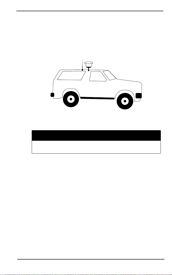
2.1.2.3 Vehicle base setup
Radian IS may be mounted on a vehicle and used as a base.
Typically the Radian IS and the radio antenna m ay be screwed
onto magnetic mounts attached to the roof of a vehicle. The
Radian IS may be powered through the cigarette lighter in the
vehicle.
While it is convenient to use your Radian IS mo unted to a
vehicle for t he ba se stat io n, s mal l mo veme nt s c aused b y get ti ng
into and out of the vehicle, as well as wind and terrain
conditions can cause small or very slow movements to occur,
which will translate to an error of equal proportion at the
rover’s location. Only mount your Radian IS on your vehicle if
12 RADIAN™IS
Setting-Up The Radian IS Chapter 2
you know that you will not be getting in and out of your
vehicle, or if the small amount of error caused is acceptable for
your purposes.
For a base configuration, you must not move the vehicle during
operations.
Figure 3: Illustration of vehicle setup
CAUTION
We recommend that you do not use the Radian IS on a
moving vehicle.
2.1.2.4 Typical rover setup
A typical rover RTK setup consists of an adjustable pole, a PDL
radio/modem, whip antenna, Radian IS receiver, controller
bracket and controller.Typically the PDL and Radian IS mount
on the top of the pole and the handheld bracket will attach near
the mid-section of the pole with the handheld controller
RADIAN™IS 13

Chapter 2 Setting-Up The Radian IS
attached. If the system is to remain standing, a bipod can be
attached to the pole. The typical rover setup would not require
the use of a backpack.
Figure 4: Illustration of typical RTK rover setup
14 RADIAN™IS

Chapter 3 Radian IS Components
The Radian IS enclosure houses your system’s antenna, power
supply, memory and GPS card. By incorporating these
components into a single unit, a backpack is no longer needed
when using the system.
3.1 Enclosure Feature Overview
The Radian IS enclosure has a single access door, providing
easy access to the batteries and data card. For more information
on the access door, see Section 3.2, Access Door, on Page 17.
As well, three ports, featuring easy-to-open, permanently
attached covers, are accessible from the side of the unit. For
more information on the ports, see Section 3.3, Ports, on Page
22.
Refer to Figure 5 for a view of the access door and the ports
with covers attached.
Figure 5: Ports and single access door
RADIAN™IS 15
Chapter 3 Radian IS Components
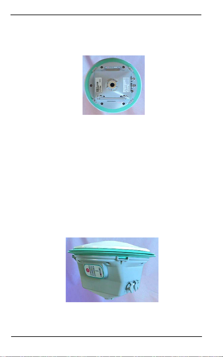
The underside of the Radian IS enclosure has a standard 5/8”
mounting socket for mounting the Radian IS on a tripod or
survey pole. Refer to Figure 6 for a view of the mounting socket.
Figure 6: Mounting socket
The top of the Radian IS is the antenna, and it is surrounded by
a brightly colored rubber bumper. For more information on the
antenna, see Section 3.5, GPS antenna, on Page 25.
The side of the Radian IS has a display panel that enables you to
turn on and monitor the system. Brightly colored LEDs display
the status of your system and alert you to errors when possible.
For more information on the display panel, s ee Section 3.6,
Display panel, on Page 26.
Refer to Figure 7 for a view of the antenna and display pa nel.
Figure 7: Display panel and antenna
16 RADIAN™IS
Radian IS Components Chapter 3
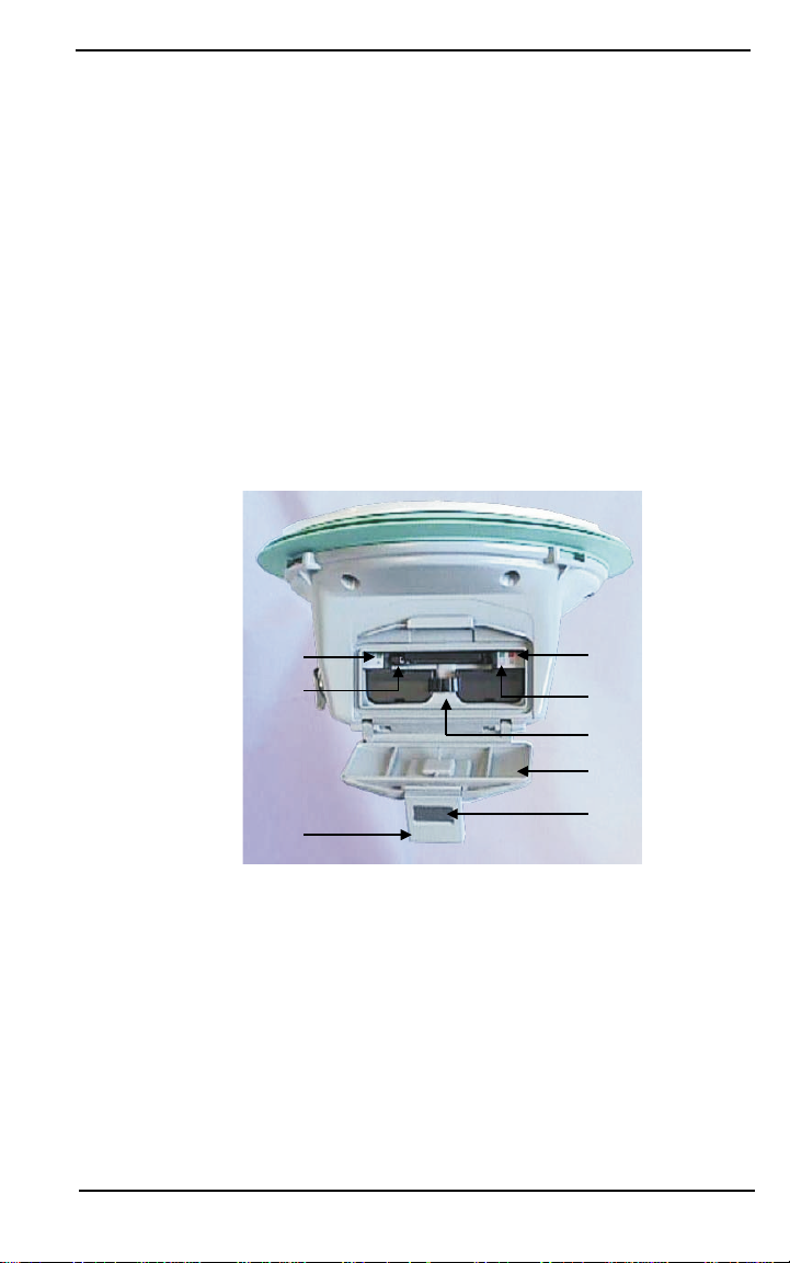
3.2 Access Door
The Radian IS access door provides easy accessibility, without
the use of tools, to the data card and batteries. For information
on inserting and removing the data card and batteries, see
Section 3.2.2.1, Inserting and remo ving the data car d, on Page 19
and Section 3.2.3.1, Inserting and rem oving th e batte ry, Page 21. As
well, three status indicators providing information about the
internal batteries and data card are visible fro m in side this
compartment (See Section 4.3, Internal status indicators, on Page
38). Refer to Figure 8 for a view of the access door and
compartment.
1
3
2
4
5
6
8
Figure 8: Access door open
# Description # Description
1 Battery A status indicator 5 Battery clip and release
2 Battery B status indicator 6 Access door
3 Data card eject 7 Latch release
4 Data card status indicator 8 Access door handle
RADIAN™IS 17
7
 Loading...