

Sokkia X-1000 series, iX-500 series, iX-1001, iX-1005, iX-503 Operator's Manual
...
SURVEYING INSTRUMENTS
iX-1000 series
iX-500 series
intelligence X-ellence Station
Class 3R Laser Product
OPERATOR'S MANUAL
1008477-02-B

HOW TO READ THIS MANUAL
Li-ion
S Li-ion
This is the mark of the Japan Surveying Instruments Manufacturers Association.
Thank you for selecting the iX-1000/500 series.
• Please read this Operator’s manual carefully, before using this product.
• iX has a function to output data to a connected host computer. Command operations from a host computer
can also be performed. For details, refer to "Communication manual" and ask your local dealer.
• The specifications and general appearance of the instrument are subject to change without prior notice and
without obligation by TOPCON CORPORATION and may differ from those appearing in this manual.
• The content of this manual is subject to change without notice.
• Some of the diagrams shown in this manual may be simplified for easier understanding.
• Always keep this manual in a convenient location and read it when necessary.
• This manual is protected by copyright and all rights are reserved by TOPCON CORPORATION.
• Except as permitted by Copyright law, this manual may not be copied, and no part of this manual may be
reproduced in any form or by any means.
• This manual may not be modified, adapted or otherwise used for the production of derivative works.
Symbols
The following conventions are used in this manual.
: Indicates precautions and important items which should be read before operations.
: Indicates the chapter title to refer to for additional information.
: Indicates supplementary explanation.
: Indicates an explanation for a particular term or operation.
[MEAS] etc. : Indicates Operation icons on the display and window dialog buttons.
{ESC} etc. : Indicates keys on the operation panel.
<Screen title> etc.: Indicates screen titles.
Notes regarding manual style
• Except where stated, “iX” means iX-1000/500 series in this manual.
• Model with display on the both sides is available as a factory option depending on the country of purchase.
• Location of Operation icons in screens used in procedures is based on the factory setting. It is possible to
change the allocation of Operation icons.
"19. CHANGING THE SETTINGS"
• Except where stated, instrument with RC Handle is used for illustration.
• Learn basic operations in "4. PRODUCT OUTLINE" and "5. BASIC OPERATION" before you read each
measurement procedure. For selecting options and inputting figures, see "5.1 Basic Key Operation".
• Measurement procedures are based on continuous measurement. Some information about procedures when
other measurement options are selected can be found in “Note” ().
• KODAK is a registered trademark of Eastman Kodak Company.
• Bluetooth
• Windows is registered trademarks of Microsoft Corporation.
• All other company and product names featured in this manual are trademarks or registered trademarks of
each respective organization.
®
is a registered trademark of Bluetooth SIG, Inc.
i

CONTENTS
1. PRECAUTIONS FOR SAFE OPERATION ................................................................... 1
2. PRECAUTIONS .............................................................................................................4
3. LASER SAFETY INFORMATION .................................................................................. 7
4. PRODUCT OUTLINE .................................................................................................... 9
4.1 Parts of the Instrument ......................................................................................... 9
4.2 Mode Structure ................................................................................................... 13
4.3 Bluetooth Wireless Technology/Wireless LAN ................................................... 14
5. BASIC OPERATION ....................................................................................................16
5.1 Basic Key Operation ...........................................................................................16
5.2 Display Functions ............................................................................................... 18
5.3 Inputting Characters using the Input Panel ........................................................ 22
5.4 Starkey Mode ..................................................................................................... 23
6. USING THE BATTERY ............................................................................................... 28
6.1 Battery Charging .................................................................................................28
6.2 Installing/Removing the Battery .......................................................................... 29
7. SETTING UP THE INSTRUMENT .............................................................................. 30
7.1 Centering ............................................................................................................30
7.2 Levelling .............................................................................................................31
8. POWER ON/OFF ........................................................................................................ 33
8.1 Configuring the Touch Panel .............................................................................. 34
8.2 Resolving Software Issues ................................................................................. 34
8.3 Powering ON/OFF from an External Instrument .................................................35
9. CONNECTING TO EXTERNAL DEVICES .................................................................. 36
9.1 Wireless Communication using Bluetooth Technology ......................................36
9.2 Communication between the iX and Companion Device ................................... 39
9.3 Connection via RS232C Cable ........................................................................... 40
9.4 Wireless LAN Settings and Communication ....................................................... 41
9.5 Cellular Settings and Communication ................................................................ 44
9.6 Connecting via USB Cable .................................................................................47
9.7 Inserting USB Flash Drive .................................................................................. 50
10. TARGET SIGHTING AND MEASUREMENT .............................................................. 51
10.1 Auto Pointing and Auto Tracking Settings .......................................................... 53
10.2 Auto Pointing and Auto Tracking Function for Target Sighting/Measurement .... 56
10.3 Manually Sighting the Target .............................................................................. 59
11. ANGLE MEASUREMENT ........................................................................................... 60
11.1 Measuring the Horizontal Angle between Two Points (Horizontal Angle 0°) ...... 60
11.2 Setting the Horizontal Angle to a Required Value (Horizontal Angle Hold) ........ 61
11.3 Turning the Instrument from the Reference Angle to a Specified Angle ............62
11.4 Angle measurement and Outputting the Data .................................................... 63
12. DISTANCE MEASUREMENT ..................................................................................... 64
12.1 Returned Signal Checking ..................................................................................64
12.2 Distance and Angle Measurement ..................................................................... 66
12.3 Using the Guide Light in Distance Measurement ............................................... 66
12.4 Distance Measurement and Outputting the Data ............................................... 68
12.5 REM Measurement .............................................................................................69
13. COORDINATE MEASUREMENT ................................................................................ 71
13.1 Entering Instrument Station Data ....................................................................... 71
13.2 Azimuth Angle Setting ........................................................................................ 72
13.3 3-D Coordinate Measurement ............................................................................ 74
14. RESECTION MEASUREMENT ................................................................................... 76
14.1 Coordinate Resection Measurement .................................................................. 77
ii

14.2 Height Resection Measurement ......................................................................... 81
15. SETTING-OUT MEASUREMENT ...............................................................................85
15.1 Distance Setting-out Measurement .................................................................... 86
15.2 Using the Guide Light in Setting-out Measurement ............................................ 86
15.3 Coordinates Setting-out Measurement ............................................................... 90
15.4 REM Setting-out Measurement .......................................................................... 93
16. OFFSET MEASUREMENT ......................................................................................... 96
16.1 Offset Single-distance Measurement ................................................................. 96
16.2 Offset Angle Measurement ................................................................................. 98
16.3 Offset Two-distance Measurement ..................................................................... 99
17. MISSING LINE MEASUREMENT ............................................................................. 102
17.1 Measuring the Distance between 2 or more Points .......................................... 102
17.2 Changing the Starting Point .............................................................................. 104
18. SURFACE AREA CALCULATION ............................................................................ 105
19. CHANGING THE SETTINGS ....................................................................................108
19.1 Observation Conditions - Angle/Tilt .................................................................. 108
19.2 Observation Conditions - Dist ...........................................................................109
19.3 Observation Conditions - Reflector (Target) ..................................................... 112
19.4 Observation Conditions - Atmosphere .............................................................. 114
19.5 Instrument Conditions - Display ........................................................................116
19.6 Instrument Conditions - Power ......................................................................... 118
19.7 Instrument Conditions - Instrument ..................................................................119
19.8 Instrument Conditions - Unit .............................................................................120
19.9 Instrument Conditions - Password ....................................................................121
19.10Customizing Screen Controls ...........................................................................122
19.11Instrument Conditions - Date and Time ............................................................ 122
19.12Allocating Operating Icons ................................................................................125
19.13Changing Starkey Mode Icons ......................................................................... 128
19.14Restoring Default Settings ................................................................................ 130
20. WARNING AND ERROR MESSAGES ..................................................................... 131
21. CHECKS AND ADJUSTMENTS ............................................................................... 134
21.1 Circular Level ....................................................................................................134
21.2 Tilt Sensor ........................................................................................................ 135
21.3 Reticle ...............................................................................................................136
21.4 Collimation ........................................................................................................138
21.5 Image Sensor Reticle .......................................................................................139
21.6 Optical Plummet ............................................................................................... 142
21.7 Additive Distance Constant ..............................................................................143
21.8 Laser Plummet (Optional Accessory) ...............................................................144
22. CLOUD OAF ..............................................................................................................147
22.1 OAF Online Update ..........................................................................................147
22.2 OAF Offline Update .......................................................................................... 150
23. POWER SUPPLY SYSTEM ......................................................................................152
24. TARGET SYSTEM .................................................................................................... 153
25. ACCESSORIES .........................................................................................................155
26. SPECIFICATIONS ..................................................................................................... 158
27. EXPLANATIONS ...................................................................................................... 165
27.1 High Accuracy with the 360° Prism .................................................................. 165
27.2 Manually Indexing the Vertical Circle by Face 1/2 Measurement ..................... 166
27.3 Correction for Refraction and Earth Curvature ................................................. 167
28. REGULATIONS .........................................................................................................168
29. INDEX ........................................................................................................................171
iii

1. PRECAUTIONS FOR SAFE OPERATION
For the safe use of the product and prevention of injury to operators and other persons as well as prevention
of property damage, items which should be observed are indicated by an exclamation point within a triangle
used with WARNING and CAUTION statements in this operator’s manual.
The definitions of the indications are listed below. Be sure you understand them before reading the manual’s
main text.
Definition of Indication
General
WARNING
CAUTION
This symbol indicates items for which caution (hazard warnings inclusive) is urged. Specific
details are printed in or near the symbol.
This symbol indicates items which are prohibited. Specific details are printed in or near the
symbol.
This symbol indicates items which must always be performed. Specific details are printed in
or near the symbol.
Ignoring this indication and making an operation error could possibly result
in death or serious injury to the operator.
Ignoring this indication and making an operation error could possibly result
in personal injury or property damage.
Warning
Do not use the unit in areas exposed to high amounts of dust or ash, in areas where there is
inadequate ventilation, or near combustible materials. An explosion could occur.
Do not perform disassembly or rebuilding. Fire, electric shock, burns, or hazardous radiation
exposure could result.
Never look at the sun through the telescope. Loss of eyesight could result.
Do not look at reflected sunlight from a prism or other reflecting object through the telescope.
Loss of eyesight could result.
Direct viewing of the sun during sun observation will cause loss of eyesight. Use solar filter
(option) for sun observation.
When securing the instrument in the carrying case make sure to set all the locks. Failure to
do so could result in the instrument falling out while being carried, causing injury.
Caution
Do not use the carrying case as a footstool. The case is slippery and unstable so a person
could slip and fall off it.
Do not place the instrument in a damaged case or in a case with a damaged belt. The case
or instrument could be dropped and cause injury.
Do not touch the instrument or look through the telescope while the motor is in operation.
Injury could result.
Do not wield or throw the plumb bob. A person could be injured if struck.
Secure handle to main unit. Failure to properly secure the handle could result in the unit
falling off while being carried, causing injury.
Tighten the adjustment tribrach clamp securely. Failure to properly secure the clamp could
result in the tribrach falling off while being carried, causing injury.
1

Power Supply
1. PRECAUTIONS FOR SAFE OPERATION
Warning
Do not disassemble or rebuild the battery or the battery charger, nor expose to heavy shocks
or vibration. Sparking, fire, electric shock or burns could result.
Do not short circuit. Heat or ignition could result.
Do not place articles such as clothing on the battery charger while charging batteries. Sparks
could be induced, leading to fire.
Do not use voltage other than the specified power supply voltage. Fire or electrical shock
could result.
Do not use batteries other than those designated. An explosion could occur, or abnormal
heat generated, leading to fire.
Do not use damaged power cords, plugs or loose outlets. Fire or electric shock could result.
Do not use power cords other than those designated. Fire could result.
Use only the specified battery charger to recharge batteries. Other chargers may be of
different voltage rating or polarity, causing sparking which could lead to fire or burns.
Do not use the battery or charger for any other equipment or purpose. Fire or burns caused
by ignition could result.
Do not heat or throw batteries or chargers into fire. An explosion could occur, resulting in
injury.
Tripod
To prevent shorting of the battery in storage, apply insulating tape or equivalent to the
terminals. Otherwise shorting could occur resulting in fire or burns.
Do not use the battery or the battery charger if its terminals are wet. Resultant poor contact
or shorting could lead to fire or burns.
Do not connect or disconnect power supply plugs with wet hands. Electric shock could
result.
Caution
Do not touch liquid leaking from batteries. Harmful chemicals could cause burns or blisters.
Caution
When mounting the instrument to the tripod, tighten the centering screw securely. Failure to
tighten the screw properly could result in the instrument falling off the tripod, causing injury.
Tighten securely the leg fixing screws of the tripod on which the instrument is mounted.
Failure to tighten the screws could result in the tripod collapsing, causing injury.
Do not carry the tripod with the tripod shoes pointed at other persons. A person could be
injured if struck by the tripod shoes.
Keep hands and feet away from the tripod shoes when fixing the tripod in the ground. A hand
or foot stab wound could result.
Tighten the leg fixing screws securely before carrying the tripod. Failure to tighten the
screws could lead to the tripod legs extending, causing injury.
2

Wireless technologies
1. PRECAUTIONS FOR SAFE OPERATION
Warning
Do not use within the vicinity of hospitals. Malfunction of medical equipment could result.
Use the instrument at a distance of at least 22 cm from anyone with a cardiac pacemaker.
Otherwise, the pacemaker may be adversely affected by the electromagnetic waves
produced and cease to operate as normal.
Do not use onboard aircraft. The aircraft instrumentation may malfunction as a result.
Do not use within the vicinity of automatic doors, fire alarms and other devices with
automatic controls as the electromagnetic waves produced may adversely affect operation
resulting in an accident.
3
2. PRECAUTIONS
Charging Battery
• Be sure to charge the battery within the charging temperature range.
Charging temperature range : 0 to 40°C
• Use only the specified battery or the battery charger. Failures caused by using other batteries or battery
chargers are out of warranty including the main unit.
Warranty policy for Battery
• Battery is an expendable item. The decline in retained capacity depending on the repeated charging/
discharging cycle is out of warranty.
Bluetooth Wireless Technology/Wireless LAN
• Bluetooth function may not be built in depending on telecommunications regulations of the country or the area
where the instrument is purchased. Contact your local dealer for the details.
Telescope
• Aiming the telescope at the sun will cause internal damage to the instrument. Use the solar filter when
observing the sun.
"25. ACCESSORIES"
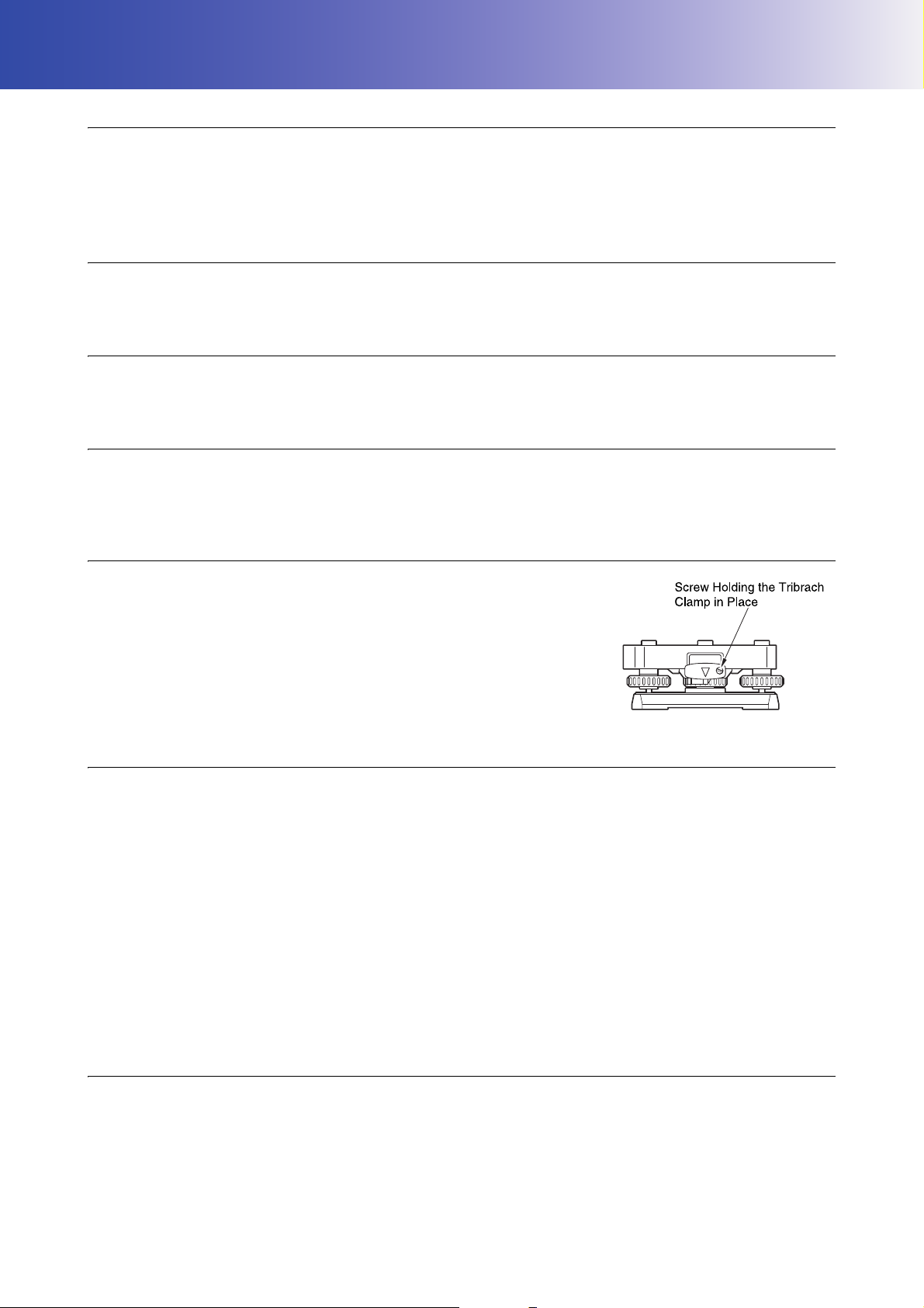
Tribrach Clamp and Handle
• When the instrument is shipped, the tribrach clamp is held firmly in place with
a locking screw to prevent the instrument from shifting on the tribrach. Before
using the instrument the first time, loosen this screw with a screwdriver. And
before transporting it, tighten the locking screw to fasten the tribrach clamp
in place so that it will not shift on the tribrach.
• The handle of the instrument can be removed. When operating the
instrument with the handle attached, always make sure that the handle is
securely fixed to the instrument body with the handle locks.
Precautions concerning water and dust resistance
The instrument conforms to IP65 specifications for waterproofing and dust resistance when battery cover,
connector cap and the external interface hatch are closed.
• Be sure to correctly attach the connector caps to protect the instrument from moisture and dust particles when
the connector is not in use.
• Make sure that moisture or dust particles do not come in contact with the terminal or connectors.
Operating the instrument with moisture or dust on the terminal or connectors may cause damage to the
instrument.
• Make sure that the inside of the carrying case and the instrument are dry before closing the case. If moisture
is trapped inside the case, it may cause the instrument to rust.
• If there is a crack or deformation in the rubber packing for the battery cover or external interface hatch, stop
using and replace the packing.
• To retain the waterproof property, it is recommended that you replace the rubber packing once every two
years. To replace the packing, contact your local dealer.
The Lithium Battery
• The lithium battery is used to maintain the Calendar & Clock function. It can back up data for approximately
5 years of normal use and storage (Temperature = 20°, humidity = about 50%), but its lifetime may be shorter
depending on circumstances.
4

2. PRECAUTIONS
Tribrach
• Always use the tribrach provided. During a traverse observation, it is recommended to use the same type of
tribrach for the target as well for accurate observations.
Backing up data
• Data should be backed up (transferred to an external device etc.) on a regular basis to prevent data loss.
Other precautions
• Never place the instrument directly on the ground. Sand or dust may cause damage to the screw holes or the
centering screw on the base plate.
• Do not perform vertical rotation of the telescope when using the lens hood, diagonal eyepiece, or solar filter.
Such accessories may strike the instrument causing damage.
• Protect the instrument from heavy shocks or vibration.
• Protect the instrument from rain or drizzle with an umbrella or waterproof cover.
• Never carry the instrument on the tripod to another site.
• Turn the power off before removing the battery.
• Remove the battery before placing the instrument in its case.
• Make sure that the instrument and the protective lining of the carrying case are dry before closing the case.
The case is hermetically sealed and if moisture is trapped inside, the instrument could rust.
• Consult your local dealer before using the instrument under special conditions such as long periods of
continuous use or high levels of humidity. In general, special conditions are treated as being outside the scope
of the product warranty.
Maintenance
• Wipe off moisture completely if the instrument gets wet during survey work.
• Always clean the instrument before returning it to the case. The lens requires special care. First, dust it off
with the lens brush to remove tiny particles. Then, after providing a little condensation by breathing on the
lens, wipe it with the silicon cloth.
• If the display is dirty, carefully wipe it with a soft, dry cloth. To clean other parts of the instrument or the carrying
case, lightly moisten a soft cloth in a mild detergent solution. Wring out excess water until the cloth is slightly
damp, then carefully wipe the surface of the unit. Do not use any alkaline cleaning solutions, alcohol, or any
other organic solvents on the instrument or display.
For temporal de-activating the touch panel, see "5.2 Display Functions Temporarily de-activating the
touch panel",
• Store the instrument in a dry room where the temperature remains fairly constant.
• Check the tripod for loose fit and loose screws.
• If any trouble is found on the rotatable portion, screws or optical parts (e.g. lens), contact your local dealer.
• When the instrument is not used for a long time, check it at least once every 3 months.
"21. CHECKS AND ADJUSTMENTS"
• When removing the instrument from the carrying case, never pull it out by force. The empty carrying case
should be closed to protect it from moisture.
• Check the instrument for proper adjustment periodically to maintain the instrument accuracy.
5

2. PRECAUTIONS
Exporting this product (Relating EAR)
• This product is equipped with the parts/units, and contains software/technology, which are subject to the EAR
(Export Administration Regulations). Depending on countries you wish to export or bring the product to, a US
export license may be required. In such a case, it is your responsibility to obtain the license. The countries
requiring the license as of May 2013 are shown below. Please consult the Export Administration Regulations
as they are subject to change.
North Korea
Iran
Syria
Sudan
Cuba
URL for the EAR of the US: http://www.bis.doc.gov/policiesandregulations/ear/index.htm
Exporting this product (Relating telecommunications regulations)
• Wireless communication module is incorporated in the instrument. Use of this technology must be compliant
with telecommunications regulations of the country where the instrument is being used. Even exporting the
wireless communication module may require conformity with the regulations. Contact your local dealer in
advance.
Exceptions from responsibility
• The user of this product is expected to follow all operating instructions and make periodic checks (hardware
only) of the product’s performance.
• The manufacturer, or its representatives, assumes no responsibility for results of faulty or intentional usage
or misuse including any direct, indirect, consequential damage, or loss of profits.
• The manufacturer, or its representatives, assumes no responsibility for consequential damage, or loss of
profits due to any natural disaster, (earthquake, storms, floods etc.), fire, accident, or an act of a third party
and/or usage under unusual conditions.
• The manufacturer, or its representatives, assumes no responsibility for any damage (change of data, loss of
data, loss of profits, an interruption of business etc.) caused by use of the product or an unusable product.
• The manufacturer, or its representatives, assumes no responsibility for any damage, and loss of profits
caused by usage different to that explained in the operator’s manual.
• The manufacturer, or its representatives, assumes no responsibility for damage caused by incorrect
operation, or action resulting from connecting to other products.
6
3. LASER SAFETY INFORMATION
࣮ࣞࢨගࡢฟཱྀ
AVOID EXPOSURE-Laser radiation
is emitted from this aperture.
(On the side of the telescope)
Laser beam
emitted from here
(Laser plummet
mounted model only)
Laser beam emitted from here
(Laser plummet mounted model only)
┠ࡢ┤᥋⿕ࡤࡃࢆ㑊ࡅࡿࡇ
ࢡࣛࢫ5࣮ࣞࢨ〇ရ
-,6&
LASER RADIATION
AVOID DIRECT EYE EXPOSURE
0$;P:/'QP
MAX 5mW LD 625-695nm
CLASS3R LASER PRODUCT
IEC 60825-1 Ed.3.0: 2014
࣮ࣞࢨග
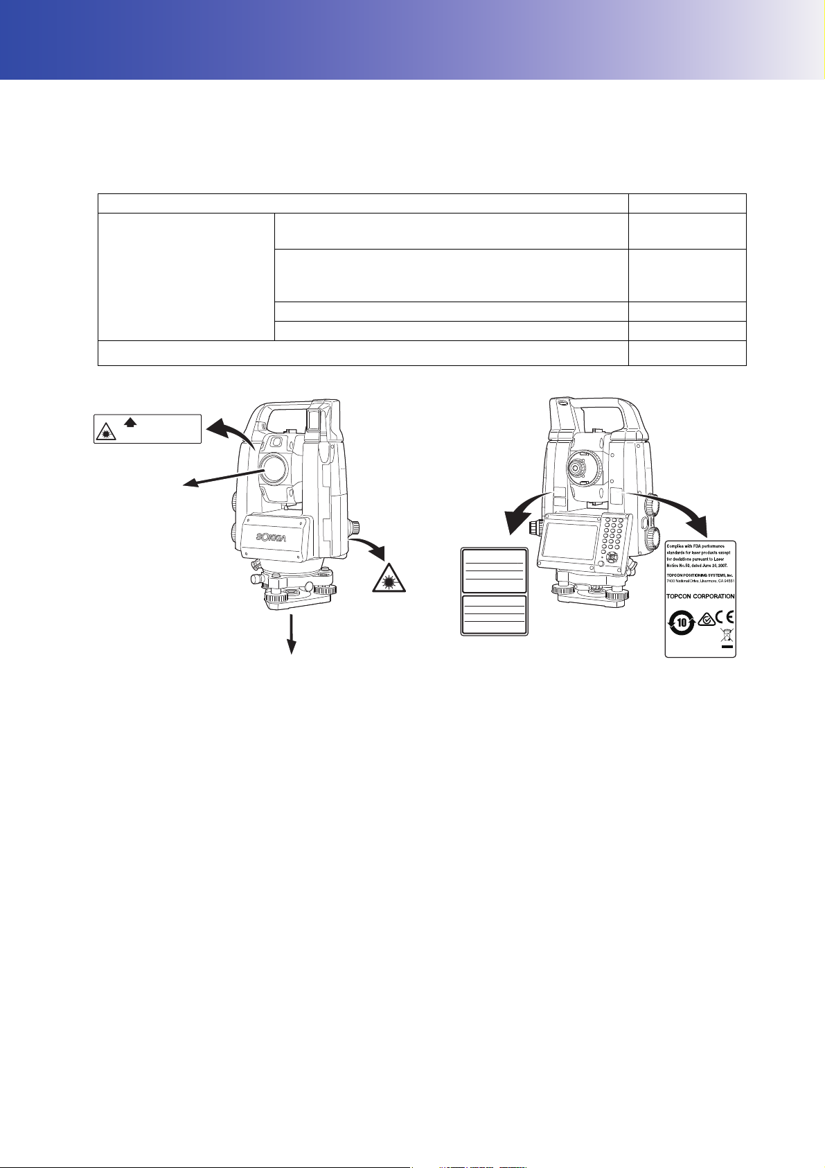
The instrument is classified as the following class of Laser Product according to IEC Standard Publication
60825-1 Ed.3.0: 2014 and United States Government Code of Federal Regulation FDA CDRH 21CFR Part
1040.10 and 1040.11 (Complies with FDA performance standards for laser products except for deviations
pursuant to Laser Notice No.50, dated June 24, 2007.)
Device Laser class
Light beam used for measurement
(When target (reflector) is set to N-prism.)
EDM device in objective
lens
Light beam used for measurement
(When target (reflector) is set to prism or reflective
sheet.)
Laser-pointer Class 3R
Light beam for Auto Pointing Class 1
Laser plummet (optional accessory)
Class 3R
Class 1
Class2
• EDM device is classified as Class 3R Laser Product when reflectorless measurement is selected. When
target (reflector) is set to prism or reflective sheet, the output is equivalent to the safer class 1.
Warning
• Use of controls or adjustments or performance of procedures other than those specified herein may result in
hazardous radiation exposure.
• Follow the safety instructions on the labels attached to the instrument as well as in this manual to ensure safe
use of this laser product.
• Never intentionally point the laser beam at another person. The laser beam is injurious to the eyes and skin.
If an eye injury is caused by exposure to the laser beam, seek immediate medical attention from a licensed
ophthalmologist.
• Do not look directly into the laser beam source or guide light source. Doing so could cause permanent eye
damage.
• Do not stare at the laser beam. Doing so could cause permanent eye damage.
• Never look at the laser beam through a telescope, binoculars or other optical instruments. Doing so could
cause permanent eye damage.
• Sight targets so that the laser beam does not stray from them.
7

3. LASER SAFETY INFORMATION
Caution
• Perform checks at start of work and periodic checks and adjustments with the laser beam emitted under
normal conditions.
• When the instrument is not being used, turn off the power and replace the lens cap.
• When disposing of the instrument, destroy the battery connector so that the laser beam cannot be emitted.
• Operate the instrument with due caution to avoid injuries that may be caused by the laser beam
unintentionally striking a person in the eye. Avoid setting the instrument at heights at which the path of the
laser beam may strike pedestrians or drivers at head height.
• Never point the laser beam at mirrors, windows or surfaces that are highly reflective. The reflected laser beam
could cause serious injury.
• Only those who have been received training as per the following items shall use this product.
• Read this manual for usage procedures for this product.
• Hazardous protection procedures (read this chapter).
• Requisite protective gear (read this chapter).
• Accident reporting procedures (stipulate procedures beforehand for transporting the injured and
contacting physicians in case there are laser induced injuries).
• Persons working within the range of the laser beam are advised to wear eye protection which corresponds to
the laser wavelength of the instrument being used. (OD2)
• Areas in which the laser is used should be posted with a standard laser warning sign.
• When using the laser-pointer function, be sure to turn OFF the output laser after distance measurement is
completed. Even if distance measurement is canceled, the laser-pointer function is still operating and the
laser beam continues to be emitted.
8
4. PRODUCT OUTLINE
11
12
13
14
9
8
3
4
5
6
7
1
2
10
25
28
29
26
30
31
33
32
13
10
21
23
22
17
20
19
24
15
16
18
27
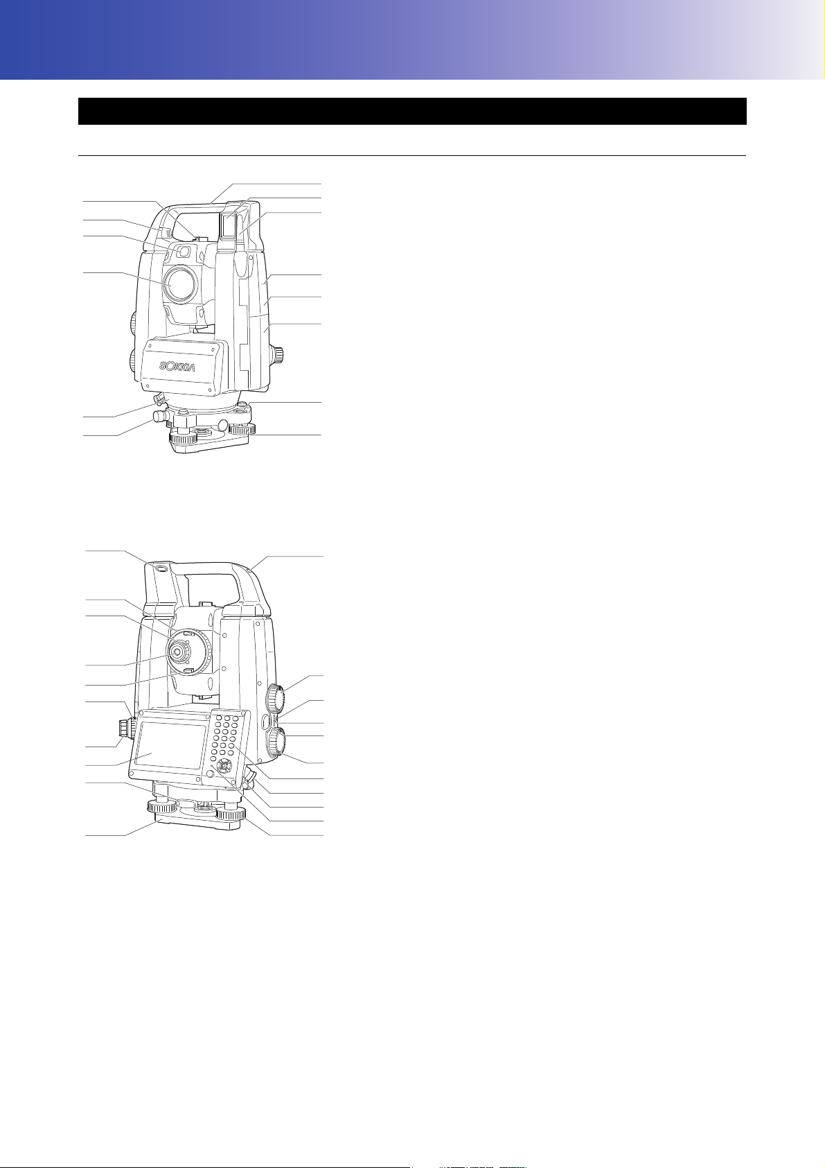
4.1 Parts of the Instrument
Parts and functions of the instrument
1 Handle
2 Beam detector for Remote Controller
3 Wireless antenna
4 Instrument height mark
5 External interface hatch
6 Battery cover
7 Circular level
8 Circular level adjusting screws
9 Tribrach locking screw
10 Luminance sensor
11 Objective lens (Includes " Laser-pointer function")
12 Guide light
13 Attach/detaching slider/button
14 Sighting collimator
(Auto Tracking model only)
"9. CONNECTING TO EXTERNAL DEVICES"
(Handle locking screw for Standard Handle)
"4.1 Parts of the Instrument Detaching/attaching the
RC Handle (Auto Tracking model)"
"4.1 Parts of the Instrument Detaching/attaching the
Standard Handle (Auto Pointing model)"
15 Tubular compass slot
16 Vertical Jog
17 Horizontal Jog
18 Power key
19 Speaker
20 Trigger key
21 Keyboard
"5.2 Display Functions"
22 Serial / External power source connector
23 Stylus (pen)
24 Levelling foot screw
25 Base plate
26 Tribrach clamp
27 Display unit
28 Optical plummet eyepiece
29 Optical plummet focussing ring
30 Telescope knob
31 Telescope eyepiece
32 Telescope eyepiece screw
33 Telescope focussing ring
Instrument height mark
The height of the instrument is as follows:
• 192.5mm (from tribrach mounting surface to this mark)
• 236mm (from tribrach plate to this mark)
"Instrument height" is input when setting instrument station data and is the height from the surveying point
(where the instrument is mounted) to this mark.
Laser-pointer function
A target can be sighted with a red laser beam in dark locations without the use of the telescope.
9
4. PRODUCT OUTLINE
redredgreengreengreen red
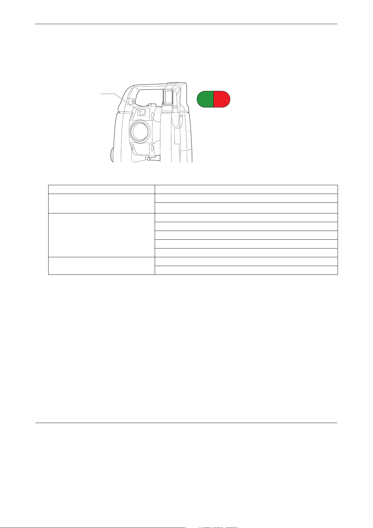
Guide light
(When seen from the objective lens side
while the instrument is in the Face 1 state)
Guide light
Setting-out measurement etc. can be carried out effectively using the guide light. The guide light is
composed of a light that is divided into green and red sections. A poleman can ascertain the present
position by checking the guide light color.
Guide light status
Light status Meaning
Slow flashing
(Red and green simultaneously)
Fast flashing
(Red and green simultaneously)
Green and red alternate flashing Distance measurement error (no signal, sighting error)
Waiting
Search error (error screen only)
Searching in progress
Measuring (continuous measurement)
Returned signal checking in progress
Auto Tracking in progress (Auto Tracking model only)
Auto Tracking in predicted direction (Auto Tracking model only)
"Prism wait"
"12.2 Using the Guide Light in Distance Measurement", "15.1 Using the Guide Light in Setting-out
Measurement"
Sighting collimator
Use sighting collimator to aim the instrument in the direction of the measurement point.
Turn the instrument until the apex of the triangle in the sighting collimator is aligned with the target. A circle
surrounds the triangle to make it easier to locate.
Vertical and Horizontal Jogs
The instrument and telescope can be rotated manually by hand or, for more precise adjustments, by
turning the vertical and horizontal Jogs.
Trigger key
When the Trigger key is pressed the instrument carries out the operation indicated by the orange
Operating icon on the screen. This allows the user to continue operation without having to return to the
display to press Operating icons.
Wireless antenna
The wireless antenna allows communication via wireless technologies.
• Handle the antenna with care. The antenna may be damaged if struck during operation or while being stored
in the carrying case.
10
4. PRODUCT OUTLINE
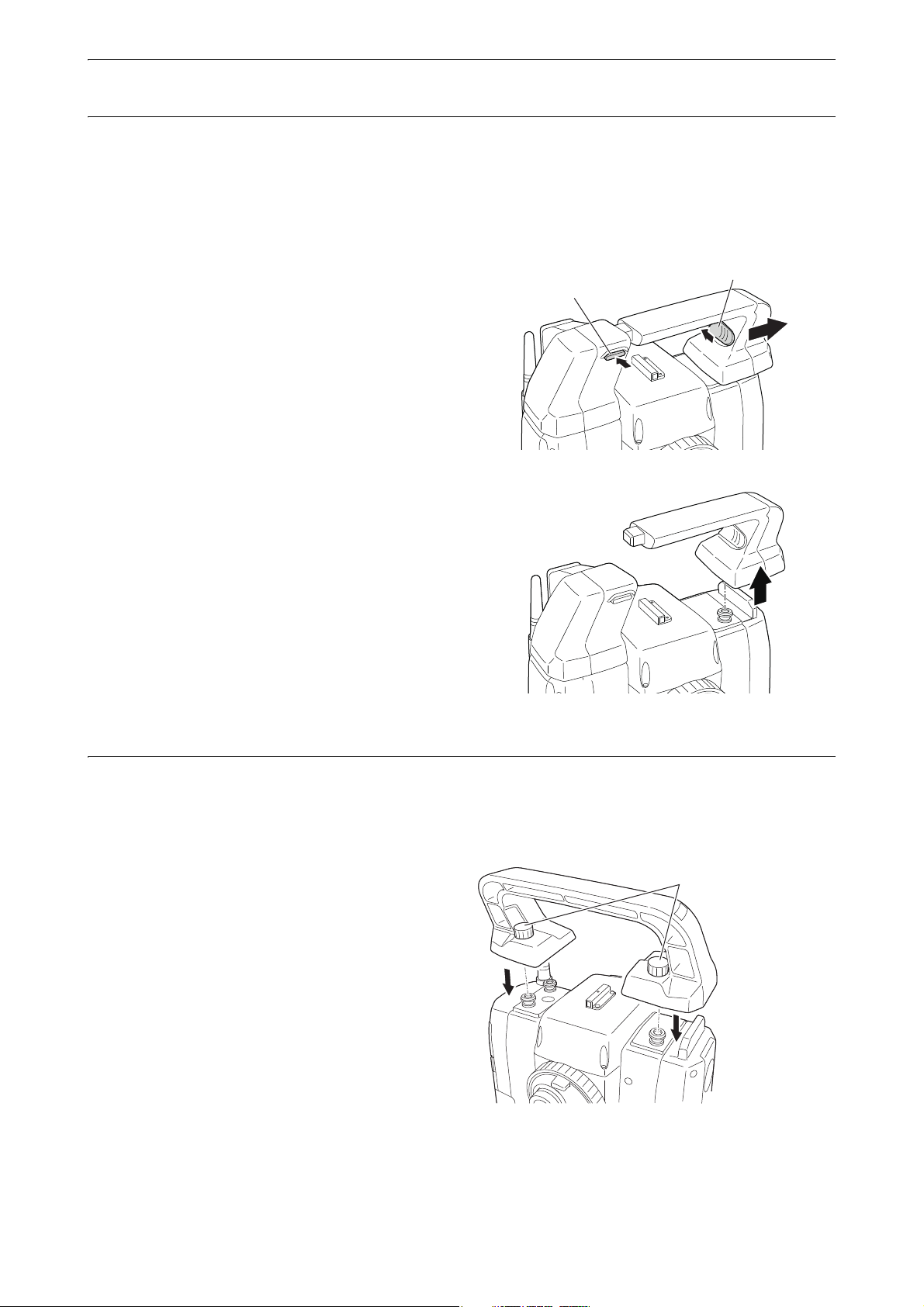
Attach/detaching button
Attach/detaching slider
Handle rocking screws
Detaching/attaching the RC Handle (Auto Tracking model)
The carrying handle can be removed from the instrument when the prism is located at the zenith etc.
• Never touch the beam detector. The ability of the system to perform Turning may be adversely affected. If the
beam detector is dirty, carefully wipe it with the silicon cloth.
1. Press the attach/detaching button and then move
the handle to the right while sliding the attach/
detaching slider to the direction indicated in the
arrow.
2. Along with the step 1, lift it up to detach.
Detaching/attaching the Standard Handle (Auto Pointing model)
The carrying handle can be removed from the instrument when the prism is located at the zenith etc.
1. To remove it, loosen the handle rocking screws.
2. To attache the handle, position the handle as
shown, tighten the 2 handle rocking screws
securely.
11

Detaching the instrument from the tribrach
(1)
(2)
(3)
1. Loosen the tribrach locking screw by turning 2 or
3 rotations in the counterclockwise direction.
2. Turn the tribrach clamp counterclockwise to
loosen.
3. Lift the instrument to detach.
Attaching the instrument to the tribrach
1. Check that the tribrach locking screw has been
loosened.
2. Align (1) and (2) and lower the instrument onto the
tribrach.
3. Turn the tribrach clamp clockwise to tighten.
4. PRODUCT OUTLINE
4. Turn the tribrach locking screw (3) clockwise to
tighten.
• Always fully tighten the tribrach locking screw to
reduce adverse effects of motor operation on
accuracy and ensure optimal results.
12
4. PRODUCT OUTLINE
>OK@
^PRG`
^ۻ`
^ESC`
^ۻ`
^PRG`
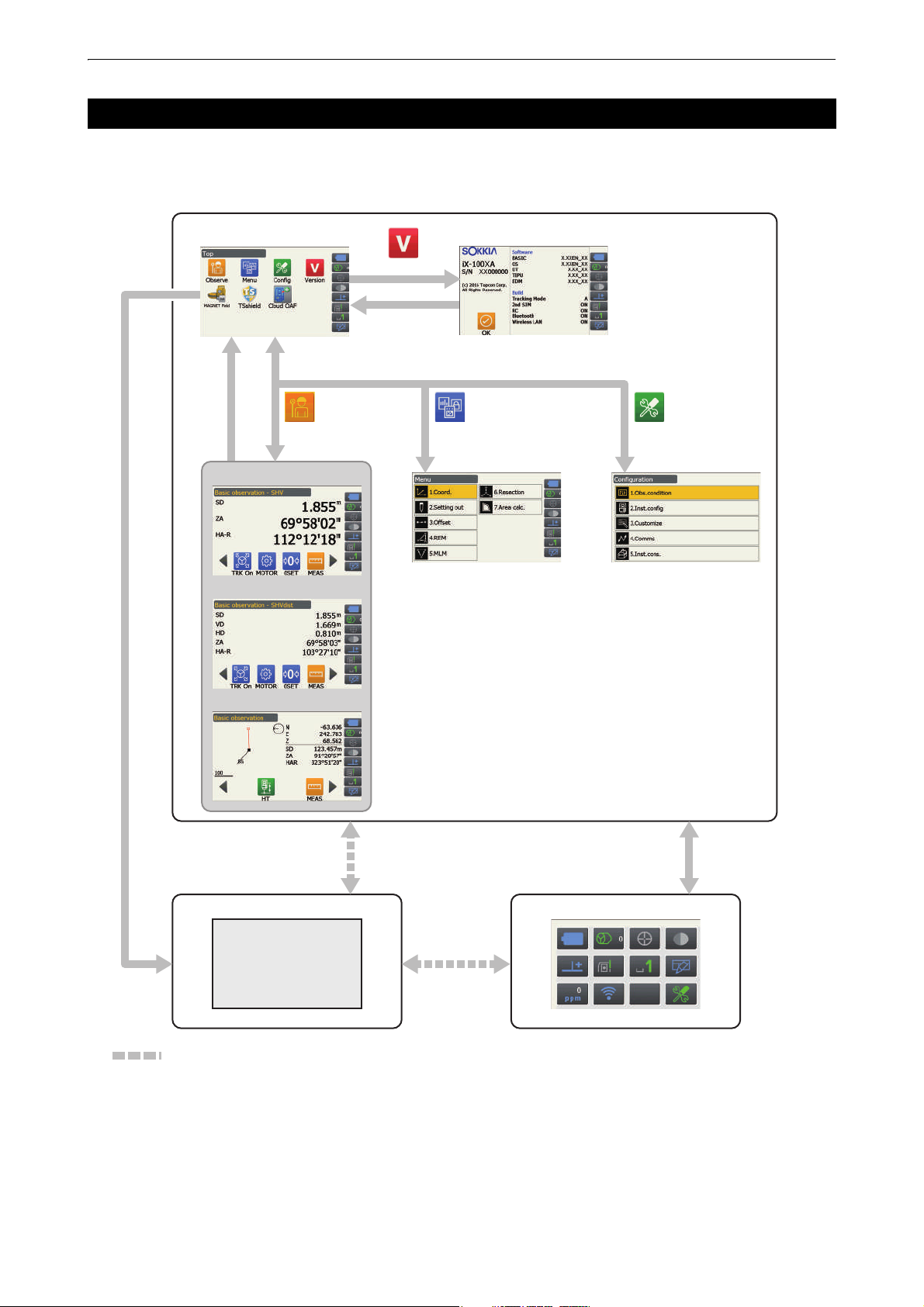
Program screen
OBSERVE MENU
Version
CONFIG
SHV display
Distance display
Graphic display
Version display mode
●Program mode ●Starkey mode
●Basic mode
Observation mode
(Display switchable)
Menu mode
Top menu
Config mode
Program
activate
icons
:Available only when a program is activated.
*1
*1: The previous screen {PRG} is pressed is recovered. However one of the observation screens is recovered just after
a program is activated.
4.2 Mode Structure
The diagram below describes the different modes of the instrument and key operations for navigating between
them.
• Switching between modes is not possible during distance measurement.
• Do not switch between modes by {PRG} or not turn OFF the power just after pressing {PRG} (when a
program is activated or quit).
13

4. PRODUCT OUTLINE
• "TSshield" and "Cloud OAF" may not be installed on the instrument depending on the country or the area
where the instrument is purchased.
4.3 Bluetooth Wireless Technology/Wireless LAN
• Bluetooth/Wireless LAN function may not be built in depending on telecommunications regulations of the
country or the area where the instrument is purchased. Contact your local dealer for the details.
• Use of this technology must be authorized according to telecommunications regulations of the country where
the instrument is being used. Contact your local dealer in advance.
"28. REGULATIONS"
• TOPCON CORPORATION is not liable for the content of any transmission nor any content related thereto.
When communicating important data, run tests beforehand to ascertain that communication is operating
normally.
• Do not divulge the content of any transmission to any third party.
Radio interference when using Bluetooth technology/Wireless LAN
Bluetooth/Wireless LAN communication with the iX uses the 2.4 GHz frequency band. This is the same band
used by the devices described below.
• Industrial, scientific, and medical (ISM) equipment such as microwaves and pacemakers.
• portable premises radio equipment (license required) used in factory production lines etc.
• portable specified low-power radio equipment (license-exempt)
• IEEE802.11b/IEEE802.11g/IEEE802.11n standard wireless LAN devices (When using Bluetooth function)
• The above devices use the same frequency band as Bluetooth communications. As a result, using the iX
within proximity to the above devices may result in interference causing communication failure or reduction
of transmission speed.
• Bluetooth devices (when Wireless LAN function)
Although a radio station license is not required for this instrument, bear in mind the following points when using
Bluetooth technology for communication.
Regarding portable premises radio equipment and portable specified low-power radio equipment:
• Before starting transmission, check that operation will not take place within the vicinity of portable premises
radio equipment or specified low-power radio equipment.
• In the case that the instrument causes radio interference with portable premises radio equipment,
terminate the connection immediately and take measures to prevent further interference (e.g. connect
using an interface cable).
• In the case that the instrument causes radio interference with portable specified low-power radio
equipment, contact your local dealer.
When using Bluetooth function in proximity to IEEE802.11b/IEEE802.11g/IEEE802.11n standard
wireless LAN devices, turn off all wireless LAN devices not being used and vice versa.
• Interference may result, causing transmission speed to slow or even disrupting the connection completely.
Turn off all devices not being used.
Do not use the iX in proximity to microwaves.
• Microwave ovens can cause significant interference resulting in communication failure. Perform
communication at a distance of 3m or more from microwave ovens.
14

4. PRODUCT OUTLINE
Refrain from using the iX in proximity to televisions and radios.
• Televisions and radios use a different frequency band to Bluetooth/Wireless LAN communications.
However, even if the iX is used within proximity to the above equipment with no adverse effects with regard
to Bluetooth/Wireless LAN communication, moving a Bluetooth/Wireless LAN compatible device
(including the iX) closer to said equipment may result in electronic noise in sound or images, adversely
affecting the performance of televisions and radios.
Precautions regarding transmission
For best results
• The usable range becomes shorter when obstacles block the line of sight, or devices such as
PDAs or computers are used. Wood, glass and plastic will not impede communication but the usable range
becomes shorter. Moreover, wood, glass and plastic containing metal frames, plates, foil and other heat
shielding elements as well as coatings containing metallic powders may adversely affect Bluetooth
communication and concrete, reinforced concrete, and metal will render it impossible.
• Use a vinyl or plastic cover to protect the instrument from rain and moisture. Metallic materials should not
be used.
• The direction of the Bluetooth antenna can have adverse effects upon usable range.
Reduced range due to atmospheric conditions
• The radio waves used by the iX may be absorbed or scattered by rain, fog, and moisture from the human
body with the limit of usable range becoming lower as a result. Similarly, usable range may also shorten
when performing communication in wooded areas. Moreover, as wireless devices lose signal strength
when close to the ground, perform communication at as high a position as possible.
• TOPCON CORPORATION cannot guarantee full compatibility with all Bluetooth/Wireless LAN products on
the market.
15
5. BASIC OPERATION
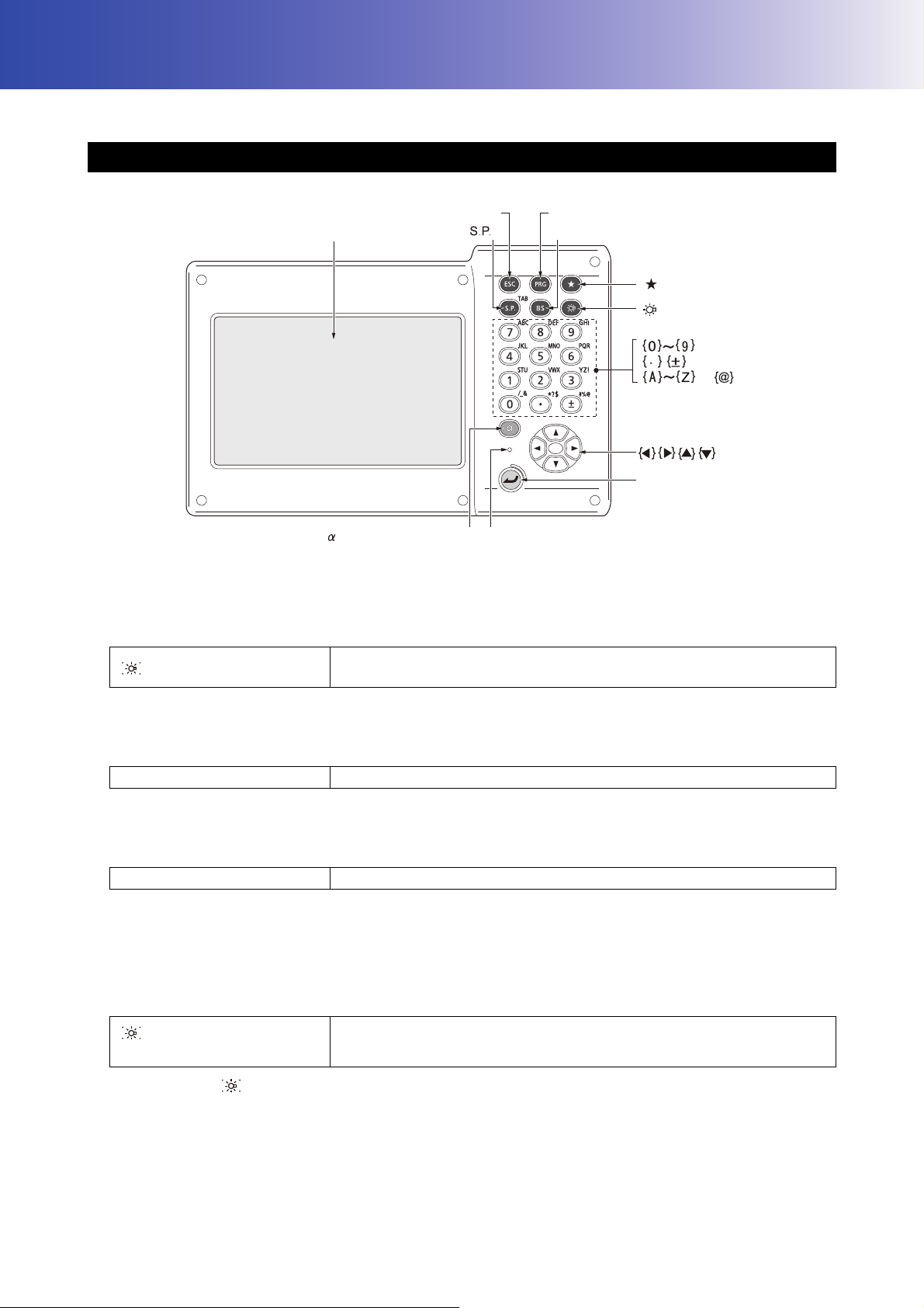
Display unit
Program mode
Starkey mode
Illumination
Switching input mode Luminance sensor{}
{ }
PRG
{ }
{ }
Enter
}
{ }
B.S.
{
to
{ESC}
{ }
Learn basic key operations here before you read each measurement procedure.
5.1 Basic Key Operation
Power ON/OFF
"8. POWER ON/OFF"
Lighting up the reticle/keys and selecting screen backlight brightness
{}
Switches the reticle illumination and key light On/Off (When Key light is
On, backlight brigthtness goes down)
Brightness level: "19.7 Instrument Conditions - Instrument"
Switching to Starkey mode
{
★ }
Switches to Starkey mode/previous screen
"5.4 Starkey Mode"
Switching to Program mode
{PRG} Switches to Program mode/Basic mode
• Do not switch between modes by {PRG} or not turn OFF the power just after pressing {PRG} (when a
program is activated or quit).
Switching the Laser-pointer/Guide light ON/OFF
{} (Press and hold until a
beep sounds
)
Turn ON/OFF the laser-pointer/guide light
"Switching {} function: 19.7 Instrument Conditions - Instrument"
• Changes can also be made by tapping the icon on Status icon or in Starkey mode.
"5.2 Display Functions Status icons", "5.4 Starkey Mode"
16

Inputting letters/figures
5. BASIC OPERATION
{α}
{α} + {
}
Switch numerals/alphabetic characters (upper case)/alphabetic
characters (lower case)
Display/hide <Input Panel>
Input numeral or symbol printed above the key (during numeric input
{0} to {9}
mode)
Input alphabetic character in the order they are listed (in alphabetic input
mode)
{.}
{
±}
{ESC}
{α} + {S.P}
{B.S.}
{S.P.}
{}/{}
{
}/{}
{Enter}
Input a decimal point (during numeric input mode)
Input code (in alphabetic input mode)
Input a plus or minus sign (during numeric input mode)
Input code (in alphabetic input mode)
Cancel the input data
Shift to the next item
Delete a character on the left.
Input a blank space (increments by 1 when setting the date and time)
Move the cursor left/right
Move the cursor up/down
Select/accept input word/value
Inputting rule and inputting special characters: "5.3 Inputting Characters using the Input Panel"
Selecting options
{
}/{}
{}/{}
{α} + {S.P}
{S.P.}
{Enter}
Others
Move the cursor/selection item up/down
Move the cursor/selection item left/right or select other option
Shift to the next item
Display other options
Select/accept the option
{ESC} Return to previous screen
17
5. BASIC OPERATION
Tap the screen title
to display Popup
Operating icons
Switching Operating icons
5.2 Display Functions
Screens can be operated using the keys on the keyboard or the touch panel. The touch panel can be operated
using either the stylus pen provided or your fingers.
It is also possible to de-activate the touch panel temporarily.
• Do not scratch the display or use any sharp implement other than the stylus pen to operate the touch panel.
Using the stylus
The stylus pen can be used to select menus and buttons on the screen and operate the scroll bar.
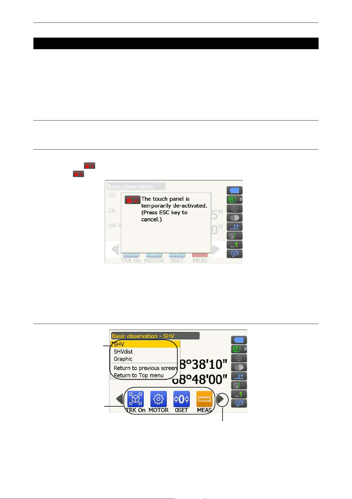
Temporarily de-activating the touch panel
The touch panel can be temporarily de-activated. This is especially useful when cleaning the display.
To de-activate, tap on the Status icon. The screen below is displayed.
Allocating : "19.13 Changing Starkey Mode Icons"
The touch panel cannot be operated while the above message is displayed. Press {ESC} to cancel the
message and re-activate the touch panel.
• Keyboard operation is partially limited during the Temporarily de-activating the touch panel.
Displaying and operating screens
• Operating icon allocations, displayed items, and character sizes can all be changed in accordance with user
preferences.
"19. CHANGING THE SETTINGS"
18
5. BASIC OPERATION
Program activate
Mode switch icons
icons
Instrument name
Serial number
Functions on
your instrument
(1) Distance
(2) Vertical angle
(3) Horizontal angle
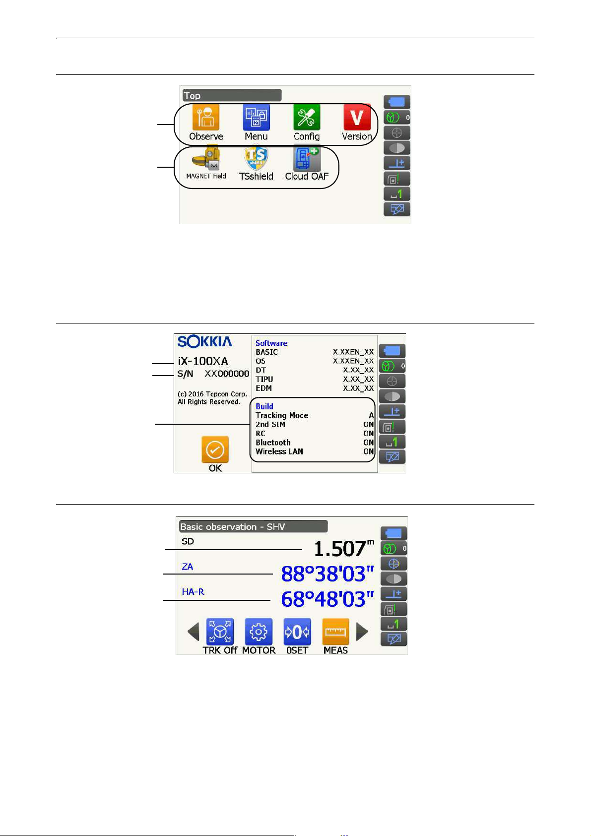
Top menu
• "TSshield" and "Cloud OAF" may not be installed depending on the country or the area where the instrument
is purchased.
• Only one program can be activated at a time. Icons whose background are gray cannot be selected.
Version display mode screen
Observation mode screen "SHV" display
(1) Distance
(2) Vertical angle
Display status can be switched between SD (slope distance)/HD (horizontal distance)/VD (vertical
distance).
"19.2 Observation Conditions - Dist"
The Vertical angle display can be switched between Zenith (Z=0°)/Horiz (H=0°)/Horiz (H=±90°)
To switch vertical angle/slope in %, press [ZA/%] when allocated to the Observation mode screen.
"19.1 Observation Conditions - Angle/Tilt"
19
5. BASIC OPERATION
Laser is emitted
Instrument station
Scale
(units: m)
Arrow indicates north as set backsight
Target point
The capitalized letter in the Operating icon indicates the currently selected mode.
Allocating [ZA/%]: "19.12 Allocating Operating Icons"
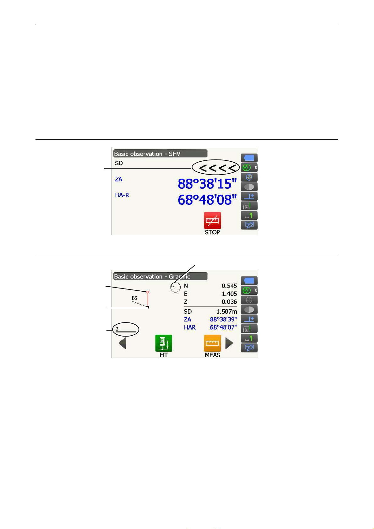
(3)Horizontal angle
Press [R/L] to switch the display status between HA-R (horizontal angle right)/HA-L (horizontal angle left).
The capitalized letter in the Operating icon indicates the currently selected mode.
Allocating [R/L]: "19.12 Allocating Operating Icons"
• Horizontal distance and height difference are also displayed in "SHVdist" display of Observation mode.
Measuring screen
Observation mode screen "Graphic" display
Following operations are available by switching Operating icons.
[CNFG] : In <Graphic configuration> the user can specify the orientation of the "graphic" display and
which point, target or station, to set at the center of the display.
[DEF.] : Returns to the original orientation display.
[ZoomIn]:Zooms in.
[ZoomOut]:Zooms out.
20
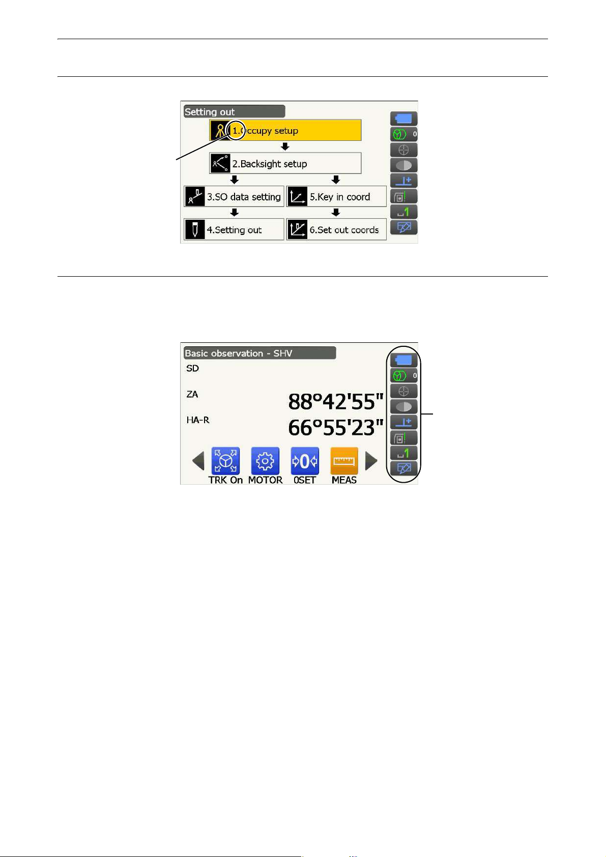
5. BASIC OPERATION
Number
Status icons
Selecting menus
To select a menu, tap the touch panel or press the relevant number key.
Status icons
Indicate the current status of the instrument.
Tapping icons will switch between the relevant options for that item.
Tapping and holding will display a list of all available options for that item and, in certain cases, a link to the
configuration screen for that item.
Allocation of the icons of the Status icon corresponds with that of Starkey mode.
About icons: "5.4 Starkey Mode"
21
5. BASIC OPERATION
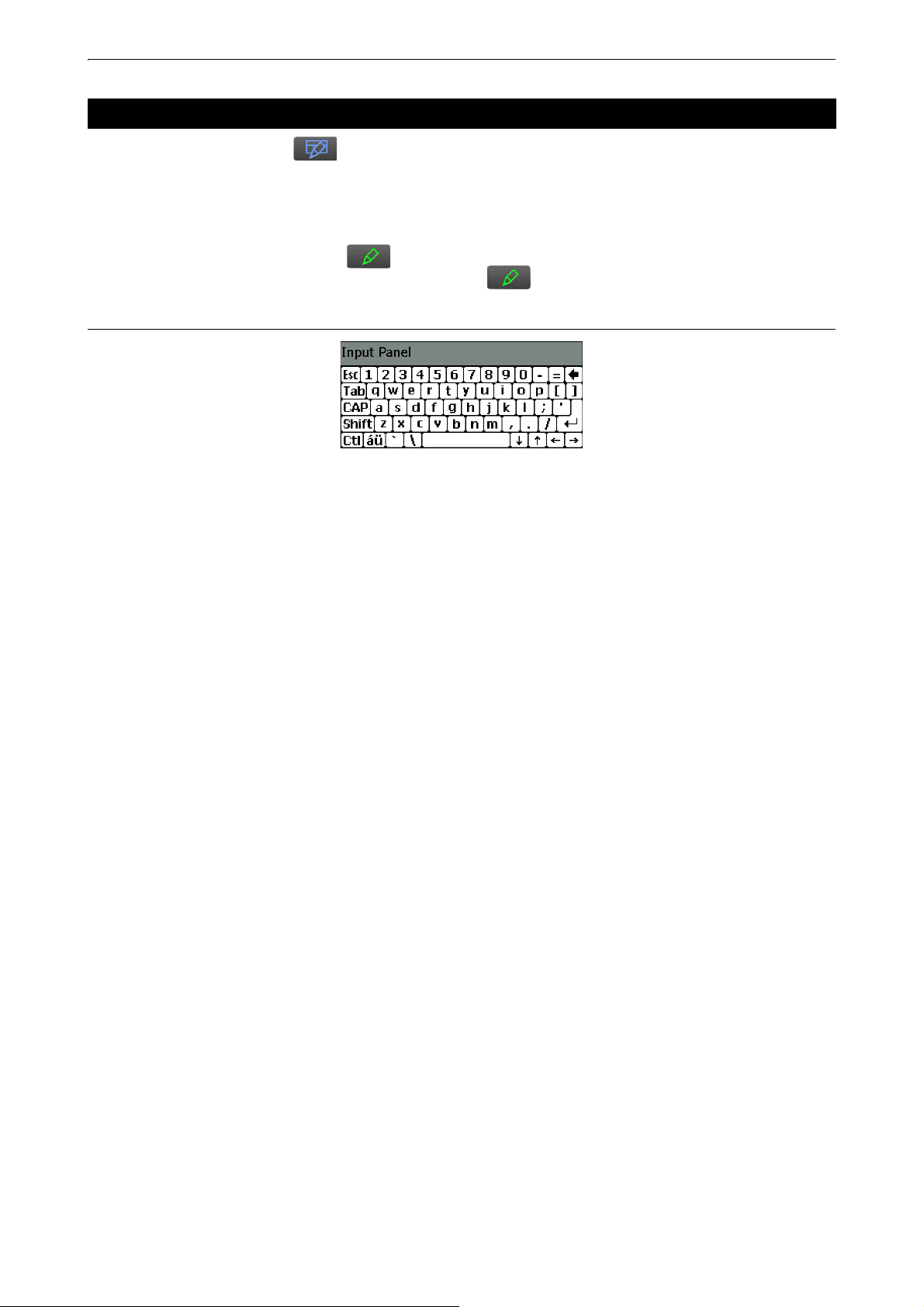
5.3 Inputting Characters using the Input Panel
To d i s p l a y <Input Panel>, tap of Status icon/Starkey mode or while pressing {α} press {}. This
keyboard can be used to input numeric and alphabetic characters as well as symbols. Tap the icon again to
close.
• When <Input Panel> is covering the icon of the Status icon, use the stylus pen to drag the input panel
to another part of the screen so that you can access the icon.
Input panel
Esc : Deletes all input characters
Tab : Moves the cursor to the next text box
CAP : Alternates between upper and lower case alphabetic characters and numbers/symbols
Shift : Alternates between upper and lower case alphabetic characters and numbers/symbols. Is
canceled after inputting a single character.
Ctl : No function
Del/ : Delete the character to the left/right or deletes the entire text in the active section
←→ : Move the cursor left/right
ENT : Accept input characters
Space : Input a blank space
áü : Accesses further Latin/Germanic characters/symbols. Is canceled after inputting a single
character.
22
5. BASIC OPERATION
(1) (2) (3) (4)
(5) (6) (7) (8)
(9)(10) (11)
(12) (13)
when instrument was shipped.
12 and 13 are not allocated
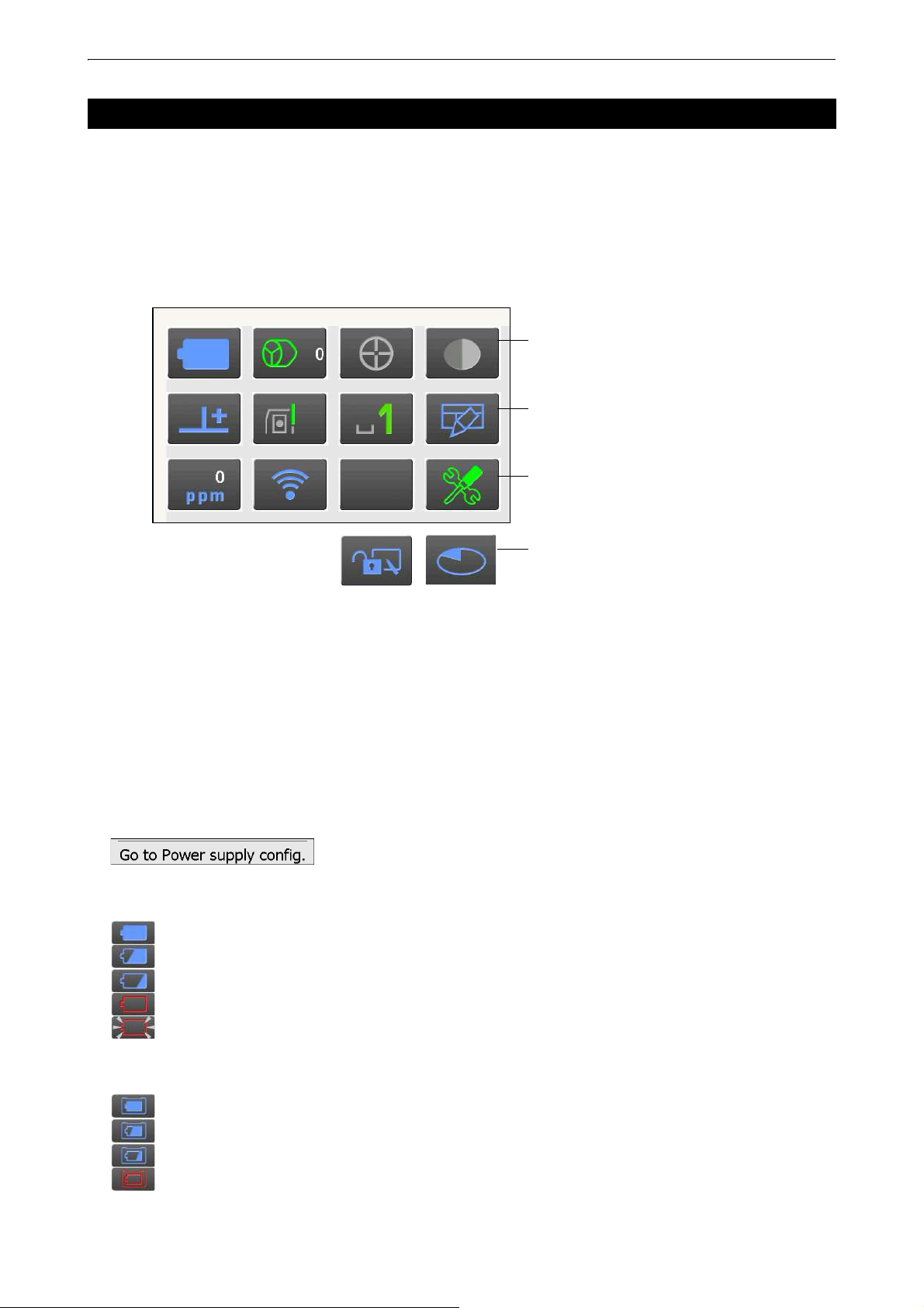
5.4 Starkey Mode
Via Starkey mode, you can jump from each Basic mode screen to the screen of checking/changing the various
settings directly. Press starkey {
same way with Status icon.
• 12 icons allocated in Starkey mode and the above 8 icons correspond with that Status icon
• Allocation of the icons can be changed.
★ } to enter Starkey mode. Each icon can be tapped or pressed and hold in the
Changing allocation of Starkey mode: "19.13 Changing Starkey Mode Icons"
Indicates the current status of the instrument.
Tapping icons will switch between the relevant options for that item. Tapping and holding will display a list of all
available options for that item and, in certain cases, a link to the configuration screen for that item.
Details of each icon are described below. (The numbers correspond to above icons).
(1) Battery icon
Remaining battery power indicator (Temperature = 20°C, EDM on).
The remaining battery power displayed when distance measurement is in progress may differ to that
displayed at other times.
You can jump to the Power config. screen.
"19.6 Instrument Conditions - Power"
When using standard battery (BDC70)
: Level 3 Full power
: Level 2 Plenty of power remains.
: Level 1 Half or less power remains.
: Level 0 Little power remains. Prepare a replacement battery. (Flashes red and black)
: No power Stop operation and charge the battery. (Red display in the center of the screen)
"6.1 Battery Charging"
When using external battery (BDC60A/61A)
: Level 3 Full power
: Level 2 Plenty of power remains.
: Level 1 Half or less power remains.
: Level 0 Little power remains. Prepare a replacement battery.
"6.1 Battery Charging"
23
5. BASIC OPERATION
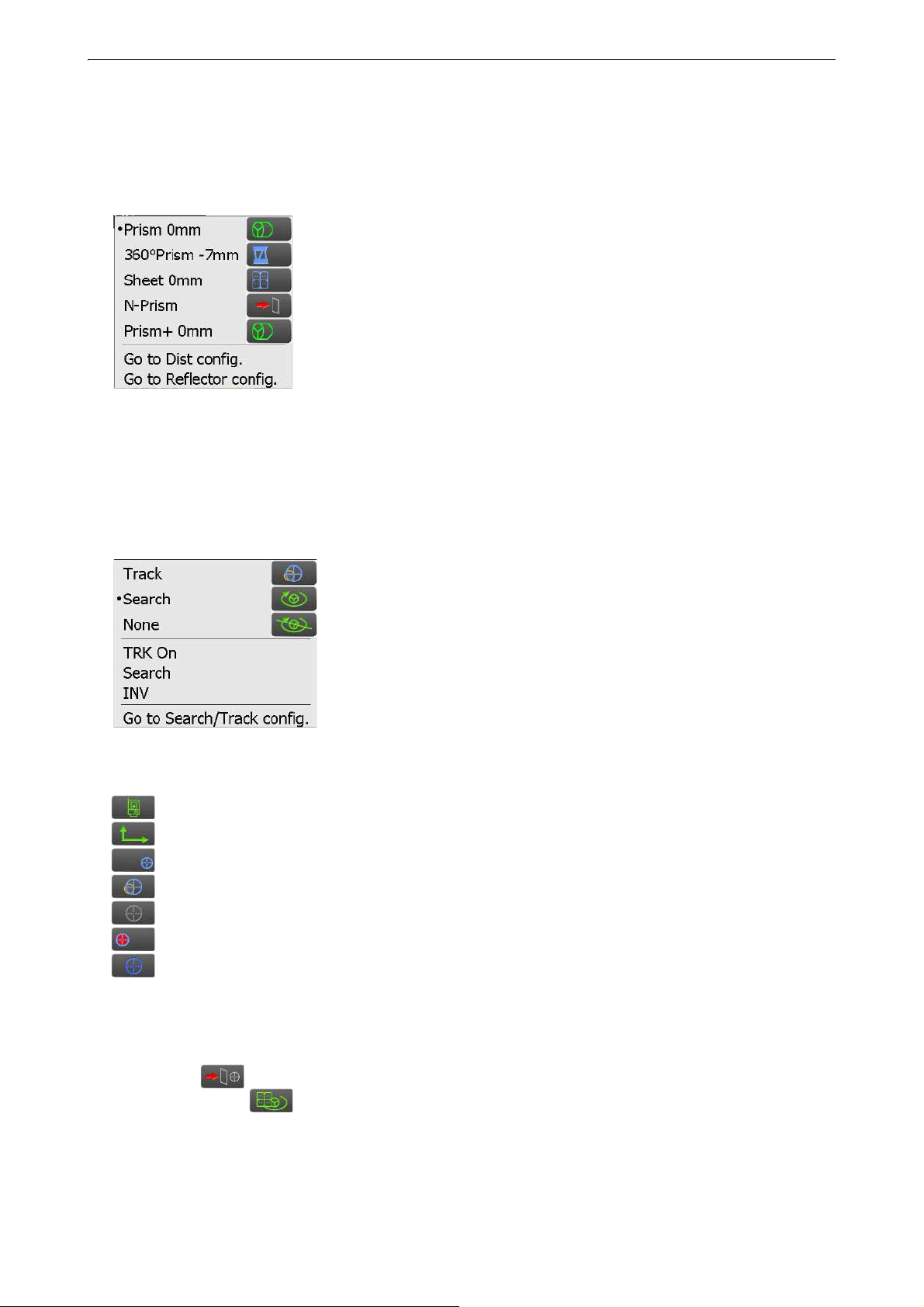
(2) Target type icon
Selection of target type and configuration of prism constant correction value.
You can jump to the Distance config. or Reflector config. screen.
"19.2 Observation Conditions - Dist"
"19.3 Observation Conditions - Reflector (Target)"
: Prism (0 mm)
: 360° prism (-7 mm)
: Sheet (0 mm)
: N-Prism
: "+" indicates a target used with an external device or in a program installed
in the Program mode.
(3) Motor icon
Configuration of Auto Pointing/Auto Tracking status. The display may change slightly depending on the
target type selected. Auto Tracking items are only relevant to Auto Tracking models and are not available
for Auto Pointing models.
You can jump to the Search/Track config. screen.
"10.1 Auto Pointing and Auto Tracking Settings"
: Perform Auto Pointing and Tracking when measuring the distance
: Perform only Auto Pointing when measuring the distance
: Measure the distance only
: Start Auto Tracking. "TRK Off" is displayed when performing Auto
Tracking or when in "Prism wait" status. Tap to quit Auto Tracking.
: Begin searching
: Rotates the instrument 180°
One of the following icons will be displayed while the motor is in operation to indicate the current status of
the instrument.
:Rotating
: Rotating at fixed velocity
: Searching/Searching after target lost during Auto Tracking
: Auto Tracking in progress
: Auto Tracking idle (when Auto Tracking set)
: Auto Tracking in predicted direction
: Waiting for prism during Auto Tracking
Predicted direction and waiting for prism: "10.1 Auto Pointing and Auto Tracking Settings Lost Prism"
• Auto Tracking and Auto Pointing cannot be performed when "Reflectorless" has been selected as the
target type ( will be displayed). Auto Tracking cannot be performed when "Sheet" has been selected
as the target type ( will be displayed).
• An arrow indicating turn direction will be displayed when the instrument is rotating at a fixed velocity.
24

5. BASIC OPERATION
(4) Laser-pointer/guide light icon
Selection of laser-pointer/guide light status.
Switching the laser-pointer/guide light ON/OFF: "5.1 Basic Key Operation"
You can jump to the Instrument config. screen.
"19.7 Instrument Conditions - Instrument"
: Guide light ON
: Guide light OFF
: Laser-pointer ON
: Laser-pointer OFF
• The laser-pointer will be automatically switched OFF during distance measurement.
(5) Tilt angle compensation icon
The vertical and horizontal angles are automatically compensated for small tilt errors using the dual-axis tilt
sensor.
Selection of tilt function condition.
You can display <Tilt> or jump to the Angle/tilt config. screen.
<Tilt>: "7.2 Levelling"
Setting of tilt angle compensation: "19.1 Observation Conditions - Angle/Tilt"
: Horizontal and vertical tilt angles compensated (blue)
: No compensation
: Only vertical tilt angle compensated (green)
• is displayed when the instrument is out of level.
(6) Communication status with external devices icon
Selection of communication method with external devices.
You can jump to the Communication config. screen.
Setting of RS232C communication: "9.3 Connection via RS232C Cable"
Setting of Bluetooth communication: "9.1 Wireless Communication using Bluetooth Technology"
: Connection via RS232C cable
: Connection via Bluetooth wireless technology
Connection status to external devices is displayed as follows.
i) Connection via Bluetooth wireless technology
: Connecting
: Canceling connection
: (Antenna is moving) Inquiring about other Bluetooth devices
: (Antenna is stationary) Communication settings in progress/Preparing for communication
(Instrument just powered ON etc.)
: Connection error (icon flashes)
25
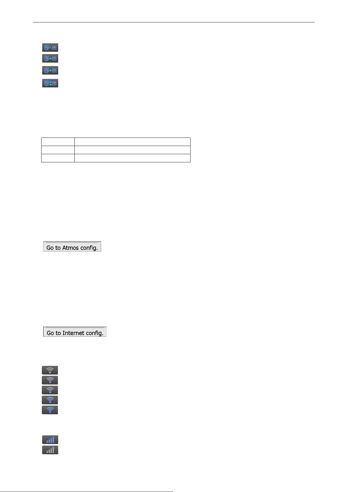
ii) Connection via RS232C cable
: RS232C is selected
: Sending data from a data collector to iX
: Sending data from iX to a data collector
: Exchanging data in both directions between iX and a data collector
• A red arrow indicates that data transmission has failed and data needs to be sent again.
(7) Input mode icon
Selection of input mode
_1 Inputting numbers and symbols
_a Inputting lower case alphabetic characters
_A Inputting upper case alphabetic characters
"5.1 Basic Key Operation Inputting letters/figures"
(8) Input panel icon
"5.3 Inputting Characters using the Input Panel"
5. BASIC OPERATION
(9) PPM setting icon
Current atmospheric correction factor setting is displayed.
You can jump to the Atmos config. screen.
"19.4 Observation Conditions - Atmosphere"
(10) Internet communication status
Connection status of internet communication is displayed.
You can jump to the Internet config. screen.
"9.4 Wireless LAN Settings and Communication"
"9.5 Cellular Settings and Communication"
Configuration of internet communication.
Connection status to a router is displayed as follows.
i) Wireless LAN connection
: Disconnected/Intensity of signal less than -91 (dBm)
: Intensity of signal -90 to -70(dBm)
: Intensity of signal -71 to -68(dBm)
: Intensity of signal -67 to -58(dBm)
: Intensity of signal more than -57 (dBm)
ii) Cellular connection
: Connected
: Disconnected
26
 Loading...