

Sokkia im-101, im-102, im-105, im-103 Operator's Manual
SURVEYING INSTRUMENTS
iM-100 series
intelligence Measurement Station
Class 3R Laser Product
OPERATOR'S MANUAL
1019174-01-A
HOW TO READ THIS MANUAL
Low temperature
seal
Thank you for selecting the iM-100 series.
• Please read this Operator’s manual carefully, before using this product.
• iM has a function to output data to a connected host computer. Command operations from a host computer
can also be performed. For details, refer to "Communication manual" and ask your local dealer.
• The specifications and general appearance of the instrument are subject to change without prior notice and
without obligation by TOPCON CORPORATION and may differ from those appearing in this manual.
• The content of this manual is subject to change without notice.
• Some of the diagrams shown in this manual may be simplified for easier understanding.
• Always keep this manual in a convenient location and read it when necessary.
• This manual is protected by copyright and all rights are reserved by TOPCON CORPORATION.
• Except as permitted by Copyright law, this manual may not be copied, and no part of this manual may be
reproduced in any form or by any means.
• This manual may not be modified, adapted or otherwise used for the production of derivative works.
Symbols
The following conventions are used in this manual.
: Indicates precautions and important items which should be read before operations.
: Indicates the chapter title to refer to for additional information.
: Indicates supplementary explanation.
: Indicates an explanation for a particular term or operation.
[MEAS] etc. : Indicates Operation icons on the display and window dialog buttons.
{ESC} etc. : Indicates keys on the operation panel.
<Screen title> etc.: Indicates screen titles.
Notes regarding manual style
• Except where stated, “iM” means iM-100 series in this manual.
• Except where stated, instrument with display on both sides is used for illustration.
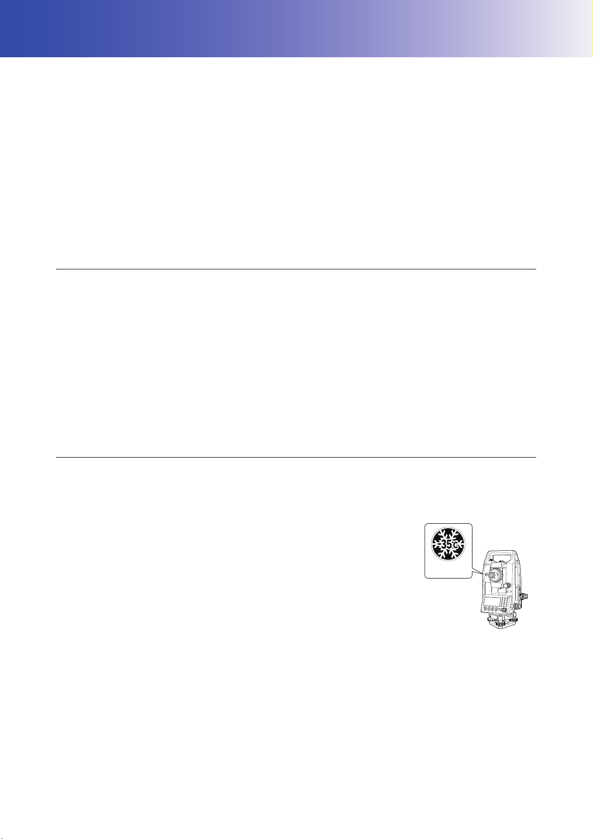
• The iM Series is available in "standard" and "Low Temperature" models. Users with a "Low Temperature
Model" should read the additional precautions specific to use under low temperatures.
• Low Temperature Model
Low Temperature Models display the seal shown at right.
• Do not remove the Low Temperature Model seal from the instrument. This
seal is used for model recognition by our engineers during maintenance.
• Screens appearing in this manual are based on the setting "Dist. reso: 1 mm". When "Dist. reso: 0.1 mm" is
selected, the number of decimal places for distance and atmospheric condition input values will be increased
by one.
"33. CHANGING THE SETTINGS"
• Location of Operation icons in screens used in procedures is based on the factory setting. It is possible to
change the allocation of Operation icons.
"33. CHANGING THE SETTINGS"
• Except where stated, instrument with RC Handle is used for illustration.
• Learn basic operations in "4. PRODUCT OUTLINE" and "5. BASIC OPERATION" before you read each
measurement procedure. For selecting options and inputting figures, see "5.1 Basic Key Operation".
i

• Measurement procedures are based on continuous measurement. Some information about procedures when
Li-ion
S Li-ion
This is the mark of the Japan Surveying Instruments Manufacturers Association.
other measurement options are selected can be found in “Note” ().
• KODAK is a registered trademark of Eastman Kodak Company.
• Bluetooth
®
is a registered trademark of Bluetooth SIG, Inc.
• All other company and product names featured in this manual are trademarks or registered trademarks of
each respective organization.
ii

CONTENTS
1. PRECAUTIONS FOR SAFE OPERATION ................................................................... 1
2. PRECAUTIONS .............................................................................................................4
3. LASER SAFETY INFORMATION .................................................................................. 7
4. PRODUCT OUTLINE .................................................................................................... 9
4.1 Parts of the Instrument ......................................................................................... 9
4.2 Mode Structure ................................................................................................... 12
4.3 Bluetooth Wireless Technology/Wireless LAN ................................................... 13
5. BASIC OPERATION ....................................................................................................15
5.1 Basic Key Operation ...........................................................................................15
5.2 Display Functions ............................................................................................... 18
5.3 Starkey Mode ..................................................................................................... 20
6. USING THE BATTERY ............................................................................................... 21
6.1 Battery Charging .................................................................................................21
6.2 Installing/Removing the Battery .......................................................................... 22
7. SETTING UP THE INSTRUMENT .............................................................................. 23
7.1 Centering ............................................................................................................23
7.2 Levelling .............................................................................................................24
8. POWER ON/OFF ........................................................................................................ 26
9. CONNECTING TO EXTERNAL DEVICES .................................................................. 28
9.1 Wireless Communication using Bluetooth Technology ......................................28
9.2 Communication between the iM and Companion Device ................................... 30
9.3 Connection via RS232C Cable ........................................................................... 32
10. TARGET SIGHTING AND MEASUREMENT .............................................................. 33
10.1 Manually Sighting the Target .............................................................................. 33
11. ANGLE MEASUREMENT ........................................................................................... 34
11.1 Measuring the Horizontal Angle between Two Points (Horizontal Angle 0°) ...... 34
11.2 Setting the Horizontal Angle to a Required Value (Horizontal Angle Hold) ........ 35
11.3 Angle Measurement and Outputting the Data .................................................... 37
12. DISTANCE MEASUREMENT ..................................................................................... 38
12.1 Returned Signal Checking ..................................................................................38
12.2 Distance and Angle Measurement ..................................................................... 39
12.3 Recalling the Measured Data .............................................................................40
12.4 Distance Measurement and Outputting the Data ............................................... 40
12.5 Coordinate Measurement and Outputting the Data ............................................ 41
12.6 REM Measurement .............................................................................................42
13. COORDINATE MEASUREMENT ................................................................................ 44
13.1 Entering Instrument Station Data and Azimuth Angle ........................................ 44
13.2 Setting Instrument Station Coordinate with resection measurement .................. 49
14. COORDINATE MEASUREMENT ................................................................................ 58
15. SETTING-OUT MEASUREMENT ...............................................................................60
15.1 Coordinates Setting-out Measurement ............................................................... 60
15.2 Distance Setting-out Measurement .................................................................... 62
15.3 REM Setting-out Measurement .......................................................................... 64
16. SETTING-OUT LINE ................................................................................................... 65
16.1 Defining Baseline ................................................................................................ 65
16.2 Setting-out Line Point ......................................................................................... 68
16.3 Setting-out Line Line ...........................................................................................70
17. SETTING-OUT ARC ....................................................................................................72
17.1 Defining an Arc ................................................................................................... 72
17.2 Setting-out Arc ....................................................................................................77
18. POINT PROJECTION ................................................................................................. 79
iii

18.1 Defining Baseline ................................................................................................ 79
18.2 Point Projection .................................................................................................. 79
19. TOPOGRAPHY OBSERVATION ................................................................................81
19.1 Observation Setting ............................................................................................ 82
19.2 Observation ........................................................................................................83
20. OFFSET MEASUREMENT ......................................................................................... 86
20.1 Single-distance Offset Measurement ................................................................. 86
20.2 Angle Offset Measurement ................................................................................. 87
20.3 Two-distance Offset Measurement ..................................................................... 88
20.4 Plane Offset Measurement ................................................................................. 90
20.5 Column Offset Measurement .............................................................................. 92
21. MISSING LINE MEASUREMENT ............................................................................... 94
21.1 Measuring the Distance between 2 or more Points ............................................ 94
21.2 Changing the Starting Point ................................................................................ 97
22. SURFACE AREA CALCULATION .............................................................................. 99
23. INTERSECTIONS ..................................................................................................... 102
23.1 Intersections (Type A) ...................................................................................... 102
23.2 Intersections (Type B) ...................................................................................... 110
24. TRAVERSE ADJUSTMENT ...................................................................................... 113
25. ROUTE SURVEYING ................................................................................................118
25.1 Instrument Station Settings .............................................................................. 118
25.2 Straight Line Calculation ...................................................................................119
25.3 Circular Curve Calculation ................................................................................121
25.4 Spiral Curve ...................................................................................................... 122
25.5 Parabola ...........................................................................................................127
25.6 3 Point Calculation ............................................................................................130
25.7 Intersection Angle/Azimuth Angle Calculation .................................................. 132
25.8 Route Calculation ............................................................................................. 134
26. CROSS SECTION SURVEY ..................................................................................... 145
27. Point to Line MEASUREMENT ..................................................................................149
28. RECORDING DATA - TOPO MENU - ....................................................................... 152
28.1 Recording Instrument Station Data ..................................................................152
28.2 Recording Backsight Point ............................................................................... 154
28.3 Recording Angle Measurement Data ............................................................... 155
28.4 Recording Distance Measurement Data ........................................................... 156
28.5 Recording Coordinate Data ..............................................................................157
28.6 Recording Distance and Coordinate Data ........................................................158
28.7 Reviewing JOB Data ........................................................................................ 159
28.8 Recording Notes ............................................................................................... 159
28.9 Deleting Recorded JOB Data ........................................................................... 161
29. SELECTING/DELETING A JOB ................................................................................ 162
29.1 Selecting a JOB ................................................................................................ 162
29.2 Deleting a JOB ................................................................................................. 163
30. REGISTERING/DELETING DATA ............................................................................165
30.1 Registering/Deleting Known Point Data ...........................................................165
30.2 Registering/Deleting Codes .............................................................................. 168
30.3 Reviewing Known Point Data ...........................................................................168
30.4 Reviewing Codes ..............................................................................................170
31. OUTPUTTING JOB DATA .........................................................................................171
31.1 Outputting JOB Data to Host Computer ........................................................... 171
32. USING USB FLASH DRIVE ......................................................................................173
32.1 Inserting the USB flash drive ............................................................................173
iv

32.2 Selecting T type/S type ..................................................................................... 174
32.3 Storing JOB Data to USB flash drive ................................................................ 174
32.4 Loading Data in USB flash drive to the iM ........................................................ 176
32.5 Displaying and Editing Files ............................................................................. 177
32.6 Formatting the Selected External Memory Media ............................................ 178
33. CHANGING THE SETTINGS ....................................................................................179
33.1 Observation Conditions - Angle/Tilt .................................................................. 179
33.2 Observation Conditions - Dist ...........................................................................180
33.3 Observation Conditions - Reflector (Target) ..................................................... 182
33.4 Observation Conditions - Atmosphere .............................................................. 183
33.5 Observation Conditions - Other ........................................................................ 184
33.6 Instrument Conditions - Power ......................................................................... 185
33.7 Instrument Conditions - Instrument ..................................................................186
33.8 Instrument Conditions - Unit .............................................................................187
33.9 Instrument Conditions - Password ....................................................................188
33.10TSshield ............................................................................................................189
33.11Instrument Conditions - Date and Time ............................................................ 189
33.12Allocating Key Functions ..................................................................................190
33.13Restoring Default Settings ................................................................................ 192
34. WARNING AND ERROR MESSAGES ..................................................................... 194
35. CHECKS AND ADJUSTMENTS ............................................................................... 198
35.1 Circular Level ....................................................................................................198
35.2 Tilt Sensor ........................................................................................................ 198
35.3 Reticle ...............................................................................................................201
35.4 Collimation ........................................................................................................201
35.5 Optical Plummet ............................................................................................... 202
35.6 Additive Distance Constant ..............................................................................204
35.7 Laser Plummet ................................................................................................. 205
36. CLOUD OAF ..............................................................................................................207
36.1 Cloud OAF Offline Update ................................................................................ 207
37. POWER SUPPLY SYSTEM ......................................................................................209
38. TARGET SYSTEM .................................................................................................... 210
39. ACCESSORIES .........................................................................................................212
40. SPECIFICATIONS ..................................................................................................... 214
41. EXPLANATIONS ...................................................................................................... 219
41.1 Manually Indexing the Vertical Circle by Face 1/2 Measurement ..................... 219
41.2 Correction for Refraction and Earth Curvature ................................................. 220
42. REGULATIONS .........................................................................................................221
v

1. PRECAUTIONS FOR SAFE OPERATION
For the safe use of the product and prevention of injury to operators and other persons as well as prevention
of property damage, items which should be observed are indicated by an exclamation point within a triangle
used with WARNING and CAUTION statements in this operator’s manual.
The definitions of the indications are listed below. Be sure you understand them before reading the manual’s
main text.
Definition of Indication
General
WARNING
CAUTION
This symbol indicates items for which caution (hazard warnings inclusive) is urged. Specific
details are printed in or near the symbol.
This symbol indicates items which are prohibited. Specific details are printed in or near the
symbol.
This symbol indicates items which must always be performed. Specific details are printed in
or near the symbol.
Ignoring this indication and making an operation error could possibly result
in death or serious injury to the operator.
Ignoring this indication and making an operation error could possibly result
in personal injury or property damage.
Warning
Do not use the unit in areas exposed to high amounts of dust or ash, in areas where there is
inadequate ventilation, or near combustible materials. An explosion could occur.
Do not perform disassembly or rebuilding. Fire, electric shock, burns, or hazardous radiation
exposure could result.
Never look at the sun through the telescope. Loss of eyesight could result.
Do not look at reflected sunlight from a prism or other reflecting object through the telescope.
Loss of eyesight could result.
Direct viewing of the sun during sun observation will cause loss of eyesight. Use solar filter
(option) for sun observation.
When securing the instrument in the carrying case make sure to set all the locks. Failure to
do so could result in the instrument falling out while being carried, causing injury.
Caution
Do not use the carrying case as a footstool. The case is slippery and unstable so a person
could slip and fall off it.
Do not place the instrument in a damaged case or in a case with a damaged belt. The case
or instrument could be dropped and cause injury.
Do not wield or throw the plumb bob. A person could be injured if struck.
Secure handle to main unit. Failure to properly secure the handle could result in the unit
falling off while being carried, causing injury.
Tighten the adjustment tribrach clamp securely. Failure to properly secure the clamp could
result in the tribrach falling off while being carried, causing injury.
1

Power Supply
1. PRECAUTIONS FOR SAFE OPERATION
Warning
Do not disassemble or rebuild the battery or the battery charger, nor expose to heavy shocks
or vibration. Sparking, fire, electric shock or burns could result.
Do not short circuit. Heat or ignition could result.
Do not place articles such as clothing on the battery charger while charging batteries. Sparks
could be induced, leading to fire.
Do not use voltage other than the specified power supply voltage. Fire or electrical shock
could result.
Do not use batteries other than those designated. An explosion could occur, or abnormal
heat generated, leading to fire.
Do not use damaged power cords, plugs or loose outlets. Fire or electric shock could result.
Do not use power cords other than those designated. Fire could result.
Use only the specified battery charger to recharge batteries. Other chargers may be of
different voltage rating or polarity, causing sparking which could lead to fire or burns.
Do not use the battery or charger for any other equipment or purpose. Fire or burns caused
by ignition could result.
Do not heat or throw batteries or chargers into fire. An explosion could occur, resulting in
injury.
Tripod
To prevent shorting of the battery in storage, apply insulating tape or equivalent to the
terminals. Otherwise shorting could occur resulting in fire or burns.
Do not use the battery or the battery charger if its terminals are wet. Resultant poor contact
or shorting could lead to fire or burns.
Do not connect or disconnect power supply plugs with wet hands. Electric shock could
result.
Caution
Do not touch liquid leaking from batteries. Harmful chemicals could cause burns or blisters.
Caution
When mounting the instrument to the tripod, tighten the centering screw securely. Failure to
tighten the screw properly could result in the instrument falling off the tripod, causing injury.
Tighten securely the leg fixing screws of the tripod on which the instrument is mounted.
Failure to tighten the screws could result in the tripod collapsing, causing injury.
Do not carry the tripod with the tripod shoes pointed at other persons. A person could be
injured if struck by the tripod shoes.
Keep hands and feet away from the tripod shoes when fixing the tripod in the ground. A hand
or foot stab wound could result.
Tighten the leg fixing screws securely before carrying the tripod. Failure to tighten the
screws could lead to the tripod legs extending, causing injury.
2

Bluetooth wireless technology/Wireless LAN
1. PRECAUTIONS FOR SAFE OPERATION
Use under low temperatures (Low Temperature Model only)
Warning
Do not use within the vicinity of hospitals. Malfunction of medical equipment could result.
Use the instrument at a distance of at least 22 cm from anyone with a cardiac pacemaker.
Otherwise, the pacemaker may be adversely affected by the electromagnetic waves
produced and cease to operate as normal.
Do not use onboard aircraft. The aircraft instrumentation may malfunction as a result.
Do not use within the vicinity of automatic doors, fire alarms and other devices with
automatic controls as the electromagnetic waves produced may adversely affect operation
resulting in an accident.
Caution
In temperatures around -35°C do not touch metal parts on the main unit, the accessories
and the carrying case with bare hands. Exposed skin may stick to parts and cause burns and
loss of skin.
3

2. PRECAUTIONS
Charging Battery
• Be sure to charge the battery within the charging temperature range.
Charging temperature range : 0 to 40°C
• Use only the specified battery or the battery charger. Failures caused by using other batteries or battery
chargers are out of warranty including the main unit.
Warranty policy for Battery
• Battery is an expendable item. The decline in retained capacity depending on the repeated charging/
discharging cycle is out of warranty.
Bluetooth Wireless Technology/Wireless LAN
• Bluetooth/Wireless LAN function may not be built in depending on telecommunications regulations of the
country or the area where the instrument is purchased. Contact your local dealer for the details.
Telescope
• Aiming the telescope at the sun will cause internal damage to the instrument. Use the solar filter when
observing the sun.
"39. ACCESSORIES"
Tribrach Clamp and Handle
• When the instrument is shipped, the tribrach clamp is held firmly in place with
a locking screw to prevent the instrument from shifting on the tribrach. Before
using the instrument the first time, loosen this screw with a precision
screwdriver. And before transporting it, tighten the locking screw to fasten
the tribrach clamp in place so that it will not shift on the tribrach.
• The handle of the instrument can be removed. When operating the
instrument with the handle attached, always make sure that the handle is
securely fixed to the instrument body with the handle locks.
Precautions concerning water and dust resistance
The instrument conforms to IP66 specifications for waterproofing and dust resistance when battery cover,
connector cap and the external interface hatch are closed.
• Be sure to correctly attach the connector caps to protect the instrument from moisture and dust particles when
the connector is not in use. The specification grade for water proofing and dust resistance is not guaranteed
when using USB connector.
• Make sure that moisture or dust particles do not come in contact with the terminal or connectors.
Operating the instrument with moisture or dust on the terminal or connectors may cause damage to the
instrument.
• Make sure that the inside of the carrying case and the instrument are dry before closing the case. If moisture
is trapped inside the case, it may cause the instrument to rust.
• If there is a crack or deformation in the rubber packing for the battery cover or external interface hatch, stop
using and replace the packing.
• To retain the waterproof property, it is recommended that you replace the rubber packing once every two
years. To replace the packing, contact your local dealer.
The Lithium Battery
• The lithium battery is used to maintain the Calendar & Clock function. It can back up data for approximately
5 years of normal use and storage (Temperature = 20°, humidity = about 50%), but its lifetime may be shorter
depending on circumstances.
4

2. PRECAUTIONS
Vertical and horizontal clamps
• Always fully release the vertical/horizontal clamps when rotating the instrument or telescope. Rotating with
clamp(s) partially applied may adversely affect accuracy.
Tribrach
• Always use the tribrach provided. During a traverse observation, it is recommended to use the same type of
tribrach for the target as well for accurate observations.
Backing up data
• Data should be backed up (transferred to an external device etc.) on a regular basis to prevent data loss.
Use under low temperatures (Low Temperature Model only)
• Do not use force to scrape off frost from the lens or display unit screen. Frost is an abrasive material and may
scratch the instrument.
• If ice or snow attaches itself to the unit, wipe it off with a soft cloth, or place the unit in a warm room until the
ice melts, and then wipe off the meltwater. Operating the unit with ice or snow attached may cause operation
errors to occur.
• Wipe off condensation with a soft cloth before using the instrument. Not doing so may cause operation errors
to occur.
• When using the instrument in low temperatures around -35°C (-31°F), we recommend that you use an
external battery (optional accessories).
Low temperature will affect the performance of the battery BDC70 (working duration will rapidly decline for
example).
However, if you unavoidably must use the battery BDC70 for measurements in temperatures around -35°C
(-31°F), recharge the battery in a warm room and keep the battery in a warm place such as your pocket until
it is used.
• The lens cap and lens hood may become difficult to attach in low temperatures. Keep them in a warm place
such as a pocket until attached.
• If the unit is carried between locations that have extreme temperature differences, protect the unit from rapid
temperature change by placing it in the carrying case.
• Please use the tribrach supplied as standard. If a different tribrach is used, angle measurement errors may
occur.
Other precautions
• Close the external interface hatch before starting measurement. Otherwise, ambient light entering the USB
port may adversely affect measurement results.
• If the iM is moved from a warm place to an extremely cold place, internal parts may contract and make the
keys difficult to operate. This is caused by cold air trapped inside the hermetically sealed casing. If the keys
do not depress, open the battery cover to resume normal functionality. To prevent the keys from becoming
stiff, remove the connector caps before moving the iM to a cold place.
• Never place the instrument directly on the ground. Sand or dust may cause damage to the screw holes or the
centering screw on the base plate.
• Do not aim the telescope directly at the sun. Also, attach the lens cap to the telescope when not in use. Use
the Solar filter to avoid causing internal damage to the instrument when observing the sun.
"39. ACCESSORIES"
• Do not perform vertical rotation of the telescope when using the lens hood, diagonal eyepiece, or solar filter.
Such accessories may strike the instrument causing damage.
• Protect the instrument from heavy shocks or vibration.
• Never carry the instrument on the tripod to another site.
• Turn the power off before removing the battery.
• When placing the iM in its case, first remove its battery and place it in the case in accordance with the layout
plan.
• Make sure that the instrument and the protective lining of the carrying case are dry before closing the case.
The case is hermetically sealed and if moisture is trapped inside, the instrument could rust.
5

2. PRECAUTIONS
• Consult your local dealer before using the instrument under special conditions such as long periods of
continuous use or high levels of humidity. In general, special conditions are treated as being outside the scope
of the product warranty.
Maintenance
• Wipe off moisture completely if the instrument gets wet during survey work.
• Always clean the instrument before returning it to the case. The lens requires special care. First, dust it off
with the lens brush to remove tiny particles. Then, after providing a little condensation by breathing on the
lens, wipe it with the silicon cloth.
• If the display is dirty, carefully wipe it with a soft, dry cloth. To clean other parts of the instrument or the carrying
case, lightly moisten a soft cloth in a mild detergent solution. Wring out excess water until the cloth is slightly
damp, then carefully wipe the surface of the unit. Do not use any alkaline cleaning solutions, alcohol, or any
other organic solvents on the instrument or display.
• Store the instrument in a dry room where the temperature remains fairly constant.
• Check the tripod for loose fit and loose screws.
• If any trouble is found on the rotatable portion, screws or optical parts (e.g. lens), contact your local dealer.
• When the instrument is not used for a long time, check it at least once every 3 months.
"35. CHECKS AND ADJUSTMENTS"
• When removing the instrument from the carrying case, never pull it out by force. The empty carrying case
should be closed to protect it from moisture.
• Check the instrument for proper adjustment periodically to maintain the instrument accuracy.
Exporting this product (Relating EAR)
• This product is equipped with the parts/units, and contains software/technology, which are subject to the EAR
(Export Administration Regulations). Depending on countries you wish to export or bring the product to, a US
export license may be required. In such a case, it is your responsibility to obtain the license. The countries
requiring the license as of May 2013 are shown below. Please consult the Export Administration Regulations
as they are subject to change.
North Korea
Iran
Syria
Sudan
Cuba
URL for the EAR of the US: http://www.bis.doc.gov/policiesandregulations/ear/index.htm
Exporting this product (Relating telecommunications regulations)
• Wireless communication module is incorporated in the instrument. Use of this technology must be compliant
with telecommunications regulations of the country where the instrument is being used. Even exporting the
wireless communication module may require conformity with the regulations. Contact your local dealer in
advance.
Exceptions from responsibility
• The user of this product is expected to follow all operating instructions and make periodic checks (hardware
only) of the product’s performance.
• The manufacturer, or its representatives, assumes no responsibility for results of faulty or intentional usage
or misuse including any direct, indirect, consequential damage, or loss of profits.
• The manufacturer, or its representatives, assumes no responsibility for consequential damage, or loss of
profits due to any natural disaster, (earthquake, storms, floods etc.), fire, accident, or an act of a third party
and/or usage under unusual conditions.
• The manufacturer, or its representatives, assumes no responsibility for any damage (change of data, loss of
data, loss of profits, an interruption of business etc.) caused by use of the product or an unusable product.
• The manufacturer, or its representatives, assumes no responsibility for any damage, and loss of profits
caused by usage different to that explained in the operator’s manual.
• The manufacturer, or its representatives, assumes no responsibility for damage caused by incorrect
operation, or action resulting from connecting to other products.
6
3. LASER SAFETY INFORMATION
࣮ࣞࢨගࡢฟཱྀ
AVOID EXPOSURE-Laser radiation
is emitted from this aperture.
┠ࡢ┤᥋⿕ࡤࡃࢆ㑊ࡅࡿࡇ
ࢡࣛࢫ5࣮ࣞࢨ〇ရ
-,6&
LASER RADIATION
AVOID DIRECT EYE EXPOSURE
0$;P:/'QP
MAX 5mW LD 625-695nm
CLASS3R LASER PRODUCT
IEC 60825-1 Ed.3.0: 2014
࣮ࣞࢨග
Laser beam
emitted
from here*
Laser beam
emitted
from here*
LED beam
emitted
from here*
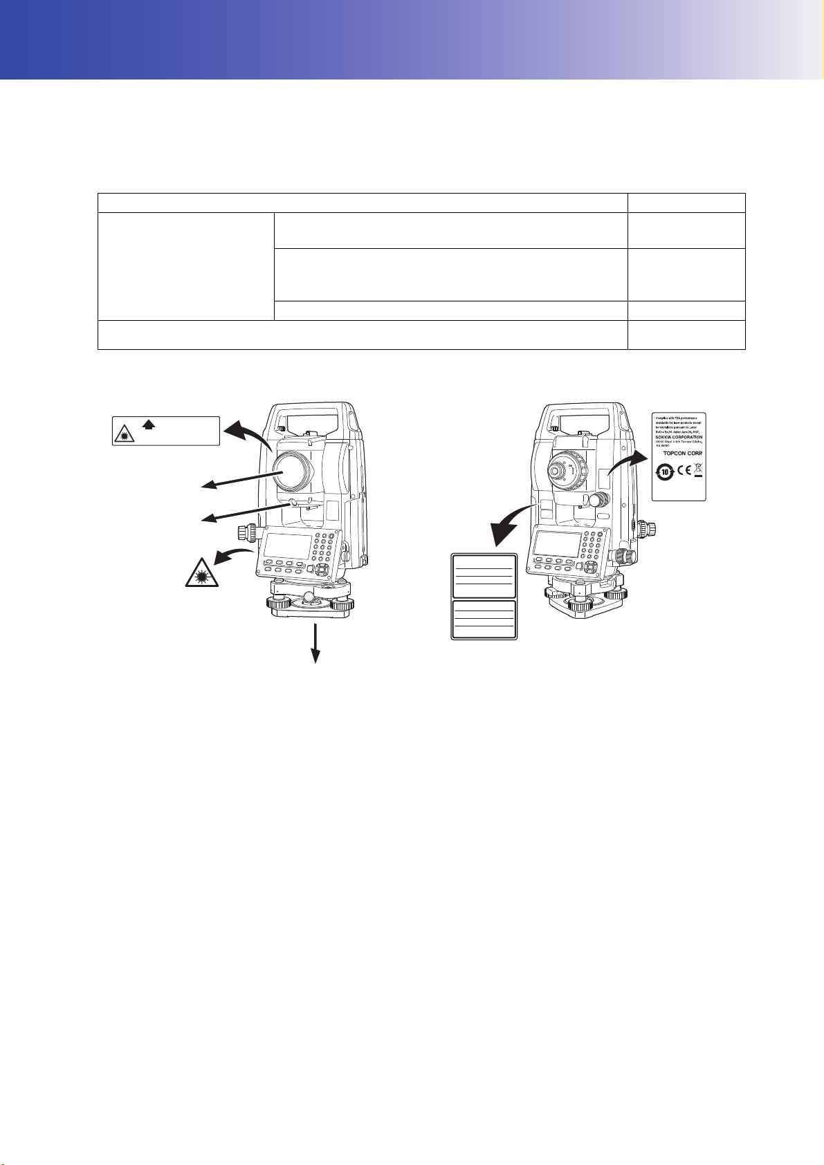
The instrument is classified as the following class of Laser Product according to IEC Standard Publication
60825-1 Ed.3.0: 2014 and United States Government Code of Federal Regulation FDA CDRH 21CFR Part
1040.10 and 1040.11 (Complies with FDA performance standards for laser products except for deviations
pursuant to Laser Notice No.50, dated June 24, 2007.)
Device Laser class
Light beam used for measurement
(When target (reflector) is set to N-prism.)
EDM device in objective
lens
Light beam used for measurement
(When target (reflector) is set to prism or reflective
sheet.)
Laser-pointer Class 3R
Laser plummet
*1
*1: Laser plummet is available as a factory option depending on the country or the area where the
instrument is purchased.
Class 3R
Class 1
Class2
• EDM device is classified as Class 3R Laser Product when reflectorless measurement is selected. When
target (reflector) is set to prism or reflective sheet, the output is equivalent to the safer class 1.
Warning
• Use of controls or adjustments or performance of procedures other than those specified herein may result in
hazardous radiation exposure.
• Follow the safety instructions on the labels attached to the instrument as well as in this manual to ensure safe
use of this laser product.
• Never intentionally point the laser beam at another person. The laser beam is injurious to the eyes and skin.
If an eye injury is caused by exposure to the laser beam, seek immediate medical attention from a licensed
ophthalmologist.
• Do not look directly into the laser beam source or guide light source. Doing so could cause permanent eye
damage.
• Do not stare at the laser beam. Doing so could cause permanent eye damage.
• Never look at the laser beam through a telescope, binoculars or other optical instruments. Doing so could
cause permanent eye damage.
• Sight targets so that the laser beam does not stray from them.
7

3. LASER SAFETY INFORMATION
Caution
• Perform checks at start of work and periodic checks and adjustments with the laser beam emitted under
normal conditions.
• When the instrument is not being used, turn OFF the power and replace the lens cap.
• When disposing of the instrument, destroy the battery connector so that the laser beam cannot be emitted.
• Operate the instrument with due caution to avoid injuries that may be caused by the laser beam
unintentionally striking a person in the eye. Avoid setting the instrument at heights at which the path of the
laser beam may strike pedestrians or drivers at head height.
• Never point the laser beam at mirrors, windows or surfaces that are highly reflective. The reflected laser beam
could cause serious injury.
• Only those who have been received training as per the following items shall use this product.
• Read this manual for usage procedures for this product.
• Hazardous protection procedures (read this chapter).
• Requisite protective gear (read this chapter).
• Accident reporting procedures (stipulate procedures beforehand for transporting the injured and
contacting physicians in case there are laser induced injuries).
• Persons working within the range of the laser beam are advised to wear eye protection which corresponds to
the laser wavelength of the instrument being used. (OD2)
• Areas in which the laser is used should be posted with a standard laser warning sign.
• When using the laser-pointer function, be sure to turn OFF the output laser after distance measurement is
completed. Even if distance measurement is canceled, the laser-pointer function is still operating and the
laser beam continues to be emitted.
8
4. PRODUCT OUTLINE
2
1
6
4
3
5
7
8
9
11
10
12
13
14
15
30
Low Temperature Models (iM-102L/105L) only*
28
29
* They may be included in the standard model de-
pending on the country or the area where the instrument is purchased.
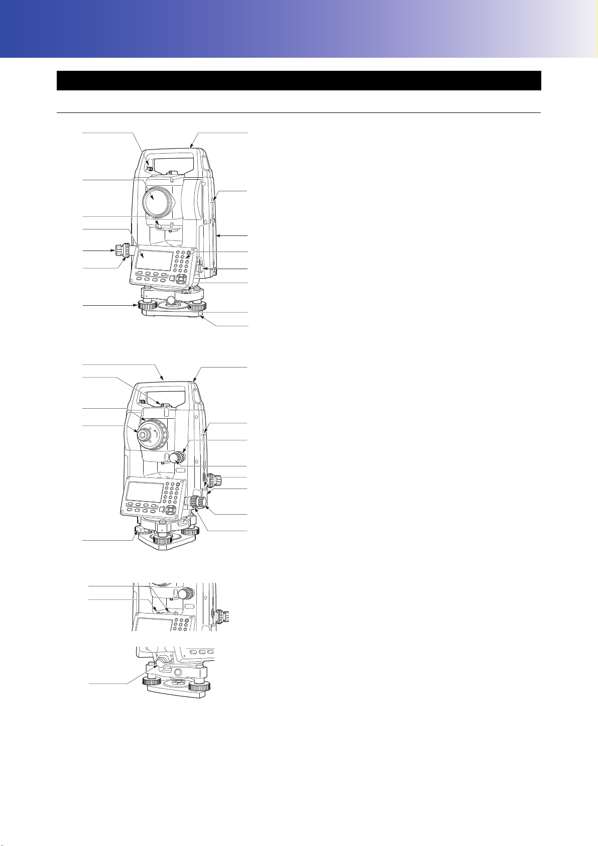
4.1 Parts of the Instrument
Parts and functions of the instrument
27
26
25
24
23
16
2
17
18
19
20
21
22
1 Handle
2 Instrument height mark
3 Battery cover
4 Operation panel
5 Serial connector
6 Circular level
7 Circular level adjusting screws
8 Base plate
9 Levelling foot screw
10 Optical plummet focussing ring
11 Optical plummet eyepiece
(10,11: Not included in instruments with laser plummet)
12 Display unit
13 Guide light
14 Objective lens (Includes Laser-pointer function)
15 Handle locking screw
16 Tubular compass slot
17 Vertical clamp
18 Vertical fine motion screw
19 Trigger key
20 External interface hatch (USB port/Reset button)
21 Horizontal fine motion screw
22 Horizontal clamp
23 Tribrach clamp
24 Telescope eyepiece screw
25 Telescope focussing ring
26 Sighting collimator
27 Instrument center mark
28 Plate level
29 Plate level adjusting screw
30 Combined communications and power source
connector
9

4. PRODUCT OUTLINE
Red
Green
Guide light
(When seen from the objective lens side
while the instrument is in the Face 1 state)
Instrument height mark
The height of the instrument is as follows:
• 192.5 mm (from tribrach mounting surface to this mark)
• 236 mm (from tribrach plate to this mark)
"Instrument height" is input when setting instrument station data and is the height from the surveying point
(where the instrument is mounted) to this mark.
Trigger Key
Press the trigger key when the iM is in the OBS mode or when [MEAS]/[STOP] is indicated on the display
unit. You can start/stop measurement.
In the screen displaying [AUTO], press trigger key to perform automatic operation from distance
measurement to recording.
Laser-pointer function
A target can be sighted with a red laser beam in dark locations without the use of the telescope.
Sighting collimator
Use sighting collimator to aim the iM in the direction of the measurement point. Turn the instrument until
the triangle in the sighting collimator is aligned with the target.
Guide light
Setting-out measurement etc. can be carried out effectively using the Guide light. The Guide light is
composed of a light that is divided into a red and a green light. A poleman can ascertain the present
position by checking the Guide light color.
Red
Green
Green Red
Guide light status
Light status Meaning
Red (From position of poleman) Move target left
Green (From position of poleman) Move target right
Red and Green Target is at correct horizontal position
When the guide light is turned ON, it is displayed as a symbol in the display unit.
"5.2 Display Functions"
10
4. PRODUCT OUTLINE
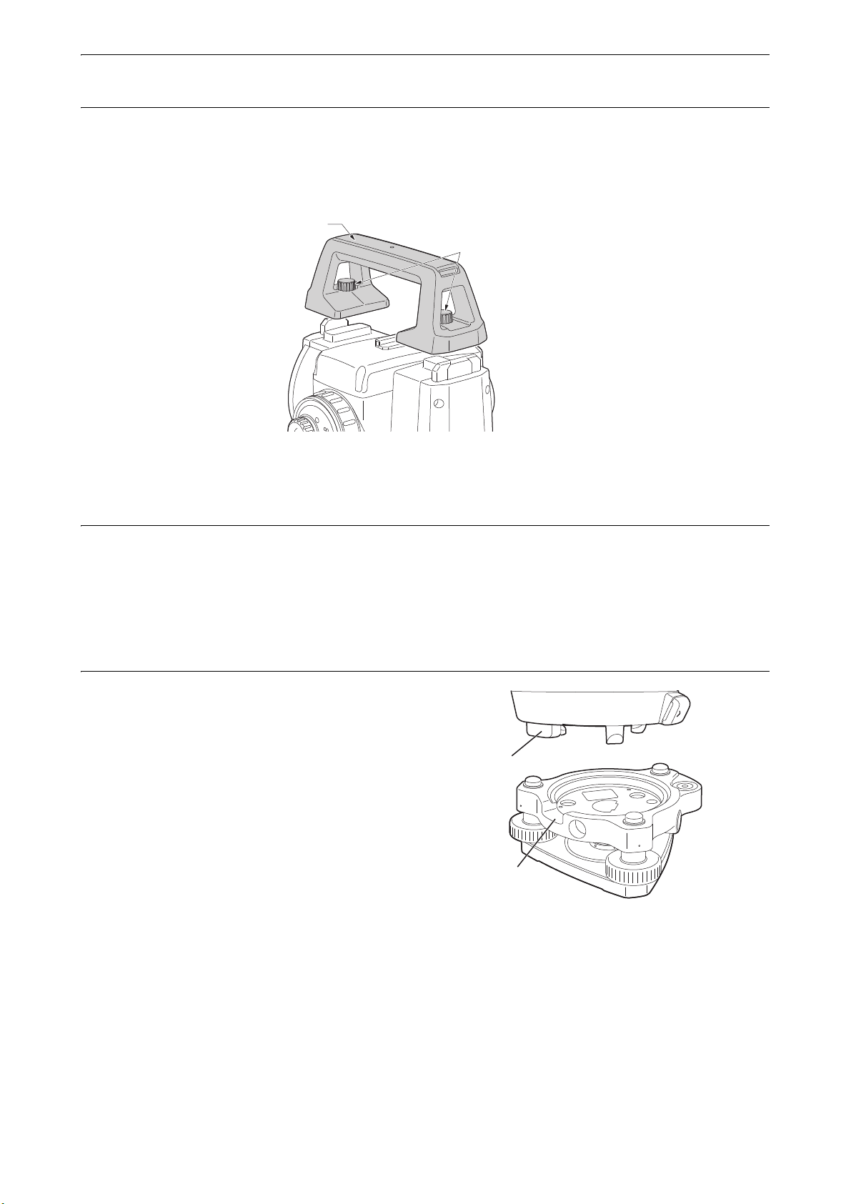
Handle rocking screws
Handle
(1)
(2)
Detaching/attaching the Handle
The carrying handle can be removed from the instrument when the prism is located at the zenith etc.
1. To remove it, loosen the handle rocking screws.
2. To attache the handle, position the handle as shown, tighten the 2 handle rocking screws securely.
Detaching the instrument from the tribrach
1. Turn the tribrach clamp counterclockwise to
loosen.
2. Lift the instrument to detach.
Attaching the instrument to the tribrach
1. Align (1) and (2) and lower the instrument onto the
tribrach.
2. Turn the tribrach clamp clockwise to tighten.
3. Turn the tribrach locking screw (3) clockwise to
tighten.
11
4. PRODUCT OUTLINE
('0
࣓ࢽ࣮ࣗ
ࢳࣝࢺ
௵ពゅ
ᑐᅇ
ᨺᑕ
ᮺᡴ
࢜ࣇࢭࢵࢺ
P. 1
P. 2
P. 1
P. 2
P. 3
Data Mode Configuration Mode
P. 1
P. 2 P. 3
USB Mode
P. 1
P. 2
{ESC}
{ESC}
[DATA][USB] [CNFG]
{ }
Status Screen
P. 1
"MENU"
"TOPO"
P. 2
P. 3
{ESC}
[OBS]
[MENU]
[TOPO]
{ESC}
㊰⥺ィ⟬
Star key Mode
OBS Mode
OFFSET
TOPO
S-OMLM
Intersect.
Traverse
Road
Xsection
Quick format
Data
JOB
Known data
Code
REM
Area calc.
S-O Line
P-Project
PT to line
S-O Arc
Dist+Coord
Note
View
Deletion
TILT
H-SET
EDMMENU
OBS
PC 0
0ppm
SD
ZA
HA-R
890590050
00
SHVMEAS 0SET
COORD
iM-103
S/N XX123456
Date Jan/01/2017
Time 12:00:00
rec 49999
CNFGOBS USB DATA
iM-103
S/N XX123456
Internal Pt. :50000
Bluetooth
rec 49999
CNFGOBS USB DATA
iM-103
S/N XX123456
Ver. X.XXXX_XX
X.XXX
Job.JOB1
rec 49999
CNFGOBS USB DATA
USB
Save data
Load known PT
Save code
Load code
File status
TOPO JOB1
Occupy
BS data
Angle data
Dist data
Coord data
MENU
Coordinate
S-O
Topography
MLM
Offset
Config
Instr.config
Key function
Comms setup
Instr.const
Obs.condition
Laser plum :Off
Laser lev. :3
Illum.hold :Laser
L-pointer :Off
Off On
Tilt crn :Ye s ( H, V )
Contrast :10
Reticle lev :3
Reflector :Prism
Yes(H, V) Yes(V) No
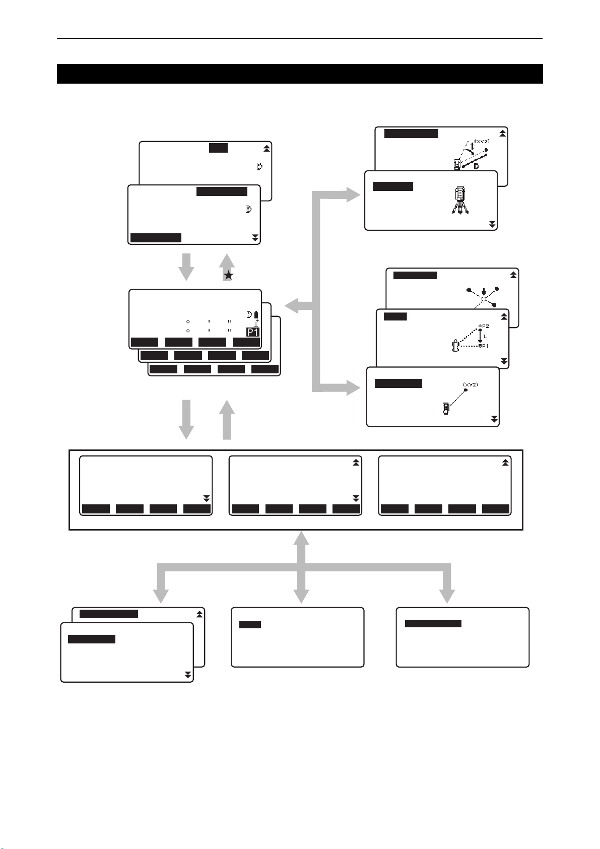
4.2 Mode Structure
The diagram below describes the different modes of the instrument and key operations for navigating between
them.
• "TSshield" and "Cloud OAF" may not be installed depending on the model or TSshield/Cloud OAF model may
not be available depending on the country or the area where the instrument is purchased.
12

4. PRODUCT OUTLINE
4.3 Bluetooth Wireless Technology/Wireless LAN
• Bluetooth/Wireless LAN function may not be built in depending on telecommunications regulations of the
country or the area where the instrument is purchased. Contact your local dealer for the details.
• Use of this technology must be authorized according to telecommunications regulations of the country where
the instrument is being used. Contact your local dealer in advance.
"42. REGULATIONS"
• TOPCON CORPORATION is not liable for the content of any transmission nor any content related thereto.
When communicating important data, run tests beforehand to ascertain that communication is operating
normally.
• Do not divulge the content of any transmission to any third party.
Radio interference when using Bluetooth technology/Wireless LAN
Bluetooth/Wireless LAN communication with the iM uses the 2.4GHz frequency band. This is the same band
used by the devices described below.
• Industrial, scientific, and medical (ISM) equipment such as microwaves and pacemakers.
• portable premises radio equipment (license required) used in factory production lines etc.
• portable specified low-power radio equipment (license-exempt)
• IEEE802.11b/IEEE802.11g/IEEE802.11n standard wireless LAN devices (When using Bluetooth function)
• The above devices use the same frequency band as Bluetooth communications. As a result, using the iM
within proximity to the above devices may result in interference causing communication failure or reduction
of transmission speed.
• Bluetooth devices (when Wireless LAN function)
Although a radio station license is not required for this instrument, bear in mind the following points when using
Bluetooth technology for communication.
Regarding portable premises radio equipment and portable specified low-power radio equipment:
• Before starting transmission, check that operation will not take place within the vicinity of portable premises
radio equipment or specified low-power radio equipment.
• In the case that the instrument causes radio interference with portable premises radio equipment,
terminate the connection immediately and take measures to prevent further interference (e.g. connect
using an interface cable).
• In the case that the instrument causes radio interference with portable specified low-power radio
equipment, contact your local dealer.
When using Bluetooth function in proximity to IEEE802.11b/IEEE802.11g/IEEE802.11n standard
wireless LAN devices, turn off all wireless LAN devices not being used and vice versa.
• Interference may result, causing transmission speed to slow or even disrupting the connection completely.
Turn off all devices not being used.
Do not use the iM in proximity to microwaves.
• Microwave ovens can cause significant interference resulting in communication failure. Perform
communication at a distance of 3 m or more from microwave ovens.
13

4. PRODUCT OUTLINE
Refrain from using the iM in proximity to televisions and radios.
• Televisions and radios use a different frequency band to Bluetooth/Wireless LAN communications.
However, even if the iM is used within proximity to the above equipment with no adverse effects with regard
to Bluetooth/Wireless LAN communication, moving a Bluetooth/Wireless LAN compatible device
(including the iM) closer to said equipment may result in electronic noise in sound or images, adversely
affecting the performance of televisions and radios.
Precautions regarding transmission
For best results
• The usable range becomes shorter when obstacles block the line of sight, or devices such as
PDAs or computers are used. Wood, glass and plastic will not impede communication but the usable range
becomes shorter. Moreover, wood, glass and plastic containing metal frames, plates, foil and other heat
shielding elements as well as coatings containing metallic powders may adversely affect Bluetooth
communication and concrete, reinforced concrete, and metal will render it impossible.
• Use a vinyl or plastic cover to protect the instrument from rain and moisture. Metallic materials should not
be used.
• The direction of the Bluetooth antenna can have adverse effects upon usable range.
Reduced range due to atmospheric conditions
• The radio waves used by the iM may be absorbed or scattered by rain, fog, and moisture from the human
body with the limit of usable range becoming lower as a result. Similarly, usable range may also shorten
when performing communication in wooded areas. Moreover, as wireless devices lose signal strength
when close to the ground, perform communication at as high a position as possible.
• TOPCON CORPORATION cannot guarantee full compatibility with all Bluetooth/Wireless LAN products on
the market.
14
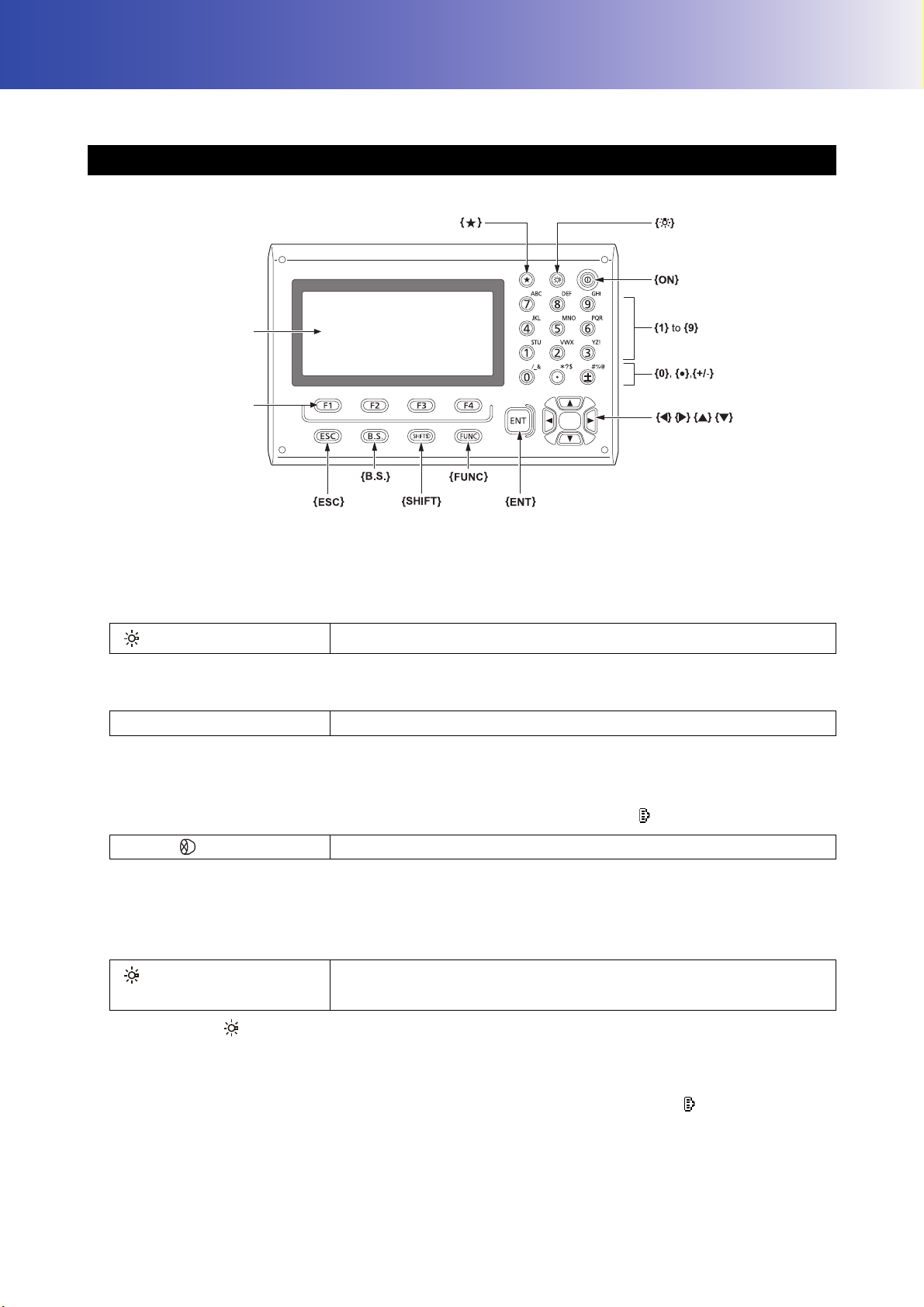
5. BASIC OPERATION
Softkey selection
Display unit
Starkey
Power key
Illumination key
Learn basic key operations here before you read each measurement procedure.
5.1 Basic Key Operation
Power ON/OFF
"8. POWER ON/OFF"
Lighting up the reticle/keys
{}
Switching to Starkey mode
{
}
Switches the reticle illumination and key light On/Off
Switches to Starkey mode/previous screen
"5.3 Starkey Mode"
Switching target type
Target type can be switched only on the screen where the target symbol (ex. ) is displayed.
{SHIFT}
Target symbol displayed: "5.2 Display Functions", Switching between target types in the Starkey mode:
"5.3 Starkey Mode", Switching the target type in Config mode": "33.2 Observation Conditions - Dist"
Switching the Laser-pointer/Guide light ON/OFF
{} (Press and hold until a
beep sounds
)
Switches between target types (Prism/Sheet/N-Prism (reflectorless))
Turns ON/OFF the laser-pointer/guide light
"Switching {} function: "33.7 Instrument Conditions - Instrument""
• After turning ON the laser-pointer/guide light, the laser beam is emitted for 5 minutes, and then
automatically switches OFF. But in the Status screen and when target symbol (ex. ) is not displayed in
the OBS mode, the laser beam is not automatically turned off.
15

Softkey operation
JOB details
JOB name
JOB M
SCALE: 1.00000000
A
OK
Softkeys are displayed on the bottom line of the screen.
5. BASIC OPERATION
{F1} to {F4}
{FUNC}
Inputting letters/figures
{SHIFT}
Select the function matching the softkeys
Toggle between OBS mode screen pages (when more than 4 softkeys
are allocated)
Switch between numeric and alphabetic characters.
During numeric input, input number of the key.
{0} to {9}
During alphabetic input, input the characters displayed above the key in
the order they are listed.
Input a decimal point/plus or minus sign during numeric input.
{.}/{
±}
During alphabetic input, input the characters displayed above the key in
the order they are listed.
{}/{}
{B.S.}
{ESC}
{ENT}
Move the cursor left/right
Deletes a character on the left.
Cancels the input data
Selects/accepts input word/value
Example: Entering "JOB M" in the JOB name field
1. Press {SHIFT} to enter the alphabet input mode
Alphabet input mode is indicated by an "A" on the right of the screen.
2. Press {4}.
"J" is displayed.
3. Press {5} three times.
"O" is displayed.
4. Press {7} twice.
"B" is displayed.
5. Press {} twice.
Input a blank space.
6. Press {5} once.
"M" is displayed. Press {ENT} to complete inputting.
16
Selecting options
Illum.hold: Laser
5. BASIC OPERATION
}/{}
{
{}/{}
{ENT}
Move the cursor up/down
Move the cursor/selection item left/right or select other option
Accepts the option
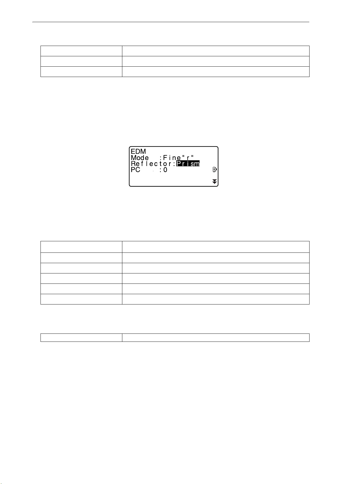
Example: Select a reflector type
1. Press [EDM] in page 2 of OBS mode.
2. Move to “Reflector” using {
}/{}.
3. Display the option you want to select using {}/{}.
Switches between “Prism”, “Sheet” and “N-prism.”
4. Press {ENT} or {
} to move to the next option.
The selection is set and you can set the next item.
Switching modes
[
]
[CNFG]
[OBS]
[USB]
[DATA]
{ESC}
From OBS mode (Observation Mode) to Starkey Mode
From Status mode to Config Mode (Configuration Mode)
From Status mode to OBS mode (Observation Mode)
From Status mode to USB Mode
From Status mode to Data Mode
Return to the Status mode from each Mode
"4.2 Mode Structure"
Others
{ESC} Returns to previous screen
17
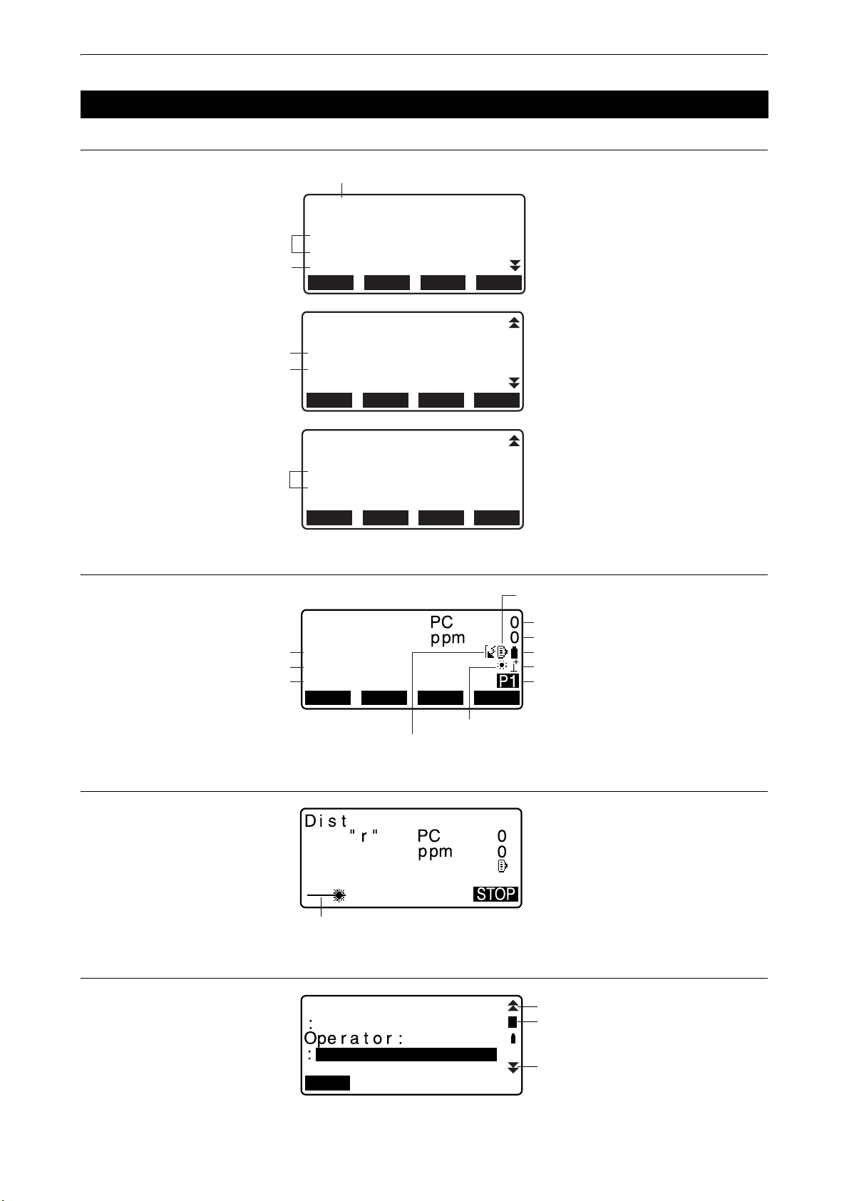
5.2 Display Functions
iM-103
S/N XX123456
Ver. X.XXXXXX
X.XXX
Job.JOB1
rec 49999
CNFGOBS USB DATA
Application
software
version
Instrument name
JOB
iM-103
S/N XX123456
Date Jan/01/2017
Time 12:00:00
rec 49999
CNFGOBS USB DATA
Date
Time
iM-103
S/N XX123456
Internal Pt. :50000
Bluetooth
rec 49999
CNFGOBS USB DATA
Functions on
your instrument
SHVMEAS 0SET
COORD
OBS
SD
ZA
HA-R
Distance *1
Vertical angle *2
Horizontal angle *3
Bluetooth communication status *8
Laser-pointer function / Guide light ON *7
Prism constant value
Atmospheric correction factor
Remaining battery power *4
Tilt angle compensation *6
Page number
Target *5
F
i
n
e
Laser is emited *9
A
Previous page
Next page
Input mode *10
OK
CD
Status screen
5. BASIC OPERATION
OBS mode screen
Measuring screen
Top menu
18
5. BASIC OPERATION
• "TSshield" and "Cloud OAF" may not be installed depending on the model or TSshield/Cloud OAF model may
not be available depending on the country or the area where the instrument is purchased.
(1) Distance
SD: Slope distance
HD: Horizontal distance
VD: Height difference
Switching distance display status: "33.1 Observation Conditions - Angle/Tilt"
(2) Vertical angle
ZA: Zenith angle (Z=0)
VA: Vertical angle (H=0/H=±90)
To switch vertical angle/slope in %, press [ZA/%]
Switching vertical angle display status: "33.1 Observation Conditions - Angle/Tilt"
(3) Horizontal angle
Press [R/L] to switch the display status.
HA-R: Horizontal angle right
HA-L: Horizontal angle left
(1) (2) (3)
To switch usual “SD, ZA, HA-R” display to “SD, HD, VD”, press [SHV].
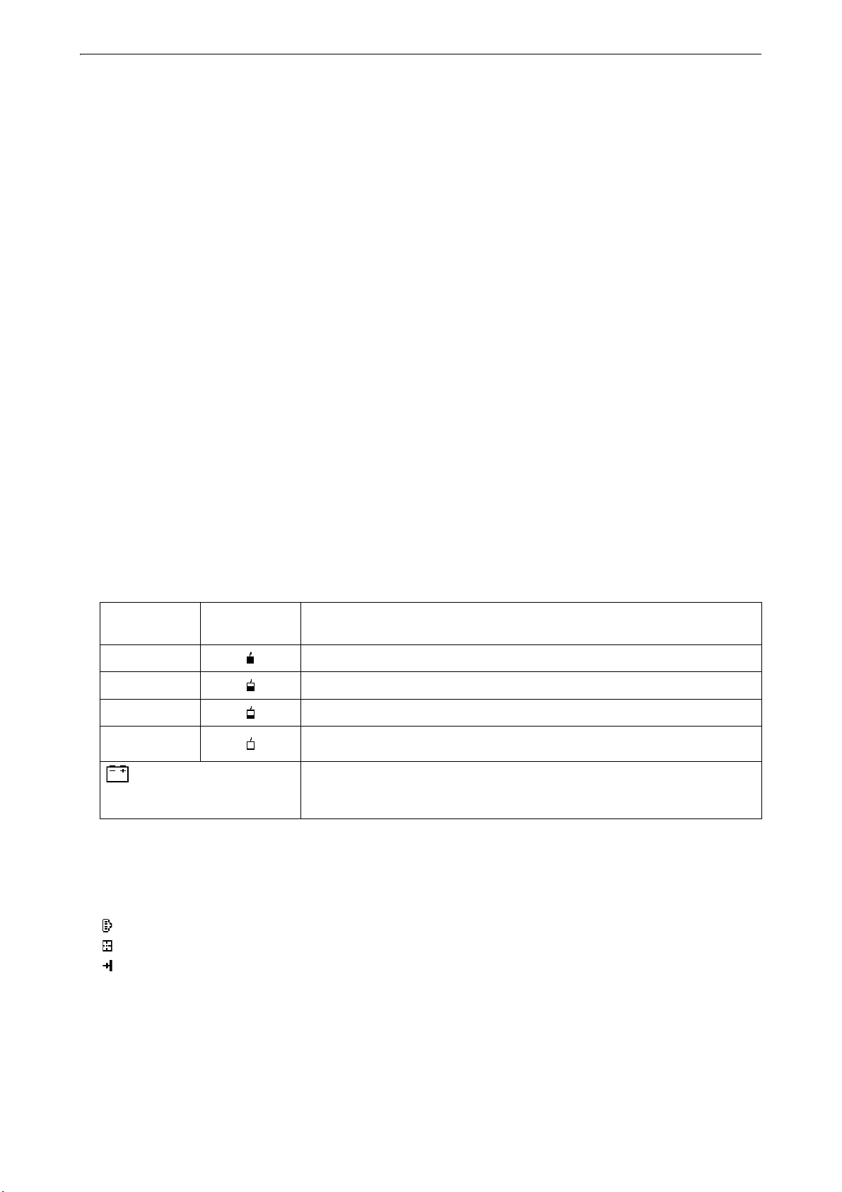
(4) Remaining battery power (Temperature=25°C, EDM on)
Using BDC70
(This symbol is displayed every
3 seconds)
"6.1 Battery Charging"
(5) Target display
Press {SHIFT} to switch the selected target. This key function can be used only on the screens on which
the target symbol is displayed.
:prism
:reflective sheet
:reflectorless
Using external
battery
level 3 Full power
level 2 Plenty of power remains.
level 1 Half or less power remains.
level 0 Little power remains.
Charge the battery.
No power remains.
Stop the measurement and charge the battery.
Battery level
(6) Tilt angle compensation
When this symbol is displayed, the vertical and horizontal angles are automatically compensated for small
tilt errors using 2-axis tilt sensor.
Tilt compensation setting: "33.1 Observation Conditions - Angle/Tilt"
19
5. BASIC OPERATION
Aa1
Tilt crn :Yes(H, V)
Contrast :10
Reticle lev :3
Reflector :Prism
Yes(H, V) Yes(V) No
Laser plum :Off
Laser lev. :3
Illum.hold :Laser
L-pointer :Off
Off On
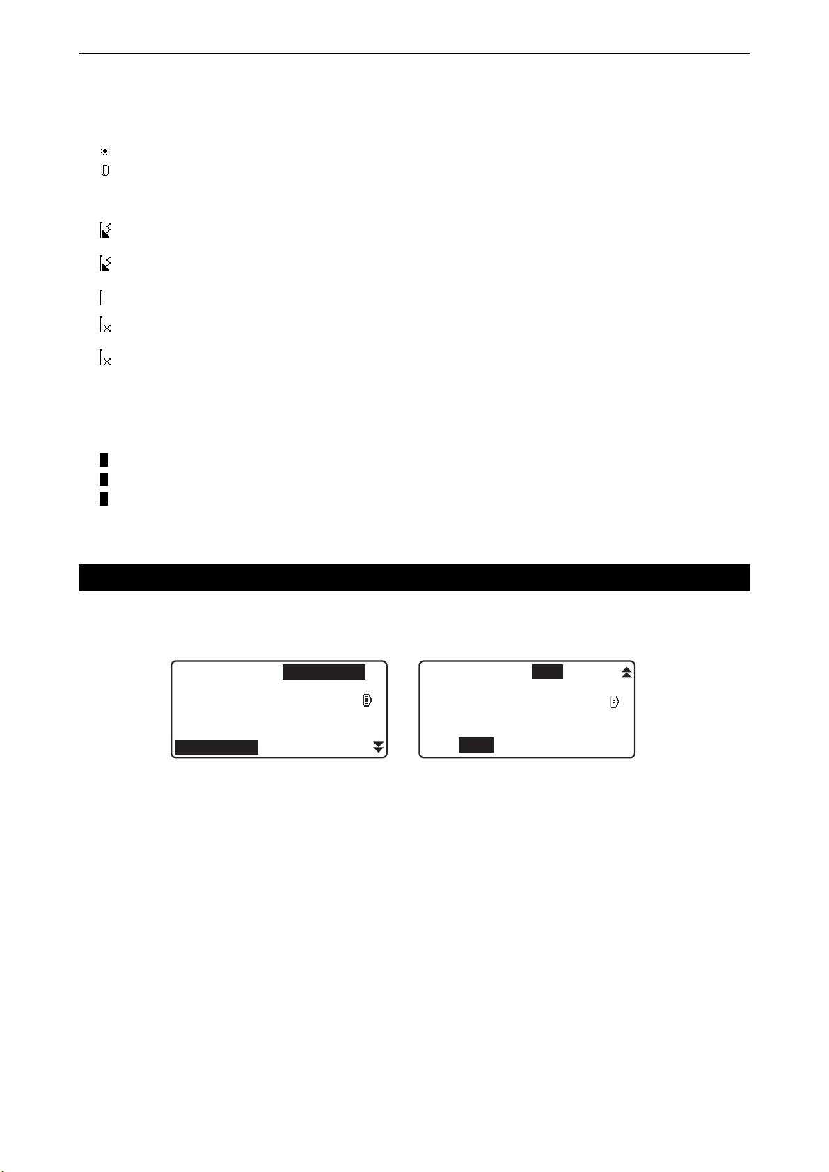
(7) Laser-pointer/Guide light display
Selecting Laser-pointer/Guide light: "33.7 Instrument Conditions - Instrument", Switching Laser-pointer/
Guide light ON/OFF: "5.1 Basic Key Operation"
:Laser-pointer is selected and ON
:Guide light is selected and ON
(8) Bluetooth communication status
:Connection established
(flashing):Connecting
(flashing): Waiting
(flashing):Disconnecting
: Bluetooth device is OFF
(9) Appears when laser beam is emitted for distance measurement
(10) Input mode
: Inputting capital letters and figures.
: Inputting small letters and figures.
: Inputting numbers.
5.3 Starkey Mode
Pressing the Starkey {
In the Starkey mode, you can change the setting commonly used for measuring.
The following operations and settings can be made in the Starkey mode
1. Turning ON/OFF tilt angle correction
2. Adjusting the display unit's contrast (Steps 0~15)
3. Adjusting reticle illmination level (Steps 0~5)
4. Switching the target type
5. Turning ON/OFF laser plummet (for the instrument with the laser centering function)
6. Setting for press and hold the illmination key
7. Turning ON/OFF laser pointer
8. Turning ON/OFF guide light
* The Starkey mode can be called only from the OBS mode.
} displays the Starkey menu.
20
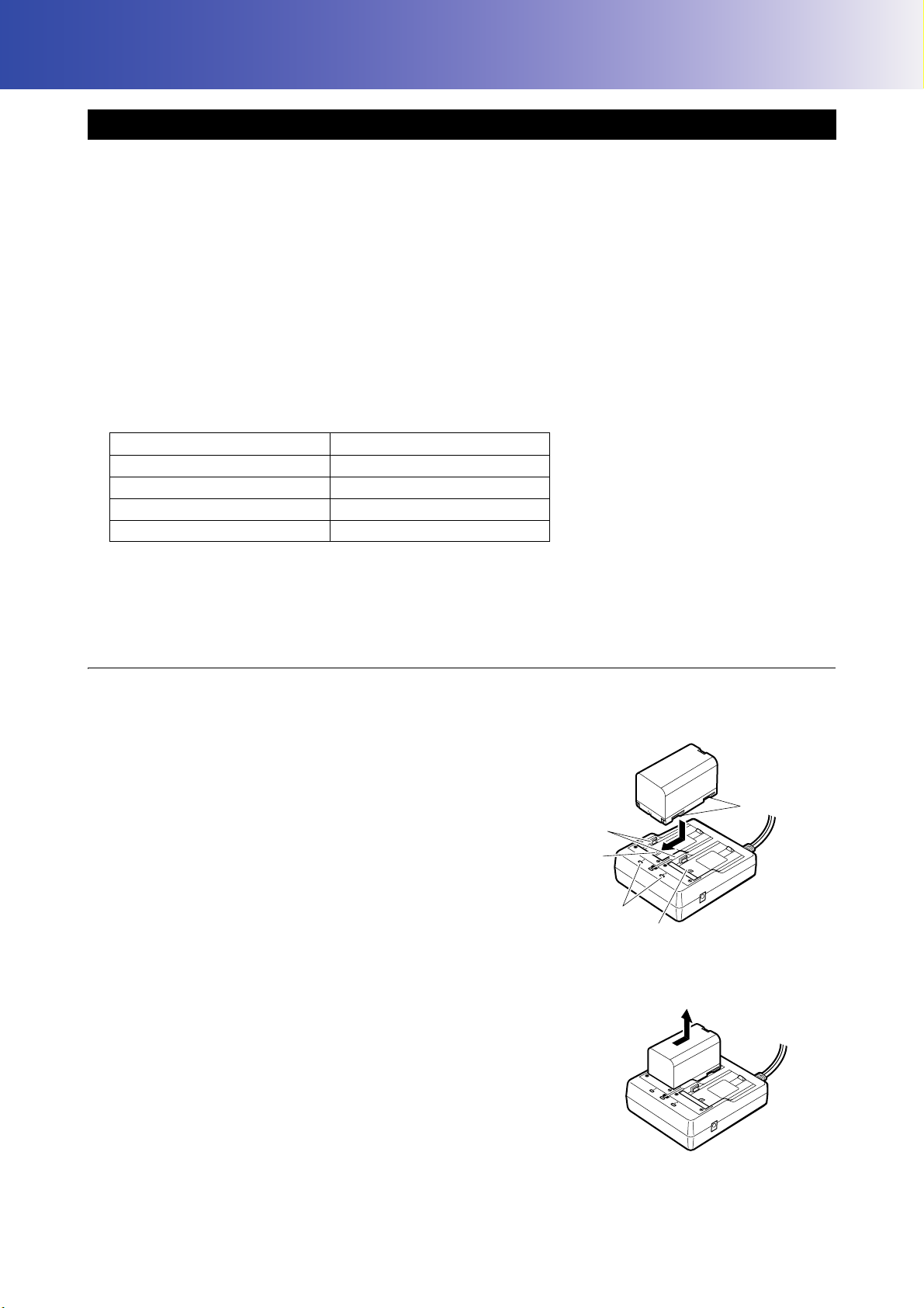
6. USING THE BATTERY
Guides
Slot 1
Slot 2
Charging lamp
Grooves
6.1 Battery Charging
Be sure to charge the battery fully before using it for the first time or after not using it for long periods.
• The charger will become rather hot during use. This is normal.
• Do not use batteries other than those designated.
• The charger is for indoor use only. Do not use outdoors.
• Batteries cannot be charged, even when the charging lamp is flashing, when the temperature is outside the
charging temperature range.
• Do not charge the battery just after charging is completed. Battery performance may decline.
• Remove batteries from the charger before putting into storage.
• When not in use, disconnect the power cable plug from the wall outlet.
• Store the battery in a dry room where the temperature is within the following ranges. For long-term storage,
the battery should be charged at least once every six months.
Storage period Temperature range
1 week or less -20 to 50°C
1 week to 1 month -20 to 45°C
1 month to 6 months -20 to 40°C
6 months to 1 year -20 to 35°C
• Batteries generate power using a chemical reaction and as a result have a limited lifetime. Even when in
storage and not used for long periods, battery capacity deteriorates with the passage of time. This may result
in the operating time of the battery shortening despite having been charged correctly. In this event, a new
battery is required.
PROCEDURE
1. Connect the power cable to the charger and plug the
charger into the wall outlet.
2. Mount the battery in the charger by matching the grooves
on the battery with the guides on the charger.
3. When charging starts, the lamp starts blinking.
4. The lamp lights when charging is finished.
5. Remove the battery and unplug the charger.
21
6. USING THE BATTERY
Battery cover
Battery
• Slots 1 and 2:
The charger starts charging the battery mounted first. If you place two batteries in the charger, the battery in
slot 1 is charged first, and then the battery in slot 2. (
• Charging lamp:
The charging lamp is off when the charger is outside the charging temperature range or when the battery is
mounted incorrectly. If the lamp is still off after the charger falls within its charging temperature range and the
battery is mounted again, contact your local dealer. (
• Charging time per battery:
BDC70: about 5.5 hours (at 25°C) (Charging can take longer than the times stated above when temperatures
are either especially high or low).
step 2)
steps 2 and 3)
6.2 Installing/Removing the Battery
Mount the charged battery.
Type of power source: "37. POWER SUPPLY SYSTEM"
• Use the attached battery (BDC70).
• Before removing the battery, turn OFF the power to the instrument.
• Do not open the battery cover while the power is on.
• When installing/removing the battery, make sure that moisture or dust particles do not come in contact with
the inside of the instrument.
• Waterproofing property for this instrument is not secured unless the battery cover and external interface hatch
are closed, and the connector caps are correctly attached. Do not use it with these open or loose, under the
condition where water or other liquid spills over the instrument. The specification grade for water proofing and
dust resistance is not guaranteed when using USB connector.
• Remove batteries from the surveying instrument or charger before putting into storage.
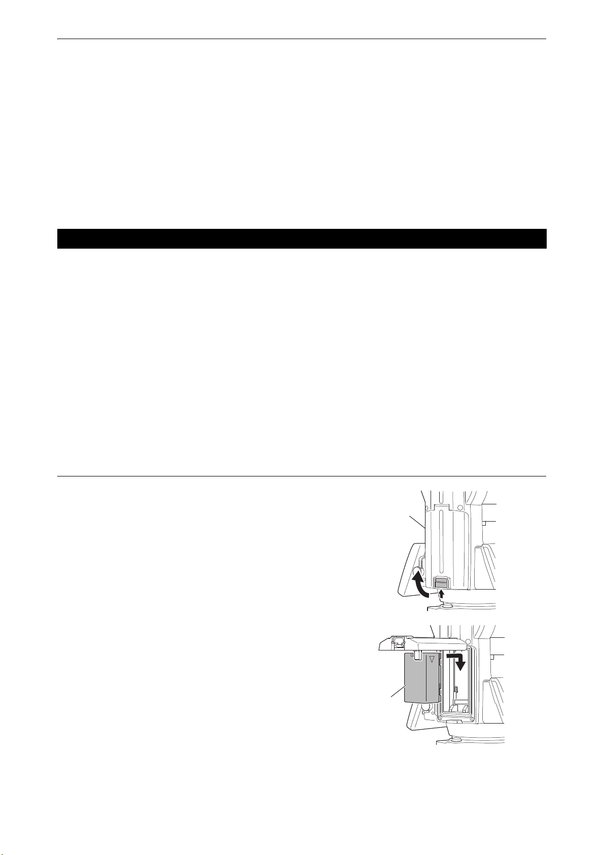
PROCEDURE Mounting the battery
1. Slide the catch on the battery cover to open.
2. Checking the terminal side on the battery, insert the
3. Close the battery cover. A click is heard when the cover is
battery as shown.
• Do not insert the battery inclined. Doing so may damage
the instrument or battery terminals.
secure.
22
7. SETTING UP THE INSTRUMENT
Centering screw
Focussing on the survey point
Focussing on
the reticle
Levelling foot screws
• Mount the battery in the instrument before performing this operation because the instrument will tilt slightly if
the battery is mounted after levelling.
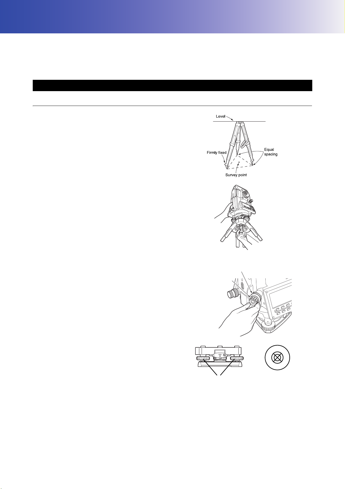
7.1 Centering
PROCEDURE Centering with the optical plummet eyepiece
1. Make sure the legs are spaced at equal intervals
and the head is approximately level.
Set the tripod so that the head is positioned over the
survey point.
Make sure the tripod shoes are firmly fixed in the
ground.
2. Place the instrument on the tripod head.
Supporting it with one hand, tighten the centering
screw on the bottom of the unit to make sure it is
secured to the tripod.
3. Looking through the optical plummet eyepiece, turn
the optical plummet eyepiece to focus on the
reticle.
Turn the optical plummet focussing ring to focus on
the survey point.
4. Adjust the levelling foot screws to center the
survey point in the optical plummet reticle.
5. Continue to the levelling procedure.
"7.2 Levelling"
23
7. SETTING UP THE INSTRUMENT
O K
L-ON
L-OFF
L-lev.
O K
PROCEDURE Centering with the laser plummet eyepiece
*1: Laser plummet is available as a factory option depending on the country or the area where the instrument
is purchased.
1. Set up the tripod and affix the instrument on the tripod head.
*1
"7.1 Centering"
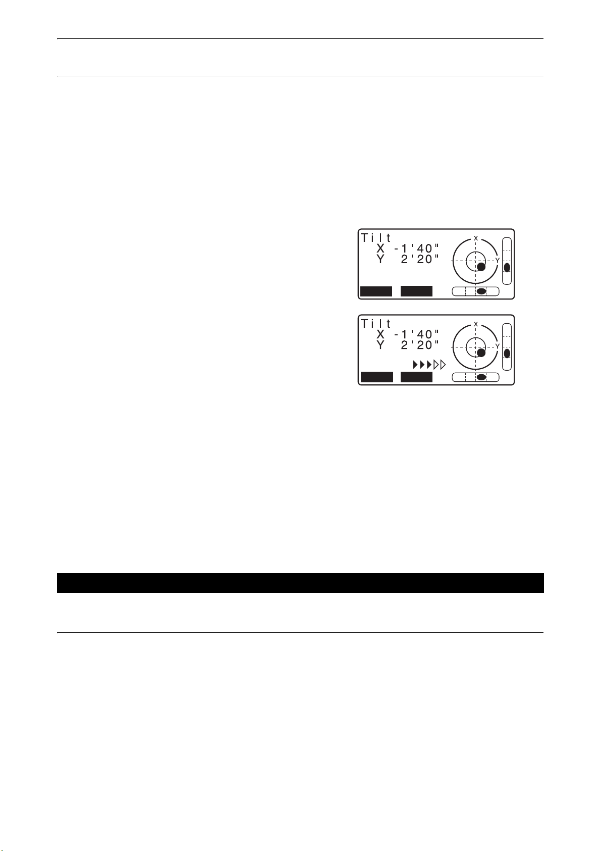
2. Power ON the instrument.
"8. POWER ON/OFF"
The electric circular level is displayed on the <Tilt>.
3. Press [L-ON].
The laser plummet beam will be emitted from the bottom of
the instrument.
• Use {}/{} in the second page to adjust the brightness of
the laser.
4. Using levelling foot screws, adjust the position of the
instrument on the tripod until the laser beam is aligned with
the center of the survey point.
5. Press [L-OFF] to turn the laser plummet off.
Alternatively, press {ESC} to return to the previous screen.
The laser plummet will switch off automatically.
• Visibility of the laser spot may be affected when operating in direct sunlight. In this event, provide shade for
the survey point.
7.2 Levelling
PROCEDURE
1. Perform the centering procedure.
"7.1 Centering"
24
 Loading...