

Page 1
Operator’s
Manual
Diesel Powered
P/N 11809A
September 2005 V2
Page 2

LIMITED WARRANTY
Snorkel warrants each new machine manufactured and sold by it to be free from defects in material and workmanship for a
period of one (1) year from date of delivery to a Customer or for one year after the machine has been placed in first service in a
Dealer rental fleet, whichever comes first. Any part or parts which, upon examination by the Snorkel Service Department, are
found to be defective, will be replaced or repaired, at the sole discretion of Snorkel, through its local Authorized Dealer at no
charge.
Snorkel further warrants the structural components; specifically, the mainframe chassis, turntable, booms and scissor arms,
of each new machine manufactured by it to be free from defects in material and workmanship for an additional period of four
(4) years. Any such part or parts which, upon examination by the Snorkel Service Department, are found to be defective will
be replaced or repaired by Snorkel through its local Authorized Dealer at no charge; however, any labor charges incurred as a
result of such replacement or repair will be the responsibility of the Customer or Dealer.
The Snorkel Service Department must be notified within forty-eight (48) hours of any possible warranty situation during the
applicable warranty period. Personnel performing warranty repair or replacement must obtain specific approval by Snorkel
Service Department prior to performing any warranty repair or replacement.
Customer and Dealer shall not be entitled to the benefits of this warranty and Snorkel shall have no obligations hereunder
unless the “Pre-Delivery and Inspection Report” has been properly completed and returned to the Snorkel Service
Department within ten (10) days after delivery of the Snorkel product to Customer or Dealer’s rental fleet. Snorkel must be
notified, in writing, within ten (10) days, of any machine sold to a Customer from a Dealer’s rental fleet during the warranty
period.
At the direction of the Snorkel Service Department, any component part(s) of Snorkel products to be replaced or repaired
under this warranty program must be returned freight prepaid to the Snorkel Service Department for inspection. All warranty
replacement parts will be shipped freight prepaid (standard ground) from the Snorkel Service Department or from Snorkel’s
Vendor to Dealer or Customer.
REPLACEMENT PARTS WARRANTY
Any replacement or service part made or sold by Snorkel is not subject to the preceding Limited Warranty beyond the
normal warranty period of the machine upon which the part was installed.
THIS WARRANTY EXCLUDES AND SNORKEL DOES NOT WARRANT:
1. Engines, motors, tires and batteries which are manufactured by suppliers to Snorkel, who furnish their own warranty.
Snorkel will, however, to the extent permitted, pass through any such warranty protection to the Customer or Dealer.
2. Any Snorkel product which has been modified or altered outside Snorkel’s factory without Snorkel’s written approval, if
such modification or alteration, in the sole judgment of Snorkel’s Engineering and/or Service Departments, adversely
affects the stability, reliability or service life of the Snorkel product or any component thereof.
3. Any Snorkel product which has been subject to misuse, improper maintenance or accident. “Misuse” includes but is
not limited to operation beyond the factory-rated load capacity and speeds. “Improper maintenance” includes but is not
limited to failure to follow the recommendations contained in the Snorkel Operation, Maintenance, Repair Parts
Manuals. Snorkel is not responsible for normal maintenance, service adjustments and replacements, including but not
limited to hydraulic fluid, filters and lubrication.
4. Normal wear of any Snorkel component part(s). Normal wear of component parts may vary with the type application or
type of environment in which the machine may be used; such as, but not limited to sandblasting applications.
5. Any Snorkel product that has come in direct contact with any chemical or abrasive material.
6. Incidental or consequential expenses, losses, or damages related to any part or equipment failure, including but not
limited to freight cost to transport the machine to a repair facility, downtime of the machine, lost time for workers, lost
orders, lost rental revenue, lost profits or increased cost.
This warranty is expressly in lieu of all other warranties, representations or liabilities of Snorkel, either expressed or implied,
unless otherwise amended in writing by Snorkel’s President, Vice President-Engineering, Vice President-Sales or Vice
President-Marketing.
SNORKEL MAKES NO WARRANTIES WHICH EXTEND BEYOND THE DESCRIPTION OF THIS LIMITED WARRANTY.
SNORKEL MAKES NO IMPLIED WARRANTY OF MERCHANTABILITY OR FITNESS FOR A PARTICULAR PURPOSE
AND DISCLAIMS ALL LIABILITY FOR INCIDENTAL OR CONSEQUENTIAL DAMAGES, INCLUDING BUT NOT
LIMITED TO INJURY TO PERSONS OR PROPERTY.
The Customer shall make all warranty claims through its local Authorized Dealer and should contact the Dealer from whom
the Snorkel product was purchased for warranty service. Or, if unable to contact the Dealer, contact the Snorkel Service
Department for further assistance.
Ef fec tive July 1995
© Snorkel – all rights reserved Printed in New Zealand
Page 3
■
DANGER
DANGER
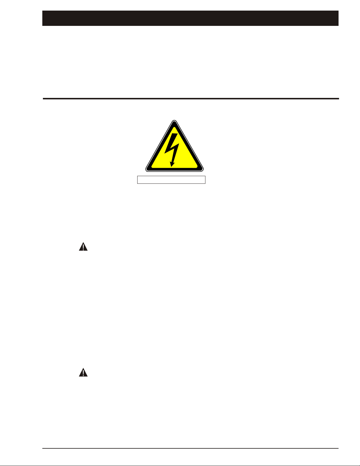
Electrical Hazard Warning
Electrical Hazard
Electrical Hazard
SP ELEVATING WORK PLATFORMS
ARE NOT ELECTRICALLY INSULATED.
If the plat form, booms, or any other con duc tive part of an SP con tacts a high-voltage elec tri cal con duc tor,
the re sult can be SERIOUS INJURY or DEATH for per sons on or near the ma chine.
GO NO CLOSER THAN THE MINIMUM SAFE APPROACH DISTANCES
(M.S.A.D) - AS OUTLINED IN TABLE 1. AND FIGURE 1.,
ON THE NEXT PAGE.
Be sure to al low for sag and sway in the wires and the work plat form.
If an SP comes in contact with a live electrical conductor, the entire machine can be charged.
If that happens, you should remain on the machine and not contact any other structure or object within
reach. That includes the ground, adjacent buildings, poles, and any object not a part of the SP.
Such con tact could make your body a con duc tor to the other ob ject cre at ing an elec tri cal shock haz ard
re sult ing in SERIOUS INJURY or DEATH.
DO NOT attempt to enter or leave the SP until you are sure the electricity has been turned off.
If an SP is in contact with a live conductor, the platform operator MUST warn others on the ground in the
vicinity of the SP to STAY AWAY from the machine, since their bodies can also form a path for electricity to
ground thus creating an electrical shock hazard with possible ELECTROCUTION and DEATH.
DO NOT attempt to operate SP ground controls when the platform, scissors arm assembly, or any other
conducting part of the SP is in contact with electrical wires or if there is an immediate danger of such
contact.
Re gard all con duc tors as en er gized.
Personnel working on or near an SP must be continuously aware of electrical hazards, recognizing that
SERIOUS INJURY or DEATH can result if contact with an electrical wire does occur.
Operators must check local power regulations before using the SP unit near power
lines
SP20/SP22 – 11890A page - i
Page 4
Electrical Hazard
Denotes
prohibited
zone
■
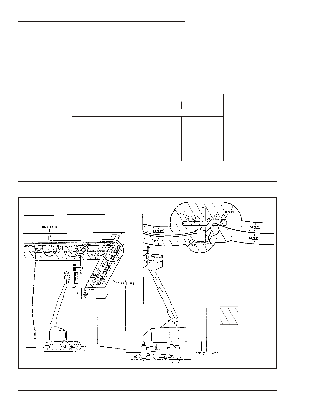
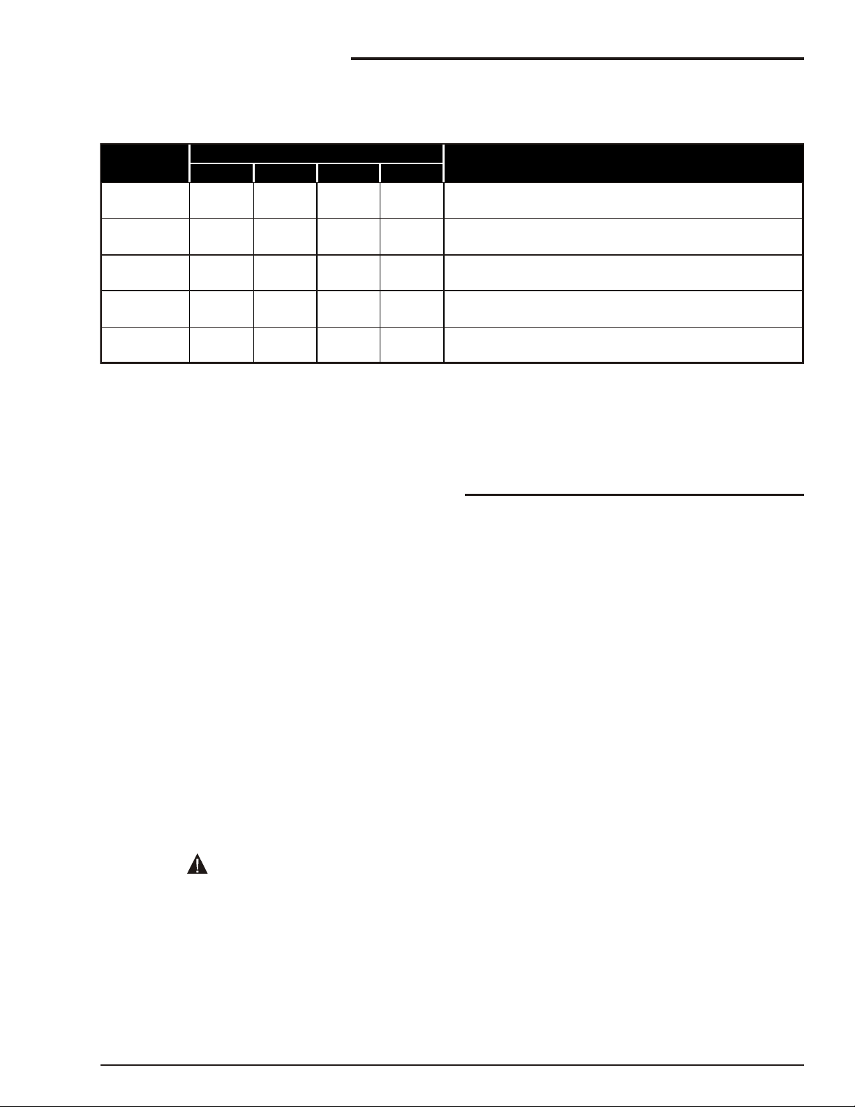
Minimum Safe Approach Distance
An SP is an all metal NOT ELECTRICALLY INSULATED, aerial work platform. DO NOT operate it near
ELECTRICAL conductors. Regard all conductors as being energized. Use the table and illustration below
to determine safe clearance from electrical conductors. (Table 1 and Figure 1, below, are from ANSI/SIA
A92.6–1990 Standard, reprinted with permission of Scaffold Industry Association.)
❑ Table 1 - (M.S.A.D.)
Minimum Safe Approach Distance
to energized (exposed or insulated power lines)
Voltage range Minimum safe approach distance
(phase to phase)
0 to 300V
over 300v to 50kv
over 50kv to 200kv
over 200kv to 350kv
over 350kv to 500kv
over 500kv to 750kv
over 750kv to 1000kv
(Feet) (Meters)
Avoid contact
10
15
20
25
35
45
3.05
4.60
6.10
7.62
10.67
13.72
❑ Figure 1 - (M.S.A.D.)
page - ii SP20/SP22 – 11890A
Page 5
Introduction
DANGER
CAUTION
DANGER
The aerial platform is a boom-supported elevating
work platform used to raise personnel, their tools,
and material to the workstation. The booms are
raised and lowered with hydraulic cylinders.
Hydraulic motors on each of the drive wheels
provide power to move the aerial platform.
The aerial platform has been manufactured to
conform to all applicable requirements of the
following organizations.
●
Occupational Safety and Health
Administration (OSHA)
●
American National Standards Institute (ANSI)
●
Canadian Standards Association (CSA)
●
Australian Standard Association (AS)
●
European Standard (EN)
This manual provides information for safe and
proper operation of the aerial platform. Read and
understand the information in this manual before
operating the aerial platform on the job.
Additional copies of this manual may be ordered
from Snorkel. Supply the model and manual part
number from the front cover to assure that the
correct manual will be supplied.
All information in this manual is based on the latest
product information at the time of publication.
Snorkel reserves the right to make product
changes at any time without obligation.
■
Safety Alerts
A safety alert symbol is used throughout this
manual to indicate danger and caution instructions.
Follow these instructions to reduce the likelihood of
personal injury and property damage. The terms
danger and caution indicate varying degrees of
personal injury or property damage that can result
if the instruction is not followed.
Indicates a situation which if not avoided
can result in death or serious injury.
Indicates a situation which if not avoided
can result in minor injury or property
damage.
Notes
Notes are used to provide special information or
helpful hints to assist in aerial platform operation, but
do not indicate a hazardous situation.
■
Options
This manual provides information about the
following options even though some machines
may not be equipped with them.
●
Diesel liquid cooled engine
●
Diesel air cooled engine
●
Spark arrestor muffler
●
Sound suppression kit
●
Driving lights
●
Platform work lights
●
Platform control box cover
●
Swinging platform gate
●
8¢ aluminum platform
●
Air line to platform
●
Hostile environment kit
●
Cold weather start-up kit
●
Hydraulic system warm-up kit
●
Vandalism protection kit
●
Tow kit
●
AC generator
●
CE certification
■
Operation
The aerial platform has built-in safety features and
has been factory tested for compliance with
Snorkel specifications and industry standards.
However, any personnel lifting aerial platform can
be potentially dangerous in the hands of untrained
or careless operators.
The potential for an accident increases when
the aerial platform is operated by personnel
who are not trained and authorized. Death or
serious injury can result from such
accidents. Read and understand the
information in this manual and on the
placards and decals on the machine before
operating the aerial platform on the job.
Training is essential and must be performed by a
qualified person. Become proficient in knowledge
and actual operation before using the aerial
platform on the job. You must be authorized to
operate the aerial platform.
The operator bears ultimate responsibility for
following all manufacturer’s instructions and
warnings, regulations and safety rules of their
employer and/or any state or federal law.
SP20/SP22 – 11890A page - iii
Page 6

Introduction
■
Maintenance
Every person who maintains, inspects, tests, or
repairs the aerial platform must be qualified to do
so. Following the daily prestart inspection in this
Operator’s Manual will help keep the aerial
platform in optimum working condition. Other
maintenance functions must be performed by
maintenance personnel who are qualified to work
on the aerial platform.
Do not modify this aerial platform without prior
written consent of the Snorkel Engineering
Department. Modification may void the warranty,
adversely affect stability, or affect the operational
characteristics of the aerial platform.
■
Manual of Responsibilities
All owners and users of the aerial platform must
read, understand, and comply with all applicable
regulations. Ultimate compliance to OSHA
regulations is the responsibility of the user and their
employer.
ANSI publications clearly identify the
responsibilities of all personnel who may be
involved with the aerial platform. A reprint of the
“Manual of Responsibilities for Dealers, Owners,
Users, Operators, Lessors and Lessees of
ANSI/SIA A92.5-1992 Boom-Supported Elevating
Work Platforms” is available from Snorkel dealers
or from the factory upon request.
Copies are also available from:
Scaffold Industry Association, Inc.
14039 Sherman Way
Van Nuys, CA 91405-2599
■
Additional Information
For additional information contact your local dealer
or Snorkel at:
Snorkel
P.O. Box 1041
Levin 5500
New Zealand
+64 6 3689168
page - iv SP20/SP22 – 11890A
Page 7

Table of Contents
Electrical Hazard
Electrical Hazard Warning .................-i
Minimum Safe Approach Distance ..........-ii
Table 1 - (M.S.A.D.) ...................-ii
Figure 1 - (M.S.A.D.) ...................-ii
Introduction
Safety Alerts ...........................-iii
Options ...............................-iii
Operation .............................-iii
Maintenance ...........................-iv
Manual of Responsibilities ................-iv
Additional Information ....................-iv
Chapter 1. Specifications
Component Identification.................1-1
Working Envelope—SP20................1-2
Working Envelope—SP22................1-3
General Specifications—SP20 ............1-4
General Specifications—SP22 ............1-5
Engine Specifications ...................1-6
Engine Oil Viscosity.....................1-6
Hydraulic Hose Age.....................1-6
Chapter 2. Safety
Electrocution Hazards ...................2-1
Minimum Safe Approach Distance .......2-1
Safety Overview .......................2-1
Use of the Aerial Work Platform .........2-1
Safe Operation ........................2-2
Pre-start Inspection...................2-2
Work Place Inspection and Practices .....2-2
Electrocution ........................2-3
Tipover and Falling Hazards............2-3
Crushing ...........................2-4
Special Limitations .....................2-4
Manual Force .......................2-4
General Safety Precautions ..............2-4
Personnel Precautions ................2-4
Operator General Precautions ..........2-4
Mounting and Dismounting Precautions ...2-4
Starting and Stopping Precautions .......2-4
Operating Precautions ................2-4
Operator Maintenance Precautions ......2-4
Electrical System ....................2-4
Hydraulic System ....................2-4
Fuel Handling Precautions .............2-5
Safety Decals and Placards ..............2-5
Beaufort Scale.........................2-5
Safety Placards and Decals Drawing 1......2-6
Safety Placards and Decals Drawing 2......2-7
Chapter 3. Safety Devices
Emergency Stop Controls ................3-1
At ground control box .................3-1
At platform control box ................3-1
Emergency Power System ...............3-1
Manual Lowering Knob ..................3-1
Platform Foot Switch ...................3-2
Guardrails ............................3-2
Lanyard Anchors .......................3-2
Horn.................................3-2
Tilt Alarm .............................3-2
All Motion Alarm .......................3-2
Flashing Light .........................3-2
Driving Lights..........................3-2
Platform Working Lights .................3-3
Chapter 4. Gauges and Displays
Hour Meter ...........................4-1
Engine Air Filter Gauge ..................4-1
Fuel .................................4-1
Engine Oil ............................4-1
Hydraulic Fluid Filter Gauge ..............4-2
Chapter 5. Shut-offs and Circuit Breakers
Automatic Shut-offs .....................5-1
Engine temperature (Cummins engine) ...5-1
Engine temperature (Deutz engine) ......5-1
Engine oil pressure ...................5-1
Dynamic brakes .....................5-1
Platform height vs. drive speed .........5-1
Axle lockout.........................5-1
Circuit Breakers........................5-1
Main circuit breakers..................5-1
RCD / ELCB ........................5-1
Chapter 6. Controls
Chassis Controls .......................6-1
Battery Disconnect Switch .............6-1
Ground Controls .......................6-1
Master Switch .......................6-1
Emergency Stop ....................6-1
Ground Operation ...................6-1
Emergency Power....................6-1
Platform Controls.......................6-2
Emergency Stop Button ...............6-2
Component Select Switches............6-2
Boom and Platform Joystick ............6-2
Drive and Steer Joystick ...............6-2
High Range Switch ...................6-3
Horn Button.........................6-3
Emergency Power Switch..............6-3
AC Generator (Optional) .................6-3
Platform Foot Switch ....................6-3
SP20/SP22 – 11890A
Page 8

Table of contents
Chapter 7. Pre-operational Inspection
Operator’s Manual......................7-2
Engine ...............................7-2
Oil Level ...........................7-2
Coolant ............................7-2
Fuel Tank ..........................7-3
Fuel Line ...........................7-3
Air Filter............................7-3
Electrical System.......................7-3
Battery Fluid Level ...................7-4
Battery Terminals ....................7-4
Cables and Wiring Harness ............7-4
Hydraulic System ......................7-4
Fluid Level..........................7-4
Fluid Filter ..........................7-4
Hoses, Tubes, and Fittings .............7-4
Tires and Wheels ......................7-5
Foam Filled .........................7-5
Ground Control Station ..................7-5
Operating Controls ...................7-5
Emergency Stop .....................7-5
Emergency Power....................7-5
Emergency Lowering .................7-6
Level Sensor ..........................7-6
Flashing Lights ........................7-6
Hostile Environment Kit ..................7-6
Structures ............................7-7
Weldments .........................7-7
Slide Pads..........................7-7
Fasteners ..........................7-7
Wire Ropes ........................7-7
Platform Control Station .................7-7
Guardrail System ....................7-8
Lanyard Anchors.....................7-8
Operating Controls ...................7-8
Emergency Stop .....................7-8
Emergency Power....................7-8
RCD / ELCB Outlet ...................7-8
Air Line ..............................7-9
All Motion Alarm .......................7-9
Driving and Work Lights .................7-9
Platform Control Cover ..................7-9
Placards and Decals ...................7-10
Decal inspection drawing 1............7-11
Decal inspection drawing 2............7-12
Electrical Power Outlet ..................8-3
Air Line ..............................8-3
Chapter 9. Emergency Operation
Emergency Power System ...............9-1
Ground Controls .....................9-1
Platform Controls ....................9-1
Emergency Lowering....................9-2
Towing...............................9-2
Chapter 10. Stowing and Transporting
Stowing .............................10-1
Transporting .........................10-1
Driving............................10-1
Winching ..........................10-2
Hoisting ...........................10-3
Securing for Transport ...............10-3
Chapter 11. Options
Optional Tow Kit ......................11-5
Chapter 12. Fire Fighting & Chemical Control
Hazardous Components ................12-7
Antifreeze (UN 1993) ................12-7
Battery, Lead/Acid (UN 2794)..........12-7
Diesel Fuel (NA 1993)................12-7
Foam In Tires ......................12-8
Gasoline (UN 1203) .................12-8
Hydraulic Oil (UN 1270) ..............12-9
Liquefied Petroleum Gas (UN 1075).....12-9
Motor Oil (UN 1270) .................12-9
Chapter 13. Troubleshooting
Troubleshooting Chart..................13-1
Appendix A. Glossary
Chapter 8. Operation
Preparing for Operation..................8-1
Ground Controls .......................8-1
Platform Controls.......................8-2
Boom Operation .....................8-2
Driving.............................8-2
Steering............................8-3
SP20/SP22 – 11890A
Page 9
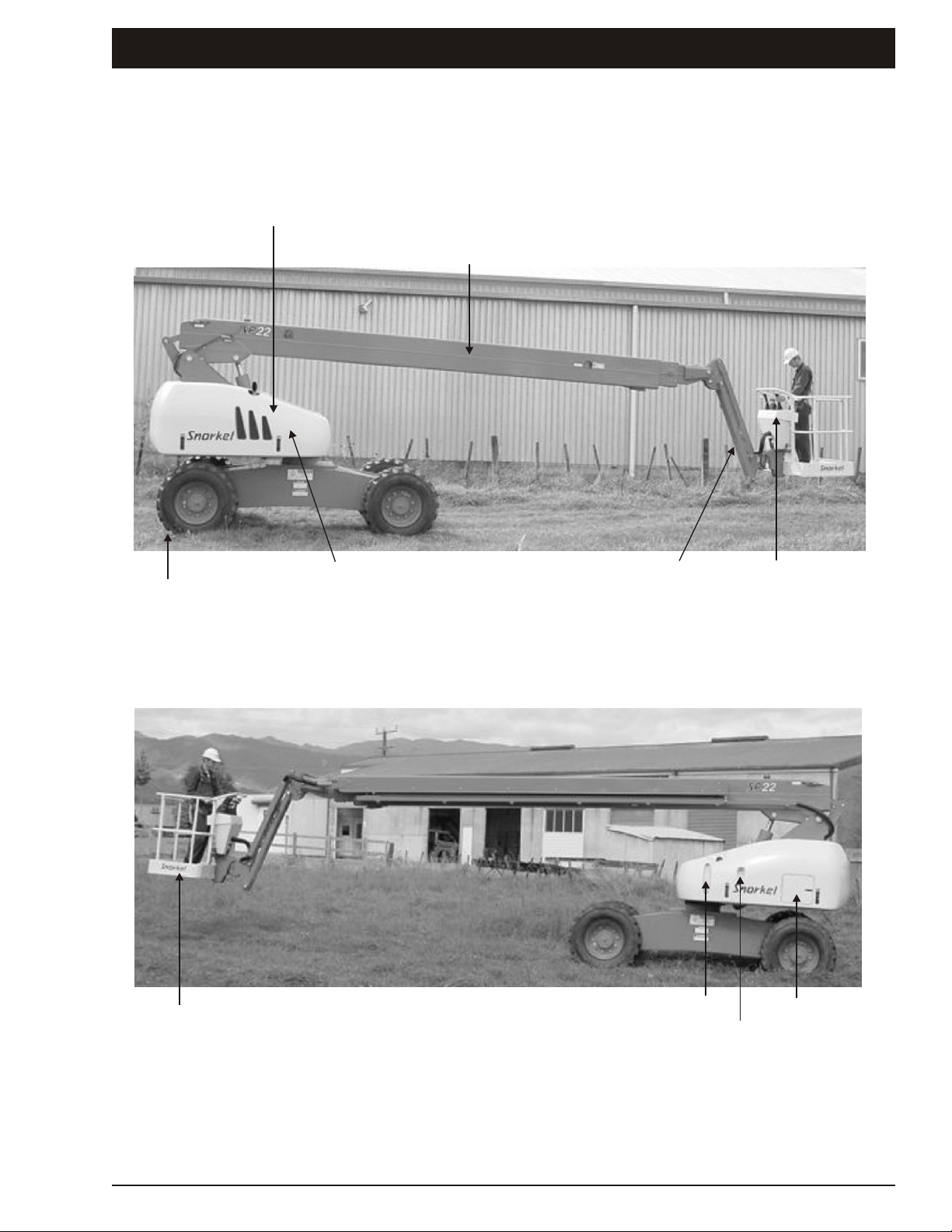
■
Hydraulic Oil Tank
Diesel Fuel Tank
Ground Controls
Main Boom
Engine Side Cover
Jib Boom
Serial Plate Under
Engine Cover
Steer Wheels
Platform
Platform Controls
Right Hand Side
Left Hand Side
Component Identification
Chapter 1. Specifications
SP20/SP22 – 11890A page 1 - 1
Page 10
Chapter 1. Specifications
16 15 14 13 12 11 10 9 8 7 6 5 4 3 2 1 0 -1 -2 -3
50 45 40 35 30 25 20 15 10 5 0 -5 -10
METRES
FEET
20
19
18
17
16
15
14
13
12
11
10
9
8
7
6
5
65
60
55
50
45
40
35
30
25
20
15
10
5
0
-5
-10
4
3
2
1
0
-1
-2
-3
METRES
FEET
21
68.8
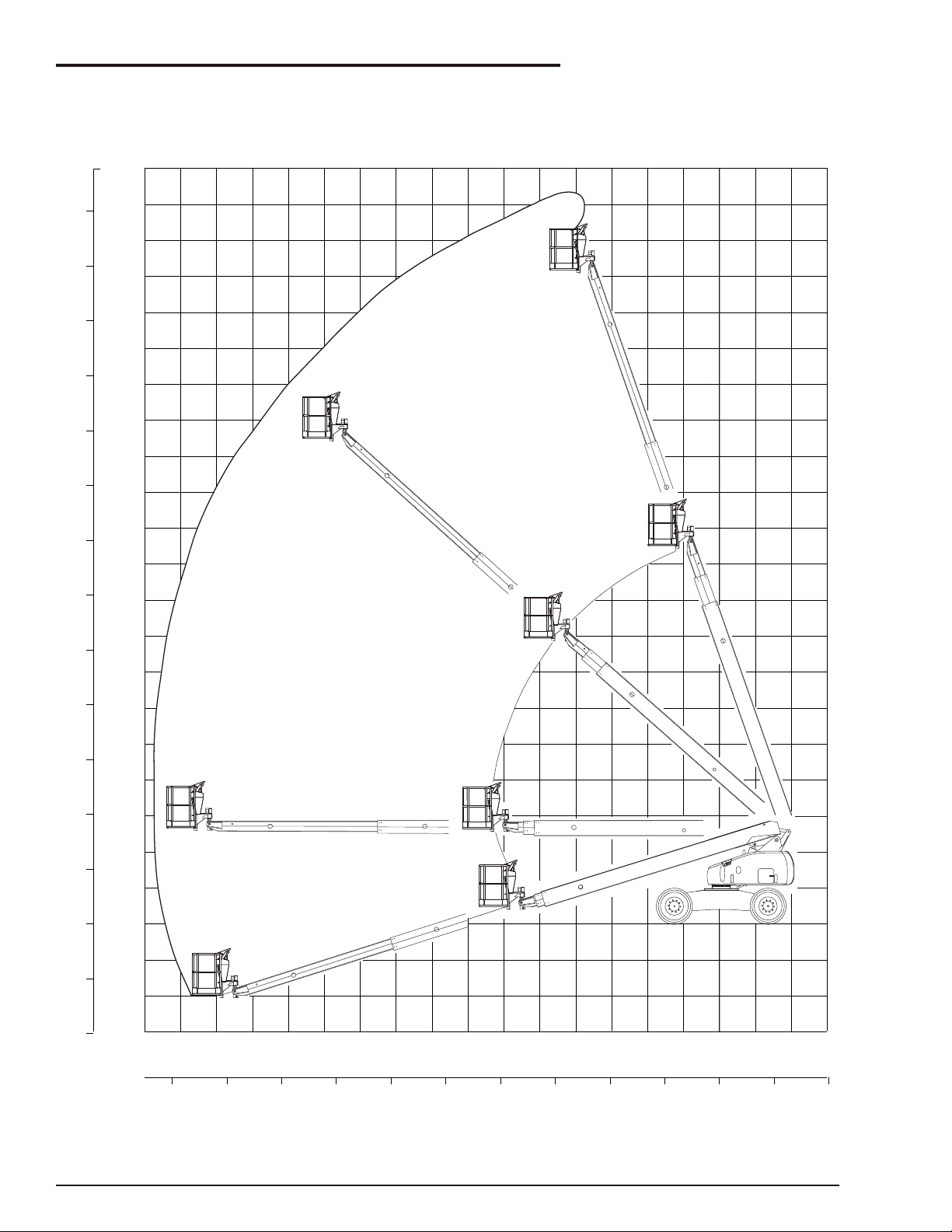
■
Working Envelope—SP20
page 1 - 2 SP20/SP22 – 11890A
Page 11
METRES
FEET
16 15 14 13 12 11 10 9 8 7 6 5 4 3 2 1 0 -1 -2 -31718
50 45 40 35 30 25 20 15 10 5 0 -5 -105560
METRES
19
18
17
16
15
14
13
12
11
10
9
8
7
6
5
4
3
2
1
0
-1
-2
-3
-4
20
21
22
65
60
55
50
45
40
35
30
25
20
15
10
5
0
-5
-10
FEET
70
72
-13
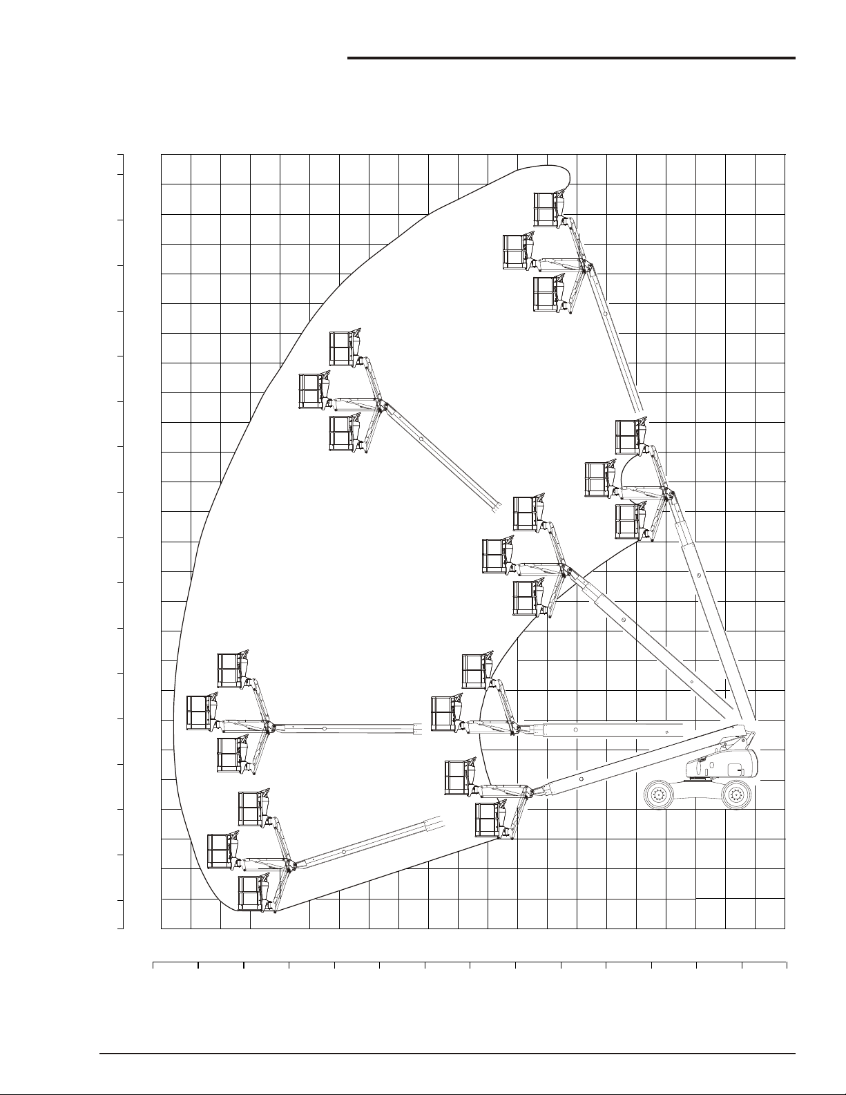
■
Working Envelope—SP22
Chapter 1. Specifications
SP20/SP22 – 11890A page 1 - 3
Page 12

Chapter 1. Specifications
■
General Specifications—SP20
Working height ...................20.3m (66’)
Maximum single wheel load ....5780kg (12716 lb)
Maximum platform height ...........18.3m (60’)
Horizontal outreach ...............15.8m (50’)
Turntable rotation .............360° continuous
Main boom
Articulation ....................-16° to +72°
Platform
Dimensions
Standard .........760 x 1830mm (30” x 72”)
Optional .........30² x 96² (76 cm x 244 cm)
Guardrail height .............1100mm (43.3”)
Rated work load..............227 kg (500 lb)
Rotation............................180°
Maximum number of occupants .......2 people
Cycle times
Turntable rotation ...............115/120 sec
Main boom
Up ..........................45/50 sec
Down ........................45/50 sec
Extend .......................65/70 sec
Retract.......................55/65 sec
Platform rotation ..................16/20 sec
Drive system
Standard ....................4-wheel drive
Steering system
Standard ....................2-wheel steer
Weight ...................10250kg (22550 lb)
Ground bearing strength
Minimum...................441kPa (64 psi)
Electrical system
Voltage.....12 V DC negative chassis ground
Source .....1 - 12 V 15 plate 600 CCA battery
Fluid recommended ........... distilled water
Hydraulic system
Maximum pressure .........3250 psi (224 bar)
Reservoir capacity ......100 litres (26.3 US gal)
System capacity .......129 litres (33.9 US gal)
Maximum operating temperature ...93°C(200°F)
Hydraulic fluid recommended
Shell Tellus T37 ........................
Engine..........................Deutz F4L
Optional .....................Cummins 4B
Fuel tank capacity........100 litres (26.3 US gal)
Ambient air temperature operating range
Celsius .....................-18°C to 43°C
Fahrenheit....................0°F to 110°F
Maximum wind speed
12.5m/sec ................45 km/h (28 mph)
Tires, 14ply
Foam filled ..................15 x 19.5 HD
Gradeability ..........................40%
Drive speed
High .....................3.2 km/h (2 mph)
Low ...................0.87 km/h (0.5 mph)
Turning radius, inside
Inside .......................3.8m (12’ 2”)
Outside........................6.1m (20’)
Tailswing
Stowed......................225mm (8.8”)
Overside ...................850mm (33.5”)
Stowed height ................2790mm (9’ 2”)
Stowed width .................2380mm (7’ 9”)
Stowed length ...............8790mm (28’ 9”)
Wheelbase...................2600mm (8’ 6”)
Ground clearance ..............370mm (14.5”)
Axle oscillation .........................7.8
0
page 1 - 4 SP20/SP22 – 11890A
Page 13

■
General Specifications—SP22
Working height .................21.8m (71’ 6’)
Chapter 1. Specifications
Axle oscillation .........................7.8
0
Maximum platform height ...........19.8m (65’)
Horizontal outreach .............17.6m (55’ 9”)
Turntable rotation .............360° continuous
Main boom
Articulation ....................-16° to +72°
Jib boom articulation .......-72 to + 72 degrees
Platform
Dimensions
Standard .........760 x 1830mm (30” x 72”)
Optional .........30² x 96² (76 cm x 244 cm)
Guardrail height .............1100mm (43.3”)
Rated work load..............227 kg (500 lb)
Rotation............................180°
Maximum number of occupants .......2 people
Cycle times
Turntable rotation ...............115/120 sec
Main boom
Up ..........................45/50 sec
Down ........................45/50 sec
Extend .......................65/70 sec
Retract.......................55/65 sec
Platform rotation ..................20/25 sec
Drive system
Standard ....................4-wheel drive
Steering system
Standard ....................2-wheel steer
Maximum single wheel load ....5960kg (13112 lb)
Weight ...................10894kg (23966 lb)
Ground bearing strength
Minimum...................537kPa (78 psi)
Electrical system
Voltage.....12 V DC negative chassis ground
Source .....1 - 12 V 15 plate 600 CCA battery
Fluid recommended ........... distilled water
Hydraulic system
Maximum pressure .........3250 psi (224 bar)
Reservoir capacity ......100 litres (26.3 US gal)
System capacity .......129 litres (33.9 US gal)
Maximum operating temperature ...93°C(200°F)
Hydraulic fluid recommended
Shell Tellus T37 ........................
Engine..........................Deutz F4L
Optional .....................Cummins 4B
Fuel tank capacity........100 litres (26.3 US gal)
Ambient air temperature operating range
Celsius .....................-18°C to 43°C
Fahrenheit....................0°F to 110°F
Maximum wind speed
12.5m/sec .................45 km/h (28 mph)
Tires, 14ply
Foam filled ..................15 x 19.5 HD
Gradeability ..........................40%
Drive speed
High .....................3.2 km/h (2 mph)
Low ...................0.87 km/h (0.5 mph)
Turning radius, inside
Inside ........................3.8m (12’2”)
Outside ........................6.1m (20’)
Tailswing
Stowed......................225mm (8.8”)
Overside ...................850mm (33.5”)
Stowed height ................2790mm (9’ 2”)
Stowed width .................2380mm (7’ 9”)
Stowed length ..............8207mm (26’ 11”)
Wheelbase...................2600mm (8’ 6”)
Ground clearance ..............370mm (14.5”)
SP20/SP22 – 11890A page 1 - 5
Page 14
Chapter 1. Specifications
Cummins Diesel Engine
Deutz Diesel Engine
11 - 4Q 99
11- 4Q 99
Manufacturing Plant Number
Sample Hose Code
Year of Manufacture
Manufacturing Period (i.e. 4th Quarter)
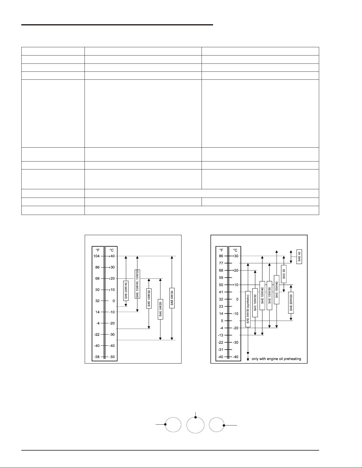
■
Engine Specifications
Engine Make Cummins Deutz
Model B3.3 F4L-1011
Horsepower 60 hp @ 2,500 rpm 53.5 hp @ 3000 rpm
Coolant Liquid (50% water 50% ethylene glycol) Air
Fuel
Type
Grade
Diesel
• ASTM No. 2 D
• Cetane # > 40
Diesel
• DIN 51 601
• BS 2869: A1 and A2
• For operating temperatures below 32°F (0°C)
use winterized No 2D.
Operating temperature 141°F to 211°F
Oil capacity 7l (7.3 US qt) 10l (10.5 US qt)
Oil grade API: CH-4
Oil viscosity
Oil filter capacity 0.5l (0.52 US qt) 0.5 l (0.52 US qt)
Running time
■
Engine Oil Viscosity
(60°C to 100°C)
See engine Oil Viscosity
One full tank of diesel will last for eight hours under normal working conditions
• ASTM D 975-81: 1-D
and 2-D
• W-F-800C: DF-A, DF-1
and DF-2.
172°F to 203°F
(78°C to 95°C)
API: CF-4
CG-4
CH-4
■
Hydraulic Hose Age
EN982 Clause 7.3.1 requires the manufacturing date of each hydraulic hose to be clearly visible on the
hose. Hoses used in production of this unit are manufactured by Parker and the manufacturing date is
present in a coded format. The key to decode the date format is as follows:
page 1 - 6 SP20/SP22 – 11890A
Page 15
Chapter 2. Safety
WARNING
Safety Rules
Electrocution Hazard
This machine is not insulated
DANGER
DANGER
All personnel shall carefully read, understand and follow all safety rules and operating instructions
before operating or performing maintenance on any Snorkel aerial work platform.
■
Electrocution Hazards
The ae rial plat form is made of metal com po nents
and is not in su lated. Re gard all con duc tors as en er gized. Do not op er ate out side dur ing a thun der storm. (See also Elec tri cal Haz ard sec tion at the
be gin ning of this man ual).
The aerial platform is not electrically
insulated. Death or serious injury can result
from contact with, or inadequate clearance
from, an energized conductor. Do not go
closer than the minimum safe approach
distance as defined by ANSI.
ANSI publications define minimum distances that
must be observed when working near bus bars and
energized power lines.
❑ Minimum Safe Approach Distance
Minimum safe approach distances to energized
power lines and their associated parts must be
observed while operating the aerial platform
■
Safety Overview
Knowledge of the information in this manual, and
proper training, provide a basis for safely operating
the aerial platform. Know the location of all controls
and how they operate to act quickly and
responsibly in an emergency.
Safety de vices re duce the like li hood of an ac ci dent. Never dis able, mod ify, or ig nore any safety
de vice. Safety alerts in this man ual in di cate sit u a tions where ac ci dents may oc cur.
If any mal func tion, haz ard or po ten tially un safe
con di tion re lat ing to ca pac ity, in tended use, or safe
op er a tion is sus pected, stop ae rial plat form op er a tion and seek as sis tance.
The op er a tor bears ul ti mate re spon si bil ity for fol low ing all man u fac turer’s in struc tions and warn ings, reg u la tions and safety rules of their em ployer
and/or any state or fed eral law.
❑ Use of the Aerial Work Platform
The SP20/SP22 aerial work platform is intended to
lift personnel and their tools, as well as the material
used for the job.
It is designed for repair and assembly jobs and
Op er a tors must check lo cal power
reg u la tions be fore us ing the SP unit near
power lines.
THIS AERIAL WORK PLATFORM IS NOT
INSULATED! For this reason it is imperative to
keep a safe distance from live parts of electrical
equipment. (See Electrical Hazard Section at the
beginning of this manual)
SP20/SP22 – 11890A page 2 - 1
assignments at overhead workplaces (ceilings,
cranes, roof structures, buildings etc.).
All other uses of the aerial work platform are
prohibited!
Exceeding the specified permissible maximum
load is pro hib ited! See Spec i fi ca tions Chap ter
page for de tails.
Page 16

Chapter 2. Safety
CAUTION
The use and operation of the aerial work platform
as a lifting tool or crane (lifting of loads from below
upwards or from a height to the ground) is
prohibited!
NEVER exceed the manual force allowed for this
machine. See Special Limitations on page of this
chapter for details.
DISTRIBUTE all platform loads evenly on the
platform.
NEVER operate the machine without first
surveying the work area for surface hazards such
as holes, drop-offs bumps, curbs, or debris, and
avoiding them.
OPERATE the machine only on surfaces capable
of supporting wheel loads.
NEVER operate the machine when wind speeds
exceed this machines rating. See Beaufort Scale
on page 5 of this chapter for details.
IN CASE OF EMERGENCY push the
EMERGENCY STOP to deactivate all powered
functions.
Climbing up the railing of the platform, standing on
or stepping from the platform onto buildings, steel
or prefab concrete structures, etc., is prohibited!
NEVER use a machine that is damaged, not
functioning properly, or has damaged or missing
labels.
NEVER charge batteries near sparks or open
flames. Charging batteries emit explosive
hydrogen gas.
Modifications to the aerial work platform are
prohibited or permissible only with the approval of
Snorkel.
AFTER USE, secure the SP20/SP22 from
unauthorized use by turning the key switches off
and removing the key.
■
Safe Operation
The following safety information is vitally important
for safe operation of the SP. Failure to follow these
instructions can result in personal injury or DEATH.
❑ Pre-start Inspection
At the start of each work shift, the SP shall be given
a visual inspection and function test. See the
Pre-operational Inspection chapter 7, in this
manual for a list of items to inspect and test.
IF AN ALARM SOUNDS while the platform is
elevated, STOP, and carefully lower the platform.
Move the machine to a firm, level surface.
Bypassing any safety equipment is prohibited
and presents a danger for the persons on the aerial
work platform and its working range.
Dismantling the entry gate or other railing
components is prohibited! Always make certain
that the entry gate is closed and securely locked!
It is prohibited to keep the entry gate in an open
position (held open with tie-straps) when the
platform is raised!
Extending the height or the range of the platform by
placing ladders, scaffolds, or similar devices on the
platform is prohibited!
NEVER perform service on the machine while the
platform is elevated without blocking the elevating
assembly.
INSPECT the machine thoroughly for cracked
welds, loose or missing hardware, hydraulic leaks,
loose wire connections, and damaged cables
before using.
VERIFY that all labels are in place and legible
before using the machine.
DO NOT op er ate the SP un less you are
trained and au tho rized, un der stand the
op er a tion char ac ter is tics of the SP, and
have in spected and tested all func tions to be
sure they are in proper work ing or der.
❑ Work Place Inspection and Practices
Do not use the SP as a ground for welding. Ground
to the work piece.
Before the SP is used, and during use, check the
area in which the SP is to be used for possible
hazards such as, but not limited to:
●
Drop-offs or holes.
●
Side slopes.
●
Bumps and floor obstructions.
●
Debris.
●
Overhead obstructions and electrical
conductors.
●
Hazardous locations.
●
Inadequate surface and support to withstand
all load forces imposed by the aerial platform
in all operating configurations.
●
Wind and weather conditions.
●
Presence of unauthorized persons.
page 2 - 2 SP20/SP22 – 11890A
Page 17

Chapter 2. Safety
DANGER
DANGER
●
Other possible unsafe conditions.
A recommended safety practice is to have
personnel that are trained in the operation of the
emergency controls working in the immediate area
of the SP to assist the platform operator in the
event of an emergency to:
●
Help in case of an emergency
●
Operate emergency controls as required
●
Watch for loss of control by platform operator
●
Warn the operator of any obstructions or
hazards that may not be obvious to them
●
Watch for soft terrain, sloping surfaces,
drop-offs, etc. where stability could be
jeopardized
●
Watch for bystanders and never allow
anyone to be under, or to reach through the
booms while operating the aerial platform
Pinch points may exist between moving
components. Death or serious injury can
result from becoming trapped between
components, buildings, structures or other
obstacles. Make sure there is sufficient
clearance around the machine before moving
the chassis, booms, or platform. Allow
sufficient room and time to stop movement to
avoid contact with structures or other
hazards.
When moving the platform, check the clearance
around the SP to avoid contact with structures or
other hazards. Always look in the direction of
motion.
Keep ground personnel from under the platform
when the platform is raised.
NOTE
When low er ing the plat form, pay spe cial
at ten tion to see that there are no peo ple near or
ap proach ing the ma chine. Should this be the
case, in ter rupt the low er ing pro cess
im me di ately. Con tinue low er ing the plat form
only when any peo ple who were too near the
ma chine are out of its op er at ing per im e ter.
Secure all accessories, containers, tools, and
other materials in the platform to prevent them from
accidentally falling or being kicked off the platform.
DO NOT engage in any form of horseplay or stunt
driving while operating the SP.
DO NOT permit riders on the machine anyplace
other than on the platform.
Remove all loose objects stored in or on the
machine, particularly in the platform. Remove all
objects which do not belong in or on the machine.
When other moving equipment is in the area, take
special precautions to comply with local
regulations regarding warnings.
Never steady the platform by positioning it against
another platform.
DO NOT op er ate an SP that is not func tion ing
prop erly, or has been dam aged, un til the ma chine
has been re paired by a qual i fied main te nance
per son.
DO NOT operate a SP that does not have all its
decals and placards attached and legible.
Drive the machine with care and at speeds
compatible with conditions. Use extra caution
when driving over rough ground, on slopes, and
when turning.
Know and understand the job site traffic-flow
patterns and obey the flag-men, road signs, and
signals.
Watch for bystanders and never allow anyone to be
under, or to reach through, the machine and its
equipment while operating.
Use the recommended transport device when
loading the machine.
❑ Electrocution
The SP is an all metal, NON-INSULATED, aerial
work platform. DO NOT operate it near
ELECTRICAL conductors. Regard all conductors
as being energized.
DO NOT operate outside during a thunderstorm.
❑ Tipover and Falling Hazards
DO NOT raise the platform if the SP is on soft
ground. Operate the platform only on a firm surface
capable of withstanding all load forces imposed by
the aerial platform in all operating conditions.
The ae rial plat form can tip over if it be comes
un sta ble. Death or se ri ous in jury can re sult
from a tip-over ac ci dent. Do not drive or
po si tion the ae rial plat form for el e vated use
near any drop-off, hole, slope, soft or un even
ground, or other tip-over haz ard.
Care shall be taken to prevent rope, electric cords,
and hoses, etc., from becoming entangled in the
aerial platform.
SP20/SP22 – 11890A page 2 - 3
Page 18

Chapter 2. Safety
DANGER
DANGER
DANGER
❑ Crushing
Always look in the direction of travel. Avoid
overhead obstructions.
Make sure the area below the platform is free of
personnel before lowering.
■
Special Limitations
❑ Manual Force
Manual force is the force applied by the occupants
to objects such as walls or other structures outside
the work area.
The maximum allowable manual force is limited to
200 N (45 lbs.) of force per occupant, with a
maximum of 400 N (90 lbs.) for two or more
occupants.
DO NOT ex ceed the max i mum amount of
man ual force for this ma chine.
■
General Safety Precautions
❑ Personnel Precautions
If you encounter any suspected malfunction of the
aerial platform, or any hazard or potentially unsafe
condition relating to capacity, intended use, or safe
operation, cease operation and seek assistance
from management.
❑ Operator General Precautions
Make sure that all protective guards, cowlings, and
doors are in place and secure.
Be sure the guardrail system, including the gate, is
in place and secure.
❑ Mounting and Dismounting Precautions
Use three points of support when getting on or off
the platform (two hands and one foot or a similar set
of points). Keep the platform clean.
DO NOT jump off the machine.
DO NOT dismount while the machine is in motion.
❑ Starting and Stopping Precautions
DO NOT start un til all per son nel are clearly away
from the ma chine.
Before leaving the operators station, place the
machine in the stowed position.
When leaving the machine parked or unattended,
remove the starter key from the Key switch and set
the Battery switch to off.
❑ Operating Precautions
When parts or components are replaced, they shall
be identical or equivalent to original Snorkel parts
or components.
❑ Operator Maintenance Precautions
❑ Electrical System
Charge batteries in a well-ventilated area free of
flame, sparks, or other hazards that might cause
fire or explosion.
Batteries give off hydrogen and oxygen that
can combine explosively. Death or serious
injury can result from a chemical explosion.
Do not smoke or permit open flames or
sparks when checking the batteries.
Battery acid can damage the skin and eyes.
Serious infection or reaction can result if
medical treatment is not given immediately.
Wear face and eye protection when working
near the batteries.
Batteries contain sulfuric acid that can damage
your eyes or skin on contact. Wear a face shield,
rubber gloves, and protective clothing when
working around batteries. If acid contacts your
eyes, flush immediately with clear water and get
medical attention. If acid contacts your skin, wash
off immediately with clear water.
❑ Hydraulic System
The hydraulic system contains hoses with
hydraulic fluid under pressure.
DO NOT use your hand to search for
hy drau lic oil leaks. High pres sure hy drau lic
oil can eas ily cut and pen e trate your skin a
very se ri ous in jury that re quires im me di ate
at ten tion by a med i cal spe cial ist trained in
that type of in jury. Use a piece of card board
or wood to search for hy drau lic oil leaks.
DO NOT attempt repairs unless you are trained.
Refer to manuals and experienced repair
personnel for help.
page 2 - 4 SP20/SP22 – 11890A
Page 19
Chapter 2. Safety
CAUTION
BEAUFORT
SCALE
WIND SPEED
GROUND CONDITIONS
m/s km/h ft/s mph
3 3.4~5.4 12.5~19.4 11.5~17.75 5~12.0 Papers and thin branches move, flags wave.
4 5.4~8.0 19.4~28.8 17.75~26.25 12.0~18 Dust is raised, paper whirls up, and small branches sway.
5 8.0~10.8 28.8~38.9 26.25~35.5 18~24.25 Shrubs with leaves start swaying. Wave crests are apparent in ponds
or swamps.
6 10.8~13.9 38.9~50.0 35.5~45.5 24.5~31 Tree branches move. Power lines whistle. It is difficult to open an umbrella.
7 13.9~17.2 50.0~61.9 45.5~56.5 31~38.5 Whole trees sway. It is difficult to walk against the wind.
■
Beaufort Scale
Never operate an SP20/SP22 when wind speeds exceed 45 km/h (28 mph) [Beaufort scale6]
❑ Fuel Handling Precautions
DO NOT smoke or permit open flames while fueling
or near fueling operations.
Never remove the fuel cap or refuel a gasoline
engine while the engine is running or hot. Never
allow fuel to spill on hot machine components.
Maintain control of the fuel filler nozzle when filling
the tank.
DO NOT fill the fuel tank to capacity. Allow room for
expansion.
Clean up spilled fuel immediately.
Tighten the fuel tank cap securely. If the fuel cap is
lost, replace it with an approved cap from Snorkel.
Use of a non-approved cap without proper venting
may result in pressurization of the tank.
Never use fuel for cleaning purposes.
For diesel engines, use the correct fuel grade for
the operating season.
■
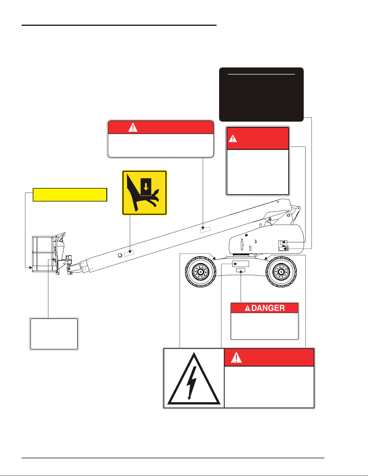
Safety Decals and Placards
There are several safety decals and placards on
the SP. Their locations and descriptions are shown
in this section. Take time to study them.
You MUST replace a decal or placard if it is
damaged, missing, or cannot be read. If it is on a
part that is replaced, make sure a new decal or
placard is installed on the replaced part. See your
Snorkel dealer for new decals and placards.
NOTE
Refer to Placards and Decals Inspection Chart and
Drawing in the Pre-operational Inspection and
Maintenance chapter , for part numbers, location,
and required quantities of all placards and decals..
Be sure that all the safety de cals and
plac ards on the SP are leg i ble. Clean or
re place them if you can not read the words or
see the pic tures. Clean with soap & wa ter
and a soft cloth. Do not use sol vents.
SP20/SP22 – 11890A page 2 - 5
Page 20
Chapter 2. Safety
This machine is equipped with foam filled or solid tires, wheel weight is
critical for stability.
To prevent machine tip over, replace tires with factory approved foam
filled or solid tires ONLY.
DO NOT attempt to inflate foam filled or solid tires.
0073298
MACHINE TIPOVER HAZARD
DEATH or serious injury can result if machine tips over.
0190989E
YOU MUST NOT OPERATE THIS DEVICE UNLESS:
AN UNTRAINED OPERATOR SUBJECTS HIMSELF AND OTHERS TO
DEATH OR SERIOUS INJURY.
0323897
1.
2.
YOU HAVE BEEN TRAINED IN THE SAFE OPERATION OF THIS
DEVICE AND HHHH
YOU KNOW AND FOLLOW THE SAFETY AND OPERATING
RECOMMENDATIONS CONTAINED IN THE MANUFACTURER'S
MANUALS, YOUR EMPLOYER'S WORK RULES, AND APPLICABLE GOVERNMENTAL REGULATIONS. HHHHHHHH
DANGER
300699
INSPECT AND/OR TEST THE FOLLOWING DAILY
OR AT THE BEGINNING OF EACH SHIFT
OPERATORS CHECKLIST
1. OPERATING AND EMERGENCY CONTROLS.
2. SAFETY DEVICES.
3. PERSONAL PROTECTIVE DEVICES.
4. HOSES, FITTINGS AND VALVES FOR LEAKS.
5. CABLES AND WI RING HARNESS.
6. LOOSE OR MISSING PARTS.
7. TIRES AND WHEELS.
8. PLACARDS, WARNINGS, CONTROL MARKINGS
AND OPERATING MANUAL(S).
9. GUARDRAIL SYSTEM.
10. OIL LEVELS.
11. BATTERY FLUI D LEVEL.
DANGER
DO NOT ALTER OR DISABLE
LIMIT SWITCHES, SAFETY
SWITCHES, OR INTERLOCKS.
451986
DANGER
ELECTROCUTION
HAZARD
KEEP CLEAR
Death or serious injury can result from touching
this machine if this machine is in contact with
electrical power lines or apparatus.
0323896
Attach lanyard
of fall restraint
to loop below
0150448
SWL
227
KG
0323896
300699
0150448
0190989E
0073298
2025-227
0323897
451986
■
Safety Placards and Decals Drawing 1
page 2 - 6 SP20/SP22 – 11890A
Page 21
■
DANGER
DO NOT ALTER OR DISABLE
LIMIT SWITCHES, SAFETY
SWITCHES, OR INTERLOCKS.
451986
0190989E
DANGER
ELECTROCUTION
HAZARD
KEEP CLEAR
Death or serious injury can result from touching
this machine if this machine is in contact with
electrical power lines or apparatus.
0323896
This machine is equipped with foam filled or solid tires, wheel weight is
critical for stability.
To prevent machine tip over, replace tires with factory approved foam
filled or solid tires ONLY.
DO NOT attempt to inflate foam filled or solid tires.
0073298
MACHINE TIPOVER HAZARD
DEATH or serious injury can result if machine tips over.
0072277
TORQUE
200-225 Ft. Lbs.
·
271-305 N m
DANGER
ELECTROCUTION
HAZARD
THIS MACHINE IS NOT
ELECTRICALLY INSULATED.
0323899
Death or serious injury can result from
contact or inadequate clearance to
electrical power lines and apparatus.
Maintain 10 feet minimum clearance
from electrical power lines and
apparatus.
Allow for sway, rock, and sag.
CAUTION
DO NOT USE BOOM TO LIFT OR PUSH MACHINE
0073668
YOU MUST NOT OPERATE THIS DEVICE UNLESS:
AN UNTRAINED OPERATOR SUBJECTS HIMSELF AND OTHERS TO
DEATH OR SERIOUS INJURY.
0323897
1.
2.
YOU HAVE BEEN TRAINED IN THE SAFE OPERATION OF THIS
DEVICE AND HHHH
YOU KNOW AND FOLLOW THE SAFETY AND OPERATING
RECOMMENDATIONS CONTAINED IN THE MANUFACTURER'S
MANUALS, YOUR EMPLOYER'S WORK RULES, AND APPLICABLE GOVERNMENTAL REGULATIONS. HHHHHHHH
DANGER
11868
0323896
0323899
0073298
11896
0072277
0190989E
99228
451986
0323897
0073668
SAFETY BELTS WITH
CAUTION
SHOULDER STRAPS OR
SAFETY HARNESS ARE
TO BE USED
SAFETY BELTS WITH
9928
ENGINE SWING TRAY LATCH
ENSURE TRAY IS PROPERLY LATCHED AND
SECURITY PIN IS IN PLACE BEFORE RUNNING
ENGINE.
ALWAYS ENSURE PIVOT LOCK IS ENGAGED
WHEN ENGINE TRAY IS IN OPEN POSITION
WARNING
11868
CAUTION
Do not remove any weight from this machine Any weight added must be
distributed equally on each axle. Proper stability and axle weights of
this machine are based on the platform size shown above.
SERIAL
NUMBER
MODEL
NUMBER
MAXIMUM
MACHINE
WEIGHT
lbs
kg
MAXIMUM
WHEEL
LOAD
lbs
kg
MONTH / YEAR
OF MANUFACTURE
SLOPE SENSOR
ALARM SETTING
deg
MAXIMUM
PLATFORM
HEIGHT
ft
m
MACHINERY DIRECTIVE 98/37/CEE
PLATFORM
CAPACITY
MAXIMUM
ALLOWABLE
MANUAL FORCE
(SIDE PULL)
lbs
N
MAXIMUM
ALLOWABLE
WIND SPEED
mi/h
m/s
OUTRIGGER
LOAD
ft
m
11896
36 Bruce Road
Levin 5500 - New Zealand
= 227 kg = 2 PERSONS + ADD. LOAD
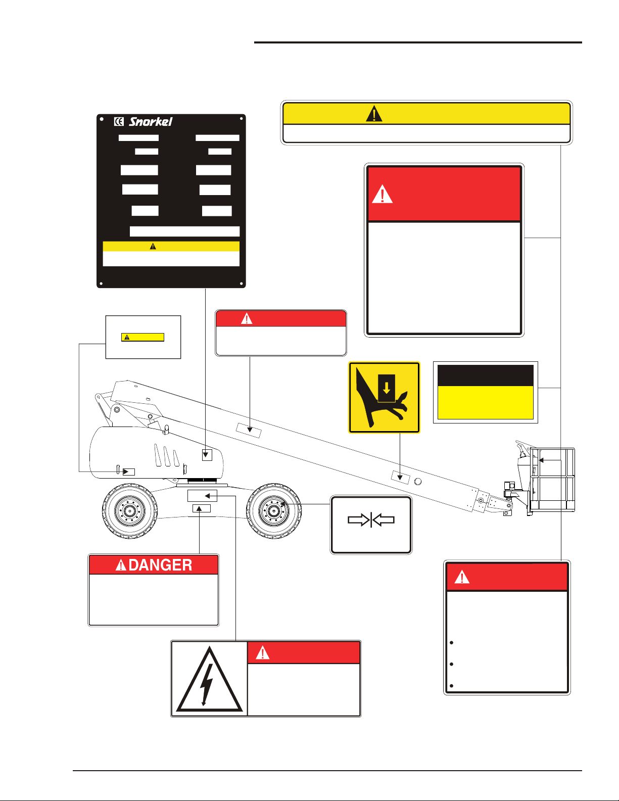
Safety Placards and Decals Drawing 2
Chapter 2. Safety
SP20/SP22 – 11890A page 2 - 7
Page 22

Page 23

Chapter 3. Safety Devices
DANGER
This aerial platform is manufactured with safety
devices, placards, and decals to reduce the
likelihood of an accident. For the safety of all
personnel, do not disable, modify, or ignore any
safety device. Safety devices are included in the
Pre-operational Inspection.
The potential for an accident increases when
safety devices do not function properly.
Death or serious injury can result from such
accidents. Do not alter, disable, or override
any safety device.
If any safety devices are defective, remove the
aerial platform from service until qualified
maintenance personnel can make repairs.
■
Emergency Stop Controls
There is an emergency stop control at the lower
and upper controls.
❑ At ground control box
Press the large red EMERGENCY STOP (re fer to
Fig ure 3.1) but ton in and the en tire ma chine
stops, the en gine turns off, and noth ing moves.
This but ton must be out (on) to con trol the SP (pull
the button and it will pop out).
This button must be out (on) to control the SP from
the platform (pull the button and it will pop out).
Figure 3.2—Platform Controls
■
Emergency Power System
The emergency power system includes a back-up
pump, motor, and battery. Use this system to
operate the boom and turntable functions to lower
the platform if the main power system fails due to
engine or pump failure.
Operate the emergency power switch (refer to
Figure 3.1 and 3.2) to activate the emergency
power system.
Figure 3.1—Ground Controls
NOTE
The lower controls override the upper controls. If
the upper control emergency stop button is
engaged the lower controls can still be used to
operate the aerial platform.
❑ At platform control box
Press the large red EMERGENCY STOP (refer to
Figure 3.2) button in and the entire machine
stops, the engine turns off, and nothing moves.
The length of time the pump can be operated
depends on the capacity of the battery.
■
Manual Lowering Knob
The manual emergency lowering knob (refer to
Figure 3.3) may be used to lower the booms if the
engine will not start and the emergency power
system will not work. The knob is located on the
base control panel.
Figure 3.3—Emergency Lowering Knob
SP20/SP22 – 11890A page 3 - 1
Page 24

Chapter 3. Safety Devices
DANGER
NOTE
CEE COMPLIANCE
There is an additional emergency bleed down knob
located at the base of the main lift cylinder.
■
Platform Foot Switch
The platform foot switch (refer to Figure 3.4)
prevents boom and platform movement if a control
on the upper control panel is accidentally moved.
All personnel in the platform must connect their fall
restraint device to a lanyard anchor before raising
the platform. Do not use the aerial platform for
personal fall arrest anchorage.
■
Horn
The horn (refer to Figure 3.2) may be used to
warn personnel on the ground. The horn is
operational when the machine is set up for
operation from the upper controls.
■
Tilt Alarm
If the aerial platform chassis is out of level more
than five degrees when the main boom is raised or
extended, an alarm will sound.
The aerial platform can tip over if it becomes
unstable. Death or serious injury can result
from a tip-over accident. Do not drive or
position the aerial platform for elevated use
near any drop-off, hole, slope, soft or uneven
ground, or other tip-over hazard.
Figure 3.4—Platform
Step down on the platform foot switch to activate
the boom and platform controls.
■
Guardrails
The guardrail system includes a top rail, mid rail,
and toeboards around the sides of the platform
(refer to Figure 3.4).
A gravity gate or an optional swinging gate allows
for access to the platform (refer to Figure 3.4).
The swinging gate closes automatically after
entering or exiting the platform. The gate is part of
the guardrail system and must be securely
fastened after entering the platform.
■
Lanyard Anchors
Two lanyard anchors for fall restraint anchorage
are provided below the upper controls at the front of
the platform (refer to Figure 3.4).
NOTE
The lanyard anchors are not for lifting or tying the
machine down.
Completely lower and retract the main boom and
then drive to a level surface when the tilt alarm
sounds.
The tilt alarm is for added protection and does not
justify operating on anything other than firm, flat,
level surfaces.
■
All Motion Alarm
An all motion alarm is be provided on the machine.
When boom or drive control is moved out of neutral,
the alarm sounds to warn personnel in the work
area to stand clear.
■
Flashing Light
An amber flashing light is located on the top of the
boom. The flashing light warns personnel that the
aerial platform is in the area.
The light flashes at about one flash per second
when the engine is running.
■
Driving Lights
Optional headlights and blinking tail lights may be
installed on the machine. The headlights are 30
watts each and are located on the top of the front
cowling. The tail lights are 25 watts each and are
mounted on the sides of the rear cowling.
Driving lights help improve visibility while driving
the aerial platform and help others see it too.
Driving lights are not for driving on public
roadways.
page 3 - 2 SP20/SP22 – 11890A
Page 25

■
Platform Working Lights
Optional platform working lights may be located on
the top rail of the platform, one on each side of the
upper control panel.
Use the platform lights to improve visibility while
working aloft in dimly lit areas. Do not use the
platform work lights to drive on public roadways.
Chapter 3. Safety Devices
SP20/SP22 – 11890A page 3 - 3
Page 26

Page 27

Chapter 4. Gauges and Displays
The aerial platform is equipped with several
gauges to monitor the condition of the machine
before and during operation.
■
Hour Meter
The hour meter is located at the lower controls
(refer to Figure 4.1). It measures the accumulated
operating time.
■
Fuel
The fuel tank (refer to Figure 4.3). Is ‘see through’
and this allows the operator to quickly gauge the
amount of fuel.
Figure 4.3—Diesel Fuel Gauge
NOTE
Do not run a diesel fuel tank empty. Air in the fuel
line makes the engine hard to start.
Figure 4.1—Ground Controls
■
Engine Air Filter Gauge
The air filter gauge is located under the engine
cowling (refer to Figure 4.2). The gauge measures
the air pressure between the intake manifold and
the air filter. The yellow indicator disk raises toward
the red area of the sight glass as the filter clogs.
The indicator disk stays at its highest setting and
does not go to the bottom of the sight glass when
the engine is turned off. When the disk reaches the
red area, it’s time to change the air filter.
■
Engine Oil
The engine oil level is measured with a dipstick. Oil
sump and filter capacities in the engine
specification charts are approximate. The dipstick
is the only way to accurately determine the engine
oil level. The engine oil level should always be in
the cross-hatched area of the dipstick.
The dipstick on a Deutz engine is located behind
the door on the right side of the turntable (refer to
Figure 4.4).
Figure 4.2 Deutz Air Filter Gauge
The dipstick on a Cummins engine is located
behind the door on the right side of the turntable
(refer to Figure 4.5).
SP20/SP22 – 11890A page 4 - 1
Figure 4.4—Deutz Engine Dipstick
Page 28

Chapter 4. Gauges and Displays
Figure 4.5—Cummins Engine Dipstick
■
Hydraulic Fluid Filter Gauge
The fluid filter gauge (refer to Figure 4.6) is located
next to the filter under the cover on the left side of the
turntable. The gauge indicates the condition of the
filter. When the needle on the gauge is in the red
zone, it is time to change the filter.
Figure 4.6—Fluid Filter Gauge
page 4 - 2 SP20/SP22 – 11890A
Page 29

Chapter 5. Shut-offs and Circuit Breakers
■
Automatic Shut-offs
❑ Engine temperature (Cummins engine)
There is a temperature sensor in the engine. It
measures the temperature of the antifreeze-water
mixture as the mixture leaves the top of the radiator
and enters the top of the engine.
If the temperature reaches 2100F (990C) an alarm
sounds. If the temperature continues to rise, the
engine shuts off when the temperature reaches
2300F (1100C).
The engine will not restart until the temperature
drops below 2100F (990C).
❑ Engine temperature (Deutz engine)
The Deutz engine is oil cooled therefore it is the oil
temperature that is monitored.
Should the engine oil temperature exceed 1300 C
the engine will shut down automatically.
It will restart but will be shut down again unless the
oil temperature returns to normal.
❑ Engine oil pressure
There is an oil pressure sensor in the engine. It
measures the engine oil pressure at the oil filter.
If the pressure falls below a safe operating value
the engine shuts off.
The engine will restart with low pressure but it will
only run a few seconds before it automatically
shuts off again.
❑ Dynamic brakes
When you drive an SP down a slope, if the SP
begins to coast (outrun the drive motors) the
hydraulic system “senses” the coasting condition.
Figure 5.1—Axle Lockout Indicator Light
■
Circuit Breakers
❑ Main circuit breakers
There are three circuit breakers, on the SP. These
are located inside the lower control box (Refer to
Figure 5.2). Their purpose is to protect the
electrical circuits from electrical overloads. When a
circuit breaker trips (pops out) push it back in then
attempt to use the SP.
If the circuit breaker trips a second time, take the
SP out of service and refer the problem to a
qualified trained service technician for repair.
The hydraulic drive motors then become hydraulic
brakes and the SR is slowed. This action prevents
SP’s from speeding down grades.
❑ Platform height vs. drive speed
When the platform is raised above horizontal the
drive speed is limited to its slowest speed and the
engine revs are also automatically lowered.
❑ Axle lockout
The articulating axle will automatically “lock” when
the boom is extended beyond 50% and the column
is slewed out over the side of the base.There is a
warning light in the platform control box (Refer to
Figure 5.1) that indicates when the axle is in the
locked position.
SP20/SP22 – 11890A page 5 - 1
❑ RCD / ELCB
The RCD (Residual Current Device) is located at
the ground and will protect against short circuits to
earth (Refer to Figure 5.3). When there is a short
circuit the RCD will shut down the 230v AC power
to the platform outlet.
Figure 5.2—Circuit Breakers
Page 30

Chapter 5. Shut-offs and Circuit Breakers
To reset the outlet disconnect the power tool lead
from the platform box and reset the RCD at the
ground.
If the problem persists call a trained service
technician.
Figure 5.3—RCD / ELCB
page 5 - 2 SP20/SP22 – 11890A
Page 31

Chapter 6. Controls
CAUTION
Controls to position the platform are located on the
lower control panel on the turntable and on the
upper control panel in the platform. Drive controls
are located on the upper control panel only.
■
Chassis Controls
❑ Battery Disconnect Switch
The battery disconnect switch is located under the
cover on the right side of the turntable (refer to
Figure 5.1)
The battery disconnect removes electrical power
from all electrically controlled functions when in the
off position. Place the switch in the on position to
operate any electrically controlled function.
●
Hour meter
●
Manual control levers for all functions
Figure 5.2—Ground Controls
❑ Master Switch
The master switch works like an automobile
ignition switch. Hold it at start until the engine
starts, then release it to on. If the engine dies, the
key must be turned to off before it will go back to
start.
Figure 5.1—Battery Disconnect Switch
Only authorized personnel should operate
the aerial platform. Unqualified personnel
may cause injury to coworkers or property
damage. Lock the battery disconnect switch
in the off position before leaving the aerial
platform unattended.
Lock the battery disconnect switch in the off
position to prevent unauthorized use of the aerial
platform.
■
Ground Controls
The lower controls (refer to Figure 5.2) are located
on the right side of the turntable. Boom and
platform functions can be operated from the lower
controls. The following are located on the lower
control panel.
●
Master key switch
●
Emergency stop switch
●
Ground/platform select switch
●
Emergency power switch
❑ Emergency Stop
The emergency stop is a two-position, red button
on the front of the lower control panel. Push the
button in to disconnect power to all control circuits
at the lower controls.
❑ Ground Operation
Switch to ground operation to operate aerial
platform functions from the lower controls.
❑ Emergency Power
Press the emergency power switch to operate
aerial platform functions using the emergency
power system.
NOTE
The emergency power system is for lowering the
platform during an emergency and is not intended
for normal machine operation.
SP20/SP22 – 11890A page 6 - 1
Page 32

Chapter 6. Controls
NOTE
CEE COMPLIANCE
There are two changes to the Ground Control box
to ensure compliance with Machinery Directive
98/37/CEE
1. Key start switch is replaced with a 3 position
switch the same as the Platform control
station.
2. The Ground/Platform selector is changed to
a key type selector with the key removable in
each position.
■
Platform Controls
The upper controls (refer to Figure5.3 and 5.4) are
located on the control box at the platform. Boom,
platform, and drive functions can be operated from
the upper controls. The following controls are
located on the upper control panel.
●
Emergency stop button
●
Start switch
●
Boom and platform joysticks
●
Drive and steer joystick
●
High range switch
●
Horn button
●
Emergency power switch
●
High revs switch
●
Platform rotate switch SP22 only
Figure 5.4— Platform Controls, SP22
❑ Emergency Stop Button
The emergency stop is a two-position, red push
button on the top of the upper control panel. Push
the button in to disconnect power to all control
circuits at the upper controls. Pull the button out to
restore power.
NOTE
The lower controls override the upper controls. If
the upper control emergency stop button is
engaged the lower controls can still be used to
operate the aerial platform.
Push the emergency stop button in when the upper
controls are not in use to protect against
unintentional platform operation.
❑ Component Select Switches
The following aerial platform components may be
selected from the upper control panel.
●
Platform rotate - SP22 only (refer to item
Figure 5.4)
Operate the appropriate switch to select a function.
❑ Boom and Platform Joystick
The boom and platform joysticks (refer to Figure
5.3 and 5.4) controls movement of the selected
component.
Movement of the joystick in a given direction
produces a corresponding movement of the aerial
platform.
❑ Drive and Steer Joystick
Figure 5.3—Platform Controls, SP20
page 6 - 2 SP20/SP22 – 11890A
The drive and steer joystick (refer to Figures 5.3
and 5.4) controls drive forward and reverse, and
Page 33

steer right and left. The steering and drive functions
may be operated simultaneously.
Movement of the joystick in a given direction
produces a corresponding movement of the aerial
platform.
NOTE
The steering wheels are not self-centering. Set the
steering wheels straight ahead after completing a
turn.
❑ High Range Switch
The high range button is on the upper right side of
the upper control panel.
Normal operation of the drive wheels is with low
speed and high torque. Press the range button to
change the drive system to high speed and low
torque operation.
❑ Horn Button
The horn button is on the right side of the upper
control panel. Press the push-button switch to
sound the horn.
Chapter 6. Controls
Figure 5.5—Platform Foot Switch
❑ Emergency Power Switch
Operate the emergency power switch to access the
aerial platform functions using the emergency
power system.
NOTE
The emergency power system is for lowering the
platform during an emergency and is not intended
for normal machine operation.
■
AC Generator (Optional)
The control for the generator is located on the
upper control panel.
Place the switch in the generator position to
provide electrical power to the two electrical outlets
at the platform and to the outlet on the end of the
generator housing.
Machine functions will not operate while the switch
is in the generator position.
■
Platform Foot Switch
The upper controls are interlocked through the
platform foot switch (refer to Figure 5.5). Step down
on and hold the platform foot switch to activate the
drive and boom functions from the upper controls.
SP20/SP22 – 11890A page 6 - 3
Page 34

Page 35

Chapter 7. Pre-operational Inspection
DANGER
WARNING
Potential service and safety problems may be
detected by inspecting the aerial platform every
Set the Key Switch to OFF before you begin this
inspection.
day (or 8 hour shift).
This chapter includes a Pre-operational Inspection
table (refer to Figure 6.1) and information on
properly inspecting each item listed in the table.
The purpose of the Pre-operational Inspection is to
keep the SP in proper working condition and to
detect signs of malfunction at the earliest possible
time.
Perform the inspection at the beginning of each
shift before using the aerial platform on the job.
The inspection site must have a smooth and level
surface. Use the Pre-operational Inspection table
The potential for an accident increases when
operating an aerial platform that is damaged
or malfunctioning.
Death or se ri ous in jury can re sult from such
ac ci dents.
Do not op er ate the ae rial plat form if it is
dam aged or mal func tion ing.
Re pair all equip ment dam age or
mal func tions be fore plac ing the SP into
ser vice.
to ensure no areas are overlooked.
If pre-operational and periodic inspections are neglected, it will not be possible to detect problems in their early
stages or prevent consequent accidents.
Make it a habit to perform the recommended pre-operational and periodic inspections. If any abnormality is
found, take corrective action immediately.
Item Inspect for
Operator’s manual In manual holder
Engine
Oil level
Coolant
Fuel tank
Fuel line
Air filter
Charging system
Electrical system
Battery fluid level
Battery terminals
Cables and wiring harness
Hydraulic system
Fluid level
Fluid filter
Hoses, tubes, and fittings
Tires and wheels
Foam filled Good condition
Lower control station
Operating controls
Emergency stop
Emergency power
Emergency lowering Proper operation
Level sensor Sounds tilt alarm
Flashing light Proper operation
Hostile environment kit In place and proper operation
Sound suppression kit In place and proper operation
Between full and add marks
Liquid cooled engines-proper fluid level
Air cooled engines-air intake and fan free of
obstructions. Belt in good condition
Tank full, cap in place and tight
No leaks
Yellow disk in the green zone
Proper operation
Proper level
Clean, connectors tight
No wear or physical damage
Between full and add marks
Verify operation in the green or yellow zone
No leaks
Proper operation
Shuts off lower controls
Proper operation
SP20/SP22 – 11890A page 7 - 1
Page 36

Chapter 7. Pre-operational Inspection
CAUTION
Item Inspect for
Structures
Weldment
Slide pads
Fasteners
Wire ropes
Upper control station
Guardrail system
Lanyard anchors
Operating controls
Emergency stop
Emergency power
Horn
Electrical power outlet
Air line
Drive motion alarm
Driving and work lights
Platform control cover
Placards and decals In place and readable
Figure 6.1—Pre-operational Inspection Table
■
Operator’s Manual
Make certain the manual holder (refer to Figure
6.2) is securely fastened to the Base.
Welds intact, no damage or deformation
In place, no damage or deformation
In place and tight
Proper position and tension
No damage or deformation
No damage or deformation
Proper operation
Shuts off upper controls
Proper operation
Sounds when activated
Proper operation
Proper operation
Sounds when aerial platform moves
Proper operation
In place and proper operation
❑ Coolant
The Cummins engines are liquid cooled. When the
engine is cold, there should be about 1² (2.5 cm) of
coolant in the bottom of the reservoir (refer to
Figure 6.3).
Figure 6.2—Operator’s Manual Holder
Check to see that the proper Operator’s manual is
with the aerial platform. The manual should be
complete with all pages intact and in readable
condition.
■
Engine
❑ Oil Level
Check the engine oil level before starting the
engine so the oil has drained to the pan. The proper
oil level is between the marks on the dipstick.
The distance between the top and bottom dipstick
marks corresponds to about 1 quart US (1 l). Add
oil, if necessary, before starting the engine.
Engine coolant escaping under pressure
can cause serious burns. Shut the engine off
and let it cool before removing the radiator
cap.
Add coolant, if necessary, when the engine is cold
and not running. When running at operating
temperature the coolant should be at the Hot level.
Figure 6.3—Cummins Coolant Reservoir
Deutz engines are air cooled. Visually inspect the
air intake and fan (refer to Figure 6.4) to be sure
they are free of obstructions that could stop or slow
the flow of air. Inspect the fan belt to see that it is in
place and not cracked.
page 7 - 2 SP20/SP22 – 11890A
Page 37

Figure 6.4—Deutz Air Intake
DANGER
CAUTION
❑ Fuel Tank
Check the fuel level (refer to Figure 6.5) and add
fuel if necessary. Make sure the cap is securely
fastened.
Chapter 7. Pre-operational Inspection
❑ Air Filter
The air filter gauge (refer to Figure 6.7) has a yellow
disk in it that rises toward the red zone as the filter
clogs.
Figure 6.7—Air Filter
To inspect the air filter:
Figure 6.5—Diesel Tank
❑ Fuel Line
Visually inspect the entire length of the fuel line.
Start at the fuel tank and trace the line (refer to
Figure 6.6) to the engine inspecting for leaks and
damage.
1. Turn the battery disconnect switch on and
close the cowling door.
2. At the lower controls, set the emergency stop
switch on.
3. Insert the key into the master switch and turn
the engine on.
4. Check the yellow disk after running the
engine for 30 seconds.
●
If the yellow disk is in the red zone replace
the filter.
●
If the yellow disk is in the green zone the
filter is OK.
5. Shut off the engine.
■
Electrical System
Electrical power is supplied from a 335 amp/hour,
12 volt battery This battery supplies 12 volt DC
electrical power to operate the aerial platform
electrical and electro hydraulic components.
Batteries give off hydrogen and oxygen that
can combine explosively. Death or serious
injury can result from a chemical explosion.
Do not smoke or permit open flames or
sparks when checking the batteries.
Even with low voltage electrical systems,
severe arcing can occur. Electrical shock or
component damage can result from contact
Figure 6.6—Fuel Line
SP20/SP22 – 11890A page 7 - 3
Page 38

Chapter 7. Pre-operational Inspection
DANGER
CAUTION
with energized conductors. Use caution
when working with any electrical device.
The battery is under the cover on the right side of
the turntable.
❑ Battery Fluid Level
Remove the caps from the battery. Visually check
the battery fluid level. If the level is not within (6 mm)
of the bottom of the filler neck inside each hole, add
distilled water.
Replace the caps on the battery. The caps must be
in place and tight during machine operation.
❑ Battery Terminals
Check the battery terminals and cable ends. They
should be clean and free of corrosion and dirt. If
necessary, clean the terminals and cable ends with
a wire brush or terminal cleaning tool. All cable
ends must be securely fastened to the terminals.
❑ Cables and Wiring Harness
Inspect all cables and wiring for wear and/or
physical damage such as loose connections,
broken wires, and frayed insulation. Check the
wiring in areas where a change in routing direction
may cause them to become pinched (refer to
Figure 6.8). Make sure the cables and wires are
properly routed to avoid sharp edges, pinching,
and scuffing.
result if medical treatment is not given
immediately. In case of injury by escaping
hydraulic fluid, seek medical attention at
once.
The hydraulic reservoir is behind the door on the
left side of the turntable.
❑ Fluid Level
Check the hydraulic reservoir fluid level with the
aerial platform stowed on a level surface. The fluid
level must be between the full and add marks as
viewed on the sight glass (refer to Figure 6.9).
Figure 6.9—Fluid Level Indicator
Not all hydraulic fluid is suitable to use in the
hydraulic system. Some have poor
lubricating characteristics and can increase
component wear. Only use hydraulic fluid as
recommended.
If necessary, remove the filler cap and add fluid of
the proper type. Refer to Chapter 2 for the proper
type and grade of hydraulic fluid to use. The need
to regularly add fluid indicates a leak that should be
corrected.
❑ Fluid Filter
Checking the condition of the hydraulic fluid filter is
part of the machine maintenance schedule and
should not be performed by the operator.
Figure 6.8—Cables and Wiring Harness
❑ Hoses, Tubes, and Fittings
■
Hydraulic System
Hydraulic power is supplied from an engine driven
variable displacement piston pump.
Hydraulic fluid escaping under pressure can
have enough force to inject fluid into the
flesh. Serious infection or reaction can
page 7 - 4 SP20/SP22 – 11890A
Inspect all hydraulic hoses, tubes, and fittings for
wear, leakage, or damage (refer to Figure 6.10).
Make sure the hoses are properly routed to avoid
sharp edges, kinking, and scuffing. Inspect the
tubes for dents or other damage that may restrict
fluid flow. Make sure all hoses and tubes are held
firmly in their support brackets.
Page 39

Chapter 7. Pre-operational Inspection
DANGER
Figure 6.11—Ground Controls
Figure 6.10—Hose, Tubes, and Fittings
Hydraulic fluid leaks are easily visible on the
ground. Check under the chassis for fluid that has
leaked.
■
Tires and Wheels
Visually inspect the tires and wheels to make sure
they are suitable for service. Check the wheel lug
nuts to see that none are missing, damaged, or
loose.The aerial platform has foam filled tires.
Foam filled tires do not have a pressure decal or a
valve stem. Different types of tires have different
inspection requirements.
❑ Foam Filled
Inspect for large holes or cuts where foam is coming
out of the tire. Look for large imbedded objects, such
as angle iron, that can rip a tire open.
Punctures caused by bolts, screws, or nails are not
a problem for foam filled tires.
■
Ground Control Station
With no personnel in the platform, test the
operation of each control from the ground controls
(refer to Figure 6.11).
❑ Operating Controls
Start the engine and pull the emergency stop
button out. Press and hold the ground operation
button to operate the aerial platform from the lower
controls.
Test the operation of each function in both
directions.
NOTE
The SP20 does not have a jib boom.
Pinch points may exist between moving
components. Death or serious injury can
result from becoming trapped between
components, buildings, structures, or other
obstacles. Make sure all personnel stand
clear of the aerial platform while performing
the daily inspection.
When checking the turntable rotation function in
the clockwise direction, the turntable will rotate
toward you.
❑ Emergency Stop
Push the emergency stop button in to turn off the
engine. The lower control functions should not
operate with the emergency stop in this position.
❑ Emergency Power
Place the battery disconnect switch in the on
position and pull the emergency stop button out to
turn on the electrical power. Press and hold the
ground operation button and operate the
emergency power switch to operate the aerial
platform from the lower controls using the
emergency power system.
SP20/SP22 – 11890A page 7 - 5
Page 40

Chapter 7. Pre-operational Inspection
DANGER
DANGER
❑ Emergency Lowering
The main boom can be lowered in an emergency
using the emergency lowering knob. The
emergency lowering knob is at the base of the
control panel (refer to Figure 6.12).
Figure 6.12—Emergency Lowering Knob
Use the following procedure to test the emergency
lowering system.
1. Use the lower controls to raise the main
boom approximately 1¢ (0.3 m).
2. Push the emergency stop button in.
2. Remove all persons and materials from the
platform.
3. Open the door on the lower control box to
access the level sensor (refer to Figure 6.13).
Figure 6.13—Level Sensor
4. Start the engine.
5. Press the main boom select button and an
extend button to extend the main boom
about 5¢ to 10¢ (2 to 3 m).
6. Pull the level sensor to the side as far as
possible to activate the tilt alarm.
3. Stand clear of the booms and slowly turn the
knob to open the bleed down valve. The
boom should slowly lower by gravity. Control
the rate of descent by turning the knob.
The potential for an accident increases when
safety devices do not function properly.
Death or serious injury can result from such
accidents. Fully close the emergency
lowering knob before operating the aerial
platform.
4. Turn the knob to close the cylinder bleed
down valve.
NOTE
CEE COMPLIANCE
There is an additional emergency bleed down knob
located at the base of the main lift cylinder.
■
Level Sensor
Use the following procedure to test the level
sensor.
The potential for an accident increases when
safety devices do not function properly.
Death or serious injury can result from such
accidents. Do not alter, disable, or override
any safety device.
7. If the alarm does not sound, remove the
machine from service until the problem is
corrected.
8. Retract the main boom.
■
Flashing Lights
If the machine is equipped with optional flashing
lights, visually check to see that they flash. The
lights should flash when the machine is set up for
operation from the lower or upper controls.
■
Hostile Environment Kit
The optional Hostile environment kit protects the
cylinders from abrasion while sandblasting or from
paint overspray. Rubber covers protect each
cylinder rod as it extends and retracts. The covers
prevent sand and paint from damaging the cylinder
seals and rod.
1. Position the aerial platform on a smooth, flat,
level surface.
page 7 - 6 SP20/SP22 – 11890A
Page 41

Chapter 7. Pre-operational Inspection
Inspect the covers while operating the machine to
ensure they are securely fastened and completely
cover the cylinder rod.
■
Structures
Visually inspect all weldments and related
components. It is important to inspect the fasteners
that connect the components.
❑ Weldments
Visually inspect all weldments for abnormal wear,
abrasion, or deformation that could cause
interference between moving parts.
Inspect the welds on the structural components.
Pay particular attention to boom welds. The area to
be inspected should be clean and free of dirt and
grease. Look for visible cracks in the weld and at
the weld to parent material joint. A bright light may
be used to provide adequate visibility of the
inspection area.
❑ Slide Pads
The main boom has slide pads (refer to Figure
6.14) between the base, intermediate and tip boom
sections.
booms and cylinders. They should all be present,
tight, and not damaged in any way.
Raise the main boom to access the rotation bearing
bolts in the turntable (refer to Figure6.15).
Figure 6.15—Rotation Bearing Bolts
Inspect the rotation bearing bolts to ensure that
none are missing, damaged, or loose.
❑ Wire Ropes
There is a wire rope connection (refer to Figure
6.16) on the top and bottom of the main boom.
Visually inspect both connections.
Figure 6.14—Slide Pads
Use the lower controls to raise and extend the main
boom about 10¢ (3 m). Visually inspect the slide
pads to make sure they are in place.
Inspect the surface where the pads contact the
intermediate and tip booms. The paint must be in
place with no signs of bare metal.
❑ Fasteners
Visually inspect all fasteners to see that none are
missing or loose.
Pay particular attention to all of the bolts, nuts,
rollpins, collars, and snap rings that connect the
SP20/SP22 – 11890A page 7 - 7
The wire ropes near the outside the boom should
not have any broken strands or be distorted in any
way.
■
Platform Control Station
Inspect the platform and upper controls only if all
functions operated properly from the lower
controls.
Figure 6.16—Wire Ropes
Page 42

Chapter 7. Pre-operational Inspection
❑ Guardrail System
The guardrail system (refer to Figure 6.17)
includes the top rail, mid rail, toeboards and a
gravity gate or optional swinging gate.
Figure 6.17—Guardrail System
Inspect all components of the guardrail system.
The rails and toeboards must all be in place
and free of any damage or deformation. Visually
check the rail and toeboard welds for cracks. All
bolts and nuts fastening the guardrails in place
must be present and not show any signs of
looseness.
Inspect the gravity gate to be sure it is present, is
not damaged, and moves freely.
Inspect the optional swinging gate to see that it
swings freely, closes firmly, and is not deformed in
any way. Make sure the latch closes and secures
the gate when the gate is closed.
❑ Lanyard Anchors
There are two lanyard anchors below the upper
control panel (refer to Figure 6.17).
Visually inspect the lanyard anchors to make sure
they are in place, are not deformed and are
securely fastened to the platform.
❑ Operating Controls
Place the battery disconnect switch in the on
position and pull the emergency stop button out on
the lower control panel.
From the upper controls, test the platform foot
switch by selecting a boom function and moving
the boom joystick without stepping on the foot
switch. If movement occurs the interlock is not
functioning properly. Do not operate the machine
until the problem is corrected.
Test the operation of each control in both directions
from the upper controls (refer to Figure 6.18).
Note
The SP20 does not have a jib boom.
Figure 6.18—Platform Controls
❑ Emergency Stop
Push the red emer gency stop but ton in to turn off
the en gine. The up per con trol func tions should not
op er ate with the emer gency stop in this po si tion.
❑ Emergency Power
Place the bat tery dis con nect switch in the on po si tion and pull the emer gency stop but ton out to turn
on the elec tri cal power. Operate the emer gency
power switch to op er ate the ae rial plat form from the
up per con trols us ing the emer gency power sys tem. Horn
Depress the horn button on the right side of the
upper control panel to ensure that it sounds to warn
personnel in the area.
❑ RCD / ELCB Outlet
The RCD (Re sid ual Cur rent De vice) is lo cated at
the ground and will pro tect against short cir cuits to
earth. (Re fer to Fig ure 6.19) When there is a short
cir cuit the RCD will shut down the 230v AC power
to the plat form out let.
To re set the out let dis con nect the power tool lead
from the plat form box and re set the RCD at the
ground.
If the prob lem per sists call a trained ser vice tech ni cian.Figure 6.19—Power-Input Con nec tor
The electrical outlet on the platform, and its power
cable, are designed to supply 2 kW of continuous
duty power to run power tools of various sorts.
The power can come from either the optional AC
generator, or from an electrical source outside the
SP. If you use an electrical source outside the SP
page 7 - 8 SP20/SP22 – 11890A
Page 43

be sure you disconnect it before you drive the SP
RCD
Power Input
Connector
Power Outlet
At Platform
away.
Figure 6.19—RCD / ELCB
■
Air Line
If the machine is equipped with the optional air line,
connect an air line of 250 psi (1,724 kPa) to the
input connector. The input connector is at the lower
rear of the turntable.
Chapter 7. Pre-operational Inspection
Connect an air tool to the air outlet at the platform
and try to operate the tool to verify that the air line is
free of kinks or holes that may prevent air flow.
■
All Motion Alarm
The machine is equipped with an all motion alarm.
Drive in both the forward and reverse directions to
ensure that the alarm sounds to warn personnel in
the area that the aerial platform is in motion.
■
Driving and Work Lights
The machine may be equipped with driving lights
and/or platform working lights. Turn the engine on
and use the switch on the back of each light to
momentarily turn it on to see that it works.
■
Platform Control Cover
The machine may be equipped with an optional
platform control cover. Inspect the cover to ensure
it fits properly over the control panel.
SP20/SP22 – 11890A page 7 - 9
Page 44

Chapter 7. Pre-operational Inspection
■
Placards and Decals
Figure 6.23 provides the item number, Snorkel part number, description, and the quantity of each placard
and decal required for standard aerial platform features.
Inspect all safety and operational placards and decals. Make certain they are in place, in good condition,
and are legible.
Replace any missing or illegible placards or decals before operating the aerial platform. Placard and decal
kits are available from Snorkel dealers.
No Part No Description Req
0070541 Decal - Blue arrow
1
0070540 Decal - Yellow arrow
2
0072277 Decal - Lug nut torque
3
0323896 Decal - Danger electrocution
4
0073298 Decal - Foam filled tires
5
0112471 Decal - Snorkel
6
0073667 Decal - Inspect wire ropes
7
0190989E Decal - Do not reach
8
451986 Decal - Limit switch
9
0323897 Decal - Must not operate
10
11
12
13
14
15
16
17
18
19
20
21
22
23
24
25
26
27
28
29
30
31
32
33
9212 Decal - Diesel
451776 Decal - Hydraulic fluid level
302950 Decal - Hydraulic oil min/max
9207 Decal - Hydraulic oil
0073492 Decal - Greasing instruction
11854 Decal - Lower control valve SP20
11875 Decal - Lower control valve SP22
11857 Decal - Lower control box
9751 Decal - New Zealand made
11868 Decal - Engine tray latch
0102006 Decal - Battery disconnect
0070901E Decal - Serial number
0072531 Decal - Electrocution hazard
11855 Decal - Upper controls SP20
11874 Decal - Upper controls SP22
11856 Decal - Upper controls switch panel
SP20
11873 Decal - Upper controls switch panel
SP22
562426 Decal - Literature compartment
0150448 Decal - Harness points
2025-227 Decal - Platform capacity
1843 Decal - Warning, New Zealand only
9428 Decal - Electrical hazard, Australia
only
99228 Decal - Safety harness
0073668 Decal - Do not use boom
300699 Decal - Operation check list
0323899 Decal - Electrocution hazard
3
3
4
5
2
4
4
2
2
2
2
1
1
1
1
1
1
1
1
1
1
1
1
1
1
1
1
1
1
1
1
1
1
1
1
1
No Part No Description Req
34
11892 Decal - SP20
11893 Decal - SP22
3
3
Figure 6.23—Standard Feature
Placards and Decals
page 7 - 10 SP20/SP22 – 11890A
Page 45

❑ Decal inspection drawing 1
24
23
29
19
21
20
15
11
12
13
14
16
18
17
31
33
30
25
27
28
10
Chapter 7. Pre-operational Inspection
SP20/SP22 – 11890A page 7 - 11
Page 46

Chapter 7. Pre-operational Inspection
6
8
7
I
n
te
r
m
ediat
e
bo
o
m
9
9
8
0013
Pl
u
g
i
n
s
ta
ll
e
d
i
n
i
nte
r
me
di
a
te
b
o
o
m
onl
y
9
34
34
15
4
5
3
3
6
10
32
4
11
9
7
1
2
2
1
2
1
4
26
4
❑ Decal inspection drawing 2
page 7 - 12 SP20/SP22 – 11890A
Page 47

Chapter 8. Operation
DANGER
DANGER
The aerial platform may be operated from either the
ground or platform controls.
The aerial platform is not electrically
insulated. Death or serious injury can result
from contact with, or inadequate clearance
from, an energized conductor. Do not go
closer than the minimum safe approach
distance as defined by ANSI.
Pinch points may exist between moving
components. Death or serious injury can
result from becoming trapped between
components, buildings, structures, or other
obstacles. Make sure there is sufficient
clearance around the machine before moving
the chassis, booms, or platform. Allow
sufficient room and time to stop movement to
avoid contact with structures or other
hazards.
The aerial platform can tip over if it becomes
unstable. Death or serious injury can result
from a tip-over accident. Operate the aerial
platform on a firm, flat, level surface. Avoid
travel speeds and/or rough terrain that could
cause sudden changes in platform position.
4. When painting or sandblasting ensure that
the optional hostile environment kit is
properly installed before using the machine
on the job.
■
Ground Controls
The ground controls override the platform controls.
This means that the lower controls can always be
used to operate the platform regardless of the
position of the upper control emergency stop
button.
Boom, turntable, and platform functions may be
operated from the lower controls. The lower
controls may be used for initial set up of the aerial
platform and raising and lowering the platform
while testing or inspection.
Use the following procedure to operate boom or
platform functions using the lower controls (refer to
Figure 7.1).
1.
Pull the emergency stop button out.
The platform rated work load is the total weight of
the personnel and equipment that may be lifted in
the platform. The work loads are stated on the
platform rating placard mounted on the toe-board
at the front of the platform.
The aerial platform can tip over if it becomes
unstable. Death or serious injury can result
from a tip-over accident. Do not exceed the
capacity values indicated on the platform
rating placard.
Capacity values indicate the rated lifting capacity
and do not indicate aerial platform stability.
The operator bears ultimate responsibility for
ensuring that the aerial platform is properly set up
for the particular conditions encountered.
■
Preparing for Operation
Use the following procedure to prepare the aerial
platform for operation.
1. Perform a daily inspection as described in
Chapter 6.
2. Place the battery disconnect switch in the on
position.
Figure 7.1—Ground Controls
2. Insert the key into the master switch and turn
the engine on.
3.
Switch to ground operation.
4. Operate the desired boom or platform
lever.
5. Hold the lever in the appropriate direction.
6. Release the lever to stop movement.
7. The selected function will remain active until
one of the following occurs.
●
The operation lever is released.
●
The emergency stop button is pushed in.
3. Close and latch the covers.
SP20/SP22 – 11890A page 8 - 1
Page 48

Chapter 8. Operation
DANGER
■
Platform Controls
The upper controls may be used for driving the
aerial platform and positioning the booms and
platform while on the job.
Use the following procedure to operate boom or
platform functions using the upper controls.
1. At the lower controls, insert the key into the
master switch (refer to Figure 7.1) and turn
the switch on.
2.
Switch to platform operation (refer to
Figure 7.1).
3. Enter the platform and securely close the
gate (refer to Figure 7.2).
4. Attach the fall restraint lanyard to one of the
anchor points (refer to Figure 7.2).
7.
Step down on the platform foot switch
(refer to Figure 7.2).
❑ Boom Operation
Use the following procedure to operate the
turntable, boom, or platform functions.
1. Always look in the direction of movement.
Move the boom joystick in the desired
direction. The blue and yellow arrows by the
boom joystick correspond with the direction
of movement of the component selected.
2a For example, the yellow arrow by the main
boom points downward. To move the main
boom down, move the joystick toward the
corresponding yellow arrow. The rate of
movement is proportional to the joystick
position for turntable and boom functions.
2. Return the joystick to neutral to stop
movement.
Figure 7.2—Platform
5.
Pull the emergency stop button out (refer
to Figure 7.3).
❑ Driving
The aerial platform can tip over if it becomes
unstable. Death or serious injury can result
from a tip-over accident. Do not drive an
elevated aerial platform on soft, uneven, or
sloping surfaces. Do not drive a fully stowed
machine on grades that exceed 25 percent.
A fully stowed machine may be operated on grades
up to 40 percent. A grade of 40 percent is equal to
an angle of 22 degrees.
Use the following procedure to operate the drive
functions.
1. Determine the desired drive range for the
specific driving conditions. The system
default is to the low range.
●
Use low range for driving on loading ramps
or other steep grades and when safety
considerations demand slow deliberate
machine movement.
●
Use high range when traveling across firm,
flat, level surfaces. High speed can only be
activated when the booms are stowed.
2. Press the range button to change the drive
system from low speed, high torque
operation to high speed, low torque
operation.
Figure 7.3—Platform Controls
6.
Activate the start switch until the engine
starts, then release it.
page 8 - 2 SP20/SP22 – 11890A
Page 49

Chapter 8. Operation
CAUTION
3. Move the joystick in the desired direction.
The blue and yellow arrows by the joystick
correspond with the direction of aerial
platform movement as indicated by the
arrows on the chassis.
X For example, the blue arrow on the chassis
points forward. To drive the machine forward,
move the joystick toward the corresponding
blue arrow. The drive speed is proportional
to the joystick position in two separate
ranges, low and high.
4. To stop drive motion, return the joystick to
neutral, release the foot switch, or press the
emergency stop.
❑ Steering
The steer control is located on the drive and steer
joystick. To turn to the left, move the joystick to the
left. To turn to the right, move the joystick to the right.
Reverse the steer control direction after
completing a turn to return to a straight line travel.
The steering wheels are not self-centering.
Use the following procedure to drain the air line.
1. Close the input connector at the turntable.
2. Open the output connector at the platform.
3. Raise the lower, main, and jib booms slightly
above horizontal.
4. Open the input connector at the turntable.
5. Allow the fluid to drain from the line.
6. Lower the booms and close both connections.
■
Electrical Power Outlet
The electrical box has 2, 3-prong, 230/115 volt AC
electrical connectors. Their combined output is
limited by a 15 amp circuit breaker.
When electrical power is required at the platform:
●
plug a source of power into the power-input
connector at the rear of the chassis.
●
place the Machine/Generator switch in the
Generator position if the machine is equipped
with an AC generator.
Unplug the source of power before moving the
aerial platform.
■
Air Line
The optional air line may be used to conduct air for
tool operation at the platform. The input connector
is at the lower rear of the turntable and the output
connector is at the platform. Maximum working
pressure of the line is 250 psi (1,723 kPa).
The air line may be used to conduct fluids such as
water or antifreeze solution. Contact your Snorkel
dealer for compatibility information before using
the air line to conduct other fluids.
Fluid in the air line can damage some air
tools or freeze and damage the line. Drain
and blow out the air line after using it to
conduct fluids.
SP20/SP22 – 11890A page 8 - 3
Page 50

Page 51

If the main hydraulic system fails, the aerial
CAUTION
platform may be lowered and stowed using the
emergency power system. The main boom may be
lowered using the emergency lowering knob. The
machine may be towed if the drive system fails.
Refer to Emergency Power System, Emergency
Lowering, or Towing for the appropriate procedure.
■
Emergency Power System
The emergency power system can be used to
operate the machine from the lower or upper
controls.
The emergency power system is for
emergency lowering and stowing only. The
length of time the pump can be operated
depends on the capacity of the battery. Do
not use this system for normal operation.
Only use the emergency power system if the main
power system fails.
Chapter 9. Emergency Operation
Figure 8.2—Ground Controls
3.
Pull the emergency stop button out.
4.
Switch to ground operation.
5.
Operate the emergency power switch.
6.
Move the desired boom or platform lever.
❑ Ground Controls
Use the following procedure to operate the
machine using the emergency power system from
the lower controls.
1. Place the battery disconnect switch in the on
position (refer to Figure 8.1).
Figure 8.1—Battery Disconnect Switch
2.
Place the key in the master switch and turn
the engine on (refer to Figure 8.2).
7. Hold the lever in the appropriate direction .
8. Release the lever to stop movement.
❑ Platform Controls
For the upper controls to be operational:
●
the battery disconnect switch must be in the
on position.
●
the master switch at the lower controls must
be turned on.
Use the following procedure to operate the
machine using the emergency power system from
the upper controls.
1.
Pull the emergency stop button out (refer
to Figure 8.3).
Figure 8.3—Platform Controls
SP20/SP22 – 11890A page 9 - 1
Page 52

Chapter 9. Emergency Operation
DANGER
DANGER
DANGER
2. Step down on the platform foot switch (refer
to Figure 8.4)
Figure 8.4—Platform Foot Switch
3.
Operate the emergency power switch.
4.
Operate the boom or platform joystick.
5. Move the boom joystick in the desired
direction.
6. Return the joystick to neutral to stop
movement.
■
Emergency Lowering
The main boom can be lowered in an emergency
using the emergency lowering knob at the ground
controls. The emergency lowering knob allows the
main boom to be lowered only. Only use this
method if the engine will not start and the
emergency power system will not work.
NOTE
If the main boom is lowered below horizontal, the
platform will not remain level.
Use the following procedure to manually lower the
main boom.
Pinch points exist between boom
components and between the booms and
turntable. Death or serious injury can result if
the booms or platform lowers onto
personnel. Make sure all personnel stand
clear while lowering the booms.
1.
Slowly turn the knob (refer to Figure 8.5) to
open the bleed down valve. Control the rate
of descent by turning the knob.
Figure 8.5—Emergency Lowering Knob
The potential for an accident increases when
safety devices do not function properly.
Death or serious injury can result from such
accidents. Fully close the emergency
lowering knob before operating the aerial
platform.
2.
Turn the knob to close the cylinder bleed
down valve.
NOTE
CEE COMPLIANCE
There is an additional emergency bleed down knob
located at the base of the main lift cylinder.
This second emergency lowering knob must also
be opened in order for the main boom to bleed
down.
Once the boom is lowered ensure that this valve is
fully closed
■
Towing
The aerial platform may be towed for short periods
with the speed not exceeding 2.5 km/h (1.5 mph).
The towing vehicle must be capable of safely
towing and stopping the aerial platform.
The hubs (4) on each drive wheel must be placed in
freewheeling mode.
The aerial platform is free to move when the
hubs are freewheeled. Death or serious
injury can result. Securely fasten the tow
vehicle to the aerial platform before placing
page 9 - 2 SP20/SP22 – 11890A
Page 53

the hubs in freewheel mode. The work
platform can not be steered when being
towed.
Use the following procedure to manually freewheel
the drive hubs (refer to Figure 8.6).
1.
Remove ‘R’ shaped clip.
2.
Push plunger in fully.
3. Replace ‘R’ shaped clip.
Reverse the procedure to re-engage hubs.
Chapter 9. Emergency Operation
Figure 8.6—Drive Wheel Hub
SP20/SP22 – 11890A page 9 - 3
Page 54

Page 55

Chapter 10. Stowing and Transporting
DANGER
To prevent unauthorized use and damage,
properly stow the aerial platform at the end of each
work day. It must also be properly stowed while
transporting.
■
Stowing
The properly stowed position for the SP20 is shown
in Figure 9.1.
Figure 9.1—Stowed SP20
The properly stowed position form the SP22 is
shown in Figure 9.2.
7. Turn the battery disconnect switch off.
8. On dual fuel machines, close the shut-off
valve on the LPG tank.
9. Close and lock the cowling doors.
■
Transporting
The aerial platform may be moved on a transport
vehicle or towed. Depending on the particular
situation, the aerial platform may be driven,
winched, or hoisted onto a vehicle such as a truck
or trailer. Driving is the preferred method.
The aerial platform can tip over if it becomes
unstable. Death or serious injury can result
from a tip-over accident. Do not drive on
ramps that exceed 25 percent grade, or
where conditions of the ramp could cause
driving to be hazardous.
Drive the aerial platform onto the transport vehicle
if the ramp incline is within the 25 percent grade
capability of the aerial platform. A 25 percent grade
is a 30² (76.2 cm) vertical rise in 10¢ (3.05 m)
horizontal length.
Use a winch to load and unload the aerial platform
on ramps that exceed 25 percent grade. A winch
may also be used when conditions of the ramp
could cause driving to be hazardous.
Figure 9.2—Stowed SP22
Use the following procedure to properly stow the
aerial platform.
1. Rotate the platform so it is perpendicular to
the end of the boom.
2. Fully lower and retract the main boom.
3. Fully lower the jib boom (SP22).
4. Center the booms between the rear wheels.
5. If the engine has been under load and is hot,
let it idle for five minutes.
6. Turn the master switch off and remove the
key, and close the lower control panel door.
The equipment used to load, unload, and transport
the aerial platform must have adequate capacity.
Refer to Chapter 2 to determine the approximate
weight of the aerial platform.
The user assumes all responsibility for making
sure the equipment used is capable of supporting
the weight of the aerial platform.
❑ Driving
Use the following procedure to drive the aerial
platform onto the transport vehicle.
1. Locate the transport vehicle so it is in a
straight line with the loading ramp.
2. Chock the vehicle wheels so it cannot roll
away from the ramp while the machine is
loaded.
3. Remove any unnecessary tools, materials, or
other loose objects from the platform.
4. From the upper controls, drive the machine
to the foot of the loading ramp with the front
wheels nearest the ramp. Make sure the
machine is centered with the ramps and that
the steering wheels are straight.
SP20/SP22 – 11890A page 10 - 1
Page 56

Chapter 10. Stowing and Transporting
DANGER
DANGER
5. Rotate the platform so it is perpendicular to
the boom.
6. On a SP20, raise the main boom so it is
horizontal. On a SP22, fully lower the main
boom and raise the jib boom so it is
horizontal.
7. Retract the main boom.
8. Rotate the turntable slightly to the side so
you can see the front wheels.
9. Verify that the machine wheels, loading
ramps, and transport vehicle are aligned.
The aerial platform can tip over if it becomes
unstable. Death or serious injury can result
from a tip-over accident. Set the drive range
to low before driving up or down a grade.
10. Set the drive range to low.
11. Drive the aerial platform onto the transport
vehicle in a straight line through the grade
transitions with minimal turning.
Figure 9.3—Tie-Down Lifting Lugs
6. At each drive wheel, remove the ‘R’ shaped
clip (refer to Figure 9.4).
7.
Push the plunger fully in.
8. Replace the ‘R’ shaped clip.
12. Rotate the turntable to align the main boom
between the rear wheels.
13. On a SP20, fully lower the main boom. On a
SP22, fully lower the jib boom.
❑ Winching
Use the following procedure to winch the aerial
platform onto the transport vehicle.
1. Locate the transport vehicle so the aerial
platform will not roll forward after it is loaded.
2. Remove any unnecessary tools, materials, or
other loose objects from the platform.
3. From the upper controls, center the aerial
platform with the loading ramps and transport
vehicle bed. Make sure the steering wheels
are straight.
4. Properly stow the aerial platform.
5. Attach the winch to the tie-down lugs (refer
to Figure 9.3) on the front of the chassis.
Figure 9.4—Drive Wheel
The aerial platform is free to move when the
hubs are freewheeled. Death or serious
injury can result. Re-engage the hubs before
operating the aerial platform.
9. Use the winch to position the aerial platform
on the transport vehicle
page 10 - 2 SP20/SP22 – 11890A
Page 57

Chapter 10. Stowing and Transporting
CAUTION
DANGER
❑ Hoisting
Use a four point sling arrangement attached to the
lifting lugs when hoisting the aerial platform.
Machine damage can occur if the sling is attached
to the booms, turntable, or platform.
The potential for an accident increases when
the aerial platform is lifted using improper
equipment and/or lifting techniques. Death
or serious injury can result from such
accidents. Use proper equipment and lifting
techniques when lifting the aerial platform.
Know the weight of the aerial platform and the
capacity of the lifting devices before hoisting.
Lifting devices include the hoist or crane, chains,
straps, cables, hooks, sheaves, shackles, slings,
and other hardware used to support the machine.
The gross vehicle weight is listed in Chapter 2 and
is stamped on the serial number placard.
The user assumes all responsibility for making
sure the equipment used is capable of supporting
the weight of the aerial platform and that all
manufacturer’s instructions and warnings,
regulations and safety rules of their employer
and/or any state or federal law are followed.
Use the following procedure to hoist the aerial
platform onto the transport vehicle.
1. Properly stow the aerial platform.
2. Inspect the lifting lugs (refer to Figure 9.3) to
make sure they are free of cracks, rust, and
are in good condition. There are two lugs on
the rear of the chassis and two on the front.
Have any damage repaired by a qualified
service technician before attempting to hoist
the machine.
3. Remove all personnel, tools, materials, or
other loose objects from the platform.
4. Connect the chains or straps to the lifting
eyes using bolted shackles. Hooks that fit
properly in the eyes and that have latching
mechanisms to prevent them from falling out
under a slack line condition may also be
used.
Do not run the sling cable through the lifting
eyes. Cable damage and/or failure can result
from the cable contacting the sharp corners
of the lift eye. There is no effective way of
putting a corner protector in the hole of the
eye.
5. Use a spreader bars of sufficient length to
keep the chains, straps, or cables from
contacting the turntable or booms. When
using cables, use rigid corner protectors at
any point where the cable contacts on sharp
corners to prevent damaging the cable.
Careful rigging of the spreaders is required
to prevent machine damage.
6. Use the hoist or crane to carefully raise and
position the aerial platform onto the transport
vehicle.
❑ Securing for Transport
Use the following procedure to secure the aerial
platform on the transport vehicle.
1.
For a SP20, raise the main boom about 1¢
(0.3 m). For a SP22, raise the platform a few
inches using the platform level control.
2. Place a large wood block under the rotator
pylon. Lower the rotator pylon onto the wood
block.
3. Remove all personnel, tools, materials, or
other loose objects from the platform.
4. Turn the anti-restart and the master switch
off, remove the key and close the lower
control panel door.
5. Turn the battery disconnect switch off.
6. Close and lock the cowling doors.
7. Chock the wheels.
8. Use wire-ties to fasten the platform gate to
the guardrails to prevent the gate from
bouncing. Also, use wire-ties to fasten the
platform foot switch to the platform floor.
9. Determine if the platform is made of steel or
aluminum. Steel platforms have toeboards
with rolled edges.
Toeboards on aluminum platforms have
straight edges without a rolled edge
10. Use a nylon strap to securely fasten the
platform against the wood block. On steel
platforms, thread the strap over the
toeboard.
Aluminum toeboards are not strong enough
to use when securing the platform to the
transport vehicle. Damage to the platform
will occur if the nylon strap is placed over the
toeboards. Thread the strap through the
SP20/SP22 – 11890A page 10 - 3
Page 58

Chapter 10. Stowing and Transporting
CAUTION
platform mounting bracket when securing
an aluminum platform.
On aluminum platforms, thread the strap
through the platform mounting bracket.
Ratchets, winches, and come-alongs can
produce enough force to damage machine
components. Do not over tighten the straps
or chains when securing the aerial platform
to the transport vehicle.
11. Use chains or straps to securely fasten the
aerial platform to the transport vehicle using
the tie-down lugs as attachment points.
Proper tie-down and hauling are the
responsibility of the carrier.
page 10 - 4 SP20/SP22 – 11890A
Page 59

■
DANGER
DANGER
Optional Tow Kit
The aerial platform may be towed using the
optional tow kit. The tow vehicle must be capable of
safely towing and stopping a machine with the
weight of the aerial platform.
The aerial platform is free to move when the
drive hubs are disabled. Death or serious
injury can result. Securely fasten the tow
vehicle to the aerial platform before
disabling the drive hubs.
Use the following procedure to manually
disengage the drive hubs and tow the machine.
1. With the machine in the stowed position,
remove the tow bar from the storage cradle
and lay it in front of the chassis (see Figure
11.1).
Chapter 11. Options
Figure 11.2 - Towbar
4. Attach the tow bar to the tow vehicle.
5. Rotate the turntable so the counterweight is
back at the front of the chassis. Raise the
platform about 3¢ (1 m) above the ground.
6. Shut the engine off and turn the battery
disconnect switch off.
Figure 11.1 Towbar Storage Cradle
2. Rotate the turntable, until the counterweight
is to the side of the chassis, to allow room to
attach the tow kit.
Pinch points may exist between machine
components. Death or serious injury can
result from becoming trapped between
components. Do not attach the tow kit to the
tow vehicle until the counterweight is to the
side of the chassis.
3. Attach the tow bar to the front axle clevis
joint with the tow pin and snap pin (see
Figure 11.2).
7. Locate the steer float valve (refer to Figure
11.3) Open by turning knob anticlockwise
fully.
Figure 11.3 - Steer Float Valve
SP20/SP22 – 11890A page 11 - 5
Page 60

Chapter 11. Options
Center Shaft
Pin
CAUTION
DANGER
8. At each drive wheel, remove the pin, push
the center shaft in and replace the pin (refer
to Figure 11.4).
Figure 11.4 - Drive Wheel
9.
Do not exceed 10 mile per hour (16 km/h)
when towing. Use caution when turning a
corner or around a curve.
The aerial platform is free to move when the
drive hubs are disabled. Death or serious
injury can result. Re-enable the drive hubs
before operating the aerial platform.
10. At each drive wheel, remove the pin, release
the center shaft to its original position and
replace the pin.
11. Turn steer float valve clockwise.
12. Unfasten the tow vehicle from the machine
and replace the tow kit on the storage
cradles.
13. Verify that the drive system operates
page 11 - 6 SP20/SP22 – 11890A
Page 61

Chapter 12. Fire Fighting & Chemical Control
DANGER
DANGER
DANGER
■
Hazardous Components
The SP may contain the fol low ing ma te ri als and
ob jects that po ten tially could be come sig nif i cant
fire or en vi ron men tal haz ards dur ing the life time of
the SP:
1. Antifreeze (ethylene glycol)
2. Battery, lead/acid
Use pos i tive pres sure, self con tained breath ing
ap pa ra tus.
+ Unusual fire and explosion hazards:
Hy dro gen and ox y gen gases are pro duced in the
cells dur ing nor mal bat tery op er a tion.
3. Diesel fuel
4. Foam in tires
5. Gasoline
6. Hydraulic oil
7. Liquefied petroleum gas
8. Motor oil
The rest of this chap ter lists man u fac tur ers’
in for ma tion you will need if you ever have to con trol
any of the above items dur ing an up set or
emer gency.
❑ Antifreeze (UN 1993)
+ Fire extinguishing media:
Dry Chem i cal, foam, or CO2.
+ Special fire fighting procedures:
Wa ter spray may be in ef fec tive on fire but can
pro tect fire fight ers and cool closed con tain ers.
Use fog noz zles if wa ter is used.
Hydrogen gas is flammable and oxygen
supports combustion. These gases enter
the air through the vent caps. To avoid the
chance of a fire or explosion, keep sparks
and other sources of ignition away from the
battery.
+ Spill or leak:
Re move com bus ti ble ma te ri als and all sources of
ig ni tion. Con tain spill by diking with soda ash
(so dium car bon ate) or quick lime (cal cium ox ide).
Cover spill with ei ther chem i cal. Mix well. Make
cer tain mix ture is neu tral then col lect res i due and
place in a drum or other suit able con tainer.
Dis pose of as haz ard ous waste.
ALWAYS wear acid resistant boots, face
shield, chemical splash goggles, and acid
resistant gloves when handling acid spills or
leaks.
Note
DO NOT release UN-neutralized acid!
DO NOT enter confined fire space without
full bunker gear. (Helmet with face shield,
bunker coats, gloves & rubber boots). Use a
NIOSH approved positive pressure self
contained breathing apparatus. Keep
container tightly closed. Isolate from
oxidizers, heat and open flame.
+ Spill or leak:
Small - mop up with ab sor bent ma te rial and
trans fer to hood.
+ Waste disposal method:
Small - evap o rate un til all va pors are gone.
Dis pose of re main der by le gally ap pli ca ble
meth ods.
❑ Battery, Lead/Acid (UN 2794)
+ Extinguishing media:
Dry chem i cal, foam, or CO2.
+ Special fire fighting procedures:
+ Waste disposal method:
Sul fu ric Acid: Neu tral ize as above for a spill,
col lect res i due, and place in a drum or suit able
con tainer. Dis pose of as haz ard ous waste.
Note
DO NOT flush lead contaminated acid to sewer.
+ Waste disposal method
Bat teries: Send to lead smelter for rec la ma tion
fol low ing ap pli ca ble fed eral, state, and lo cal
reg u la tions.
❑ Diesel Fuel (NA 1993)
+ Extinguishing media:
Use wa ter spray, dry chem i cal, foam, or CO2.
+ Special fire fighting procedures:
Use water to keep fire exposed containers cool. If
leak or spill has not ignited, use water spray to
disperse the vapors and to provide protection for
SP20/SP22 – 11890A page 12 - 7
Page 62

Chapter 12. Fire Fighting & Chemical Control
DANGER
DANGER
DANGER
personnel attempting to stop a leak. Water spray
may be used to flush spills away from exposures.
+ Unusual fire and explosion hazards:
Prod ucts of com bus tion may con tain car bon
mon ox ide, car bon di ox ide, and other toxic
ma te ri als.
DO NOT enter enclosed or confined space
without proper protective equipment
including respiratory protection.
+ Spill or leak:
Con tain spill im me di ately in small est area pos si ble.
Re cover as much of the prod uct it self as pos si ble
by such meth ods as vac u um ing, fol lowed by
soak ing up of re sid ual flu ids by use of ab sor bent
ma te ri als.
Re move con tam i nated items in clud ing
con tam i nated soil and place in proper con tain ers
for dis posal. Avoid wash ing, drain ing, or di rect ing
ma te rial to storm or san i tary sew ers .
+ Waste disposal method:
Re cy cle as much of the re cov er able prod uct as
pos si ble.
Dis pose of non-recyclable ma te rial as a RCRA
haz ard ous waste by such meth ods as in cin er a tion,
com ply ing with fed eral, state, and lo cal
reg u la tions.
❑ Foam In Tires
+ Extinguishing media:
Wa ter, dry chem i cal, foam, or CO2.
+ Special fire fighting procedures:
Evac u ate non emer gency per son nel to a safe area.
+ Unusual fire and explosion hazards:
Fire fight ers should use self con tained breath ing
ap pa ra tus. Avoid breath ing smoke, fumes, and
de com po si tion prod ucts.
Use wa ter spray to drench smol der ing elas to mer.
Prod uct may melt, af ter ig ni tion, to form flam ma ble
liq uid.
Burning produces intense heat, dense
smoke, and toxic gases, such as carbon
monoxide, oxides of nitrogen, and traces of
hydrogen cyanide.
+ Spill or leak:
Pick up and han dle as any other in ert solid
ma te rial.
+ Waste disposal method:
Not con sid ered a haz ard ous ma te rial. Dis pose of
ma te rial ac cord ing to any lo cal, state, and fed eral
reg u la tions.
❑ Gasoline (UN 1203)
+ Extinguishing media:
Dry chem i cal, foam, or CO2.
+ Special fire fighting procedures:
Wa ter may be in ef fec tive to ex tin guish, but wa ter
should be used to keep fire ex posed con tain ers
cool. If a leak or spill has not ig nited, use wa ter
spray to dis perse the va pors and to pro tect
per son nel at tempt ing to stop a leak. Wa ter spray
may be used to flush spills away from ar eas of
po ten tial ig ni tion.
+ Unusual fire and explosion hazards:
Highly Flam ma ble. Prod ucts of com bus tion may
con tain car bon mon ox ide, car bon di ox ide and
other toxic ma te ri als.
DO NOT enter enclosed or confined space
without proper protective equipment
including respiratory protection.
+ Spill or leak:
page 12 - 8 SP20/SP22 – 11890A
Page 63

Chapter 12. Fire Fighting & Chemical Control
DANGER
DANGER
CAUTION
Re view fire and ex plo sion haz ards be fore
pro ceed ing with clean up. Use ap pro pri ate per sonal
pro tec tive equip ment dur ing clean up. Dike spill.
Pre vent liq uid from en ter ing sew ers, wa ter ways, or
low ar eas. Soak up with saw dust, sand, oil dry or
other ab sor bent ma te rial. Shovel or sweep up.
Re move source of heat, sparks, flame, im pact,
fric tion or elec tric ity in clud ing in ter nal com bus tion
en gines and power tools. If equip ment is used for
spill cleanup, it must be ex plo sion proof and
suit able for flam ma ble liq uid and va por.
Note:
Vapors released from the spill may create an
explosive atmosphere.
+ Waste disposal method:
Treat ment, stor age, trans por ta tion and dis posal
must be in ac cor dance with ap pli ca ble fed eral,
state, pro vin cial, and lo cal reg u la tions.
DO NOT flush to surface water or sanitary
sewer system. By itself, the liquid is
expected to be a RCRA ignitable hazardous
waste.
Re move con tam i nated items in clud ing
con tam i nated soil and place in proper con tain ers
for dis posal. Avoid wash ing, drain ing or di rect ing
ma te rial to storm or san i tary sew ers .
+ Waste disposal method:
Re cy cle as much of the re cov er able prod uct as
pos si ble.
Dis pose of non-recyclable ma te rial as a RCRA
haz ard ous waste by such meth ods as in cin er a tion,
com ply ing with fed eral, state, and lo cal
reg u la tions.
❑ Liquefied Petroleum Gas (UN 1075)
+ Extinguishing media:
Wa ter spray. Class A-B-C or BC fire extinguishers.
+ Special fire fighting procedures:
Stop flow of gas. Use wa ter to keep fire ex posed
con tain ers cool. Use wa ter spray to dis perse
un ig nit ed gas or va por.
If ig ni tion has oc curred and no wa ter avail able, tank
metal may weaken from over heat ing. Evac u ate
area. If gas has not ig nited, LP gas liq uid or va por
may be dis persed by wa ter spray or flood ing.
❑ Hydraulic Oil (UN 1270)
+ Extinguishing media:
Use wa ter spray, dry chem i cal, foam, or CO2.
+ Special fire fighting procedures:
Wa ter or foam may cause froth ing. Use wa ter to
keep fire ex posed con tain ers cool. Wa ter spray
may be used to flush spills away from ex po sures.
+ Unusual fire and explosion hazards:
Prod ucts of com bus tion may con tain car bon
mon ox ide, car bon di ox ide, and other toxic
ma te ri als.
DO NOT enter enclosed or confined space
without proper protective equipment
including respiratory protection.
+ Spill or leak:
Con tain spill im me di ately in small est area pos si ble.
Re cover as much of the prod uct it self as pos si ble
by such meth ods as vac u um ing, fol lowed by
soak ing up of re sid ual flu ids by use of ab sor bent
ma te ri als.
+ Unusual fire and explosion hazards:
Highly Flam ma ble. Prod ucts of com bus tion may
con tain car bon mon ox ide, car bon di ox ide and
other toxic ma te ri als.
DO NOT enter enclosed or confined space
without proper protective equipment
including respiratory protection.
+ Spill or leak:
Keep pub lic away. Shut off sup ply of gas. Elim i nate
sources of ig ni tion. Ven ti late the area. Dis perse
with wa ter spray.
Con tact be tween skin and these gases in liq uid
form can cause freez ing of tis sue caus ing in jury
sim i lar to ther mal burn.
Note:
Vapors released from the spill may create an
explosive atmosphere.
+ Waste disposal method:
Treat ment, stor age, trans por ta tion and dis posal
must be in ac cor dance with ap pli ca ble fed eral,
state, pro vin cial, and lo cal reg u la tions.
SP20/SP22 – 11890A page 12 - 9
Page 64

Chapter 12. Fire Fighting & Chemical Control
DANGER
❑ Motor Oil (UN 1270)
+ Extinguishing media:
Use wa ter spray, dry chem i cal, foam, or CO2.
+ Special fire fighting procedures:
Wa ter or foam may cause froth ing. Use wa ter to
keep fire ex posed con tain ers cool. Wa ter spray
may be used to flush spills away from ex po sures.
+ Unusual fire and explosion hazards:
Prod ucts of com bus tion may con tain car bon
mon ox ide, car bon di ox ide, and other toxic
ma te ri als.
DO NOT enter enclosed or confined space
without proper protective equipment
including respiratory protection.
+ Spill or leak:
Con tain spill im me di ately in small est area pos si ble.
Re cover as much of the prod uct it self as pos si ble
by such meth ods as vac u um ing, fol lowed by
soak ing up of re sid ual flu ids by use of ab sor bent
ma te ri als.
Re move con tam i nated items in clud ing
con tam i nated soil and place in proper con tain ers
for dis posal. Avoid wash ing, drain ing or di rect ing
ma te rial to storm or san i tary sew ers .
+ Waste disposal method:
Re cy cle as much of the re cov er able prod uct as
pos si ble.
Dis pose of non-recyclable ma te rial as a RCRA
haz ard ous waste by such meth ods as in cin er a tion,
com ply ing with fed eral, state, and lo cal
reg u la tions.
page 12 - 10 SP20/SP22 – 11890A
Page 65

Chapter 13. Troubleshooting
The chart below lists situations where machine operation may be interrupted. If the problem cannot be
corrected with the action listed, stow the machine and remove it from service. Repairs must be made by
qualified maintenance personnel.
■
Troubleshooting Chart
Symptom Possible Cause Corrective Action
All Functions stop
working.
Low fluid level in reservoir.
Check fluid level. Add correct type of
fluid if necessary.
Circuit breaker on the lower control
panel has tripped.
Motor or pump failure.
Electrical system malfunction.
Lower controls do not
work.
Upper controls do not
work.
Booms drift down. Hydraulic system malfunction. Stow the machine and do not operate
Drive functions do not
work.
Ground operation not selected.
Battery disconnect switch turned off.
Emergency stop button at lower
controls is pushed inward to the off
position.
Battery disconnect switch turned off.
Emergency stop button at upper
controls is pushed inward to the off
position.
Platform foot switch not engaged.
Load capacity exceeded.
Wait one minute for circuit breaker to
reset.
Manually stow the machine using
emergency power system.
Manually stow the machine using
emergency power system.
Hold ground operation button in while
operating control buttons.
Place switch in the on position.
Pull emergency stop button outward to
the on position.
Place switch in the on position.
Pull the emergency stop button outward
to the on position.
Step down on platform foot switch while
operating joysticks.
until repairs are made.
Remove load from platform. Refer to
platform capacity placard for maximum
capacity.
Machine on too steep a grade.
Brakes disengaged.
Low hydraulic system pressure.
Only slow drive speed
works.
Wheels will not turn when
winching.
Brakes do not work. Brakes disengaged. Turn drive wheel plates around so
Electrical outlet does not
work.
SP20/SP22 – 11890A page 13 - 1
High range not selected.
Lower boom is raised out of its rest.
Brakes engaged. Turn drive wheel plates around so
Power supply not plugged in.
GFCI is tripped.
Lower the booms and drive to a level
surface.
Turn drive wheel plates around so
nipples point outward.
Stow the machine and do not operate
until repairs are made.
Press range button to engage high
speed.
Completely lower the lower boom.
nipples point inward.
nipples point outward.
Plug a source of power into the
power-input connector at rear of chassis.
Push reset button on outlet.
Page 66

Chapter 13. Troubleshooting
Symptom Possible Cause Corrective Action
Circuit breaker will not
reset.
Circuit breaker has not had time to
reset.
Wait one minute for circuit breaker to
reset.
Electrical system malfunction.
Hydraulic fluid
temperature 200°F
(93°C) or more.
Severe hydraulic leak. Failure of hose, tube, fitting, seal, etc. Do not operate machine until repairs
Prolonged driving or boom operation.
High pressure fluid return to reservoir
caused by kinked or twisted hose.
Hydraulic system component failure.
Do not operate machine until repairs
are made.
Stop operation until fluid cools.
Remove the kink or twist from the hose.
Let fluid cool before resuming
operation.
Stow the machine and do not operate
until repairs are made.
are made.
page 13 - 2 SP20/SP22 – 11890A
Page 67

Appendix A. Glossary
aerial platform—a mobile device that has an
adjustable position platform, supported from
ground level by a structure.
authorized personnel—personnel approved as
assigned to perform specific duties at a specific
location.
base—the relevant contact points of the aerial
platform that form the stability support (e.g. wheels,
casters, outriggers, stabilizers).
boom—a movable cantilever beam which
supports the platform.
center of gravity—the point in the aerial platform
around which its weight is evenly balanced.
chassis—the integral part of the aerial platform
that provides mobility and support for the booms.
fall restraint—a system that is used while working
on a boom lift within the boundaries of platform
guardrails to provide restraint from being projected
upward from the platform. This system includes a
harness or belt, lanyard, and a lanyard anchor.
Federal OSHA, ANSI, and Snorkel require the use
of additional fall protection beyond the platform
guardrails on boom supported aerial platforms.
gradeability—the maximum slope that the aerial
platform is capable of travel.
Minimum Safe Approach Distance—the
minimum safe distance that electrical conductors
may be approached when using the aerial
platform. Also called MST
personal fall arrest system—a fall protection
system that is used while working on an
unprotected edge (such as a roof top with no
guardrail). This system includes a harness, lanyard
or other connecting device, a fall arrestor, an
energy absorber or decelerator, an anchorage
connector, and a secure anchorage such as a
building beam, girders or columns. An aerial
platform is not a fall arrest anchorage.
platform—the portion of an aerial platform
intended to be occupied by personnel with their
tools and materials.
platform height—the vertical distance measured
from the floor of the platform to the surface upon
which the chassis is being supported.
qualified person—a person, who by reason of
knowledge, experience, or training is familiar with
the operation to be performed and the hazards
involved.
rated work load—the designed carrying capacity
of the aerial platform as specified by the
manufacturer.
ground fault circuit interrupter—a fast-acting
circuit breaker that opens to stop electrical circuit
flow if it senses a very small current leakage to
ground. Also called GFCI. The GFCI is used to
protect personnel against a potential shock hazard
from defective electrical tools or wiring.
guardrail system—a vertical barrier around the
platform to prevent personnel from falling.
hazardous location—any location that contains,
or has the potential to contain, an explosive or
flammable atmosphere as defined by ANSI/NFPA
505.
jib boom—a boom assembly located between the
main boom and the platform.
lower controls—the controls located at ground
level for operating some or all of the functions of the
aerial platform.
main boom—a boom assembly located between
the turntable and the platform or jib boom. The
main boom includes the base, intermediate, and tip
boom.
stow—to place a component, such as the platform,
in its rest position.
turntable—the structure above the rotation
bearing which supports the main boom. The
turntable rotates about the centerline of rotation.
unrestricted rated work load—the maximum
designed carrying capacity of the aerial platform
allowed by the manufacturer in all operating
configurations.
upper controls—the controls located on or beside
the platform used for operating some or all of the
functions of the aerial platform.
working envelope—the area defined by the
horizontal and vertical limits of boom travel that the
platform may be positioned in.
maximum travel height—the maximum platform
height or the most adverse configuration(s) with
respect to stability in which travel is permitted by
the manufacturer.
SP20/SP22 – 11890A
Page 68

Page 69

A
American National Standards Institute
(ANSI), -iii
C
Canadian Standards Association
(CSA), -iii
E
Electrical Hazard Warning
see Electrical Hazard - page i
H
Hazardous Components, 12-7
Antifreeze (UN 1993), 12-7
Battery, Lead/Acid (UN 2794), 12-7
Diesel Fuel (NA 1993), 12-7
Foam In Tires, 12-8
Gasoline (UN 1203), 12-8
Hydraulic Oil (UN 1270), 12-9
Liquefied Petroleum Gas (UN 1075), 12-9
Motor Oil (UN 1270) , 12-9
Index
M
manual of responsibilities, -iv
minimum safe approach distance, 2-1
Minimum Safe Approach Distance
see Electrical Hazard - page ii
O
Occupational Safety and Health Administration
(OSHA), -iii
S
safety alerts, -iii
W
Warranty - Limited
see inside front cover
SP20/SP22 – 11890A
Page 70

 Loading...