

Page 1

Operator Manual
Guide de l’opérateur
Betriebsanleitung
Manual del operador
X-Series
SERIAL NO. 15020 to Current
WARNING
All personnel shall carefully read, understand and follow all safety
rules, operating instructions, and National Safety Instructions/
Requirements before operating or performing maintenance on any
UpRight Aerial Work Platform.
Refer to page 2 for the English language version of this Operator Manual.
AVERTISSEMENT
Tout le personnel doit lire attentivement et respecter toutes les
consignes de sécurité avant d’entretenir ou d’utiliser une plate-f orme
élévatrice UpRight.
Reportez-vous à la page 19 pour la version française de ce guide de l’opérateur.
WARNUNG
Alle Bediener müssen die Sicherheitsregeln und
Bedienungsanleitungen gründlich durchlesen, verstehen und
befolgen, bevor sie an irgendeiner UpRight-Hocharbeitsbühne
Wartungsarbeiten ausführen oder diese in Betrieb nehmen.
Bezüglich der deutschsprachigen Ausgabe dieser Betriebsanleitung Seite 36.
ADVERTENCIA
T odo el per sonal debe leer atentamente, entender y respetar todas las
reglas de seguridad y las instrucciones de operación antes de
efectuar trabajos de mantenimiento o manejar cualquier plataforma
aérea de trabajo UpRight.
Referirse a la página 53 para la versión en español de este manual del operador.
Page 2

English Language Section
English Language Section
English Language SectionEnglish Language Section
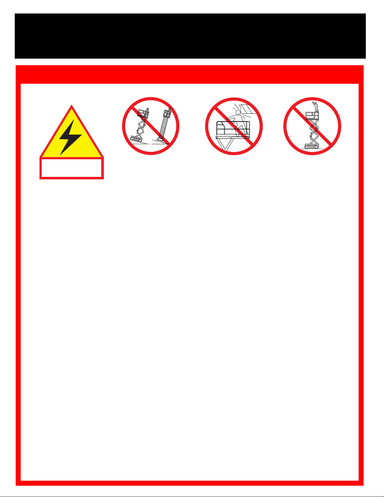
Safety Rules
Electrocution Hazard Tip Over Hazard Collision Hazard Fall Hazard
THIS MACHINE IS
NEVER
NOT INSULATED
USE OF THE AERIAL WORK PLATFORM
rial used for the job. It is designed for repair and assembly jobs and assignments at overhead workplaces (ceilings, cranes, roof
structures, buildings, etc.). All other uses of the aerial work platform
THIS AERIAL WORK PLATFORM IS NOT INSULATED!
electrical equipment!
Exceeding the specified permissible maximum load on the platform
X20N = 340 kg (750 lbs.) including 2 persons X20W = 453 kg (1000 lbs.) including 4 persons
X26N = 453 kg (1000 lbs.) including 3 persons X32N = 318 kg (700 lbs.) including 3 persons
The use and operation of the aerial work platform as a lifting tool or a crane (lifting of loads from below upwards or from up high on
is prohibited!
down)
NEVER
DISTRIBUTE
NEVER
debris; and avoiding them.
OPERATE
NEVER
IN CASE OF EMERGENCY
Climbing up the railing of the platform, standing on or stepping from the platform onto buildings, steel or prefab concrete structures,
etc.,
Dismantling the swing gate or other railing components
securely locked!
It is prohibited
To extend the height or the range by placing of ladders, scaffolds or similar devices on the platform
NEVER
INSPECT
wire connections and wheel bolts before using.
VERIFY
NEVER
IF ALARM SOUNDS
To bypass any safety equipment
range.
NEVER
Modifications to the aerial work platform
AFTER USE
exceed 400 N (90 lbs.) of side force.
all platform loads ev enly on the platform.
operate the machine without first surveying the work area for surface hazards such as holes, drop-offs, bumps, curbs, or
the machine only on surfaces capable of supporting wheel loads.
operate the machine when wind speeds exceed 45 km/h (28 mph) (12,5 m/sec.= Beaufort scale 6).
is prohibited!
to keep the swing gate in an open position (held open with tie-straps) when the platform is raised!
perform service on the machine while theplatform is elevated without blocking the elevating assembly.
the machine thoroughly for cracked welds, loose or missing hardware, hydraulic leaks, damaged cables or hoses, loose
that all labels are in place and legible before using.
use a machine that is damaged, not functioning properly, or has damaged or missing labels.
while the platform is elevated, STOP, carefully lower the platform. Move the machine to a firm, level surface.
charge batteries near sparks or open flame. Charging batteries emit explosive hydrogen gas.
, secure the work platform from unauthorized use by turning both keyswitches off and removing key.
platform elevated unless on
push EMERGENCY STOP button to deactivate all powered functions.
is prohibited
elevate the platform
or drive the machine with
firm, level surface.
: This aerial work platform is intended to lift persons and their tools as well as the mate-
For this reason it is imperative to keep a safe distance from live parts of
is prohibited!
and presents a danger for the persons on the aerial work platform and in its working
are prohibited
or permissible only at the approval of UpRight.
NEVER
are prohibited!
is prohibited!
position the platform
without first checking for
overhead obstructions or
other hazards.
Always make certain that the swing gate is closed and
NEVER
is prohibited!
climb, stand or
sit on platform
guardrails or midrail.
Page 3

I
NTRODUCTION
PRE-O
V
ISUAL INSPECTION
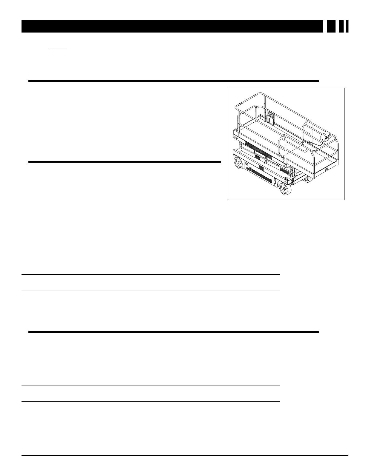
This manual covers operation of the X Series Self-Propelled Work Platforms.
the machine at all times.
This manual must be stored on
PERATION AND SAFETY INSPECTION
Carefully read, understand and follow all safety rules, operating instructions, labels, and the Scaffold Industry
Association’s MANUAL OF RESPONSIBILITIES. Perform the following steps each day before use.
1. Open module covers and inspect for damage, oil leaks, or missing parts.
2. Check the level of the hydraulic oil with the platform fully lowered. Open the Left Module and remo ve the reservoir cap. Oil should be visible in the filler screen. Add hydraulic fluid if necessary.
3. Check that fluid level in the batteries is correct. (See “Battery Maintenance” on page 14.)
4. Verify that batteries are charged.
5. Check that A.C. extension cord has been disconnected from charger.
6. Check that all guardrails are in place with all fa steners properly tightened.
7. Check that the slide-out deck extension is secured with the pin.
8. Inspect the machine thoroughly for cracked welds, loose or missing hardware, hydraulic leaks, damaged
control cable, loose wire connections and wheel bolts.
9. Close and secure module covers.
10. Move the machine, if necessary, to an unobstructed area to allow for full elevation.
C
HASSIS CONTROLS
11. Pull Chassis EMERGENCY STOP Switch to
the ON position.
12. Pull Platform EMERGENCY STOP Switch to
the ON position.
13. Turn and hold the Chassis Ke y Switch to
CHASSIS.
14. Push the Chassis Lift/Lower Switch to LIFT to
elevate the platform until the Scissor Brace
can be rotated to the vertical position. Block
the elevating assembly as described on
page 13.
15. Visually inspect the elevating assembly, lift cylinder, cables and hoses for cracked welds,
loose hardware, hydraulic leaks, loose wire
connections and erratic operation. Check for
missing or loose parts.
16. Verify that the depression mechanism has
deployed into position under each module.
Remove the Scissor Brace as described on page 13.
17. Push the Chassis Lift/Lower Switch to LIFT and fully elevate the platform.
18. Partially lower the platform by pushing the Chassis Lift/Lo w er Switch to LOWER, and check operation of the
audible lowering alarm.
Chassis Key
Switch
Figure 1:
Chassis Controls
Chassis
LIFT/LOWER
Switch
Chassis EMERGENCY
STOP Switch
3X-Series Work Platform
Page 4
E
Emergency Lowering Knob
Emergency Lowering Knob
MERGENCY LOWERING
19. Pull out on the Emergency Lowering Knob to
check for proper operation. Once the platform
has lowered, release the knob.
20. Push the Chassis EMERGENCY STOP Switch
to check for proper operation. All the machine
functions should be disabled. Pull out the
EMERGENCY STOP Switch to resume.
21. Turn the Chassis Key Switch to DECK.
22. Check that the route is clear of obstacles (persons, obstructions, holes, drop-offs, bumps,
and debris), is level, and capable of supporting
the wheel loads.
23. Mount the platform and properly close the
entrance.
P
LATFORM CONTROLS
24. Turn Lift/Drive Switch to DRIVE.
NOTE:
Use both HI and LOW drive (if applicable) when
performing the following step.
25. Engage the Interlock Switch and move the
Control Handle FORWARD, then REVERSE,
to check for speed control.
26. Push the Steering Switch RIGHT, then LEFT,
to check for steering control.
27. Turn the Lift/Drive Switch to LIFT.
28. Engage the Interlock Switch and move the
Control Handle forward to check platform lift
controls. Raise the platform to full elevation.
29. Pull back on the Control Handle. The platf orm
should descend and the audible lowering
alarm should sound.
30. Lower the platform completely.
31. Push the Platform EMERGENCY STOP
Switch to check for proper operation. All the
machine functions should be disabled. Pull
out the Platform EMERGENCY STOP Switch
to resume.
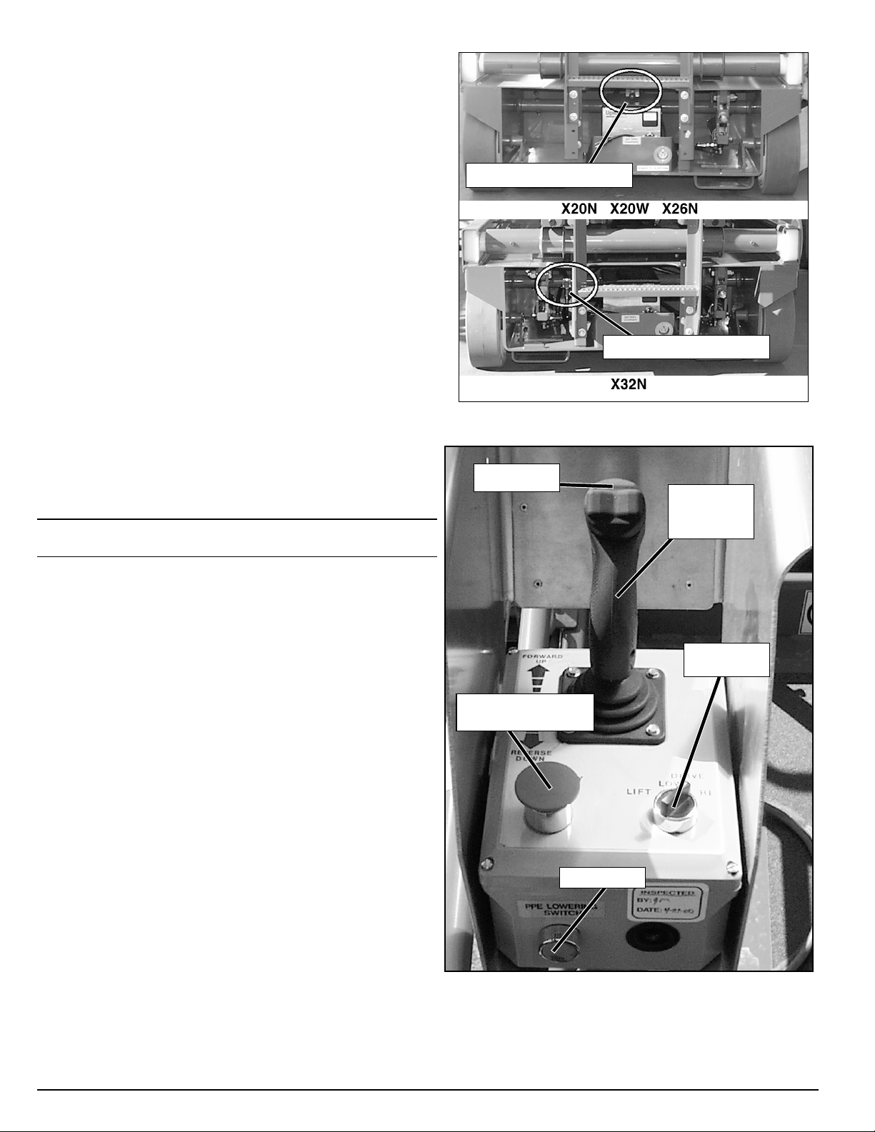
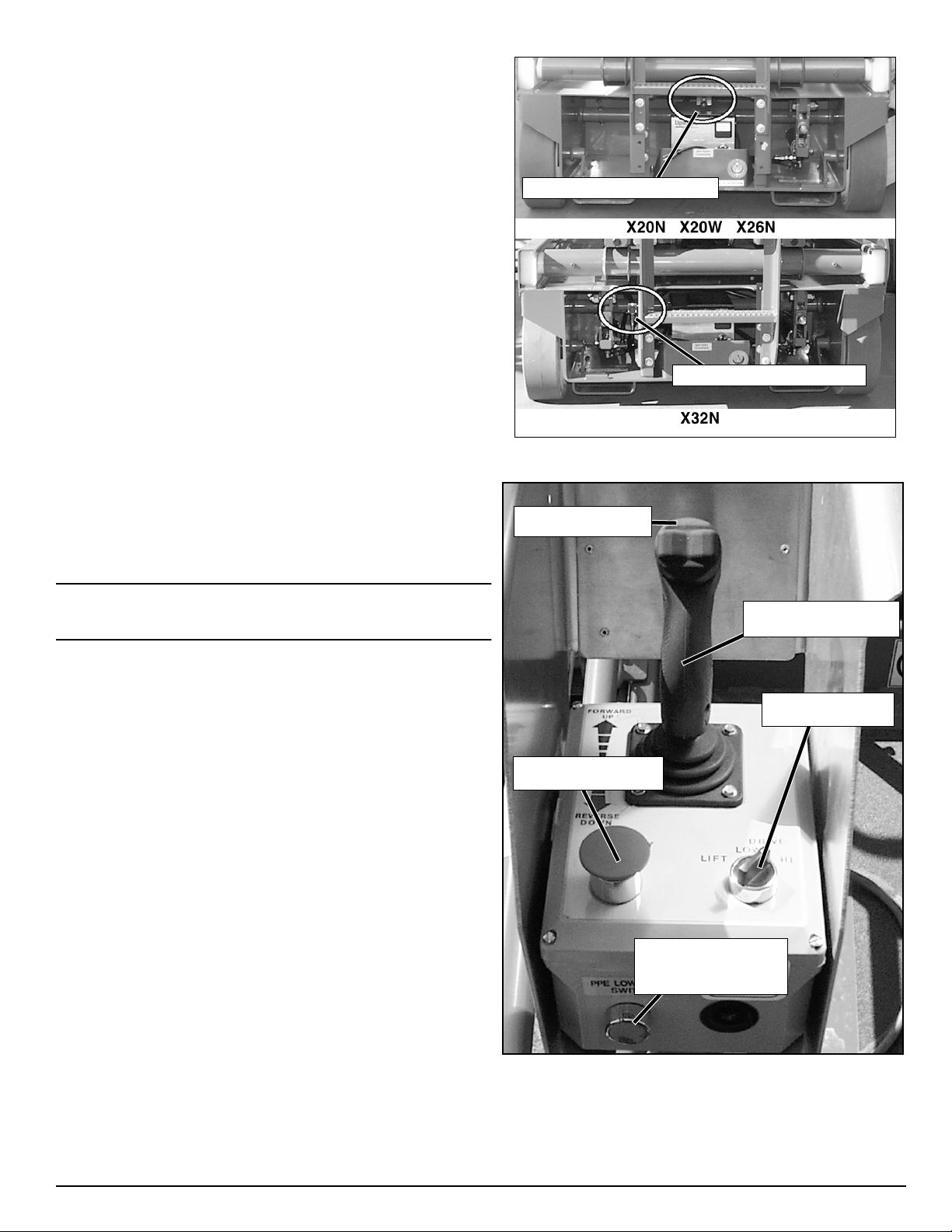
Figure 2:
Platform EMERGENCY
Emergency Lowering
Steering
Switch
STOP Switch
PPE Switch
Control
Handle with
Interlock
Switch
LIFT/ DRIVE
Switch
Figure 3:
Platform Controls
4 X-Series Work Platform
Page 5
O
Figure 4:
Platform Extension
PERATION
Before operating the work platform, ensure that the pre-operation safety inspection has been completed and that
any deficiencies have been corrected.
must be thoroughly trained on this machine, and must read, fully understand, and f ollo w this Oper ator Manual and
the Scaffold Industry Association’s Manual of Responsibilities of ANSI A92.6-1999.
LATFORM EXTENSION
P
1. Mount the platform and properly close the entrance.
2. Depress the foot lever located at the rear of the platform
extension. Push the platform extension forward until the
pin engages the front stop.
3. To retract the platform extension, depress the foot lever
and pull the platform extension toward the rear of the
machine until the pin engages the rear stop.
RAVEL WITH PLATFORM LOWERED
T
1. Check that the route is clear of obstacles (persons,
obstructions, holes, drop-offs, bumps , and debris), is lev el,
and capable of supporting the wheel loads.
2. Turn the Chassis Key Switch to DECK.
3. Pull the Chassis EMERGENCY STOP Switch to the ON
position.
4. Mount the platform and properly close the entrance.
5. Check clearances above, below, and to the sides of the platform.
6. Pull the Platform EMERGENCY STOP Switch to the ON position.
7. Turn the Lift/Drive Switch to DRIVE.
Never operate a damaged or malfunctioning machine.
The operator
NOTE:
S
NOTE:
Turn Lift/Drive Switch to HI (if applicable) for traveling on level ground, or to LOW
when extra torque is required for climbing grades.
8. Engage the Interlock Switch and move the Control Handle to FORWARD or REVERSE to travel in the
desired direction. The speed of the machine will vary depending on how far from center the Control Handle
is moved.
TEERING
1. Turn the Lift/Drive switch to DRIVE.
2. Engage the Interlock Switch, push the Steering Switch RIGHT or LEFT to turn the wheels in the desired
direction. Observe the tires while operating the machine to ensure proper direction.
Steering is not self-centering. Wheels must be returned to the straight ahead position
by operating the Steering Switch.
5X-Series Work Platform
Page 6

LEVATING THE PLATFORM
E
1. Select a firm, level surf ace.
2. Turn the Lift/Drive Switch to LIFT.
3. Engage the Interlock Switch and push the Control Handle forward.
4. If the machine is not level, the tilt alarm will sound and the machine will not lift or drive.
sounds, the platform must be lowered and the machine moved to a firm, level surface before
attempting to re-elevate the platform.
RAVEL WITH WORK PLATFORM ELEVATED
T
If the tilt alarm
NOTE:
The machine will travel at reduced speed when the platform is elevated.
1. Check that the route is clear of obstacles (persons, obstructions, holes, drop-offs, bumps, and debris), is
level, and capable of supporting the wheel loads.
2. Check clearances above, below, and to the sides of the platform.
3. Turn the Lift/Drive Switch to DRIVE.
4. Engage the Interlock Switch and move the Control Handle to FORWARD or REVERSE to travel in the
desired direction. The speed of the machine will vary depending on how far from center the Control Handle
is moved.
5. If the machine is not level, the tilt alarm will sound and the machine will not lift or drive.
sounds, the platform must be lowered and the machine moved to a firm, level surface before
attempting to re-elevate the platform.
OWERING THE PLATFORM
L
1. Turn the Lift/Drive Switch to LIFT.
2. Engage the Interlock Switch and pull back on the Control Handle to lower the platform.
3. The platform will stop when it reaches the PPE cut out height. To lower the platform fully, depress the green
PPE override button.
If the tilt alarm
6 X-Series Work Platform
Page 7
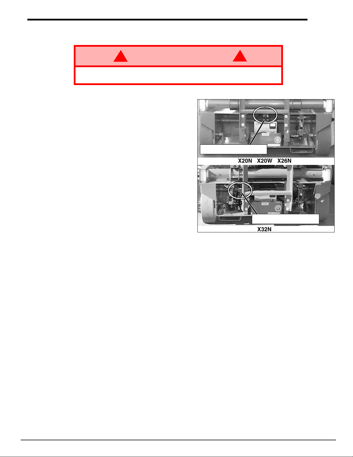
MERGENCY LOWERING
Emergency Lowering Knob
Emergency Lowering Knob
E
!
WARNING
If the platform should fail to lower,
assembly.
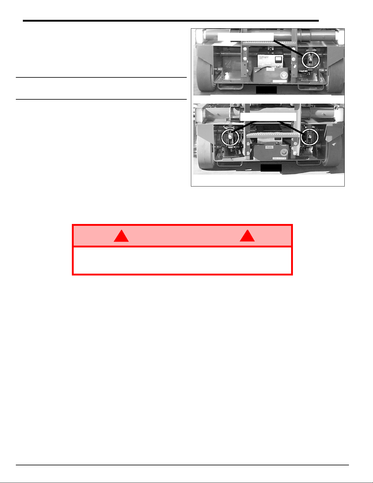
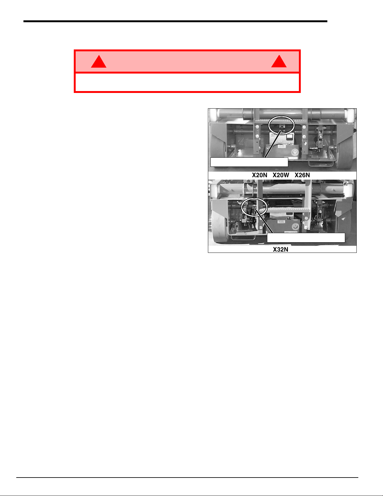
The Emergency Lowering Valve for the X20N, X20W,
and X26N is located at the rear of the machine, above
the charger.
The Emergency Lowering Valve for the X32N is located
at the rear of the machine, to the left of the charger.
1. Open the Emergency Lowering Valve by pulling
and holding the knob.
2. To close, release the knob. The platform will not
elevate if the Emergency Lowering Valve is open.
NEVER
!
climb down the elevating
Figure 5:
Emergency Lowering Valve Handle
7X-Series Work Platform
Page 8
OWER THE GUARDRAILS
L
This procedure applies only to the X26N model for the purpose of passing through a standard double doorway.
Guardrails must be returned to proper position before using the machine.
L
OWERING PROCEDURE
1. Ensure that the slide-out deck extension is fully retr acted and the dec k pin is loc k ed. Place the Platform Controls on the platform.
2. Remove and retain the set screws from the side guardrails and the slide-out deck guardrails.
3. Pull the four retaining pins and lower the slide-out deck guardrail completely.
4. Pull the two retaining pins and lower the rear guardrail until it rests on the stop screws.
5. Pull the two retaining pins and lower the side guardrails completely.
6. Raise the rear guardrail until the retaining pins engage. Remove and retain the stop screws and nuts from
the rear guardrail.
7. Pull the two retaining pins and lower the rear guardrail completely.
R
AISING PROCEDURE
1. Raise the rear guardrail until the retaining pins engage.
2. Install the stop screws and nuts on the rear guardrail and torque to 42 N-m (31 ft. lbs).
3. Pull the two retaining pins and lower the rear guardrail until it rests on the stop screws.
4. Pull the two retaining pins and raise the side guardrails until the tops are level with the rear guardrail.
5. Raise the rear guardrail until the retaining pins engage.
6. Pull the four retaining pins and raise the slide-out deck guardrail until the top is level with the side guardrails.
7. Hang the controller on the slide-out deck guardrail.
8. Install the set screws and torque to 42 N-m (31 ft. lbs).
, X26N
!
WARNING
Before operating machine, guardrails must be securely fastened in their
proper position.
!
8 X-Series Work Platform
Page 9
OLD DOWN GUARDRAILS
F
This procedure applies only to the X32N model for the purpose of passing through a standard double doorway.
Guardrails must be returned to proper position before using the machine.
F
OLD DOWN PROCEDURE
1. Unhook the controller from the side guardrail and place it on the platform.
2. Pull the retaining pin on the front guardrail and rotate inwards.
3. Pull the retaining pin on the rear guardrail and rotate inwards.
4. Starting with the slide-out deck guardrails and then the outer guardrails, lift up on each guardrail and fold
inward.
E
RECTION PROCEDURE
1. Starting with the outer guardrails and then the slide-out deck guardrails, raise each guardrail and drop it
down, securing it in the vertical position.
2. Rotate the front and rear upper guardrails outward and secure them to the opposite side guardrails, using
the retaining pins.
3. Hang the controller on the side guardrail.
, X32N
Before operating the machine, guardrails must be securely fastened in their
proper position.
FTER USE EACH DAY
A
1. Ensure that the platform is fully lowered.
2. Park the machine on a firm, level surface, preferably under cover, secure against vandals, children, and
unauthorized operation.
3. Turn the Key Switch to OFF and remove the key to prevent unauthorized operation.
Electrocution Hazard
!
WARNING
This machine is not insulated. Follow your national safety standards and maintain the
required safety distance when working near energized equipment.
!
THIS MACHINE IS
NOT INSULATED
9X-Series Work Platform
Page 10
ARKING BRAKE RELEASE
P
Perform the following only when the machine will
not operate under its own power and it is necessary
to move the machine or when winching onto a
trailer to transport.
Parking Brake Release
NOTE:
X32N models have two identical brake adjustment
nuts located on both sides of the ladder . The X20N,
X20W, and X26N have only one.
The Brake Adjustment/Release Nut(s) is/are
located at the rear of the machine to the right and/or
left of the ladder.
1. To release the brakes turn the nut(s) counterclockwise until the brakes disengage the tires.
2. The machine will now roll when pushed or
pulled.
3. To re-engage the brakes , turn the nut(s) clockwise until the brakes have fully engaged the
tires. V erify that the brak es hav e fully engaged
the rear tires before operating the machine b y
testing their ability to hold the machine on a
22% grade (X32N 20 %).
!
WARNING
Never tow faster than 0,3 m/sec. (1 ft./sec.)
Never operate the work platform with the parking brakes released. Serious
injury or damage could result.
Figure 6:
REAR
X20N X20W X26N
Parking Brake Release
REAR
X32N
Parking Brake Release
!
10 X-Series Work Platform
Page 11
T
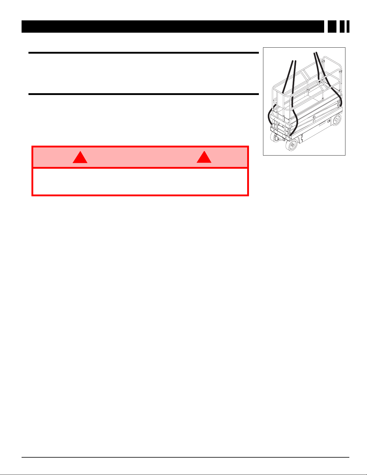
Figure 7:
Secure Crane
Straps
RANSPORTING THE WORK PLATFORM
BY C
BY F
RANE
Secure straps to lugs only. Guide the crane straps inside the rails and outside
the chassis.
ORKLIFT
Forklift from the rear of the machine using the forklift pock ets pro vided. If necessary, the machine may be forklifted from the side by lifting under the Chassis
Modules.
!
WARNING
Forklifting is for tr ansporting only.
See specifications for weight of the work platf orm and be certain that forklift is
of adequate capacity to lift the platform.
!
11X-Series Work Platform
Page 12
BY T
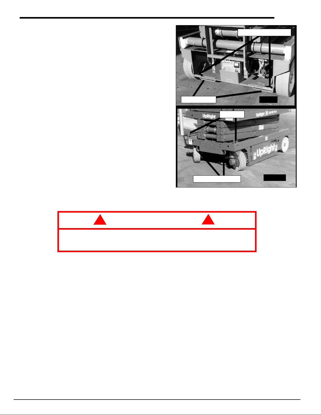
Rear Tie Down/Lift Lugs
Front Tie Down Lugs
Lift Lugs
REAR
Forklift Pockets
FRONT
Figure 8:
Transporting the Work Platform
RUCK
1. Maneuver the work platform into transport position
and chock the wheels. The platf o rm must be in the
fully lowered position for transport.
2. Secure the work platform to the transport vehicle
by attaching chains or straps of adequate load
capacity to the front and rear tie downs.
!
CAUTION
Front tie down lugs are not to be used to lift work platform.
Overtightening of chains or straps attached to tie down lugs may result in
damage to the work platform.
!
12 X-Series Work Platform
Page 13
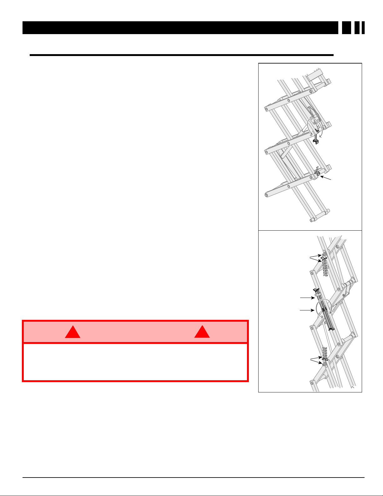
M
BRACE RESTS ON
WELDMENT WHEN IN
BLOCKING POSITION
ROTA TE BRACE
CLOCKWISE
TO BLOCK
PIN RESTS ON
BRACE WHEN IN
BLOCKING POSITION
SCISSOR BRACE
IN REST POSITION
BRACE ROTA TES
TO BLOCKING
POSITION
BRACE RESTS ON
PIN WHEN IN
BLOCKING POSITION
X20N, X20W, and X26N
X32N
Figure 9:
Blocking the Elevating
Assembly
AINTENANCE
LOCKING ELEVATING ASSEMBLY
B
I
NSTALLATION
1. Park the work platform on a firm, level surface.
2. Pull Chassis EMERGENCY STOP Switch to the ON position.
3. Pull Platform EMERGENCY STOP Switch to the ON position.
4. Turn and hold the Chassis Key Switch to CHASSIS.
5. Push the Chassis Lift/Lower Switch to LIFT to elev ate the platf orm
until the Scissor Brace can be rotated to the vertical position.
6. X20N, X20W, and X26N – From the rear of the machine, lift the
Scissor Brace from its stowed position. Rotate upward and outward, then down until it is hanging vertically below its attachment
point.
7. X32N – From the left side of the machine, pull the locking pin
securing the brace. Rotate the Scissor Brace counterclockwise
until it is in the vertical position.
8. Lower the platform by pushing the Chassis Lift/Lower Switch to
LOWER and gradually lower the platform until the Scissor Brace
is supporting the platform.
R
EMOVAL
1. Using the Chassis Controls, gradually elevate the platform until
the Scissor Brace is clear.
2. X20N, X20W, and X26N – Rotate the Scissor Brace outward and
upward over its mounting point until it rests in the stowed position.
3. X32N – Rotate the Scissor Brace clockwise until the locking pin
engages.
4. Lower the platform by pushing the Chassis Lift/Lower Switch to
LOWER to completely lower the platform.
!
WARNING
Never perform service while the platform is elev ated without first blocking the
elevating assembly.
DO NOT
DO NOT
stand in elevating assembly area while deploying or storing brace.
block elevating assembly with a load on the platform.
!
13X-Series Work Platform
Page 14
ATTERY MAINTENANCE
B
!
WARNING
Hazard of explosive gas mixture. Keep sparks, flame, and smoking material
away from batteries.
Always wear safety glasses when working near batteries.
Battery fluid is highly corrosive. Thoroughly rinse away any spilled fluid with
clean water.
Always replace batteries with UpRight batteries or manufacturer approved
replacements weighing 28 kg. (62 lbs.) each.
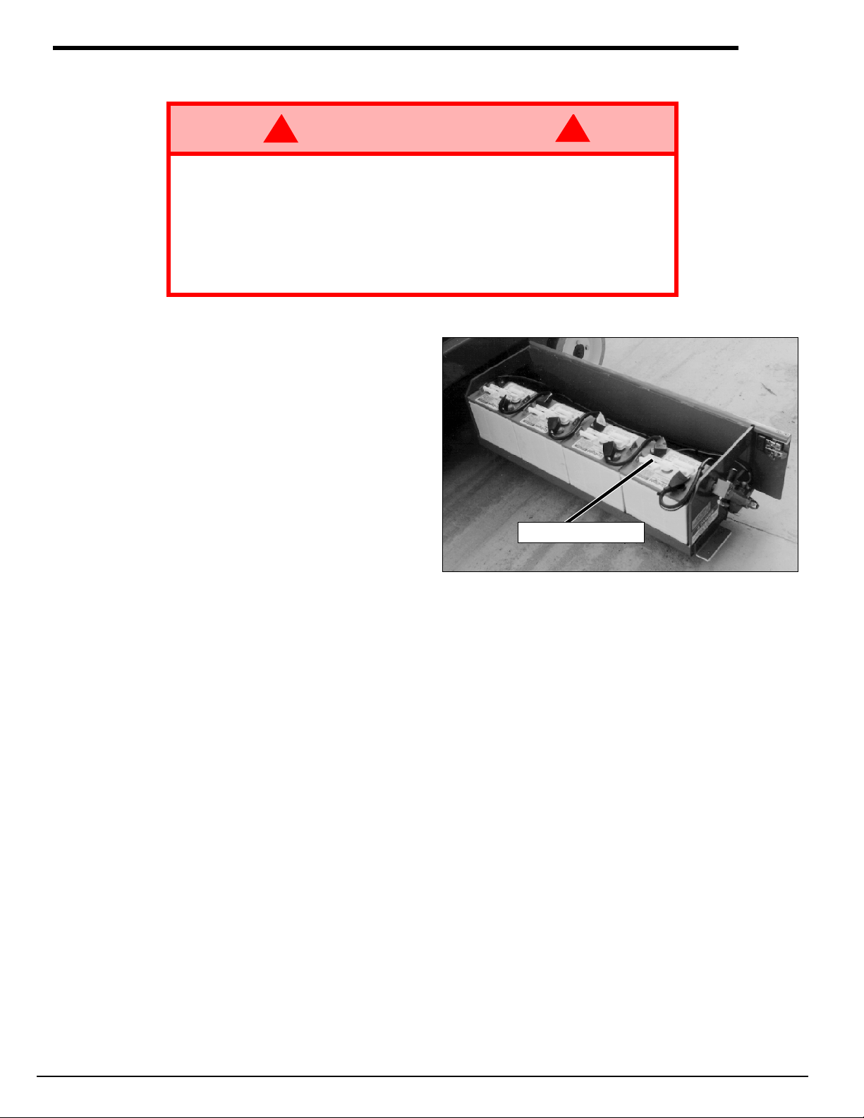
• Check the battery fluid level daily, especially if the work platform is being used in
a warm, dry climate.
• If the electrolyte level is lo w er than 10 mm
(3/8 in.) above the plates, add distilled
water ONLY. DO NOT use tap water with
high mineral content, as it will shorten battery life.
• The battery and cables should be
inspected regularly for signs of cracks in
the case, electrolyte leakage and corrosion of the terminals. Inspect cables for
worn spots or breaks in the insulation and
for broken cab le terminals. K eep terminals
and tops of batteries clean.
• Refer to the Service Manual to extend battery life and for complete service instructions.
Figure 10:
!
Remove to check fluid
Power Module
14 X-Series Work Platform
Page 15

ATTERY CHARGING
B
Charge the batteries at the end of each work shift or
sooner if batteries have been discharged.
1. Check battery fluid level. If electrolyte level is
lower than 10 mm (3/8 in.) above the plates,
add distilled water only.
2. Connect an extension cord to the battery
charger plug. Plug the extension cord
(1.5 mm² [12 gauge] minimum conductor
diameter; 15 m [50 ft.] maximum length) to
properly grounded outlet of correct voltage and
frequency.
3. The battery charger turns on automatically
after a short delay.
Figure 11:
Charger Plug
Charger
(behind plate)
REAR
Battery Charger
NOTE:
The battery charger circuit must be used with a GFI (Ground Fault Circuit Interrupt)
outlet.
DO NOT operate the machine while charger is plugged in.
!
WARNING
Charge batteries only in a well-ventilated area.
Do not charge the batteries if the work platform is near a source of sparks or
flames.
Permanent damage to the batteries will result if the batteries are not
recharged immediately after discharging.
Never leave the battery charger operating for more than two days.
Never disconnect the cables from the batteries when the battery charger is
operating.
Keep the battery charger dry.
!
15X-Series Work Platform
Page 16
P
REVENTATIVE MAINTENANCE
The complete inspection consists of periodic visual and operational checks, along with periodic minor adjustments
that assure proper performance. Daily inspection will prevent abnormal wear and will prolong the life of all systems. The inspection and maintenance schedule is to be performed at regular intervals. Inspection and maintenance shall be performed by personnel who are trained and familiar with mechanical and electrical procedures.
!
WARNING
Before performing preventative maintenance, familiarize yourself with the
operation of the machine.
Always block the elevating assemb ly whenever it is necessary to perform
maintenance while the platform is elevated.
The preventative maintenance table has been designed for machine service and maintenance repair. Please photocopy the following page and use the table as a checklist when inspecting the machine for service.
!
16 X-Series Work Platform
Page 17
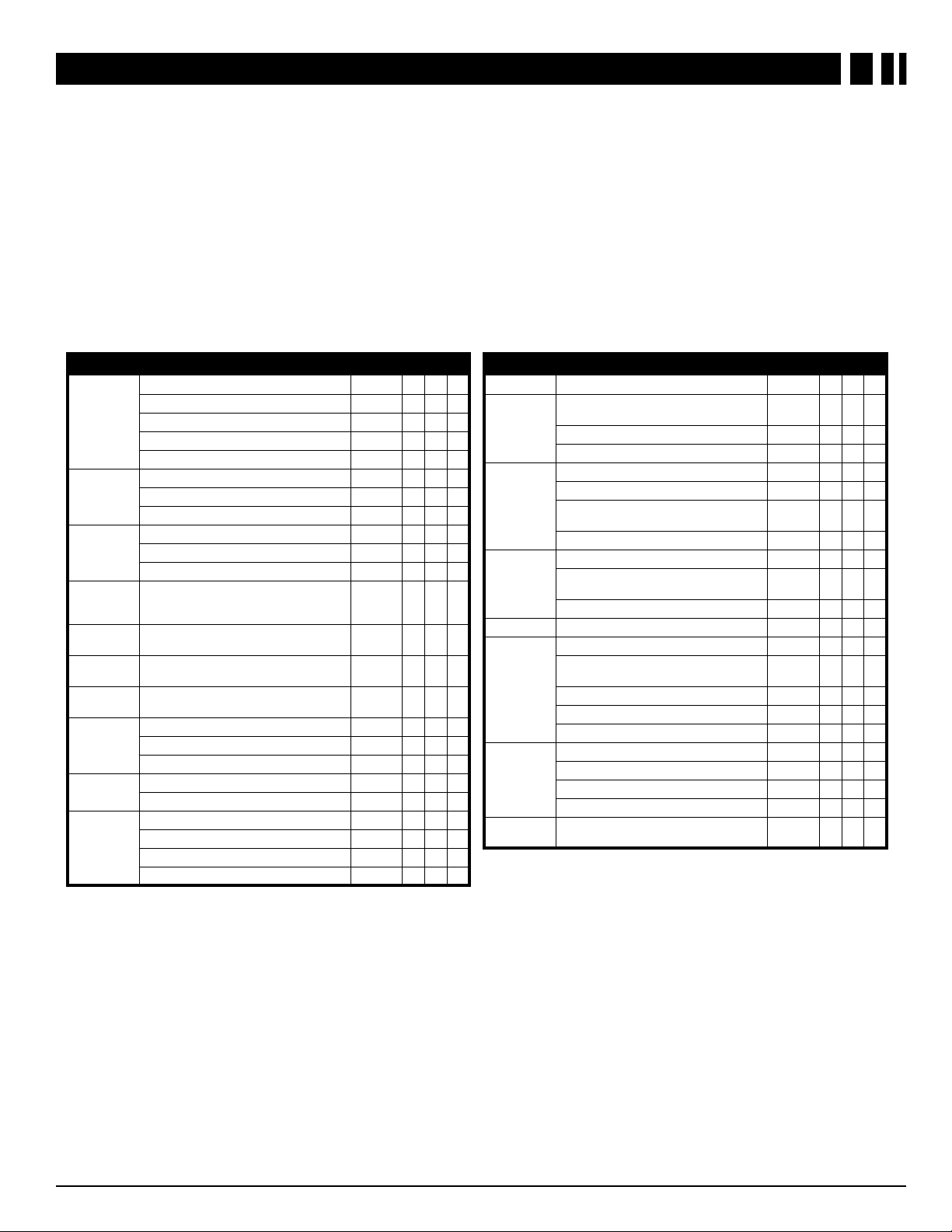
P
REVENTATIVE MAINTENANCE CHECKLIST
REVENTATIVE MAINTENANCE KEY
P
I
NTERVAL
Daily = each shift or every day
50h/30d = every 50 hours or 30 days
250h/6m = every 250 hours or 6 months
1000h/2y = every 1000 hours or 2 years
Y = Yes/Acceptable
N = No/Not Acceptable
R = Repaired/Acceptable
P
REVENTATIVE MAINTENANCE REPORT
Date:____________________________________
Owner: __________________________________
Model No:________________________________
Serial No: ________________________________
Serviced By: ______________________________
Service Interval: ___________________________
COMPONENT INSPECTION OR SERVICES INTERVAL Y N R
Check electrolyte level Daily
Check specific gravity 6m
Batteries
Hydraulic Oil
Hydraulic
System
Emergency
Hydraulic
System
Chassis
Controls
Platform
Controls
Control
Cable
Platform
Deck and
Rails
Tires
Hydraulic
Pump
Clean exterior 6m
Check battery cable condition Daily
Clean terminals 6m
Check oil level Daily
Change filter 6m
Drain and replace oil 2y
Check for leaks Daily
Check hose connections 30d
Check hoses for exterior wear 30d
Operate the emergency lowering valve and
check for serviceability
Check switch operation Daily
Check switch operation Daily
Check the exterior of the cable for
pinching, binding or wear
Check fasteners for proper torque Daily
Check welds for cracks Daily
Check condition of deck Daily
Check for damage Daily
Check lug nuts (torque to 90 ft. lbs.) 6m
Wipe clean 30d
Check for leaks at mating surfaces 30d
Check for hose fitting leaks Daily
Check mounting bolts for proper torque 6m
Daily
6m
COMPONENT INSPECTION OR SERVICES INTERVAL Y N R
Drive Motors
Steering
System
Elevating
Assembly
Chassis
Tilt Sensor
Lift Cylinder
Entire Unit
Labels
Check for operation Daily
Check hardware & fittings for proper
torque
Grease pivot pins 30d
Check steering cylinder for leaks 30d
Inspect for structural cracks Daily
Check pivot points for wear 6m
Check mounting pin pivot bolts for proper
torque
Check elevating arms for bending 6m
Check hoses for pinch or rubbing points Daily
Check component mounting for proper
torque
Check welds for cracks Daily
Check for operation 6m
Check the cylinder rod for wear 30d
Check mounting pin pivot bolts for proper
torque
Check seals for leaks 30d
Inspect pivot points for wear 6m
Check fittings for proper torque 6m
Check for and repair collision damage Daily
Check fasteners for proper torque 6m
Check for corrosion-remove and repaint 6m
Lubricate 30d
Check for peeling, missing, or unreadable
labels & replace
6m
6m
6m
6m
Daily
17X-Series Work Platform
Page 18

S
PECIFICATIONS
ITEM X20N X20W X26N X32N
Platform Size w/ Extension
Max. Platform Capacity
Standard 340 kg [750 lbs.] 455 kg [1000 lbs.] 455 kg [1000 lbs.] 317 kg [700 lbs.]
on Extension 110 kg [250 lbs.] 110 kg [250 lbs.] 110 kg [250 lbs.] 110 kg [250 lbs.]
Max. No. of occupants
Standard (total) 3 people 4 people 4 people 3 people
on Extension 1 person 1 person 1 person 1 person
Height
Working Height 8.1 m [26 ft.] 8.1 m [26 ft.] 9.93 m [32 ft.] 11.6 m [38 ft.]
Max. Platform Height 6.1 m [20 ft.] 6.1 m [20 ft.] 7.93 m [26 ft.] 9.75 m [32 ft.]
Min. Platform Height 0.96 m [38 in.] 0.96 m [38 in.] 1.09 m [43 in.] 1.22 m [48 in.]
Dimensions
Weight 1736 kg [3828 lbs.] 1938 kg [4273 lbs.] 2153 kg [4747 lbs.] 2486 kg [5481 lbs.]
Overall Width 0.82 m [32.5 in.] 1.22 m [48 in.] 1.22 m [48 in.] 1.22 m [48 in.]
Overall Height 2.06 m [78.5 in.] 2.06 m [78.5 in.] 2.19 m [83.5 in.] 2.32 m [88.5 in.]
Overall Height, Rails Lowered N/A N/A 1.98 m [78 in.] 1.88 m [74 in.]
Overall Length, Extension In 2.35 m [92.5 in.] 2.35 m [92.5 in.] 2.35 m [92.5 in.] 2.35 m [92.5 in.]
Overall Length, Extension Out 3.26 m [128.5 in.] 3.26 m [128.5 in.] 3.26 m [128.5 in.] 3.26 m [128.5 in.]
Drivable Height
Drive Speed
Platform Lowered 0 to 3,2 km/h [0 to 2.0 mph]
Platform Raised 0 to 1 km/h [0 to 0.62 mph]
Energy Source
Motor
System Voltage
Battery Charger
Battery Duty Cycle
Hydraulic Tank Capacity
Maximum Hydraulic Pressure
Lift System
Lift Speed
Control System
Drive System
Tires
Parking Brake
Turning Radius
Maximum Gradeability
Wheel Base
Guardrails
Toeboard
0.71 m x 2.21 m
[28 in. x 87 in.]
6.1 m [20 ft.] 6.1 m [20 ft.] 7.93 m [26 ft.] 9.75 m [32 ft.]
24 Volt Battery Pack (4-220 A Hour, 6 Volt Batteries, min. wt. 28.12 kg [62 lbs.] each)
15 L [4 US Gallons] 15 L [4 US Gallons] 15 L [4 US Gallons] 19 L [5 US Gallons]
One Single Stage
Lift Cylinder
Raise, 35 sec./Lower 30 sec. Raise, 40 sec./Lower 30 sec. Raise, 45 sec./Lower 40 sec. Raise, 65 sec./Lower 40 sec.
Proportional Control Handle with Interlock Switch, Rotary Drive/Lift Switch,
12° [22%] 12° [22%] 12° [22%] 11° [20%]
1.12 m x 2.21 m
[44 in. x 87 in.]
24 Volt 4 Horse Power DC Electric Motor
24 Volt DC
25 A, 110/220 V AC
25% for 8 Hours
207 bar [3000 psi]
One Single Stage
Lift Cylinder
and Red Mushroom EMERGENCY STOP Switch
Dual Front Wheel Hydraulic Motors
381 mm [15 in.] Diameter Solid Rubber, non-marking
Dual Spring Applied, Hydraulic Release
203 mm [8 in.] Inside
1.9 m [74.75 in.]
1.02 m [40 in.] High
152 mm [6 in.] High
1.17 m x 2.21 m
[44.25 in. x 87 in.]
One Single Stage
Lift Cylinder
1.17 m x 2.21 m
[44 in. x 87 in.]
Two Single Stage
Lift Cylinders
Specifications are subject to change without notice. Hot weather or heavy use may reduce performance.
Meets or exceeds all applicable CE and GS Machinery Directive Requirements.
18 X-Series Work Platform
Page 19
Section française
Consignes de sécurité
Risque d’électrocution Risque de basculement Risque de collision Risque de chute
CETTE MACHINE
N’EST PAS ISOLÉE.
NE JAMAIS
forme ou conduire la
machine avec la plate-f orme
élevée si elle n’est pas sur
élever la plate-
NE JAMAIS
élever la plate-
forme avant de s’être assuré
de l’absence d’obstacles en
hauteur ou autres dangers.
NE JAMAIS
monter, ni
se tenir debout ou assis
sur les rampes du
garde-corps.
une surface plane et ferme.
USAGE DE LA PLATE-FORME ÉLÉVATRICE :
outillage et des matériaux utilisés sur le chantier. Elle est conçue pour les travaux de réparations et d’assemblage sur les points
élevés (plafonds, grues, charpentes de toit, immeubles, etc.). Tout autre usage de la plate-forme élévatrice
CETTE PLATE-FORME ÉLÉVATRICE N’EST PAS ISOLÉE !
équipements électriques sous tension !
Il est interdit
Il est interdit
NE JAMAIS
RÉPARTIR
NE JAMAIS
dénivellations, bosses, trottoirs ou débris, et les éviter.
N’UTILISER
NE JAMAIS
EN CAS D’URGENCE,
Il est interdit
structure préfabriquée etc. !
Il est interdit
et verrouillé !
Il est interdit
Il est interdit
similaires !
NE JAMAIS
dispositif d’élévation.
INSPECTER
de fuites hydrauliques, de câbles et flexibles endommagés, de branchements électriques et boulons de roues desserrés, avant
de l’utiliser.
VÉRIFIER
NE JAMAIS
quants ou endommagés.
SI L’ALARME RETENTIT
machine jusqu’à une surface plane et ferme.
Il est interdit
celles se trouvant dans la zone de travail.
NE JAMAIS
l’hydrogène, un gaz explosif.
Sauf autorisation de la part d’UpRight, toute modification de la plate-forme
APRÈS AVOIR UTILISÉ
d’empêcher l’utilisation non autorisée de la plate-forme.
de dépasser la charge maximum admissible !
X20N = 340 kg (750 lb) deux personnes incluses X20W = 453 kg (1000 lb) quatre personnes incluses
X26N = 453 kg (1000 lb) trois personnes incluses X32N = 318 kg (700 lb) trois personnes incluses
d’utiliser la plate-forme comme appareil de levage ou grue (levage des charges par le dessous ou le dessus) !
dépasser 400 N (90 lb) de force latérale.
uniformément toutes les charges placées sur la plate-forme.
utiliser la machine sans avoir d’abord vérifié si la zone de travail est exempte de dangers tels que des trous,
la machine que sur des surfaces pouvant supporter la charge des roues.
utiliser la machine lorsque le vent souffle à plus de 45 km/h (28 mi/h) [12,5 m/sec. = 6 sur l’échelle de Beaufort].
appuyer sur le bouton d’arrêt d’urgence (EMERGENCY STOP) pour désactiver toutes les fonctions.
de monter ou de se tenir sur les garde-corps de la plate-forme et de passer de la plate-forme à un immeuble, une
de retirer le portillon pivotant, ou toute autre pièce de garde-corps ! Toujours vérifier que le portillon est fermé
de maintenir le portillon en position ouverte (par exemple au moyen d’attaches) lorsque la plate-forme est élevée !
d’accroître la hauteur ou la portée de la plate-forme au moyen d’échelles, échafaudages ou autres dispositifs
effectuer de travaux d’entretien sur la machine, si la plate-forme est en position élevée, sans tout d’abord bloquer le
minutieusement la machine en vue de soudures fissurées, de pièces de boulonnerie manquantes ou desserrées,
que tous les autocollants sont en place et lisibles avant d’utiliser la machine.
utiliser une machine qui est endommagée, qui ne fonctionne pas correctement ou dont les autocollants sont man-
lorsque la plate-forme est élevée, ARRÊTER, abaisser la plate-forme avec précaution. Conduire la
de mettre tout dispositif de sécurité hors service, ce qui mettrait en danger les personnes à bord de la plate-forme et
charger les batteries à proximité d’étincelles ou d’une flamme vive. Lors de la charge, les batteries dégagent de
la plate-forme élévatrice, mettre les deux contacteurs à clé en position d’arrêt (off), puis retirer la clé afin
Cette plate-forme élévatrice est destinée au levage de toute personne, de son
est interdit !
C’est pourquoi il est impératif de rester à distance sûre des lignes et
est interdite
.
Page 20

I
NTRODUCTION
Ce manuel s’applique à l’utilisation des plates-formes élévatrices autopropulsées série X.
la machine en tout temps.
V
ÉRIFICATIONS PRÉLIMINAIRES ET DE SÉCURITÉ
Lire attentivement et veiller à bien comprendre et à respecter toutes les règles de sécurité, instructions d’utilisation, et autocollants, ainsi que le MANUEL DES RESPONSABILITÉS de la Scaffold Industry Association. Chaque
jour avant d’utiliser la machine :
I
NSPECTION VISUELLE
1. Ouvrir les panneaux des modules et s’assurer de l’absence de dommages, fuites d’huile ou pièces
manquantes.
2. Vérifier le niveau de l’huile hydraulique une fois la plate-forme entièrement abaissée. Ouvrir le module de
gauche et retirer le bouchon du réservoir. L’huile doit être visible dans le tamis de la goulotte de remplissage.
Faire l’appoint si nécessaire.
3. Vérifier que le niveau de liquide de la batterie est correct (voir Entretien des batteries à la page 31).
4. Vérifier que les batteries sont chargées.
5. Vérifier que le prolongateur d’alimentation CA a été débranché du chargeur.
6. Vérifier que tous les garde-corps sont en place et que tous les éléments de fixation sont bien serrés.
7. Vérifier que l’extension rétractable de la plate-forme est bloquée avec l’axe.
8. Inspecter minutieusement la machine en vue de soudures fissurées, de pièces de boulonnerie manquantes
ou desserrées, de fuites hydrauliques, de câbles et flexibles endommagés, de branchements électriques et
boulons de roues desserrés,avant de l’utiliser.
9. Fermer et verrouiller les couvercles des modules.
10. Au besoin, déplacer la machine jusqu’à un endroit dégagé afin de pouvoir l’élever complètement.
Veiller à le garder sur
C
OMMANDES DU CHÂSSIS
11. Tirer le bouton d’arrêt d’urgence (EMERGENCY STOP) du châssis en position activée
(ON).
12. Tirer le bouton d’arrêt d’urgence (EMERGENCY STOP) de la plate-forme en position
activée (ON).
13. Tourner et maintenir le contacteur à clé du
châssis en position châssis (CHASSIS).
14. Pousser la commande de relevage/abaissement du châssis en position de relevage
(LIFT) pour élever la plate-f orme suffisamment
pour mettre la barre de verrouillage à la verticale. Bloquer le dispositif d’élévation comme
décrit à la page 30.
15. Inspecter le mécanisme élévateur, le vérin de
relevage, les câbles et les flexibles, en vue de
soudures fissurées, pièces desserrées, fuites
hydrauliques, branchements desserrés et
fonctionnement irrégulier. Vérifier qu’aucune pièce n’est lâche ou manquante.
16. Vérifier que les supports du mécanisme à dépression se sont déployés en position au-dessous de chaque
module. Retirer le blocage de ciseau comme décrit à la page 30.
17. Mettre le commutateur de relevage/abaissement du châssis en position de relevage (LIFT) et élever la
plate-forme au maximum.
18. Abaisser partiellement la plate-forme en mettant le commutateur de relevage/abaissement du châssis en
position d’abaissement (LOWER) et vérifier le fonctionnement de l’alarme sonore.
Contacteur à
clé du châssis
Figure 1 :
Commutateur de relevage/
abaissement du châssis
Commandes du châssis
Bouton d’arrêt
d’urgence du châssis
20 Plate-forme élévatrice de travail série X
Page 21
A
Bouton d’abaissement d’urgence
Bouton d’abaissement d’urgence
BAISSEMENT D’URGENCE
19. Tirer le bouton d’abaissement d’urgence pour
vérifier qu’il fonctionne correctement. Une fois
la plate-forme abaissée, relâcher le bouton.
20. Appuyer sur le bouton d’arrêt d’urgence
(EMERGENCY STOP) du châssis pour en vérifier le bon fonctionnement. Toutes les fonctions
de la machine doivent être désactivées. Tirer le
bouton d’arrêt d’urgence (EMERGENCY
STOP) pour remettre la machine en service.
21. Mettre le contacteur à clé du châssis en position plate-forme (DECK).
22. Vérifier que le parcours est exempt de tout obstacle (personnes, objets, trous, dénivellations,
bosses et débris), que le terrain est plat et peut
supporter la charge des roues.
23. Monter sur la plate-forme et fermer correctement l’entrée.
C
OMMANDES DE LA PLATE-FORME
24. Tourner le sélecteur de levage/conduite sur la
position conduite (DRIVE).
NOTA :
Si la machine est équipée d’un sélecteur de
gammes haute et basse (HI/LOW), l’utiliser pour
l’étape suivante.
25. Engager le bouton de sûreté et actionner le
levier EN AVANT et EN ARRIÈRE pour vérifier le contrôle de la vitesse.
26. Pousser le bouton de commande de direction
à DROITE puis à GAUCHE pour vérifier la
commande de la direction.
27. Tourner le sélecteur de conduite/levage sur
levage (LIFT).
28. Engager le bouton de sûreté et pousser le
levier de commande vers l’avant pour vérifier
le fonctionnement des commandes de relevage de la plate-forme. Élever la plate-forme
au maximum.
29. Tirer le levier de commande vers l’arrière. La
plate-forme doit descendre et une alarme
sonore d’abaissement doit retentir.
30. Abaisser complètement la plate-forme.
31. Appuyer sur le bouton d’arrêt d’urgence
(EMERGENCY STOP) de la plate-f orme pour
en vérifier le bon fonctionnement. Toutes les
fonctions de la machine doivent être désactivées. Tirer le bouton d’arrêt d’urgence
(EMERGENCY STOP) pour remettre la machine en service.
Figure 2 :
Bouton de commande
Bouton d’arrêt d’urgence
de la plate-forme
Figure 3 :
Abaissement d’urgence
de direction
Commandes de la plate-forme
Levier de commande av ec
commutateur de sûreté
Commutateur
d’annulation de
protection personnelle
(PPE)
Sélecteur de
LEVAGE/CONDUITE
21Plate-forme élévatrice de travail série X
Page 22

U
Figure 4 :
Extension de la plate-forme
TILISATION
Avant d’utiliser la plate-forme élévatrice, s’assurer que les inspections de sécurité avant utilisation ont été effectuées et que tous les problèmes éventuels ont été corrigés.
qui ne fonctionne pas correctement.
bien comprendre et respecter ce guide de l’opérateur, ainsi que le manuel des responsabilités de la Scaffold
Industry Association ANSI A92.6-1999.
XTENSION DE PLATE-FORME
E
1. Monter sur la plate-forme et fermer correctement l’entrée.
2. Appuyer sur le levier au pied de l’arrière de l’extension de
plate-forme. Pousser l’extension de plate-forme en avant
jusqu’à ce que l’axe de sûreté s’engage dans la butée
avant.
3. Pour rétracter l’extension, appuyer sur la pédale et tirer
l’extension vers l’arrière de la machine jusqu’à ce que
l’axe s’engage dans la butée arrière.
ÉPLACEMENT AVEC LA PLATE-FORME ABAISSÉE
D
1. Vérifier que le parcours est exempt de tout obstacle (personnes, objets, trous, dénivellations, bosses et débris),
que le terrain est plat et peut supporter la charge des
roues.
2. Mettre le contacteur à clé du châssis en position plate-forme (DECK).
3. Tirer le bouton d’arrêt d’urgence (EMERGENCY STOP) du châssis en position activée (ON).
4. Monter sur la plate-forme et fermer correctement l’entrée.
5. Vérifier les dégagements au-dessus, au-dessous et sur les côtés de la plate-forme.
6. Tirer le bouton d’arrêt d’urgence (EMERGENCY STOP) de la plate-forme en position activée (ON).
7. Tourner le sélecteur de conduite/levage sur la position conduite (DRIVE).
L’opérateur doit être dûment formé sur cette machine et doit lire et veiller à
Ne jamais utiliser une machine endommagée ou
NOTA :
NOTA :
22 Plate-forme élévatrice de travail série X
Si la machine en est équipée, mettre le sélecteur de gamme sur gamme haute (HI)
pour la conduite sur sol horizontal ou sur gamme basse (LOW) si un couple plus
élevé est nécessaire pour gravir une pente.
8. Engager le bouton de sûreté et mettre le levier de commande en position de marche avant (FORWARD) ou
de marche arrière (REVERSE) selon le sens de marche désiré. La vitesse de la machine varie en fonction
de l’éloignement du levier de sa position centrale.
IRECTION
D
1. Tourner le sélecteur de levage/conduite sur la position conduite (DRIVE).
2. Engager le bouton de sûreté, pousser le commutateur de direction vers la GAUCHE ou la DROITE pour
orienter les roues dans le sens voulu. Pendant la manœuvre de la machine observer les roues pour
s’assurer qu’elles sont braquées dans la direction voulue.
La direction n’est pas à centrage automatique. Les roues doivent être remises en
position droite à l’aide du bouton de commande de direction.
Page 23

LÉVATION DE LA PLATE-FORME
É
1. Choisir une surface plane et ferme.
2. Tourner le sélecteur de conduite/levage sur levage (LIFT).
3. Engager le bouton de sûreté et pousser le levier de commande vers l’avant.
4. Si la machine n’est pas de niveau, l’alarme d’inclinaison retentit et la plate-forme ne peut être ni élevée, ni
conduite.
jusqu’à une surface plane avant d’être de nouveau levée.
ÉPLACEMENT AVEC LA PLATE-FORME ÉLEVÉE
D
Si l’alarme d’inclinaison retentit, la plate-forme doit être abaissée et la machine conduite
NOTA :
La machine se déplace à vitesse réduite lorsque la plate-forme est élevée.
1. Vérifier que le parcours est exempt de tout obstacle (personnes, objets, trous, dénivellations, bosses et
débris), que le terrain est plat et peut supporter la charge des roues.
2. Vérifier les dégagements au-dessus, au-dessous et sur les côtés de la plate-forme.
3. Tourner le sélecteur de conduite/levage sur la position conduite (DRIVE).
4. Engager le bouton de sûreté et mettre le levier de commande en position de marche avant (FORWARD) ou
de marche arrière (REVERSE) selon le sens de marche désiré. La vitesse de la machine varie en fonction
de l’éloignement du levier de sa position centrale.
5. Si la machine n’est pas de niveau, l’alarme d’inclinaison retentit et la plate-forme ne peut être ni élevée, ni
conduite.
jusqu’à une surface plane avant d’être de nouveau levée.
BAISSEMENT DA LA PLATE-FORME
A
1. Tourner le sélecteur de conduite/levage sur levage (LIFT).
2. Engager le commutateur de sûreté et tirer le levier de commande en arrière pour abaisser la plate-forme.
3. La plate-forme s’immobilise lorsqu’elle atteint la hauteur limite de sécurité. Pour abaisser complètement la
plate-forme, appuyer sur le bouton vert d’annulation de protection personnelle.
Si l’alarme d’inclinaison retentit, la plate-forme doit être abaissée et la machine conduite
23Plate-forme élévatrice de travail série X
Page 24
BAISSEMENT D’URGENCE
Bouton d’abaissement d’urgence
Bouton d’abaissement d’urgence
A
!
AVERTISSEMENT
Si la plate-forme ne s’abaisse pas, ne tenter
descendre par le système élévateur.
La vanne d’abaissement d’urgence des modèles X20N,
X20W et X26N se trouve à l’arrière de la machine,
au-dessus du chargeur.
La vanne d’abaissement d’urgence du modèle X32N se
trouve à l’arrière de la machine, à la gauche du
chargeur.
1. Tirer et maintenir le bouton pour ouvrir la vanne
d’abaissement d’urgence.
2. Pour la refermer, relâcher le bouton. La plateforme ne peut pas être élevée si la vanne d’abaissement d’urgence est ouverte.
EN AUCUN CAS
!
d’en
Figure 5 :
Manette de vanne d’abaissement
d’urgence
24 Plate-forme élévatrice de travail série X
Page 25

BAISSEMENT DES GARDE-CORPS
A
, X26N
Cette procédure ne s’applique qu’au modèle X26N pour le passage de portails à double battant standard.
remettre les garde-corps en position correcte avant d’utiliser l’engin.
P
ROCÉDURE D’ABAISSEMENT
1. S’assurer que l’extension de plate-forme est complètement rétractée et que son axe de verrouillage est
engagé. Installer les commandes de la plate-forme sur la plate-forme.
2. Retirer et conserver les boulons d’arrêt des garde-corps latéraux de la plate-forme et de l’extension
coulissante.
3. Désengager les quatre axes de retenue et abaisser complètement le garde-corps de l’extension coulissante.
4. Désengager les deux axes de retenue et abaisser le garde corps arrière, de façon à ce qu’il repose sur les
boulons d’arrêt.
5. Désengager les deux axes de retenue et abaisser complètement les garde-corps latéraux.
6. Relever le garde-corps arrière de façon à ce que les axes de retenue s’engagent. Retirer et conserver les
boulons d’arrêt.
7. Désengager les deux axes de retenue et abaisser complètement le garde-corps arrière.
P
ROCÉDURE DE RELEVAGE
1. Relever le garde-corps arrière de façon à ce que les axes de retenue s’engagent.
2. Installer les boulons d’arrêt et écrous du garde-corps arrière et les serrer à 42 N·m (31 lb-pi).
3. Désengager les deux axes de retenue et abaisser complètement le garde-corps arrière.
4. Désengager les deux axes de retenue et relever les garde-corps latéraux jusqu’à ce que le haut soit au
niveau du garde-corps arrière.
5. Relever le garde-corps arrière de façon à ce que les axes de retenue s’engagent.
6. Désengager les quatre axes de retenue et relever le garde-corps d’extension coulissante jusqu’à ce que le
haut soit au niveau des garde-corps latéraux.
7. Suspendre le boîtier de commande au garde-corps d’extension coulissante.
8. Installer les boulons d’arrêt et les serrer à 42 N·m (31 lb-pi).
Il faut
!
AVERTISSEMENT
Av ant d’utiliser la machine, les garde-corps doivent être f ermement assujettis
et en position correcte.
!
25Plate-forme élévatrice de travail série X
Page 26

ARDE-CORPS RABATTABLES
G
, X32N
Cette procédure ne s’applique qu’au modèle X32N, pour le passage de portails à double battant standard.
remettre les garde-corps en position correcte avant d’utiliser l’engin.
P
ROCÉDURE DE REPLI
1. Décrocher le boîtier de commande du garde-corps latéral et le placer sur la plate-forme.
2. Désengager l’axe de retenue du garde-corps avant et le tourner vers l’intérieur.
3. Désengager l’axe de retenue du garde-corps arrière et le tourner vers l’intérieur.
4. En commençant par les garde-corps de l’extension coulissante et en continuant avec ceux de l’extérieur,
soulever chacun des garde-corps et les rabattre vers l’intérieur.
P
ROCÉDURE DE RELEVAGE
1. En commençant par les garde-corps de l’extérieur et en continuant avec ceux de l’extension coulissante,
relever chacun des garde-corps et les laisser se rabattre et s’engager vers l’extérieur en position verticale.
2. Tourner les garde-corps supérieurs avant et arrière et les assujettir aux garde-corps du côté opposé à l’aide
des axes de retenue.
3. Suspendre le boîtier de commande au garde-corps latéral.
Av ant d’utiliser la machine, les garde-corps doivent être f ermement assujettis
et en position correcte.
!
AVERTISSEMENT
!
Il faut
PRÈS UTILISATION, TOUS LES JOURS
A
1. Abaisser complètement la plate-forme.
2. Garer la machine sur une surface plane, de préférence couverte, à l’abri des vandales et protégée des
enfants et de toute utilisation non autorisée.
3. Tourner la clé du contacteur en position d’arrêt (OFF), puis la retirer afin d’empêcher l’utilisation de la
plate-forme par toute personne non autorisée.
Risque d’électrocution
Cette machine n’est pas isolée. Se conformer aux normes de sécurité en vigueur et maintenir la distance de sécurité requise lors du travail à proximité d’équipements sous tension.
CETTE MACHINE
N’EST PAS ISOLÉE.
26 Plate-forme élévatrice de travail série X
Page 27

ESSERAGE DU FREIN DE STATIONNEMENT
D
N’effectuer les opérations suivantes que si la
machine est immobilisée et qu’il est nécessaire de
la déplacer ou pour la hisser sur une remorque à
l’aide d’un treuil, pour le transport.
Desserrage du frein de stationnement
NOTA :
Les modèles X32N sont équipés de deux écrous
de réglage de freins identiques, situés de chaque
côté de l’échelle. Les modèles X20N, X20W et
X26N ne sont équipés que d’un écrou de réglage
de freins.
Le(s) écrou(s) de réglage/desserrage des freins se
trouve(nt) à l’arrière de la machine, à la droite et/ou
à la gauche de l’échelle.
1. Pour desserrer les freins, tourner ces écrous
vers la gauche jusqu’à ce que les freins se
désengagent des pneus.
2. L’engin va maintenant rouler lorsqu’on le
pousse ou qu’on le tire.
3. Pour resserrer les freins , serrer le(s) boulon(s)
(en tournant vers la droite) jusqu’à ce que les
freins s’engagent complètement sur les
pneus. Av ant d’utiliser la machine , vérifier que les freins sont complètement engagés sur les pneus arrière et
peuvent maintenir la machine sur une pente de 22 % (X32N 20 %).
!
AVERTISSEMENT
Figure 6 :
ARRIÈRE
Desserrage du frein de stationnement
ARRIÈRE
Desserrage du frein de stationnement
!
Ne jamais remorquer à une vitesse supérieure à 0,3 m/sec (1 pi/sec).
Ne jamais élever ou abaisser la plate-forme lorsque les freins de
stationnement sont desserrés, ce qui pourrait résulter en des dommages ou
blessures graves.
27Plate-forme élévatrice de travail série X
Page 28

T
Figure 7 :
Fixation des
élingues de la grue
RANSPORT DE LA PLATE-FORME ÉLÉVATRICE
GRUE
PAR
Fixer les sangles uniquement sur les anneaux d’arrimage. Acheminer les
élingues de la grue à l’intérieur des garde-corps et à l’extérieur du châssis.
CHARIOT ÉLÉVATEUR À FOURCHE
PAR
Soulever la machine par l’arrière en engageant les fourches dans les logements prévus à cet effet. Au besoin, la machine peut être soulevée par le côté,
en engageant les fourches sous les modules du châssis.
!
AVERTISSEMENT
Le chariot élévateur à fourche sert uniquement au transport.
Voir les caractéristiques de poids pour la plate-forme élévatrice et s’assurer
que le chariot élévateur est suffisamment puissant pour la soulever.
!
28 Plate-forme élévatrice de travail série X
Page 29

PAR
Anneaux d’arrimage/levage arrière
Anneaux d’arrimage avant
Anneaux
de levage
ARRIÈRE
Logements de fourches
de chariot élévateur
AVANT
Figure 8 :
Transport de la plate-forme élévatrice
CAMION
1. Manœuvrer la plate-forme élév atrice en position de
transport et bloquer les roues. La plate-forme doit
être complètement abaissée pour le transport.
2. Arrimer la plate-forme élévatrice sur le véhicule de
transport au moyen de chaînes ou sangles d’une
capacité de charge suffisante, attachées aux
anneaux d’arrimage/levage avant et arrière.
!
ATTENTION
Les anneaux d’arrimage avant ne doivent pas être utilisés pour soulever la
plate-forme élévatrice.
Un serrage excessif des chaînes ou des sangles dans les anneaux d’arrimage
peut endommager la plate-forme élévatrice.
!
29Plate-forme élévatrice de travail série X
Page 30

E
X20N, X20W, and X26N
X32N
Figure 9 :
Blocage du système
d’élévation
NTRETIEN
LOQUER LE DISPOSITIF D’ÉLÉVATION
B
I
NSTALLATION
1. Garer la plate-forme élévatrice sur une surface plane et ferme.
2. Tirer le bouton d’arrêt d’urgence (EMERGENCY STOP) du
châssis en position activée (ON).
3. Tirer le bouton d’arrêt d’urgence (EMERGENCY STOP) de la
plate-forme en position activée (ON).
4. Tourner et maintenir le contacteur à clé du châssis en position
châssis (CHASSIS).
5. Mettre le commutateur de relevage/abaissement du châssis en
position de relevage (LIFT) pour élever la plate-forme de façon à
ce que la barre de verrouillage du ciseau puisse être relevée à la
verticale.
6. Modèles X20N, X20W et X26N – De l’arrière de la machine, relever la barre de verrouillage de sa position de rangement. La faire
pivoter vers le haut et l’extérieur, puis vers le bas de manière à ce
qu’elle pende verticalement au-dessous de son point de fixation.
7. X32N – Du côté gauche de la machine, désengager l’axe de verrouillage de la barre. Tourner la barre de verrouillage vers la
gauche jusqu’à ce qu’elle soit à la verticale.
8. Mettre le commutateur de relevage/abaissement du châssis en
position d’abaissement (LOWER) pour abaisser lentement la
plate-forme jusqu’à ce qu’elle soit soutenue par la barre de
verrouillage.
R
ETRAIT
!
Ne jamais effectuer de travaux d’entretien, si la plate-forme est en position
élevée, sans tout d’abord bloquer le dispositif d’élévation.
NE PAS
ou le repli de la barre de verrouillage.
NE PAS
plate-forme.
1. Au moyen des commandes du châssis, élever graduellement la
plate-forme jusqu’à ce qu’elle ne repose plus sur la barre de
verrouillage.
2. X20N, X20W et X26N – Faire piv oter la barre de verrouillage vers
le haut et l’extérieur, au-dessus de son point de fixation, en
position de rangement.
3. X32N – Tourner la barre de verrouillage vers la droite jusqu’à ce
que l’axe de verrouillage s’engage.
4. Mettre le commutateur de relevage/abaissement du châssis en
position d’abaissement (LOWER) pour abaisser complètement la
plate-forme.
AVERTISSEMENT
se tenir à proximité du système d’élévation pendant le déploiement
bloquer le système d’élévation lorsqu’une charge se trouve sur la
!
30 Plate-forme élévatrice de travail série X
Page 31

NTRETIEN DES BATTERIES
E
!
AVERTISSEMENT
Risque d’émanations gazeuses explosives. Tenir les batteries à l’écart de
toute source d’étincelles, flammes et articles de fumeur.
Ne jamais travailler à proximité des batteries sans porter de lunettes de
sécurité.
L’électrolyte (liquide de la batterie) est un liquide très corrosif. Enlever en
rinçant soigneusement à l’eau claire tout liquide renversé.
Toujours remplacer les batteries par des batteries UpRight ou de modèle
agréé par le fabricant, d’un poids de 28 kg (62 lb) chacune.
• Vérifier le niveau d’électrolyte quotidiennement surtout si la plate-forme élévatrice
est utilisée en climat chaud et sec.
• Si le niveau d’électrolyte ne recouvre pas
les plaques de batterie d’au moins 10 mm
(0,375 po), ajouter de l’eau distillée
SEULEMENT. NE PAS utiliser d’eau du
robinet très calcaire, ce qui réduirait la vie
utile des batteries.
• La batterie et les câbles doivent être inspectés régulièrement pour détecter tout
signe de fissures du boîtier de la batterie,
de fuite d’électrolyte et de corrosion des
bornes. Inspecter les câbles pour détecter
taches d’usure, ruptures dans l’isolation et
bornes de câbles cassées. Garder les
bornes et le dessus de la batterie propres.
• Voir le Manuel d’entretien pour des instructions détaillées et la prolongation de la vie utile des batteries.
Figure 10 :
Retirer pour vérifier le
niveau d’électrolyte.
Module de puissance
!
31Plate-forme élévatrice de travail série X
Page 32

HARGE DES BATTERIES
C
Charger les batteries à la fin de chaque quart de
travail ou plus tôt, si elles sont déchargées.
1. Vérifier le niveau d’électrolyte. Si le niveau
d’électrolyte ne recouvre pas les plaques de
batterie d’au moins 10 mm (0,375 po), ajouter
de l’eau distillée seulement.
2. Brancher un cordon prolongateur sur la prise
du chargeur de batterie. Brancher le cordon
prolongateur doté de fils d’une section de
1,5 mm
gueur maximum de 15 m (50 pi) sur une prise
offrant la tension et la fréquence adéquates.
3. Le chargeur de batterie se met en marche
automatiquement après un court délai.
2
(calibre 12) minimum et d’une lon-
Fiche du chargeur
(derrière la plaque)
Figure 11 :
Chargeur
ARRIÈRE
Charge de batterie
NOTA :
Le chargeur doit être branché sur une prise à disjoncteur différentiel.
NE PAS utiliser la machine pendant que le chargeur est branché.
!
AVERTISSEMENT
Charger les batteries dans un endroit bien aéré seulement.
Ne pas charger les batteries lorsque la plate-forme élévatrice se trouve dans
une zone contenant des étincelles ou des flammes.
Les batteries seront endommagées de façon permanente si elles ne sont pas
rechargées immédiatement après avoir été déchargées.
Ne jamais laisser le chargeur de batterie fonctionner pendant plus de
deux jours.
Ne jamais débrancher les câbles des batteries lorsque le chargeur de
batterie est en cours d’utilisation.
Garder le chargeur de batterie sec.
!
32 Plate-forme élévatrice de travail série X
Page 33

E
NTRETIEN PRÉVENTIF
Une inspection complète comprend les examens visuels et contrôles de fonctionnement périodiques, ainsi que
tous les réglages nécessaires au bon fonctionnement. Des inspections visuelles quotidiennes évitent une usure
anormale et prolongeront la vie utile de tous les systèmes. Les opérations prescrites dans les programmes d’inspection et d’entretien doivent être effectuées à intervalles réguliers. Les inspections et entretiens doivent être
effectuées par un personnel compétent et familiarisé avec les procédures mécaniques et électriques.
!
AVERTISSEMENT
Avant tout entretien préventif, se familiariser avec le fonctionnement de la
machine.
Toujours bloquer le mécanisme d’élévation si des entretiens doivent être
effectués avec la plate-forme élevée
Le tableau d’entretien préventif est conçu pour les entretiens et réparations. Faire une photocopie de la page suivante et utiliser les tableaux comme liste de contrôle lors des entretiens.
.
!
33Plate-forme élévatrice de travail série X
Page 34

P
REVENTATIVE MAINTENANCE CHECKLIST
ISTE DE CONTRÔLE DES ENTRETIENS
L
PRÉVENTIFS
P
ÉRIODICITÉ
Quot. = Chaque quart de travail ou chaque jour
50h/30j = toutes les 50 heures ou tous les mois
(30 jours)
250h/6m = toutes les 250 heures ou tous les 6 mois
1000h/2a = toutes les 1000 heures ou tous les 2 ans
= Oui/Acceptable
O
= Non/Non acceptable
N
= Réparé/Acceptable
R
R
APPORT D’ENTRETIEN PRÉVENTIF
Date : ___________________________________
Propriétaire :
o
N
de modèle : ____________________________
o
N
de série : ______________________________
Nom du technicien :
_____________________________
________________________
Périodicité d’entretien :______________________
ÉLÉMENT
COMPOSANT
Batteries
Huile
hydraulique
Circuit
hydraulique
Système
hydraulique
de secours
Commandes
du châssis
Commandes
de la
plate-forme
Câble de
commande
Pont et
garde-corps
de la
plate-forme
Pneus
Pompe
hydraulique
Moteurs
VÉRIFICATION OU ENTRETIEN À EFFECTUER PÉRIODICITÉ Q N R
Vérifier le niveau d’électrolyte. Quot.
Vérifier la densité. 6m
Nettoyer l’extérieur. 6m
Vérifier l’état des câbles de batterie. Quot.
Nettoyer les bornes. 6m
Vérifier le niveau de l’huile. Quot.
Changer le filtre. 6m
Vidanger et remplacer l’huile. 2a
Vérifier s’il y a des fuites. Quot.
Vérifier le branchement des tuyaux
flexibles.
Vérifier l’usure extérieure des tuyaux
flexibles.
Faire fonctionner la vanne d’abaissement
d’urgence et vérifier son bon
fonctionnement.
Vérifier le fonctionnement de
l’interrupteur.
Vérifier le fonctionnement de
l’interrupteur.
Vérifier l’extérieur du câble et rechercher
tout pincement, pliure ou usure.
Vérifier le serrage des pièces de fixation. Quot.
Vérifier si les soudures sont fissurées. Quot.
Vérifier l’état du pont. Quot.
Vérifier le bon état. Quot.
Vérifier les écrous d’étrier 122 N·m
(serrage à 90 lb.pi).
Bien essuyer. 30j
Vérifier s’il y a des fuites aux surfaces de
contact.
Vérifier s’il y a des fuites aux raccords. Quot.
Vérifier le serrage des boulons de fixation. 6m
Vérifier le fonctionnement. Quot.
30j
30j
Quot.
Quot.
Quot.
6m
6m
30j
ÉLÉMENT
COMPOSANT
Système de
direction
Dispositif
d’élévation
Châssis
Détecteur
d’inclinaison
Vérin de
levage
Ensemble de
la machine
Autocollants
VÉRIFICATION OU ENTRETIEN À EFFECTUER PÉRIODICITÉ Q N R
Vérifier le serrage du matériel et des
raccordements.
Graisser les axes de pivot. 30j
Vérifier s’il y a des fuites au vérin de
direction.
Vérifier si la structure présente des
fissures.
Vérifier l’usure des pièces aux points
d’articulation.
Vérifier le serrage des boulons du pivot
de la goupille de fixation.
Vérifier que les arbres d’élévation sont
bien droits.
Vérifier que les tuyaux flexibles ne sont
pas pincés et n’ont pas de point de
frottement.
Vérifier le serrage des fixations des
composants.
Vérifier si les soudures sont fissurées. Quot.
Vérifier le fonctionnement. 6m
Vérifier l’usure de la tige de vérin. 30j
Vérifier le serrage des boulons du pivot
de la goupille de fixation.
Vérifier s’il y a des fuites aux joints. 30j
Vérifier l’usure des pièces aux points
d’articulation.
Vérifier le serrage des raccordements. 6m
Contrôler tout dommage dû à une
collision et le réparer.
Vérifier le serrage des pièces de fixation. 6m
Vérifier s’il y a signe de corrosion;
décaper et repeindre.
Lubrifier. 30j
Vérifier que les autocollants ne sont pas
décollés, manquants ou illisibles.
Remplacer au besoin.
6m
30j
Quot.
6m
6m
6m
Quot.
6m
6m
6m
Quot.
6m
Quot.
34 Plate-forme élévatrice de travail série X
Page 35

C
ARACTÉRISTIQUES
Article X20N X20W X26N X32N
Dimensions de la plate-forme
avec extension
Capacité max. de la plate-forme
Standard 340 kg [750 lb] 455 kg [1000 lb] 455 kg [1000 lb] 317 kg [700 lb]
sur l’extension 110 kg [242 lb] 110 kg [242 lb] 110 kg [242 lb] 110 kg [242 lb]
Nombre max. de personnes
Standard (total) 3 personnes 4 personnes 4 personnes 3 personnes
sur l’extension 1 personne 1 personne 1 personne 1 personne
Hauteur
Hauteur de travail 8,1 m [26,5 pi] 8,1 m [26,5 pi] 9,93 m [32,5 pi] 11,6 m [38 pi]
Hauteur max. de la plate-forme 6,1 m [20 pi] 6,1 m [20 pi] 7,93 m [26 pi] 9,75 m [32 pi]
Hauteur min. de la plate-forme 0,96 m [38 po] 0,96 m [38 po] 1,09 m [43 po] 1,22 m [48 po]
Dimensions
Poids 1736 kg [3828 lb] 1938 kg [4273 lb] 2153 kg [4747 lb] 2486 kg [5481 lb]
Largeur hors tout 0,82 m [32,5 po] 1,22 m [48 po] 1,22 m [48 po] 1,22 m [48 po]
Hauteur hors tout 2,06 m [81 po] 2,06 m [81 po] 2,19 m [86 po] 2,32 m [91 po]
Hauteur hors tout,
garde-corps abaissés
Longueur hors tout,
extension rétractée
Longueur hors tout,
extension étendue
Hauteur max. au déplacement
Vitesse de conduite
Plate-forme abaissée 0 à 3,2 km/h [0 à 2,0 mi/h]
Plate-forme élevée 0 à 1 km/h [0 à 0,62 mi/h]
Source d’énergie
Moteur
Tension du circuit électrique
Chargeur de batterie
Facteur d’utilisation des batteries
Capacité du réservoir
hydraulique
Pression hydraulique maximum
Système de levage
Vitesse de levage
Leviers de commande
Système d’entraînement
Pneus
Frein de stationnement
Rayon de braquage
Niveau de pente maximum
Empattement
Garde-corps
Plinthe
0,71 m x 2,21 m
[28 po x 87 po]
s.o. s.o. 1,98 m [78 po] 1,88 m [74 po]
2,35 m [92,5 po] 2,35 m [92,5 po] 2,35 m [92,5 po] 2,35 m [92,5 po]
3,26 m [128,5 po] 3,26 m [128,5 po] 3,26 m [128,5 po] 3,26 m [128,5 po]
6,1 m [20 pi] 6,1 m [20 pi] 7,93 m [26 pi] 9,75 m [32 pi]
Bloc de batteries 24 V (4-220 A Heure, batteries de 6 V. Poids min. 28,12 kg [62 lb] chaque)
15 L [4 gal US] 15 L [4 gal US] 15 L [4 gal US] 19 L [5 gal US]
Un vérin d’élévation à
un étage
Levage, 35 sec./
abaissement, 30 sec.
Levier de commande proportionnelle avec commutateur de sûreté, commutateur rotatif de conduite/relevage et
12º [22 %] 12º [22 %] 12º [22 %] 11º [20 %]
1,12 m x 2,21 m
[44 po x 87 po]
Moteur électrique c.c. 24 V 4 hp
24 V c.c.
25 A, 110/220 V c.a.
25 % pendant 8 heures
207 bar [3000 lb/po
Un vérin d’élévation à
un étage
Levage, 40 sec./
abaissement, 30 sec.
bouton champignon rouge d’arrêt d’urgence
Deux moteurs d’entraînement hydraulique des roues avant
381 mm [15 po] de diamètre, caoutchouc plein non marquant
Double à serrage par ressort et desserrage hydraulique
203 mm [8 po] intérieur
1,9 m [74,75 po]
1,02 m [40 po] de hauteur
152 mm [6 po] de hauteur
1,17 m x 2,21 m
[44,25 po x 87 po]
2
]
Un vérin d’élévation à
un étage
Levage, 45 sec./
abaissement, 40 sec.
1,17 m x 2,21 m
[44 po x 87 po]
Deux vérins d’élévation à
un étage
Levage, 65 sec./
abaissement, 40 sec.
Ces caractéristiques peuvent être changées sans préavis. Les perf ormances peuvent être réduites par temps très
chaud ou en cas de service sévère.
Conforme ou supérieur aux directives pour engins CE et GS.
35Plate-forme élévatrice de travail série X
Page 36

Deutschsprachiger Teil
Sicherheitsregeln
Gefahr der Tötung
Gefahr des Umkippens Kollisionsgefahr Absturzgefahr
durch Stromschlag
NIEMALS
DIESE MASCHINE IST
NICHT ISOLIERT.
VERWENDUNG DER HOCHARBEITSBÜHNE:
gen und des für die Arbeit benötigten Materials. Sie ist für die Ausführung von Reparatur- und Montagearbeiten an hochgelegenen
Arbeitsplätzen (Decken, Kränen, Dachkonstruktionen, Gebäuden usw.) vorgesehen. Sämtliche anderen Einsatzzwecke der Hocharbeitsbühne
DIE HOCHARBEITSBÜHNE IST NICHT ISOLIERT!
elektrischer Geräte einen Sicherheitsabstand einzuhalten!
Es ist verboten
Die Verwendung bzw. der Betrieb der Hocharbeitsbühne als Hebevorrichtung oder Kran (Heben oder Absenken von Lasten)
verboten!
NIEMALS
Alle Lasten stets gleichmäßig auf der Arbeitsbühne
Maschine
Unebenheiten, Rinnsteine und Schutt zu untersuchen und diese zu umgehen.
Maschine nur auf Standflächen
Maschine
Beaufort-Skala überschreitet.
BEI NOTFÄLLEN
Es ist verboten,
Stahl- oder vorgefertigte Betonbauteile zu besteigen!
Der Abbau der Schwenktür oder anderer Teile des Geländers
geschlossen und sicher verriegelt ist!
Es ist verboten,
wird!
Es ist verboten,
zu vergrößern!
An der Maschine
blockieren.
Maschine vor Benutzung gründlich auf gerissene Schweißnähte, lose oder fehlende Metallteile, Hydrauliklecks, lose Kabelan-
schlüsse und beschädigte Kabel oder Schläuche
Vor Benutzung
Maschine
sind oder fehlen.
FALLS
tig absenken. Maschine auf eine feste, waagerechte Standfläche bringen.
Die Außerkraftsetzung von Sicherheitseinrichtungen
weite befindlichen Personen eine Gefahr dar.
Batterie
stoffgas freigesetzt.
Modifikationen der Hocharbeitsbühne
Arbeitsbühne
Schlüssel abgezogen wird.
sind verboten!
X20N = 340 kg (750 lbs.) einschließlich 2 Personen X20W = 453 kg (1000 lbs.) einschließlich 4 Personen
X26N = 453 kg (1000 lbs.) einschließlich 3 Personen X32N = 318 kg (700 lbs.) einschließlich 3 Personen
während des Hochfahrens der Arbeitsbühne ein
NIEMALS
, die zulässige Höchstbelastung zu überschreiten.
die Querkraft von 400 N (90 lbs.) überschreiten.
NIEMALS
NIEMALS
NIEMALS
in Betrieb nehmen, ohne zuvor das Arbeitsgelände auf Bodengefahren, wie z.B. Löcher, abschüssige Stellen,
in Betrieb nehmen, wenn die Windgeschwindigkeit 45 km/h (28 mph = 12,5 m/s) oder Windstärke 6 nach
den „Notausschalter“ (EMERGENCY STOP) drück en, um alle Antriebsfunktionen zu deaktivieren.
das Geländer der Arbeitsbühne zu besteigen, auf diesem zu stehen oder von der Arbeitsbühne her Gebäude,
die Schwenktür offen zu lassen (mit Befestigungsbändern offen zu halten), wenn die Arbeitsbühne angehoben
die Höhe bzw. Reichw eite der Arbeitsbühne durch A ufstellen v on Leitern, Gerüsten oder ähnlichen Gegenständen
NIEMALS
SICHERSTELLEN
in Betrieb nehmen, wenn diese beschädigt ist, nicht einwandfrei funktioniert oder deren Schilder beschädigt
in der Nähe von Funken oder bei offener Flamme aufladen. Beim Laden von Batterien wird explosives Wasser-
NACH GEBRA UCH
ausfahren oder die Maschine
mit ausgefahrener Arbeitsbühne
fahren, wenn der Boden nicht
IN BETRIEB NEHMEN
Wartungsarbeiten durchführen, wenn die Arbeitsbühne hochgefahren ist, ohne das Hubgestell zu
, dass alle Schilder angebracht und gut lesbar sind.
sind verboten
vor unbefugter Benutzung sichern, indem beide Schlüsselschalter ausgeschaltet werden und der
die Arbeitsbühne
fest und eben ist.
Diese Hocharbeitsbühne dient zum Heben von Personen sowie deren Werkzeu-
Aus diesem Grund ist es dringend erforderlich, von stromführenden Teilen
VERTEILEN
, die die Radlasten aufnehmen können.
ist verboten!
ÜBERPRÜFEN
WARNSIGNAL ERTÖNT
ist verboten
bzw. nur mit Genehmigung von UpRight zulässig.
Arbeitsbühne
Stellung fahren, ohne vorher
sicherzustellen, dass oberhalb
der Maschine keine Hindernisse
oder sonstige Gefahren
.
Es ist immer zu kontrollieren, ob die Schwenktür
.
und stellt für die auf der Hocharbeitsbühne und in ihrer Reich-
NIEMALS
bestehen.
, sofort STOPPEN und die Arbeitsbühne vorsich-
in
NIEMALS
Schutzgeländer oder
dessen mittlere Schiene
steigen, darauf stehen
oder sitzen.
auf das
ist
Page 37

E
INFÜHRUNG
Dieses Handbuch beschreibt den Betrieb der Serie X der Arbeitsbühnen mit Eigenantrieb.
muss ständig an der Maschine aufbewahrt werden.
S
ICHERHEITSINSPEKTION VOR INBETRIEBNAHME
Lesen, verstehen und befolgen Sie sorgfältig sämtliche Sicherheitsregeln, Betriebsanleitungen und Aufkleber
sowie das PFLICHTENHANDBUCH des Verbands der Gerüstbauer. Täglich vor Inbetriebnahme die nachstehenden Schritte durchführen.
A
UGENSCHEINPRÜFUNG
1. Moduldeckel öffnen und Einheit auf Beschädigung, Öllecks und fehlende Teile prüfen.
2. Hydraulikölstand bei völlig abgesenkter Arbeitsbühne prüfen. Das linke Modul öffnen und die Kappe des
Behälters entfernen. Im Einfüllsieb sollte Öl sichtbar sein. Bei Bedarf Hydraulikflüssigkeit nachfüllen.
3. Nachprüfen, ob der Batterieelektrolytstand stimmt (siehe „Batteriewartung“, Seite 48).
4. Nachprüfen, ob die Batterien geladen sind.
5. Nachprüfen, ob das Netzverlängerungskabel vom Ladegerät getrennt ist.
6. Nachprüfen, ob alle Schutzgeländer und alle Befestigungselemente vorschriftsmäßig angebracht sind.
7. Kontrollieren, ob die herausziehbare Arbeitsbühnenverlängerung mit dem Stift gesichert ist.
8. Maschine gründlich auf gerissene Schweißnähte, lose oder fehlende Metallteile, Hydrauliklecks, beschädigte Steuerkabel, lose Kabelanschlüsse und Radbolzen untersuchen.
9. Baugruppendeckel schließen und sichern.
10. Maschine, wenn erforderlich, an eine freie Stelle bringen, die das vollständige Hochfahren ermöglicht.
Dieses Handbuch
teuerpult des Fahrwerks
S
11. Den „Notausschalter“ (EMERGENCY STOP)
des Fahrgestells in die Position „Ein“ (ON)
ziehen.
12. Den „Notausschalter“ (EMERGENCY STOP)
der Arbeitsbühne in die Position „Ein“ (ON)
ziehen.
13. Fahrwerk-Schlüsselschalter auf „Fahrwerk“
(CHASSIS) drehen und halten.
14. Den Fahrwerkschalter Heben/Absenken auf
„Heben“ (LIFT ) stellen, um die Arbeitsbühne
auszufahren, bis die Scherenstütze in die vertikale Position gedreht werden kann. Das Hubgestell wie auf Seite 47 beschrieben
blockieren.
15. Eine Augenscheinprüfung des Hubgestells,
des Hubzylinders, der Kabel und Schläuche
durchführen; auf Risse in Schweißnähten, lose
Teile, Hydraulikleckstellen, lose Drahtverbindungen und Betriebsstörungen achten. Gerät
auf fehlende oder lose Teile untersuchen.
16. Kontrollieren, ob der Druckmechanismus unter jedem Modul richtig platziert ist. Die Scherenstütze wie auf
Seite 47 beschrieben entfernen.
17. Den Schalter Heben/Absenken für das Fahrwerk auf „Heben“ (LIFT) stellen und die Arbeitsbühne ganz ausfahren.
18. Arbeitsbühne durch Stellen des Schalters Heben/Absenken für das Fahrwerk auf „Absenken“ (LOWER) teilweise absenken, und die Funktion der akustischen Senkwarnung prüfen.
Fahrwerk-
Schlüsselschalter
Abbildung 1:
Fahrwerkschalter
HEBEN/
ABSENKEN
Fahrwerk-Steuerelemente
NOTAUSSCHALTER
für das Fahrwerk
37Arbeitsbühnenmodelle der X-Serie
Page 38

A
Notsenkknopf
Notsenkknopf
BSENKEN IM NOTFALL
19. Notsenkknopf zur Nachprüfung seiner Funktion
herausziehen. Sobald die Arbeitsbühne
vollkommen abgesenkt ist, den Notsenkknopf
loslassen.
20. Den „Notausschalter“ (EMERGENCY STOP)
des Fahrwerks drücken, um die korrekte Funktion zu prüfen. Sämtliche Maschinenfunktionen
müssen dann abgeschaltet sein. Den „Notausschalter“ (EMERGENCY STOP) herausziehen,
um den Ausgangszustand wieder herzustellen.
21. Den Schlüsselschalter des Fahrwerks auf
„Arbeitsbühne“ (DECK) drehen.
22. Nachprüfen, ob die Fahrstrecke eben und frei
von Personen, Hindernissen, Löchern und
Abhängen ist und die Radlasten aufnehmen
kann.
23. Die Arbeitsbühne montieren und den Eingang
ordnungsgemäß verschließen.
S
TEUERPULT DER ARBEITSBÜHNE
24. Den Schalter Heben/Fahren auf „Fahren“
(DRIVE) drehen.
Abbildung 2:
Lenkungsschalter
Notsenkung
HINWEIS:
Bei Durchführung des folgenden Schritts,
sofern zutreffend, beide Antriebe (HI und LOW)
verwenden.
Steuerhebel mit
Sperrschalter
25. Den Verriegelungsschalter einlegen und den
Steuergriff nach „Vorwärts“ (FORWARD) und
danach auf „Rückwärts“ (REVERSE)
schieben, um die Drehzahlregelung zu
kontrollieren.
26. Den Lenkschalter nach RECHTS, dann nach
NOTAUSSCHALTER
DER ARBEITSBÜHNE
HEBEN/FAHREN
LINKS drücken, um die Lenkfunktion zu
prüfen.
27. Den Schalter Heben/Fahren auf „Heben“
(LIFT) drehen.
28. Den Verriegelungsschalter einlegen und den
Steuergriff nach vorn drücken, um die Funktion der Bedienelemente zum Anheben der
Arbeitsbühne zu kontrollieren. Arbeitsbühne
ganz ausfahren.
PPE-Sperrschalter
29. Steuerhebel zurückziehen. Die Arbeitsbühne
sollte sich senken und ein Senkalarm hörbar
sein.
30. Arbeitsbühne völlig absenken.
31. Den „Notausschalter“ (EMERGENCY STOP)
Abbildung 3:
Steuerpult der Arbeitsbühne
der Arbeitsbühne drücken, um die korrekte
Funktion zu überprüfen. Sämtliche Maschinenfunktionen müssen dann abgeschaltet sein. Den „Notausschalter“ (EMERGENCY STOP) der Arbeitsbühne herausziehen, um den Ausgangszustand wieder herzustellen.
Schalter
38 Arbeitsbühnenmodelle der X-Serie
Page 39

B
Abbildung 4:
Arbeitsbühnenverlängerung
ETRIEB
Vor Betrieb der Arbeitsbühne muss die Sicherheitsprüfung vor Inbetriebnahme durchgeführt und alle Mängel müssen beseitigt sein.
ner muss eingehend mit dieser Maschine vertraut sein und das Bedienerhandbuch sowie die Richtlinien nach
ANSI A92.6-1999 des Gerüstbauerverbandes vollständig gelesen und verstanden haben und diese Anweisungen
einhalten.
RBEITSBÜHNENVERLÄNGERUNG
A
1. Die Arbeitsbühne montieren und den Eingang ordnungsgemäß verschließen.
2. Auf den Fußhebel am hinteren Ende der Arbeitsbühnenverlängerung treten. Die Arbeitsbühnenverlängerung ausfahren, bis der Stift am vorderen Anschlag einrastet.
3. Um die Arbeitsbühnenverlängerung einzufahren, den
Fußhebel herunterdrücken und die Arbeitsbühnenverlängerung nach hinten, zur Maschine ziehen, bis der Stift am
hinteren Anschlag einrastet.
AHREN MIT ABGESENKTER ARBEITSBÜHNE
F
Eine Maschine mit Defekten oder Fehlfunktionen niemals in Betrieb nehmen.
Der Bedie-
HINWEIS:
Lenkung
1. Nachprüfen, ob die Fahrstrecke eben und frei von Personen, Hindernissen, Löchern und Abhängen ist und die
Radlasten aufnehmen kann.
2. Den Schlüsselschalter des Fahrwerks auf „Arbeitsbühne“ (DECK) drehen.
3. Den „Notausschalter“ (EMERGENCY STOP) des Fahrgestells in die Position „Ein“ (ON) ziehen.
4. Die Arbeitsbühne besteigen und den Eingang ordnungsgemäß verschließen.
5. Die Sicherheitsabstände oberhalb, unterhalb und seitlich der Arbeitsbühne kontrollieren.
6. Den „Notausschalter“ (EMERGENCY STOP) der Arbeitsbühne in die Position „Ein“ (ON) ziehen.
7. Den Schalter Heben/Fahren auf „Fahren“ (DRIVE) stellen.
Den Schalter Heben/Fahren auf „Hohe Drehzahl“ (HI) stellen, wenn auf ebenem
Grund gefahren wird, bzw. auf „Niedrige Drehzahl“ (LOW), wenn beim Befahren
von Böschungen ein zusätzliches Drehmoment benötigt wird.
8. Den Sperrschalter einrasten lassen und den Steuerhebel auf „Vorwärts“ (FORWARD) oder „Rückwärts“
(REVERSE) stellen, um in die gewünschte Richtung zu fahren. Die Geschwindigkeit der Maschine ändert
sich je nach Entfernung des Steuerhebels von der Mittelstellung.
1. Den Schalter Heben/Fahren auf „Fahren“ (DRIVE) stellen.
2. Den Verriegelungsschalter herunterdrücken und den Schalter der Lenkung auf RECHTS oder LINKS
stellen, bis die Räder in der gewünschten Richtung stehen. Beim Manövrieren der Maschine die Räder
beobachten, um die korrekte Fahrtrichtung zu gewährleisten.
HINWEIS:
Die Lenkung ist nicht selbstrückstellend. Die Räder müssen durch Betätigen des
Lenkschalters wieder in Geradeausstellung gebracht werden.
39Arbeitsbühnenmodelle der X-Serie
Page 40

USFAHREN DER ARBEITSBÜHNE
A
1. Eine feste, ebene Fläche suchen.
2. Den Schalter Heben/Fahren auf „Heben“ (LIFT) drehen.
3. Den Verriegelungsschalter einlegen und den Steuergriff nach vorn drücken.
4. Falls die Maschine nicht w aagerecht steht, ertönt die Kippwarnung, und die Maschine lässt sich weder hochfahren noch in anderer Weise bewegen.
senkt und die Maschine an eine ebene Stelle mit festem Boden gefahren werden, bevor die
Arbeitsbühne wieder hochgefahren werden kann.
AHREN MIT AUSGEFAHRENER ARBEITSBÜHNE
F
Falls die Kippwarnung ertönt, muss die Arbeitsbühne abge-
HINWEIS:
A
Bei ausgefahrener Arbeitsbühne fährt die Maschine mit reduzierter
Geschwindigkeit.
1. Nachprüfen, ob die Fahrstrecke eben und frei von Personen, Hindernissen, Löchern und Abhängen ist und
die Radlasten aufnehmen kann.
2. Die Sicherheitsabstände oberhalb, unterhalb und seitlich der Arbeitsbühne kontrollieren.
3. Den Schalter Heben/Fahren auf „Fahren“ (DRIVE) stellen.
4. Den Sperrschalter einrasten lassen und den Steuerhebel auf „Vorwärts“ (FORWARD) oder „Rückwärts“
(REVERSE) stellen, um in die gewünschte Richtung zu fahren. Die Geschwindigkeit der Maschine ändert
sich je nach Entfernung des Steuerhebels von der Mittelstellung.
5. Falls die Maschine nicht w aagerecht steht, ertönt die Kippwarnung, und die Maschine lässt sich weder hochfahren noch in anderer Weise bewegen.
senkt und die Maschine an eine ebene Stelle mit festem Boden gefahren werden, bevor die
Arbeitsbühne wieder hochgefahren werden kann.
BSENKEN DER ARBEITSBÜHNE
1. Den Schalter Heben/Fahren auf „Heben“ (LIFT) drehen.
2. Den Sperrschalter einrasten lassen und den Steuerhebel zurückziehen, um die Arbeitsbühne abzusenken.
3. Die Arbeitsbühne hält an, wenn sie die PPE-Abschalthöhe erreicht. Betätigen Sie den grünen PPE-Sperrschalter, um die Arbeitsbühne ganz abzusenken.
Falls die Kippwarnung ertönt, muss die Arbeitsbühne abge-
40 Arbeitsbühnenmodelle der X-Serie
Page 41

BSENKEN IM NOTFALL
Notsenkknopf
Notsenkknopf
A
!
WARNUNG
NIEMALS
absenken lässt.
Das Notabsenkventil für die Ausführungen X20N,
X20W und X26N befindet sich an der Rückseite der
Maschine, über dem Ladegerät.
Das Notabsenkventil für das Modell X32N befindet sich
an der Rückseite der Maschine, links neben dem
Ladegerät.
1. Das Notsenkventil wird durch Herausziehen und
Festhalten des Knopfs geöffnet.
2. Zum Schließen den Knopf wieder loslassen. Die
Arbeitsbühne fährt nicht aus, wenn das Notsenkventil geöffnet ist.
am Hubgestell herabklettern, falls sich die Arbeitsbühne nicht
!
Abbildung 5:
Notsenkventil
41Arbeitsbühnenmodelle der X-Serie
Page 42

ERUNTERKLAPPEN DER SCHUTZGLÄNDER
H
Diese Verfahrensweise gilt nur für das Modell X26N, wenn eine Standard-Toreinfahrt passiert werden soll.
Schutzgeländer müssen vor Verwendung der Maschine wieder in die vorgeschriebene Position gebracht
werden.
V
ERFAHRENSWEISE BEIM HERUNTERKLAPPEN
1. Darauf achten, dass die ausziehbare Deckverlängerung völlig eingefahren und der Deckbolzen arretiert ist.
Die Bedienelemente der Arbeitsbühne auf der Arbeitsbühne anbringen.
2. Die Klemmschrauben von den seitlichen Schutzgeländern und dem Schutzgeländer der ausfahrbaren
Arbeitsbühnenverlängerung entfernen und aufbewahren.
3. Die vier Sicherungsbolzen herausziehen und das Schutzgeländer der ausfahrbaren Arbeitsbühne vollständig absenken.
4. Die zwei Sicherungsbolzen herausziehen und das hintere Schutzgeländer absenken, bis es auf den
Anschlagschrauben ruht.
5. Die zwei Sicherungsbolzen herausziehen und das seitliche Schutzgeländer vollständig absenken.
6. Das hintere Schutzgeländer hochziehen, bis die Sicherungsbolzen einrasten. Die Anschlagschrauben und
Muttern vom hinteren Schutzgeländer entfernen und aufbewahren.
7. Die zwei Sicherungsbolzen herausziehen und das hintere Schutzgeländer vollständig absenken.
H
OCHZIEHEN
1. Das hintere Schutzgeländer hochziehen, bis die Sicherungsbolzen einrasten.
2. Die Anschlagschrauben und Muttern am hinteren Schutzgeländer montieren und mit einem Drehmoment
von 42 N·m (31 ft. lbs) anziehen.
3. Die zwei Sicherungsbolzen herausziehen und das hintere Schutzgeländer absenken, bis es auf den
Anschlagschrauben ruht.
4. Die zwei Sicherungsbolzen herausziehen und das seitliche Schutzgeländer hochziehen, bis die Oberkanten
in gleicher Höhe stehen wie das hintere Schutzgeländer.
5. Das hintere Schutzgeländer hochziehen, bis die Sicherungsbolzen einrasten.
6. Die vier Sicherungsbolzen herausziehen und das Schutzgeländer der ausfahrbaren Arbeitsbühne hochziehen, bis die Oberkante in gleicher Höhe steht wie das hintere Schutzgeländer.
7. Die Steuerung am Schutzgeländer der ausfahrbaren Arbeitsbühne einhängen.
8. Die Klemmschrauben montieren und mit einem Drehmoment von 42 N·m (31 ft. lbs) anziehen.
, X26N
!
WARNUNG
Vor Inbetriebnahme der Maschine müssen die Schutzgeländer in der
vorgeschriebenen Stellung sicher befestigt sein.
42 Arbeitsbühnenmodelle der X-Serie
!
Page 43

MKLAPPEN DER SCHUTZGELÄNDER
U
, X32N
Diese Verfahrensweise gilt nur für das Modell X32N bei Fahren durch Standard-Toreinfahrten.
müssen vor Verwendung der Maschine wieder in die vorgeschriebene Position gebracht werden.
H
ERUNTERKLAPPEN
1. Die Steuerung aus dem seitlichen Schutzgeländer aushängen und auf der Arbeitsbühne ablegen.
2. Den Sicherungsbolzen am vorderen Schutzgeländer herausziehen und nach innen drehen.
3. Den Sicherungsbolzen am hintere Schutzgeländer herausziehen und nach innen drehen.
4. Zunächst das Schutzgeländer der ausfahrbaren Arbeitsbühne und dann das äußere Schutzgeländer anheben und nach innen klappen.
A
UFRICHTEN
1. Zunächst das äußere Schutzgeländer und dann das Schutzgeländer der ausfahrbaren Arbeitsbühne anheben und fallen lassen, dann in der vertikalen Stellung positionieren.
2. Die Vorder- und Rückseite des oberen Schutzgeländers nach außen drehen und mit den Sicherungsstiften
am gegenüberliegenden seitlichen Schutzgeländer fixieren.
3. Die Steuerung am seitlichen Schutzgeländer einhängen.
!
WARNUNG
Vor Inbetriebnahme der Maschine müssen die Schutzgeländer in der
vorgeschriebenen Stellung sicher befestigt sein.
!
Schutzgeländer
ACH TÄGLICHEM GEBRAUCH
N
1. Sicherstellen, daß die Arbeitsbühne vollständig abgesenkt ist.
2. Die Maschine auf ebenem Boden abstellen, vorzugsweise überdacht, und gegen mutwillige Beschädigung,
Eingriffe durch Kinder und unbefugte Inbetriebnahme sichern.
3. Schlüsselschalter auf „Aus“ (OFF) drehen und Schlüssel abziehen, um eine unbefugte Inbetriebnahme zu
verhindern.
Gefahr der Tötung
durch Stromschlag
Diese Maschine ist nicht isoliert. Die Sicherheitsregeln Ihres Landes müssen befolgt werden und der Sicherheitsabstand, der für Arbeiten an unter Spannung stehenden Geräten
DIESE MASCHINE IST
NICHT ISOLIERT.
vorgeschrieben ist, muss stets eingehalten werden.
43Arbeitsbühnenmodelle der X-Serie
Page 44

REIGABE DER FESTSTELLBREMSE
F
Die folgenden Maßnahmen sind nur durchzuführen,
wenn die Maschine nicht mit eigener Kraft fahren
kann, aber bewegt oder zum Transport mit einer
Winde auf einen Anhänger gezogen werden muss.
Freigabe der
Feststellbremse
HINWEIS:
Die Modelle X32N haben zwei identische Muttern zur Einstellung der Bremse, die an beiden
Seiten der Leiter angebracht sind. Bei den
Modellen X20N, X20W und X26N ist nur eine
Mutter vorhanden.
Die Muttern zum Einstellen der Bremse befinden
sich auf der Rückseite der Maschine rechts und/
oder links neben der Leiter.
1. Zur Freigabe der Bremsen die Muttern nach
links drehen, bis die Bremsen die Reifen
freigeben.
2. Die Maschine läßt sich dann durch Drücken
oder Ziehen rollen.
3. Um die Bremsen wieder festzustellen, die
Muttern rechts herum anziehen, bis die Bremsen die Räder sicher blockieren. Vor Betätigung der Maschine überprüfen, ob die Bremsen der Hinterräder
die Maschine auf einer Schräge von 22 % (X32M 20 %) halten können und somit ordnungsgemäß funktionieren.
!
WARNUNG
Abbildung 6:
Freigabe der Feststellbremse
HECK
Freigabe der
Feststellbremse
HECK
!
Beim Schleppen niemals schneller als 0,3 m/s (1 Fuss/s) fahren.
Arbeitsbühne niemals bei gelöster Feststellbremse in Betrieb nehmen.
Schwere Verletzungen oder Schäden können die Folge sein.
44 Arbeitsbühnenmodelle der X-Serie
Page 45

T
Abbildung 7:
Anbringen der
Anschlagseile
RANSPORT DER ARBEITSBÜHNE
URCH KRAN
D
Die Anschlagseile nur an Anschlagösen befestigen. Die Anschlagseile innen
durch die Schienen und außen um das Fahrwerk führen.
URCH GABELSTAPLER
D
V on der Rüc kseite der Maschine aus die Maschine mit Hilf e der Einsätze für die
Gabel des Gabelstaplers anheben. Falls erforderlich, kann die Maschine mit
dem Gabelstapler von der Seite aus angehoben werden (Gabelstapler greift
unter das Fahrwerk).
!
WARNUNG
Der Gabelstaplereinsatz ist lediglich für den Transport vorgesehen.
Siehe „Technische Daten“ bezüglich des Gewichts der Arbeitsbühne und
vergewissern Sie sich, dass die Tragkraft des Gabelstaplers zum Heben der
Arbeitsbühne ausreicht.
!
45Arbeitsbühnenmodelle der X-Serie
Page 46

URCH LKW
Hintere
Befestigungslaschen/
Anschlagösen
Vordere Befestigungslaschen
Anschlagösen
HECK
Einsätze für
Gabelstapler
VORDERSEITE
Abbildung 8:
Transport der Arbeitsbühne
D
1. Die Arbeitsbühne in Transportposition bringen und
2. Arbeitsbühne am Transportfahrz e ug mit Ketten
die Räder durch Keile sichern. Die Arbeitsbühne
muss für die Fahrt vollständig abgesenkt sein.
oder Gurten von angemessener Stärke an den vorderen und hinteren Anschlagösen oder Befestigungslaschen fixieren.
Die vorderen Verankerungslaschen dürfen nicht zum Anheben der Arbeitsbühne
benutzt werden.
Eine Überlastung der an den Verankerungsösen befestigten Ketten oder Gurten
kann zur Beschädigung der Arbeitsbühne führen.
!
VORSICHT
!
46 Arbeitsbühnenmodelle der X-Serie
Page 47

W
X20N, X20W, und X26N
X32N
Abbildung 9:
Blockieren des
Hubgestells
ARTUNG
LOCKIEREN DES HUBGESTELLS
B
M
ONTAGE
1. Arbeitsbühne auf festem, ebenem Boden parken.
2. Den „Notausschalter“ (EMERGENCY STOP) des Fahrgestells in
die Position „Ein“ (ON) ziehen.
3. Den „Notausschalter“ (EMERGENCY STOP) der Arbeitsbühne in
die Position „Ein“ (ON) ziehen.
4. Fahrwerk-Schlüsselschalter auf „Fahrwerk“ (CHASSIS) drehen
und halten.
5. Den Fahrwerkschalter Heben/Absenken auf „Heben“ (LIFT) stellen, um die Arbeitsbühne auszufahren, bis die Scherenstütze in
die vertikale Position gedreht werden kann.
6. X20N, X20W und X26N – Von der Rückseite der Maschine die
Scherenstütze aus der Transportposition heben. Zunächst nach
oben und außen, dann nach unten schwenken, bis sie an der
Stelle, wo sie eingelegt werden soll, senkrecht nach unten hängt.
7. X32N – Sicherungsbolzen der Scherenstütze von der linken
Maschinenseite aus herausziehen. Die Scherenstütze nach links
drehen, bis sie vertikal steht.
8. Die Arbeitsbühne durch Stellen des Fahrwerkschalters Heben/
Absenken auf „Absenken“ (LOWER) herunterfahren und die
Arbeitsbühne vorsichtig absenken, bis die Scherenstütze die
Arbeitsbühne hält.
E
NTFERNEN
1. Mit der Fahrwerksteuerung die Arbeitsbühne langsam anheben,
bis die Scherenstütze freigegeben ist.
2. X20N, X20W und X26N – Die Scherenstütze nach außen und
nach oben über den Montagepunkt drehen, bis sie in der Transportposition steht.
Niemals Wartungsarbeiten durchführen, wenn die Arbeitsbühne
hochgefahren ist, ohne das Hubgestell vorher zu blockieren.
NIEMALS
eingesetzt oder verstaut wird.
Hubgestell
3. X32N – Scherenstütze nach rechts schwenken, bis der Sperrbolzen einrastet.
4. Die Arbeitsbühne durch Stellung des Fahrwerkschalters Heben/
Absenken auf „Absenken“ (LOWER) vollständig herunterfahren.
!
WARNUNG
im Bereich des Hubgestells stehen, während die Stützstrebe
NIEMALS
blockieren, wenn die Arbeitsbühne belastet ist.
!
47Arbeitsbühnenmodelle der X-Serie
Page 48

ATTERIEWARTUNG
B
!
WARNUNG
Gefahr durch explosives Gasgemisch. Funken, Flammen und Rauchwaren
von den Batterien fernhalten.
Beim Umgang mit Batterien ist stets eine Schutzbrille zu tragen.
Batterieflüssigkeit ist stark ätzend. Jede ausgelaufene Flüssigkeit muss
durch gründliches Spülen mit sauberem Wasser entfernt werden.
Batterien stets durch UpRight-Batterien oder vom Hersteller genehmigte
Ausführungen ersetzen, die je 28 kg (62 lbs.) wiegen.
• Flüssigkeitsstand der Batterie täglich kontrollieren, insbesondere wenn die Arbeitsbühne im warmen, trockenen Klima
eingesetzt wird.
• Steht das Elektrolyt nur noch 10 mm
(3/8 Zoll) über den Platten, NUR mit destilliertem Wasser auffüllen. KEIN Leitungswasser mit hohem Mineralgehalt
benutzen, da die Lebensdauer der Batterie darunter leidet.
• Batterien und Kabel sollten regelmäßig
auf Anzeichen von Rissen im Gehäuse,
austretendes Elektrolyt und Korrosion der
Batteriepole untersucht werden. Kabel auf
Verschleißstellen und Brüche in der Isolation sowie auf gebrochene Klemmen
untersuchen. Batterieanschlüsse und
Oberfläche der Batterien sauber halten.
• Hinweise zur Verlängerung der Batterielebensdauer und vollständige Serviceanleitungen finden Sie im
Servicehandbuch.
Abbildung 10:
Zur Kontrolle des
Elektrolytstandes entfernen
!
Kraftzentrale
48 Arbeitsbühnenmodelle der X-Serie
Page 49

ADEN DER BATTERIE
L
Batterien nach dem Ende jeder Arbeitsschicht aufladen (bzw. früher, wenn die Batterien entladen sind).
1. Batterieflüssigkeitsstand prüfen. Steht das
Elektrolyt nur noch 10 mm (3/8 Zoll) über der
Plattenoberkante, nur mit destilliertem Wasser auffüllen.
2. Eine Verlängerungsschnur mit dem Stecker
des Batterieladegeräts verbinden. Eine Verlän-
gerungsschnur mit mindestens 1,5 mm
terquerschnitt (12 Gauge) und maximal 15 m
Länge (50 Fuss) an eine vorschriftsmäßig
geerdete Steckdose mit korrekter Spannung
und Frequenz anschließen.
3. Das Batterieladegerät schaltet sich nach kurzer Verzögerung automatisch ein.
2
Lei-
Ladegerätstecker
(hinter de Platte)
Abbildung 11:
Ladegeräts
HECK
Batterieladegerät
HINWEIS:
Die Steckdose für den Batterieladestromkreis muss mit einem FIFASchutzschalter (Fehlerstromschutzschalter) abgesichert sein. Die Maschine
NICHT mit angeschlossenem Ladegerät betreiben.
!
WARNUNG
Batterien in einem gut durchlüfteten Raum laden.
Die Batterien nicht aufladen, wenn die Arbeitsbühne in der Nähe von Funk en
oder offenen Flammen steht.
Wenn die Batterien nach einem Entladen nicht sofort nachgeladen werden,
entsteht an diesen ein bleibender Schaden.
Das Batterieladegerät nicht länger als zwei Tage hintereinander anschließen.
Niemals die Ladekabel von den Batterien lösen, wenn das Batterieladegerät
eingeschaltet ist.
Batterieladegerät trocken halten.
!
49Arbeitsbühnenmodelle der X-Serie
Page 50

V
ORBEUGENDE WARTUNG
Zur vollständigen Durchsicht gehören regelmäßige visuelle und Funktionsprüfungen sowie regelmäßige kleinere
Einstellungen, mit denen eine ordnungsgemäße Funktion gesichert wird. Eine tägliche Inspektion verhindert anormalen Verschleiß und verlängert die Nutzungsdauer aller Systeme. Inspektion und Wartung müssen in regelmäßigen Abständen durchgeführt werden. Inspektion und Wartung dürfen nur von Personen vorgenommen werden,
die in der Ausführung mechanischer und elektrischer Arbeiten ausgebildet sind.
!
WARNUNG
Machen Sie sich vor Durchführung der vorbeugenden Wartung mit der
Bedienung der Maschine vertraut.
Das Hubgestell immer blockieren, wenn W artungsarbeiten bei ausgefahrener
Arbeitsbühne durchgeführt werden müssen.
Die Checkliste zur vorbeugenden Wartung gilt für Maschinendurchsichten und Kleinreparaturen. Die folgende
Seite kopieren und die Tabelle als Checkliste bei Durchsichten der Maschine verwenden.
!
50 Arbeitsbühnenmodelle der X-Serie
Page 51

C
HECKLISTE FÜR DIE VORBEUGENDE WARTUNG
CHLÜSSEL ZUR VORBEUGENDEN WARTUNG
S
Z
EITABSTAND
Täglich = je Schicht oder täglich
50 Std/30 Tage = alle 50 Stunden oder 30 Tage
250 Std/6 Monate = alle 250 Stunden oder 6 Monate
1000 Std/2 Jahre = alle 1000 Stunden oder 2 Jahre
= Ja/Akzeptabel
J
= Nein/Nicht akzeptabel
N
= Repariert/Akzeptabel
R
B
ERICHT ZUR VORBEUGENDEN WARTUNG
Datum: __________________________________
Eigentümer: ______________________________
Modell-Nr: _______________________________
Serien-Nr: _______________________________
Gewartet von: ____________________________
Wartungsabstände: ________________________
GEGENSTAND INSPEKTION ODER WARTUNG ZEITABSTAND J N R
Batterie
Hydrauliköl
Hydrauliksystem
Hydraulisches
Notsystem
Steuerpult des
Fahrwerks
Bedienelemente
der
Arbeitsbühne
Steuerkabel
Arbeitsbühnend
eck und
Geländer
Reifen
Hydraulikpumpe
Elektrolytstand prüfen Täglich
Spezifisches Gewicht prüfen 6 Monate
Äußerlich reinigen 6 Monate
Batteriekabelzustand prüfen Täglich
Batterieklemmen reinigen 6 Monate
Ölstand prüfen Täglich
Filter wechseln 6 Monate
Öl ablassen und ersetzen 2 Jahre
Auf Lecks prüfen Täglich
Schlauchanschlüsse prüfen 30 Tage
Schläuche auf äußerliche Abnutzung
prüfen
Notsenkventil betätigen und auf
Brauchbarkeit prüfen
Schalterfunktion prüfen Täglich
Schalterfunktion prüfen Täglich
Das Kabel auf äußerlichen Verschleiß,
Bandage oder Quetschstellen
kontrollieren
Befestigungselemente auf richtiges
Anzugsmoment prüfen
Schweißstellen auf Risse prüfen Täglich
Deckzustand prüfen Täglich
Auf Schäden prüfen Täglich
Radmuttern prüfen (Anzugsmoment
122 N·m [90 ft. lbs.])
Reinigen 30 Tage
Anschlussflächen auf Lecks prüfen 30 Tage
Schlauchverbindungen auf Lecks
prüfen
Befestigungsschrauben auf richtiges
Anzugsmoment prüfen
30 Tage
Täglich
6 Monate
Täglich
6 Monate
Täglich
6 Monate
GEGENSTAND INSPEKTION ODER WARTUNG ZEITABSTAND J N R
Antriebsmotoren
Lenksystem
Hubgestell
Fahrwerk
Neigungssensor
Hubzylinder
Gesamteinheit
Schilder
Funktion prüfen Täglich
Metallteile und Anschlüsse auf
richtiges Anzugsmoment prüfen
Lagerzapfen schmieren 30 Tage
Lenkzylinder auf Lecks kontrollieren 30 Tage
Gestell auf Risse prüfen Täglich
Lagerstellen auf Verschleiß prüfen 6 Monate
Befestigungszapfen-Schwenkbolzen
auf richtiges Anzugsmoment prüfen
Hubarme auf Verbiegung prüfen 6 Monate
Schläuche auf Klemm- und
Reibstellen prüfen
Befestigung der Bauteile auf
korrektes Anzugsmoment prüfen
Schweißstellen auf Risse prüfen Täglich
Funktion prüfen 6 Monate
Kolbenstange auf Verschleiß prüfen 30 Tage
Befestigungszapfen-Schwenkbolzen
auf richtiges Anzugsmoment prüfen
Dichtungen auf Lecks prüfen 30 Tage
Lagerstellen auf Verschleiß prüfen 6 Monate
Anschlüsse auf richtiges
Anzugsmoment prüfen
Auf Kollisionsschäden prüfen und
reparieren
Befestigungselemente auf richtiges
Anzugsmoment prüfen
Auf Rost prüfen, diesen entfernen
und Einheit neu lackieren
Schmieren 30 Tage
Auf abblätternde, fehlende oder
unlesbare Schilder prüfen und diese
ersetzen
6 Monate
6 Monate
Täglich
6 Monate
6 Monate
6 Monate
Täglich
6 Monate
6 Monate
Täglich
51Arbeitsbühnenmodelle der X-Serie
Page 52

T
ECHNISCHE DATEN
GEGENSTAND X20N X20W X26N X32N
Arbeitsbühnen-Abmessungen
mit Verlängerung
Max. ArbeitsbühnenTragfähigkeit
Standard 340 kg [750 lbs.] 455 kg [1000 lbs.] 455 kg [1000 lbs.] 317 kg [700 lbs.]
Auf Verlängerung 110 kg [250 lbs.] 110 kg [250 lbs.] 110 kg [250 lbs.] 110 kg [250 lbs.]
Max. Personenzahl
Standard (Gesamt) 3 Personen 4 Personen 4 Personen 3 Personen
Auf Verlängerung 1 Person 1 Person 1 Person 1 Person
Höhe
Arbeitshöhe 8,1 m [26 ft.] 8,1 m [26 ft.] 9,93 m [32 ft.] 11,6 m [38 ft.]
Max. Arbeitsbühnenhöhe 6,1 m [20 ft.] 6,1 m [20 ft.] 7,93 m [26 ft.] 9,75 m [32 ft.]
Min. Arbeitsbühnehöhe 0,96 m [38 in.] 0,96 m [38 in.] 1,09 m [43 in.] 1,22 m [48 in.]
Abmessungen
Gewicht 1736 kg [3828 lbs.] 1938 kg [4273 lbs.] 2153 kg [4747 lbs.] 2486 kg [5481 lbs.]
Gesamtbreite 0,82 m [32,5 in.] 1,22 m [48 in.] 1,22 m [48 in.] 1,22 m [48 in.]
Gesamthöhe 2,06 m [78,5 in.] 2,06 m [78,5 in.] 2,19 m [83,5 in.] 2,32 m [88,5 in.]
Gesamthöhe, Geländer
abgesenkt
Gesamtlänge, Verlängerung
eingefahren
Gesamtlänge, Verlängerung
ausgefahren
Fahrbare Höhe
Fahrgeschwindigkeit
Arbeitsbühne gesenkt 0 bis 3,2 km/h [0 bis 2,0 mph]
Arbeitsbühne gehoben 0 bis 1 km/h [0 bis 0,62 mph]
Energiequelle
Motor
Systemspannung
Batterieladegerät
Batteriebetriebsart
Füllmenge, Hydrauliktank
Maximaler Hydraulikdruck
Hubsystem
Hubgeschwindigkeit
Steuersystem
Antriebssystem
Reifen
Feststellbremse
Wenderadius
Maximale Steigfähigkeit
Radstand
Schutzgeländer
Fussleiste
0,71 m x 2,21 m
[28 in. x 87 in.]
– – 1,98 m [78 in.] 1,88 m [74 in.]
2,35 m [92,5 in.] 2,35 m [92,5 in.] 2,35 m [92,5 in.] 2,35 m [92,5 in.]
3,26 m [128,5 in.] 3,26 m [128,5 in.] 3,26 m [128,5 in.] 3,26 m [128,5 in.]
6,1 m [20 ft.] 6,1 m [20 ft.] 7,93 m [26 ft.] 9,75 m [32 ft.]
24 V Batteriesatz (4-220 A, 6 V Batterien, Mindestgewicht je 28,12 kg [62 lbs.])
15 L [4 US-Gal] 15 L [4 US-Gal] 15 L [4 US-Gal] 19 L [5 US-Gal]
1 einstufiger Hubzylinder 1 einstufiger Hubzylinder 1 einstufiger Hubzylinder 2 einstufige Hubzylinder
Heben 35 s/Senken 30 s Heben 40 s/Senken 30 s Heben 45 s/Senken 40 s Heben 65 s/Senken 40 s
Proportional-Steuerhebel mit Sperrschalter, Drehschalter Fahren/Heben und roter, pilzförmiger notausschalter
12º [22 %] 12º [22 %] 12º [22 %] 11º [20 %]
1,12 m x 2,21 m
[44 in. x 87 in.]
24 V Gleichstrommotor 2,95 kW
24 V Gleichstrom
25 A, 110/220 V
25 % für 8 Stunden
207 bar [3000 psi]
Doppelte Vorderrad-Hydraulikmotoren
Vollgummireifen Ø 381 mm [15 in.] ohne Profil
Doppelt, federbelastet, hydraulische Freigabe
203 mm [8 in.] Innenmaß
1,9 m [74,75 in.]
1,02 m [40 in.] Hoch
152 mm [6 in.] Hoch
1,17 m x 2,21 m
[44,25 in. x 87 in.]
1,17 m x 2,21 m
[44 in. x 87 in.]
Änderung technischer Daten ohne vorherige Mitteilung vorbehalten. An heißen Tagen bzw. bei starker Beanspruchung kann sich die Leistung verringern.
Entspricht oder übertrifft alle Forderungen der gültigen CE- und GS-Maschinenvorschriften.
52 Arbeitsbühnenmodelle der X-Serie
Page 53

Versión en español
Normas de seguridad
Peligro de electrocución Peligro de vuelco Peligro de colisión Peligro de caída
ESTA MÁQUINA NO
ESTÁ AISLADA
USO DE LA PLATAFORMA DE TRABAJO AÉREO:
ramientas y el material utilizado para el trabajo. Está diseñada para trabajos de reparación y montaje y actuaciones en lugares de
trabajo elevados (techos, grúas, estructuras de techos, edificios, etc.). ¡Cualquier otro uso de la plataforma de trabajo aéreo
prohibido
¡ESTA PLATAFORMA DE TRABAJO AÉREO NO EST Á AISLADA!
segura de las partes del equipo con corriente eléctrica!
Está prohibido
¡
Está prohibido
¡
abajo hacia arriba o desde un punto superior a otro inferior)!
NUNCA
DISTRIBUIR
NUNCA
abultamientos, bordillos o desechos, para evitarlos.
OPERAR
NUNCA
EN CASO DE EMERGENCIA
con energía.
Está prohibido
¡
de acero, hormigón, etc.!
Está prohibido
¡
puerta giratoria de acceso está cerrada y asegurada!
Está prohibido
¡
cuando la plataforma está elevada!
Está prohibido
¡
NUNCA
de elevación.
INSPECCIONAR
fugas hidráulicas, conexiones de cables sueltas, cables o mangueras dañadas.
VERIFICAR
NUNCA
SI SUENA LA ALARMA
máquina a una superficie firme y plana.
Está prohibido
aéreo y en su área de trabajo.
NUNCA
Está prohibido
DESPUÉS DE UTILIZARLA
retirando la llave.
!
superar la carga máxima autorizada sobre la plataforma!
X20N = 340 kg (750 lbs.) incluyendo 2 personas X20W = 453 kg (1000 lbs.) incluyendo 4 personas
X26N = 453 kg (1000 lbs.) incluyendo 3 personas X32N = 318 kg (700 lbs.) incluyendo 3 personas
el uso y manejo de la plataforma de trabajo aéreo como herramienta de izado o grúa (ele vación de cargas de
exceder 400 N (90 lbs.) de fuerza lateral.
uniformemente el peso sobre la plataforma.
utilizar la máquina sin examinar antes el área de trabajo en busca de peligros, tales como hoyos, bajadas escarpadas,
la máquina sólo en superficies capaces de soportar la carga de las ruedas.
operar la unidad si la velocidad del viento excede 45 km/h (28 millas/hora) (12,5 m/seg. = 6 en la escala Beaufort).
subirse o ponerse de pie en las barandillas de la plataforma, o pasar de la plataforma a un edificio o estructuras
desmontar la puerta giratoria de acceso u otros componentes de las barandillas! ¡Siempre asegurarse que la
tener la puerta giratoria de acceso en posición abierta (detenida en posición abierta con correas de anclaje)
aumentar la altura o alcance colocando escaleras, andamios o dispositivos similares sobre la plataforma!
realizar servicios de mantenimiento en la máquina mientras la plataforma se encuentre elevada sin bloquear el conjunto
completamente la máquina antes de utilizarla en busca de soldaduras agrietadas, tornillos sueltos o que falten,
antes de usarla que todas las etiquetas son legibles y están en su lugar.
usar una máquina dañada, que no funcione correctamente o cuando las etiquetas estén dañadas o hagan falta.
mientras está elevada la plataforma, DETENERSE y descender la plataforma lentamente. Mover la
ignorar cualquier equipo de seguridad, pues presenta un peligro para las personas en la plataforma de trabajo
cargar las baterías cerca de chispas o llamas. Cargar las baterías emite gas hidrógeno explosivo.
realizar modificaciones a la plataforma de trabajo aéreo sin la expresa autorización de UpRight.
NUNCA
máquina con la plataforma en
posición elevada a no ser que
esté sobre una superficie firme
pulsar el botón de parada de emergencia (EMERGENCY STOP) para desactiv ar todas las funciones
, proteger la plataforma de trabajo del uso no autorizado, desconectando ambos interruptores y
elevar ni conducir la
y nivelada.
el objeto de esta plataforma de trabajo aéreo, es elevar personas, sus her-
NUNCA
sin comprobar antes si existen
obstáculos suspendidos u otros
¡Por ello es absolutamente necesario mantener una distancia
colocar la plataforma
peligros.
NUNCA
pare sobre las barandillas
o raíles de media altura de
se suba, siente o
la plataforma.
está
Page 54

I
NTRODUCCIÓN
Este manual cubre el funcionamiento de las plataformas de trabajo autopropulsadas Series X.
guardarse siempre en la máquina.
I
NSPECCIÓN PREVIA A LA OPERACIÓN Y DE SEGURIDAD
Lea con detenimiento, comprenda y respete todas las normas de seguridad, instrucciones operativas, etiquetas y
el MANUAL DE RESPONSABILIDADES de la Scaffold Industry Association. Llevar a cabo lo siguiente, cada día,
antes de utilizar la máquina.
I
NSPECCIÓN VISUAL
1. Abrir las cubiertas del módulo e inspeccionar posibles daños, fugas de aceite o piezas que falten.
2. Comprobar el nivel del aceite hidráulico con la plataforma totalmente descendida. Abrir el módulo izquierdo
y retirar la tapa del depósito. El aceite debe verse en el indicador visual. Agregar fluido hidráulico si fuera
necesario.
3. Comprobar que el nivel de líquido en las baterías sea correcto (ver Mantenimiento de la batería, página 65).
4. Verificar que las baterías estén cargadas.
5. Comprobar que el cable de extensión de CA ha sido desconectado del cargador.
6. Comprobar que todas las barandillas estén aseguradas en su lugar con todos los pasadores apretados
adecuadamente.
7. Comprobar que la extensión del compartimento deslizante está fijada con el pasador.
8. Inspeccionar la máquina completamente en busca de soldaduras agrietadas, tornillos sueltos, fugas hidráulicas, cable de control dañado, conexiones de cables y pernos de ruedas sueltos.
9. Cerrar y asegurar las cubiertas del módulo.
10. Desplazar la máquina, si fuera necesario, hasta una zona sin obstáculos en la que se permita una elev ación
completa.
Este manual debe
C
ONTROLES DEL CHASIS
11. Tirar del interruptor de parada de emergencia
(EMERGENCY STOP) del chasis a la posición
encendido (ON).
12. Tirar del interruptor de parada de emergencia
(EMERGENCY STOP) de la plataforma hacia
la posición encendido (ON).
13. Girar y sostener el interruptor de llave del chasis en chasis (CHASSIS).
14. Pulsar el interruptor del chasis elevar/bajar
(Lift/Lower) a elevar (LIFT) para levantar la
plataforma hasta que el soporte de tijera
pueda girarse a la posición vertical. Bloquear
el conjunto de elevación como se describe en
la página 64.
15. Inspeccionar visualmente el conjunto de elevación, cilindro de elevación, cables y
mangueras para establecer la presencia de
soldaduras rajadas, tornillería suelta, fugas
hidráulicas, conexiones de cab les sueltas y operación irregular. Comprobar por piezas sueltas o que hagan
falta.
16. Verificar que el mecanismo de depresión se haya desplegado hacia su lugar bajo cada módulo. Retirar el
tirante de la armadura tipo tijera como se describe en la página 64.
17. Pulsar el interruptor de elevar/descender (Lift/Lower) del chasis a la posición de elevar (LIFT) y eleve
completamente la plataforma.
18. Hacer descender parcialmente la plataforma empujando el interruptor de elevar/descender (Lift/Lower) del
chasis a la posición de descender (LOWER) y comprobar el funcionamiento de la alarma audible de
descenso.
Interruptor de
llave del chasis
Figura 1:
Controles del chasis
Interruptor de
ELEVAR/
DESCENDER
del chasis
Interruptor de PARADA
DE EMERGENCIA
del chasis
54 Plataforma de trabajo Serie X
Page 55

D
Perilla de bajada de emergencia
Perilla de bajada de emergencia
ESCENSO DE EMERGENCIA
19. Tirar de la perilla de bajada de emergencia
para comprobar su funcionamiento correcto.
Cuando la plataforma haya descendido, soltar
la perilla.
20. Pulsar el interruptor de parada de emergencia
(EMERGENCY STOP) del chasis para comprobar su funcionamiento correcto. Todas las funciones de la máquina deben desactivarse. Tirar
hacia fuera del interruptor de parada de emergencia (EMERGENCY STOP) para continuar.
21. Girar el interruptor de llave del chasis a cubierta
(DECK).
22. Comprobar que en el recorrido no haya
obstáculos (personas, obstrucciones, agujeros,
bajadas escarpadas, abultamientos y
desechos), que esté nivelado y que pueda
soportar la carga de las ruedas.
23. Subir a la plataforma y cerrar la entrada
debidamente.
C
ONTROLES DE LA PLATAFORMA
Figura 2:
Bajada de emergencia
24. Girar el interruptor elevar/conducir a conducir
(DRIVE).
NOTA:
Utilizar tanto la conducción alta (HI) como baja
(LOW) (si es aplicable) al realizar el siguiente paso.
25. Activar el interruptor de enclavamiento y
mover la palanca de control hacia avance
(FORWARD) y, a continuación, marcha atrás
(REVERSE) para comprobar el control de la
velocidad.
26. Pulsar el interruptor de dirección a la DERECHA, luego a la IZQUIERDA para comprobar
el control de dirección.
27. Girar el interruptor elevar/conducir a elevar
(LIFT).
28. Activar el interruptor de enclavamiento y
desplazar la palanca de control de avance
hacia delante para comprobar los controles de
elevación de la plataforma. Levantar la
plataforma hasta su máxima elev ación.
29. Tirar hacia atrás de la palanca de control. La
plataforma deberá descender y la alarma
audible de descenso deberá sonar.
30. Descender la plataforma completamente.
31. Pulsar el interruptor de parada de emergencia
(EMERGENCY STOP) de la plataforma para
comprobar su funcionamiento correcto. Todas
las funciones de la máquina deben desactivarse. Tirar hacia fuera del
interruptor de parada de emergencia (EMERGENCY STOP) de la plataforma para continuar.
Interruptor de
dirección
Interruptor de PARADA
DE EMERGENCIA de
la plataforma
Botón de anulación
Figura 3:
Controles de la plataforma
del PPE
Palanca de
control con
interruptor de
enclavamiento
Interruptor
ELEVAR/CONDUCIR
55Plataforma de trabajo Serie X
Page 56

O
Figura 4:
Extensión de la plataforma
PERACIÓN
Antes de hacer funcionar la plataforma de trabajo, asegur arse que ha sido completada la inspección de seguridad
previa a la operación y que cualquier deficiencia ha sido corregida.
funcionamiento defectuoso.
leer, comprender completamente y seguir las instrucciones de este Manual del operario y el Manual de responsabilidades de la Scaffold Industry Association de ANSI A92.6-1999.
XTENSIÓN DE LA PLATAFORMA
E
1. Subir a la plataforma y cerrar la entrada debidamente.
2. Pisar el pedal situado en la parte trasera de la extensión
de la plataforma. Empujar la extensión de la plataforma
hacia adelante hasta que el pasador enganche en el tope
delantero.
3. Para retraer la extensión de la plataforma, presionar el
pedal y tirar de la extensión de la plataforma hacia la
parte trasera de la máquina hasta que el pasador enganche en el tope trasero.
ESPLAZAMIENTO CON LA PLATAFORMA
D
DESCENDIDA
El operario debe estar debidamente cualificado para utilizar esta máquina y debe
Nunca operar una máquina dañada o con
NOTA:
1. Comprobar que en el recorrido no haya obstáculos (personas, obstrucciones, agujeros, bajadas escarpadas,
abultamientos y desechos), que esté nivelado y que
pueda soportar la carga de las ruedas.
2. Girar el interruptor de llave del chasis a cubierta (DECK).
3. Tirar del interruptor de parada de emergencia (EMERGENCY STOP) del chasis a la posición encendido
(ON).
4. Subir a la plataforma y cerrar la entrada debidamente.
5. Comprobar las distancias de seguridad arriba, abajo y a los lados de la plataforma de trabajo.
6. Tirar del interruptor de parada de emergencia (EMERGENCY STOP) de la plataforma hacia la posición
encendido (ON).
7. Girar el interruptor elevar/conducir a la posición conducir (DRIVE).
Girar el interruptor elevar/conducir a alta (HI) (si es aplicable) para desplazarse en
suelo plano, o a baja (LOW) cuando se precise más par para ascender por lugares
inclinados.
8. Accionar el interruptor de enclavamiento y mover la palanca de control a la posición adelante (FORWARD)
o marcha atrás (REVERSE) para desplazarse en la dirección deseada. La velocidad de la máquina variará
dependiendo de la distancia que se mueva el control de mando de la posición central.
IRECCIÓN
D
1. Girar el interruptor elevar/conducir a la posición conducir (DRIVE).
2. Accionar el interruptor de enclavamiento, pulsar el interruptor de dirección hacia la DERECHA o hacia la
IZQUIERDA par a girar las ruedas en la dirección deseada. Observar los neumáticos mientras se trabaja con
la máquina para garantizar la dirección adecuada.
NOTA:
56 Plataforma de trabajo Serie X
La dirección no es autocentrante. Las ruedas deben enderezarse nuevamente usando
el interruptor de dirección.
Page 57

LEVACIÓN DE LA PLATAFORMA
E
1. Seleccionar una superficie firme y nivelada.
2. Girar el interruptor elevar/conducir a elevar (LIFT).
3. Activar el interruptor de enclavamiento y pulsar la palanca de control hacia adelante.
4. Si la máquina no está nivelada sonará la alarma de inclinación y la máquina no se elevará ni
desplazará.
la máquina a un lugar firme y nivelado, antes de intentar elevar de nuevo la plataforma.
ESPLAZAMIENTO CON LA PLATAFORMA DE TRABAJO ELEVADA
D
Si suena la alarma de inclinación, debe descenderse la plataforma y debe desplazarse
NOTA:
La máquina de trabajo se desplazará a una velocidad reducida cuando está en la
posición elevada.
1. Comprobar que en el recorrido no haya obstáculos (personas, obstrucciones, agujeros, bajadas
escarpadas, abultamientos y desechos), que esté nivelado y que pueda soportar la carga de
las ruedas.
2. Comprobar las distancias de seguridad arriba, abajo y a los lados de la plataforma de trabajo.
3. Girar el interruptor elevar/conducir a la posición conducir (DRIVE).
4. Accionar el interruptor de enclavamiento y mover la palanca de control a la posición adelante
(FORWARD) o marcha atrás (REVERSE) para desplazarse en la dirección deseada. La velocidad
de la máquina variará dependiendo de la distancia que se mueva el control de mando de la posición
central.
5. Si la máquina no está nivelada sonará la alarma de inclinación y la máquina no se elevará ni desplazará.
Si suena la alarma de inclinación, debe descenderse la plataforma y debe desplazarse la máquina
a un lugar firme y nivelado, antes de intentar elevar de nuevo la plataforma.
ESCENSO DE LA PLATAFORMA
D
1. Girar el interruptor elevar/conducir a elevar (LIFT).
2. Accionar el interruptor de enclavamiento y tirar hacia atrás de la palanca de control para descender la
plataforma.
3. La plataforma se detendrá cuando alcance la altura de corte del PPE. Para descender completamente la
plataforma, presionar el botónde anulación verde del PPE.
57Plataforma de trabajo Serie X
Page 58

ESCENSO DE EMERGENCIA
Perilla de bajada de emergencia
Perilla de bajada de emergencia
D
¡
ADVERTENCIA
!
Si la plataforma no desciende,
La válvula de bajada de emergencia para los modelos
X20N, X20W y X26N, se sitúa en la parte posterior de
la máquina, encima del cargador.
La válvula de bajada de emergencia para el modelo
X32N se sitúa en la parte posterior de la máquina, a la
izquierda del cargador.
1. Abrir la válvula de bajada de emergencia tirando y
sujetando la perilla.
2. Para cerrar, soltar la perilla. La plataforma no se
elevará si la válvula de bajada de emergencia
está abierta.
NUNCA
bajarse por el conjunto de elevación.
Figura 5:
Palanca de la válvula de bajada de
emergencia
58 Plataforma de trabajo Serie X
Page 59

ESCENSO DE LAS BARANDILLAS
D
, X26N
Este procedimiento es sólo aplicable en el modelo X26N, para pasar por una portezuela doble estándar.
barandillas deben devolverse a su posición adecuada antes de utilizar la máquina.
P
ROCEDIMIENTO DE DESCENSO
1. Asegurarse de que la extensión deslizante del compartimento está totalmente retraída y el pasador de
aquélla está colocado y asegurado. Colocar los controles de la plataforma sobre la plataforma.
2. Retirar y conservar el juego de tornillos de las barandillas laterales y las barandillas del compartimento
deslizante.
3. Tirar de los cuatro pasadores de retén y hacer descender las barandillas del compartimento deslizante
completamente.
4. Tirar de los dos pasadores de retén y hacer descender la barandilla posterior hasta que descanse sobre los
tornillos de freno.
5. Tirar de los dos pasadores de retén y hacer descender las barandillas laterales completamente.
6. Elevar la bar andilla posterior hasta que engarcen los pasadores de retén. Retirar y guardar los tornillos y las
tuercas de freno de la barandilla posterior.
7. Tirar de los dos pasadores de retén y hacer descender las barandillas posteriores completamente.
P
ROCEDIMIENTO DE LEVANTAMIENTO
1. Elevar la barandilla posterior hasta que engarcen los pasadores de retén.
2. Colocar los tornillos y las tuercas de freno en la barandilla posterior y apretar a 42 N·m (31 lbs.-pies).
3. Tirar de los dos pasadores de retén y descender la barandilla posterior hasta que descanse sobre los
tornillos de freno.
4. Tirar los dos pasadores de retén y elevar las barandillas laterales hasta que la parte superior esté nivelada
con la barandilla posterior.
5. Elevar la barandilla posterior hasta que engarcen los pasadores de retén.
6. Tirar de los cuatro pasadores de retén y levantar la barandilla del compartimento deslizante, hasta que la
parte superior esté nivelada con las barandillas laterales.
7. Colgar el controlador en la barandilla de la cubierta deslizante.
8. Colocar el conjunto de tornillos y apretar a 42 N·m (31 lbs.-pies).
Las
¡
ADVERTENCIA
Antes poner en marcha la máquina, las barandillas deben estar apretadas
con firmeza en la posición adecuada.
!
59Plataforma de trabajo Serie X
Page 60

LIEGUE DE LAS BARANDILLAS
P
, X32N
Este procedimiento es sólo aplicable en el modelo X32N para pasar por una portezuela doble estándar.
barandillas deben devolverse a su posición adecuada antes de utilizar la máquina.
P
ROCEDIMIENTO DE PLEGADO
1. Descolgar el controlador de la barandilla lateral y colocar en la plataforma.
2. Tirar del pasador de retén que se encuentra en la barandilla delantera y girar hacia el interior.
3. Tirar del pasador de retén que se encuentra en la barandilla posterior y girar hacia el interior.
4. Empezando por la barandilla de la cubierta deslizante y después por las barandillas externas, levantar cada
barandilla y plegar hacia dentro.
P
ROCEDIMIENTO DE MONTAJE
1. Empezando por las barandillas externas y después por las barandillas de la cubierta deslizante, levantar
cada barandilla y dejarla caer, fijarla para que quede en posición vertical.
2. Girar hacia fuera las barandillas delantera y posterior y fijarlas a la barandilla del lado opuesto, mediante
pasadores de retén.
3. Colgar el controlador en la barandilla lateral.
¡
ADVERTENCIA
Antes poner en marcha la máquina, las barandillas deben estar apretadas
con firmeza en la posición adecuada.
!
Las
ESPUES DEL USO DIARIO
D
1. Asegurarse de que la plataforma esté totalmente abajo.
2. Estacionar la máquina en una superficie firme y nivelada preferiblemente bajo techo, asegurada contra vándalos, niños y el uso no autorizado.
3. Girar el interruptor de llave a la posición apagado (OFF) para evitar usos no autorizados.
Peligro de
electrocución
Esta máquina no está aislada. Proceder según los estándares de seguridad nacionales y
mantener la distancia de seguridad requerida al trabajar cerca de equipo energizado.
ESTA MÁQUINA NO
ESTÁ AISLADA
60 Plataforma de trabajo Serie X
Page 61

ARA SOLTAR EL FRENO DE
P
ESTACIONAMIENTO
Realizar lo siguiente sólo cuando la máquina no
funcione por sus propios medios y sea necesario
mover la máquina o cuando suba la máquina con
un cabrestante a un camión para su transporte.
Para soltar el freno de estacionamiento
NOTA:
Los modelos X32N tienen dos tuercas de ajuste de
freno idénticas a ambos lados de la escalera. Los
modelos X20N, X20W y X26N sólo tienen una
tuerca.
La(s) tuerca(s) de ajuste/liberación del freno se
encuentran en la parte posterior de la máquina, a
la derecha y/o a la izquierda de la escalera.
1. Para liberar los frenos, gire la(s) tuerca(s) en
sentido antihorario hasta que los frenos
desenganchen los neumáticos.
2. Ahora la máquina puede rodar cuando se
empuje o tire de ella.
3. Para volver a activar los frenos, gire las tuercas en el sentido horario hasta que los frenos
hayan enganchado completamente en los
neumáticos. Antes de operar la máquina, verificar que los frenos han enganchado completamente en los
neumáticos traseros, comprobando su capacidad de sostener la máquina en una inclinación de 22% (X32N
20 %).
¡
ADVERTENCIA
Figura 6:
PARTE TRASERA
Para soltar el freno de estacionamiento
PARTE TRASERA
Para soltar el freno de estacionamiento
!
Nunca remolque a más de 0,3 m/s (1 pies/s).
Nunca opere la plataforma de trabajo con los frenos de estacionamiento
sueltos. Podrían resultar lesiones o daños graves.
61Plataforma de trabajo Serie X
Page 62

T
Figura 7:
Fijar las correas
de la grúa
RANSPORTE DE LA PLATAFORMA DE TRABAJO
CON
M
GRÚA
Asegurar las correas sólo a las orejetas. Guiar las correas de la grúa por dentro
de los raíles y por fuera del chasis.
EDIANTE MONTACARGAS DE HORQUILLA
Levantar mediante montacargas de horquilla por la parte posterior de la
máquina utilizando las cavidades para montacargas que se proporcionan.
Levantar la máquina desde el lado colocando las horquillas bajo los módulos
del chasis, si fuera necesario.
¡
ADVERTENCIA
El uso del montacargas de horquilla es sólo para transportar.
Ver las especificaciones para el peso de la plataforma de trabajo y
asegurarse de que el montacargas de horquilla sea de la capacidad
apropiada para levantar la plataforma de trabajo.
!
62 Plataforma de trabajo Serie X
Page 63

CON
Orejetas traseras
de amarre/izaje
Orejetas de amarre
delanteras
Orejetas
de izaje
PARTE TRASERA
Cavidades para
montacargas de
horquilla
PARTE DELANTERA
Figura 8:
Transporte de la plataforma de trabajo
CAMIÓN
1. Colocar la plataforma de trabajo en la posición de
transporte y calzar las ruedas. La plataforma debe
estar en posición completamente descendida para
el transporte.
2.
Asegurar la plataforma de trabajo al vehículo de
transporte, sujetando cadenas o correas con la
capacidad de carga correcta a los anclajes de
amarre delanteros y traseros.
¡
ATENCIÓN
Las orejetas de amarre delanteras no deben utilizarse para lev antar la plataf orma
de trabajo.
Las cadenas o correas demasiado apretadas en las orejetas de amarre pueden
dañar la plataforma de trabajo.
!
63Plataforma de trabajo Serie X
Page 64

M
X20N, X20W, y X26N
X32N
Figura 9:
Bloqueo del conjunto de
elevación
ANTENIMIENTO
LOQUEAR EL CONJUNTO DE ELEVACIÓN
B
I
NSTALACIÓN
1. Estacionar la plataforma de trabajo sobre un terreno firme y
nivelado.
2. Tirar del interruptor de parada de emergencia (EMERGENCY
STOP) del chasis a la posición encendido (ON).
3. Tirar del interruptor de parada de emergencia (EMERGENCY
STOP) de la plataforma hacia la posición encendido (ON).
4. Girar y sostener el interruptor de llave del chasis en chasis
(CHASSIS).
5. Pulsar el interruptor elevar/descender del chasis a la posición
elevar (LIFT), par a levantar la plataforma hasta que el soporte de
tijera pueda girarse a la posición vertical.
6. X20N, X20W y X26N – Desde la parte posterior de la máquina,
elevar el soporte de tijera desde su posición de trinca. Girar hacia
arriba y hacia fuera; a continuación, bajar hasta que éste quede
colgando en vertical por debajo del punto de unión.
7. X32N – Desde el lado izquierdo de la máquina, tirar el pasador de
enclavamiento que fija el soporte. Rotar el soporte de tijera en el
sentido antihorario hasta que se encuentre en posición vertical.
8. Bajar la plataforma pulsando el interruptor elevar/descender a la
posición descender (LOWER) y bajar progresivamente la
plataforma hasta que el soporte de tijera sostenga la plataforma.
D
ESMONTAJE
1. Mediante los controles del chasis, subir progresivamente la
plataforma hasta que el soporte de tijera esté vacío libre.
2. X20N, X20W y X26N – Girar el soporte de tijera hacia fuera y
arriba por encima del punto de montaje, hasta que descanse en
la posición de trinca.
Nunca efectuar trabajos de servicio cuando la plataforma está en posición
elevada, sin primero bloquear el conjunto de elevación.
ponerse de pie sobre el área del conjunto de elevación al desplegar o
NO
almacenar el soporte.
NO
plataforma.
3. X32N – Girar el tirante de la tijera en el sentido horario hasta que
se acople el pasador de bloqueo.
4. Hacer descender la plataforma empujando el interruptor de
elevar/descender del chasis a la posición descender (LOWER)
para bajar la plataforma completamente.
¡
ADVERTENCIA
bloquear el conjunto de elevación cuando haya una carga en la
!
64 Plataforma de trabajo Serie X
Page 65

ANTENIMIENTO DE LA BATERÍA
M
¡
ADVERTENCIA
Pelig ro de mezcla de gases e xplosivos. Mantener la batería lejos de chispas,
llama o humo.
Utilizar siempre gafas de seguridad al trabajar cerca de las baterías.
El fluido de la batería es muy corrosivo . Enjuagar totalmente cualquier líquido
derramado con agua limpia.
Sustituir siempre las baterías por baterías UpRight o procedentes de
fabricantes autorizados, con un peso de 28 kg (62 lbs.) cada una.
•
Comprobar diariamente el nivel del fluido,
especialmente si se usa la plataforma en
clima seco y cálido.
•
Si el nivel del electrolito está a un nivel
menor de 10 mm (3/8 pulg.) por encima
de las placas, añadir SÓLO agua destilada. NO utilizar agua del grifo con gran
contenido mineral, ya que esto acortará la
vida útil de la batería.
•
Las baterías y los cables deben ser
inspeccionados regularmente en busca
de posibles signos de rajaduras en la
caja, pérdida de electrolito y corrosión de
los terminales. Inspeccionar los cables en
busca de puntos desgastados o roturas
en el aislamiento y en busca de terminales de cables rotos. Mantener limpias los
terminales y tapas de la batería.
•
Consultar el Manual de mantenimiento para obtener información sobre cómo prolongar la vida útil de la
batería y obtener información completa sobre el mantenimiento.
!
Quitar para comprobar
el nivel del líquido
Figura 10:
Módulo de energía
65Plataforma de trabajo Serie X
Page 66

ARGA DE LA BATERÍA
C
Cargar las baterías al final de cada turno de trabajo
o antes, si las baterías se han descargado.
1. Verificar el nivel del fluido de la batería. Si el
nivel del electrolito está a un nivel menor de
10 mm (3/8 pulg.) por encima de las placas,
añadir sólo agua destilada.
2. Conectar un cable de extensión al enchufe del
cargador de baterías. Enchufe la alargadera
de diámetro conductor mínimo de 1,5 mm
(calibre 12) y 15 m (50 pies) de longitud máxima a una salida debidamente puesta a tierra
del voltaje y frecuencias adecuadas.
3. El cargador se enciende automáticamente tras
una breve pausa.
2
Figura 11:
Enchufe del
cargador (detrás
de la placa)
Cargador de la batería
Cargador
PARTE TRASERA
NOTA:
El circuito del cargador de baterías debe usarse con una toma de corriente con
interrupción de fallo del circuito a tierra (GFI por sus siglas en inglés).
NO operar la máquina mientras el cargador está conectado a la toma de corriente.
¡
ADVERTENCIA
Cargar la batería solamente en un lugar con buena ventilación.
No cargar las baterías si la plataforma de trabajo está cerca de una fuente de
chispas o llamas.
Se producirán daños permanentes en la batería si ésta no se recarga
inmediatamente después de su descarga.
Nunca permitir que el cargador de baterías funcione por más de dos días.
Nunca desconectar los cables de las baterías cuando el cargador de baterías
está en funcionamiento.
Mantener seco el cargador de baterías.
!
66 Plataforma de trabajo Serie X
Page 67

M
ANTENIMIENTO PREVENTIVO
La inspección completa consiste de comprobaciones visuales y funcionales periódicas, junto con todos los ajustes menores necesarios para asegurar el rendimiento apropiado. La inspección diaria ev itará el desgaste anormal
y prolongará la vida útil de todos los sistemas. El programa de inspección y mantenimiento debe efectuarse a
intervalos regulares. La inspección y el mantenimiento deben realizarlos personal capacitado y con experiencia
en los procedimientos de mecánica y electricidad.
¡
Antes de efectuar el mantenimiento preventivo, familiarizarse con la
operación de la máquina.
Siempre bloquear el conjunto de elevación cuando sea necesario efectuar
trabajos de mantenimiento, mientras la plataforma está en posición elevada.
La lista de comprobación de mantenimiento preventiv o ha sido diseñada para realizar el servicio , mantenimiento y
reparación de la máquina. Hacer fotocopias de la siguiente página y usar la tab la como lista de comprobación
cuando inspeccione la máquina durante el servicio.
ADVERTENCIA
!
67Plataforma de trabajo Serie X
Page 68

L
ISTA DE COMPROBACIÓN DE MANTENIMIENTO PREVENTIVO
I
EFERENCIAS DE MANTENIMIENTO
R
PREVENTIVO
I
NTERVALO
Diario = cada turno o cada día
50 h/30 d = cada 50 horas ó 30 días
250 h/6 m = cada 250 horas ó 6 meses
1000 h/2 a = cada 1000 horas ó 2 años
= Sí/aceptable
S
= No/no aceptable
N
= Reparada/aceptable
R
NFORME DE MANTENIMIENTO PREVENTIVO
Fecha: __________________________________
Propietario: ______________________________
Nº de modelo: ____________________________
Número de serie: __________________________
Servicio efectuado por: _____________________
Intervalo de servicio: _______________________
COMPONENTE INSPECCIÓN O SERVICIOS INTERVALO S N R
Baterías
Aceite
hidráulico
Sistema
hidráulico
Sistema
hidráulico de
emergencia
Controles del
chasis
Controles de
la plataforma
Cable de
control
Cubierta y
raíles de la
plataforma
Neumáticos
Bomba
hidráulica
Comprobar el nivel de electrólito. Diario
Comprobar la gravedad específica. 6 m
Limpiar el exterior. 6 m
Comprobar el estado del cable de la
batería.
Limpiar los terminales. 6 m
Comprobar el nivel del aceite. Diario
Cambiar el filtro. 6 m
Drenar y sustituir el aceite. 2 a
Comprobar si hay fugas. Diario
Comprobar las conexiones de las
mangueras.
Comprobar el desgaste exterior de las
mangueras.
Poner en marcha la válvula de bajada de
emergencia y comprobar su
funcionamiento.
Comprobar el funcionamiento del
interruptor.
Comprobar el funcionamiento del
interruptor.
Comprobar el exterior del cable en busca
de estrangulamientos, torsiones o
desgaste.
Comprobar el par de torsión correcto de
los pasadores.
Comprobar si hay grietas en las
soldaduras.
Comprobar el estado de la cubierta. Diario
Comprobar si hay daños. Diario
Comprobar las tuercas de aletas (par de
torsión 122 N·m [90 lbs.-pies]).
Limpiar. 30 d
Comprobar si hay fugas en las superficies
de unión.
Comprobar si hay fugas en las conexiones
de mangueras.
Comprobar que el par de torsión de los
tornillos de montaje sea el correcto.
Diario
30 d
30 d
Diario
Diario
Diario
6 m
Diario
Diario
6 m
30 d
Diario
6 m
COMPONENTE INSPECCIÓN O SERVICIOS INTERVALO S N R
Motores de
impulsión
Sistema de
cambio de
dirección
Conjunto de
elevación
Chasis
Sensor de
inclinación
Cilindro de
elevación
Unidad
completa
Etiquetas
Comprobar el funcionamiento. Diario
Control del par de torsión correcto de
tornillería y conectores.
Engrasar pasadores de pivote. 30 d
Comprobar si hay fugas en el cilindro de
dirección.
Inspección de grietas estructurales. Diario
Comprobar el desgaste en el punto de
pivotación.
Comprobar el par de torsión apropiado de
los tornillos de giro del pasador de
montaje.
Comprobar el doblado de los brazos de
elevación.
Comprobar si hay deformación o desgaste
de las mangueras.
Controlar el par de torsión correcto de
montaje de componentes.
Comprobar si hay grietas en las
soldaduras.
Comprobar el funcionamiento. 6 m
Comprobar el desgaste de la varilla del
cilindro.
Comprobar el par de torsión apropiado de
los tornillos de giro del pasador de
montaje.
Comprobar si hay fugas en las juntas. 30 d
Inspeccionar el desgaste de pivotes. 6 m
Control del par de torsión correcto de los
conectores.
Comprobar y reparar daño por colisión. Diario
Comprobar el par de torsión correcto de
los pasadores.
Comprobar si hay corrosión, retirar y
pintar.
Lubricar. 30 d
Control de estado de legibilidad o falta de
etiquetas y reemplazar.
6 m
30 d
6 m
6 m
6 m
Diario
6 m
Diario
30 d
6 m
6 m
6 m
6 m
Diario
68 Plataforma de trabajo Serie X
Page 69

E
SPECIFICACIONES
ELEMENTO X20N X20W X26N X32N
Tamaño de plataforma con
extensión
Capacidad máxima de la
plataforma
Estándar 340 kg [750 lbs.] 455 kg [1000 lbs.] 455 kg [1000 lbs.] 317 kg [700 lbs.]
sobre la extensión 110 kg [250 lbs.] 110 kg [250 lbs.] 110 kg [250 lbs.] 110 kg [250 lbs.]
o
máximo de ocupantes
N
Estándar (total) 3 personas 4 personas 4 personas 3 personas
sobre la extensión 1 persona 1 persona 1 persona 1 persona
Altura
Altura de trabajo 8,1 m [26 pies] 8,1 m [26 pies] 9,93 m [32 pies] 11,6 m [38 pies]
Altura máxima de la plataforma 6,1 m [20 pies] 6,1 m [20 pies] 7,93 m [26 pies] 9,75 m [32 pies]
Altura mínima de la plataforma 0,96 m [38 pulg.] 0,96 m [38 pulg.] 1,09 m [43 pulg.] 1,22 m [48 pulg.]
Dimensiones
Peso 1736 kg [3828 lbs.] 1938 kg [4273 lbs.] 2153 kg [4747 lbs.] 2486 kg [5481 lbs.]
Ancho total 0,82 m [32,5 pulg.] 1,22 m [48 pulg.] 1,22 m [48 pulg.] 1,22 m [48 pulg.]
Altura total 2,06 m [78,5 pulg.] 2,06 m [78,5 pulg.] 2,19 m [83,5 pulg.] 2,32 m [88,5 pulg.]
Altura total, raíles bajados N/A N/A 1,98 m [78 pulg.] 1,88 m [74 pulg.]
Longitud total, extensión
dentro
Longitud total, extensión fuera 3,26 m [128,5 pulg.] 3,26 m [128,5 pulg.] 3,26 m [128,5 pulg.] 3,26 m [128,5 pulg.]
Altura en conducción
Velocidad de conducción
Plataforma descendida 0 a 3,2 km/h [0 a 2,0 MPH]
Plataforma elevada 0 a 1,0 km/h [0 a 0,62 MPH]
Fuente de energía
Motor
Voltaje del sistema
Cargador de batería
Ciclo de servicio de la batería
Capacidad del depósito
hidráulico
Máxima presión hidráulica
Sistema de elevación
Velocidad de elevación
Sistema de control
Sistema de transmisión
Neumáticos
Frenos de estacionamiento
Radio de giro
Grado máximo
Distancia entre ejes
Barandillas
Medida interior
0,71 m x 2,21 m
[28 pulg. x 87 pulg.]
2,35 m [92,5 pulg.] 2,35 m [92,5 pulg.] 2,35 m [92,5 pulg.] 2,35 m [92,5 pulg.]
6,1 m [20 pies] 6,1 m [20 pies] 7,93 m [26 pies] 9,75 m [32 pies]
Conjunto de baterías de 24 V (4 baterías de 220 A hora, baterías de 6 V,
15 L [4 galones EE.UU.] 15 L [4 galones EE.UU.] 15 L [4 galones EE.UU.] 19 L [5 galones EE.UU.]
Cilindro de elevación de una
sola fase
Elevar, 35 s / Bajar, 30 s Elevar, 40 s / Bajar, 30 s Elevar, 45 s / Bajar, 40 s Elevar, 65 s / Bajar, 40 s
Control de mando con interruptor de enclavamiento, interruptor conducir/elevar de rotación
12º [22%] 12º [22%] 12º [22%] 11º [20%]
1,12 m x 2,21 m
[44 pulg. x 87 pulg.]
Peso min. 28,12 kg [62 lbs.] cada uno)
Motor eléctrico CC de 24 voltios 4 CV
24 V CC
25 A, 110/220 V CA
25% durante 8 horas
207 bar [3000 psi]
Cilindro de elevación de una
sola fase
e interruptor de parada de emergencia rojo, en forma de hongo
Rueda delantera doble, motores hidráulicos
Goma sólida de 381 mm [15 pulg.] de diámetro, no deja marca
Dobles, aplicados con resorte, soltados hidráulicamente
203 mm [8 pulg.] interior
1,9 m [74,75 pulg.]
1,02 m [40 pulg.] Altura
152 mm [6 pulg.] Altura
1,17 m x 2,21 m
[44 pulg. x 87 pulg.]
Cilindro de elevación de una
sola fase
1,17 m x 2,21 m
[44 pulg. x 87 pulg.]
Cilindros de elevación de
dos fases
Especificaciones sujetas a modificación sin aviso previo. El clima caliente o uso pesado pueden reducir el
rendimiento.
Cumple o supera todos los requisitos de las directivas de maquinaria aplicables de la CE y GS.
69Plataforma de trabajo Serie X
Page 70

L
ABELS
/ A
UTOCOLLANTS
/ S
CHILDER
/ E
TIQUETAS
ENGLISH FRANÇAIS DEUTSCH ESPAÑOL
OPERATOR SIDE OF CONTROLLER
INSIDE GUARDRAILS À L’INTÉRIEUR DES GARDE-CORPS INNERES SCHUTZGELÄNDER DENTRO DE LAS BARANDILLAS
POWER MODULE SIDE CÔTÉ MODULE D’ENTRAÎNEMENT KRAFTZENTRALESEITE LATERAL MÓDULO DE ALIMENTACIÓN
CONTROL MODULE SIDE CÔTÉ MODULE DE COMMANDE STEUERMODULSEITE LADO DE CONTROL DEL MÓDULO
CONTROL MODULE MODULE DE COMMANDE STEUERMODUL MÓDULO DE CONTROL
FRONT AVANT VORDERSEITE DELANTERA
REAR ARRIÈRE HECK TRASERA
PART NUMBER LABEL PART NUMBER AUTOCOLLANT TEIL-NR. SCHILD PART NUMBER ETIQUETA
1 061683-006 UPRIGHT 061683-006 UPRIGHT 061683-006 UPRIGHT 061683-006 UPRIGHT
2 061683-004 UPRIGHT 061683-004 UPRIGHT 061683-004 UPRIGHT 061683-004 UPRIGHT
3 005221-000 MAINTAIN BATTERY 005221-300 ENTRETIEN DE LA BATTERIE 064911-000
4 066552-000
5 066551-050
X20N - 6 066557-050 MAX LOAD PLATFORM 066557-314
X20W - 6 066566-050 MAX LOAD PLATFORM 066566-300
X26N - 6 066566-050 MAX LOAD PLATFORM 066566-300
X32N - 6 066557-050 MAX LOAD PLATFORM 066557-300
7 014222-003-99 FORK LIFT HERE 014222-303
8 066555-000
9 066553-000
10 060197-000 HYDRAULIC FLUID 060197-300 HUILE HYDRAULIQUE 064197-000 HYDRAULIKFLÜSSIGKEIT 060197-400 FLUIDO HIDRÁULICO
11 061205-003 NAME PLATE 061205-303 PLAQUE SIGNALÉTIQUE 061205-104 TYPENSCHILD 061205-403 PLACA IDENTIFICATIVA
12 101235-000
13 066550-000
14 066554-000
15 066561-000 SAFETY STAND 066561-300 CHANDELLE DE SÉCURITÉ 066561-202 SICHERHEITSSTAND 066561-400 SOPORTE DE SEGURIDAD
X32N - 15 066561-002 SAFETY STAND 066561-302 CHANDELLE DE SÉCURITÉ 066561-202 SICHERHEITSSTAND 066561-402 SOPORTE DE SEGURIDAD
16 066558-000 EMERGENCY LOWERING 066558-300 ABAISSEMENT D’URGENCE 066558-200 ABSENKEN IM NOTFALL 066558-400 DESCENSO DE EMERGENCIA
X32N - 16 005223-003 EMERGENCY LOWERING 005223-303 ABAISSEMENT D’URGENCE 064912-003 ABSENKEN IM NOTFALL 005223-403 DESCENSO DE EMERGENCIA
17 010076-001
18 066556-000 CAUTION COLLISION 066556-300 ATTENTION COLLISION 066556-200 VORSICHT KOLLISION 066556-400 PRECAUCIÓN POR COLISIÓN
19 066559-000 LOWER CONTROLS 066559-300
X20N - 20 061684-018 X20N 061684-018 X20N 061684-018 X20N 061684-018 X20N
X20W - 20 061684-019 X20W 061684-019 X20W 061684-019 X20W 061684-019 X20W
X26N - 20 061684-020 X26N 061684-020 X26N 061684-020 X26N 061684-020 X26N
X32N - 20 061684-026 X32N 061684-026 X32N 061684-026 X32N 061684-026 X32N
21 061684-016 X 061684-016 X 061684-016 X 061684-016 X
X20N - 22 101222-001 CONTROLLER 101222-304 COMMANDES 101222-004 STEUERUNG 101222-400 CONTROLADOR
X20W - 22 101222-003 CONTROLLER 066560-310 COMMANDES 066560-210 STEUERUNG 066560-410 CONTROLADOR
X26N - 22 101222-003 CONTROLLER 066560-310 COMMANDES 066560-210 STEUERUNG 066560-410 CONTROLADOR
X32N - 22 101222-001 CONTROLLER 066560-310 COMMANDES 066560-210 STEUERUNG 066560-410 CONTROLADOR
23 062562-001
24 066552-000
25 064444-000 USA 064444-000 ÉTATS-UNIS 064444-000 USA 064444-000 EE.UU.
26 066556-001
27 030768-001 CE 030768-001 CE 030768-001 CE NO UTILIZADO
28 066561-003
WARNING
EXPLOSIVE GAS
MAX LOAD
DECK EXTENSION
CAUTION
LIMIT SWITCHES
WARNING
SCISSORS
PPE LOWERING SWITCH
(all models except X26N)
DANGER
HAZARD PANEL
CAUTION
READ INSTRUCTIONS
ATTENTION
INSTRUCTIONS
DANGER
TIP-OVER HAZARD
WARNING
EXPLOSIVE GAS
WARNING
CRUSHING HAZARD
CAUTION
STRUCTURAL DAMAGE
CÔTÉ OPÉRATEUR DU BOÎTIER DE
COMMANDE
066552-300
066551-300
066555-300
066553-300
066550-300
066554-300
010076-301
062562-301
066552-300
066556-301
066561-303
AVERTISSEMENT
GAZ EXPLOSIF
CHARGE MAX.
EXTENSION DE
PLATE-FORME
CHARGE MAX. DE LA
PLATE-FORME
CHARGE MAX. DE LA
PLATE-FORME
CHARGE MAX. DE LA
PLATE-FORME
CHARGE MAX. DE LA
PLATE-FORME
ENGAGER LES FOURCHES
DU CHARIOT ICI
ATTENTION
LIMITEURS
AVERTISSEMENT
CISEAUX
PAS UTILISÉ NICHT VERWENDET NO UTILIZADO
DANGER
AUTOCOLLANT
DE DANGER
ATTENTION
LIRE LES INSTRUCTIONS
ATTENTION
INSTRUCTIONS
COMMANDES
D’ABAISSEMENT
DANGER
RISQUE DE BASCULEMENT
AVERTISSEMENT
GAZ EXPLOSIF
AVERTISSEMENT
RISQUE D’ÉCRASEMENT
ATTENTION
DOMMAGES STRUCTURELS
BEDIENERSEITE DER STEUERUNG LADO DEL OPERARIO DEL CONTROLADOR
064930-000
066551-200
064910-006
064910-008
064910-008
064910-008
064948-000
066555-200
064931-000
066550-200
066554-200
064913-000
064908-000
062562-201
066552-300
066556-301
066561-203
BATTERIEWARTUNG NICHT
VERGESSEN
WARNUNG
EXPLOSIVES GAS
MAXIMALE TRAGFÄHIGKEIT
ARBEITSBÜHNENVERLÄNGE
RUNG
MAXIMALE TRAGFÄHIGKEIT
DER ARBEITSBÜHNE
MAXIMALE TRAGFÄHIGKEIT
DER ARBEITSBÜHNE
MAXIMALE TRAGFÄHIGKEIT
DER ARBEITSBÜHNE
MAXIMALE TRAGFÄHIGKEIT
DER ARBEITSBÜHNE
HIER MIT GABELSTAPLER
ANHEBEN
VORSICHT
ENDLAGENSCHALTER
WARNUNG
SCHERENGSTÄNGE
GEFAHR
GEFAHRENSTEUERUNG
VORSICHT
ANWEISUNGEN BEACHTEN
VORSICHT
HINWEISE
BEDIENELEMENTE ZUM
ABSENKEN
GEFAHR
KIPPGEFAHR
WARNUNG
EXPLOSIVES GAS
WARNUNG
QUETSCHGEFAHR
VORSICHT
BESCHÄDIGUNG DER
MASCHINE
005221-400 MANTENER BATERÍA
066552-400
066551-400
066557-400
066566-400
066566-400
066557-412
014222-403
066555-400
066553-400
066550-400
066554-400
010076-401
066559-400 CONTROLES INFERIORES
062562-401
066552-400
066556-401
066561-403
ADVERTENCIA
GAS EXPLOSIVO
CARGA MÁX.
EXTENSIÓN DE LA CUBIERTA
MÁX. CARGA DE LA
PLATAFORMA
MÁX. CARGA DE LA
PLATAFORMA
MÁX. CARGA DE LA
PLATAFORMA
MÁX. CARGA DE LA
PLATAFORMA
LEVANTAR MEDIANTE
MONTACARGA DE HORQUILLA
POR AQUÍ
ATENCIÓN
INTERRUPTORES
LLIMITADORES
ADVERTENCIA
TIJERAS
PELIGRO
AVISO DE PELIGRO
ATENCIÓN
LEER INSTRUCCIONES
ATENCIÓN
INSTRUCCIONES
PELIGRO
PELIGRO DE VUELCO
ADVERTENCIA
GAS EXPLOSIVO
ADVERTENCIA
PELIGRO DE APLASTAMIENTO
ATENCIÓN
PELIGRO ESTRUCTURAL
70 X-Series Work Platform
Page 71

20
25
X-Series Labels
25
15
2
OPERATOR SIDE
OF CONTROLLER
12
1422
INSIDE GUARDRAILS
17
5
13
X20N
2
20
25
21
26
20
25
21
9
26
9
6
4
2
1
25
15
2
9
4
1
26
OPERATOR SIDE
OF CONTROLLER
12
26
18
X20W & X26N
22
14
INSIDE GUARDRAILS
18
17
6
2
5
13
26
26
21
19
26
1
2
20
25
9
21
19
26
1
15
20
25
21
26
13
17
2
9
4
1
3
23
26
POWER MODULE
25
28
OPERATOR SIDE
OF CONTROLLER
12
22
14
INSIDE GUARDRAILS
6
2
18
2
11
27
7
X32N
2
20
25
5
26
6
16
24
10
REAR
1
CONTROL MODULE
9
21
19
4
26
8
71X-Series Work Platform
Page 72

S
CHEMATICS
/ S
CHÉMAS
/ S
CHALTPLÄNE
/ E
SQUEMAS
UpRight Hydraulic Schematic / Schéma hydraulique / Hydraulikschaltplan / Diagramas hidráulicos, X20N, X20W, X26N
o
Part No. / N
ENGLISH FRANÇAIS DEUTSCH ESPAÑOL
POWER UNIT BLOC D’ALIMENTATION HYDRAULIKAGGREGAT UNIDAD DE ALIMENTACIÓN ELÉCTRICA
SUCTION STRAINER TAMIS D’ASPIRATION VORFILTER FILTRO DE SUCCIÓN
RETURN FILTER FILTRE DE RETOUR RÜCKLAUFFILTER FILTRO DE RETORNO
TANK RÉSERVOIR BEHÄLTER DEPÓSITO
A. STEERING RIGHT/LEFT VALVE
B. STEERING RELIEF 1000 PSI
C. MAIN RELIEF VALVE 2800 PSI
D. PRIORITY FLOW DIVIDER D. RÉPARTITEUR DE PRIORITÉ D. PRIORITÄTS-STROMTEILER
E. LIFT VALVE E. VANNE DE LEVAGE E. VENTIL ANHEBEN E. VÁLVULA DE ELEVACIÓN
G. COUNTERBALANCE VALVE G. VANNE D’ÉQUILIBRAGE G. AUSGLEICHSVENTIL G. VÁLVULA DE CONTRABALANCE
H. FWD/REV VALVE
I. CHECK VALVE I. CLAPET ANTIRETOUR I. RÜCKSCHLAGVENTIL I. VÁLVULA DE RETENCIÓN
J. POTHOLE EXTEND VALVE
LIFT RELIEF 2000 PSI
STEERING CYLINDER VÉRIN DE DIRECTION LENKZYLINDER CILINDRO DE DIRECCIÓN
S1 - LEFT S1 – GAUCHE S1 – LINKS S1 – IZQUIERDA
S2 - RIGHT S2 – DROIT S2 – RECHTS S2 – DERECHA
LIFT CYLINDER VÉRIN DE LEVAGE HUBZYLINDER CILINDRO DE ELEVACIÓN
DEPRESSION CYLINDER VÉRIN DE DÉPRESSION DRUCKZYLINDER CILINDRO DE DEPRESIÓN
RETRACT VALVE VANNE DE RÉTRACTION EINZUGSVENTIL VÁLVULA DE RETRACCIÓN
BRAKE CYLINDER CYLINDRE DE FREIN BREMSZYLINDER CILINDRO DE FRENO
D1 - FWD D1 – MARCHE-AVANT D1 – VORWÄRTS D1 – ADELANTE
D2 - REV D2 – MARCHE-ARRIÈRE D2 – RÜCKWÄRTS D2 – HACIA ATRÁS
FLOW DIVIDER RÉPARTITEUR STROMTEILER DIVISOR DE FLUJO
SERIES PARALLEL VALVE VANNE SÉRIE/PARALLÈLE SERIEN-PARALLELVENTIL VÁLVULA – SERIE PARALELO
DRIVE MOTORS MOTEURS D’ENTRAÎNEMENT FAHRMOTOREN MOTORES DE IMPULSIÓN
A. SOUPAPE DE DIRECTION DROITE/
GAUCHE
B. SOUPAPE DE SÛRETÉ DE DIRECTION
69 bar (1000 PSI)
C. SOUPAPE DE SÛRETÉ PRINCIPALE
193 bar (2800 PSI)
H. VANNE MARCHE-AVANT/
MARCHE-ARRIÈRE
J. VANNE D’EXTENSION
NIDS-DE POULE
SOUPAPE DE SÛRETÉ DE RELEVAGE
138 bar (2000 PSI)
de référence / Teil-Nr. / No de pieza 066781-020
A. LENKVENTIL RECHTS/LINKS
B. LENKDRUCKVENTIL 69 bar
(1000 PSI)
C. HAUPTSICHERHEITSVENTIL 193 bar
(2800 PSI)
H. VENTIL VORWÄRTS/RÜCKWÄRTS H. VÁLVULA AVANCE/MARCHA ATRÁS
J. AUSFAHRVENTIL FÜR
SCHLAGLÖCHER
HUBANSPRECHDRUCK 138 bar
(2000 PSI)
A. VÁLVULA DE LA DIRECCIÓN
DERECHA/IZQUIERDA
B. ALIVIO DE LA DIRECCIÓN 69 bar
(1000 PSI)
C. VÁLVULA DE ALIVIO PRINCIPAL
193 bar (2800 PSI)
D. DIVISOR DE FLUJO PRIORITARIO
J. VÁLVULA DE EXTENSIÓN
CONTRA BACHES
ALIVIO DE LA ELEVACIÓN 138 bar
(2000 PSI)
72 X-Series Work Platform
Page 73

Hydraulic Schematic - X20N, X20W, X26N - 066781-020
73X-Series Work Platform
Page 74

UpRight Hydraulic Schematic / Schéma hydraulique / Hydraulikschaltplan / Diagramas hidráulicos, X31N
Part No. / No de référence / Teil-Nr. / No de pieza 066781-021
ENGLISH FRANÇAIS DEUTSCH ESPAÑOL
SHUT-OFF VALVE VANNE D’ARRÊT ABSPERRVENTIL VÁLVULA DE CORTE
POWER UNIT BLOC D’ALIMENTATION HYDRAULIKAGGREGAT UNIDAD DE ALIMENTACIÓN ELÉCTRICA
SUCTION STRAINER TAMIS D’ASPIRATION VORFILTER FILTRO DE SUCCIÓN
RETURN FILTER FILTRE DE RETOUR RÜCKLAUFFILTER FILTRO DE RETORNO
TANK RÉSERVOIR BEHÄLTER DEPÓSITO
A. STEERING RIGHT/LEFT VALVE
B. STEERING RELIEF 1000 PSI
C. MAIN RELIEF VALVE 2800 PSI
D. PRIORITY FLOW DIVIDER D. RÉPARTITEUR DE PRIORITÉ D. PRIORITÄTS-STROMTEILER
E. LIFT VALVE E. VANNE DE LEVAGE E. VENTIL ANHEBEN E. VÁLVULA DE ELEVACIÓN
G. COUNTERBALANCE VALVE G. VANNE D’ÉQUILIBRAGE G. AUSGLEICHSVENTIL G. VÁLVULA DE CONTRABALANCE
H. FWD/REV VALVE
I. CHECK VALVE I. CLAPET ANTIRETOUR I. RÜCKSCHLAGVENTIL I. VÁLVULA DE RETENCIÓN
J. POTHOLE EXTEND VALVE
LIFT RELIEF 2000 PSI
STEERING CYLINDER VÉRIN DE DIRECTION LENKZYLINDER CILINDRO DE DIRECCIÓN
S1 - LEFT S1 – GAUCHE S1 – LINKS S1 – IZQUIERDA
S2 - RIGHT S2 – DROIT S2 – RECHTS S2 – DERECHA
VELOCITY FUSE FUSIBLE À ACTION RAPIDE GESCHWINDIGKEITSSICHERUNG FUSIBLE DE VELOCIDAD
DOWN VALVE VANNE D’ABAISSEMENT ABSENKVENTIL VÁLVULA DE DESCENSO
LIFT CYLINDER VÉRIN DE LEVAGE HUBZYLINDER CILINDRO DE ELEVACIÓN
DEPRESSION CYLINDER VÉRIN DE DÉPRESSION DRUCKZYLINDER CILINDRO DE DEPRESIÓN
RETRACT VALVE VANNE DE RÉTRACTION EINZUGSVENTIL VÁLVULA DE RETRACCIÓN
BRAKE CYLINDER CYLINDRE DE FREIN BREMSZYLINDER CILINDRO DE FRENO
D1 - FWD D1 – MARCHE-AVANT D1 – VORWÄRTS D1 – ADELANTE
D2 - REV D2 – MARCHE-ARRIÈRE D2 – RÜCKWÄRTS D2 – HACIA ATRÁS
FLOW DIVIDER RÉPARTITEUR STROMTEILER DIVISOR DE FLUJO
SERIES PARALLEL VALVE VANNE SÉRIE/PARALLÈLE SERIEN-PARALLELVENTIL VÁLVULA – SERIE PARALELO
DRIVE MOTORS MOTEURS D’ENTRAÎNEMENT FAHRMOTOREN MOTORES DE IMPULSIÓN
A. SOUPAPE DE DIRECTION DROITE/
GAUCHE
B. SOUPAPE DE SÛRETÉ DE DIRECTION
69 bar (1000 PSI)
C. SOUPAPE DE SÛRETÉ PRINCIPALE
193 bar (2800 PSI)
H. VANNE MARCHE-AVANT/
MARCHE-ARRIÈRE
J. VANNE D’EXTENSION
NIDS-DE POULE
SOUPAPE DE SÛRETÉ DE RELEVAGE
138 bar (2000 PSI)
A. LENKVENTIL RECHTS/LINKS
B. LENKDRUCKVENTIL 69 bar
(1000 PSI)
C. HAUPTSICHERHEITSVENTIL 193 bar
(2800 PSI)
H. VENTIL VORWÄRTS/RÜCKWÄRTS H. VÁLVULA AVANCE/MARCHA ATRÁS
J. AUSFAHRVENTIL FÜR
SCHLAGLÖCHER
HUBANSPRECHDRUCK 138 bar
(2000 PSI)
A. VÁLVULA DE LA DIRECCIÓN
DERECHA/IZQUIERDA
B. ALIVIO DE LA DIRECCIÓN 69 bar
(1000 PSI)
C. VÁLVULA DE ALIVIO PRINCIPAL
193 bar (2800 PSI)
D. DIVISOR DE FLUJO PRIORITARIO
J. VÁLVULA DE EXTENSIÓN CONTRA
BACHES
ALIVIO DE LA ELEVACIÓN 138 bar
(2000 PSI)
74 X-Series Work Platform
Page 75

Hydraulic Schematic - X31N - 066781-021
75X-Series Work Platform
Page 76

UpRight Electrical Schematic / Schéma électrique / Elektroschaltplan / Diagrama eléctrico X20N
Part No. / No de référence / Teil-Nr. / No de pieza 065616-025
ENGLISH FRANÇAIS DEUTSCH ESPAÑOL
HOUR METER / LOW VOLTAGE INDICATOR
+24 V PWR ALIM. +24 V +24 V PWR ALIM. +24 V
BATT NEG NÉG BATTERIE BATTERIE NEGATIV BATERÍA NEGATIVA
KEY SW DECK COMM CLÉ PLATE-FORME SCHLÜSSELSCHALTER ARBEITSBÜHNE INTERRUPTOR DE LLAVE DE LA CUBIERTA
LOWER E-STOP ARRÊT D’URGENCE ABAISSEMENT ABSENKEN NOTAUSSCHALTER PARADA DE EMERGENCIA INFERIOR
CHASS LIFT/DOWN ABAISSEMENT CHÂSSIS FAHRWERK HEBEN/ABSENKEN ELEVAR/DESCENDER, CHASIS
CHASS LIFT/UP RELEVAGE/CHÂSSIS FAHRWERK HEBEN/NACH OBEN ELEVAR/ARRIBA, CHASIS
HR METER GND TERRE COMPT HORAIRE BETRIEBSSTUNDENZÄHLER MASSE HORÓMETRO AISLADO
CHASS LIFT RELEVAGE CHÂSSIS FAHRWERK HEBEN IZAJE CHASIS
KEY SW CHASS COMMUTATEUR CLÉ CHÂSSIS SCHLÜSSELSCHALTER FAHRWERK INTERRUPTOR DE LLAVE DEL CHASIS
KEY SW BATT COMMUTATEUR CLÉ BATTERIE SCHLÜSSELSCHALTER BATTERIE INTERUPTOR DE LLAVE DE LA BATERÍA
MSR COIL BOBINE REL. DÉM. MSR SPULE BOBINAS DEL RELÉ DEL ARRANQUE DEL MOTOR
LOWER E-STOP SUPPLY ALIM. ARRÊT D’URGENCE ABAISSEMENT ABSENKEN NOTAUSSCHALTER STROMVERSORGUNG
5 AMP CIRCUIT BREAKER FUSIBLE 5 A 5 A LEISTUNGSSCHALTER DISYUNTOR DE CIRCUITO 5 A
ACCELERATOR ACCÉLÉRATEUR SCHNELLER ACELERADOR
DIRECTION ENABLE ACTIVATION DE DIRECTION RICHTUNG AKTIVIEREN ACTIVAR DIRECCIÓN
MOTOR START RELAY RELAIS DU DÉMARREUR MOTORSTARTRELAIS RELÉ DEL ARRANQUE DEL MOTOR
HEIGHT CUTBACK RÉDUCTION HAUTEUR EINSCHALTER HÖHE REDUCCIÓN DE LA ALTURA
TILT/HEIGHT CUTOUT LIMITE INCLINAISON/HAUTEUR UNTERBRECHUNG KIPPGEFAHR/HÖHE DISYUNTOR INCLINACIÓN/ALTURA
STEER DIRECTION LENKUNG DIRECCIÓN
DRIVE CONDUITE FAHREN CONDUCIR
KEY CLÉ TASTE LLAVE
MOTOR MOTEUR MOTOR MOTOR
MOTOR RELAY RELAIS DU MOTEUR MOTORRELAIS RELÉ DEL MOTOR
MOTOR CONTROLLER RÉGULATEUR DU MOTEUR MOTORSTEUERUNG CONTROLADOR DEL MOTOR
175 FUSE FUSIBLE 175 SICHERUNG 175 FUSIBLE 175
24Vdc CHARGER CHARGEUR 24 V c.c. 24 V GEICHSTROMLADEGERÄT CARGADOR 24 V CC
STEER RIGHT BRAQUAGE À DROITE LENKUNG RECHTS DIRECCIÓN DERECHA
STEER LEFT BRAQUAGE À GAUCHE LENKUNG LINKS DIRECCIÓN IZQUIERDA
UP LEVAGE NACH OBEN ARRIBA
HEIGHT LIMIT SW CONT. LIMITE DE HAUTEUR HÖHENLIMITSCHALTER INTERRUPTOR DE LIMITE DE ALTURA
REVERSE MARCHE-ARRIÈRE RÜCKWÄRTS MARCHA ATRÁS
FORWARD MARCHE-AVANT VORWÄRTS AVANCE
+24 Vdc POWER ALIMENTATION 24 V c.c. STROMVERSORGUNG +24 V ALIMENTACIÓN +24 V CC
PLUG PRISE STECKER BUJÍA
D.M. EXTEND EXTENSION D.M. D.M. AUSFAHREN MECANISMO DE DEPRESIÓN, EXTENDER
CIRCUIT BOARD CARTE IMPRIMÉE PLATINE TARJETA DE CIRCUITO
HALL EFFECT EFFET DE HALL HALL-EFFEKT EFECTO HALL
TRIGGER DÉTENTE TRIGGER GATILLO
JOYSTICK MANCHE À BALAI JOYSTICK PALANCA DE CONTROL
LIFT/DRIVE SELECTOR SWITCH SÉLECTEUR DE RELEVAGE/CONDUITE WAHLSCHALTER HEBEN/FAHREN INTERRUPTOR ELEVAR/CONDUCIR
E-STOP ARRÊT D’URGENCE NOTAUSSCHALTER PARADA DE EMERGENCIA
PPE/SWITCH COMMUTATEUR/PPE PPE/SCHALTER INTERRUPTOR PPE
LIFT LEVAGE HEBEN ELEVAR
SERIES PARALLEL SÉRIE/PARALLÈLE SERIE/PARALLEL SERIE PARALELO
UPPER E-STOP ARRÊT D’URGENCE PLATE-FORME OBERER NOTAUSSCHALTER PARADA DE EMERGENCIA SUPERIOR
PLATFORM POWER ALIMENTATION PLATE-FORME ARBEITSBÜHNENSTROMVERSORGUNG ALIMENTACIÓN DE LA PLATAFORMA
FORWARD/UP MARCHE-AVANT/RELEVAGE VORWÄRTS/NACH OBEN AVANCE/ARRIBA
REVERSE/DOWN MARCHE-ARRIÈRE/ABAISSEMENT RÜCKWÄRTS/NACH UNTEN MARCHA ATRÁS/ABAJO
GROUND TERRE MASSE TIERRA
SPEED SIGNAL SIGNAL DE VITESSE GESCHWINDIGKEITSSIGNAL SEÑAL DE VELOCIDAD
HORN OPTION OPTION D’AVERTISSEUR OPTION SIGNALHORN OPCIÓN DE CLAXON
ALARM ALARME ALARM ALARMA
TILT INCLINAISON KIPPGEFAHR INCLINACIÓN
DOWN SWITCH COMMUTATEUR ABAISSEMENT SCHALTER NACH UNTEN INTERRUPTOR INFERIOR
DOWN ABAISSEMENT NACH UNTEN ABAJO
D.M. RETRACT RÉTRACTION D.M. D.M. EINFAHREN MECANISMO DE DEPRESIÓN, RETRAER
BATTERY (B-) BATTERIE (B-) BATTERIE (B-) BATERÍA (B-)
PPE/LC SWITCH COMMUTATEUR PPE/LC PPE/LC-SCHALTER INTERRUPTOR PPE/LC
TILT RELAY RELAIS D’INCLINAISON KIPPRELAIS RELÉ DE INCLINACIÓN
TILT SENSOR CAPTEUR INCLINAISON KIPPSENSOR SENSOR DE INCLINACIÓN
SOLENOID SOLÉNOÏDE MAGNETVENTIL SOLENOIDE
BLK NOIR SCHWAZ NEGRO
BLU BLEU BLAU AZUL
BRN BRUN BRAUN MARRÓN
GRN VERT GRÜN VERDE
ORN ORANGE ORANGE NARANJA
RED ROUGE ROT ROJO
WHT BLANC WEIB BLANCO
COMPTEUR HORAIRE/INDICATEUR
DE BASSE TENSION
BETRIEBSSTUNDENZÄHLER/
UNTERSPANNUNGSANZEIGE
HORÓMETRO/INDICADOR DE VOLTAJE BAJO
FUENTE DE ENERGÍA PARADA DE EMERGENCIA
INFERIOR
76 X-Series Work Platform
Page 77

Electrical Schematic - X20N - 065616-025
77X-Series Work Platform
Page 78

UpRight Electrical Schematic / Schéma électrique / UpRight Elektroschaltplan / Diagrama eléctrico X20W, X26N, X31N
Part No. / No de référence / Teil-Nr. / No de pieza 066769-021
ENGLISH FRANÇAIS DEUTSCH ESPAÑOL
24 V RELAY RELAIS 24 V 24 V-RELAIS RELÉ DE 24 V
HOUR METER / LOW VOLTAGE INDICATOR
+24 V PWR ALIM. +24 V +24 V PWR ALIM. +24 V
BATT NEG NÉG BATTERIE BATTERIE NEGATIV BATERÍA NEGATIVA
KEY SW DECK COMM CLÉ PLATE-FORME SCHLÜSSELSCHALTER ARBEITSBÜHNE INTERRUPTOR DE LLAVE DE LA CUBIERTA
LOWER E-STOP ARRÊT D’URGENCE ABAISSEMENT ABSENKEN NOTAUSSCHALTER PARADA DE EMERGENCIA INFERIOR
CHASS LIFT/DOWN ABAISSEMENT CHÂSSIS FAHRWERK HEBEN/ABSENKEN ELEVAR/DESCENDER, CHASIS
CHASS LIFT/UP RELEVAGE/CHÂSSIS FAHRWERK HEBEN/NACH OBEN ELEVAR/ARRIBA, CHASIS
HR METER GND TERRE COMPT HORAIRE BETRIEBSSTUNDENZÄHLER MASSE HORÓMETRO AISLADO
CHASS LIFT RELEVAGE CHÂSSIS FAHRWERK HEBEN IZAJE CHASIS
KEY SW CHASS COMMUTATEUR CLÉ CHÂSSIS SCHLÜSSELSCHALTER FAHRWERK INTERRUPTOR DE LLAVE DEL CHASIS
KEY SW BATT COMMUTATEUR CLÉ BATTERIE SCHLÜSSELSCHALTER BATTERIE INTERUPTOR DE LLAVE DE LA BATERÍA
MSR COIL BOBINE REL. DÉM. MSR SPULE BOBINAS DEL RELÉ DEL ARRANQUE DEL MOTOR
LOWER E-STOP SUPPLY ALIM. ARRÊT D’URGENGE ABAISSEMENT ABSENKEN NOTAUSSCHALTER STROMVERSORGUNG
5 AMP CIRCUIT BREAKER FUSIBLE 5 A 5 A LEISTUNGSSCHALTER DISYUNTOR DE CIRCUITO 5 A
ACCELERATOR ACCÉLÉRATEUR SCHNELLER ACELERADOR
DIRECTION ENABLE ACTIVATION DE DIRECTION RICHTUNG AKTIVIEREN ACTIVAR DIRECCIÓN
MOTOR START RELAY RELAIS DU DÉMARREUR MOTORSTARTRELAIS RELÉ DEL ARRANQUE DEL MOTOR
HEIGHT CUTBACK RÉDUCTION HAUTEUR EINSCHALTER HÖHE REDUCCIÓN DE LA ALTURA
TILT/HEIGHT CUTOUT LIMITE INCLINAISON/HAUTEUR UNTERBRECHUNG KIPPGEFAHR/HÖHE DISYUNTOR INCLINACIÓN/ALTURA
STEER DIRECTION LENKUNG DIRECCIÓN
DRIVE CONDUITE FAHREN CONDUCIR
KEY CLÉ TASTE LLAVE
MOTOR MOTEUR MOTOR MOTOR
MOTOR RELAY RELAIS DU MOTEUR MOTORRELAIS RELÉ DEL MOTOR
MOTOR CONTROLLER RÉGULATEUR DU MOTEUR MOTORSTEUERUNG CONTROLADOR DEL MOTOR
175 FUSE FUSIBLE 175 SICHERUNG 175 FUSIBLE 175
24Vdc CHARGER CHARGEUR 24 V c.c. 24 V GEICHSTROMLADEGERÄT CARGADOR 24 V CC
STEER RIGHT BRAQUAGE À DROITE LENKUNG RECHTS DIRECCIÓN DERECHA
STEER LEFT BRAQUAGE À GAUCHE LENKUNG LINKS DIRECCIÓN IZQUIERDA
UP LEVAGE NACH OBEN ARRIBA
HEIGHT LIMIT SW CONT. LIMITE DE HAUTEUR HÖHENLIMITSCHALTER INTERRUPTOR DE LIMITE DE ALTURA
REVERSE MARCHE-ARRIÈRE RÜCKWÄRTS MARCHA ATRÁS
FORWARD MARCHE-AVANT VORWÄRTS AVANCE
+24 Vdc POWER ALIMENTATION 24 V c.c. STROMVERSORGUNG +24 V ALIMENTACIÓN +24 V CC
PLUG PRISE STECKER BUJÍA
D.M. EXTEND EXTENSION D.M. D.M. AUSFAHREN MECANISMO DE DEPRESIÓN, EXTENDER
CIRCUIT BOARD CARTE IMPRIMÉE PLATINE TARJETA DE CIRCUITO
HALL EFFECT EFFET DE HALL HALL-EFFEKT EFECTO HALL
TRIGGER DÉTENTE TRIGGER GATILLO
JOYSTICK MANCHE À BALAI JOYSTICK PALANCA DE CONTROL
LIFT/DRIVE SELECTOR SWITCH SÉLECTEUR DE RELEVAGE/CONDUITE WAHLSCHALTER HEBEN/FAHREN INTERRUPTOR ELEVAR/CONDUCIR (LIFT/DRIVE)
E-STOP ARRÊT D’URGENCE NOTAUSSCHALTER PARADA DE EMERGENCIA
PPE/SWITCH COMMUTATEUR/PPE PPE/SCHALTER INTERRUPTOR PPE
LIFT LEVAGE HEBEN ELEVAR
SERIES PARALLEL SÉRIE/PARALLÈLE SERIE/PARALLEL SERIE PARALELO
UPPER E-STOP ARRÊT D’URGENCE PLATE-FORME OBERER NOTAUSSCHALTER PARADA DE EMERGENCIA SUPERIOR
PLATFORM POWER ALIMENTATION PLATE-FORME ARBEITSBÜHNENSTROMVERSORGUNG ALIMENTACIÓN DE LA PLATAFORMA
FORWARD/UP MARCHE-AVANT/RELEVAGE. VORWÄRTS/NACH OBEN AVANCE/ARRIBA
REVERSE/DOWN MARCHE-ARRIÈRE/ABAISSEMENT RÜCKWÄRTS/NACH UNTEN MARCHA ATRÁS/ABAJO
GROUND TERRE MASSE TIERRA
SPEED SIGNAL SIGNAL DE VITESSE GESCHWINDIGKEITSSIGNAL SEÑAL DE VELOCIDAD
HORN OPTION OPTION D’AVERTISSEUR OPTION SIGNALHORN OPCIÓN DE CLAXON
ALARM ALARME ALARM ALARMA
TILT INCLINAISON KIPPGEFAHR INCLINACIÓN
DOWN SWITCH COMMUTATEUR ABAISSEMENT SCHALTER NACH UNTEN INTERRUPTOR INFERIOR
DOWN ABAISSEMENT NACH UNTEN ABAJO
D.M. RETRACT RÉTRACTION D.M. D.M. EINFAHREN MECANISMO DE DEPRESIÓN, RETRAER
BATTERY (B-) BATTERIE (B-) BATTERIE (B-) BATERÍA (B-)
PPE SWITCH COMMUTATEUR/PPE PPE/SCHALTER INTERRUPTOR PPE
TILT RELAY RELAIS D’INCLINAISON KIPPRELAIS RELÉ DE INCLINACIÓN
TILT SENSOR CAPTEUR INCLINAISON KIPPSENSOR SENSOR DE INCLINACIÓN
SOLENOID SOLÉNOÏDE MAGNETVENTIL SOLENOIDE
BLK NOIR SCHWAZ NEGRO
BLU BLEU BLAU AZUL
BRN BRUN BRAUN MARRÓN
GRN VERT GRÜN VERDE
ORN ORANGE ORANGE NARANJA
RED ROUGE ROT ROJO
WHT BLANC WEIB BLANCO
COMPTEUR HORAIRE/INDICATEUR
DE BASSE TENSION
BETRIEBSSTUNDENZÄHLER/
UNTERSPANNUNGSANZEIGE
HORÓMETRO/INDICADOR DE VOLTAJE BAJO
FUENTE DE ENERGÍA PARADA DE EMERGENCIA
INFERIOR
78 X-Series Work Platform
Page 79

Electrical Schematic - X20W, X26N, X31N - 066769-021
79X-Series Work Platform
Page 80

USA
TEL: (1) 800-926-5438 or (1) 559-891-5200
FAX: (1) 559-896-9012
Parts FAX: (1) 559-896-9244
1775 Park Street
Selma, California 93662
http://www.upright.com
UROPE
E
TEL: (353) 1-202-4100
FAX: (353) 1-285-1710
Innsbruckweg 114
3047 AH Rotterdam
Netherlands
L
OCAL DISTRIBUTOR
:
TATS-UNIS
É
TÉ.L : (1) 800-926-5438 ou (1) 559-891-5200
TÉLÉC. : (1) 559-896-9012
TÉLÉC. (PIÈCES) : (1) 559-896-9244
1775 Park Street
Selma, California 93662
http://www.upright.com
UROPE
E
TÉL. : (353) 1-202-4100
TÉLÉC. : (353) 1-285-1710
Innsbruckweg 114
3047 AH Rotterdam
Netherlands
USA
TEL: (1) 800-926-5438 oder 1-559-891-5200
FAX: (1) 559-896-9012
FAX für Ersatzteile: (1) 559-896-9244
1775 Park Street
Selma, California 93662
http://www.upright.com
UROPA
E
TEL: (353) 1-202-4100
FAX: (353) 1-285-1710
Innsbruckweg 114
3047 AH Rotterdam
Niederlande
D
ISTRIBUTEUR LOCAL
RTSVETRIEB
O
:
:
USA
TELÉFONO: (1) 800-926-5438 ó (1) 559-891-5200
FACSÍMIL: (1) 559-896-9012
FACSÍMIL para repuestos: (1) 559-896-9244
1775 Park Street
Selma, California 93662
http://www.upright.com
UROPE
E
TELÉFONO: (353) 1-202-4100
FASCÍ M IL: (353) 1-285-1710
Innsbruckweg 114
3047 AH Rotterdam
Netherlands
ISTRIBUDOR LOCAL
D
:
060572-025
06-00
 Loading...