

Page 1

100028-020
100028-020-9804-.1-D
FOR MORE INFORMATION
USA Local Distributor:
TEL: (1) 209-891-5200
FAX: (1) 209-896-9012
PARTSFAX: (1) 209-896-9244
1775 Park St., Selma, CA 93662
http://www.upright.com
EUROPE
TEL: (353) 1-285-3333
FAX: (353) 1-284-0015
Pottery Road, Dun Laoire, Ireland
ÉTATS-UNIS Distributeur local :
TÉL. : (1) 209-891-5200
TÉLÉC. : (1) 209-896-9012
TÉLÉC. (PIÈCES) : (1) 209-896-9244
1775 Park St., Selma, CA 93662
http://www.upright.com
EUROPE
TÉL : (353) 1-285-3333
TÉLÉC. : (353) 1-284-0015
Pottery Road, Dun Laoire, Ireland
USA Inr Ortsveitrieb:
TEL: (1) 209-891-5200
FAX: (1) 209-896-9012
Fax für Ersatzteile: (1) 209-896-9244
1775 Park St., Selma, CA 93662
http://www.upright.com
EUROPA
TEL: (353) 1-285-3333
FAX: (353) 1-284-0015
Pottery Road, Dun Laoire, Ireland
USA Distribudor local:
TÉLÉFONO: (1) 209-891-5200
FACSÍMIL : (1) 209-896-9012
FACSÍMIL PARA REPUESTOS: (1) 209-896-9244
1775 Park St., Selma, CA 93662
http://www.upright.com
EUROPA
TÉLÉFONO: (353) 1-285-3333
FACSÍMIL : (353) 1-284-0015
Pottery Road, Dun Laoire, Ireland
1
Operator Manual
Guide de lopérateur
Betriebsanleitung
Manual del operador
WARNING
All personnel shall carefully read, understand and follow all safety rules, and
operating instructions before performing maintenance on or operating any
UpRight aerial work platform.
AVERTISSEMENT
Tout le personnel doit lire attentivement et respecter toutes les consignes de
sécurité avant dentretenir ou dutiliser une plate-forme élévatrice UpRight.
WARNUNG
Alle Bediener müssen die Sicherheitsregeln und Bedienungsanleitungen gründlich
durchlesen, verstehen und befolgen, bevor sie an irgendeiner UpRight-Hocharbeitsbühne
Wartungsarbeiten ausführen oder diese in Betrieb nehmen.
ADVERTENCIA
Todo el personal debe leer atentamente, entender y respetar todas las reglas de
seguridad, las instrucciones de operación antes de efectuar trabajos de
mantenimiento o manejar cualquier plataforma aérea de trabajo UpRight.
Refer to page 2 for the English language version of this Operator Manual.
Reportez-vous à la page 12 pour la version française de ce guide de lopérateur.
Bezüglich der deutschsprachigen Ausgabe dieser Betriebsanleitung siehe Seite 22.
Referirse a la página 32 para la versión en español de este manual del operador.
SB-60
SB-60
SERIAL NO. 1000 TO CURRENT
Page 2
2
English Language Section
THIS MACHINE IS
NOT INSULATED.
NEVER operate
the boom or drive
with platform
elevated unless on
firm level surface.
NEVER position the
platform without first
checking for overhead obstructions or
other hazards.
NEVER climb, stand
or sit on platform
guardrails or midrail.
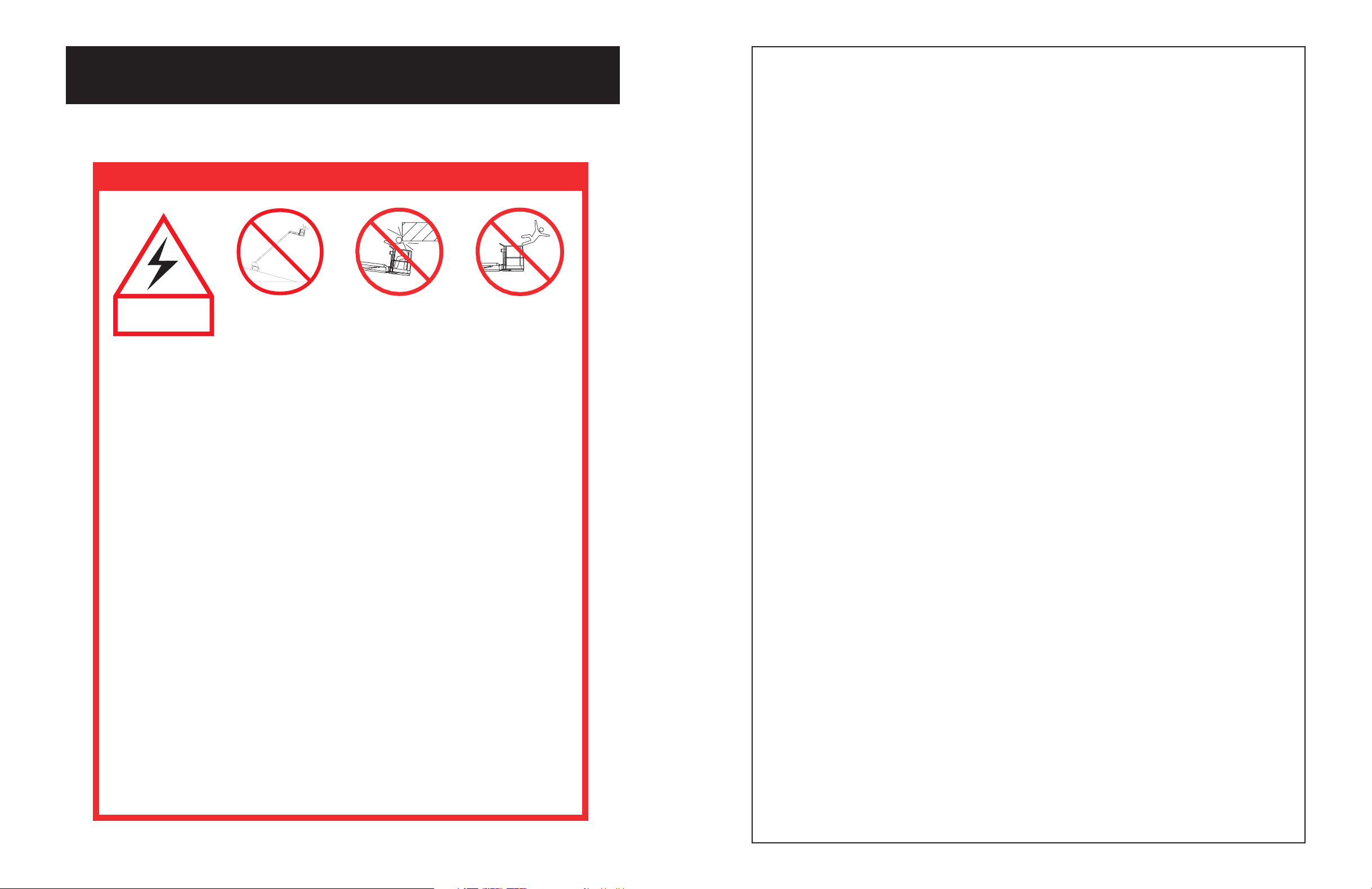
Electrocution Hazard Tip Over Hazard Collision Hazard Fall Hazard
ALL occupants must wear an approved fall restraint properly attached to designated platform
anchorage point. Attach only one fall restraint to each anchorage point.
NEVER exceed maximum platform load of 500 lbs. (225 kg) and two (2) occupants.
NEVER exceed 45 lbs. (200 N) of side force per occupant.
DISTRIBUTE all platform loads evenly on the platform.
NEVER operate the machine without first surveying the work area for surface hazards such as
holes, drop-offs, bumps, curbs, or debris; and avoiding them.
OPERATE machine only on surfaces capable of supporting wheel loads.
NEVER operate the machine when wind speeds exceed 28 mph (12.5 m/sec. = beaufort scale 6).
IN CASE OF EMERGENCY push emergency stop button to deactivate all powered functions.
ALWAYS close and secure sliding rail after entering platform.
NEVER exit or enter platform while elevated.
NEVER use ladders, scaffolding, or other items to gain height; work only from the platform floor.
NEVER climb down elevating assembly while platform is elevated.
INSPECT the machine thoroughly for cracked welds, loose or missing hardware, hydraulic leaks,
loose wire connections, and damaged cables or hoses before using.
VERIFY that all labels are in place and legible before using.
NEVER use a machine that is damaged, not functioning properly, or has damaged or missing
labels.
IF ALARM SOUNDS while boom is elevated, STOP, carefully retract boom and lower platform
without rotating. Move machine to a firm, level surface.
NEVER attach overhanging loads or use boom as a crane.
NEVER alter operating or safety systems without manufacturers written consent.
NEVER charge battery near sparks or open flame. Charging batteries emit explosive hydrogen
gas.
NEVER replace any component or part with anything other than original UpRight replacement
parts without the manufacturer's written consent.
NEVER tow the machine. Transport by truck or trailer only.
AFTER USE, secure the work platform from unauthorized use by turning both keyswitches off
and removing all keys.
SAFETY RULES
47
NOTES:
Page 3

46
NOTES:
3
Introduction
This manual covers the operation of internal combustion
powered models of the SB-60 Boom. This manual must
be stored on the machine at all times.
Pre-Operation and Safety
Inspection
Carefully read, understand and follow all safety rules,
labels, and operating instructions, then perform the
following steps each day before use.
Perform a complete visual inspection of the entire unit
prior to operating. Check the following areas for
discrepancies:
1. Open panels and check hydraulic components /
hoses for damage or leaks. Check electrical
components / wiring for damage or loose connections.
2. Inspect chassis, axles, hubs, rims, and steering
linkage for damage, deformation, loose or missing
hardware, and cracked welds.
3. Check tires for damage, punctures, and inflation (if
equipped with air filled tires); tire pressure must be
5.5 bars (80 psi).
4. Check all hoses for leakage / hoses and cables for
wear.
5. Inspect elevating assembly for damage, deformation,
loose or missing hardware, and cracked welds.
6. Inspect platform and guardrails for damage,
deformation, loose or missing hardware, and cracked
welds. Insure that the sliding rail operates freely.
7. Check Hydraulic fluid level with platform fully lowered.
8. Check fluid level in batteries (see Battery
maintenance, page 9).
9. Check fuel level, add fuel if necessary (see Fueling,
page 9).
10. Check engine oil level.
11. Check air filter. Replace if necessary.
NEVER remove the cap from a hot radiator. Hot
coolant can cause severe burns
12. Ensure that radiator is cold, check coolant level. Add if
necessary. Check radiator and hoses for damage.
If you smell propane, close the supply valve on
the tank immediately until you have located and
corrected the leak.
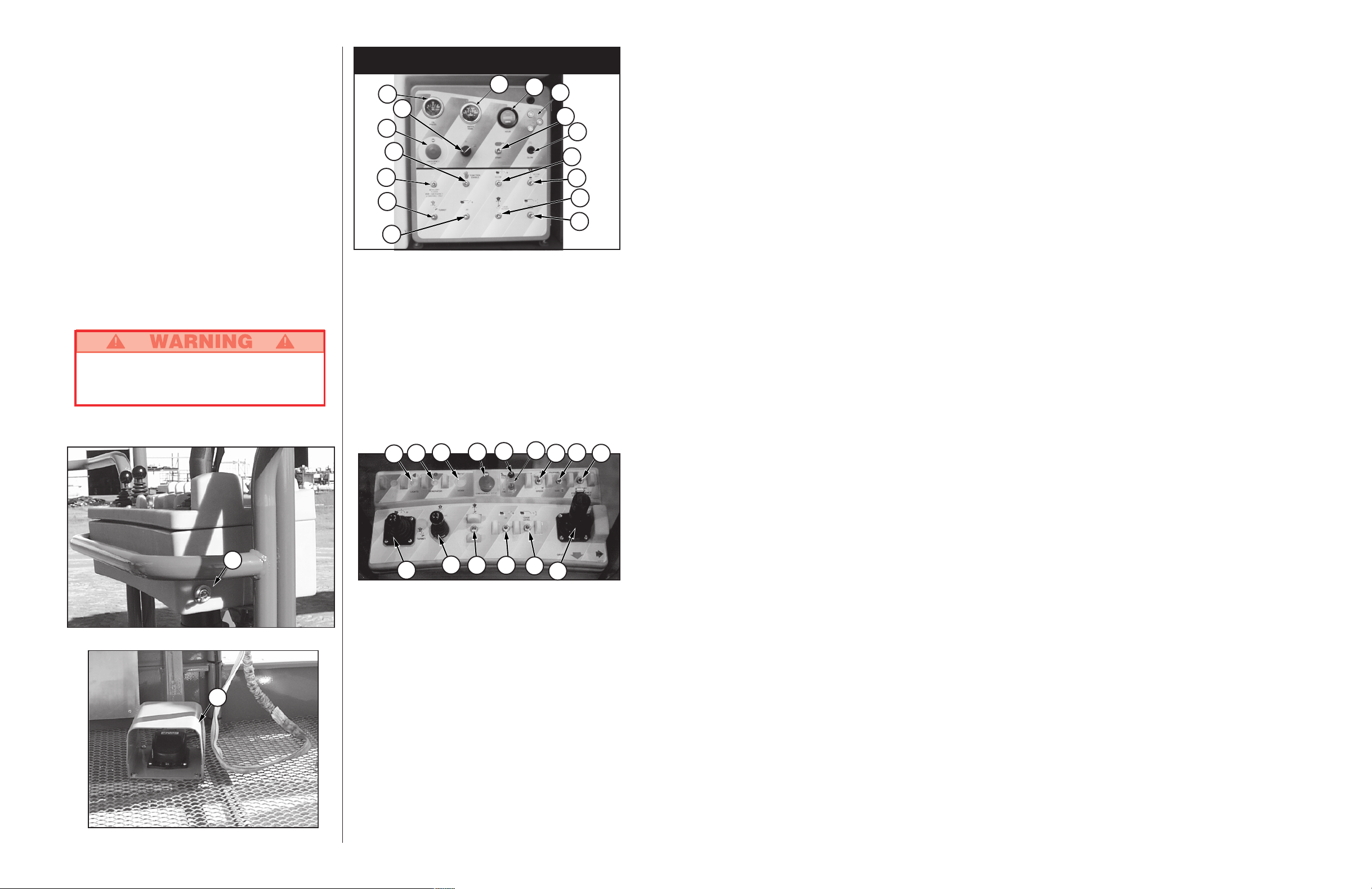
SYSTEM FUNCTION INSPECTION
Note: Refer to figures 2 through 5 for chassis and
platform control locations.
1. Before performing the following tests, check area
around machine and overhead for obstructions, holes,
drop-offs, and debris.
2. Turn chassis key switch to chassis, and pull out
emergency stop switches at the chassis control panel
and at the platform control panel.
3. Retract locking bolt. See figure 1.
4.
Press the engine start button to crank the engine;
release when engine starts. If engine is cold: press
the glow plug button button and hold for six seconds
prior to starting diesel models.
5. Push in the chassis emergency stop button, engine
should stop. Repeat for platform emergency stop
button. Return both emergency stop buttons to the on
position, and start engine.
6. Operate each function switch to raise / lower, extend /
retract, rotate left / right, each section of the elevating
assembly and observe the operation of the machine.
All functions should operate through full cycle
smoothly.
7. Turn chassis key switch to platform.
8. Mount the platform, attach approved fall restraint to
designated platform anchorage point. (If required by
National Legislation) Attach only one fall restraint to
each point.
9. While engaging the hand interlock, move the drive
control handle forward and reverse. Observe that
proportional functions operate smoothly, and that
brakes apply quickly after control is released.
10. While engaging the hand interlock, operate steer
switch to left and right. Observe that steering wheels
turn properly.
Figure 1: Locking bolt
Page 4
4
DO NOT use a machine that is damaged or
malfunctioning. Tag and remove the unit from
service until it is repaired.
11. While depressing foot switch, operate boom controls.
Observe that boom operates smoothly, and that boom
raise and lower, turret rotation, and boom extension
and retraction operate proportionally in conjunction
with stroke of handle. Observe that platform maintains
level when boom is elevated.
12. With the boom elevated five degrees above horizon or
greater, operate drive control handle. Observe that
drive speed should be no faster than (1 foot [0.30 m]
per second). Lower upper boom to stowed position.
13. Press the service horn button. Observe that horn is
audible.
NOTE: Hand interlock controls drive / steer
functions only.
NOTE: Foot switch interlock controls boom functions
only.
Figure 3: Platform Controls
Figure 2: Platform Controls
32
33
Controls and Indicators
Figure 5: Platform Controls
4
7
Figure 4: Chassis Controls
1
2
8
9
10
11
12
13
14
15
5
6
3
18
19
20
21
24
23
2217
31
30
2827
26
25
1. Oil pressure gauge
2. Water temperature gauge
3. Hourmeter
4. Emergency stop
5. Key switch
6. Engine start
7. Glow plug (Diesel only)
8. Auxiliary power for emergency lowering only
9. Function enable
10. Boom control
11. Boom extension control
12. Turret control
13. Jib control
14. Cage rotation
15. Cage level control
16. Circuit breaker
16
29
17. Generator (optional)
18. Horn button
19. Emergency stop
20. Tilt warning indicator
21. Low oil pressure indicator
22. Torque/Speed selector
23. Fuel selector (Gasoline only)/
Glow plug (Diesel only)
24. Auxiliary power for emergency lowering only
25. Boom/Turret control
26. Boom extension control
27. Cage rotate control
28. Jib control
29. Cage level control
30. Drive control handle/interlock
31. Lights (optional)
32. Engine start switch
33. Foot interlock switch
45
Electrical Schematic; SB-60 DIESEL
Schéma de câblage; SB-60 DIESEL
Elektrischer Schaltplan; SB-60 (Diesel)
Esquema eléctrico; SB-60 DIESEL
Page 5
Electrical Schematic; SB-60 DUAL FUEL
Schéma de câblage; SB-60 À DEUX COMBUSTIBLES
Elektrischer Schaltplan SB-60 (Zweistoff)
Esquema eléctrico; SB-60 DOBLE DIESEL
44
5
Starting the engine
From the lower controls
1. Turn the chassis key switch to chassis position.
2. Press the start button to crank the engine. Release
when the engine starts.
3. Diesel Engines: When the engine is cold, press and
hold the glow plug button for six seconds prior to
starting.
From the platform controls
1. Turn the chassis key switch to platform controls.
2. Turn the platform rotary switch fully clockwise to crank
the engine. Release when engine starts.
3. Diesel Engines: When the engine is cold, press and
hold the glow plug button for six seconds prior to
starting.
Driving
With Boom Lowered
1.
Turn chassis key switch to platform, and pull out the
chassis emergency stop switch.
2. Mount the platform, close the sliding rail. Make sure
that the sliding rail is safely closed. Keeping the
sliding rail open with the platform elevated (e.g. tying
down the sliding rail) is prohibited!
3. Attach approved fall restraint to designated platform
anchorage point. Attach only one fall restraint to each
point. (If required by National Legislation)
4. Start engine.
5. Check that the area around and above the work
platform is clear of obstructions, holes, drop-offs,
persons in the route of travel, and the surface is
capable of supporting wheel loads.
6. Engage the interlock switch and move the drive
control handle forward to travel forward and rearward
to travel in the reverse direction.
Note: When the boom is rotated to the front of the
chassis (steering wheels aft) directions of travel and
steering will be reversed. Observe the color coded
arrows on the control panel near the drive control
handle, and on the chassis. They will indicate the
direction of travel when the drive control handle is
moved.
Operation
Before operating work platform insure that:
Pre-operation and safety inspection has been
completed, and any discrepancies have been
corrected.
System function inspection has been performed.
Operator has been thoroughly trained on the
operation of the machine.
Work area is clear of all obstructions, holes, drop-
offs, or persons in the route of travel.
Surface is capable of supporting wheel loads.
Refer to figures 2 through 5 for control locations.
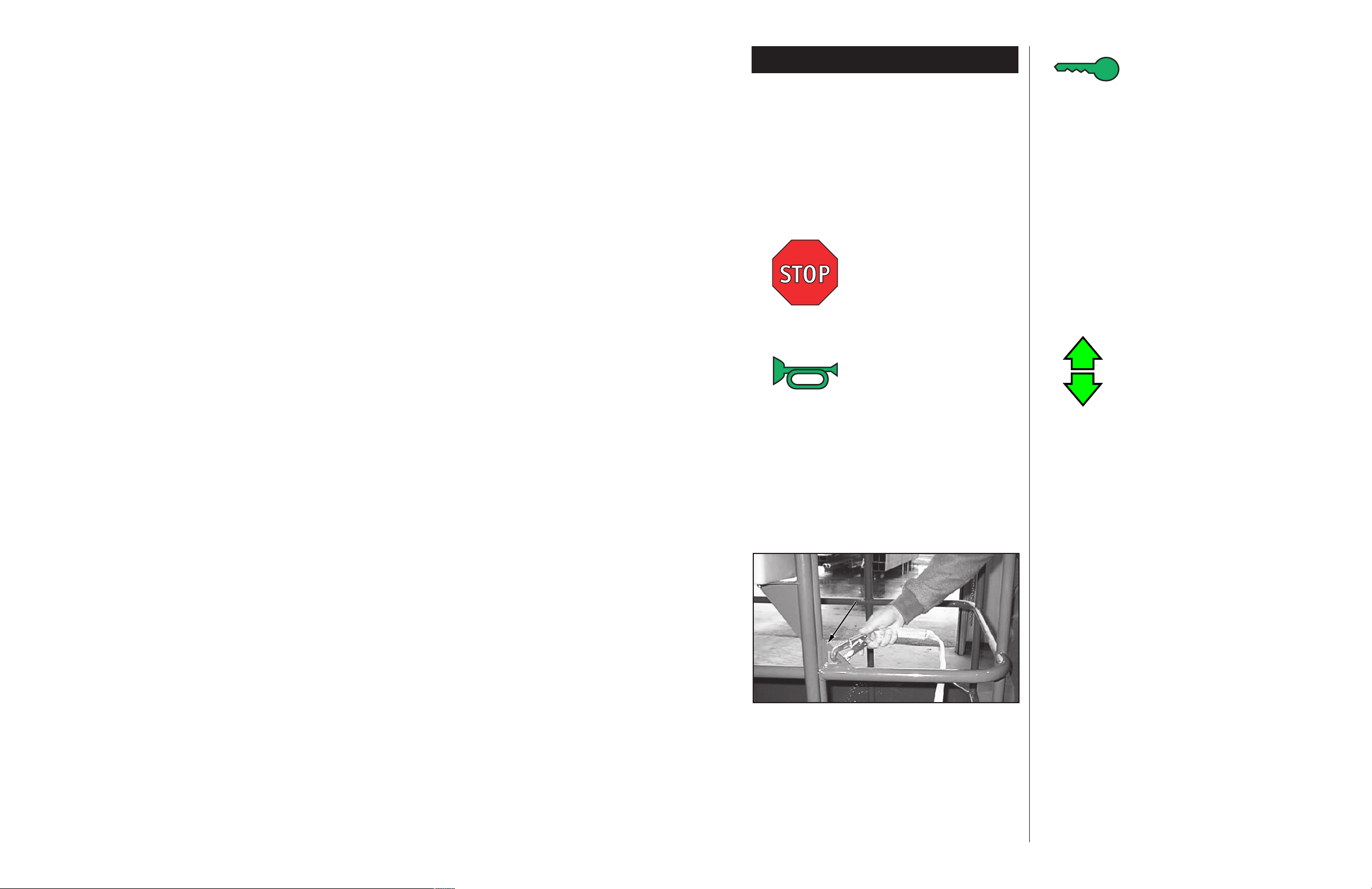
Emergency Stop
At any time during operation, press the emergency stop
button to stop all functions in an emergency.
Service Horn
At any time during operation, press the service horn
button to sound an audible warning if necessary.
Figure 6: Typical Fall Restraint Anchorage Point
NOTE: Always wear an approved fall restraint
properly attached to designated platform anchorage
point when driving or elevating the machine. (If
required by National Legislation) (see figure 6).
Attach only one fall restraint to each anchorage point.
Page 6

6
With Boom Elevated
Travel with boom elevated is restricted to firm level
surfaces only.
When driving elevated, the machine will travel at creep
speed (0.30 m [1 foot] per second).
Steering
1. While engaging the hand interlock, push the steering
switch (located on top of the control handle) to the left
to turn left, and right to turn right.
Note: Steering is not self centering. Wheels must be
returned to the straight ahead position by operating
the steering switch.
POSITIONING THE PLATFORM
Positioning the platform as close as possible to the work
area requires some planning. First, you must survey the
work site to find a suitable place to park the machine. This
must be a firm level area as close as possible to the work
area. Take into consideration all obstructions on the
ground and overhead and avoid them.
Always, before operating any function, check the area
around and overhead for any obstructions or electrical
conductors.
Multifunction Controls
The UpRight SB-60 employs the use of multifunction
controls. This means that any two functions can operate
at full speed simultaneously.
The turret may be rotated while driving if necessary to
make turns in tight areas. All other boom functions will not
operate while driving.
Lower Control Operation
Do not operate from lower controls if someone is in
platform, except in emergency situations.
All boom functions will operate at fixed speed.
1. Turn chassis keyswitch to chassis controls.
2. With engine running, operate boom control switches
to position the platform.
Leveling the Platform
DO NOT operate the machine if the platform does
not maintain level when elevated.
Note: Platform leveling can be performed only with
the boom stowed and should be done only to
calibrate the automatic leveling system.
While depressing the foot switch, move the platform
level control switch forward to swing the platform
upward, rearward to swing the platform downward.
Release the switch to stop leveling. Leveling can be
performed only when boom is stowed and retracted.
Rotating the Turret
While depressing the foot switch, move the boom
rotation joystick to the right to rotate right, left to rotate
left. Release the switch to stop rotation. The turret
rotation will function at a speed proportional to the
stroke of the joystick. Make sure the area around the
boom is clear of all obstructions before rotating the
turret.
Elevating the Boom
While depressing the foot switch, move the joystick
forward to elevate the boom, rearward to lower the boom.
Release the control lever to stop elevating / lowering. The
boom elevate will function at a speed proportional to the
stroke of the joystick.
Extending the Boom
While depressing the foot switch, move the boom
extension control joystick rearward to extend the
boom, forward to retract the boom. Release the
control lever to stop extending / retracting. The boom
extension will function at a speed, proportional to the
stroke of the joystick.
43
Hydraulic Schematic; SB-60
Schéma hydraulique; SB-60
Hydraulikschaltplan; SB-60
Esquema hidráulico; SB-60
Page 7
42
06-BSCITAMEHCSCILUARDYHTHGIRPU
000-720001.ONTRAP
HSILGNESIAÇNARFNAMREGHSINAPS
PMUDTNEMESREVÉDgnureeltnEAGRACSED
DEELBDEEPSWOLESSETIVESSAB,EGRUPgnutfültnegnaghceirKDADICOLEVAJABAAGRUP
SSAPYBNOITAVIRÉDssapyBNÓICAVIRED
RETLIFERTLIFretliFORTLIF
PMUPYRAILIXUAERIAILIXUAEPMOPepmupsfliHRAILIXUAABMOB
PMUPEPMOPepmuPABMOB
RENIARTSNOITCUSNOITARIPSA'DENIPÉRCbeisguasnANÓICARIPSAEDORTLIF
PMUPCITATSORDYHEUQITATSORDYHEPMOPepmupkcurdlÖACITÁTSORDIHABMOB
REETSNOITCERIDnekneLRIGIRID
TFILEGAVELnebeHNÓICAVELE
GNIWSNOITALLICSOneknewhcSOECNALAB
DNETXEEGNOLLARnerhafsuANÓISNETXE
LEVELUAEVINnereilleviNLEVIN
GNIWSNOITALLICSOneknewhcSOECNALAB
RETSAMERTÎAMlitnevtpuaHORTSEAM
EVALSEVALCSElitnevegloFOVALCSE
REWOPMOOBEHCÈLF,.MILAlitnevtfarkregelsuAAMULPALEDAÍGRENE
ROTATORMROFTALP-ETALP,NOITATORED.PSID
EMROF
gnuknewhcsnenhübstiebrAALEDNÓICATOR
AMROFATALP
EKARBNIERFesmerBONERF
KCOLELXAUEISSE'LEDEGALLIUORREVerrepsshcAEJELEDORUGES
GNILPUOCYRATOR.PSID,TNEMELPUOCCA
FITATOR
ßulhcsnaherDOVITATOROTNEIMALPOCA
RAERTFELEHCUAG,ERÈIRRAsknilnetnihODREIUQZIORESART
TNORFTFELEHCUAG,TNAVAsknilnrovODREIUQZIORETNALED
RAERTHGIRETIORD,ERÈIRRAsthcernetnihOHCEREDORESART
TNORFTHGIRETIORD,TNAVAsthcernrovOHCEREDORETNALED
REDIVIDWOLFECIRTUBIRTSIDENNAVrelietsgnumörtSOJULFEDROSIVID
ELXAGNITALICCOTNALLICSOUEISSEeshcalednePETNALICSOEJE
GNIREETSNOITCERIDgnukneLNÓICCERID
7
Elevating the Jib
While depressing the foot switch, move the jib
control switch forward to elevate the jib, rearward
to lower the jib. Release the control lever to stop
elevating / lowering.
Rotating the Platform
While depressing the foot switch, toggle the control
switch left to rotate left, right to rotate right. Release
the switch to stop rotation.
EMERGENCY OPERATION
In the event of a malfunction, the elevating assembly may
be lowered using the following procedure.
NEVER climb down the elevating assembly. If
controls do not respond, follow the emergency
lowering procedure.
Lowering Elevating Assembly
1. Engage the auxiliary power unit switch.
2. Operate any boom function in the normal manner.
Note: Auxiliary battery is capable of one emergency
lowering cycle before requiring recharge.
Battery is recharged while engine is in
operation.
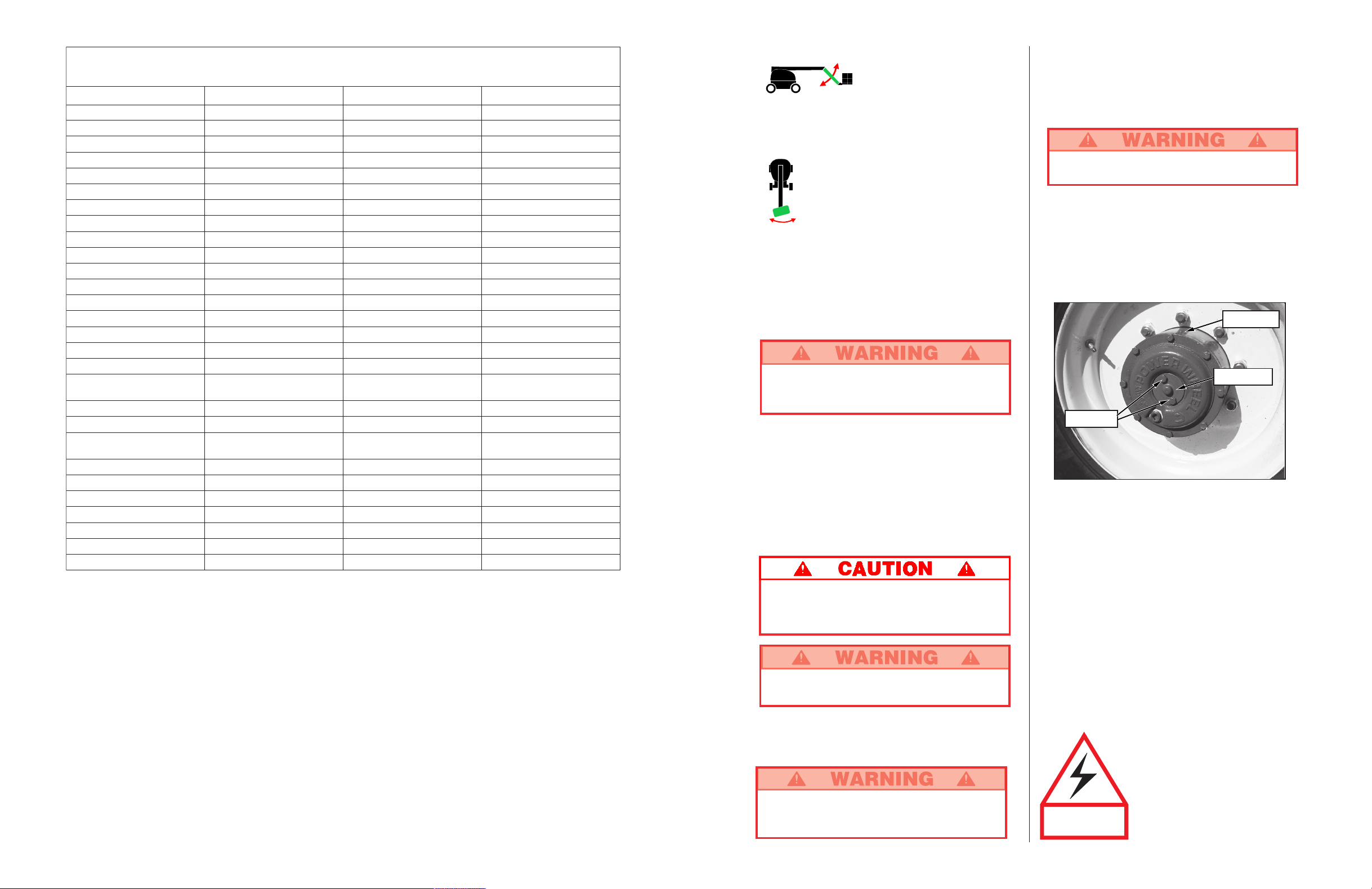
EMERGENCY TOWING
DO NOT tow the machine faster than 5 km/h
(3 mph). Faster speeds will damage drive
components and void warranty.
There are no brakes when the center caps are
installed in the inverted position.
Perform the following only when the machine will not
operate under its own power and it is necessary to move
the machine or when winching onto a trailer for
transportation.
DO NOT use a machine that is damaged or
malfunctioning. Tag and remove the unit from
service until it is repaired.
1. Insure that the platform is fully lowered, and that
the turret is rotated so that the platform is to the
rear of the machine.
2. Refer to figure 7 and disengage all four drive hubs.
Remove two (2) cap screws and center cap.
Reinstall center cap in the opposite direction.
Chock wheels before disengaging hubs. Machine
may roll.
3. When ready to move the machine, remove the
chocks. Tow or winch into position and replace
chocks.
4. Attach adequate chain/cable of sufficient strength for
towing the machine to the front or rear tie down lugs.
5. Engage all four drive hubs by returning the center
caps to their original orientation.
Switching Fuels (Gas / Propane Only)
1. With the engine running, push the Fuel Selector
Switch to the center position.
2. After the engine has quit running, select the
appropriate fuel supply.
3. Restart the engine.
AFTER USE EACH DAY
1. Ensure that the platform is fully lowered.
2. Park the machine on level ground, preferably under
cover, secure against vandals, children or
unauthorized operation.
3. Turn the key switch to OFF and remove the key to
prevent unauthorized operation.
Figure 7: Drive Hub (Operating position shown)
Drive Hub
Center Cap
Screws
THIS MACHINE IS
NOT INSULATED.
This machine is not insulated.
Follow your national safety
standards and maintain the
required safety distance when
working near energized equipment.
Page 8
8
BY CRANE
Stand clear of machine when lifting.
Check specifications on back page, insure that
crane and slings are of correct capacity to lift
weight of unit.
1. Insure that boom is fully lowered and retracted.
2. Attach straps to chassis lifting lugs only. Insure that
straps are adjusted properly to keep unit level when
lifting.
BY TRUCK OR TRAILER
1. Insure that boom is fully lowered and retracted.
2. Maneuver the machine onto bed of truck / trailer.
3. When winching, follow instructions for emergency
towing on page 7. Attach adequate winch cable of
sufficient strength to front tie down lugs.
Transportation
Do not winch machine faster than 5 km/h (3 mph.)
4. After winching, insure that all four drive hubs are
engaged by returning the center caps to their original
orientation.
5. Secure the machine to the transport vehicle using
chains / straps of adequate load capacity (refer to
specifications, back page) attached to chassis tie
down lugs (see figures 8 and 10).
6. Place wooden block (10cm x 10cm x 91cm)
(4" x 4" x 36") under platform support braces.
(Figure 9)
7. Attach ratchet strap under platform floor grating,
over support braces. (Figure 9) Do not over tighten.
Elevating boom functions while on transport
vehicle is prohibited except during loading and
unloading.
Figure 10: Rear chassis tie down lifting lugs.
Figure 9: Securing the machine for transportation.
Figure 8: Front chassis tie down lifting lugs.
Platform Tie Down Strap
Wooden Block
4" x 4" x 36"
Support Braces
Chassis Tie Down Lifting
Lugs
Chassis Tie Down
Lifting Lugs
41
Especificaciones**
* Especificaciones sujetas a modificación sin aviso previo.
Ver información completa sobre componentes y mantenimiento en el Manual de mantenimiento.
ÍTEM ESPECIFICACIÓN
Altura
Altura máxima de trabajo 20,3 m (66 pies)
Altura máxima de la plataforma 18,3 m (60 pies)
Pasa en la plataforma en altura 0,15 m (6 plg)
Altura en conducción 18,3 m (60 pies)
Alcance horizontal 16 m (52 pies 8 plg)
Rotación de la torre 360 grados continuous
Rotación de la plataforma 180 grados
Oscilación de la cola 1,35 m (53 plg)
Longitud del brazo 2,4 m (8 pies)
Arco del brazo 150 grados
Radio de giro interno 3,96 m (13 pies)
Radio de giro externo 6,76 m (22 pies 2 plg)
Velocidad de conducción (reducida) 6,4 km/h (4 mph)
Velocidad de conducción (elevada) 1,2 km/h (0,7 mph)
Gradabilidad 24grados / 45%
Nivel de ruido 80 dB
Presión del suelo 80 psi/presión de los neumáticos
rellenos con aire
Dimensiones (pluma recogida)
Tamaño de la plataforma 1,0 m x 1,83 m. opc 1,0 m x 2,44 m
(39 plg x 72 plg opc 39 plg x 96 plg)
Altura de la baranda 1,14 m (45 plg)
Tabla de pie 0,15 m (6 plg)
Cantidad máxima de ocupantes 2 más carga adicional
Peso/Gasolina 10 705 kg (23 600 lbs)
Peso/Diesel 10 750 kg (23 700 lbs)
Altura total (almacenado) 2,6 m (8 pies 6 plg)
Longitud total (almacenado) 9,07 m (29 pies 9 plg)
Ancho total 2,43 m (7 pies 11,75 plg)
Base de la rueda 2,59 m (8 pies 6 plg)
Banda de rodamiento de la rueda 1,5 m (59 plg)
Terreno libre 0,29 m (11,5 plg)
Fuente de energía / combustible GM 3,0 Liter
Fuente de energia / diesel Perkins 704-30
Voltaje del sistema 12 VDC
Presión hidráulica máxima 345 bars (5000 psi)
Controles Proporcional eléctrico
Neumáticos con rodadura número 14/80 psi
ÍTEM
ESPECIFICACIÓN
DIAGRAMA DE ALCANCE ENVOLVENTE
DIMENSIONES EN METROS
Page 9

40
Referencias de la Tabla de mantenimiento
de rutina
Intervalo
Diario = cada turno (todos los días) o cada ocho horas
30
D
= cada mes (30 días) o cada cincuenta horas
3
M
= cada 3 meses o cada 125 horas
6
M
= cada 6 meses o cada 250 horas
1
A
= cada año o cada 500 horas
2
A
= cada dos años o cada 1000 horas
S = Sí / aceptable
N = No / No aceptable
R = Reparada / Aceptable
Tabla de mantenimiento de rutina
MANTENIMIENTO DE RUTINA
Usar la tabla siguiente como guía para mantenimiento de
rutina. La inspección y el mantenimiento serán
realizados por personal entrenado y con experiencia
en mecánica y electricidad. Ver las instrucciones de
mantenimiento en el Manual de mantenimiento.
Fotocopiar esta página y usar la Tabla de mantenimiento
de rutina como hoja de control al inspeccionar una
máquina.
Informe de mantenimiento
Fecha:
Propietario:
Modelo No.: No. de serie:
Realizó mantenimiento:
Intervalo de mantenimiento:
COMPONENTE INSPECCIÓN O SERVICIOS INTERVALO S N R
Estructura Inspección de rajaduras estructurales Diario
elevadora Control de desgaste de pivotes 30D
Control de torsión correcta de tornillos
30
D
de retención de pasador de pivote
Control de deformación de partes Diario
Chasis Control de deformación o desgaste de las mangueras Diario
Controlar torsión correcta de montaje de componentes 6M
Revise el perno del apoyo de péndulo (par de torsión
123 Nm) (90 libras-pies)
6M
Control de soldaduras resquebrajadas Diario
Torre Control lubricación y desgaste de engranajes de anillos Diario
Revise el nivel del aceite 150H/3M
Lubricación de cojinetes de anillos (grasa MoS2) 150H/3M
Cubos de Control de fugas Diario
desplazamiento
Control de nivel de aceite 250H/6M
Cambio de aceite después de período de rotura 50H/30D
Cambio de aceite (aceite de engranajes SAE 90 wt.) 2000H/2A
Ajuste los elementos de montaje de las tasas a un
par de torsión de 123 Nm (90 libras-pie)
6M
Cilindros de Control de desgaste de varillas de cilindros 30D
elevación Control de torsión correcta de tornillos de
30
D
retención de pasadores de pivote
Control de fugas en sellos 30D
Inspección de desgaste de pivotes 30D
Control de torsión correcta de conectores 30D
Unidad Control y reparación de daño por colisión Diario
completa Control de torsión correcta de pasadores 3M
Control de corrosión, retirar y pintar 3M
Lubricación 30D
Etiquetas Control de estado, legibilidad o falta
Diario
de etiquetas, reemplazar
COMPONENTE INSPECCIÓN O SERVICIOS INTERVALO S N R
Aceite del Control de nivel y estado Diario
motor
Control de fugas Diario
Cambio de aceite y filtro (Combustible doble) 200HORAS
Cambio de aceite y filtro (Diesel) 500HORAS
Sistema de Control de nivel de combustible Diario
combustile
Control de fugas Diario
Reemplazo de filtro de combustible 6M
Verificar filtro de aire Diario
Baterías Contol de nivel de electrólitos Diario
Limpieza exterior 3M
Limpieza de terminales 3M
Refrigerante Control de nivel de refrigerante (con motor frío) Diario
del motor Reemplazo de refrigerante 2A
Aceite Control de nivel de aceite Diario
hidráulico Cambio de filtro 6M
(*vea nota) Drenaje y reemplazo con aceite compatible ISO 46 2A
Sistema Control de fugas Diario
hidráulico Control de conexiones de mangueras 30D
Control de desgaste exterior de mangueras 30D
Sistema Control de funcionamiento de anulador de
Diario
hidráulico de emergencia unidad de energía Diario
emergencia
Controlador Control de funcionamiento de todos los controles Diario
Cable de Verifique que la parte exterior del cable no se encuentre
control apretada, amarrada o gastada.
Diario
Piso y rieles Control de torsión correcta de pasadores Diario
de la Control de soldaduras resquebrajadas Diario
plataforma Control del estado de la plataforma Diario
Control de estado de puntos de anclaje Diario
Control de estado del manual del operador Diario
Neumáticos Control de daños Diario
Controlar la presión de aire (excepto rellenas con
gomaespuma) (5.5 bar [80 psi])
Diario
Control tuercas de anillos de amarre
(torsión 123 Nm [90 libras-pie])
30D
Bomba Limpieza 30D
hidráulica Control de fugas en superficies de unión 30D
Control de fugas en accesorios de mangueras Diario
Control de torsión correcta en tornillos de montaje 30D
Sistema de Control de funcionamiento de motor hidráulico Diario
conducción Control de fugas en mangueras, conectores
Diario
hidráulica y válvulas de bloqueo
Sistema de Control de par de torsión en conectores 6M
dirección Control de péridas en cilindro de dirección 30D
Control de zonas de desgaste en en enlace 30D
Control de retenes flojos o faltantes Diario
*Mobil DTE 15M, ISO grado 46, para un promedio de temperaturas de entre 4,4oC y
43,3
o
C (40oF y 110oF)
*Para climas más fríos:
Mobil DTE 13M, ISO grado 32, para un promedio de temperaturas de entre -12,2
o
C y
18,3
o
C (10oF y 65oF)
9
BATTERY MAINTENANCE
Hazard of explosive gas mixture. Keep sparks,
flame and smoking materials away from batteries.
Always wear safety glasses when working with
batteries.
Battery fluid is highly corrosive. Rinse away any
spilled fluid thoroughly with clean water.
Check battery fluid level daily, especially if work platform
is being used in a warm, dry climate.
If electrolyte level is lower than 10 mm (3/8 in.) above
plates add distilled water only. DO NOT use tap water it
will shorten battery life.
Keep terminals and top of battery clean.
TIRES
Tire selection can affect the stability of the machine. Use
only tires supplied by UpRight (15-19.5 NHS Tubeless 14
Ply Rating) unless approved by the manufacturer in
writing. If equipped with air filled tires, check tire air
pressure daily. 5.5 bars (80 psi).
FUELING
Gasoline
1. Open left turret cover, open fill pipe cap. (see
figure 11)
2. Fill to capacity with unleaded motor fuel only.
3. Fuel tank full capacity is 159 L (42 US gallons).
Diesel
1. Open left turret cover, open fill pipe cap. (see
figure 11)
2. Fill to capacity with diesel motor fuel only. Use
distillate fuel only, do not use residual or blend.
3. Fuel tank full capacity is 159 L (42 US gallons).
HYDRAULIC OIL
1. Open left turret cover and check oil level at sight
gauge with the boom stowed and retracted. Engine
running or stopped. (see figure 12)
2. If necessary, fill to capacity with clean ISO 46
compatible hydraulic oil. Refer to Routine Service
table on page 10.
3. Clean area around cap before opening.
4. Open filler / breather cap to add hydraulic oil.
5. Replace cap.
6. Properly dispose waste hydraulic oil.
LUBRICATION
Refer to service manual for lubrication chart and
guidelines.
Maintenance
Figure 11: Fuel tank
Fuel cap
Figure 12: Hydraulic Oil Tank
Hydraulic Oil Filler / Breather Cap
Hydraulic Oil Level Gauge
Page 10

10
COMPONENT INSPECTION OR SERVICES INTERVAL Y N R
Elevating Inspect for structural cracks Daily
Assembly Check pivot points for wear 30D
Check pivot pin retaining bolts for proper torque 30D
Check members for deformation Daily
Chassis Check hoses for pinch or rubbing points Daily
Check component mounting for proper torque 6M
Check swing bearing bolt (torque
to 123 Nm [90 ft. lbs.])
6M
Check welds for cracks Daily
Turret Check ring gear for proper lubrication and wear Daily
Check planetary oil level 150H/3M
Lubricate ring gear (MoS
2
grease) 150H/3M
Torque Check for leaks Daily
Hubs Check oil level 250H/6M
Change oil after break-in period 50H/30D
Change oil (SAE 90 wt. gear oil) 2000H/2Y
Torque hub mounting hardware to
123 Nm [90 ft. lbs.]
6M
Lift Check the cylinder rods for wear 30D
Cylinders Check pivot pin retaining bolts for proper torque 30D
Check seals for leaks 30D
Inspect pivot points for wear 30D
Check fittings for proper torque 30D
Entire Check for and repair collision damage Daily
Unit Check fasteners for proper torque 3M
Check for corrosion, remove and repaint 3M
Lubricate 30D
Labels Check for peeling, missing, or unreadable
Daily
labels & replace
COMPONENT INSPECTION OR SERVICES INTERVAL Y N R
Engine Oil Check level and condition Daily
Check for leaks Daily
Change oil & filter (Dual Fuel) 200HOURS
Change oil & filter (Diesel) 500HOURS
Engine Fuel Check fuel level Daily
System Check for leaks Daily
Replace fuel filter 6M
Check air cleaner Daily
Batteries Check electrolyte level Daily
Clean exterior 3M
Clean terminals 3M
Engine Check coolant level (with engine cold) Daily
Coolant Replace coolant 2Y
Hydraulic Check oil level Daily
Oil Change filter 6M
(*See note ) Drain and replace with ISO 46 compatible oil 2Y
Hydraulic Check for leaks Daily
System Check hose connections 30D
Check hoses for exterior wear 30D
Emergency Check operation of emergency override power unit Daily
Hydraulic
System
Controller Check operation of all controls Daily
Control Check the exterior of the cable
Daily
Cable for pinching, binding or wear
Platform Check fasteners for proper torque Daily
Floor and Check welds for cracks Daily
Rails Check condition of platform Daily
Check condition of anchorage points Daily
Check condition of operators manual Daily
Tires Check for damage Daily
Check air pressure (except foam filled)
(5.5 bar [80 psi])
Daily
Check lug nuts (torque to 123 Nm [90 ft. lbs.]) 30D
Hydraulic Wipe clean 30D
Pump Check for leaks at mating surfaces 30D
Check for hose fitting leaks Daily
Check mounting bolts for proper torque 30D
Hydraulic Check hydraulic drive motor operation Daily
Drive System Check hoses, fittings, and valve block for leaks Daily
Steering Check fittings for proper torque 6M
System Check steering cylinder for leaks 30D
Check linkage for wear areas 30D
Check for missing / loose retainers Daily
Interval
Daily=each shift (every day) or every eight hours
30
D
=every month (30 days) or every 50 hours
3
M
=every 3 months or 125 hours
6
M
=every 6 months or 250 hours
1
Y
=every year or 500 hours
2
Y
=every 2 years or 1000 hours
Y=Yes/Acceptable
N=No/Not Acceptable
R=Repaired/Acceptable
Routine Service Table
Service Report
Date: _________________
Owner: _________________
Model No: _____________ Serial No: _____________
Serviced By: _____________
Service Interval: __________
ROUTINE SERVICE
Use the following table as a guide for routine
maintenance. Inspection and maintenance shall be
performed by personnel who are trained and familiar
with mechanical and electrical procedures. Refer to
the Service Manual for complete service instructions.
Please copy this page and use the Routine Service Table
as a checklist when inspecting a machine for service.
Routine Service Table Key
*Mobil DTE 15M, ISO grade 46, for temperature range of 40oF up to
110
o
F.
*For colder climates:
Mobil DTE 13M, ISO grade 32, for temperature range of 10
o
F up to
65
o
F.
39
MANTENIMIENTO DE LA BATERÍA
Peligro de mezcla de gases explosiva. Mantener
la batería lejos de chispas, llama o humo.
Usar siempre anteojos de seguridad al trabajar
con baterías.
El fluido de la batería es muy corrosivo. Lavar
bien los derrames de fluido con agua limpia.
Controlar diariamente el nivel del fluido, especialmente si
se usa la plataforma en clima seco y cálido.
Si el nivel de electrolitos sobre las placas es inferior
a 10 mm (
3
/8 plg) sólo agregar agua destilada.
NO usar agua potable ya que acorta la vida de la batería.
Mantener limpias las terminales y la tapa de la batería.n.
NEUMÁTICOS
La elección de los neumáticos puede afectar la
estabilidad de la máquina. Sólo usar los neumáticos de
UpRight (15-19.5 NHS sin tubos, 14 espesor nominal),
salvo autorización escrita del fabricante. Si viene
equipada con neumáticos rellenos con aire, verifique la
presión de los neumáticos diariamente, 5,5 bars (80 psi).
COMBUSTIBLE
Gasolina
1. Abra la cubierta de la torre izquierda, abra la tapa del
caño de llenado (ver figura 11).
2. Llenar solamente con combustible para motores sin
plomo.
3. La capacidad total del tanque es de 159 lts.
(42 galones).
Diesel
1. Abra la cubierta de la torre izquierda, abra la tapa del
caño de llenado (ver figura 11).
2. Llenar solamente con combustible para motores
diesel. Solo usar combustible destilado, no usar
residual o mezcla.
3. La capacidad total del tanque es de 159 lts.
(42 galones).
ACEITE HIDRÁULICO
1. Abra la cubierta de la torre izquierda y revise el nivel
del aceite en el indicador con la pluma guardada y
contraída. El motor en marcha o detenido. (ver
figura 12)
2. Si es necesario, llenar con aceite hidráulico
compatible ISO 46. Vea el cuadro de Mantenimiento
de rutina en la página 40.
3. Limpiar el área de alrededor de la tapa antes de
abrirla.
4. Abrir la tapa de llenado y respiración y agregar aceite.
5. Tapar de nuevo.
6. Desechar el aceite hidráulico apropiadamente
LUBRICACIÓN
Ver cuadro de lubricación e instrucciones en el manual de
mantenimiento.
Mantenimiento
Figura 11: Tanque de combustible
Tapa de
combustible
Figura 12: Tanque de aceite hidráulico
Tapa de llenado / respirador
de aceite hidráulico
Indicador de nivel
del aceite hidráulico
Page 11

38
POR GRÚA
Pararse lejos de la máquina cuando ésta es
levantada.
Ver las especificaciones en la última página,
controlar que la grúa y las eslingas tengan la
capacidad adecuada para levantar el peso de la
unidad.
1. Verificar que la pluma esté totalmente baja y
replegada.
2. Sólo colocar correas en los anillos de amarre del
chasis. Las correas deben estar bien ajustadas para
mantener la unidad nivelada al levantarla.
POR CAMIÓN O TRÁILER
1. Verificar que la pluma esté totalmente baja y retraida.
2. Colocar la máquina en el piso del camión o tráiler.
3. Para levantar la unidad seguir las instrucciones para
remolque de emergencia en la página 37. Colocar el
cable del cabrestante adecuado de suficient fuerza en
los anillos de amarre delanteros.
No levantar la máquina a una velocidad superior
a 5 km/h (3 millas por hora).
4. Después de levantar, verificar que las cuatro tasas
estén colocadas volviendo las tapas centrales a su
orientación original.
5. Asegurar la máquina al vehículo de transporte
usando cadenas o correas de capacidad de peso
adecuadas en los anillos de amarre del chasis
(ver especificaciones en la última página) (ver
figuras 8 y 10).
6. Colocar un bloque de madera (10 cm x 10 cm x 91 cm)
(4 plg x 4 plg x 36 plg) debajo de las barras de apoyo
de la plataforma. (figura 9)
7. Colocar una correa de trinquete debajo del enrejado
del piso de la plataforma, sobre las barras de apoyo.
(figura 9). No ajustar en exceso.
La funciones de elevación de la pluma están
prohibidas mientras que se encuentra en el
vehículo de transporte, excepto durante la carga
y descarga.
Transporte
Figura 10: : Anillos de amarre traseros para elevación
del chasis
Figura 9: Asegurar la máquina para transporte
Figura 8: Anillos de amarre delanteros para elevación
del chasis
Correa de amarre
de la plataforma
Bloque de madera
10 cm x 10 cm x 91 cm
(4 plg x 4 plg x 36 plg )
Barra de apoyo
Anillas de amarre para
elevación del chasis
Anillas de amarre para
elevación del chasis
11
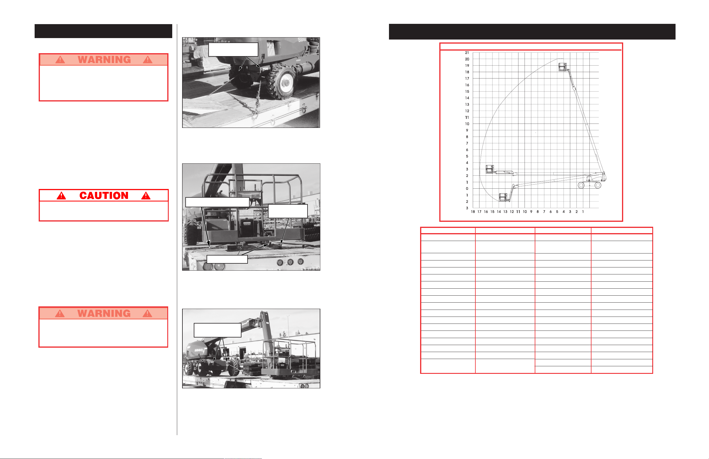
Specifications*
* Specifications subject to change without notice.
Refer to Service Manual for complete parts and service information.
ITEM SPECIFICATION
Height
Working height maximum 20.3 m (66 ft.)
Platform height maximum 18.3 m (60 ft.)
Platform step in height 0.15 m (6 in.)
Drivable height 18.3 m (60 ft.)
Horizontal outreach 16 m (52 ft. 8in.)
Turret rotation 360 deg. continuous
Platform rotation 180 deg.
Tail swing 1.35 m (53 in.)
Jib length 2.4 m (8 ft.)
Jib arc 150 deg.
Inside turning radius 3.96 m (13 ft)
Outside turning radius 6.76 m (22 ft. 2 in.)
Drive speed (lowered) 6.4 km/h (4 mph)
Drive speed (elevated) 1.2 km/h (.7 mph)
Gradability 24deg. / 45%
Noise Level 80 dB
Ground Pressure 80 psi/ Air filled tire pressure
Dimensions (boom stowed)
Platform Size 1.0 x 1.83m. opt 1.0 x 2.44 m
(39 in. x 72 in. opt 39 in. x 96 in.)
Guardrail height 1.14 m (45 in.)
Toeboards 0.15 m (6 in.)
Maximum no. of occupants 2 Plus additional load
Weight \ Gasoline 10,705 kg (23,600 lbs.)
Weight \ Diesel 10,750 kg (23,700 lbs.)
Overall height (Stowed) 2.6 m (8 ft. 6 in.)
Overall length (Stowed) 9.07 m (29 ft. 9 in.)
Overall width 2.43 m (7 ft. 11.75 in.)
Wheel base 2.59 m (8 ft. 6 in.)
Wheel track 1.5 m (59 in.)
Ground Clearance 0.29 m (111/2 in.)
Power source \ Gasoline GM 3.0 Liter
Power source \ Diesel Perkins 704-30
System voltage 12VDC
Maximum Hyd. Pressure 345 bar (5000 psi)
Controls Electric Proportional
Tires 14 ply lug tread/80 psi
ITEM SPECIFICATION
REACH ENVELOPE DIAGRAM
DIMENSIONS IN METERS
Page 12

12
CETTE MACHINE
NEST PAS ISOLÉE.
NE JAMAIS utiliser le
bras articulé à flèche
ni conduire plateforme élevée sans
que la machine ne
soit sur une surface
horizontale solide.
NE JAMAIS positionner
la plate-forme sans
sêtre dabord assuré
quil ny a pas
dobstacles ou autres
sources de danger aux
alentours.
NE JAMAIS monter,
sasseoir ou se tenir
debout sur les rampes
du garde-corps.
Danger délectrocution Danger de basculement Danger de collision Danger de chute
TOUS les occupants doivent porter un dispositif antichute dun modèle approuvé, correctement fixé au
point de fixation désigné à cet effet de la plate-forme. Ne fixer quun dispositif antichute par point de
fixation.
NE JAMAIS dépasser la charge maximale de la plate-forme, établie à 225 kg (500 lb) et à deux (2)
occupants.
NE JAMAIS dépasser une force latérale par occupant de 200 N (45 lb).
RÉPARTIR également toutes les charges sur la plate-forme.
NE JAMAIS utiliser la machine sans avoir dabord vérifié si la surface de la zone de travail ne présente
pas de dangers tels que des trous, des dénivellations, des bosses, des bordures ou des débris et sans
sêtre assuré quon peut les éviter.
NE faire fonctionner la machine QUE sur des surfaces pouvant supporter la charge des roues.
NE JAMAIS utiliser la plate-forme lorsque la vitesse du vent dépasse 12,5 m/s (28 mi/h) = échelle de
Beaufort 6.
EN CAS DURGENCE, appuyer sur le bouton darrêt durgence pour désactiver toutes les fonctions
alimentées.
TOUJOURS fermer au loquet le rail coulissant après être monté sur la plate-forme.
NE JAMAIS tenter de descendre de la plate-forme ni tenter dy monter lorsquelle est élevée.
NE JAMAIS dresser déchelle, déchafaudage ni dautres objets permettant de prendre de la hauteur ;
toujours travailler à partir du plancher de la plate-forme.
NE JAMAIS descendre par le dispositif délévation lorsque la plate-forme est élevée.
VÉRIFIER la machine à fond, avant de lutiliser, afin dy déceler toute soudure fissurée, toute pièce de
fixation ayant du jeu ou qui manquerait, toute fuite du circuit hydraulique, toute connexion lâche et tout
câble ou tuyau qui serait endommagé.
SASSURER que toutes les étiquettes sont en place et bien lisibles avant dutiliser la machine.
NE JAMAIS utiliser une machine qui est endommagée, qui ne fonctionne pas correctement, ou dont les
étiquettes sont endommagées ou manquantes.
SI LALARME RETENTIT alors que la flèche est élevée, ARRÊTER, rentrer la flèche avec précaution, et
abaisser la plate-forme sans faire pivoter la machine. Amener la machine jusque sur une surface horizontale solide.
NE JAMAIS fixer une charge qui déborde ni utiliser la flèche comme une grue.
NE JAMAIS modifier les dispositifs dexploitation ou de sécurité de la machine sans le consentement écrit
préalable du fabricant.
NE JAMAIS charger la batterie daccumulateurs près dune flamme ou dune source détincelles : les
batteries dégagent de lhydrogène gazeux explosif lorsquelles rechargent.
NE JAMAIS remplacer quelque élément ou quelque pièce que ce soit par autre chose quune pièce
dorigine UpRight sans le consentement écrit du fabricant.
NE JAMAIS remorquer la machine : ne la transporter quà bord dun camion ou dune remorque.
APRÈS AVOIR UTILISÉ la plate-forme élévatrice, tourner les deux clés de linterrupteur à la position
darrêt (« OFF »), puis les retirer afin de prévenir lutilisation de la plate-forme par toute personne non
autorisée.
CONSIGNES DE SÉCURITÉ
Section française
37
Rotación de la
plataforma
Mueva el interruptor de control hacia la izquierda para
girar hacia la izquierda, hacia la derecha para girar
hacia la derecha. Soltar el control para detener la
rotación.
OPERACIÓN DE EMERGENCIA
En el caso de un desperfecto, la estructura de elevación
puede bajarse manualmente con el siguiente
procedimiento.
NUNCA descender por la estructura de elevación.
Si los controles no responden, seguir el
procedimiento de bajada de emergencia
Cómo bajar la estructura de elevación
1. Coloque el interruptor de la unidad de energía
auxiliar.
2. Opere cualquier función de la pluma normalmente
Nota: La batería auxiliar soporta un ciclo de bajada de
emergencia antes de ser recargada. La batería
se recarga mientras el motor está en operación.
REMOLQUE DE EMERGENCIA
NO remolcar la máquina a una velocidad mayor a
5 km/h (3 millas por hora). Velocidades mayores
dañarán componentes de transmisión y anularán
la garantía.
Los frenos no funcionan cuando las tapas
centrales están instaladas en la posición
invertida.
Sólo realizar este procedimiento cuando la máquina no va
a funcionar por sí misma y es necesario moverla o
cargarla en un camión para transportarla.
NO utilizar una máquina dañada o defectuosa.
Identificar la unidad y no utilizarla hasta que sea
reparada.
1. Verificar que la plataforma esté totalmente baja y que
la torre esté rotada de manera que la plataforma esté
detrás de la máquina.
2. Ver figura 7 y desajustar los cuatro cubos. Quitar dos
tornillos y centrar la tapa. Reinstalar la tapa central en
dirección opuesta.
Fijar las ruedas mediante topes antes de desajustar
los cubos. La máquina puede rodar.
3. Antes de mover la máquina, quitar los topes. Ajustar
en la posición y reemplazar los topes.
4. Colocar en los anillos de amarre delanteros o
traseros una cadena o cable de adecuada resistencia
para remolcar la máquina.
5. Ajustar los cuatro cubos al volver a colocar las tapas
centrales de acuerdo la orientación original.
Cambio de combustibles
(Combustible/Propano solamente)
1. Con el motor andando, mueva el selector de com-
bustible a la posición central.
2. Cuando el motor se apague, elija el combustible
apropiado.
3. Arranque el motor.
Después de cada uso diario
1. Cerciórese que la plataforma esté totalmente abajo.
2. Estacione la máquina en piso horizontal, de
preferencia bajo techo, asegurada contra vándalos,
niños o usos no autorizados.
3. Apague el motor y saque la llave OFF para
prevenir usos no autorizados.
Figura 7: Cubo (posición de operación mostrada)
Tornillos
Cubo
Tapa Central
LA MÁQUINA NO
ESTÁ AISLADA
.
Esta máquina no está aislada.
Proceder según los estándares
de seguridad nacionales y
mantener la distancia prudencial
requerida al trabajar con equipo
energizado.
Page 13

36
Con la pluma levantada
El desplazamiento con la pluma levantada está
restringido a superficies llanas y firmes solamente.
Con la pluma levantada la máquina se moverá lentamente
(0,30 m [1 pie] por segundo).
Dirección
1. Al colocar el enganche manual, presionar el cambio
de dirección (ubicado arriba de la palanca de control)
a la izquierda para doblar a la izquierda y a la
derecha para doblar a la derecha.
Nota: La dirección no es autocentrante. Las ruedas
deben enderezarse nuevamente usando el cambio de
dirección.
UBICACIÓN DE LA PLATAFORMA
Ubicar la plataforma lo más cerca posible del área de
trabajo requiere preparación. Primero, hay que
inspeccionar la zona para encontrar un lugar adecuado
para estacionar la máquina. Debe ser una zona llana y
firme, lo más cerca posible del área de trabajo. Tener en
cuenta todos los obstáculos aéreos y en el terreno y
evitarlos.
Antes de utilizar cualquier función siempre verificar la
presencia de obstrucciones o conductores eléctricos en la
zona aledaña.
Controles multifunción
El equipo UpRight SB-60 tiene controles multifunción.
Esto significa que cualquiera de las dos funciones pueden
operar simultáneamente a velocidad completa.
Se puede rotar la torre durante la conducción si es
necesario girar en zonas angostas. Las demás funciones
de la pluma no funcionarán durante la conducción.
Operación de controles inferiores
No operar desde los controles inferiores si hay
alguien en la plataforma, excepto en situaciones de
emergencia.
Todas las funciones de la pluma actuarán a una velocidad
fija.
1. Girar el interruptor del chasis a controles del chasis
(chassis controls).
2. Con el motor en marcha, accionar los controles de la
pluma para ubicar la plataforma.
Nivelación de la
plataforma
NO usar la máquina si la plataforma no se
mantiene nivelada al elevarla.
Nota: La nivelación de la plataforma sólo se puede
efectuar con la pluma encigida y sólo debe hacerse
para calibrar el sistema de nivelación automático.
Al tiempo que se presiona el cambio de pie, mover
hacia adelante el control del nivel de la plataforma
para elevarla y hacia atrás para bajarla. Soltar el
control para dejar de nivelar. La nivelación se puede
realizar solamente cuando la pluma está guardada y
contraída.
Rotación de la torre
Al liberar el interruptor del pedal, empuje la palanca
de rotación de la pluma hacia la derecha para girar
hacia la derecha y hacia la izquierda para girar hacia
la izquierda. Libere el interruptor para detener la
rotación. La rotación de la torre funciona a una
velocidad proporcional al movimiento de la palanca.
Asegúrese de que no existan obstáculos alrededor de
la pluma antes de girar la torre.
Elevación de la pluma
Al liberar el interruptor del pedal, empuje la palanca
hacia adelante para elevar la pluma, hacia atrás para
bajar la pluma. Libere la palanca de control para
detener la elevación/descenso. La función de
elevación de la pluma opera a una velocidad
proporcional al movimiento de la palanca.
Extensión de la pluma
Al tiempo que se presiona el cambio de pie, empujar
hacia atrás la palanca de extensión de la pluma para
extenderla y hacia adelante para replegarla. Soltar la
palanca de control para dejar de extender o replegar.
La función de extensión de la pluma opera a una
velocidad proporcional al movimiento de la palanca.
Elevación del brazo
Al tiempo que se presiona el cambio de pie, empujar
la palanca de control del brazo hacia adelante para
elevarlo y hacia atrás para bajarlo. Soltar la palanca
para dejar de elevar o bajar.
13
Si une odeur de propane est perceptible, fermer
immédiatement le robinet du réservoir. Avant de
louvrir à nouveau, repérer la fuite et la réparer.
Introduction
Ce manuel couvre lutilisation des modèles de bras
articulé SB-60 à moteur à combustion interne. On veillera
à le garder sur la machine en tout temps.
Vérification préliminaire de
sécurité et dutilisation
Lire dabord attentivement toutes les règles de sécurité,
les étiquettes et le mode demploi, en sassurant de les
comprendre et de sy conformer. Chaque jour avant
dutiliser la machine, exécuter les tâches suivantes :
Effectuer une inspection visuelle complète de la
machine avant de lutiliser. Porter une attention
particulière aux points suivants :
1. Ouvrir les panneaux, et vérifier que les composants
des circuits hydrauliques/les tuyaux ne présentent
pas de fuites ni de dommages. Vérifier quaucun
composant/filage électrique ne présente de dommages ni de connexions ayant du jeu.
2. Vérifier à fond le châssis, les essieux, les moyeux,
les jantes et la timonerie de direction pour sassurer
quils ne présentent pas de dommages, de
déformations, de peinture gondolée, de pièces de
fixation ayant du jeu ou qui manquent, ni de
soudures fissurées.
3. Vérifier si les pneus sont endommagés, perforés ou
mal gonflés (si lengin est muni de véritables
pneumatiques); la pression de gonflage doit être de
5,5 bars (80 lb/po
2
).
4. Contrôler tous les tuyaux pour vérifier sils fuient/
contrôler les câbles et les tuyaux pour sassurer
quils ne sont pas usés.
5. Vérifier à fond le dispositif délévation pour sassurer
quil ne présente pas de dommages, de déformations, de pièces de fixation ayant du jeu ou qui
manquent, ni de soudures fissurées.
6. Vérifier à fond la plate-forme et les garde-corps pour
sassurer quils ne présentent pas de dommages, de
déformations, de pièces de fixation ayant du jeu ou
qui manquent, ni de soudures fissurées. Sassurer
que le rail coulissant fonctionne librement.
7. La plate-forme étant abaissée complètement,
vérifier le niveau dhuile hydraulique.
8. Vérifier le niveau délectrolyte de la batterie. (Voir
« Entretien de la batterie », à la page 19.)
9. Vérifier le niveau de carburant; faire lappoint si
nécessaire. (Voir « Faire le plein », à la page 19.)
10. Vérifier le niveau dhuile moteur.
11. Vérifier le filtre à air. Remplacer si nécessaire.
NE JAMAIS ôter le bouchon dun radiateur chaud.
Le liquide de refroidissement chaud peut causer
de graves brûlures.
12.
Sassurer que le radiateur est froid, et vérifier le
niveau de liquide de refroidissement. Faire lappoint si
nécessaire. Vérifier si le radiateur et les durites ne
sont pas endommagés.
ESSAI DE FONCTIONNEMENT
DES ÉLÉMENTS
Nota : Se reporter aux figures 2 à 5 pour obtenir les
emplacements du pupitre de commande sur le châssis et
sur la plate-forme.
1. Avant deffectuer les essais suivants, vérifier dabord
que laire qui entoure la machine ne présente pas de
dangers tels que des obstacles en surplomb, des trous,
des dénivellations et des débris.
2. Tourner linterrupteur à clé du boîtier de commande à la
position de châssis (« CHASSIS »), puis tirer les
interrupteurs darrêt durgence au tableau de commande monté sur le châssis ainsi quau tableau de
commande monté sur la plate-forme.
3. Retirer le boulon de blocage. Voir figure 1.
4. Enfoncer le bouton de démarrage du moteur pour
lancer le moteur; relâcher le bouton de démarrage
lorsque le moteur a démarré. Si le moteur est froid :
appuyer sur le bouton de préchauffage et le maintenir
enfoncé pendant six (6) secondes avant de démarrer,
dans le cas des modèles à moteur diesel.
5. Enfoncer le bouton darrêt durgence du châssis; le
moteur devrait sarrêter. Répéter lessai avec le bouton
darrêt durgence de la plate-forme. Ramener les deux
boutons darrêt durgence à la position « ON », puis
démarrer le moteur.
6.
Actionner chaque interrupteur de fonction pour élever/
abaisser, déployer/rentrer, faire pivoter à gauche/à droite,
chaque section du dispositif délévation, et observer le
fonctionnement de la machine. Toutes les fonctions
devraient effectuer le cycle complet en douceur.
7. Tourner linterrupteur à clé du châssis à la position de
plate-forme (« PLATFORM »).
8. Monter sur la plate-forme, et fixer le dispositif anti-chute
approuvé au point de fixation désigné de la plate-forme.
(Si exigé par la législation du pays.) Ne fixer quun seul
dispositif antichute par point de fixation.
9. Tout en engageant le dispositif denclenchement solidaire à main, déplacer le levier de direction en avant,
puis en arrière. Noter si les fonctions proportionnelles se
déroulent en douceur et si les freins sappliquent
rapidement une fois la commande relâchée.
10. Tout en engageant le dispositif denclenchement
solidaire à main, actionner le bouton de commande de
direction vers la gauche et vers la droite. Noter si les
roues directrices braquent correctement.
Figure 1 : Boulon de blocage
Page 14

14
11. Tout en enfonçant linterrupteur à pédale, faire
fonctionner les commandes du bras articulé à flèche.
Noter si le bras articulé à flèche fonctionne en
douceur et si les commandes délévation et
dabaissement du bras articulé à flèche, de rotation du
revolver et de rallonge/retrait de la flèche fonctionnent
de façon proportionnelle à la course du levier. Noter si
la plate-forme se maintient de niveau lorsque le bras
articulé à flèche est élevé.
12. Le bras articulé à flèche étant élevé de cinq (5)
degrés ou plus au-dessus de la ligne dhorizon,
manoeuvrer le levier de direction. Sassurer que la
vitesse davance nest pas supérieure à 0,30 m (1 pi)
à la seconde. Abaisser la flèche en position
escamotée.
13. Appuyer sur le bouton de la sirène dappel. Noter si le
timbre retentit.
NOTA : Le dispositif denclenchement solidaire à
main ne contrôle que les fonctions de
déplacement/direction
NOTA : Linterrupteur denclenchement solidaire à
pédale ne contrôle que les fonctions du bras
articulé à flèche.
NE PAS utiliser la machine si elle est endommagée
ou en mauvais état de fonctionnement. Apposer une
étiquette volante sur la machine et la retirer du
service jusquà ce quelle ait été réparée.
Figure 4 : Emplacement des commandes
sur le châssis
1. Manomètre à huile
2. Indicateur de température de liquide de refroidissement
3. Horomètre
4. Bouton darrêt durgence
5. Interrupteur à clé
6. Bouton de démarrage du moteur
7. Bougie de préchauffage (diesel seulement)
8. Alimentation auxiliaire pour abaissement
durgence seulement
9. Mise en service de fonction
10. Commande du bras articulé à flèche
11. Commande de la rallonge de flèche
12. Commande du revolver
13. Commande du bras en porte-à-faux
14. Rotation du garde-corps de la plate-forme
15. Commande du positionnement horizontal du garde-corps
16. Coupe-circuit
17. Génératrice (facultative)
18. Bouton davertisseur sonore
19. Bouton darrêt durgence
20. Témoin lumineux dinclinaison
21. Témoin lumineux de basse pression dhuile
22. Sélecteur de couple/vitesse
23. Sélecteur de combustible (essence seul.)/
bougie de préchauffage (diesel seul.)
24. Alimentation aux. pour abaissement durgence seul.
25. Commande du bras articulé à flèche/du revolver
26. Commande de la rotation de la flèche
27. Commande du niveau du garde-corps de la plate-forme
28. Commande du bras en porte-à-faux
29. Commande du niveau du garde-corps de la plate-forme
30. Levier de direction/denclenchement solidaire
31. Phares (facultatifs)
32. Interrupteur d'allumage du moteur
33. Interrupteur d'enclenchement solidaire à pédale
Commandes et indicateurs
4
7
1
2
8
9
10
11
12
13
14
15
5
6
3
16
Figure 3 : Emplacement des commandes
sur la plate-forme
Figure 2 : Emplacement des commandes
sur la plate-forme
32
33
Figure 5 : Emplacement des commandes
sur la plate-forme
18
19
20
21
24
23
2217
31
30
2827
26
25
29
35
Arranque
Desde los controles inferiores
1. Poner el interruptor de llave en la posición chasis.
2. Presionar el botón de arranque para encender el
motor. Soltar cuando arranca.
3. Motores diesel: cuando el motor está frío, presione y
mantenga presionado el botón de la bujía
incandescente durante 6 segundos antes del
arranque.
Desde los controles de la plataforma
1. Poner el interruptor de llave en la posición chasis.
2. Girar completamente el interruptor giratorio de la
plataforma en el sentido de las agujas del reloj para
arrancar el motor. Soltar cuando arranca.
3. Motores diesel: cuando el motor está frío, presione y
mantenga presionado el botón de la bujía
incandescente durante 6 segundos antes del
arranque.
Conducción
Con la pluma baja
1. Poner el interruptor del chasis en plataforma
(platform) y tire hacia afuera el interruptor de parada
de emergencia del chasis.
2. Montar la plataforma, cerrar el riel de deslizamiento.
Asegurarse de que el riel de deslizamiento esté
cerrado de modo seguro. ¡Está prohibido mantener el
riel de deslizamiento abierto con la plataforma
elevada! (ej: amarrar el riel de deslizamiento)
3. Colocar el sujetador aprobado en el punto de anclaje
indicado en la plataforma. Colocar un solo sujetador
en cada punto. (Si es requerido por la legislación
nacional)
4. Encender el motor.
5. Verificar que la zona y el espacio aéreo de la
plataforma de trabajo estén libres de obstrucciones,
hoyos, desniveles, personas en el recorrido y que la
superficie sea capaz de soportar la carga de las
ruedas.
6. Colocar el interruptor del enganche y mover la
palanca de conducción hacia adelante para avanzar y
hacia atrás para retroceder.
Nota: Cuando se rota la pluma hacia el frente del
chasis (ruedas de dirección hacia atrás) el sentido
del desplazamiento y la dirección se invertirán. Mirar
las flechas de colores en el panel de control cerca de
la palanca de conducción y en el chasis. Cuando se
mueva la palanca de conducción las flechas
indicarán el sentido de desplazamiento.
Operación
Antes de usar la plataforma de trabajo verificar lo
siguiente:
Que se ha completado la inspección pre-operatoria y
de seguridad y cualquier problema ha sido
corregido.
Se realizó la inspección de la función del sistema.
Que el operador ha sido entrenado en la operación
total de la máquina.
Que el área de trabajo está libre de obstrucciones,
hoyos, desniveles o personas en el recorrido de la
unidad.
Que la superficie puede soportar la carga de las
ruedas.
Ver la ubicación de los controles en figuras 2 a 5.
Parada de emergencia
En una emergencia, presionar el botón de parada de
emergencia para detener todas las funciones, cualquiera
sea el momento de la operación.
Bocina
Cualquiera sea el momento de la operación, si es
necesario dar una advertencia sonora, presionar el botón
de la bocina de servicio.
NOTA: Siempre usar un sujetador contra caídas
autorizado colocado en el punto de anclaje de la
plataforma al conducir o elevar la máquina. (Si es
requerido por la legislación nacional) (ver figura 6).
Colocar solo un sujetador en cada punto de anclaje.
Figura 6: Punto de anclaje típico del
sujetador contra caídas
Page 15

34
11. Al liberar el interruptor del pedal , opere los controles
de la pluma. Observe que la pluma opere suavemente
y que las funciones de elevación y descenso de la
pluma, la rotación de la torre y las funciones de
extensión y de contracción de la pluma operen
proporcionalmente en conjunto con el movimiento de
la palanca.
Observar que la plataforma se mantenga
nivelada al elevar la pluma.
12. Con la pluma elevada a cinco grados sobre el
horizonte o más, accionar la palanca de
conducción.La velocidad de conducción debe estar
limitada a una marcha lenta (0,30 m [1 pie] por
segundo). Descender la pluma superior a posición
encogida.
13.
Presionar el botón de la bocina; debe ser audible.
NOTA: El enganche manual controla las funciones de
desplazamiento/dirección solamente.
NOTA: El mecanismo de enganche del interruptor del
pedal controla las funciones de la pluma
solamente.
NO usar una máquina dañada o que no funcione
bien. Identificar la unidad y sacarla de servicio
hasta que sea reparada.
Figura 4: Controles del chasis
1. Indicador de presión de aceite
2. Indicador de temperatura del agua
3. Contador de horas
4. Parada de emergencia
5. Interruptor de llave
6. Arranque del motor
7. Bujía incandescente (diesel solamente)
8. Energía auxiliar para descenso de emergencia
solamente
9. Facilitador de función
10. Control de la pluma
11. Control de extensi/on de la pluma
12. Control de la torre
13. Control del brazo
14. Rotación de la jaula
15. Control del nivel de la jaula
16. Quebradora de circuito
17. Generador (opcional)
18. Botón de la bocina
19. Parada de emergencia
20. Indicador de advertencia de la función de inclinación
21. Indicador de bajo nivel de aceite
22. Selector de torsión/velocidad
23. Selector de combustible (Sólo gasolina)/
bujía incandescente (sólo Diesel)
24. Energía auxiliar para descenso de emergencia
solamente
25. Control de la torre/pluma
26. Control de extensi/on de la pluma
27. Control del rotación de la jaula
28. Control del brazo
29. Control del nivel de la jaula
30. Enganche/palanca de control de desplazamiento
31. Luces (opcional)
32. Interruptor de arranque del motor
33. Interruptor del mecanismo de enganche del pedal
Controles e indicadores
4
7
1
2
8
9
10
11
12
13
14
15
5
6
3
16
Figura 3: Controles de la plataforma
Figura 2: Controles de la plataforma
32
33
Figura 5: Controles de la plataforma
18
19
20
21
24
23
2217
31
30
2827
26
25
29
15
Démarrage du moteur
À partir du tableau de commande
monté sur le châssis
1. Tourner linterrupteur à clé à la position châssis
(« CHASSIS »).
2. Appuyer sur le bouton de démarrage pour lancer le
moteur. Relâcher le bouton lorsque le moteur démarre.
3.
Moteurs diesel : si le moteur est froid, appuyer sur le
bouton de préchauffage et le maintenir enfoncé
pendant six (6) secondes avant de démarrer.
À partir du tableau de commande
monté sur la plate-forme
1. Tourner linterrupteur à clé à la position plate-forme
(« PLATFORM »).
2. Tourner linterrupteur rotatif
de la plate-forme
complètement dans le sens horaire pour lancer le
moteur. Relâcher linterrupteur à clé lorsque le moteur
démarre.
3.
Moteurs diesel : si le moteur est froid, appuyer sur le
bouton de préchauffage et le maintenir enfoncé
pendant six (6) secondes avant de démarrer.
Conduite
Bras articulé à flèche baissé
1. Tourner linterrupteur à clé du tableau de commande
monté sur le châssis à la position plate-forme
(« PLATFORM »), tirer linterrupteur darrêt durgence
du châssis.
2. Monter sur la plate-forme et fermer le rail coulissant.
Sassurer que le rail coulissant est fermé de façon
sécuritaire. Il est défendu de garder le rail coulissant
en position ouverte (p. ex. en lattachant) lorsque la
plate-forme est levée!
3. Fixer le dispositif antichute approuvé au point de
fixation désigné de la plate-forme. Nattacher quun
seul dispositif antichute par point dattache. (Si exigé
par la législation du pays.)
4.
Démarrer le moteur.
5. Vérifier que laire de travail est exempte de tout
obstacle, de tout trou/dénivellation et de toute
personne qui se trouverait sur la voie de passage, et
que la surface peut supporter la charge des roues.
6. Engager linterrupteur denclenchement solidaire, et
amener le levier de direction en avant pour se diriger
en marche avant, ou vers larrière, pour se diriger en
marche arrière.
Nota : Lorsque le bras articulé à flèche a pivoté à
lavant du châssis (roues directrices à larrière), les
sens de marche se trouvent inversés par rapport à la
position du levier de direction. Noter les flèches à
code de couleur qui se trouvent sur le tableau de
commande, près du levier de direction, ainsi que sur
le châssis : elles indiquent le sens de la marche
commandé par le levier de direction.
Mode demploi
Avant dutiliser la plate-forme élévatrice, sassurer :
Que la vérification préliminaire de sécurité et
dutilisation a été effectuée, et que tout écart noté
est corrigé.
Que lessai de fonctionnement des éléments a bien
été réalisé.
Que lopérateur a reçu une formation pratique qui lui
a permis de bien connaître lutilisation de la
machine.
Que laire de travail est exempte de tout obstacle, de
tout trou/dénivellation et de toute personne qui se
trouverait sur la voie de passage.
Que la surface peut supporter la charge des roues.
Voir les emplacements des commandes aux figures 2 à 5.
Arrêt durgence
En tout temps pendant lutilisation, lorsquune situation
durgence se présente, appuyer sur le bouton darrêt
durgence pour arrêter toutes les fonctions.
Sirène dappel
En tout temps pendant lutilisation, appuyer sur le bouton
de sirène dappel pour faire retentir une alarme sonore, si
nécessaire.
NOTA: Toujours porter un dispositif antichute
approuvé, fixé correctement au point de fixation
désigné de la plate-forme, pendant la conduite ou
lélévation de la machine. (Si exigé par la législation
du pays.) (voir figure 6).
Ne fixer quun seul dispositif antichute par point de
fixation.
Figure 6 : Point de fixation type
pour dispositif antichute
Page 16

16
Bras articulé à flèche élevé
Les déplacements bras articulé à flèche élevé se
limitent exclusivement aux surfaces horizontales
solides.
En conduite bras articulé à flèche élevé, la machine
navance quen marche extra-lente (0,30 m [1 pi] à la
seconde).
Commande de direction
1. Tout en engageant le dispositif denclenchement
solidaire à main, déplacer le bouton de commande de
direction (qui se trouve sur le dessus du levier de
commande) vers la gauche pour virer à gauche, ou
vers la droite pour virer à droite.
Nota : La direction nest pas de type à centrage
automatique : pour ramener les roues tout droit,
actionner le bouton de commande de direction.
POSITIONNEMENT DE LA
PLATE-FORME
Une certaine planification préalable est nécessaire pour
positionner la plate-forme le plus près possible de laire
de travail. Il faut dabord étudier le chantier afin de
trouver un endroit convenable pour garer la machine; ce
doit être un lieu à surface horizontale solide, situé le
plus près possible de laire de travail. Tenir compte de
tous les obstacles qui peuvent se trouver au sol ou en
hauteur, et les éviter.
Avant de commander une fonction quelconque, toujours
vérifier pour sassurer quil ny a aucun obstacle ni
conducteur électrique autour et au-dessus de la
machine.
Commandes multifonctions
Le modèle UpRight SB-60 utilise des commandes
multifonctions.
Cela signifie que deux fonctions
quelconques peuvent être utilisées simultanément, à plein
régime.
Au besoin, on peut faire pivoter le revolver tout en
conduisant pour effectuer des virages à létroit. Aucune
autre fonction du bras articulé à flèche ne sera
opérationnelle durant la marche.
Fonctionnement du tableau de
commande monté sur le châssis
Ne pas faire fonctionner à partir du tableau de
commandes monté sur le châssis lorsquune
personne se trouve sur la plate-forme, sauf en
situations durgence.
Toutes les fonctions du bras articulé à flèche se
dérouleront à vitesse fixe.
1. Tourner linterrupteur à clé du tableau de
commande monté sur le châssis.
2. Pendant que la moteur tourne, manoeuvrer les
interrupteurs de commande de la flèche pour
positionner la plate-forme.
Mise de niveau de
la plate-forme
NE PAS utiliser la machine si la plate-forme ne
se maintient pas de niveau lorsque élevée.
Nota : La mise de niveau de la plate-forme ne peut être
exécutée que si le bras articulé à flèche est escamoté,
et elle ne devrait être exécutée que dans le but
détalonner le système de mise de niveau automatique.
Tout en enfonçant du pied linterrupteur à pédale,
amener le bouton de commande de positionnement
horizontal de la plate-forme en avant pour envoyer la
plate-forme vers le haut, et le ramener en arrière pour
envoyer la plate-forme vers le bas. Relâcher le bouton
de commande pour arrêter la manoeuvre de mise de
niveau.
La mise à niveau ne peut être exécutée que si
le bras articulé à flèche est escamoté et rentré.
Rotation du revolver
Tout en enfonçant du pied linterrupteur à pédale,
amener le levier de commande de rotation du bras
articulé à flèche à droite, pour faire tourner le revolver
vers la droite, et à gauche, pour le faire tourner vers la
gauche. Relâcher linterrupteur pour arrêter la rotation.
La vitesse de la rotation du revolver sera
proportionnelle à la course du levier de commande.
Sassurer que la zone entourant le bras articulé à
flèche est exempte de tout obstacle avant deffectuer
la rotation du revolver.
Élévation de
la flèche
Tout en enfonçant du pied linterrupteur à pédale,
amener le levier de commande vers lavant pour élever
la flèche et le ramener en arrière pour abaisser celleci. Relâcher le levier de commande pour arrêter
lélévation/labaissement. Lélévation de la flèche
fonctionne à une vitesse proportionnelle à la course du
levier de commande.
Déploiement de la flèche
Tout en enfonçant du pied linterrupteur à pédale,
amener vers larrière le levier de commande de la
rallonge de flèche pour déployer la flèche, lamener
vers lavant pour escamoter la flèche. Relâcher le levier
de commande pour arrêter la manoeuvre de
déploiement/descamotage.
Le déploiement de la
flèche fonctionnera à une vitesse proportionnelle à la
course du levier de commande.
33
Introducción
Este manual cubre la operación de los modelos con
suministro de energía de combustión interna de la pluma
SB-60. El manual debe guardarse siempre en la máquina.
Inspección de pre-
operación y de seguridad
Leer cuidadosamente, comprender y cumplir todas
las reglas de seguridad, indicadores e instrucciones
de operación, luego efectuar los pasos siguientes
todos los días antes de usar la máquina:
Realizar una inspección visual completa de toda la unidad
antes de operarla. Verificar lo siguiente:
1. Abrir los paneles y controlar que los componentes
hidráulicos y las mangueras no estén dañados ni
goteen. Controlar que el cableado y los componentes
eléctricos estén en buen estado y no haya
conexiones flojas.
2. Revisar que el chasis, los ejes, los cubos de las
ruedas, las llantas y el enlace de la dirección; no
presenten daños, deformaciones, componentes flojos
o faltantes ni soldaduras resquebrajadas.
3. Controlar que los neumáticos estén en buen estado,
no presenten pinchaduras y estén inflados (si viene
equipado con neumáticos rellenos con aire); la
presión debe ser de 5,5 bars (80 psi).
4. Verificar que las mangueras no presenten fugas / que
las mangueras y los cables no estén gastados.
5. Revisar que el conjunto elevador no presente daños,
deformaciones, componentes flojos o faltantes ni
soldaduras resquebrajadas.
6. Revisar que la plataforma y las barandas no
presenten daños, deformaciones, componentes
flojos o faltantes ni soldaduras resquebrajadas.
Asegurarse de que el riel de deslizamiento opere
libremente.
7. Controlar el nivel del fluido hidráulico con la
plataforma totalmente baja.
8. Verificar el nivel del fluido de la batería (ver
Mantenimiento de la batería, página 39).
9. Controlar el nivel de combustible, agregar
combustible si fuera necesario (ver Combustible,
página 39).
10. Revisar el nivel de aceite del motor.
11. Revisar el filtro de aire. Cambiar según sea
necesario.
Jamás quitar la tapa del radiador cuando este
está caliente. El refrigerante caliente puede
causar quemaduras graves.
12. Asegurarse de que el radiador esté frío, controlar el
nivel de fluido refrigerante. Agregar si fuera
necesario. Verifique que el radiador y las mangueras
no presenten daños.
Si huele propano, cierre la válvula del estanque
inmediatamente hasta que haya ubicado y
eliminado la fuga.
INSPECCIÓN DE LAS FUNCIONES
DEL SISTEMA
Nota: Ver la ubicación de los controles del chasis y
de la plataforma en figuras 2 a 5.
1. Antes de realizar las pruebas siguientes observar si
en la zona hay obstáculos aéreos, hoyos, desniveles
o escombros.
2. Poner el interruptor de llave del chasis en chasis y
encender los interruptores de parada de emergencia
en el panel de control del chasis y en el panel de
control de la plataforma.
3. Quitar el perno de bloqueo. Ver la figura 1.
4. Presionar el botón de encendido del motor para
hacerlo arrancar, soltarlo luego del encendido. Si el
motor está frío, presionar el botón de la bujía
incandescente y mantenerlo presionado durante seis
segundos antes de encender los modelos diesel.
5. Presionar el botón de parada de emergencia del
chasis y el motor debe detenerse. Repita el
procedimiento para el botón de parada de
emergencia de la plataforma.
6. Usar las funciones para elevar / bajar, extender / retraer,
rotar a derecha / izquierda cada sección de la estructura
del elevador y observar el funcionamiento de la máquina.
Todas las funciones deben completar el ciclo
satisfactoriamente.
7. Poner el interruptor de llave del chasis en plataforma
(platform).
8.
Montar la plataforma, colocar el sujetador contra
caídas autorizado en el punto de anclaje indicado. (Si
es requerido por la legislación nacional) Colocar solo
un sujetador en cada punto.
9. Al conectar el enganche manual, mueva la palanca
de control de desplazamiento hacia adelante y hacia
atrás.
Observar que las funciones operen sin problemas
y que los frenos se accionen rápidamente al soltar el
control.
10. Al conectar el enganche manual, opere el interruptor
de dirección hacia la izquierda y derecha.
Observar
que las ruedas de dirección giren correctamente.
Figura 1: Perno de bloqueo
Page 17

32
Versión en español
TODOS los ocupantes deben llevar un sujetador contra caídas autorizado y correctamente colocado en un
punto de anclaje indicado en la plataforma. Colocar un solo sujetador en cada punto de anclaje.
JAMÁS exceder el peso máximo de 225 kg (500 lbs) en la plataforma y dos ocupantes.
JAMÁS exceder 200 N (45 lbs) de fuerza lateral por ocupante.
DISTRIBUIR el peso en forma pareja sobre la plataforma.
JAMÁS usar la máquina sin examinar antes el área de trabajo en busca de hoyos, pendientes, desniveles,
escalones o escombros, para evitarlos.
OPERAR la máquina sólo en superficies capaces de soportar la carga de las ruedas.
JAMÁS operar la unidad si la velocidad del viento excede 12,5 m/seg. (28 millas/hora) = 6 en la escala
Beaufort.
EN CASO DE EMERGENCIA presionar el botón de parada de emergencia para desactivar el suministro
de energía a todas las funciones.
SIEMPRE cerrar y asegurar el riel de deslizamiento después de entrar a la plataforma.
JAMÁS salir o entrar a la plataforma cuando está elevada.
JAMÁS usar escaleras, andamios u otros elementos para ganar altura, trabajar solamente desde el piso
de la plataforma.
JAMÁS descender por la extructura del elevador si la plataforma está elevada.
INSPECCIONAR antes de usar que la máquina no presente soldaduras resquebrajadas, componentes
flojos o faltantes, fugas hidráulicas, conexiones eléctricas flojas ni cables o mangueras deterioradas.
VERIFICAR antes de usar que todos los carteles indicadores sean legibles y estén en su lugar.
JAMÁS usar una máquina dañada, que no funcione bien o con carteles deteriorados o faltantes.
SI SUENA LA ALARMA mientras la pluma está elevada, DETENERSE, replegar la pluma con cuidado y
descender la plataforma sin rotar. Llevar la máquina a una superficie firme y llana.
JAMÁS colgar pesos ni usar la pluma como grúa.
JAMÁS alterar los sistemas operativos o de seguridad sin el consentimiento por escrito del fabricante.
JAMÁS cargar la batería cerca de chispas o llama. Al cargarla se emite gas hidrógeno explosivo.
JAMÁS reemplazar componentes o partes con repuestos no originales sin el consentimiento por escrito del
fabricante.
JAMÁS remolcar la máquina. Sólo transportar en camión o tráiler.
DESPUÉS DE USAR, proteger la plataforma de trabajo del uso no autorizado cerrando ambos
interruptores y retirando todas las llaves.
REGLAS DE SEGURIDAD
LA MÁQUINA NO
ESTÁ AISLADA.
Peligro de electrocución
JAMÁS usar la pluma
o conducir con la
plataforma elevada en
terreno irregular o
poco firme.
Peligro de veulco
JAMÁS ubicar la
plataforma sin
controlar antes si
existen obstáculos
aéreos u otros
peligros.
Peligro de colisión
JAMÁS treparse,
sentarse o pararse
en las barandas de
la plataforma.
Peligro de caída
17
Élévation du bras
en porte-à-faux
Tout en enfonçant du pied linterrupteur à pédale, amener
le levier de commande du bras en porte-à-faux vers lavant
pour élever le bras en porte-à-faux, et lamener vers
larrière pour abaisser le bras. Relâcher le levier de
commande pour arrêter la manoeuvre délévation/
dabaissement.
Rotation de
la plate-forme
Tout en enfonçant du pied linterrupteur à pédale,
commuter linterrupteur de commande vers la gauche,
pour faire tourner vers la gauche, ou vers la droite, pour
faire tourner vers la droite. Relâcher linterrupteur pour
arrêter la rotation.
FONCTIONNEMENT DE SECOURS
En cas de défectuosité, il est possible dabaisser
manuellement le dispositif délévation en observant la
marche à suivre ci-après.
NE JAMAIS descendre du dispositif délévation en
position élevée. Si les commandes ne répondent
pas,
observer la marche à suivre dabaissement
durgence.
Abaissement du dispositif d'élévation
1. Engager linterrupteur du bloc dalimentation auxiliaire.
2. Actionner toute fonction du bras articulé à flèche de la
façon habituelle.
Nota : La batterie auxiliaire permet un (1) cycle
dabaissement durgence et doit être
rechargée ensuite. Elle se recharge lorsque le
moteur tourne.
REMORQUAGE DE SECOURS
NE PAS
remorquer
la machine à une vitesse
supérieure à 5 km/h (3 mi/h). Un déplacement à une
vitesse supérieure à celle-ci endommagera les
composants dentraînement et annulera la garantie.
Il ny a pas de frein lorsque les chapeaux
centraux sont installés en position inversée.
Nexécuter les opérations suivantes que lorsque la
machine refuse de fonctionner de façon autonome et quil
est nécessaire de la déplacer, ou lorsquon veut la hisser
au treuil sur une remorque pour fin de transport.
NE PAS utiliser un engin qui est endommagé ou
défectueux. Étiqueter cet engin et le mettre hors
service jusquà ce quil ait été réparé.
1. Sassurer que la plate-forme est complètement
abaissée et que le revolver est tourné de telle sorte
que la plate-forme se trouve à larrière de la machine.
2.
Se reporter à la figure 7, et désengager les quatre
moyeux de roue dentraînement. Déposer les deux vis
ainsi que le chapeau central. Poser de nouveau le
chapeau central mais en sens contraire.
Caler les roues avant de désengager les moyeux.
L'engin peut rouler.
3. Une fois prêt à emmener lengin, retirer les cales des
roues. Touer ou tirer à laide dun treuil lengin en
position, puis remettre les cales en place.
4. Fixer une chaîne/un câble adéquat et suffisamment
résistant pour remorquer la machine aux étriers
darrimage avant ou arrière.
5. Réengager les quatre moyeux dentraînement en
replaçant chaque chapeau central selon son
orientation dorigine.
Changement de combustible (modèles
à essence/au gaz propane seulement)
1. Le moteur en marche, régler le sélecteur de com-
bustible à la position centrale.
2. Une fois le moteur arrêté, sélectionner le combus-
tible désiré.
3. Remettre le moteur en marche.
Après utilisation, tous les jours
1. Abaisser à fond la plate-forme.
2. Stationner la machine sur une surface plane,
préférablement à labri des vandales, des enfants et
de toute personne qui pourrait éventuellement sen
servir sans autorisation.
3. Tourner la clé de linterrupteur à la position darrêt
« OFF », puis la retirer afin de prévenir lutilisation
de la plate-forme par toute personne non autorisée.
Cet engin nest pas isolé. Observer
les normes nationales en matière de
sécurité, et garder la distance
sécuritaire requise lorsque vous
travaillez à proximité déquipements
sous tension.
CETTE MACHINE
NEST PAS ISOLÉE.
Figure 7 : Moyeux d'entraînement
(montrés en position de fonctionnement)
Vis
Chapeau
central
Moyeux
d'entraînement
Page 18

18
Transport
PAR GRUE
Se tenir à lécart de la machine pendant la
manoeuvre de levage.
Vérifier les caractéristiques techniques au dos
pour sassurer que la grue et les élingues sont
dune capacité suffisante pour lever la masse de
la machine.
1. Sassurer que la flèche est complètement abaissée et
escamotée.
2. Fixer des sangles aux étriers de levage du châssis
seulement. Sassurer que les sangles sont réglées à
une tension suffisante pour maintenir la machine de
niveau au cours de la manoeuvre de levage.
PAR CAMION OU REMORQUE
1. Sassurer que la flèche est complètement abaissée et
escamotée.
2. Manoeuvrer la machine jusque sur la plate-forme du
camion/de la remorque.
3. Pour lever au treuil, suivre les consignes de remorquage de secours fournies à la page 17. Fixer un
câble de treuil de type approprié et d'une longueur
suffisante aux étriers darrimage avant.
Ne pas déplacer la machine au treuil à plus de
5 km/h (3 mi/h).
4. Après le remorquage au treuil, sassurer que les
quatre (4) moyeux dentraînement sont réengagés en
replaçant chaque chapeau central selon son
orientation dorigine.
5. Arrimer la machine sur le véhicule de transport au
moyen de chaînes ou de sangles dune capacité de
charge suffisante (se reporter aux caractéristiques
techniques, au dos), fixées aux étriers darrimage du
châssis (voir figures 8 et 10).
6. Placer une cale de bois de 10 cm x 10 cm x 91 cm
(4 po x 4 po x 36 po) sous les poutrelles de support
de la plate-forme (figure 9).
7. Fixer la sangle darrimage du tendeur à cliquet sous
le plancher à grille de la plate-forme, par-dessus les
poutrelles de support (figure 9). Éviter de serrer à
bloc.
Il est défendu dutiliser les fonctions délévation
de la flèche lorsque lengin est à bord dun
véhicule de transport, sauf pendant le
chargement et le déchargement.
Figure 10 : Étrier darrimage-levage du châssis arrière
Figure 9 : Assujettissement de lengin
pour le transport
Figure 8 : Étrier darrimage-levage du châssis avant
Sangle darrimage
de la plate-forme
Cale de bois de
10 cm x 10 cm x 91 cm
(4 po x 4 po x 36 po)
Poutrelle de support
Étrier d'arrimage-
levage du châssis
Étrier d'arrimagelevage du châssis
31
Technische Daten*
* Änderung technischer Daten ohne vorherige Mitteilung vorbehalten.
Bezüglich kompletter Ersatzteil- und Wartungsangaben siehe Wartungshandbuch.
GEGENSTAND TECHNISCHE DATEN
Höhe
Max. Arbeitshöhe 20,3 m (66 Fuß)
Max. Arbeitsbühnenhöhe 18,3 m (60 Fuß)
Arbeitsbühnen-Einstiegshöhe 0,15 m (6 Zoll)
Fahrbare Höhe 18,3 m (60 Fuß)
Horizontale Reichweite 16 m (52 Fuß 8 Zoll)
Drehgestell-Schwenkbereich 360 Grad, kontinuierlich
Arbeitsbühnen-Schwenkbereich 180 Grad.
Heckausladung 1,35 m (53 Zoll)
Plattformarm Länge 2,4 m (8 Fuß)
Plattformarm Schwenkbereich 150 Grad
Innerer Wenderadius 3,96 m (13 Fuß)
Äußerer Wenderadius 6,76 m (22 Fuß 2 Zoll)
Fahrgeschwindigkeit (gesenkt) 6,4 km/h (4 mph)
Fahrgeschwindigkeit (gehoben) 1,2 km/h (0,7 mph)
Steigfähigkeit 24Grad. / 45%
Geräuschpegel 80 dB
Bodendruck 80 psi / Luftreifendruck
Maße (Ausleger in Ausgangsstellung)
Arbeitsbühnenfläche 1 m x 1,83 m.
wahlweise
1 m x 2,44 m
(39 x 72 Zoll
wahlweise
39 x 96 Zoll)
Höhe des Schutzgeländers 1,14 m (45 Zoll)
Fußbleche 0,15 m (6 Zoll)
Max. Personenzahl 2 plus Zusatzbelastung
Gewicht/Benzinmodell 10 705 kg (23 600 lbs.)
Gewicht/Dieselmodell 10 750 kg (23 700 lbs.)
Gesamthöhe
(in Ausgangsstellung)
2,6 m (8 Fuß 6 Zoll)
Gesamtlänge
(in Ausgangsstellung)
9,07 m (29 Fuß 9 Zoll)
Gesamtbreite 2,43 m (7 Fuß 11 3/4 Zoll)
Radstand 2,59 m (8 Fuß 6 Zoll)
Spurweite 1,5 m (59 Zoll)
Bodenfreiheit 0,29 m (111/2 Zoll)
Kraftquelle (Benzinmodell) GM 3,0 Liter
Kraftquelle (Dieselmodell) Perkins 704-30
Systemspannung 12 VDC
Max. Hydraulikdruck 345 bar (5000 psi)
Betätigungsorgane Electric Proportional
Reifen PR 14 Straßenprofil/80 psi
GEGENSTAND TECHNISCHE DATEN
REICHWEITEN-DIAGRAMM
Maße in Meter
Page 19

30
GEGENSTAND INSPEKTION ODER WARTUNG ZEITABSTAND
Hubgestell Gestell auf Risse prüfen Täglich
Lagerstellen auf Verschleiß prüfen 30T
Gelenkzapfen-Haltebolzen auf richtiges
Anzugsmoment prüfen
30T
Streben auf Verformung kontrollieren Täglich
Fahrwerk Schläuche auf Klemm- und Reibstellen
prüfen
Täglich
Befestigung der Bauteile auf richtiges
Anzugsmoment prüfen
6M
Schwenkzapfenbolzen prüfen (auf
123 Nm [90 lb.ft] anziehen).
6M
Schweißstellen auf Risse prüfen Täglich
Drehgestell Zahnkranz auf einwandfreie Schmierung
und Verschleiß kontrollieren
Täglich
Planetengetriebe-Ölstand prüfen 150STD./3M
Zahnkranz schmieren (MoS2-Fett) 150STD./3M
Antriebsnaben Auf Lecks prüfen Täglich
Ölstand prüfen 250STD./6M
Öl nach Einfahrzeit wechseln 50STD./30T
Öl wechseln (Getriebeöl SAE 90 wt.) 2000STD ./2J
Nabenbefestigungsteile auf 123 Nm
(90 lb.ft) anziehen.
6M
Hubzylinder Kolbenstangen auf Verschleiß prüfen 30T
Gelenkzapfen-Haltebolzen auf richtiges
Anzugsmoment prüfen
30T
Dichtungen auf Lecks prüfen 30T
Lagerstellen auf Verschleiß prüfen 30T
Anschlüsse auf richtiges
Anzugsmoment prüfen
30T
Gesamteinheit Auf Kollisionsschäden prüfen
und reparieren
Täglich
Befestigungselemente auf richtiges
Anzugsmoment prüfen
3M
Auf Rost prüfen, diesen entfernen und
Einheit neu lackieren
3M
Schmieren 30T
Schilder Auf abblätternde, fehlende oder unlesbare
Schilder prüfen und diese ersetzen
Täglich
Schlüssel für die planmäßige Wartung
Zeitabstände
Täglich = jede Schicht (jeden Tag) oder alle acht
Stunden
30
T
= jeden Monat (30 Tage) oder alle 50 Stunden
3
M
= alle 3 Monate oder 125 Stunden
6
M
= alle 6 Monate oder 250 Stunden
1
J
= einmal pro Jahr oder 500 Stunden
2
J
= alle zwei Jahre oder 1000 Stunden
J = Ja / Akzeptabel
N = Nein / Nicht Akzeptabel
R = Repariert / Akzeptabel
Wartungsbericht
Datum:
Eigentümer:
Modell-Nr: Serien-Nr:
Gewartet von:
Wartungsabstände:
PLANMÄSSIGE WARTUNG
Verwenden Sie die nachstehende Tabelle als Leitfaden für
die planmäßige Wartung. Inspektion und Wartung dürfen
nur von Personen vorgenommen werden, die in der
Ausführung mechanischer und elektrischer Arbeiten
ausgebildet sind. Das Wartungshandbuch enthält
komplette Wartungsanleitungen.
Bitte fertigen Sie von dieser Seite Kopien an, und
verwenden Sie die planmäßige Wartungstabelle als
Checkliste für die Prüfung und Wartung der Maschine.
Planmäßige Wartung
GEGENSTAND INSPEKTION ODER WARTUNG ZEITABSTAND
Motoröl Stand und Zustand prüfen Täglich
Auf Lecks prüfen Täglich
Öl- und Filterwechsel (Zweistoffbetrieb) 200STD
Öl- und Filterwechsel (Dieselkraftstoff) 500STD
Motor- Kraftstoffstand prüfen Täglich
Kraftstoffsystem Auf Lecks prüfen Täglich
Kraftstoffilter wechseln 6M
Luftfilter prüfen Täglich
Batterie Elektrolytstand prüfen Täglich
Äußerlich reinigen 3M
Batterieklemmen reinigen 3M
Motorkühlmittel Kühlmittelstand prüfen (bei kaltem Motor) Täglich
Kühlmittel wechseln 2J
Hydrauliköl Ölstand prüfen Täglich
Filter wechseln 6M
Ablassen und durch Öl gemäß
ISO 46 ersetzen
2J
Hydrauliksystem Auf Lecks prüfen Täglich
Schlauchanschlüsse prüfen 30T
Schläuche auf äußerliche Abnutzung prüfen 30T
Hydraulisches Funktion der Notstromanlage prüfen
Notsystem Täglich
Steuerkabel Kabel äußerlich auf Klemmstellen,
Täglich
Schwergängigkeit und Verschleiß prüfen
Steuerpult Funktion aller Betätigungsorgane prüfen Täglich
Arbeitsbühnen- Befestigungselemente auf richtiges
boden und Anzugsmoment kontrollieren
Täglich
-streben Schweißnähte auf Risse kontrollieren Täglich
Zustand der Arbeitsbühne kontrollieren Täglich
Zustand der Verankerungspunkte
kontrollieren
Täglich
Zustand der Bedienungsanleitung
kontrollieren
Täglich
Reifen Auf Schäden prüfen Täglich
Luftdruck (5,5 bar [80 psi]) prüfen
(außer bei schaumstoffgefüllten Reifen).
Täglich
Radmuttern prüfen (auf 123 Nm
[90 lb.ft.] anziehen)
30T
Hydraulikpumpe Sauberwischen 30T
Anschlußflächen auf Lecks prüfen 30T
Schlauchverbindungen auf Lecks prüfen Täglich
Befestigungsschrauben auf richtiges
Anzugsmoment prüfen
30T
Hydraulisches Funktion des Hydraulikantriebsmotors
Antriebssystem kontrollieren
Täglich
Schläuche, Anschlußstücke und
Ventilblock auf Lecks prüfen
Täglich
Lenksystem Anschlüsse auf richtiges
Anzugsmoment prüfen
6M
Lenkzylinder auf Lecks kontrollieren 30T
Gestänge auf Verschleißstellen
kontrollieren
30T
Auf fehlende bzw. lose
Befestigungselemente kontrollieren
Täglich
J
NR
J
NR
(*Siehe
Anmerkung)
*Mobil DTE 15M, ISO-Sorte 46, für Temperaturen von 4
o
C bis 43o C (40o F bis 110o F).
*Bei kälterem Klima:
Mobil DTE 13M, ISO-Sorte 32, für Temperaturen von -12
o
C bis 18o C (10o F bis 65o F).
19
ENTRETIEN DES BATTERIES
Risque démanations gazeuses explosives. Tenir
les batteries loin de toute source détincelles, de
flammes et de fumée.
Ne jamais manipuler les batteries sans porter de
lunettes de sécurité.
Lélectrolyte (liquide de la batterie) est un liquide
très corrosif. Éliminer toute trace de liquide
déversé de la batterie en rinçant à grande eau
claire.
Vérifier le niveau délectrolyte tous les jours, surtout si la
machine est utilisée sous les climats chauds et secs.
Si lélectrolyte ne recouvre pas les plaques de batterie
dau moins 10 mm (
3
/8 po), ajouter de leau distillée
seulement. NE PAS utiliser de leau du robinet, sinon la vie
utile des batteries sera raccourcie.
Garder les bornes et le dessus des batteries propres.
PNEUS
Le choix des pneus peut influer sur la stabilité de la
machine. Nutiliser que des pneus fournis par UpRight
(sans chambre à air, 15-19,5 NHS, indice de robustesse
de 14 plis), sauf approbation écrite à leffet contraire
émise par le fabricant. Sassurer chaque jour que la
pression dair des pneus est de 5,5 bars (80 lb/po
2
). Si
lengin est muni de pneumatiques véritables, sassurer
chaque jour que la pression dair des pneus est de
5,5 bars (80 lb/po
2
).
Entretien
FAIRE LE PLEIN
Essence
1.
Ouvrir le carter du revolver gauche, puis le bouchon
du tube de remplissage (voir figure 11).
2. Faire le plein, seulement avec de lessence pour
moteurs sans plomb.
3. La pleine capacité du réservoir à carburant est de
159 L (42 gal US).
Diesel
1.
Ouvrir le carter du revolver gauche, puis le bouchon
du tube de remplissage (voir figure 11).
2. Faire le plein, seulement avec du carburant pour
moteurs diesel. Nutiliser que du distillat combustible
et non du combustible résiduel ou un mélange.
3. La pleine capacité du réservoir à carburant est de
159 L (42 gal US).
HUILE HYDRAULIQUE
1. Ouvrir le carter du revolver gauche, et vérifier le
niveau dhuile hydraulique par la jauge de niveau
dhuile, le bras articulé à flèche étant escamoté et
rentré. Le moteur peut tourner ou être coupé. (Voir
figure 12.)
2.
Si nécessaire, faire lappoint du réservoir pour le remplir
avec une huile hydraulique compatible ISO 46. Se
reporter au tableau d'entretien courant, à la page 20.
3. Nettoyer la région autour du bouchon avant de
louvrir.
4.
Ouvrir le bouchon reniflard pour ajouter lhuile
hydraulique.
5. Remettre le bouchon en place.
6. Éliminer lhuile hydraulique de vidange de la façon
appropriée.
LUBRIFICATION
Voir la table de lubrification et les lignes directrices
appropriées dans le Manuel dentretien.
Figure 12 : Réservoir dhuile hydraulique
Bouchon reniflard
de lorifice de remplissage
Jauge de niveau
dhuile hydraulique
Figure 11 : Réservoir à carburant
Bouchon du réservoir
à combustible
Page 20

20
ÉLÉMENT VÉRIFICATION OU ENTRETIEN À EFFECTUER PÉRIODICITÉ O N R
Dispositif Vérifier si la structure présente des fissures Quot.
délévation Vérifier lusure des pièces aux points darticulation 30J
Vérifier le serrage des boulons de fixation
des axes darticulation
30
J
Vérifier si les organes sont déformés Quot.
Châssis Vérifier si les tuyaux présentent des signes
de pincement ou dusure par frottement
Quot.
Vérifier le serrage des pièces de fixation
des éléments constitutifs
6M
Vérifier le boulon dappui doscillation
(serrer à 123 Nm [90 lb.pi])
6M
Vérifier si les soudures sont fissurées Quot.
Revolver Vérifier létat de graissage et dusure de
la couronne du train
Quot.
Vérifier le niveau dhuile du planétaire 150H/3M
Lubrifier la couronne du train (graisse au MoS2) 150H/3M
Moyeux Vérifier sil y a des fuites Quot.
d'entraînement Vérifier le niveau de lhuile 250H/6M
Changer lhuile après la période de rodage 50H/30J
Changer lhuile (huile pour engrenages SAE 90 wt.) 2000H/2a
Serrer la boulonnerie de montage de moyeu à
123 Nm (90 lb.pi)
6M
Vérins Vérifier lusure de la tige de vérin 30J
délévation Vérifier le serrage des boulons de fixation
30J
des axes darticulation
Vérifier sil y a des fuites aux joints 30J
Vérifier lusure des pièces aux points darticulation 30J
Vérifier le serrage des raccordements 30J
Ensemble de Vérifier sil y a des signes dendommagement
Quot.
la machine dû à des chocs; réparer au besoin
Vérifier le serrage des pièces de fixation 3M
Vérifier sil y a signes de corrosion; décaper
et peindre au besoin
3M
Lubrifier 30J
Étiquettes Vérifier le bon état et la lisibilité des étiquettes
en sassurant quaucune ne manque; Quot.
remplacer au besoin
ÉLÉMENT VÉRIFICATION OU ENTRETIEN À EFFECTUER PÉRIODICITÉ O N R
Huile moteur Vérifier le niveau et létat Quot.
Vérifier sil y a des fuites Quot.
Changer huile et filtre (modèles à 2 combustibles) 200H
Changer huile et filtre (modèles diesel) 500H
Circuit Vérifier le niveau de carburant Quot.
carburant Vérifier sil y a des fuites Quot.
Remplacer le filtre à carburant 6M
Vérifier le filtre à air Quot.
Batteries Vérifier le niveau délectrolyte Quot.
Nettoyer lextérieur 3M
Nettoyer les bornes 3M
Liquide de re- Vérifier le niveau (moteur froid) Quot.
froidissement Remplacer le liquide de refroidissement 2A
Huile Vérifier le niveau Quot.
hydraulique Changer le filtre 6M
(*voir Nota) Remplacer par huile hydraul. compatible ISO 46 2A
Circuit Vérifier sil y a des fuites Quot.
hydraulique Vérifier le raccordement des tuyaux flexibles 30J
Vérifier lusure extérieure des tuyaux flexibles 30J
Syst. hydraul. Vérifier le fonctionnement du bloc
Quot.
de secours dalimentation prioritaire dabaissement durgence
Boîtier de Vérifier le bon fonctionnement de toutes
commande les commandes
Quot.
Câble de Vérifier si lextérieur du câble présente des signes
commande de coincement, de grippage ou dusure
Quot.
Plancher et Vérifier le serrage des pièces de fixation
Quot.
rampes de la plate-forme
Vérifier si les soudures sont fissurées Quot.
Vérifier létat de la plate-forme Quot.
Vérifier létat des points de fixation Quot.
Vérifier létat du Guide de lopérateur Quot.
Pneus Vérifier le bon état Quot.
Vérifier la pression dair (sauf pour les pneus de type
remplis de mousse) (5,5 bar [80 lb/po2])
Quot.
Vérifier le serrage des écrous (à 123 Nm [90 lb.pi]) 30J
Pompe Bien essuyer 30J
hydraulique Vérifier sil y a des fuites aux surfaces de contact 30J
Vérifier sil y a des fuites aux raccordements Quot.
Vérifier le serrage des boulons de fixation 30J
Système Vérifier le fonctionnement du moteur
hydraulique dentraînement hydraulique
Quot.
dentraînement Vérifier sil y a des fuites aux tuyaux, aux
raccords et au distributeur
Quot.
Commande Vérifier le serrage des raccords 6M
de direction Vérifier sil y a des fuites au vérin de direction 30J
Vérifier si la timonerie présente des zones usées 30J
Vérifier si des dispositifs de retenue ont
du jeu ou manquent
Quot.
Légende du tableau
P
ériodicité
Quot.= chaque quart de travail (quotidiennement) ou
toutes les 8 heures
30
J = tous les mois (30 jours) ou toutes les 50 heures
3
M = tous les 3 mois ou toutes les 125 heures
6
M = tous les 6 mois ou toutes les 250 heures
1
A = chaque année ou toutes les 500 heures
2
A = tous les 2 ans ou toutes les 1 000 heures
O = oui / acceptable
N = non / inacceptable
R = réparé / acceptable
Tableau dentretien courant
ENTRETIEN COURANT
Le tableau ci-après sert de guide pour lentretien courant.
Seules les personnes formées qui connaissent les
opérations mécaniques et électriques doivent réaliser
la vérification de contrôle et lentretien de la machine.
Les consignes dentretien se trouvent dans le Manuel
dentretien.
Au moment de vérifier la machine, reproduire cette page et
utiliser le tableau qui sy trouve comme liste de vérification.
Fiche dentretien
Date :
Propriétaire :
No de modèle : No de série :
Nom du technicien :
Périodicité dentretien :
*Mobil DTE 15M, grade ISO 46, pour plage de température de 4,4oC à 43,3oC
(40
o
F à 110oF).
*Sous les climats plus froids :
Mobil DTE 13M, grade ISO 32, pour plage de température de -12,2
o
C à 18,3oC
(10
o
F à 65oF).
29
BATTERIEWARTUNG
Gefahr durch explosives Gasgemisch. Funken,
Flammen und Rauchwaren sind von den
Batterien fernzuhalten.
Beim Umgang mit Batterien ist stets eine
Schutzbrille zu tragen.
Batterieflüssigkeit ist stark ätzend. Vergossene
Flüssigkeit gründlich mit sauberem Wasser
beseitigen.
Flüssigkeitsstand der Batterie täglich kontrollieren,
insbesondere, wenn die Arbeitsbühne in einem warmen,
trockenen Klima eingesetzt wird.
Liegt der Elektrolytstand weniger als 10 mm (
3
/8 Zoll) über
der Plattenoberkante, wird nur destilliertes Wasser
hinzugegeben. KEIN Leitungswasser verwenden, da
dadurch die Lebensdauer der Batterie verkürzt wird.
Batterieklemmen und Oberfläche der Batterie sauberhalten.
REIFEN
Die Auswahl der Reifen kann die Stabilität der Maschine
beeinträchtigen. Verwenden Sie nur Reifen, die von UpRight
angeboten werden (15-19,5 NHS schlauchlos 14 PR), oder
solche, die vom Hersteller schriftlich genehmigt sind. Bei
Ausrüstung mit Luftreifen den Reifendruck täglich prüfen:
5,5 bar (80 psi).
AUFTANKEN
Benzin
1. Den linken Deckel am Drehgestell öffnen, dann die
Kappe des Einfüllstutzens öffnen (siehe Abbildung 11).
2. Vollständig auffüllen, nur bleifreien Motorkraftstoff
verwenden.
3. Das Fassungsvermögen des Kraftstofftanks beträgt
159 Liter (42 US-Gallonen).
Dieselkraftstoff
1. Den linken Deckel am Drehgestell öffnen, dann die
Kappe des Einfüllstutzens öffnen (siehe Abbildung 11).
2. Vollständig nur mit Dieselkraftstoff auffüllen. Nur
Destillatöl benutzen, kein Rückstandsöl oder
Mischkraftstoff verwenden.
3. Das Fassungsvermögen des Kraftstofftanks beträgt
159 Liter (42 US-Gallonen).
HYDRAULIKÖL
1. Den linken Deckel des Drehgestells öffnen und den
Ölstand am Schauglas ablesen, wobei der Ausleger
in Ausgangsstellung und eingefahren sein muß. Der
Motor kann dabei laufen oder stehen (siehe
Abbildung 12).
2. Bei Bedarf mit sauberem, kompatiblem Hydrauliköl
gemäß ISO 46 vollständig auffüllen. Siehe auch die
Tabelle für planmäßige Wartung, auf Seite 30.
3. Vor dem Öffnen der Kappe ist die Umgebung
derselben zu reinigen.
4. Zum Nachfüllen von Hydrauliköl die Einfüllstutzenbzw. Entlüftungskappe öffnen.
5. Kappe wiederaufsetzen.
6. Altes Hydrauliköl vorschriftsmäßig entsorgen.
SCHMIERUNG
Bezüglich Abschmiertabelle und Richtlinien siehe
Wartungshandbuch.
Instandhaltung
Abbildung 12: Hydrauliköltank
Hydraulikölstands-Anzeige
Hydrauliköl-Einfüllstutzen / Entlüftungskappe
Abbildung 11: Kraftstofftank
Kraftstoff-
Tankkappe
Page 21

28
DURCH KRAN
Beim Anheben der Maschine ist ein
Sicherheitsabstand einzuhalten.
Die Technischen Daten auf der Rückseite
berücksichtigen. Es muß gewährleistet sein, daß
der Kran und die Schlingen eine für das Gewicht
des Geräts ausreichende Tragkraft besitzen.
1. Sicherstellen, daß der Ausleger voll abgesenkt und
eingefahren ist.
2. Gurte nur an den Hubösen des Fahrwerks befestigen.
Sicherstellen, daß die Gurte so angelegt sind, daß das
Gerät beim Heben waagerecht bleibt.
DURCH LKW ODER ANHÄNGER
1. Sicherstellen, daß der Ausleger voll abgesenkt und
eingefahren ist.
2. Maschine auf die Ladefläche des Lkw oder Anhängers
bringen.
3. Bei Verwendung einer Winde die Anweisungen für das
Abschleppen auf Seite 27 beachten. En entsprechendes
Windenseil ausreichender Stärke an den vorderen
Verankerungsösen befestigen.
Maschine bei Windenbetrieb nicht schneller als
5 km/h (3mph) bewegen.
4. Nach dem Hochwinden ist sicherzustellen, daß alle
vier Antriebsnaben im Eingriff sind, indem die
mittleren Kappen wieder in ihre ursprüngliche Stellung
gebracht werden.
5. Maschine mit Ketten bzw. Gurten ausreichender
Stärke (siehe Technische Daten auf der Rückseite)
am Transportfahrzeug sichern. Ketten bzw. Gurte an
den Verankerungsösen des Fahrwerks befestigen
(siehe Abbildung 8 und 10).
6. Holzklotz 10 cm x 10 cm x 91 cm (4 Zoll x 4 Zoll x 36
Zoll) unter die Stützstreben der Arbeitsbühne legen
(Abbildung 9).
7. Sperrgurt unterhalb des Fußbodenrosts der
Arbeitsbühne, jedoch über die Stützstreben hinweg
anbringen (Abbildung 9). Nicht zu stark anziehen.
Außer während des Be- und Entladens ist das
Hochfahren des Auslegers auf dem
Transportfahrzeug verboten.
Transport
Abbildung 10: Hintere Verankerungs-Hubösen
am Fahrwerk.
Abbildung 9: Sichern der Maschine für den Transport
Abbildung 8: Vordere Verankerungs-Hubösen
am Fahrwerk.
Arbeitsbühnen-
Verankerungsgurt
Holzklotz
10 cm x 10 cm x 91 cm (4
Zoll x 4 Zoll x 36 Zoll)
Stützstrebe
Verankerungs-Huböse
am Fahrwerk
Verankerungs-Huböse
am Fahrwerk
21
Caractéristiques*
* Ces caractéristiques peuvent être changées sans préavis.
La liste des pièces et les consignes dentretien détaillées se trouvent dans le Manuel
dentretien.
ÉLÉMENT CARACTÉRISTIQUES
Hauteur
Hauteur de travail max. 20,3 m (66 pi)
Hauteur max. de la plate-forme 18,3 m (60 pi)
Marche de plate-forme, haut 0,15 m (6 po)
Hauteur max. au déplacement 18,3 m (60 pi)
Portée horizontale 16 m (52 pi 8 po)
Rotation du revolver 360 degrés continus
Rotation de la plate-forme 180 degrés
Déportement de larrière 1,35 m (53 po)
Longueur du bras en porte-à-faux 2,4 m (8 pi)
Arc du bras en porte-à faux 150 degrés
Rayon de braquage intérieur 3,96 m (13 pi)
Rayon de braquage extérieur 6,76 m (22 pi 2 po)
Vitesse de déplacement (abaissée) 6,4 km/h (4
mi/h
)
Vitesse de déplacement (élevée) 1,2 km/h (0,7
mi/h
)
Pente gravissable max. 24degrés / 45%
Niveau de bruit 80 dB
Pression au sol 80 lb/po
2
/pression
des pneumatiques
Dimensions (flèche escamotée)
Dim., plate-forme 1,0 m x 1,83 m fac. 1,0 m x 2,44 m
(39 po x 72 po fac. 39 po x 96 po)
Haut., garde-corps 1,14 m (45 po)
Haut., plinthes 0,15 m (6 po)
Nombre max. doccupants 2 charges additionnelles et plus
Masse (poids)/essence 10 705 kg (23 600 lb)
Masse (poids)/diesel 10 750 kg (23 700 lb)
Hauteur hors-tout (escamoté) 2,6 m (8 pi 6 po)
Longueur hors-tout (escamoté) 9,07 m (29 pi 9 po)
Largeur hors-tout 2,43 m (7 pi 11,75 po)
Empattement 2,59 m (8 pi 6 po)
Distance entre les roues 1,5 m (59 po)
Garde au sol 0,29 m (11,5 po)
Alimentation / essence GM 3,0 litres
Alimentation / diesel Perkins, 704-30
Tension du circuit électrique 12
V c.c.
Pression max. circuit hydraulique 345 bar (5000
lb/po2)
Commandes Rég. proportionnelle, électriques
Pneus
Sculpture à barrettes, 14 pli/80 lb/po2)
ÉLÉMENT CARACTÉRISTIQUES
SCHÉMA DES PORTÉES
DIMENSIONES EN MÈTRES
Page 22

22
Deutschsprachiger Teil
SICHERHEITSREGELN
DIESE MASCHINE IST
NICHT ISOLIERT!
Ausleger NIEMALS
betätigen und NIEMALS mit
gehobener Arbeitsbühne
fahren, wenn keine feste,
waagerechte Fahrbahn
vorhanden ist.
Arbeitsbühne NIEMALS in
Stellung fahren, ohne
vorher sicherzustellen,
daß oberhalb der
Maschine keine
Hindernisse oder
sonstigen Gefahren
bestehen.
NIEMALS auf das
Schutzgeländer oder
dessen mittlere
Schiene steigen,
darauf stehen oder
sitzen.
Gefahr der Tötung
durch Stromschlag
Gefahr des Umkippens Kollisionsgefahr Absturzgefahr
SÄMTLICHE Benutzer müssen einen zugelassenen Haltegurt tragen, der vorschriftsmäßig am dafür
vorgesehenen Verankerungspunkt der Arbeitsbühne befestigt ist. An jedem Verankerungspunkt darf nur
ein Haltegurt befestigt werden.
NIEMALS die maximal zulässige Belastung der Arbeitsbühne von 225 kg (500 lbs.) und zwei Personen
überschreiten.
NIEMALS die Querkraft von 200 N (45 lbs.) pro Benutzer überschreiten.
Alle Lasten stets gleichmäßig auf der Arbeitsbühne VERTEILEN.
Maschine NIEMALS in Betrieb nehmen, ohne zuvor das Arbeitsgelände auf Bodengefahren, wie z.B.
Löcher, abschüssige Stellen, Unebenheiten, Rinnsteine und Schutt zu untersuchen und diese zu
umgehen.
Maschine nur auf Standflächen IN BETRIEB NEHMEN, die die Radlasten aufnehmen können.
Maschine NIEMALS in Betrieb nehmen, wenn die Windgeschwindigkeit 45 km/h (28 mph = 12,5 m/s)
oder Windstärke 6 nach Beaufort-Skala überschreitet.
Im Notfall den Notaustaster zum Abschalten aller kraftgetriebenen Funktionen drücken.
Nach Betreten der Arbeitsbühne STETS das Schiebegeländer schließen und sichern.
Arbeitsbühne NIEMALS in angehobener Stellung betreten oder verlassen.
NIEMALS Leitern, Gerüstteile oder sonstige Gegenstände benutzen, um eine größere Höhe zu
erreichen. Nur vom Boden der Arbeitsbühne aus arbeiten.
NIEMALS von der hochgefahrenen Arbeitsbühne am Hubgestell herabklettern.
Maschine vor Benutzung gründlich auf gerissene Schweißnähte, lose oder fehlende Metallteile,
Hydrauliklecks, lose Kabelanschlüsse und beschädigte Kabel oder Schläuche ÜBERPRÜFEN.
Vor Benutzung SICHERSTELLEN, daß alle Schilder angebracht und gut lesbar sind.
Maschine NIEMALS in Betrieb nehmen, wenn diese beschädigt ist, nicht einwandfrei funktioniert oder
deren Schilder beschädigt sind oder fehlen.
Wenn beim Hochfahren des Auslegers ein WARNSIGNAL ERTÖNT, Maschine ANHALTEN, Ausleger
vorsichtig einfahren und Arbeitsbühne absenken, ohne diese zu schwenken. Maschine auf eine feste,
waagerechte Standfläche bringen.
NIEMALS überhängende Lasten anbringen oder den Ausleger als Kran benutzen.
Betriebs- und Sicherheitssysteme NIEMALS ohne schriftliche Genehmigung des Herstellers ändern.
Batterie NIEMALS in der Nähe von Funken oder bei offener Flamme aufladen. Beim Laden von
Batterien wird explosives Wasserstoffgas freigesetzt.
Komponenten und Teile NIEMALS ohne schriftliche Genehmigung des Herstellers durch andere als
Original-UpRight-Ersatzteile ersetzen.
Maschine NIEMALS abschleppen. Nur mit Lkw oder Anhänger transportieren.
NACH BENUTZUNG die Arbeitsbühne vor unbefugter Benutzung dadurch sichern, daß beide
Schlüsselschalter ausgeschaltet und alle Schlüssel abgezogen werden.
27
Schwenken der
Arbeitsbühne
Den Fußschalter betätigen und dabei den
Steuerschalter zur Linksschwenkung nach links, zur
Rechtsschwenkung jedoch nach rechts schalten. Zum
Stoppen der Schwenkung den Schalter loslassen.
NOTBETRIEB
Im Falle einer Störung kann das Hubgestell gemäß
folgender Anleitung abgesenkt werden.
Klettern Sie NIEMALS am Hubgestell hinunter.
Falls die Betätigungsorgane nicht ansprechen,
befolgen Sie die Anleitung für den
Notsenkvorgang.
Absenken des Hubgestells
1. Schalter der Notstromeinheit einschalten.
2. Jede Auslegerfunktion kann dann in normaler Weise
betätigt werden.
Anm.: Die Hilfsbatterie hat ausreichend Kapazität für
eine Notabsenkung, bevor ein Nachladen
erforderlich wird. Die Batterie wird nachgeladen,
wenn der Motor läuft.
ABSCHLEPPEN
Die Maschine DARF NICHT schneller als 5 km/h
(3 mph) abgeschleppt werden. Bei höheren
Geschwindigkeiten werden die Antriebsteile
beschädigt und wird die Garantie hinfällig.
Wenn die mittleren Kappen in umgekehrter
Stellung eingesetzt sind, arbeiten die Bremsen
nicht.
Die folgenden Maßnahmen sind nur durchzuführen, wenn
die Maschine nicht mit eigener Kraft fahren kann und örtlich
bewegt oder zum Transport mit einer Winde auf einen
Anhänger gezogen werden muß.
Maschine nicht benutzen, falls diese beschädigt ist
oder Störungen aufweist. Einheit in diesem Fall
entsprechend beschildern und aus dem Betrieb
ziehen, bis sie repariert ist.
1. Sicherstellen, daß die Arbeitsbühne ganz abgesenkt
und das Drehgestell so geschwenkt ist, daß die
Arbeitsbühne zur Rückseite der Maschine weist.
2. Mit Bezug auf Abbildung 7 alle vier Antriebsnaben
entkoppeln. Zwei Schrauben und die mittlere Kappe
entfernen. Mittlere Kappe wieder in umgekehrter
Richtung einbauen.
Vor dem Entkoppeln der Naben sind die Räder
mit Unterlegkeilen zu sichern. Das Gerät kann
wegrollen.
3. Wenn das Gerät transportbereit ist, Unterlegkeile
entfernen. Durch Schleppen oder eine Winde in die
gewünschte Stellung bringen und die Unterlegkeile
wieder unterlegen.
4. Zum Abschleppen der Maschine eine entsprechende
Kette oder ein Seil ausreichender Stärke an den
vorderen oder hinteren Verankerungsösen befestigen.
5. Alle vier Antriebsnaben durch Wiedereinbau der
mittleren Kappen in der ursprünglichen
Einbaurichtung koppeln.
Kraftstoffwechsel (nur bei Benzin-/
Propangasausführung)
1. Den Kraftstoff-Wählschalter bei laufendem Motor auf
Mittelstellung schalten.
2. Wenn der Motor stehenbleibt, die entsprechende
Kraftstoffquelle wählen.
3. Motor wieder starten.
Nach täglichem Gebrauch
1. Sicherstellen, daß die Arbeitsbühne vollständig
abgesenkt ist.
2. Maschine auf ebenem Boden abstellen,
vorzugsweise überdacht, und gegen mutwillige
Beschädigung, Eingriffe durch Kinder und unbefugte
Inbetriebnahme sichern.
3. Schlüsselschalter auf OFF (Aus) drehen und Schlüssel abziehen, um eine unbefugte Inbetriebnahme zu
verhindern.
Abbildung 7: Antriebsnabe (gezeigt: Betriebsstellung)
Schrauben
Antriebsnabe
Mittlere Kappe
Diese Maschine ist nicht isoliert.
Befolgen Sie die Sicherheitsregeln
Ihres Landes und halten Sie stets
den Sicherheitsabstand ein, der für
Arbeiten an unter Spannung
stehenden Geräten
vorgeschriebenen ist.
DIESE MASCHINE
IST NICHT ISOLIERT!
Page 23

26
Mit hochgefahrenem Ausleger
Das Fahren mit hochgefahrenem Ausleger ist auf
feste, waagerechte Bodenverhältnisse beschränkt.
Wird mit angehobenem Gelenkarm gefahren, fährt die
Maschine mit der Kriechgeschwindigkeit von 0,30 m
(1 Fuß) pro Sekunde.
Lenken
1. Die Handsperre aktivieren und dabei den Lenkschalter
(oben am Steuergriff) zwecks Linkswendung nach links,
zwecks Rechtswendung jedoch nach rechts drücken.
Anmerkung: Die Lenkung ist nicht selbstrückstellend.
Die Räder müssen durch Betätigen des Lenkschalters
wieder in Geradeausstellung gebracht werden.
POSITIONIEREN DER
ARBEITSBÜHNE
Soll die Arbeitsbühne so nahe wie möglich an den
Arbeitsbereich herangebracht werden, dann ist hierzu eine
gewisse Planung nötig: Zuerst muß der Arbeitsplatz
untersucht werden, um eine geeignete Stelle zum Aufstellen
der Maschine zu finden. Hierbei muß es sich um eine feste,
waagerechte Standfläche handeln, die so nahe wie möglich
am Arbeitsbereich liegt. Dabei ist auf alle am Boden und
oberhalb der Maschine befindlichen Hindernisse
achtzugeben, damit diesen ausgewichen werden kann.
Vor Betätigung irgendeiner Funktion ist stets der Bereich um
die Maschine herum und oberhalb derselben auf das
Vorhandensein von Hindernissen oder elektrischen
Leitungen zu untersuchen.
Multifunktionssteuerung
Das Gerät UpRight SB-60 besitzt eine
Multifunktionssteuerung. Das bedeutet, daß zwei
beliebige Funktionen gleichzeitig mit voller
Arbeitsgeschwindigkeit laufen können.
Bei Bedarf kann das Drehgestell bei abgesenktem Ausleger
während der Fahrt geschwenkt werden, so daß
Wendemanöver unter beengten räumlichen Verhältnissen
ausgeführt werden können. Andere Auslegerfunktionen sind
während der Fahrt nicht benutzbar.
Benutzung des unteren Steuerpults
Gerät nicht vom unteren Steuerpult aus bedienen, wenn
sich jemand auf der Arbeitsbühne befindet, außer in
Notfällen.
Sämtliche Auslegerfunktionen erfolgen mit feststehender
Geschwindigkeit.
1. Schlüsselschalter des Fahrwerks auf Chassis
(Fahrwerk) drehen.
2. Die Auslegerschalter bei laufendem Motor betätigen und
die Arbeitsbühne in Stellung fahren.
Nivellieren der
Arbeitsbühne
Maschine NIEMALS in Betrieb nehmen, wenn die
Arbeitsbühne beim Hochfahren nicht in
horizontaler Lage bleibt.
Anmerkung: Das Nivellieren der Arbeitsbühne ist nur
möglich, wenn der Gelenkarm in Ausgangsstellung
steht, und sollte nur zur Kalibrierung des automatischen
Nivelliersystems unternommen werden.
Fußschalter niederdrücken und dabei den
Arbeitsbühnen-Nivellierschalter zum Hochschwenken
der Arbeitsbühne nach vorn, zum Abwärtsschwenken
der Arbeitsbühne jedoch nach hinten drücken. Zur
Beendigung des Nivellierens den Schalter loslassen.
Ein Nivellieren ist nur möglich, wenn der Ausleger in
Ausgangsstellung steht und eingefahren ist.
Schwenken des
Drehgestells
Den Fußschalter betätigen und dabei den
Steuerknüppel zwecks Rechtsschwenkung des
Auslegers nach rechts, zwecks Linksschwenkung
jedoch nach links drücken. Loslassen des Schalter
stoppt die Schwenkung. Die Schwenkgeschwindigkeit
des Drehgestelles ist dem Hub des Steuerknüppels
proportional. Vor dem Schwenken des Drehgestells
ist sicherzustellen, daß die Umgebung des Auslegers
unbehindert ist.
Hochfahren des
Auslegers
Den Fußschalter betätigen und dabei den
Steuerknüppel zum Hochfahren des Auslegers nach
vorn, zum Absenken desselben jedoch nach hinten
drücken. Loslassen des Steuerhebels stoppt das
Hochfahren bzw. Senken. Die Hubgeschwindigkeit
des Auslegers ist dem Hub des Steuerknüppels
proportional.
Ausfahren des
Auslegers
Den Fußschalter betätigen und dabei den
Steuerknüppel zum Ausfahren des Auslegers nach
hinten, zum Einfahren desselben jedoch nach vorn
drücken. Loslassen des Steuerhebels stoppt das Ausbzw. Einfahren. Die Ausfahrgeschwindigkeit des
Auslegers ist dem Hub des Steuerknüppels
proportional.
Heben des
Plattformarms
Fußschalter niederdrücken und dabei den
Plattformarm-Steuerhebel zum Heben des
Plattformarms nach vorn, zum Senken des
Plattformarms jedoch nach hinten drücken. Zum
Stoppen des Hebens oder Senkens den Steuerhebel
loslassen
23
Abbildung 1: Sicherungsbolzen
Einleitung
In diesem Handbuch wird der Betrieb der mit
Verbrennungsmotoren betriebenen Ausführungen des
Auslegers SB-60 behandelt. Dieses Handbuch muß ständig
an der Maschine aufbewahrt werden.
Sicherheitsinspektion
vor Inbetriebnahme
Sämtliche Sicherheitsvorschriften, Bezeichnungsschilder und Bedienungsanleitungen sind gründlich
durchzulesen und müssen verstanden und befolgt
werden. Dann sind täglich vor Benutzung die
nachstehend aufgeführten Schritte auszuführen.
Vor Inbetriebnahme ist eine umfassende Sichtprüfung der
gesamten Maschine durchzuführen. Dabei sind folgende
Bereiche auf etwaige Unregelmäßigkeiten zu
kontrollieren:
1. Abdeckplatten öffnen und die Hydraulikteile und
-schläuche auf Beschädigung und Lecks
untersuchen. Elektrische Teile und Leitungen auf
Beschädigung und Wackelkontakte prüfen.
2.
Fahrwerk, Achsen, Naben, Felgen und Lenkgestänge
auf Beschädigung, Verformung, lose und fehlende
Metallteile sowie gerissene Schweißnähte untersuchen.
3.
Reifen auf Beschädigung, Löcher und (falls mit
Luftreifen ausgerüstet) Luftdruck kontrollieren. Der
Reifendruck muß 5,5 bar (80 psi) betragen.
4.
Sämtliche Schläuche auf Leckstellen, Schläuche und
Kabel auf Verschleiß kontrollieren.
5.
Hubgestell auf Beschädigung, Verformung, lose und
fehlende Metallteile sowie auf gerissene Schweißnähte
untersuchen.
6.
Arbeitsbühne und Schutzgeländer auf Beschädigung,
Verformung, lose und fehlende Metallteile sowie
gerissene Schweißnähte untersuchen. Sicherstellen,
daß sich das Schiebegeländer frei bewegen läßt.
7. Hydraulikflüssigkeitsstand bei voll abgesenkter
Arbeitsbühne kontrollieren.
8. Batterieflüssigkeitsstand kontrollieren (siehe
Batteriewartung, Seite 29).
9. Kraftstoffstand prüfen, bei Bedarf Kraftstoff nachfüllen
(siehe unter Auftanken, Seite 29).
10. Motorölstand prüfen.
11. Luftfilter prüfen. Falls erforderlich, ersetzen.
Verschlußkappe NIEMALS vom heißem Kühler
entfernen. Heißes Kühlmittel kann ernsthafte
Verbrennungen verursachen.
12.
Sicherstellen, daß der Kühler kalt ist, dann
Kühlmittelstand prüfen. Bei Bedarf nachfüllen. Kühler
und Schläuche auf Beschädigung prüfen.
Wenn Sie Propangas riechen, schließen Sie
sofort das Zufuhrventil am Tank, bis Sie das
Leck gefunden und repariert haben.
INSPEKTION DER
SYSTEMFUNKTIONEN
Anmerkung: Bezüglich Lage der Fahrwerks- und
Arbeitsbühnen-Bedienelemente siehe Abbildung 2 bis 5.
1. Vor Durchführung der nachstehend aufgeführten
Prüfungen ist das Gelände um die Maschine herum
sowie der darüberliegende Bereich auf irgendwelche
Hindernisse, Löcher, abschüssige Stellen und Schutt zu
untersuchen.
2. Schlüsselschalter des Fahrwerks auf Chassis
(Fahrwerk) schalten und die Notausschalter des
Fahrwerk-Steuerpults und des ArbeitsbühnenSteuerpults herausziehen.
3. Sicherungsbolzen zurückziehen. Siehe Abbildung 1.
4. Zum Starten des Motors den Motorstartknopf drücken;
loslassen, sobald der Motor anspringt. Bei kaltem Motor:
Vor dem Starten eines Dieselmotors den
Glühkerzenknopf sechs Sekunden lang drücken.
5. Den Fahrwerks-Notaustaster hineindrücken; der Motor
muß dann stehenbleiben. Vorgang am Notaustaster der
Arbeitsbühne wiederholen. Dann beide Notaustaster
wieder in Einschaltstellung bringen und Motor starten.
6. Die entsprechenden Funktionsschalter für das Anheben
und Absenken, das Ausfahren und Einfahren und das
Links- und Rechtsschwenken aller Teile des
Hubgestells nacheinander betätigen und die Funktion
der Maschine beobachten. Bei sämtlichen Funktionen
muß das gesamte Arbeitsspiel reibungslos ablaufen.
7. Schlüsselschalter des Fahrwerks auf Stellung Platform
(Arbeitsbühne) drehen.
8. Arbeitsbühne besteigen und einen zugelassenen
Haltegurt am dafür vorgesehenen Verankerungspunkt
der Arbeitsbühne befestigen. (Wenn durch
Gesetzgebung des Landes vorgeschrieben) An jedem
Verankerungspunkt darf nur ein Haltegurt angebracht
werden.
9. Die Handsperre aktivieren und dabei den Fahrhebel
nach vorn und hinten bewegen. Dabei darauf achten,
daß die Proportionalfunktionen reibungslos ablaufen
und die Bremsen nach Loslassen des Griffs schnell
ansprechen.
10. Die Handsperre aktivieren und dabei den Lenkschalter
nach links und rechts schalten. Darauf achten, daß sich
die Lenkräder einwandfrei einschlagen lassen.
Page 24

24
11. Auf den Fußschalter treten und dabei die
Auslegersteuerung betätigen. Darauf achten, daß der
Ausleger reibungslos arbeitet und daß die Funktionen
Ausleger heben und senken, Drehgestell
schwenken und Ausleger aus- und einfahren
proportional zum, und im Einklang mit dem Hub des
Handgriffs verlaufen. Darauf achten, daß die
Arbeitsbühne beim Hochfahren des Auslegers
waagerecht bleibt.
12. Wenn der Ausleger mindestens 5 Grad über der
Horizontalen steht, den Fahrhebel betätigen. Dabei
beachten, daß die Fahrgeschwindigkeit 0,30 m
(1 Fuß) pro Sekunde nicht überschreitet. Oberen
Ausleger in die Ausgangsstellung absenken.
13. Die Taste für das Signalhorn drücken. Das Horn muß
ertönen.
ANM.: Die Handsperre steuert nur die Fahr- bzw.
Lenkbewegungen.
ANM.: Der Fußsperrschalter steuert nur die
Auslegerfunktionen.
Maschine NICHT benutzen, wenn diese
beschädigt ist oder Funktionsstörungen aufweist.
Die Einheit entsprechend kennzeichnen und aus
dem Dienst ziehen, bis sie repariert ist.
Abbildung 5: Bedienorgane der Arbeitsbühne
Abbildung 4: Steuerpult des Fahrwerks
1. Öldruckanzeige
2. Wassertemperaturanzeige
3. Stundenzähler
4. Notaus
5. Schlüsselschalter
6. Motorstart
7. Glühkerze (nur bei Diesel)
8. Behelfsstrom, nur für Notabsenkungen
9. Funktionsaktivierung
10. Auslegerbetätigung
11. Betätigung zum Ausfahren des Auslegers
12. Drehgestellbetätigung
13. Betätigung des Plattformarms
14. Fahrkorb schwenken
15. Fahrkorb-Niveauregler
16. Schutzschalter
17. Generator (Sonderausrüstung)
18. Hornknopf
19. Notaus
20. Kippwarnanzeige
21. Anzeige für niedrigen Öldruck
22. Wählhebel für Drehmoment / Geschwindigkeit
23. Kraftstoff-Wählschalter (nur bei Benzinausführung) /
Glühkerze (nur bei Dieselausführung)
24. Behelfsstrom, nur für Notabsenkungen
25. Ausleger- / Drehgestellbetätigung
26. Betätigung zum Ausfahren des Auslegers
27. Fahrkorb-Schwenksteuerung
28. Betätigung des Plattformarms
29. Fahrkorb-Niveauregler
30. Fahrhebel / Sperre
31. Beleuchtung (Sonderausrüstung)
32. Motorstartschalter
33. Fußsperrschalter
Bedien- und Anzeigeelemente
18
19
20
21
24
23
2217
31
30
2827
26
25
29
4
7
1
2
8
9
10
11
12
13
14
15
5
6
3
16
Abbildung 3: Bedienorgane der Arbeitsbühne
Abbildung 2: Bedienorgane der Arbeitsbühne
32
33
25
Starten des Motors
Vom unteren Steuerpult
1. Schlüsselschalter des Fahrwerks auf Stellung
Chassis (Fahrwerk) stellen.
2. Zum Starten des Motors die Starttaste drücken.
Starttaste loslassen, sobald der Motor anspringt.
3. Bei Dieselmotoren: Bei kaltem Motor den
Glühkerzenknopf vor dem Starten sechs Sekunden
lang drücken.
Vom Steuerpult der Arbeitsbühne
1. Den Schlüsselschalter am Fahrwerk auf Stellung
Platform (Arbeitsbühne) drehen.
2. Drehschalter der Arbeitsbühne zum Starten des
Motors ganz nach rechts drehen. Loslassen, sobald
der Motor anspringt.
3. Bei Dieselmotoren: Bei kaltem Motor den
Glühkerzenknopf vor dem Starten sechs Sekunden
lang drücken.
Fahren
Mit abgesenktem Ausleger
1. Schlüsselschalter des Fahrwerks auf Platform
(Arbeitsbühne) stellen und den Notausschalter des
Fahrwerks herausziehen.
2. Arbeitsbühne besteigen und das Schiebegeländer
schließen. Sicherstellen, daß das Schiebegeländer
einwandfrei geschlossen ist. Das Offenhalten des
Schiebegeländers bei hochgefahrener Arbeitsbühne
(z.B. Festbinden des Schiebegeländers) ist verboten!
3. Den zugelassenen Haltegurt am dafür vorgesehenen
Verankerungspunkt der Arbeitsbühne befestigen. An
jedem Verankerungspunkt darf nur ein Haltegurt
befestigt werden. (Wenn durch Gesetzgebung des
Landes vorgeschrieben).
4. Motor starten.
5. Sicherstellen, daß hinsichtlich der Fahrstrecke der
Bereich um die Arbeitsbühne herum und oberhalb
derselben frei von Hindernissen, Löchern, abschüssigen
Stellen und irgendwelchen Personen ist, und daß die
Fahrbahn die Radlasten aufnehmen kann.
6. Sperrschalter aktivieren und den Fahrhebel zum
Vorwärtsfahren nach vorn, zum Rückwärtsfahren jedoch
nach hinten stellen.
Anmerkung: Wird der Gelenkarm zur Vorderseite des
Fahrwerks hin geschwenkt (Lenkräder sind dabei
hinten), wird die Fahrt- und Lenkrichtung umgekehrt.
Hierbei sind die farbig gekennzeichneten Pfeile am
Steuerpult neben dem Fahrhebel, und am Fahrwerk zu
beachten. Sie zeigen beim Umschalten des Fahrhebels
die Fahrtrichtung an.
Betrieb
Vor Inbetriebnahme der Arbeitsbühne muß folgendes
sichergestellt sein:
Die Sicherheitsinspektion vor Inbetriebnahme ist
abgeschlossen, und alle Unregelmäßigkeiten sind
beseitigt.
Die Funktionsüberprüfung des Systems ist
durchgeführt.
Der Bediener ist für den Betrieb der Maschine
gründlich geschult.
Das Arbeitsgelände ist hinsichtlich der Fahrstrecke
frei von Hindernissen, Löchern, abschüssigen
Stellen und irgendwelchen Personen.
Die Fahrbahn kann die Radlasten tragen.
Bezüglich Lage der Bedienorgane siehe Abbildung 2 bis 5.
Notaus
Während des Betriebes ist im Notfall zum Stoppen aller
Funktionen jederzeit der Notaustaster zu drücken.
Signalhorn
Während des Betriebes ist bei Bedarf zum Auslösen eines
akustischen Warnsignals jederzeit die Horntaste zu drücken.
AMM.: Beim Verfahren oder Hochfahren der Maschine
ist stets ein zugelassener Haltegurt zu benutzen, der
ordnungsgemäß am dafür vorgesehenen
Verankerungspunkt der Arbeitsbühne zu befestigen ist.
(Wenn durch Gesetzgebung des Landes
vorgeschrieben) (siehe Abbildung 6).
An jedem Verankerungspunkt darf nur ein Haltegurt
befestigt werden.
Abbildung 6: Typischer Verankerungspunkt
für Haltegurte
 Loading...