

Page 1

Operator Manual
Manuel de l’utilisateur
Betriebsanleitung
Manual del Operador
LX Series
LX Series
SERIAL NO. 1001 TO CURRENT
WARNING
All personnel shall carefully read, understand and follow all safety rules, and operating
instructions before performing maintenance on or operating any UpRight aerial work platform.
Refer to page 2 for the english language version of this Operator Manual.
AVERTISSEMENT
Tout le personnel doit lire attentivement et respecter toutes les consignes de
sécurité avant d’entretenir ou d’utiliser une plate-forme de travail aérien UpRight.
Réferez-vous à la page 11 pour la version en français de ce manuel de l’utilisateur.
WARNUNG
Alle Bediener müssen die Sicherheitsregelungen und die Betriebsanweisungen
gründlich durchlesen, verstehen und befolgen, bevor sie Wartungsarbeiten an
irgendeiner UpRight Scheren-Hubbühne vornehmen oder selbige benutzen.
Siehe Seite 21 zwecks der deutschsprachigen Ausgabe dieser Betriebsanleitung.
ADVERTENCIA
Todo el personal debe leer atentamente, entender y respetar todas las reglas de seguridad
y las instrucciones de operación antes de efectuar trabajos de mantenimiento o
manejar cualquier plataforma aérea de trabajo UpRight.
Referirse a la página 31 para la versión en español de este manual del operador.
1
Page 2

English Language Section
SAFETY RULES
NEVER
within ten feet of power lines.
THIS MACHINE IS NOT
INSULATED
NEVER
drop-offs, bumps and debris.
NEVER
torqued.
SECURE
KEEP
NEVER
NEVER
LOOK
DISTRIBUTE
NEVER
cover.)
NEVER
INSPECT
control cable, loose wire connections and wheel bolts.
NEVER
NEVER
NEVER
explosive hydrogen gas.
AFTER USE
key.
NEVER
without the manufacturer's consent.
operate the machine
.
operate the machine without first surveying the work area for surface hazards such as holes,
operate the machine if all guardrails are not properly in place and secured with all fasteners properly
and lock gate after mounting platform.
all body parts clear of outriggers when extending or retracting.
use ladders or scaffolding on the platform.
attach overhanging loads or increase platform size.
up, down and around for overhead obstructions and electrical conductors.
all loads evenly on the platform. See the back cover for maximum platform load.
use damaged equipment. (Contact UpRight for instructions. See toll-free phone number on back
change operating or safety systems.
the machine thoroughly for cracked welds, loose hardware, hydraulic leaks, damaged
climb down elevating assembly with the platform elevated.
perform service on machine while platform is elevated without blocking elevating assembly.
recharge battery near sparks or open flame; batteries that are being charged emit highly
secure the work platform against unauthorized use by turning key switch off and removing
replace any component or part with anything other than original UpRight replacement parts
NEVER
or drive the machine while
elevated unless the machine is
on firm level surface.
elevate the platform
NEVER
guardrail or midrail.
sit, stand or climb on
2
Page 3

Introduction
This manual covers all models of the LX Series
Work Platforms. This manual must be stored on
the machine at all times.
Note: When using LP gas, use clean, water free
liquid petroleum gas, preferably from a bulk
storage tank. Follow the instructions located on
the power module tray for filling the tank.
Pre-Operation and Safety
Inspection
Carefully read, understand and follow all safety
rules, labels, and operating instructions, then
perform the following steps each day before
use.
1. Open modules and inspect for damage, oil
leaks or missing parts.
2. Check the hydraulic oil level sight gauge on
the hydraulic tank with the platform fully
lowered. Add ISO #46 hydraulic oil if necessary.
3. Check that fluid level in the battery is correct
(See Battery Maintenance, Page 7).
4. Check the engine oil level and fuel level.
5. Check that all guardrails are in place, the slide
out deck extension is secured with the pin and
all fasteners are properly tightened.
6. Check tire pressure; 50 psi (3.4 bar).
7. Carefully inspect the entire work platform for
damage such as cracked welds or structural
members, loose or missing parts, oil leaks,
damaged cables or hoses, loose connections
and tire damage.
8. Move machine, if necessary, to unobstructed
area to allow for full elevation.
9. Place chassis and platform emergency stop
switches in the ON position (Figure 1 & 2) by
pulling the buttons out.
10.Verify platform/chassis switch is on PLAT-
FORM (Figure 1).
11.Dual Fuel Models: set dual fuel selector to
desired position. Set to the center position to
purge the system when switching fuels. If the
machine is to be operated on propane, open
the supply valve on the tank.
If you smell propane, close the supply
valve on the tank immediately until you
have located and corrected the leak.
12.While the engine is cool check the engine
coolant level.
DO NOT check coolant when engine or
radiator is hot, hot coolant can cause
severe burns.
System Function Inspection
STAND CLEAR of the work platform
while performing the following checks.
Before operating the work platform survey
the work area for surface hazards such as
holes, drop-offs, bumps and debris.
Check in ALL directions, including above
the work platform, for obstructions and
electrical conductors.
Protect control console cable from possible
damage while performing checks.
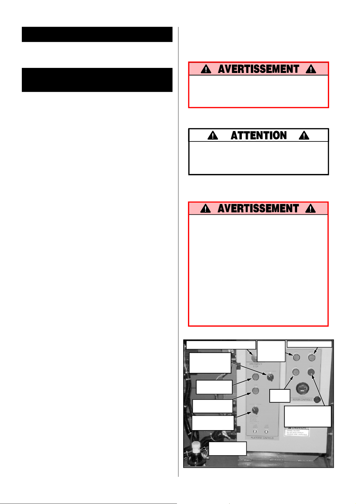
Emergency Stop Switch
Platform/Chassis
Switch
Raise Button
Lower Button
Fuel Selector Switch
Start
Button
Stop
Button
Throttle
Button
Choke/Glow
Plug Button
Tilt Sensor
Figure 1: Chassis, Left Side
3
Page 4

1. Unhook controller from front guardrail. Firmly
grasp controller hanger in such a manner that
the interlock lever can be depressed, while
performing the following checks from the
ground.
2. Turn controller key switch clockwise to ON.
Turn fully clockwise to start engine, releasing
the key once the engine starts.
Note: If the engine is cold, on dual fuel models,
depress and hold the choke button in while
starting the engine. On diesel models, depress
and hold the glow plug button for 6 seconds to
engage the glow plugs.
3. Position drive/lift switch to DRIVE position.
4. With the speed range switch first in HIGH
TORQUE and then again in HIGH SPEED
depress the interlock lever and slowly push the
control lever to FORWARD then REVERSE
positions to check for speed and directional
control. The farther you push or pull the
control lever the faster the machine will travel.
5. Push steering switch RIGHT then LEFT to
check for steering control.
6. Depress the interlock switch on the control
handle and position each outrigger switch to
the EXTEND position to deploy all four outriggers. Check the drive enable indicator light, it
should be off.
7. Fully retract all outriggers and check the drive
enable indicator, it should be on.
8. Rehook controller on front guardrail.
9. Turn the platform/chassis switch to CHAS-
SIS .
10.Push the throttle button in. Push chassis raise
button to elevate platform while pushing the
Steering Switch
Outrigger
Switches
Interlock Lever
Control Lever
Speed Range
Switch
tilt sensor (Figure 1) off of level. The platform
should only partially elevate and the tilt alarm
should sound. If the platform continues to
elevate and/or there is no alarm STOP and
remove the machine from service until it is
repaired.
11.Release the tilt sensor and fully elevate platform.
12.Visually inspect the elevating assembly, lift
cylinder, cables and hoses for damage or
erratic operation. Check for missing or loose
parts.
13.Lower the platform partially by pushing in on
the chassis lower switch, and check operation
of the audible lowering alarm.
14.Open the chassis emergency lowering valve
(Figure 3) to check for proper operation by
pulling and holding the knob out. Once the
platform is fully lowered, close the valve by
releasing the knob.
15.Turn the platform/chassis switch to PLAT-
FORM.
16.Mount the platform making sure the gate is
latched.
17.Position drive/lift switch to LIFT.
18.Depress the interlock lever and slowly push
the control lever to RAISE to raise the platform, fully actuate the control lever to check
proportional lift speed. Elevate the platform to
12 feet (3.7 m).
19.Depress the interlock switch on the control
handle and position any outrigger switch to
the EXTEND position, outriggers should be
disabled. If an outrigger extends during this
test STOP. Lower the platform and remove
the machine from service until it is repaired.
20.Slowly pull control lever to DOWN position to
lower platform. Check that lowering alarm
sounds.
21.Turn controller key switch to OFF, push the
emergency stop button and dismount the
platform.
22.Close and secure module covers.
Emergency
Stop Switch
Choke / Glow Plug Button
Lift/Drive
Switch
Figure 2: Controller
Drive Enable
Indicator
Key Switch
4
Page 5

Operation
Before operating work platform, ensure that the
pre-operation and safety inspection has been
completed, any deficiencies have been corrected
and the operator has been thoroughly trained on
this machine.
Travel With Platform Lowered
1. Verify chassis emergency stop switch is in the
ON position (turn counterclockwise), the drive
enable indicator is on, and that the platform/
chassis switch is on PLATFORM.
Note: Steering is not self-centering. Wheels
must be returned to the straight ahead position
by operating the steering switch.
Leveling the Platform (Outrigger
equipped machines only)
Never attempt to use the outriggers on soft
ground. The surface beneath them must be
suitable to support the weight of the machine.
Note: If the drive enable indicator is off, verify
that the platform is fully lowered and (if so
equipped) the outriggers are all fully retracted.
2. After mounting platform, close and latch gate.
Check that guardrails are in position and properly assembled with fasteners properly torqued.
3. Check that route is clear of persons, obstructions, holes and drop-offs and is capable of
supporting the wheel loads.
4. Check clearances above, below and to the
sides of the platform.
5. Pull controller emergency stop button out to
ON position.
6. Turn controller key switch fully clockwise to start
engine, releasing the key once the engine starts.
Note: If the engine is cold, on dual fuel models,
depress and hold the choke button in while
starting the engine. On diesel models, depress
and hold the glow plug button for 6 seconds to
engage the glow plugs.
7. Set the drive/lift speed range switch to HIGH
TORQUE.
8. Grasp the control lever so the interlock lever is
depressed (releasing the interlock lever cuts
power to controller). Slowly push or pull the
control lever to FORWARD or REVERSE to
travel in the desired direction. The farther you
push or pull the control lever from center the
faster the machine will travel.
9. While moving, push the drive/lift speed range
switch to HIGH SPEED for travel on level
surfaces or to HIGH TORQUE for climbing
grades or traveling in confined areas.
1. Look around the machine, make sure that
there is nothing obstructing the outriggers, and
that the surface beneath them is suitable to
support the weight of the machine.
2. Depress the interlock lever on the control
handle and operate the outrigger switches to
extend each outrigger until it is making firm
contact with the ground.
3. While observing the bubble level on the front
guardrail (fig. 3), extend the outrigger opposite
the position of the bubble until the platform is
level. For example: if the bubble is to the front
and left in the orbit, extend the rear right
outrigger. Continue to adjust until the bubble is
centered in the small circle indicating that the
platform is level.
4. Outriggers must be in firm contact with the
supporting surface, observe each outrigger to
verify.
To retract the outriggers:
1. Fully lower the platform.
2. Position each outrigger switch to RETRACT.
Observe the outriggers to ensure that they are
fully retracted. The drive enable indicator
light will not come on until all four outriggers
are fully retracted.
Steering
1. Push the steering switch RIGHT or LEFT to
turn the wheels. Observe the tires while maneuvering to insure proper direction.
Figure 3: Platform Orbit Level
5
Page 6

Raising and Lowering the Platform
1. Position the drive/lift switch to LIFT. Position
the outrigger on/off switch to OFF.
2. While holding the control lever so the interlock
lever is depressed, push the control lever
slowly to UP to raise the platform. Pushing the
control lever farther increases the lift speed.
3. When the work task is completed, position the
drive/lift switch to LIFT and lower the platform by pulling back on the control lever until
the platform is fully lowered.
Travel with Work Platform Elevated
Travel with platform elevated ONLY on firm and
level surfaces with outriggers fully retracted.
Note: The work platform will travel at reduced
speed when in the elevated position, and then
only when the front axle is parallel with the
rear axle, and (if so equipped) all four
outriggers are fully retracted. Drive is disabled
above 8m (26ft).
1. Check that the route is clear of persons, obstructions, holes and drop-offs, is level and
capable of supporting the wheel loads.
2. Check clearances above, below and to the
sides of platform.
3. Position the drive/lift switch to the DRIVE
position.
4. Push the control lever to FORWARD or RE-
VERSE for the desired direction of travel.
If the machine quits driving and the tilt alarm
sounds, immediately lower the platform and
move the machine to a level location before reelevating the platform.
2. Once the platform is fully lowered, release the
knob to close the valve.
Switching Fuels (Dual Fuel Only)
1. With engine running turn the fuel selector
switch (Figure 1) to the center position.
2. After the engine has quit running select the
appropriate fuel supply.
3. Restart the engine.
After Use Each Day
1. Ensure that the platform is fully lowered.
2. Park the machine on level ground, preferably
under cover, secure against vandals, children
or unauthorized operation.
3. Turn the key switch to OFF and remove the
key to prevent unauthorized operation.
Parking Brake Release (Figure 5)
Perform the following only when the machine
will not operate under its own power and it is
necessary to move the machine or when winching
onto a trailer to transport.
1. Close the needle valve by turning the knob
clockwise.
2. Pump the brake release pump until the parking brakes release and the wheels can be
turned.
3. The machine will now roll when pushed or
pulled.
4. Be sure to open the needle valve and verify
that the parking brakes have engaged before
the machine is operated.
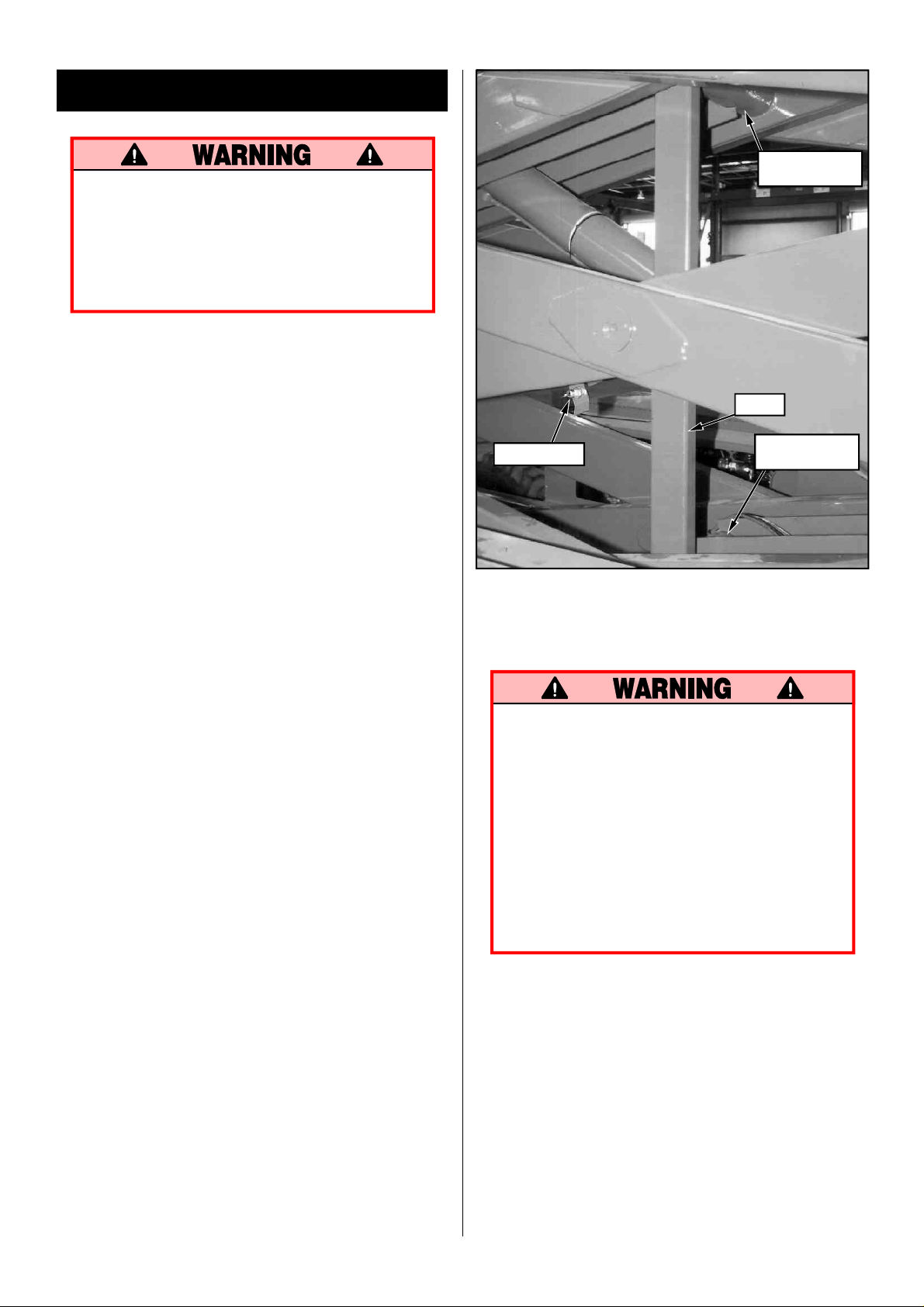
Emergency Lowering
The emergency lowering valve is located at the
front of the machine at the base of the scissor
assembly, (Figure 4).
1. Open the emergency lowering valve by pulling
on the knob and holding it.
Figure 4: Emergency Lowering Valve Knob
Never operate work platform with the
parking brakes released. Serious injury or
damage could result.
Pump
Needle
Valve
Figure 5: Parking Brake Release Pump
6
Page 7

Fold Down Guardrails
This procedure is only for passing through doorways. Guardrails must be returned to proper
position before using the machine.
Fold Down Procedure (Figure 6)
4. Raise front guardrail, aligning holes and install
bolts, washers and nuts. Tighten securely.
5. Hang controller from front guardrail.
6. Before operating work platform check that all
fasteners are in place and properly torqued.
Note: When performing the following procedures retain all fasteners.
1. Place controller on platform.
2. Starting at the front of the platform, remove
nuts, bolts and washers from the top of the
front guardrail. Fold the front guardrail down
onto the platform.
3. Close and latch the gate.
4. Remove nuts, bolts and washers from the top
of the rear guardrail. Fold the rear guardrail
down onto the platform being careful to keep
gate latched at all times.
5. Remove nuts, bolts and washers from the top
of the side guardrails and from the slideout
deck midrail. Lift up and fold one side guardrail in so it rests on the deck. Repeat with other
side guardrails.
Erection Procedure
1. Raise side guardrails making sure each is
pushed down to secure the guardrail in the
vertical position.
2. Install bolts, washers and nuts between the
side guardrails, tighten securely.
3. Raise rear guardrail assembly, aligning holes
and install bolts, washers and nuts. Tighten
securely.
Before operating machine, guardrails must
be securely fastened in their proper position.
Transporting Work Platform
By Crane
1. Secure straps to chassis tie down/lifting lugs
only (Figure 7).
By Truck
1. Maneuver the work platform into transport
position and chock wheels.
2. Secure the work platform to the transport
vehicle with chains or straps of adequate load
capacity attached to the chassis tie down/lifting
lugs (Figure 7).
Overtightening of chains or straps through
tie down lugs may result in damage to
work platform.
Figure 6: Fold Down Guardrails
Figure 7: Transporting Work Platform
7
Page 8
Maintenance
Never perform service on the work platform in the elevating assembly area while
platform is elevated without first blocking
the elevating assembly.
DO NOT stand in elevating assembly area
while deploying or storing brace.
Blocking Elevating Assembly (Figure 8)
Installation
Upper Scissor
Center Pivot
1. Park the work platform on firm level ground.
2. Verify platform emergency stop switch is ON.
3. Turn platform/chassis switch to CHASSIS.
4. Start the engine using the chassis controls.
5. Push the throttle button in, the button will stay
in and the engine speed will increase. Using the
raise button, elevate platform until the scissors
brace can be rotated to the vertical position.
6. From the left side of the machine, disengage
the locking pin securing the brace. Rotate the
scissor brace counterclockwise until it is vertical
and between the two scissor center pivots.
7. Push lower button and gradually lower platform until brace is supporting the platform.
8. Disengage throttle by pushing throttle button
in again, the button will retract and the engine
will come to idle speed.
Removal
1. Using chassis controls, gradually raise platform
until the scissors brace clears the two scissor
center pivots.
2. Rotate scissors brace clockwise until the locking
pin engages.
3. Push lower button to completely lower platform.
4. Make sure the throttle button is disengaged and
platform/chassis switch is on PLATFORM.
Brace
Locking Pin
Figure 8: Blocking Elevating Assembly
Lower Scissor
Center Pivot
Battery Maintenance
Hazard of explosive gas mixture. Keep
sparks, flame and smoking materials away
from batteries.
Always wear safety glasses when working
with batteries.
Battery fluid is highly corrosive. Rinse
away any spilled fluid thoroughly with
clean water.
Always replace batteries with UpRight
batteries or manufacturer approved replacements weighing 62 lbs. each.
Check battery fluid level daily, especially if work
platform is being used in a warm, dry climate.
If electrolyte level is lower than 3/8 in. (10 mm)
above plates add distilled water only. DO NOT
use tap water with high mineral content it will
shorten battery life.
Keep terminals and tops of batteries clean.
Refer to the Service Manual to extend battery life
and for complete service instructions.
8
Page 9

Routine Service
Use the following table as a guide for routine
maintenance. Inspection and maintenance shall
be performed by personnel who are trained and
familiar with mechanical and electrical procedures. Refer to the Service Manual for complete
service instructions.
Please copy this page and use the Routine Service
Table as a checklist when inspecting a machine for
service.
Routine Service Table
Routine Service Table Key
Interval
Daily=each shift (every day) or every eight hours
30d=every month (30 days) or every 50 hours
3m=every 3 months or 125 hours
6m=every 6 months or 250 hours
1y=every year or 500 hours
2y=every 2 years or 1000 hours
Y=Yes/Acceptable
N=No/Not Acceptable
R=Repaired/Acceptable
COMPONENT INSPECTION OR SERVICES INTERVAL Y N R
Engine Oil Check level and condition Daily
Engine Fuel Check fuel level Daily
System Check for leaks Daily
Engine Check electrolyte level Daily
Battery Check specific gravity 30
System Clean exterior 6
Engine Check coolant level (with engine cold) Daily
Coolant Replace coolant 3
Hydraulic Check oil level Daily
Oil Change filter 6
Hydraulic Check for leaks Daily
System Check hose connections 30
Emergency Open the emergency lowering Daily
Hydraulic valve and check for
System serviceability
Controller Check switch operation Daily
Control Check the exterior of the cable Daily
Cable for pinching, binding or wear
Platform Check fasteners for proper torque Daily
Deck and Check welds for cracks Daily
Rails Check condition of deck Daily
Tires Check for damage Daily
Hydraulic Wipe clean 30
Pump Check for leaks at mating surfaces 30
Drive Motors
Steering Check hardware & fittings 6
System for proper torque
Check for leaks Daily
Change oil & filter (Dual Fuel) 30
Change oil & filter (Diesel) 100
Replace fuel filter 6
Check air cleaner Daily
Check battery cable condition Daily
Clean terminals 6
Drain and replace oil 2
Check hoses for exterior wear 30
Check air pressure (50psi) Daily
Check lug nuts (torque to 90 ft. lbs. [123 Nm]) 30
Check for hose fitting leaks Daily
Check mounting bolts for proper torque 30
Check for operation and leaks Daily
Oil all pivot points 30
Check steering cylinder for leaks & 30
mounting bolts for proper torque
D
HOURS
M
D
M
M
M
M
Y
D
D
D
D
D
D
M
D
D
COMPONENT INSPECTION OR SERVICES INTERVAL Y N R
Elevating Inspect for structural cracks Daily
Assembly Check pivot points for wear 30
Check pivot pin mounting bolts 30
for proper torque
Check scissor arms for bending 6
Grease scissor pins 30
Chassis Check hoses for pinch or Daily
rubbing points
Check component mounting 6
for proper torque
Check welds for cracks Daily
Lift Check the cylinder rod for wear 30
Cylinder Check pivot pin mounting bolts 30
for proper torque
Check seals for leaks 30
Inspect pivot points for wear 30
Check fittings for proper torque 30
Axle Check the cylinder rod for wear 30
Cylinder Check mounting pin pivot bolts 30
for proper torque
Check seals for leaks 30
Inspect pivot points for wear 30
Check fittings for proper torque 30
Entire Check for and repair Daily
Unit collision damage
Check fasteners for proper torque 3
Check for corrosion-remove 6
and repaint
Lubricate 30
Labels Check for peeling, missing, or unreadable Daily
labels & replace
D
D
M
D
M
D
D
D
D
D
D
D
D
D
D
M
M
D
Service Report
Date: _______________
Owner: ___________________________________
Model No:_____________ Serial No: __________
Serviced By: _______________________________
Service Interval:____________________________
9
Page 10

Specifications*
ITEM
Platform Size (Inside Toeboards)
Standard
w/ Extension
Max. Platform Capacity
Standard
w/ Extension
on Extension
Max. No. of occupants
Standard
on Extension
Height
Working Height
Max. Platform Height
Min. Platform Height
Dimensions
Weight, Standard
w/ Extension
Overall Width
Overall Height
Overall Length, Standard
Driveable Height
Surface Speed
Platform Lowered
Platform Raised
System Voltage
Hydraulic Tank Capacity
Maximum Hydraulic System
Pressure
Hydraulic Fluid
Normal Use (>32 °F [0 °C])
Low Temp. Use
(-10 to 32 °F [-23 to 0 °C])
Lift System
Lift Speed
Platform Leveling
Power Source
Drive Control
Control System
Horizontal Drive
Tires
Parking Brakes
Turning Radius
Maximum Gradeability
Wheel Base
Guardrails
Toeboard
(inside)
143.38 in. x 70 in. [3.64 m x 1.78 m]
179.38 in. x 68 in. [4.56 m x 1.73 m]
2000 lbs. [907kg]
2000 lbs. [907 kg]
500 lbs. [227 kg]
8 people
2 people
37 ft. [11.28 m]
31 ft. [9.45 m]
56.25 in. [1.43 m]
2WD: 9,220 lbs. [4,182 kg] 4WD: 9,580 lbs. [4,345 kg]
2WD: 9,650 lbs. [4,377 kg] 4WD: 10,010 lbs. [4,540 kg]
90 in. [2.29 m]
99.75 in. [2.53 m]
160.5 in. [4.08 m]
31 ft. [9.45 m]
0 to 3.1 mph [0 to 5.0 km/h]
0 to 0.3 mph [0 to .48 km/h]
12 Volt DC
28.3 Gallons [107.13 l]
3000 psi [206.8 bar]
ISO #46
5W-20 Motor Oil
One Single Stage Lift Cylinder
Raise, 40 sec./Lower, 60 sec.
8.5o (12in. [.3m]) Side/Side, 6o (12in. [.3m]) Fore/Aft
Diesel or Gasoline 20 HP Kubota, 3 Cylinder,
Water Cooled Engine
Proportional
Joystick Controller with Interlock Lever and
Thumb Rocker Steering; Speed & Function
Selector Switches and Emergency Stop Button
2WD: 2 Wheel, Hyd. Motors 4WD: 4 Wheel, Hyd. Motors
10-16.5 NHS 8 Ply, 50psi [3.4 bar]
Two, Spring Applied, Hydraulic Release, Multiple Disc
48 in. [1.22 m]
2WD: 30% [16.7º] 4WD: 35% [19.3º]
115.75 in. [2.94 m]
43.5 in. [1.1 m] high, Fold Down with Gate
6 in. [152 mm] High
* Specifications subject to change without notice.
Refer to Service Manual for complete parts and service information.
LX31
143.38 in. x 70 in. [3.64 m x 1.78 m]
179.38 in. x 68 in. [4.56 m x 1.73 m]
1,500 lbs. [680kg]
1,500 lbs. [680kg]
500 lbs. [227 kg]
6 people
2 people
47 ft. [14.33 m]
40 ft. 6 in. [12.34 m]
65.25 in. [1.66 m]
2WD: 10,560 lbs. [4,790 kg] 4WD: 10,920 lbs. [4,953 kg]
2WD: 10,990 lbs. [4,985 kg] 4WD: 11,350 lbs. [5,148 kg]
90 in. [2.29 m]
108.75 in. [2.76 m]
160.5 in. [4.08 m]
40 ft. 6 in. [12.34 m]
0 to 3.1 mph [0 to 5.0 km/h]
0 to 0.3 mph [0 to .48 km/h]
12 Volt DC
28.3 Gallons [107.13 l]
3000 psi [206.8 bar]
ISO #46
5W-20 Motor Oil
One Single Stage Lift Cylinder
Raise, 45 sec./Lower, 65 sec.
8.5o (12in. [.3m]) Side/Side, 6o (12in. [.3m]) Fore/Aft
Diesel or Gasoline 20 HP Kubota, 3 Cylinder,
Water Cooled Engine
Proportional
Joystick Controller with Interlock Lever and
Thumb Rocker Steering; Speed & Function
Selector Switches and Emergency Stop Button
2WD: 2 Wheel, Hyd. Motors 4WD: 4 Wheel, Hyd. Motors
10-16.5 NHS 8 Ply, 50psi [3.4 bar]
Two, Spring Applied, Hydraulic Release, Multiple Disc
48 in. [1.22 m]
2WD: 30% [16.7º] 4WD: 35% [19.3º]
115.75 in. [2.94 m]
43.5 in. [1.1 m] high, Fold Down with Gate
6 in. [152 mm] High
LX41
10
Page 11

Version française
RÈGLES DE SÉCURITÉ
NE JAMAIS
moins de 3 mètres de lignes
d’énergie électrique.
MACHINE N’EST PAS ISOLÉE.
NE JAMAIS
dangers, tels que des trous, des dénivellations, des bosses et des débris.
NE JAMAIS
moyen de toutes les pièces de fixation serrées au bon couple.
REFERMER
NE PAS
NE JAMAIS
NE JAMAIS
REGARDER
ou autre obstacle aux alentours.
RÉPARTIR
voir la fiche technique à la page couverture arrière.
NE JAMAIS
composant le numéro sans frais inscrit à la page couverture arrière.)
NE JAMAIS
VÉRIFIER
commande sont en bon état, que toutes les pièces de fixation sont bien serrées, y compris les boulons de fixation des
roues, que le circuit hydraulique ne présente aucune fuite et que tous les fils électriques sont bien branchés.
NE JAMAI
NE JAMAIS
avoir d’abord bloqué ce dernier au moyen d’un étai.
NE JAMAIS
rechargement, les batteries dégagent de l’hydrogène gazeux hautement explosif.
APRÈS AVOIR UTILISÉ
la retirer afin de prévenir l’utilisation de la plate-forme par toute personne non autorisée.
NE JAMAIS
sans le consentement du fabricant.
utiliser la machine à
CETTE
utiliser la machine sans avoir d’abord vérifié si la surface de la zone de travail ne présente pas de
utiliser la machine sans que tous les garde-corps soient bien montés en place et fixés solidement au
et verrouiller le portillon après être monté sur la plate-forme.
s’approcher des stabilisateurs au moment d’élever ou d’abaisser la plate-forme.
dresser d’échelle ni d’échafaudage sur la plate-forme.
agrandir la surface de la plate-forme, ni y fixer une charge qui la déborde.
en haut, en bas et tout autour de la machine afin de s’assurer qu’il n’y a aucun conducteur électrique
également toutes les charges sur la plate-forme. Pour connaître la capacité maximale de cette dernière,
utiliser une machine endommagée. (Si la machine est endommagée, communiquer avec UpRight en
modifier les éléments assurant le fonctionnement de la machine, ni les dispositifs de sécurité.
la machine de fond en comble en s’assurant que toutes les soudures et tous les câbles électriques ou de
S descendre par le dispositif d’élévation lorsque la plate-forme est élevée.
effectuer des travaux d’entretien dans la zone du dispositif d’élévation d’une plate-forme élevée sans
recharger la batterie d’accumulateurs près d’une flamme ou d’une source d’étincelles : au moment du
la plate-forme élévatrice, tourner la clé de l’interrupteur à la position d’arrêt « OFF », puis
remplacer quelque élément ou quelque pièce que ce soit par autre chose qu’une pièce d’origine UpRight,
NE JAMAIS
que la machine ne soit sur une surface
horizontale solide et, lorsque la plateforme est élevée, NE déplacer la
machine QUE sur une telle surface.
élever la plate-forme sans
NE JAMAIS
se mettre debout sur les rampes du
garde-corps de la plate-forme.
s’asseoir, monter ou
11
Page 12
Introduction
Ce manuel se rapporte à tous les modèles de plateformes élévatrices de travail appartenant à la série LX.
On veillera à le garder sur la machine en tout temps.
Nota : En cas d’alimentation au gaz de pétrole
liquéfié (G.P.L.), utiliser un G.P.L. propre et sans eau
qui, préférablement, provient d’un grand réservoir.
Pour faire le plein, voir les consignes fournies sur le
support du bloc de puissance.
Vérification préliminaire de
sécurité
Lire d’abord attentivement toutes les règles de
sécurité, les étiquettes et le mode d’emploi, en
s’assurant de les comprendre et de s’y conformer.
Chaque jour avant d’utiliser la machine, exécuter les
tâches suivantes :
1. Ouvrir les modules, puis vérifier que les éléments
sont en bon état, qu’il n’y a aucune fuite d’huile et
qu’aucune pièce ne manque.
2. La plate-forme baissée, vérifier le niveau d’huile
hydraulique à l’aide de la jauge à fenêtre du
réservoir. Ajouter au besoin de l’huile ISO no 46.
3. Vérifier le niveau d’électrolyte de la batterie. (Voir
« Entretien de la batterie », à la page 17.)
4. Vérifier le niveau d’huile du moteur et le niveau de
carburant.
5. S’assurer que les garde-corps sont en place, la plateforme coulissante de rallonge est goupillée et les
pièces de fixation sont toutes bien serrées.
6. Vérifier si la pression des pneus est de 3,4 bars
(50 lb/po2).
7. Vérifier la plate-forme élévatrice de fond en comble
en s’assurant que les soudures et toutes les pièces
— comme les éléments porteurs, les câbles
électriques, les tuyaux flexibles et les pneus — sont
en bon état, que toutes les pièces sont fixées
solidement en place et qu’aucune d’elles ne
manque, qu’il n’y a aucune fuite d’huile et que tous
les fils électriques sont bien branchés.
8. Si besoin est, déplacer la machine à un endroit
dépourvu d’obstacles afin de pouvoir élever la
plate-forme à la hauteur maximale.
9. Aux tableaux de commandes du châssis et de la
plate-forme, tirer sur le bouton d’arrêt d’urgence
pour le régler à la position « ON » (figures 1 et 2).
10. Régler le sélecteur de châssis/plate-forme à la
position « PLATFORM » (figure 1).
11. Modèle à deux combustibles : régler le sélecteur de
combustible à la position désirée. Au moment de
changer de combustible, purger le circuit
d’alimentation en réglant le sélecteur à la position
centrale. Pour alimenter la machine au propane,
ouvrir le robinet d’alimentation du réservoir.
Si une odeur de propane est perceptible, fermer
immédiatement le robinet du réservoir. Avant
de l’ouvrir à nouveau, repérer la fuite et la
réparer.
12. Pendant que le moteur est froid, vérifier le niveau
du liquide de refroidissement.
NE PAS vérifier le niveau du liquide de
refroidissement lorsque le moteur ou le
radiateur sont chauds. Une fois chaud, ce
liquide peut causer de graves brûlures.
Essai de fonctionnement des
éléments
S’ÉLOIGNER de la plate-forme de travail au
moment d’effectuer les essais décrits ci-après.
Avant d’utiliser la plate-forme de travail,
vérifier si la surface de la zone de travail ne
présente pas de dangers à l’utilisateur, tels que
des trous, des dénivellations, des bosses et des
débris.
REGARDER en haut, en bas et tout autour de
la machine afin de s’assurer qu’il n’y a aucun
conducteur électrique ou autre obstacle aux
alentours.
En effectuant les essais, protéger le câble du
pupitre de commande contre tout dommage
éventuel.
Bouton d’arrêt d’urgence
Sélecteur de
châssis/plate-
forme
Bouton
d’élévation
Bouton
d’abaissement
Sélecteur de
combustible
Bouton
de
démarrage
Bouton
d’arrêt
Bouton des gaz
Bouton
d’étrangleur/de
préchauffage
12
Détecteur
d’inclinaison
Figure 1 : Châssis, côté gauche
Page 13

1. Décrocher le boîtier de commande du garde-corps
avant. Saisir fermement le crochet de suspension
du boîtier de commande, de façon à pouvoir
actionner le levier d’enclenchement solidaire au
moment d’effectuer les essais au sol décrits ci-après.
2. Régler l’interrupteur à clé du boîtier de commande
à la position « ON ». Pour ce faire, tourner la clé à
fond dans le sens des aiguilles d’une montre pour
lancer le moteur, et la relâcher dès que le moteur se
met en marche.
Nota : Marches à suivre lorsque le moteur est froid.
Dans le cas d’un modèle à deux combustibles, rentrer
le bouton d’étrangleur et le maintenir durant le
démarrage. Dans le cas d’un modèle diesel, rentrer le
bouton de préchauffage et le maintenir durant six
secondes pour enclencher les bougies de
préchauffage.
3. Régler le sélecteur de mode de fonctionnement à la
position de déplacement « DRIVE ».
4. Le sélecteur de plage de vitesses réglé d’abord à la
position de couple élevé « HIGH TORQUE », puis
à la position de grande vitesse « HIGH SPEED »,
vérifier les commandes de vitesse et de direction.
Pour ce faire, appuyer sur le levier d’enclenchement
solidaire et déplacer progressivement le levier de
commande à la position de marche avant
« FORWARD », puis à la position de marche arrière
« REVERSE ». La vitesse de déplacement de la
machine augmentera à mesure que le levier de
commande s’éloigne de la position neutre.
5. Vérifier la commande de direction en déplaçant le
bouton de commande de direction d’abord vers la
DROITE, puis vers la GAUCHE.
6. Appuyer sur le levier d’enclenchement solidaire du
levier de commande, puis régler chacun des
boutons de commande de stabilisateur à la position
de déploiement « EXTEND », afin de déployer tous
les quatre stabilisateurs. S’assurer que le témoin du
mode de déplacement s’éteint.
7. Rentrer à fond tous les stabilisateurs et s’assurer
que le témoin du mode de déplacement s’allume.
8. Raccrocher le boîtier de commande au garde-corps
avant.
9. Régler le sélecteur de châssis/plate-forme à la
position « CHASSIS ».
Bouton de commande
de direction
Bouton de
commande de
stabilisateur
Levier d'enclenchement
solidaire
Levier de
commande
Sélecteur de
plage de vitesses
Témoin du mode
de déplacement
10. Rentrer le bouton des gaz. Appuyer sur le bouton
d’élévation situé sur le tableau de commande du
châssis, puis déplacer le détecteur d’inclinaison
(figure 1) de sa position de nivelage en le poussant.
La plate-forme devrait arrêter avant d’atteindre sa
hauteur maximale, et l’alarme du détecteur
d’inclinaison devrait sonner. Si la plate-forme
continue à s’élever ou que l’alarme ne sonne pas,
ARRÊTER la machine et la faire réparer avant de
l’utiliser à nouveau.
11. Relâcher le détecteur d’inclinaison, et élever la
plate-forme à la hauteur maximale.
12. Vérifier le bon état et le bon fonctionnement des
éléments suivants : le dispositif d’élévation, le
vérin, les câbles et les tuyaux flexibles. S’assurer
que les pièces sont fixées solidement en place et
qu’aucune d’elles ne manque.
13. Abaisser partiellement la plate-forme au moyen du
bouton d’abaissement situé sur le tableau de
commande du châssis, puis vérifier le
fonctionnement de l’alarme sonore d’abaissement.
14. Au châssis, vérifier le bon fonctionnement de la
soupape d’abaissement de secours (figure 4). Pour
ce faire, l’ouvrir en tirant sur sa tirette de
commande et la maintenir dans la position ouverte.
Une fois la plate-forme abaissée à fond, fermer la
soupape en relâchant la tirette.
15. Régler le sélecteur de châssis/plate-forme à la
position « PLATFORM ».
16. Monter sur la plate-forme et fermer le portillon au
loquet.
17. Régler le sélecteur de mode de fonctionnement à la
position d’élévation « LIFT ».
18. Appuyer sur le levier d’enclenchement solidaire et
déplacer progressivement le levier de commande à
la position d’élévation « RAISE » pour élever la
plate-forme. Ce faisant, actionner le levier sur toute
sa course afin de vérifier la vitesse d’élévation
proportionnelle. Élever la plate-forme jusqu’à une
hauteur de 3,7 mètres (12 pi).
19. Appuyer sur le levier d’enclenchement solidaire du
levier de commande, puis régler un des boutons de
commande de stabilisateur à la position de sortie
« EXTEND » : aucun stabilisateur ne doit se
déployer. Si l’un des stabilisateurs se déploie,
INTERROMPRE l’essai et abaisser la plate-forme.
Faire réparer la machine avant de l’utiliser à
nouveau.
20. Déplacer progressivement le levier de commande à
la position d’abaissement « DOWN », pour abaisser
la plate-forme. S’assurer que l’alarme
d’abaissement sonne.
21. Tourner la clé du boîtier de commande à la position
« OFF », rentrer le bouton d’arrêt d’urgence et
descendre de la plate-forme.
22. Fermer les modules en s’assurant que les couvercles
sont fixés solidement en place.
Bouton d'arret
d'urgence
Bouton d'étrangleur/de préchauffage
Figure 2 : Boîtier de commande
Selecteur de
mode de
fonctionnement
Interrupteur
à clé
13
Page 14

Mode d’emploi
Avant d’utiliser la plate-forme élévatrice de travail,
effectuer la vérification préliminaire de sécurité et
réparer toute défectuosité relevée. S’assurer également
que l’opérateur a reçu une formation pratique qui lui a
permis de bien connaître l’utilisation de la machine.
GAUCHE, selon le cas. En manoeuvrant, observer
le mouvement des pneus afin d’assurer qu’ils
s’orientent dans la bonne direction.
Nota : La direction n’est pas de type à centrage
automatique. Pour ramener les roues à la position
droite, il faut donc actionner le bouton de commande
de direction.
Déplacement — plate-forme abaissée
1. Au tableau de commande du châssis, régler le
bouton d’arrêt d’urgence à la position « ON » en le
tournant dans le sens inverse des aiguilles d’une
montre. S’assurer que le témoin du mode de
déplacement s’allume, et régler le sélecteur de
châssis/plate-forme à la position « PLATFORM ».
Nota : Si le témoin du mode de déplacement ne
s’allume pas, s’assurer que la plate-forme est abaissée
à fond et que tous les stabilisateurs sont
complètement rentrés (dans le cas d’une machine qui
en est équipée).
2. Monter sur la plate-forme et fermer le portillon au
loquet. S’assurer que les garde-corps sont bien
montés en place et que leurs pièces de fixation sont
toutes bien serrées.
3. Vérifier la voie de passage en s’assurant qu’elle est
libre de personnes, d’obstacles, de trous et de
dénivellations, et qu’elle est capable de supporter
les charges des roues.
4. Vérifier l’espace disponible de chaque côté de la
plate-forme, y compris au-dessus et au-dessous de
celle-ci.
5. Tirer sur le bouton d’urgence d’arrêt pour le régler
à la position « ON ».
6. Au boîtier de commande, tourner la clé à fond dans
le sens des aiguilles d’une montre pour lancer le
moteur, et la relâcher dès que le moteur se met en
marche.
Nota : Marches à suivre lorsque le moteur est froid.
Dans le cas d’un modèle à deux combustibles, rentrer
le bouton d’étrangleur et le maintenir durant le
démarrage. Dans le cas d’un modèle diesel, rentrer le
bouton de préchauffage et le maintenir durant six
secondes pour enclencher les bougies de
préchauffage.
7. Régler le sélecteur de plage de vitesses à la position
de couple élevé « HIGH TORQUE ».
8. Saisir le levier de commande de façon à appuyer
sur le levier d’enclenchement solidaire. (Le fait de
relâcher ce dernier coupe l’alimentation du boîtier
de commande.) Déplacer progressivement le levier
de commande à la position de marche avant
« FORWARD » ou à celle de marche arrière
« REVERSE », selon le cas. La vitesse de
déplacement de la machine augmentera à mesure
que le levier de commande s’éloigne de la position
neutre.
9. Pendant que la machine se déplace, régler le
sélecteur de plage de vitesses à la position de
grande vitesse « HIGH SPEED » pour rouler sur
une surface horizontale, ou à la position de couple
élevé « HIGH TORQUE » pour monter une pente
ou rouler dans un espace restreint.
Nivelage de la plate-forme (machines
équipées de stabilisateurs seulement)
Ne jamais appuyer les stabilisateurs sur un sol
mou. Ces derniers doivent s’appuyer contre
une surface suffisamment solide pour soutenir
le poids de la machine.
1. Regarder autour de la machine pour s’assurer
qu’aucun obstacle ne gênera le déploiement des
stabilisateurs et vérifier si la surface d’appui est
suffisamment solide pour soutenir le poids de la
machine.
2. Appuyer sur le levier d’enclenchement solidaire du
levier de commande, puis régler les boutons de
commande de stabilisateur de façon à déployer tous
les stabilisateurs jusqu’à ce que chacun s’appuie
fermement contre le sol.
3. Tout en observant le niveau à bulle situé sur le
garde-corps avant (figure 3), déployer davantage le
stabilisateur situé du côté opposé à la position de la
bulle, jusqu’à ce que la plate-forme soit à
l’horizontale. Par exemple : si la bulle se trouve à
l’avant et vers la gauche du globe, déployer le
stabilisateur arrière droit. Continuer à effectuer de
tels réglages jusqu’à ce que la bulle soit bien centrée
dans le petit repère circulaire, ce qui indique que la
plate-forme est de niveau.
4. S’assurer que chaque stabilisateur s’appuie
fermement contre le sol.
Escamotage des stabilisateurs
1. Abaisser la plate-forme à fond.
2. Régler chacun des boutons de commande de
stabilisateur à la position d’escamotage
« RETRACT ». S’assurer que tous les stabilisateurs
sont complètement escamotés. Le témoin du mode
de déplacement ne s’allumera pas tant que tous les
quatre stabilisateurs ne sont pas complètement
escamotés.
Commande de direction
1. Pour orienter les roues, déplacer le bouton de
commande de direction vers la DROITE ou vers la
Figure 3 : Niveau globulaire de la plate-forme
14
Page 15

Élévation et abaissement de la
plate-forme
1. Régler le sélecteur de mode de fonctionnement à la
position d’élévation « LIFT ». Régler l’interrupteur
du circuit des stabilisateurs à « OFF ».
2. Saisir le levier de commande de façon à appuyer
sur le levier d’enclenchement solidaire, et le
déplacer progressivement à la position d’élévation
« UP » pour faire lever la plate-forme. Pour
augmenter la vitesse d’élévation, éloigner
davantage le levier de commande de la position
neutre.
3. Une fois le travail terminé, régler le sélecteur de
mode de fonctionnement à la position d’élévation
« LIFT » et abaisser la plate-forme en déplaçant le
levier de commande vers soi, jusqu’à ce que la
plate-forme s’abaisse à fond.
Déplacement — plate-forme élevée
Lorsque la plate-forme est élevée, NE déplacer la
machine QUE sur des surfaces horizontales solides et
que si les stabilisateurs sont rentrés à fond.
Nota : La plate-forme élevée, la machine se déplace à
vitesse réduite, et ce seulement à condition que les
essieux avant et arrière soient parallèles et que les
quatre stabilisateurs soient rentrés à fond (dans le cas
d’une machine qui en est équipée). Le mécanisme
assurant le déplacement de la machine ne fonctionne
pas lorsque la plate-forme est élevée à une hauteur
supérieure à huit mètres (26 pieds).
1. Vérifier la voie de passage en s’assurant qu’elle est
libre de personnes, d’obstacles, de trous et de
dénivellations, et qu’elle est capable de supporter
les charges des roues.
2. Vérifier l’espace disponible de chaque côté de la
plate-forme, y compris au-dessus et au-dessous de
celle-ci.
3. Régler le sélecteur de mode de fonctionnement à la
position de déplacement « DRIVE ».
4. Déplacer le levier de commande à la position de
marche avant « FORWARD » ou à celle de marche
arrière « REVERSE », selon le cas.
Si la machine arrête de rouler et que l’alarme du
détecteur d’inclinaison sonne, abaisser
immédiatement la plate-forme et déplacer la machine
sur une surface horizontale avant d’élever à nouveau
la plate-forme.
Abaissement d’urgence
La soupape d’abaissement de secours se trouve à
l’avant de la machine, à la base du support articulé de
la plate-forme (figure 4).
1. Ouvrir la soupape d’abaissement de secours en
tirant sur sa tirette et en maintenant celle-ci dans la
position sortie.
2. Une fois la plate-forme abaissée complètement,
relâcher la tirette pour fermer la soupape.
Changement de combustible (modèles
à deux combustibles seulement)
1. Le moteur en marche, régler le sélecteur de
combustible (figure 1) à la position centrale.
2. Une fois le moteur arrêté, sélectionner le
combustible désiré.
3. Remettre le moteur en marche.
Après utilisation, tous les jours
1. Abaisser à fond la plate-forme.
2. Stationner la machine sur une surface plane,
préférablement à l’abri des vandales, des enfants et
de toute personne qui pourrait éventuellement s’en
servir sans autorisation.
3. Tourner la clé de l’interrupteur à la position d’arrêt
« OFF », puis la retirer afin de prévenir l’utilisation
de la plate-forme par toute personne non autorisée.
Desserrage des freins de
stationnement (figure 5)
On ne doit exécuter cette marche à suivre que lorsqu’il
faut déplacer la machine et qu’elle ne réagit pas aux
commandes, ou pour la charger sur une remorque à
l’aide d’un treuil.
1. Fermer le robinet à pointeau en tournant sa poignée
dans le sens des aiguilles d’une montre.
2. Actionner la pompe de desserrage du frein, jusqu’à
ce que les freins de stationnement se desserrent et
que les roues puissent tourner.
3. La machine peut maintenant être déplacée en la
poussant ou en la tirant.
4. Avant d’utiliser à nouveau la machine, ouvrir le
robinet à pointeau et s’assurer que les freins de
stationnement sont bloqués.
Pompe
Robinet à
pointeau
Figure 4 : Tirette de la soupape d’abaissement de secours Figure 5 : Pompe de desserrage des freins
de stationnement
15
Page 16

Ne jamais utiliser la plate-forme à moins que
les freins de stationnement ne soient bloqués.
Sinon l’on risque de provoquer des dommages
ou des blessures graves.
Garde-corps rabattables
On ne doit exécuter cette marche à suivre que pour
faire passer la machine par une entrée de porte. Avant
d’utiliser à nouveau la machine, il faut remettre les
garde-corps dans leur position normale.
Mise à plat des garde-corps (figure 6)
Nota : Récupérer toutes les pièces de fixation afin de
pouvoir les utiliser à nouveau.
1. Placer le boîtier de commande sur la plate-forme.
2. Depuis l’avant de la plate-forme, déposer les
écrous, les boulons et les rondelles situés à
l’extrémité supérieure du garde-corps avant, puis
abaisser ce dernier sur la plate-forme.
3. Fermer le portillon au loquet.
4. Déposer les écrous, les boulons et les rondelles
situés à l’extrémité supérieure du garde-corps
arrière, puis abaisser ce dernier sur la plate-forme.
Veiller à ce que le portillon reste verrouillé.
5. Déposer les écrous, les boulons et les rondelles
situés à l’extrémité supérieure des garde-corps
latéraux, ainsi que ceux de la rampe intermédiaire
de la plate-forme coulissante de rallonge. Soulever
un des garde-corps et le replier sur la plate-forme.
Replier les autres de la même façon.
Redressement
1. Lever les garde-corps latéraux dans leur position
verticale et les fixer solidement en place en les
poussant à fond.
2. Poser les boulons, les rondelles et les écrous reliant
les garde-corps latéraux, et bien les serrer.
3. Lever le garde-corps arrière et aligner les trous de
fixation. Poser les boulons, les rondelles et les
écrous, puis bien les serrer.
4. Lever le garde-corps avant et aligner les trous de
fixation. Poser les boulons, les rondelles et les
écrous, puis bien les serrer.
5. Accrocher le boîtier de commande au garde-corps
avant.
6. Avant d’utiliser la plate-forme élévatrice, s’assurer
que toutes les pièces de fixation sont en place et
qu’elles sont bien serrées.
Avant d’utiliser à nouveau la machine,
s’assurer que les garde-corps sont bel et bien en
place et qu’ils sont fixés solidement.
Transport de la plate-forme
élévatrice
Déplacement par grue
1. Attacher les sangles au châssis, seulement aux
brides de levage/arrimage (figure 7).
Par camion
1. Mettre la plate-forme élévatrice en position de
transport en la manoeuvrant, puis caler les roues.
2. Arrimer la plate-forme élévatrice sur le véhicule de
transport au moyen de chaînes ou de sangles assez
fortes pour la retenir. Attacher ces dernières aux
brides de levage/arrimage du châssis (figure 7).
Le fait de trop serrer les chaînes ou les sangles
peut endommager la plate-forme élévatrice.
Figure 6 : Garde-corps rabattables
16
Vue de l’arrière
Brides de levage/arrimage
Figure 7 : Transport de la plate-forme élévatrice
Vue de l’avant
Page 17

Entretien
NE JAMAIS effectuer des travaux d’entretien
dans la zone du dispositif d’élévation d’une
plate-forme élevée sans avoir d’abord bloqué
ce dernier au moyen d’un étai.
NE PAS se tenir dans la zone du dispositif
d’élévation au moment de déployer ou de
ranger l’étai.
Étayage du dispositif d’élévation
(figure 8)
Axe d’articulation
central supérieur
du support
articulé
Déploiement de l'étai
1. Stationner la plate-forme élévatrice sur une surface
horizontale solide.
2. Régler le bouton d’arrêt d’urgence de la plate-forme
à la position « ON ».
3. Régler le sélecteur de châssis/plate-forme à la
position « CHASSIS ».
4. Mettre le moteur en marche à partir du tableau de
commandes du châssis.
5. Rentrer le bouton des gaz : celui-ci restera dans la
position rentrée et la vitesse de rotation du moteur
augmentera. Au moyen du bouton d’élévation,
élever suffisamment la plate-forme pour pouvoir
mettre l’étai du support articulé dans la position
verticale en le faisant pivoter.
6. Depuis le côté gauche de la machine, libérer la
goupille de blocage retenant l’étai. Faire pivoter
l’étai dans le sens inverse des aiguilles d’une
montre, jusqu’à ce qu’il se trouve dans la position
verticale, entre les deux axes de rotation centraux
du support articulé.
7. Appuyer sur le bouton d’abaissement et abaisser
progressivement la plate-forme, jusqu’à ce que le
poids de la plate-forme repose sur l’étai.
8. Réduire les gaz en appuyant de nouveau sur le
bouton des gaz : celui-ci sortira et le moteur se
mettra à tourner au ralenti.
Escamotage de l'étai
1. Au moyen des commandes du châssis, élever
progressivement la plate-forme, jusqu’à ce que l’étai
puisse passer entre les deux axes d’articulation
centraux du support articulé.
2. Faire pivoter l’étai dans le sens des aiguilles d’une
montre, jusqu’à ce que la goupille de blocage
s’engage dans le trou qui lui est destiné.
3. Appuyer sur le bouton d’abaissement pour abaisser
à fond la plate-forme.
4. S’assurer que le bouton des gaz est sorti, et régler le
sélecteur de châssis/plate-forme à la position
« PLATFORM ».
Étai
Goupille de
blocage
Figure 8 : Étayage du dispositif d’élévation
Axe d’articulation
central inférieur du
support articulé
Entretien de la batterie
Risque d’émanations gazeuses explosives.
Tenir la batterie à l’écart d’étincelles, de
flammes et de toute source de chaleur extrême.
Ne jamais manipuler la batterie sans porter de
lunettes de sécurité.
L’électrolyte est un liquide très corrosif.
Éliminer toute trace de liquide déversé de la
batterie en rinçant à grande eau claire.
Toujours remplacer la batterie par une batterie
UpRight ou de rechange homologuée par le
fabricant et pesant au moins 28 kg (62 lb).
Vérifier le niveau d’électrolyte tous les jours, surtout
lorsque le temps est sec et chaud.
Si l’électrolyte ne recouvre pas les plaques de batterie
d’au moins 10 mm (3/8 po), ajouter de l’eau distillée
seulement. NE PAS utiliser de l’eau de robinet à haute
teneur en minéraux, sinon la vie utile de la batterie sera
raccourcie.
Garder les bornes et le dessus de la batterie propres.
Le manuel d’entretien contient les marches à suivre
détaillées pour entretenir la batterie et lui assurer une
longue vie utile.
17
Page 18

Entretien courant
Le tableau ci-après sert de guide pour l’entretien
courant. Seules les personnes formées qui
connaissent les opérations mécaniques et électriques
doivent réaliser la vérification de contrôle et
l’entretien de la plate-forme élévatrice. Les consignes
d’entretien se trouvent dans le Manuel d’entretien.
Au moment de vérifier la machine, reproduire cette
page et utiliser le tableau qui s’y trouve comme liste de
vérification.
Tableau d’entretien courant
ÉLÉMENT VÉRIFICATION OU ENTRETIEN À EFFECTUER
Huile Vérifier le niveau et l’état Quot.
moteur Vérifier l’absence de fuites Quot.
Vidanger l’huile et changer de filtre 30j
(modèle à deux combustibles)
Vidanger l’huile et changer de filtre 100 hres
(modèle diesel)
Circuit Vérifier le niveau de carburant Quot.
carburant Vérifier l’absence de fuites Quot.
Remplacer le filtre à carburant 6m
Vérifier le filtre à air Quot.
Batterie Vérifier le niveau d’électrolyte Quot.
d'accuma- Vérifier le poids volumique 30j
lateurs Nettoyer l’extérieur 6m
Vérifier l’état du câble de batterie Quot.
Nettoyer les bornes 6m
Liquide Vérifier le niveau (le moteur froid) Quot.
de refroi- Remplacer le liquide de refroidissement 3m
dissement
Huile Vérifier le niveau Quot.
hydraulique Changer de filtre 6m
Remplacer l’huile hydraulique 2a
Circuit Vérifier l’absence de fuites Quot.
hydraulique Vérifier le raccordement des tuyaux flexibles 30j
Vérifier l’usure extérieure des tuyaux flexibles 30j
Circuit Ouvrir la soupape d’abaissement Quot.
hydraulique de secours et vérifier son bon
de secours fonctionnement
Boîtier de Vérifier le bon fonctionnement des boutons Quot.
commande de commande
Câble de Vérifier l’absence de toute trace de Quot.
commande pincement, de coincement ou d’usure
Plate-forme Vérifier le serrage des pièces de fixation Quot.
de travail et Vérifier le bon état des soudures Quot.
garde-corps Vérifier l’état de la plate-forme de travail Quot.
Pneus Vérifier le bon état Quot.
Vérifier la pression d’air (3,4 bars [50 lb/po2]) Quot.
Vérifier le serrage des écrous (123 N m [90 lbf-pi]) 30j
Pompe Bien essuyer 30j
hydraulique Vérifier l’absence de fuites aux surfaces de contact 30j
Vérifier l’absence de fuites aux raccordements Quot.
Vérifier le serrage des boulons de fixation 30j
Moteurs d'en- Vérifier le bon fonctionnement
traînement et l’absence de fuites Quot.
Commande Vérifier le serrage des pièces de fixation 6m
de direction et des raccords
Graisser tous les points d’articulation 30j
Vérifier le vérin de direction en s’assurant 30j
de l’absence de fuites et du bon serrage des
boulons de fixation
PÉRIODICITÉ
O N R
Légende du tableau
Périodicité
Quot. = chaque quart de travail (quotidiennement)
ou toutes les huit heures
30j = tous les mois (30 jours) ou toutes les
50 heures
3m = tous les 3 mois ou toutes les 125 heures
6m = tous les 6 mois ou toutes les 250 heures
1a = chaque année ou toutes les 500 heures
2a = tous les 2 ans ou toutes les 1 000 heures
O = oui/acceptable
N = non/inacceptable
R = réparé/acceptable
ÉLÉMENT VÉRIFICATION OU ENTRETIEN À EFFECTUER
Dispositif Vérifier l’absence de fissures Quot.
d’élévation Vérifier l’usure des pièces aux points 30j
d’articulation
Vérifier le serrage des boulons de fixation 30j
des axes d’articulation
Vérifier l’absence de toute torsion/tout 6m
gauchissement des bras du support articulé
Graisser les axes d’articulation 30j
Châssis Vérifier l’absence de toute trace de Quot.
pincement ou d’usure par frottement
Vérifier le serrage des pièces de fixation des 6m
éléments constitutifs
Vérifier le bon état des soudures Quot.
Vérin Vérifier l’usure de la tige de vérin 30j
d’élévation Vérifier le serrage des boulons de fixation des 30j
axes d’articulation
Vérifier l’absence de fuites aux joints 30j
Vérifier l’usure des pièces aux points 30j
d’articulation
Vérifier le serrage des raccordements 30j
Vérin Vérifier l’usure de la tige de vérin 30j
d’essieu Vérifier le serrage des boulons de fixation 30j
des axes d’articulation
Vérifier l’absence de fuites aux joints 30j
Vérifier l’usure des pièces aux points 30j
d’articulation
Vérifier le serrage des raccordements 30j
Ensemble Vérifier l’absence de tout signe d’endommage- Quot.
de la ment dû aux chocs; réparer au besoin
machine Vérifier le serrage des pièces de fixation 3m
Vérifier l’absence de toute trace de corrosion; 6m
décaper et peindre au besoin
Lubrifier 30j
Étiquettes Vérifier le bon état et la lisibilité des étiquettes Quot.
en s’assurant qu’aucune ne manque;
remplacer au besoin
PÉRIODICITÉ
Fiche d’entretien
Date :_________________
Propriétaire : __________________________________
No de modèle : _________ No de série : ___________
Nom du technicien :____________________________
Périodicité d’entretien : _________________________
O N R
18
Page 19

ÉLÉMENT
Dimensions de la plateforme
(intérieur de la plinthe
Normales
Avec plate-forme de rallonge
Capacité max. de la plate-forme
Normale
Avec plate-forme de rallonge
De la plate-forme de rallonge
Nombre max. de personnes
Normale
Sur la plate-forme de rallonge
Hauteur
Hauteur de travail
Hauteur max. de la plate-forme
Hauteur min. de la plate-forme
Dimensions
Poids normal
avec plate-forme de rallonge
Largeur hors tout
Hauteur hors tout
Longueur hors tout, normale
Hauteur max. au déplacement
Vitesse de déplacement
Plate-forme baissée
Plate-forme leveé
Tension du circuit électrique
Capacité du réservoir
hydraulique
Pression maximale du circuit
hydraulique
Liquide hydraulique
Utilisation, conditions
normales (>0 oC [32 oF])
Utilisation à basse température
(-23 à 0 oC [-10 à 32 oF])
Dispositif d’élévation
Vitesse d’élévation
Nivelage de la plate-forme
Moteur
Mécanisme d’entraînement
Système de commande
Traction
Pneus
Freins de stationnement
Rayon de virage
Pente gravissable max.
Empattement
Garde-corps
Plinthe
(intérieur)
)
Fiche technique*
LX31 LX41
3,64 m x 1,78 m (143,38 po x 70 po)
4,56 m x 1,73 m (179,38 po x 68 po)
907 kg (2 000 lb)
907 kg (2 000 lb)
227 kg (500 lb)
8 personnes
2 personnes
11,28 m (37 pi)
9,45 m (31 pi)
1,43 m (56,25 po)
Traction 2 roues : 4 182 kg (9 220 lb);
4 roues : 4 345 kg (9 580 lb)
Traction 2 roues : 4 377 kg (9 650 lb);
4 roues : 4 540 kg (10 010 lb)
2,29 m (90 po)
2,53 m (99,75 po)
4,08 m (160,5 po)
9,45 m (31 pi)
0 à 5,0 km/h (0 à 3,1 mi/h)
0 à 0,48 km/h (0 à 0,3 mi/h)
12 V c.c.
107,13 L (28,3 gal.)
206,8 bars (3 000 lb/po2)
ISO no 46
Huile moteur 5W-20
Un vérin d’élévation à un étage
Élévation : 40 s; abaissement : 60 s
Axe transversal : 8,5o (0,3 m [12 po]); axe
longitudinal : 6o (0,3 m [12 po])
Moteur Kubota diesel ou à essence de 20 ch à 3
cylindres, refroidi au liquide
Régulation proportionnelle
Manche à balai muni d’un levier
d’enclenchement solidaire et d’un bouton de
commande de direction à bascule au pouce;
sélecteurs de vitesse et de mode de
fonctionnement; bouton d’arrêt d’urgence
Traction 2 roues : moteurs hydrauliques aux 2 roues;
traction 4 roues : moteurs hydrauliques aux 4 roues
8 plis NHS 10-16,5; 3,4 bars (50 lb/po2)
Deux, à ressort, desserrage hydraulique, disques multiples
1,22 m (48 po)
Traction 2 roues : 30 % (16,7o); 4 roues : 35 % (19,3o)
2,94 m (115,75 po)
1,1 m (43,5 po) de hauteur; à rabattement; portillon
152 mm (6 po) de hauteur
3,64 m x 1,78 m (143,38 po x 70 po)
4,56 m x 1,73 m (179,38 po x 68 po)
680 kg (1 500 lb)
680 kg (1 500 lb)
227 kg (500 lb)
6 personnes
2 personnes
14,33 m (47 pi)
12,34 m (40 pi, 6 po)
1,66 m (65,25 po)
Traction 2 roues : 4 790 kg (10 560 lb);
4 roues : 4 953 kg (10 920 lb)
Traction 2 roues : 4 985 kg (10 990 lb);
4 roues : 5 148 kg (11 350 lb)
2,29 m (90 po)
2,76 m (108,75 po)
4,08 m (160,5 po)
12,34 m (40 pi, 6 po)
0 à 5,0 km/h (0 à 3,1 mi/h)
0 à 0,48 km/h (0 à 0,3 mi/h)
12 V c.c.
107,13 L (28,3 gal.)
206,8 bars (3 000 lb/po2)
ISO no 46
Huile moteur 5W-20
Un vérin d’élévation à un étage
Élévation : 45 s; abaissement : 65 s
Axe transversal : 8,5o (0,3 m [12 po]); axe
longitudinal : 6o (0,3 m [12 po])
Moteur Kubota diesel ou à essence de 20 ch à 3
cylindres, refroidi au liquide
Régulation proportionnelle
Manche à balai muni d’un levier
d’enclenchement solidaire et d’un bouton de
commande de direction à bascule au pouce;
sélecteurs de vitesse et de mode de
fonctionnement; bouton d’arrêt d’urgence
Traction 2 roues : moteurs hydrauliques aux 2 roues;
traction 4 roues : moteurs hydrauliques aux 4 roues
8 plis NHS 10-16,5; 3,4 bars (50 lb/po2)
Deux, à ressort, desserrage hydraulique, disques multiples
1,22 m (48 po)
Traction 2 roues : 30 % (16,7o); 4 roues : 35 % (19,3o)
2,94 m (115,75 po)
1,1 m (43,5 po) de hauteur; à rabattement; portillon
152 mm (6 po) de hauteur
* Ces caractéristiques peuvent être changées sans préavis.
La liste des pièces et les consignes d’entretien détaillée se trouvent dans le manuel d’entretien.
19
Page 20

Nota:
20
Page 21

Deutschsprachiger Teil
SICHERHEITSREGELN
BEDIENEN
innerhalb von 3 Meter einer
Stromlinie.
NICHT ISOLIERT.
BEDIENEN
Löcher, Bodensenkungen, Schlaglöcher oder Schutt.
BEDIENEN
gut angezogen sind.
SCHLIEßEN
HALTEN
VERWENDEN
BRINGEN
vergrößern.
SCHAUEN
VERTEILEN
Wagenbühnenbeladung.
VERWENDEN
gebührenfreie Telefonnummer auf der Rückseite.)
ÄNDERN
INSPIZIEREN
hydraulischen Lecks, beschädigten Kontrollen oder Stromkabeln, sowie losen Drahtverbindungen.
KLETTERN
FÜHREN
den Hebemechanismus zu blockieren.
LADEN
strömen hochexplosives Wasserstoffgas aus.
NACH VERWENDUNG
abschalten und den Schlüssel abziehen.
ERSETZEN
ohne vorher die Zustimmung des Herstellers erhalten zu haben.
Kalifornien Antrag 65 - Vorsicht
Benzin- und Dieselmotoren vertreiben Abgase und einige der Komponenten sind nach Ansicht des Staates Kalifornien
mögliche Verursacher von Krebs, Geburtsschäden und anderen Fortpflanzungsschäden.
Sie die Maschine
DIESE MASCHINE IST
Sie die Maschine
Sie die Maschine
und sichern Sie das Gitter nach dem Betreten der Wagenbühne.
Sie alle Körperteile vom Stützgeländer fern, wenn Sie die Hebebühne erweitern oder einziehen.
Sie
NIE
Sie
NIE
überhängende Ladungen an der Wagenbühne an, versuchen Sie
Sie nach oben, unten und rundherum nach Hindernissen und Oberleitungen.
Sie alle Ladungen gleichmäßig auf der Wagenbühne. Siehe Angaben auf der Rückseite bzgl. maximaler
Sie
NIE
Sie
NIE
die Bedienungs- oder Sicherheitssysteme.
Sie die Maschine gründlich nach gebrochenen Schweißnähten, losen oder fehlenden Systemteilen,
Sie
NIE
an der Hebebühne herunter, wenn die Wagenbühne erhöht ist.
Sie
NIE
irgendwelche Reparaturen an der Maschine durch, während die Wagenbühne erhöht ist, ohne vorher
Sie die Batterie
Sie
NIE
irgendwelche Komponenten oder Teile mit Ersatzteilen, die nicht original UpRight Teile sind,
NIE
NIE
NIE
Leitern oder Gerüste auf der Wagenbühne.
beschädigte Ausrüstung. (Beziehen Sie sich auf UpRight bzgl. Anweisungen. Benutzen Sie die
NIE
in der Nähe von Funken oder offener Flamme auf; Batterien, die aufgeladen werden,
sichern Sie die Arbeitsbühne gegen unbefugte Verwendung, indem Sie den Schlüsselschalter
ERHÖHEN
und
während sie sich in erhöhtem Zustand
befindet, es sei denn sie befindet sich
auf einem festen, ebenen Untergrund.
, ohne vorher den Arbeitsbereich bezüglich Gefahrenstellen zu überprüfen, wie z.B.
, wenn nicht alle Schutzgeländer richtig aufgerichtet und alle Befestigungsriegeln
Sie die Wagenbühne
FAHREN
Sie die Maschine
NIE
NIE
SITZEN
Sie
die Mittelgestänge der
Wagenbühne.
NIE
, stehen oder erklettern
NIE
das Schutzgeländer oder
, die Wagenbühne zu
21
Page 22

Einleitung
Diese Bedienungsanleitung betrifft alle Modelle der
Arbeitsbühnen der LX Serie. Diese Bedienungsanleitung
muß zu allen Zeiten mit der Maschine zusammen
aufbewahrt werden.
Anmerkung: Wenn Sie flüssiges Benzin verwenden,
benutzen Sie sauberes, wasserfreies flüssiges Benzin,
am besten von einem Großvorratstank. Befolgen Sie
die Anweisungen, die sich an der
Kraftstoffmodulablage zum Auffüllen des Tanks
befinden.
Vor-Inbetriebnahme und
Sicherheitsinspektion
Lesen, verstehen und befolgen Sie diese
Sicherheitsregeln, den Aufschriften und
Bedienungsanweisungen genau, und führen Sie dann
die folgenden Schritte täglich vor jedem Gebrauch aus.
1. Öffnen Sie die Module und prüfen Sie nach Schaden,
Öllecks oder fehlenden Teilen.
2. Überprüfen Sie den Hydraulikölstand am
Sichtmesser, der sich am Hydrauliktank befindet;
dazu muß die Wagenbühne ganz gesenkt sein. Füllen
Sie ISO #46 Hydrauliköl nach, wenn nötig.
3. Überprüfen Sie den Flüssigkeitsstand der Batterie
(Siehe Batteriewartung, Seite 26).
4. Überprüfen Sie den Stand von Motoröl und Benzin.
5. Prüfen Sie, ob alle Schutzgeländer richtig angebracht
sind, daß die Gleitdeckverlängerung mit dem Splint
und den Riegeln gesichert und gut festgezogen ist.
6. Prüfen Sie den Reifendruck; 3,4 bar (50 psi).
7. Überprüfen Sie die gesamte Arbeitsbühne genau auf
Schaden, wie z.B. gebrochene Schweißnähte oder
Strukturteile, lose oder fehlende Teile, Öllecks,
beschädigte Kabel oder Schläuche, sowie lose
Kontakte und Reifenschäden.
8. Bringen Sie die Maschine unter Umständen in einen
ungehinderten Bereich, um volle Aufrichtung
möglich zu machen.
9. Schalten Sie den Fahrwerk- und WagenbühneNotschalter auf ON (Ein) (Abb. 1 & 2), indem Sie die
Knöpfe herausziehen.
10. Versichern Sie sich, daß sich der Wagenbühne/
Fahrwerkschalter in der PLATFORM (Wagenbühne)
Position befindet (Abb.1).
11. Bei Doppelbenzin Modellen: schalten Sie die
Doppelbenzinwahl in die gewünschte Position.
Schalten Sie auf Mittelposition, um das System zu
reinigen, wenn Sie Benzin umschalten. Wenn die
Maschine mit Propangas betrieben wird, öffnen Sie
das Zulaufventil am Tank.
Wenn Sie Propangas riechen, schließen Sie das
Zulaufventil am Tank sofort, bis Sie das Leck
gefunden und repariert haben.
12. Während der Motor kalt ist, überprüfen Sie den
Kühlflüssigkeitsstand des Motors.
Prüfen Sie die Kühlflüssigkeit nicht, wenn der
Motor oder der Kühler heiß ist, heiße
Kühlflüssigkeit kann ernsthafte Verbrennungen
verursachen.
Inspektion der Systemfunktionen
HALTEN Sie sich von der Arbeitsbühne FERN,
während die folgenden Kontrollen
vorgenommen werden.
Bevor Sie die Arbeitsbühne in Betrieb nehmen,
untersuchen Sie den Arbeitsbereich bzgl.
Oberflächengefahren, wie z.B. Löcher,
Bodensenkungen, Schlaglöcher oder Schutt.
Überprüfen Sie in ALLEN Richtungen, auch
oberhalb der Arbeitsbühne, nach Hindernissen
und elektrischen Leitern.
Schützen Sie das Kabel des Kontrollpult vor
möglichem Schaden, während Sie die Kontrollen
vornehmen.
Notschalter
Wagenbühne /
Fahrwerk Schalter
Startknopf
Drosselknopf
Hebeknopf
Senkknopf
Benzinwahlschalter
22
Stopknopf
Choke-/
Vorglühknopf
Kippsensor
Abbildung 1: Fahrwerk, linke Seite
Page 23

1. Haken Sie den Controller vom vorderen Schutzgeländer
ab. Halten Sie den Controlleraufhänger so, daß der
Sperrhebel gedrückt werden kann, während die
folgenden Kontrollen vom Boden aus vorgenommen
werden.
2. Drehen Sie den Controller Schlüsselschalter im
Uhrzeigersinn auf ON (Ein). Drehen Sie ganz im
Uhrzeigersinn, um den Motor anzulassen, lassen Sie
den Schlüssel locker, sobald der Motor angesprungen
ist.
Anmerkung: Bei Doppelbenzin Modellen, wenn der
Motor kalt ist, drücken und halten Sie den ChokeKnopf innen, während Sie den Motor starten. Bei
Diesel Modellen, drücken und halten Sie den
Vorglühknopf 6 Sekunden lang, um die Glühkerzen zu
entzünden.
3. Schalten Sie den Fahr/ Hebeschalter auf die DRIVE
(Fahr) Position.
4. Drücken Sie den Sperrhebel, wobei der
Geschwindigkeitsschalter zuerst auf HIGH
TORQUE (Hohe Umdrehung) und dann auf HIGH
SPEED (Hohe Geschwindigkeit) gestellt wird.
Schieben Sie dann langsam den Kontrollhebel auf
FORWARD (Vorwärts), dann REVERSE (Rückwärts),
um die Geschwindigkeits- und Richtungskontrollen
zu prüfen. Je weiter Sie den Kontrollhebel schieben
oder ziehen, desto schneller wird sich die Maschine
bewegen.
5. Schieben Sie den Steuerungsschalter auf RIGHT
(Rechts), dann auf LEFT (Links), um die
Steuerungskontrolle zu prüfen.
6. Drücken Sie den Sperrhebel am Kontrollhebel und
bringen Sie alle Stützgestängeschalter in die
AUSFALT Postition, um alle vier Stützgestänge
auszufalten. Überprüfen Sie das Fahrindikationslicht,
es sollte ausgeschaltet sein.
7. Falten Sie alle Stützgestänge ganz aus und
überprüfen Sie den Fahrindikator, er sollte
eingeschaltet sein.
8. Haken Sie den Controller wieder am vorderen
Schutzgeländer ein.
9. Drehen Sie den Wagenbühne/ Fahrwerkschalter auf
CHASSIS (Fahrwerk).
Steuerungsschalter
Stützgestänge-
schalter
Sperrhebel
Kontrollhebel
Geschwindigkeits-
schalter
10. Schieben Sie den Drosselknopf ein. Drücken Sie den
Fahrwerk-Hebeknopf, um die Wagenbühne zu heben,
während Sie gleichzeitig den Kippsensor von der
Ebene weg schieben (Abb.1). Die Wagenbühne soll
sich nur zum Teil heben und der Kippalarm sollte
ausgelöst sein. Wenn sich die Wagenbühne weiter
hebt und/ oder der Alarm nicht ausgelöst wird,
STOPPEN Sie und entfernen Sie die Maschine vom
Dienst, bis sie repariert wird.
11. Lösen Sie den Kippsensor und heben Sie die
Wagenbühne ganz.
12. Überprüfen Sie die Hebebühne, den Hebezylinder, die
Kabel und Schläuche visuell auf Schaden oder
unberechenbaren Betrieb. Prüfen Sie nach fehlenden
oder losen Teilen.
13. Senken Sie die Wagenbühne zum Teil, indem Sie den
Fahrwerk-Senkschalter schieben, und überprüfen Sie
den Betrieb des hörbaren Senkalarms.
14. Öffnen Sie das Fahrwerk-Notsenkventil (Abb.3), um
durch das Schieben und Ziehen des Knopfs richtige
Betriebsfähigkeit sicherzustellen. Wenn die
Wagenbühne ganz gesenkt ist, schließen Sie das
Ventil, indem Sie den Knopf lösen.
15. Drehen Sie den Wagenbühne/ Fahrwerkschalter auf
PLATFORM (Wagenbühne).
16. Bringen Sie die Wagenbühne an und versichern Sie
sich, daß das Gitter eingeschnappt ist.
17. Drehen Sie den Fahr/ Hebeschalter auf LIFT (Heben).
18. Schieben Sie den Sperrhebel und drücken Sie dann
den Kontrollhebel langsam auf RAISE (Heben), um
die Wagenbühne zu heben; betätigen Sie den
Kontrollhebel ganz, um die proportionale
Hebegeschwindigkeit zu prüfen. Heben Sie die
Hebebühne auf 3,7 m (12 Fuß).
19. Drücken Sie den Sperrhebel am Kontrollhebel und
bringen Sie jegliche Stützgestängeschalter in die
EXTEND (Ausfalt) Position, die Stützgestänge sollten
nicht operabel sein. Sollte sich ein Stützgestänge
während dieses Tests ausfalten, stoppen Sie sofort.
Senken Sie die Hebebühne und entfernen Sie die
Maschine vom Betrieb, bis sie repariert ist.
20. Ziehen Sie den Kontrollhebel langsam nach DOWN
(Unten), um die Wagenbühne zu senken. Versichern
Sie sich, daß der Senkalarm ausgelöst wird.
21. Drehen Sie den Controller Schlüsselschalter auf OFF
(Aus), drücken Sie den Notknopf und steigen Sie von
der Wagenbühne herab.
22. Schließen und sichern Sie die Modulabdeckungen.
Notschalter
Fahrschalter
Choke-/Vorglühknopf
Abbildung 2: Controller
Fahrindikator
Hebe/
Schlüsselschalter
23
Page 24

Bedienung
Bevor Sie die Arbeitsbühne in Betrieb nehmen, versichern
Sie sich, daß die Vor-Inbetriebnahme und
Sicherheitsinspektion abgeschlossen wurde, daß jegliche
Mängel repariert wurden, und daß der Bediener bestens
auf dieser Maschine eingearbeitet wurde.
Fahren mit der gesenkten
Wagenbühne
11. Versichern Sie sich, daß der Fahrwerk-Notschalter
auf die ON (Ein) Position gestellt ist, (ziehen Sie
entgegen dem Uhrzeigersinn), daß der Fahrindikator
eingeschaltet ist, und daß der Wagenbühne/
Fahrwerkschalter auf PLATFORM (Wagenbühne)
gestellt ist.
Anmerkung: Wenn der Fahrindikator ausgeschaltet ist,
versichern Sie sich, daß die Hebebühne ganz gesenkt
ist und die Stützgestänge vollständig eingezogen sind
(wenn so ausgestattet).
2. Nachdem Sie die Wagenbühne befestigt haben,
schließen Sie das Gitter und klinken Sie es ein.
Versichern Sie sich, daß die Schutzgeländer richtig
aufgestellt und zusammengesetzt sind, mit den
Befestigungsriegeln richtig festgezogen.
3. Überprüfen Sie, daß der Weg frei ist von Personen,
Hindernissen, Löchern und Bodensenkungen, und
daß der Weg die Radladung tragen kann.
4. Prüfen Sie die Freiräume oberhalb, unterhalb und
seitlich der Wagenbühne.
5. Ziehen Sie den Controller Notschaltknopf heraus, in
die ON (Ein) Position.
6. Drehen Sie den Controller Schlüsselschalter ganz im
Uhrzeigersinn, um den Motor anzulassen, und lassen
Sie den Schlüssel los, sobald der Motor läuft.
Anmerkung: Bei Doppelbenzin Modellen, wenn der
Motor kalt ist, drücken und halten Sie den ChokeKnopf innen, während Sie den Motor starten. Bei
Diesel Modellen, drücken und halten Sie den
Vorglühknopf 6 Sekunden lang, um die Glühkerzen zu
entzünden.
7. Schalten Sie den Fahr/
Hebegeschwindigkeitsschalter auf HIGH TORQUE
(Hohe Umdrehung).
8. Greifen Sie den Kontrollhebel, so daß der Sperrhebel
gedrückt wird (das Loslassen des Sperrschalters
schaltet den Strom zum Controller ab). Schieben Sie
den Kontrollhebel langsam auf FORWARD
(Vorwärts), oder REVERSE (Rückwärts), um in die
gewünschte Richtung zu fahren. Je weiter Sie den
Kontrollhebel schieben oder ziehen, desto schneller
wird sich die Maschine bewegen.
9. Während Sie fahren, schieben Sie den Fahr/
Hebegeschwindigkeitsschalter auf HIGH SPEED
(Hohe Geschwindigkeit), wenn Sie auf ebenen
Oberflächen fahren, oder auf HIGH TORQUE (Hohe
Umdrehung), wenn Sie einer Steigung begegnen, oder
in engen Bereichen manövrieren.
(Rechts) oder LEFT (Links), um die Räder zu drehen.
Beobachten Sie die Räder, während Sie manövrieren,
um sicherzugehen, daß sie die gewünschte Richtung
einhalten.
Anmerkung: Die Steuerung richtet sich nicht von selbst
aus. Die Räder müssen wieder in die geradeaus
Position gedreht werden, indem Sie den
Steuerungsschalter bedienen.
Ausrichten der Hebebühne (Nur für
Maschinen mit Stützgestängen)
Versuchen Sie nie, die Stützgestänge auf
weichem Untergrund zu benutzen. Der
Untergrund muß unbedingt geeignet sein, das
Gewicht dieser Maschine zu unterstützen.
1. Sehen Sie sich um und versichern Sie sich, daß den
Stützgestängen nichts im Weg steht, und daß der
Untergrund geeignet ist, das Gewicht der Maschine
zu unterstützen.
2. Drücken Sie den Sperrhebel am Kontrollhebel und
bedienen Sie die Stützgestängeschalter un jedes
Gestänge auszufalten, bis es im festen Kontakt mit
dem Boden steht.
3. Während Sie die Blase im Ausrichtegerät im Auge
behalten, falten Sie die Gestänge entgegen der
Blasenposition aus, bis die Wagenbühne ausgerichtet
ist und eben steht. Zum Beispiel: wenn die Blase
vorne und links im Orbit ist, dann falten Sie das
hintere rechte Gestänge aus. Richten Sie das Gestänge
aus, bis sich die Blase in der Mitte des kleinen Kreises
befindet, und somit anzeigt, daß die Wagenbühne
eben ausgerichtet ist.
4. Die Stützgestänge müssen in festem Kontakt mit der
stützenden Oberfläche stehen, prüfen Sie jedes
einzelne Gestänge, um sicherzugehen.
Einfalten der Stützgestänge:
1. Senken Sie die Wagenbühne komplett.
2. Bringen Sie jeden Gestängeschalter in die RETRACT
(Einfalt) Postition. Behalten Sie die Gestänge im
Auge, um sicherzugehen, daß sie vollständig
eingefaltet werden. Das Fahrindikatorslicht schaltet
sich nicht ein, bis alle vier Stützgestänge vollständig
eingefaltet sind.
Steuerung
1. Schieben Sie den Steuerungsschalter nach RIGHT
Abbildung 3: Wagenbühne Orbit Ausrichtungsgerät
24
Page 25

Heben und Senken der
Wagenbühne
1. Drehen Sie den Fahr/ Hebeschalter auf LIFT (Heben).
Bringen Sie den On/ Off (Ein/Aus) Schalter des
Stützgestänges auf OFF (Aus).
2. Während Sie den Kontrollhebel halten, so daß der
Sperrhebel gedrückt ist, schieben Sie den
Kontrollhebel langsam auf UP (Auf), um die
Wagenbühne zu heben. Wenn Sie den Kontrollhebel
weiter schieben, so steigert sich die
Hebegeschwindigkeit.
3. Wenn die Arbeitsaufgabe vollendet ist, drehen Sie
den Fahr/ Hebeschalter auf LIFT (Heben) und
senken Sie die Wagenbühne, indem Sie den
Kontrollhebel nach hinten ziehen, bis die
Wagenbühne vollständig gesenkt ist.
Fahren mit erhobener Arbeitsbühne
Fahren Sie mit der erhobenen Wagenbühne NUR auf
festen und ebenen Oberflächen, wobei die Stützgestänge
vollständig eingefaltet sein müssen.
Anmerkung: Die Arbeitsbühne fährt mit reduzierter
Geschwindigkeit, wenn sie sich in erhöhter Position
befindet, und dann auch nur, wenn die Vorderachse
mit der Hinterachse parallel ist, und, (wenn so
ausgestattet) müssen die vier Stützgestänge vollständig
eingefaltet sein. Über 8 m (26 Fuß) ist das Fahrwerk
nicht operabel.
1. Überprüfen Sie, daß der Weg frei ist von Personen,
Hindernissen, Löchern und Bodensenkungen, und
daß der Weg die Radladung tragen kann.
2. Prüfen Sie die Freiräume oberhalb, unterhalb und
seitlich der Wagenbühne.
3. Drehen Sie den Fahr/ Hebeschalter auf die DRIVE
(Fahr) Position.
4. Schieben Sie den Kontrollhebel auf FORWARD
(Vorwärts) oder REVERSE (Rückwärts), je nachdem,
welche Richtung Sie einschlagen wollen.
Wenn die Maschine aufhört zu fahren und der
Kippalarm tönt, senken Sie die Wagenbühne sofort und
fahren Sie die Maschine auf einen ebenen Untergrund,
bevor Sie die Wagenbühne erneut heben.
Notsenkung
2. Sobald die Wagenbühne vollständig gesenkt ist,
lassen Sie den Knopf los, um das Ventil zu schließen.
Benzinumschaltung (nur bei
Doppelbenzin)
1. Wenn der Motor läuft, drehen Sie den
Benzinwahlschalter (Abb.1) in die Mittelposition.
2. Nachdem der Motor aufgehört hat zu laufen, wählen
Sie die geeignete Benzinzufuhr.
3. Lassen Sie den Motor wieder an.
Nach täglichem Gebrauch
1. Versichern Sie sich, daß die Wagenbühne vollständig
gesenkt ist.
2. Parken Sie die Maschine auf ebenem Boden, am
besten unter Dach, sichern Sie gegen Vandale, Kinder
oder unbefugten Betrieb.
3. Drehen Sie den Schlüsselschalter auf OFF (Aus) und
entfernen Sie den Schlüssel, um unbefugten Betrieb
zu verhindern.
Lösen der Feststellbremse
(Abbildung 5)
Führen Sie folgendes nur dann aus, wenn die Maschine
nicht mit eigener Kraft läuft und es nötig ist, die
Maschine anderswo hin zu bringen, oder wenn Sie sie an
einen Trailer oder ein Transportfahrzeug ankuppeln
wollen.
11. Schließen Sie das Nadelventil, indem Sie den Knopf
im Uhrzeigersinn drehen.
2. Pumpen Sie die Bremslösepumpe, bis sich die
Feststellbremse löst und die Räder gedreht werden
können.
3. Die Maschine kann nun gerollt werden, wenn man
sie schiebt oder zieht.
4. Versichern Sie sich, daß das Nadelventil offen ist und
daß die Feststellbremsen gegriffen haben, bevor Sie
die Maschine bedienen.
Bedienen Sie die Arbeitsbühne nie, wenn die
Feststellbremsen gelöst sind. Ernsthafte
Verletzungen oder Schaden kann entstehen.
Das Notsenkventil befindet sich vorne auf der
Maschine, am Fuße des Scherenaufbaus, (Abb.4).
1. Öffnen Sie das Notsenkventil, indem Sie am Knopf
ziehen und halten.
Abbildung 4: Notsenkventilknopf Abbildung 5: Feststellbrems-Lösepumpe
Pumpe
Nadelventil
25
Page 26

Umklappen der
Schutzgeländer
Diese Verfahren ist nur für den Durchgang durch
Türrahmen. Die Schutzgeländer müssen in die aufrechte
Position zurück gebracht werden, bevor die Maschine in
Betrieb genommen wird.
Umklappverfahren (Abbildung 6)
Anmerkung: Wenn Sie die folgenden Schritte
vornehmen, behalten Sie bitte alle Riegel und
Aufhänger.
1. Stellen Sie den Controller auf die Wagenbühne.
2. Beginnen Sie auf der Vorderseite der Wagenbühne,
entfernen Sie Schraubenmuttern, Schrauben und
Unterlegscheiben von der Oberseite der vorderen
Schutzgeländer.
3. Schließen Sie das Gitter und klinken Sie es ein.
4. Entfernen Sie Schraubenmuttern, Schrauben und
Unterlegscheiben von der Oberseite der hinteren
Schutzgeländer. Klappen Sie das hintere
Schutzgeländer auf die Wagenbühne herunter, und
halten Sie das Gitter in der Zwischenzeit eingeklinkt.
5. Entfernen Sie Schraubenmuttern, Schrauben und
Unterlegscheiben von der Oberseite der seitlichen
Schutzgeländer und von Gleitdeck des
Mittelgeländers. Heben und klappen Sie eine Seite der
Schutzgeländer ein, so daß es auf dem Deck liegt.
Wiederholen Sie diese Schritte mit dem anderen
Seitengeländer.
Aufstellverfahren
1. Heben Sie die Seitengeländer und versichern Sie sich,
daß jedes nach unten geschoben ist, um das
Schutzgeländer in vertikaler Position zu sichern.
2. Installieren Sie Schrauben, Unterlegscheiben und
Schraubenmuttern zwischen den Seitengeländern,
ziehen Sie sie gut fest.
3. Heben Sie den hinteren Schutzgeländeraufbau,
richten Sie die Löcher aus und installieren Sie die
Schrauben, Unterlegscheiben und Schraubenmuttern.
Ziehen Sie sie gut fest.
4. Heben Sie das vordere Schutzgeländer, richten Sie die
Löcher aus und installieren Sie die Schrauben,
Unterlegscheiben und Schraubenmuttern. Ziehen Sie
sie gut fest.
5. Hängen Sie den Controller an das vordere
Schutzgeländer.
6. Bevor Sie die Arbeitsbühne in Betrieb nehmen,
überprüfen Sie, daß alle Feststellriegel richtig
angebracht und festgezogen sind.
Bevor Sie die Maschine in Betrieb nehmen
müssen die Schutzgeländer fest und in
richtiger Position angebracht sein.
Transport der Arbeitsbühne
Per Kran
1. Sichern Sie das Fahrwerk mit Befestigungsriemen
und nur an den Hub/ Feststellvorsprüngen (Abb.7).
Per LKW
1. Manövrieren Sie die Arbeitsbühne in die
Transportposition und keilen Sie die Reifen ein.
2. Sichern Sie die Arbeitsbühne am Transportfahrzeug
mit Ketten oder Riemen, die der Ladung entsprechen,
und die Sie am Fahrwerk an den Hebe/
Feststellvorsprüngen befestigen (Abb.7).
Abbildung 6: Umklappen der Schutzgeländer
Überstreckung der Ketten oder Riemen durch die
Hebe/ Feststellvorsprünge kann Schaden an der
Arbeitsbühne verursachen.
Rückansicht Vorderansicht
Hub/ Feststellvorsprünge
Abbildung 7: Transport der Arbeitsbühne
26
Page 27

Instandhaltung
Warten Sie die Arbeitsbühne nie im erhobenen
Aufbaubereich während die Wagenbühne
erhoben ist, ohne vorher den erhöhten Aufbau
abzusperren.
STEHEN Sie NICHT im erhöhten Aufbaubereich,
während Sie die Verstrebung einsetzen oder
verstauen.
Absperren des erhöhten Aufbaus
(Abbildung 8)
Installation
1. Parken Sie die Arbeitsbühne auf festem, ebenem
Untergrund.
2. Versichern Sie sich, daß der WagenbühnenNotschalter auf ON (Ein) gestellt ist.
3. Drehen Sie den Wagenbühne/ Fahrwerkschalter auf
CHASSIS (Fahrwerk).
4. Lassen Sie den Motor an, indem Sie die
Fahrwerkkontrollen verwenden.
5. Schieben Sie den Drosselknopf ein, der Knopf bleibt
eingeschoben, und die Motorengeschwindigkeit
steigt. Heben Sie die Wagenbühne, indem Sie den
Hebeknopf betätigen, bis die Scherenstrebe in die
vertikale Position gedreht werden kann.
6. Lösen Sie den Feststellriegel, der die Verstrebung hält,
von der linken Seite der Maschine aus. Drehen Sie die
Scherenstrebe entgegen dem Uhrzeigersinn, bis sie
vertikal zwischen den beiden Scherenmittelarmen
steht.
7. Drücken Sie den unteren Knopf und senken Sie die
Wagenbühne langsam, bis die Verstrebung die
Wagenbühne stützt.
8. Lösen Sie die Drosselung, indem Sie den
Drosselknopf wieder einschieben, der Knopf springt
dann zurück und der Motor läuft im Leerlauf.
Entfernung
1. Verwenden Sie die Fahrwerkkontrollen um die
Wagenbühne allmählich zu heben, bis die
Scherenstrebe an den beiden Scherenmittelarmen
vorbei gekommen ist.
2. Drehen Sie die Scherenstrebe im Uhrzeigersinn, bis
der Feststellriegel einrastet.
3. Drücken Sie den Senkknopf, um die Wagenbühne
ganz zu senken.
4. Versichern Sie sich, daß der Drosselknopf
ausgeschaltet ist und daß der Wagenbühne/
Fahrwerkschalter auf PLATFORM (Fahrwerk)
geschaltet ist.
Oberer
Scherenmittelarm
Strebe
Feststellriegel
Abbildung 8: Absperren des erhöhten Aufbaus
Unterer
Scherenmittelarm
Batteriewartung
Explosionsgefahr durch Gasmischung. Halten
Sie Funken, Flammen und rauchende
Materialien von der Batterie fern.
Tragen Sie immer eine Schutzbrille, wenn Sie mit
Batterien arbeiten.
Batterieflüssigkeit ist äußerst ätzend. Spülen Sie
jegliche verschüttete Flüssigkeit sofort mit klarem
Wasser ab.
Ersetzen Sie die Batterien immer mit einer
UpRight Batterien oder mit Batterien, die vom
Hersteller empfohlen werden; diese sollten
jeweils 28,2 kg (62 Pfund) wiegen.
Überprüfen Sie den Flüssigkeitsstand der Batterie täglich,
besonders wenn die Arbeitsbühne in warmem, trockenem
Klima benutzt wird.
Wenn der Elektrolytstand auf weniger als 10mm
(3/8 Zoll) über den Platten ist, fügen Sie nur destilliertes
Wasser zu. VERWENDEN Sie KEIN Leitungswasser,
welches einen hohen Mineralienanteil hat, dies würde
die Arbeitsdauer der Batterie verkürzen.
Halten Sie die Polklemmen und Oberseite der Batterie
sauber.
Für Hinweise auf Verlängerung der Arbeitsdauer der
Batterie und für Betriebsanweisungen wenden Sie sich
bitte an die Betriebsanleitung.
27
Page 28

Routine Wartung
Verwenden Sie die folgende Tabelle als Leitlinie für
Routine Wartungen. Inspektion und Wartung soll von
qualifizierten Personen, die mechanische und
elektrische Kenntnisse haben, durchgeführt werden.
Wenden Sie sich an die Betriebsanleitung für komplette
Betriebsanweisungen.
Bitte kopieren Sie diese Seite und verwenden Sie die
Routine Wartungstabelle als Checkliste, wenn Sie die
Maschine prüfen oder warten.
Routine Wartungstabelle
Schlüssel für die Aufstellung: Routine Wartung
Intervall
Täglich = jede Schicht (jeden Tag) oder alle acht
Stunden
30T = jeden Monat (30 Tage) oder alle 50 Stunden
3M = alle 3 Monate oder 125 Stunden
6M = alle 6 Monate oder 250 Stunden
1J = einmal pro Jahr oder 500 Stunden
2J = alle zwei Jahre oder 1000 Stunden
J = Ja/Akzeptabel
N = Nein/Nicht akzeptabel
R = Repariert/Akzeptabel
KOMPONENT INSPEKTION ODER WARTUNG INTERVALL J N R
Motorenöl Stand und Kondition prüfen Täglich
Motorkraft- Kraftstoffstand prüfen Täglich
stoffsystems Auf Lecks prüfen Täglich
Motorbatteriesystem
Motor- Kühlflüssigkeitsstand prüfen (Motor kalt) Täglich
flüssigkeit Kühlflüssigkeit wechseln 3M
Hydrauliköl Ölstand prüfen Täglich
Hydraulik- Auf Lecks prüfen Täglich
system Schlauchanschlüsse prüfen 30T
Hydraulisches
Notsystem
Controller Schalterbetrieb prüfen Täglich
Kontrollkabel Äußerlich auf Druck, Klemmen und Täglich
Deck und Riegel auf richtige Drehung prüfen Täglich
Gitter der Schweißung auf Brüche prüfen Täglich
Wagenbühne Kondition des Decks prüfen Täglich
Reifen Auf Schaden prüfen Täglich
Hydraulische Sauber wischen 30T
Pumpe An Anschlußflächen auf Lecks prüfen 30T
Treibmotoren Betrieb und auf Lecks prüfen Täglich
Steuerungs- Systemteile und Anschlüsse auf 6M
system richtige Drehung prüfen
Auf Lecks prüfen Täglich
Öl- und Filterwechsel (Doppelbenzin) 30T
Öl- und Filterwechsel (Diesel)
Kraftstoffilterwechsel 6M
Luftfilterprüfen Täglich
Prüfen des Elektrolytstands Täglich
Wichte prüfen 30T
Äußeren Rahmen reinigen 6M
Kondition der Batteriekabel prüfen Täglich
Polklemmen reinigen 6M
Filter wechseln 6M
Öl ablassen und ersetzen 2J
Schläuche auf äußerliche Abnutzung prüfen 30T
Notsenkventil öffnen und auf Täglich
Betriebsfähigkeit prüfen
Abnutzung prüfen
Luftdruck (50psi=3,4 bar) Täglich
Schraubenmuttern der Nase prüfen 30T
(Drehmoment auf 90 Fuß Pfund [123Nm])
Schlauchverbindung auf Lecks prüfen Täglich
Befestigungsschrauben auf richtige 30T
Drehung prüfen
Alle Lagerbockstellen ölen 30T
Steuerungszylinder auf Lecks & 30T
Befestigungsschrauben auf richtige
Drehung prüfen
100Stunden
KOMPONENT INSPEKTION ODER WARTUNG INTERVALL J N R
Hebeaufbau Auf Risse in der Struktur prüfen Täglich
Fahrwerk Schläuche auf Druck oder Reibstellen Täglich
Hebebühne Zylinder Pleuelstange auf Abnutzung 30T
Zylinder prüfen
Achsen- Zylinderstange auf Abnutzung prüfen 30T
zylinder Lagerbockbefestigungsbolzen auf 30T
Gesamt- Prüfen Sie auf Kollisionsschaden und Täglich
maschine reparieren Sie sofort
Klebeschilder
Lagerbockstellen auf Abnutzung prüfen 30T
Lagerbockbefestigungsbolzen auf 30T
richtige Drehung prüfen
Scherenarme auf Biegung prüfen 6M
Scherenbolzen schmieren 30T
prüfen
Komponentenbefestigungen auf richtige 6M
Drehung prüfen
Schweißstellen auf Brüche prüfen Täglich
Lagerbockbefestigungsbolzen auf 30T
richtige Drehung prüfen
Dichtungen auf Lecks prüfen 30T
Lagerbockstellen auf Abnutzung prüfen 30T
Verschraubung auf richtige Drehung 30T
prüfen
richtige Drehung prüfen
Dichtungen auf Lecks prüfen 30T
Lagerbockstellen auf Abnutzung prüfen 30T
Verschraubung auf richtige Drehung 30T
prüfen
Riegel auf richtige Drehung prüfen 3M
Prüfen Sie auf Rost-entfernen Sie 6M
diesen und streichen Sie neu
Schmieren 30T
Prüfen Sie auf abblätternde, fehlende Täglich
oder unlesbare Klebeschilder und
ersetzen Sie diese
Wartungsreport
Datum:__________________
Eigentümer: _____________
Modellnr.: _____________ Seriennr.: ______________
Gewartet von: __________________________________
Wartungsintervall: _____________________________
28
Page 29

Leistungsverzeichnis*
TEIL LX31 LX41
Wagenbühnengröße
(innerhalb Fußgeländer)
Standard 3,64 m x 1,78 m (143,38 Zoll x 70 Zoll) 3,64 m x 1,78 m (143,38 Zoll x 70 Zoll)
Standard mit Erweiterung 4,56 m x 1,73 m (179,38 Zoll x 68 Zoll) 4,56 m x 1,73 m (179,38 Zoll x 68 Zoll)
Max.Kapazität der Wagenbühne
Standard 907 kg (2000 Pfund) 680 kg (1500 Pfund)
mit Erweiterung 907 kg (2000 Pfund) 680 kg (1500 Pfund)
Erweiterung 227 kg (500 Pfund) 227 kg (500 Pfund)
Max.Anzahl an Personen
Standard 8 Personen 6 Personen
auf der Erweiterung 2 Personen 2 Personen
Höhe
Arbeitshöhe 11,28 m (37 Fuß) 14,33 m (47 Fuß)
Max.Wagenbühnenhöhe 9,45 m (31 Fuß) 12,34 m (40Fuß 6 Zoll)
Min.Wagenbühnenhöhe 1,43 m (56,25 Zoll) 1,66 m (65,25 Zoll)
Dimensionen
Gewicht, Standard 2 Radantrieb 4.182 kg (9220 Pfund) 2 Radantrieb 4.790 kg (10560 Pfund)
mit Erweiterung 2 Radantrieb 4.377 kg (9650 Pfund) 2 Radantrieb 4.985 kg (10990 Pfund)
Gesamtbreite
Gesamthöhe
Gesamtlänge, Standard 4,08 m (160,5 Zoll) 4,08 m (160,5 Zoll)
Fahrbare Höhe
Oberflächengeschwindigkeit
Wagenbühne gesenkt 0 bis 5,0 km/h (0 bis 3,1 mph) 0 bis 5,0 km/h (0 bis 3,1 mph)
Wagenbühne gehoben 0 bis 0,48 km/h (0 bis 0,3 mph) 0 bis 0,48 km/h (0 bis 0,3 mph)
Systemspannung
Hydraulik Tank Kapazität
Max. Hydraulik
System Druck
Hydraulik Flüssigkeit
Normal Verbrauch (>0°C] ISO #46 ISO #46
Niedrigtemperatur Verbrauch
[-23 bis 0°C] 5W-20 Motorenöl 5W-20 Motorenöl
Hebebühne System
Hebebühnen-
geschwindigkeit
Wagenbühnenausrichtung
Kraftstoffquelle
Fahrkontrolle
Kontrollsystem
Horizontalantrieb
Reifen
Feststellbremsen
Drehradius
Max. Steigfähigkeit
Radstand
Schutzgeländer
Fußgeländer
(innen) 1,22 m (48 Zoll) 1,22 m (48 Zoll)
4 Radantrieb 4.345 kg (9580 Pfund) 4 Radantrieb 4.953 kg (10920 Pfund)
4 Radantrieb 4.540 kg (10010 Pfund) 4 Radantrieb 5.148 kg (11350 Pfund)
2,29 m (90 Zoll) 2,29 m (90 Zoll)
2,53 m (99,75 Zoll) 2,76 m (108,75 Zoll)
9,45 m (31 Fuß) 12,34 m (40 Fuß 6 Zoll)
12 Volt DC 12 Volt DC
107,13 l (28,3 Gallonen) 107,13 l (28,3 Gallonen)
206,8 bar (3000 psi) 206,8 bar (3000 psi)
Ein einstufiger Hubzylinder Ein einstufiger Hubzylinder
Heben, 40 Sekunden Heben, 45 Sekunden
Senken, 60 Senken, 65 Sekunden
8,5 (12 Zoll [.3m]) Seite/Seite, 8,5 (12 Zoll [.3m]) Seite/Seite
6 (12 Zoll [.3m]) Vorn/Hinten 6 (12 Zoll [.3m]) Vorn/Hinten
Diesel oder Benzin Diesel oder Benzin
20 PS Kubota, 20 PS Kubota
3 Zylinder 3 Zylinder
Wassergekühlter Motor Wassergekühlter Motor
Proportional Proportional
Joystick Controller mit Joystick Controller mit
Sperrhebel und Daumen- Sperrhebel und Daumenrocker Steuerung; rocker Steuerung;
Geschwindigkeits & Geschwindigkeits &
Funktionswahlschalter, Funktionswahlschalter,
sowie Notschalter sowie Notschalter
2 Radantrieb: 2 Rad-, 2 Radantrieb: 2 Rad-,
Hydraulikmotoren Hydraulikmotoren
4 Radantrieb: 4 Rad-, 4 Radantrieb: 4 Rad-,
Hydraulikmotoren Hydraulikmotoren
10-16,5 NHS 8 PR, 10-16,5 NHS, 8 PR,
3,4 bar (50 psi) 3,4 bar (50 psi)
Zwei, Federbetrieben, Zwei, Federbetrieben,
Hydraulikrückzug, Hydraulikrückzug,
Mehrscheibenbremse Mehrscheibenbremse
2 Radantrieb: 30% [16,7o] 2 Radantrieb: 30% [16,7o]
4 Radantrieb: 35% [19,3o] 4 Radantrieb: 35% [19,3o]
2,94 m (115,75 Zoll) 2,94 m (115,75 Zoll)
1,1 m (43,5 Zoll) hoch, 1,1 m (43,5 Zoll) hoch,
Faltbar mit Gitter Faltbar mit Gitter
152 mm (6 Zoll) hoch 152 mm (6 Zoll) hoch
* Änderungen im Leistungsverzeichnis vorbehalten. Alle Bestimmungen von OSHA und ANSI
A92.3-1990 wurden eingehalten oder überstiegen. Wenden Sie sich an die Bedienungsanleitung
bzgl. kompletter Ersatzteil und Wartungsinformation.
29
Page 30

Anmerkung:
30
Page 31

Versión en español
REGLAS DE SEGURIDAD
JAMÁS
de 3 m (10 pies) de líneas de alta
tensión.
AISLADA.
JAMÁS
desniveles y escombros.
JAMÁS
torsión correcto.
ASEGURE
EVITE
JAMÁS
JAMÁS
MIRE
DISTRIBUYA
permitida para la plataforma.
JAMÁS
JAMÁS
REVISE
de las ruedas.
JAMÁS
JAMÁS
JAMÁS
altamente explosivo.
DESPUÉS DE USAR
JAMÁS
opere la máquina a menos
LA MÁQUINA NO ESTÁ
opere la máquina sin antes cerciorarse que el área de trabajo esté libre de peligros, tales como hoyos,
opere la máquina si las barandas no están adecuadamente en su lugar y con los tornillos con el par de
y use el pestillo de la puerta al subirse a la plataforma.
tocar con el cuerpo los estabilizadores cuando se extiendan o retracten.
use escaleras o andamios en la plataforma.
cuelgue cargas en los lados de la plataforma o incremente su tamaño.
hacia arriba, abajo y alrededores para detectar obstáculos aéreos y conductores eléctricos.
uniformemente todas las cargas sobre la plataforma. Vea en la contraportada la carga máxima
use equipo dañado. (Pida instrucciones a UpRight. Vea el número de llamado gratis en la contraportada).
altere los sistemas de operación y seguridad.
a fondo las soldaduras, quincallería, sistema hidráulico, cables de control, conexiones de alambres y pernos
use los brazos de la tijeras para bajarse de la plataforma elevada.
repare o mantenga la máquina con la plataforma elevada sin bloquear el mecanismo de tijeras.
cargue la batería donde hayan chispas o llamas. Las baterías en carga emiten hidrógeno gaseoso, que es
, retire la llave del interruptor de partida para evitar usos no autorizados.
use repuestos que no sean UpRight genuinos sin la autorización del fabricante.
JAMÁS
mueva la máquina con la
plataforma arriba a menos que
esté en una superficie horizontal
firme.
levante la plataforma o
NUNCA
pare en las barandas de la
plataforma.
se suba, se siente o se
31
Page 32

Introducción
Este Manual incluye todos los modelos de la serie LX
de Plataformas de trabajo y debe mantenerse en la
máquina todo el tiempo.
Nota: Si usa propano líquido, asegúrese que no
contenga agua, preferiblemente de un estanque a
granel. Cumpla las instrucciones de la mesa del
módulo de potencia para llenar el estanque.
Inspección de pre-
operación y de seguridad
Lea cuidadosamente, comprenda y cumpla todas las
reglas de seguridad, calcomanías e instrucciones de
operación antes de efectuar las operaciones
siguientes, todos los días antes de usarla:
1. Abra los módulos y verifique que no haya daños,
goteras de aceite o que falten componentes.
2. Verifique el nivel de aceite en el indicador del
estanque hidráulico con la plataforma totalmente
abajo. Agregue aceite ISO # 46 si es necesario.
3. Verifique que el nivel de electrólito sea correcto
(vea Mantenimiento de batería, pág. 35).
4. Verifique los niveles del aceite lubricante y de
combustible.
5. Verifique que las barandas estén en su lugar, la
extensión de la plataforma asegurada con el
pasador y todos los pernos y tornillos bien
apretados.
6. Verifique la presión de los neumáticos: 3,4 bar
(50 lb/plg2).
7. Cuidadosamente, asegúrese que la plataforma no
tiene soldaduras o componentes estructurales
dañados, partes sueltas o no existentes, goteras de
fluidos, cables o mangueras dañadas, conexiones
sueltas y neumáticos dañados.
8. Traslade la máquina a un área sin obstáculos para
elevarla al máximo, si es necesario.
9. Para conectar los interruptores de parada de
emergencia del chasis y de la plataforma tire los
botones correspondientes (fig. 1 y 2).
10. Verifique que el interruptor de la plataforma /
chasis está en PLATAFORMA (fig. 1).
11. Modelos a doble combustible: seleccione el
combustible colocando el selector en la posición
deseada. Colóquelo en el centro para purgar el
sistema al cambiar de combustible. Si la máquina
debe usar propano, abra la válvula del estanque.
Si huele propano, cierre la válvula del estanque
inmediatamente hasta que haya ubicado y
eliminado la fuga.
12. Verifique el nivel de refrigerante con el motor frío.
NO inspeccione el refrigerante con el motor o
radiador calientes. El refrigerante caliente
puede causar quemaduras graves.
Inspección de funciones del sistema
Párese lejos de la plataforma de trabajo cuando
ejecute los controles siguientes.
Antes de operar la máquina asegúrese que el
área de trabajo esté libre de peligros tales como
hoyos, desniveles y escombros.
Mire en todas direcciones, incluso sobrecabeza, para detectar obstáculos y conductores
eléctricos.
Proteja el cable de control de la consola contra
daños cuando ejecute las verificaciones.
Botón de
estrangulación
Interruptor parada de
emergencia
Conmutador
plataforma / chasis
Botón de levante
Botón de bajada
Conmutador
selector de
combustible
Botón de
arranque
Botón de
detención
de combustible
Botón de
estrangulación de
aire/bujía de
incandescencia
32
Sensor de inclinación
Figura 1: Chasis, lado izquierdo
Page 33

1. Desenganche el contralor de la baranda frontal.
Coja firmemente el colgador del contralor para
permitir presionar la palanca de enganche cuando
realice los controles siguientes, desde el piso.
2. Gire la llave del contralor hacia la derecha a
contacto, gire más para arrancar el motor. Suéltela
cuando el motor haya arrancado.
Nota: Si el motor está frío, en modelos a doble
combustible, presione y sostenga el botón
estrangulador al arrancar el motor. En modelos diesel,
presione y sostenga, durante 6 segundos, el botón de
la bujías de incandescencia para conectarlas.
3. Coloque el conmutador maneje/levante en la
posición de maneje.
4. Con el selector de velocidades, primero en PAR DE
TORSIÓN ALTO y luego en ALTA VELOCIDAD
presiones la palanca de enganche y lentamente
empuje la palanca de control a AVANCE y luego a
RETROCESO para verificar la velocidad y control
direccional. Mientras más empuje o tire la palanca
de control más rápido se moverá la máquina.
5. Empuje el cambio de dirección hacia la DERECHA
y luego a la IZQUIERDA para verificar el control
de dirección.
6. Presione el conmutador de interconexión en la
palanca de control y coloque cada conmutador de
estabilizador en la posición EXTENSIÓN para
desplegar los cuatro estabilizadores. Cerciórese que
la luz indicadora del enganche de manejar esté
apagada.
7. Encoja totalmente los estabilizadores y verifique
que el indicador de enganche para manejar esté
encendido.
8. Reenganche el contralor en la baranda frontal.
9. Gire el conmutador plataforma/chasis a CHASIS.
10. Empuje el botón de estrangulación de combustible.
Empuje el botón de levante en el chasis para
levantar la plataforma mientras empuja el sensor de
inclinación fuera de nivel (fig. 1). La plataforma
debería elevarse sólo parcialmente y la alarma de
inclinación sonar. Si la plataforma continúa
subiendo y / o la alarma no suena, PARE y retire la
máquina del servicio hasta que esté reparada.
11. Suelte el sensor de inclinación y levante la
plataforma totalmente.
12. Inspeccione visualmente el mecanismo y cilindro de
levante, los cables y mangueras cerciorándose que
no estén dañados y que funcionen bien. Verifique
que no falten partes o que estén sueltas.
13. Baje la plataforma parcialmente, empujando el
botón de bajada en el chasis y verifique el
funcionamiento de la alarma audible de bajada.
14. Abra la válvula de bajada de emergencia del chasis
(fig. 3) para verificar el funcionamiento adecuado
tirando y sosteniendo la perilla. Cuando la
plataforma esté totalmente abajo cierre la válvula
soltando la perilla.
15. Gire el conmutador plataforma/chasis a
PLATAFORMA.
16. Suba a la plataforma y cierre la puerta con pestillo.
17. Gire el conmutador avance/levante a LEVANTE.
18. Presione la palanca de enganche y, lentamente,
empuje la palanca de control a ARRIBA para
levantar la plataforma, mueva totalmente la palanca
de control para verificar la velocidad proporcional
de levante. Levante la plataforma 3,70 m (12 pies).
19. Presione el conmutador de interconexión de la
palanca de control y mueva cualquier conmutador
de estabilizadores a la posición EXTENDER. Los
estabilizadores estarán inutilizados. Si un
estabilizador se extiende durante esta prueba
PARE. Baje la plataforma y retire la máquina del
servicio hasta que esté reparada.
20. Suavemente, mueva la palanca de control a ABAJO
para bajar la plataforma. Verifique que la alarma
suene.
21. Saque la llave de partida del contralor, empuje el
botón de detención de emergencia y bájese de la
plataforma.
22. Cierre y asegure las cubiertas del módulo.
Conmutador de
dirección
Conmutadores
de
estabilizadores
Interruptor
para parar de
emergencia
Botón estrangulador/bujías
de incandescencia
Conmutador
maneje/levante
Figura 2: Contralor
Palanca de
interconexión
Palanca de
control
Conmutador
de rango de
velocidades
Indicador de
enganche para
manejar
Interruptor
de partida
33
Page 34

Operación
Antes de operar la plataforma de trabajo asegúrese que
se completó la inspección de pre-operación y
seguridad, que cualquiera deficiencia ha sido corregida
y que el operador ha sido entrando en la máquina.
Traslado con la plataforma abajo
1. Verifique que el interruptor de detención de
emergencia esté conectado (gírelo a la izquierda),
que el indicador de enganche para manejar esté
encendido, y que el conmutador plataforma/chasis
esté en PLATAFORMA.
Nota: Si el indicador de enganche para manejar está
apagado verifique que la plataforma esté totalmente
abajo y (si está equipada con ellos) que los
estabilizadores estén totalmente escondidos.
2. Suba a la plataforma y cierre la puerta con pestillo.
Verifique que las barandas estén bien ensambladas
y colocadas con los tornillos bien apretados.
3. Cerciórese que no haya personas, obstrucciones,
hoyos y desniveles en la ruta, y que resiste la carga
de las ruedas.
4. Verifique el espacio libre sobre, abajo y a los lados
de la plataforma.
5. Tire el botón de detención de emergencia a la
posición de contacto.
6. Gire la llave del interruptor de partida del contralor
hacia la derecha para arrancar el motor. Suéltela
cuando haya arrancado.
Nota: Si el motor está frío, en modelos a doble
combustible, presione y sostenga el botón del
estrangulador de aire al arrancar el motor. En modelos
diesel, presione y sostenga el botón de bujías de
incandescencia durante 6 segundos para activarlas.
7. Coloque el selector de velocidades de avance/
levante a PAR DE TORSIÓN ALTO.
8. Coja la palanca de control de tal manera que
presione la palanca de enganche (soltando la
palanca de enganche interrumpe la corriente al
contralor). Suavemente mueva la palanca de control
a AVANCE o RETROCESO para trasladarse en la
dirección deseada. Mientras más empuja o tira la
palanca de control de su centro, más rápido se
moverá la máquina.
9. En movimiento, empuje el selector de velocidades a
ALTA VELOCIDAD para moverse en superficies
horizontales y a PAR DE TORSIÓN ALTO para
subir pendientes o moverse en áreas confinadas.
Nota: La dirección no es auto-centrante. Las ruedas
deben volverse al sentido derecho moviendo el
cambio de dirección.
Nivelar la plataforma (sólo máquinas
con estabilizadores)
Jamás trate de usar los estabilizadores en suelo
blando. La superficie bajo ellos debe ser capaz
de soportar el peso de la máquina.
1. Inspeccione el área alrededor de la máquina
asegurándose que nada obstruya a los
estabilizadores y que la superficie bajo ellos es
capaz de soportar el peso de la máquina.
2. Presione la palanca de interconexión en la palanca
de control y mueva los conmutadores de los
estabilizadores para extender cada uno de ellos
hasta que estén firmes sobre el suelo.
3. Observando el nivel de burbuja en la baranda
frontal (fig. 3), extienda el estabilizador opuesto al
lugar de la burbuja hasta que la plataforma esté
nivelada. Por ejemplo: si la burbuja está al frente
izquierda en el círculo, extienda el estabilizador
trasero derecho. Continúe nivelando hasta que la
burbuja esté en el centro del círculo pequeño. Ello
indica que la plataforma esté nivelada.
4. Los estabilizadores deben estar en contacto firme
con el suelo. Obsérvelos para verificarlo.
Encoger los estabilizadores:
1. Baje totalmente la plataforma.
2. Coloque cada conmutador de estabilizadores en
ENCOGER. Observe los estabilizadores para
cerciorárse que estén totalmente encogidos. La luz
indicadora del enganche para manejar no se
encenderá hasta que los cuatro estabilizadores estén
totalmente encogidos.
Dirección
1. Empuje el cambio de dirección a DERECHA o
IZQUIERDA para mover las ruedas. Mientras
maniobre verifique que las ruedas giren en la
dirección requerida.
Figura 3: Nivel orbital de la plataforma
34
Page 35

Subir y bajar la plataforma
1. Coloque el conmutador avance/levante en
LEVANTE. Coloque los conmutadores de
estabilizadores en DESCONECTADO.
2. Mientras sostenga la palanca de control para
presionar la palanca de enganche, empuje la
palanca de control lentamente a ARRIBA para
levantar la plataforma. Al empujar más la palanca
de control se aumenta la velocidad de levante.
3. Al completar la tarea coloque el conmutador
avance/levante en LEVANTE y baje la plataforma
tirando hacia atrás la palanca de control hasta que
la plataforma esté totalmente abajo.
Traslado con la plataforma elevada
Traslade la plataforma elevada SÓLO en superficies
firmes y horizontales con los estabilizadores totalmente
encogidos.
Nota: La máquina se moverá a velocidad reducida con
la plataforma elevada, y sólo cuando ambos ejes están
paralelos, y (si así equipada) si los cuatro
estabilizadores estén totalmente encogidos. La
tracción se desconecta sobre 8 m (26 pies).
1. Verifique que en la ruta no haya personas,
obstrucciones, hoyos y desniveles, que sea
horizontal y resistente a la presión de las ruedas.
2. Verifique el espacio libre sobre, debajo y en los
lados de la plataforma.
3. Coloque el conmutador avance/levante en
AVANCE.
4. Empuje la palanca de control a AVANCE o
RETROCESO según la dirección de movimiento
deseada.
Si la máquina se detiene y la alarma de inclinación
suena, baje la plataforma de inmediato y mueva la
máquina a un lugar horizontal antes de levantar la
plataforma de nuevo.
Bajada de emergencia
La válvula de bajada de emergencia se encuentra en
el frente de la máquina en la base del mecanismo de
tijera (fig. 4).
2. Cuando la plataforma esté abajo, suelte la manilla
para cerrar la válvula.
Cambio de combustibles (modelos a
doble combustible)
1. Con el motor andando, gire el selector de
combustible a la posición central (fig. 1).
2. Cuando el motor se apague, elija el combustible
apropiado.
3. Arranque el motor.
Después de cada uso diario
1. Cerciórese que la plataforma esté totalmente abajo.
2. Estacione la máquina en piso horizontal, de
preferencia bajo techo, asegurada contra vándalos,
niños o usos no autorizados.
3. Apague el motor y saque la llave para prevenir usos
no autorizados.
Desenganche del freno de
estacionamiento (figura 5)
Ejecute lo siguiente sólo cuando la máquina no opere
por si misma y es necesario moverla, o al tirarla sobre
un remolque para transporte.
1. Cierre la válvula de aguja girando la perilla hacia la
derecha.
2. Accione la bomba de desenganche del freno hasta
que las ruedas puedan girar.
3. Las ruedas de la máquina girarán al empujarla o
tirarla.
4. Verifique que la válvula de aguja está abierta y los
frenos de estacionamiento enganchados antes de
operar la máquina.
Jamás opere la plataforma de trabajo sin los
frenos de estacionamiento enganchados. Ello
puede resultar en lesiones o daños serios.
1. Abra la válvula de bajada de emergencia tirando y
sosteniendo la manilla.
Figura 4: Manilla de válvula de bajada de emergencia
Bomba
Válvula
aguja
Figura 5: Bomba para desenganchar frenos de
estacionamiento
35
Page 36

Abatiendo barandas
Use este procedimiento sólo para pasar por puertas.
Vuelva las barandas a su posición correcta antes de
usar la máquina.
Procedimiento para abatir (figura 6)
Nota: Cuando ejecute este procedimiento guarde los
pernos, tuercas y arandelas.
1. Coloque el contralor en la plataforma.
2. Empezando por el frente, saque los pernos, tuercas
y arandelas de encima de la baranda delantera.
Abata la baranda delantera sobre la plataforma.
3. Cierre la puerta con pestillo.
4. Saque los pernos, tuercas y arandelas de encima de
la baranda trasera. Abata la baranda sobre la
plataforma cuidando mantener la puerta con
pestillo todo el tiempo.
5. Saque los pernos, tuercas y arandelas de encima de
las barandas laterales y del eje medio de la
plataforma deslizante. Levante y voltee la baranda
de un lado dejándola sobre la plataforma. Repítalo
con la baranda opuesta.
Procedimiento de erección
1. Levante las barandas laterales y empújelas hacia
abajo para asegurarlas en la posición vertical.
2. Instale pernos, arandelas y tuercas entre las
barandas laterales y apriételos bien.
3. Levante el ensamble de la baranda trasera, alinee
hoyos e instale pernos, arandelas y tuercas.
4. Levante la baranda delantera, alinee agujeros e
instale pernos, arandelas y tuercas. Apríetelos bien.
5. Cuelgue el contralor en la baranda delantera.
6. Antes de operar la plataforma de trabajo verifique
que los pernos estén en su lugar y apretados al par
de torsión correcto.
Antes de operar la máquina, las barandas
deben estar aseguradas en su posición correcta.
Transportar la plataforma
de trabajo
Por grúa
1. Asegure las correas sólo a los anillos de amarre o
levante (fig. 7).
Por camión
1. Mueva la plataforma de trabajo a la posición para
transporte y acuñe las ruedas.
2. Asegure la plataforma de trabajo al vehículo de
transporte con cadenas o correas, de resistencia
adecuada para la carga, desde los anillos de amarre.
(fig. 7).
Figura 6: Abatiendo barandas
Sobreestirar cadenas o correas desde los anillos
puede dañar la plataforma de trabajo.
Vista trasera
Anillos de amarre para asegurar o levantar
Figura 7: Transportando la plataforma de trabajo
Vista delantera
36
Page 37

Mantenimiento
Jamás mantenga el mecanismo de tijera de la
plataforma de trabajo con la plataforma
levantada sin haber bloqueado antes ese
mecanismo.
NO se pare en el área del mecanismo de tijera
al instalar o guardar el puntal.
Bloqueando el mecanismo de tijera
(figura 8)
Instalación
1. Estacione la plataforma de trabajo en piso
horizontal firme.
2. Verifique que el interruptor de paradas de
emergencia esté conectado.
3. Gire el conmutador plataforma/chasis a CHASIS.
4. Arranque el motor usando los controles del chasis.
5. Empuje el botón de estrangulación del combustible
hacia adentro, él se mantendrá ahí y las
revoluciones del motor aumentarán. Accione le
botón de levante para elevar la plataforma hasta
que el brazo de las tijeras pueda girarse a la
posición vertical.
6. Desde el lado izquierdo de la máquina, saque el
pasador de enganche que asegura el brazo. Gire el
brazo de las tijeras contra las manecillas del reloj
hasta que esté vertical y entre los dos pivotes de las
tijeras.
7. Presione el botón de bajada y baje la plataforma
gradualmente hasta que el puntal la soporte.
8. Empuje el botón de estrangulación de combustible,
este se retractará terminando su acción. El motor
funcionará a velocidad sin carga.
Remoción
1. Desde los controles del chasis levante lentamente la
plataforma hasta que el puntal de las tijeras salga
de los dos pivotes centrales.
2. Gire el puntal en el sentido de los punteros del reloj
hasta que el pasador de enganche encaje.
3. Presione el botón de bajada para bajar totalmente la
plataforma.
4. Verifique que el botón obturador obturador de la
gasolina esté desenganchado y el conmutador
plataforma/chasis esté en PLATAFORMA.
Pivote central
de tijera
superior
Puntal
Pasador de
enganche
Figura 8: Bloqueo del mecanismo de tijera
Pivote central de
tijera inferior
Mantenimiento de batería
Peligro de mezcla de gases explosiva.
Mantenga las baterías lejos de chispas, llamas o
de cigarrillos.
Cuando trabaje con baterías, use siempre
anteojos de seguridad.
Los electrólitos son muy corrosivos. Lave bien
los derrames con agua limpia.
Use siempre baterías UpRight de repuesto o
aquellas aprobadas por el fabricante como tales
y que pesen 28,1 kg ( 62 lb) c/u.
Inspeccione el nivel de electrólito diariamente,
especialmente si la plataforma de trabajo se usa en un
clima seco y cálido.
Si el electrólito está a menos de 10 mm (3/8 plg) del
tope de las placas agregue sólo agua destilada. NO use
agua potable con alto contenido de minerales para no
acortar la vida de la batería.
Mantenga los terminales y las baterías limpias.
Consulte en la Manual de mantenimiento como
incrementar la vida de la batería y las instrucciones
completas de mantenimiento.
37
Page 38

Mantenimiento de rutina
Use la tabla siguiente como guía para mantenimiento
de rutina. Sólo personal entrenado y que sepa los
procedimientos eléctricos y mecánicos de la máquina
debe inspeccionarla y mantenerla. Consulte en el
Manual de mantenimiento las instrucciones completas
de mantenimiento.
Fotocopie esta página y úsela como hoja de verificación
de mantenimiento de rutina.
Tabla de mantenimiento de rutina
Clave de la tabla
Intervalo
Diario = cada turno (cada día) o cada ocho horas
30d = cada mes (30 días) o cada cincuenta horas
3m = cada 3 meses o cada 125 horas
6m = cada 6 meses o cada 250 horas
1y = cada año o cada 500 horas
2y = cada dos años o cada 1000 horas
S = Si/aceptable
N = No/No aceptable
R = Reparada/Aceptable
COMPONENTE INSPECCIÓN O ACTIVIDAD INTERVALO S N R
Aceite motor Verifique nivel y condición Diario
Verifique goteos Diario
Cambie filtro y aceite (Doble) 30d
Cambie filtro y aceite (Diesel) 100 hr
Sistema Verifique nivel combustible Diario
combustible Verifique goteos Diario
motor Cambie filtro combustible 6m
Inspeccione depurador del aire Diario
Sistema Verifique nivel electrólito Diario
batería Verifique gravedad específica 30d
motor Limpie exterior 6m
Inspeccione condición cables Diario
Limpie terminales 6m
Refrigerante Verifique nivel (motor frío) Diario
motor Cambie refrigerante 3m
Aceite Verifique nivel Diario
hidráulico Cambie filtro 6m
Cambie aceite 2y
Sistema Verifique goteos Diario
hidráulico Inspeccione conexión de mangueras 30d
Inspeccione desgaste mangueras 30d
Sistema Abra la válvula de bajada de emergencia Diario
hidráulico de e inspeccione condición
emergencia
Contralor Inspeccione operación conmutador Diario
Cable de Inspeccione exterior cable por daños Diario
control
Baranda Verifique par de torsión pernos Diario
y piso Inspeccione soldaduras Diario
plataforma Inspeccione condición de piso Diario
Neumáticos Inspeccione condición Diario
Verifique presión (50 lb/plg2) Diario
Verifique tensión tuercas (123 Nm) 30d
Bomba Limpiado exterior 30d
hidráulica Examine fugas por junturas 30d
Verifique goteos conectores mangueras Diario
Verifique par de torsión de pernos 30d
Motores Inspeccione operación y goteos Diario
hidráulicos
Sistema de Verifique par de torsión de pernos y conectores 6m
dirección Lubrique puntos pivotes 30d
Verifique goteos y par de torsión de cilindro 30d
de dirección
COMPONENTE INSPECCIÓN O ACTIVIDAD INTERVALO Y N R
Mecanismo Verifique integridad estructura Diario
de tijera Inspeccione desgaste pivotes 30d
Chasis Inspeccione mangueras por estrangulaciones Diario
Cilindro de Verifique condición vástago 30d
levante Verifique par de torsión de pernos de 30d
Cilindro del eje
Unidad Revise y repare daños de colisión Diario
completa Verifique par de torsión de pernos 3m
Calcomanías Reemplace las dañadas, ilegibles o sueltas Diario
Verifique par de torsión de pernos de 30d
pasadores pivotes
Inspeccione dobladuras de brazos de tijeras 6m
Engrase pasadores de tijeras 30d
o roces
Verifique par de torsión de componentes 6m
de montaje
Verifique integridad de soldaduras Diario
pasadores
Revise sellos por fugas 30d
Inspeccione desgaste de puntos pivote 30d
Verifique par de torsión de conectores 30d
Verifique condición vástago 30d
Verifique par de torsión de pernos de pasadores 30d
Revise sellos por fugas 30d
Inspeccione desgaste de puntos pivote 30d
Verifique par de torsión de conectores 30d
Inspeccione por corrosión; limpie y pinte 6m
Lubricar 30d
Informe de mantenimiento
Fecha: ________________________________________
Dueño: _______________________________________
Modelo No.:___________ No. serie:______________
Mecánico: _______________
Intervalo: _______________
38
Page 39

ÍTEM
Tamaño de plataforma
(dentro de banda de protección)
Estándar
Con extensión
Capacidad máxima de
plataforma
Estándar
Con extensión
Sobre extensión
Ocupantes, máximo
Estándar
Sobre extensión
Altura
Altura de trabajo
Altura máxima plataforma
Altura mínima plataforma
Dimensiones
Peso: estándar
con extensión
Ancho total
Altura total
Largo total, estándar
Altura de movimiento
Velocidad de avance
Plataforma abajo
Plataforma arriba
Voltaje
Capacidad estanque
hidráulico
Presión hidráulica máxima
Fluido hidráulico
Uso normal (sobre 0 oC [32 oF])
Baja temperatura (-23 a 0 oC
[-10 a 32 oF])
Sistema de levante
Velocidad de levante
Nivelar plataforma
Fuente de potencia
Control de tracción
Sistema de control
Tracción horizontal
Neumáticos
Frenos de estacionamiento
Radio de giro
Inclinación máxima
Base de ruedas
Barandas
Banda de protección
(interno)
Especificaciones*
LX31
3,64 m x 1,78 m (143,38 plg x 70 plg)
4,56 m x 1,73 m (179,38 plg x 68 plg)
907 kg (2000 lb)
907 kg (2000 lb)
227 kg (500 lb)
8 personas
2 personas
11,28 m (37 pies)
9,45 m (31 pies)
1,43 m (56,25 plg)
2WD: 4.182 kg (9.220 lb) 4WD: 4.345 kg (9.580 lb)
2WD: 4.377 kg (9.650 lb) 4WD: 4.540 kg (10.010 lb)
2,29 m (90 plg)
2,53 m (99,75 plg)
4,08 m (160,5 plg)
9,45 m (31 pies)
0 a 5 km/h (0 a 3,1 mph)
0 a 0,48 km/h (0 a 0,3 mph)
12 volts, corriente continua
107,13 L (28,3 Galones USA)
206,8 bar (3.000 lb/plg2)
ISO # 46
5W-20 aceite motor
Un cilindro de una etapa
Levante, 40 seg./ Bajada, 60 seg.
8,5o (30,5 cm[12 plg]) lado/lado,
6o (30,5 cm [12 plg]) frente/atrás
Motor Kubota de 20 HP y tres cilindros,
gasolina o diesel, refrigerado por agua
Proporcional
Palanca universal de control con palanca de
enganche y dirección accionada por pulgar,
conmutadores de velocidad y función y botones
de parada de emergencia.
2WD: motores hidráulicos en dos ruedas; 4WD:
motores hidráulicos en 4 ruedas Dos, frenado por
resortes, liberación hidráulica, discos múltiples
10-16,5 NHS 8 capas, 3,4 bar (50 lb/plg2)
Dos, por resorte, desenganche hidráulico, discos
múltiples
1,22 m (48 plg)
2WD: 16,7o (30 %) 4WD: 19,3o (35 %)
2,94 m (115,75 plg)
1,1 m (43,5 plg) de alto, de abatimiento con puerta
152 mm (6 plg) de alto
3,64m x 1,78m (143,38 plg x 70 plg)
4,56m x 1,73m (179,38 plg x 68 plg)
680 kg (1.500 lb)
680 kg (1.500 lb)
227 kg (500 lb)
6 personas
2 personas
14,33 m (47 pies)
12,34 m (40,5 pies)
1,66 m (65,25 plg)
2WD: 4.790 kg (10.560 lb) 4WD: 4.953 kg (10.920 lb)
2WD: 4.985 kg (10.990 lb) 4WD: 5.148 kg (11.350 lb)
2,29 m (90 plg)
2,76 m (108,75 plg)
4,08 m (160,5 plg)
12,34 m (40,5 pies)
0 a 5 km/h (0 a 3,1 mph)
0 a 0,48 km/h (0 a 0,3 mph)
12 volts, corriente continua
107,13 L (28,3 Galones USA)
206,8 bar (3.000 lb/plg2)
ISO # 46
5W-20 aceite motor
Un cilindro de una etapa
Levante, 45 seg./ Bajada, 65 seg.
8,5o (30,5 cm[12 plg]) lado/lado,
6o (30,5 cm[12 plg]) frente/atrás
Motor Kubota de 20 HP y tres cilindros,
gasolina o diesel, refrigerado por agua
Proporcional
Palanca universal de control con palanca de
enganche y dirección accionada por pulgar,
conmutadores de velocidad y función y botones
de parada de emergencia.
2WD: motores hidráulicos en dos ruedas; 4WD:
motores hidráulicos en 4 ruedas
10-16,5 NHS 8 capas, 3,4 bar (50 lb/plg2)
Dos, frenado por resortes, liberación hidráulica,
discos múltiples
1,22 m (48 plg)
2WD: 16,7o (30 %) 4WD: 19,3o (35 %)
2,94 m (115,75 plg)
1,1 m (43,5 plg) de alto, de abatimiento con puerta
152 mm (6 plg) de alto
LX41
* Las especificaciones pueden cambiarse sin aviso previo
Vea en el Manual de mantenimiento la lista completa de repuestos e información de servicio
39
Page 40

USA Local Distributor:
TEL: 1 (800) 926-5438 or 1 (559) 662-3900
FAX: 1 (559) 673-6184
PARTSFAX: 1 (800) 669-9884
801 S. Pine St., Madera, CA 93637
http://www.upright.com
Europe
TEL: +353 1 620 9300
FAX: +353 1 620 9301
Unit S1, Park West Industrial Park
Friel Avenue, Nangor Road
Dublin 12, Ireland
Pour de plus amples informations
E.U.A. Distributeur local:
Téléphone : 1 (800) 926-5438 ou 1 (559) 662-3900
Télécopie : 1 (559) 673-6184
TÉLÉCOPIEUR (PIÈCES) : 1 (800) 669-9884
801 S. Pine St., Madera, CA 93637
http://www.upright.com
Europe
Téléphone : +353 1 620 9300
Télécopie : +353 1 620 9301
Unit S1, Park West Industrial Park
Friel Avenue, Nangor Road
Dublin 12, Ireland
Für weitere Informationen
USA Inr Ortsvertrieb:
TEL: 1 (800) 926-5438 und 1 (559) 662-3900
FAX: 1 (559) 673-6184
Fax für Ersatzteile: 1 (800) 669-9884
801 S. Pine St., Madera, CA 93637
http://www.upright.com
Europa
TEL: +353 1 620 9300
FAX: +353 1 620 9301
Unit S1, Park West Industrial Park
Friel Avenue, Nangor Road
Dublin 12, Ireland
Para mayor información
USA Distribudor Local:
TÉLÉFONO: 1 (800) 926-5438 und 1 (559) 662-3900
FACSÍMIL: 1 (559) 673-6184
FACSÍMIL PARA REPUESTOS: 1 (800) 669-9884
801 S. Pine St., Madera, CA 93637
http://www.upright.com
Europa
TÉLÉFONO: +353 1 620 9300
FACSÍMIL: +353 1 620 9301
Unit S1, Park West Industrial Park
Friel Avenue, Nangor Road
Dublin 12, Ireland
11
067903-020
10-03
 Loading...