

Page 1

Operator Manual
Guide de l’opérateur
Betriebsanleitung
Manual del operador
AB62 RT
AB62 RT
SERIAL NO. 1000 TO CURRENT
WARNING
All personnel shall carefully read, understand and follow all safety rules, and
operating instructions before performing maintenance on or operating any
UpRight aerial work platform.
Refer to page 2 for the english language version of this Operator Manual.
AVERTISSEMENT
Tout le personnel doit lire attentivement et respecter toutes les consignes de
sécurité avant d’entretenir ou d’utiliser une plate-forme élévatrice UpRight.
Reportez-vous à la page 12 á la section française de ce guide de l’opérateur.
WARNUNG
Alle Bediener müssen die Sicherheitsregelungen und die Betriebsanweisungen
gründlich durchlesen, verstehen und befolgen, bevor sie Wartungsarbeiten an
irgendeiner UpRight Scheren-Hebebühne vornehmen oder selbige benutzen.
Siehe Seite 22 zwecks der deutschsprachigen Ausgabe dieser Betriebsanleitung.
ADVERTENCIA
Todo el personal debe leer atentamente, entender y respetar todas las reglas de
seguridad, las instrucciones de operación antes de efectuar trabajos de
mantenimiento o manejar cualquier plataforma aérea de trabajo UpRight.
Referirse a la página 32 para la versión en español de este manual del operador.
Page 2
English Language Section
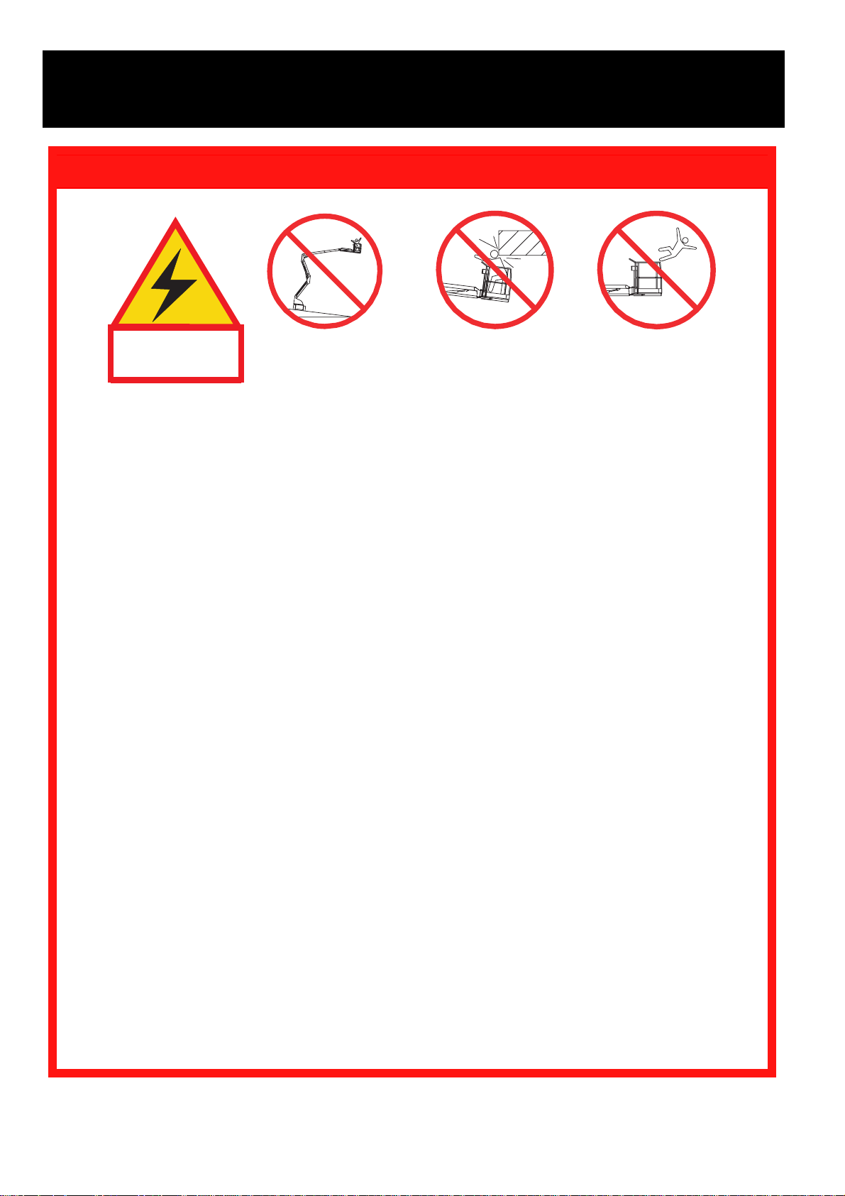
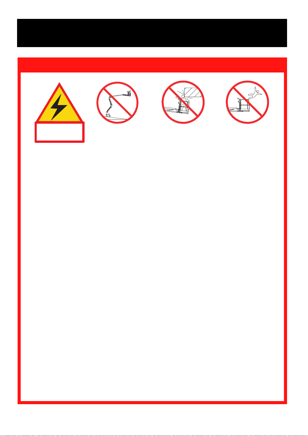
Electrocution Hazard
SAFETY RULES
Tip Over Hazard Collision Hazard Fall Hazard
THIS MACHINE IS
NOT INSULATED.
USE OF THE AERIAL WORK PLATFORM: This aerial work platform is intended to lift persons and his tools as well as
the material used for the job. It is designed for repair and assembly jobs and assignments at overhead workplaces
(ceilings, cranes, roof structures, buildings etc.). All other uses of the aerial work platform are prohibited!
THIS AERIAL WORK PLATFORM IS NOT INSULATED! For this reason it is imperative to keep a safe distance from
live parts of electrical equipment!
ALL occupants must wear an approved fall restraint properly attached to designated platform anchorage point. Attach
only one fall restraint to each anchorage point.
Exceeding the specified permissible maximum load of 225 kg (500 lbs.) or two persons on the platform is prohib-
ited!
The use and operation of the aerial work platform as a lifting tool or a crane (lifting of loads from below upwards or
from up high on down) is prohibited!
NEVER exceed 200 N (45 lbs.) of side force per occupant.
DISTRIBUTE all platform loads evenly on the platform.
NEVER operate the machine without first surveying the work area for surface hazards such as holes, drop-offs,
bumps, curbs, or debris; and avoiding them.
OPERATE machine only on surfaces capable of supporting wheel loads.
NEVER operate the machine when wind speeds exceed 45 km/h (28 mph) (12,5 m/sec.= Beaufort scale 6).
IN CASE OF EMERGENCY push emergency stop button to deactivate all powered functions.
Climbing up the railing of the platform, standing on or stepping from the platform onto buildings, steel or prefab
concrete structures, etc., is prohibited!
Dismantling the swing gate or the liftable bar or other railing components is prohibited! Always make certain that
the swing gate or the liftable bar is closed and securely locked! It is prohibited to keep the swing gate or the
liftable bar in an open position (e.g. held open with tie-straps) when the platform is raised!
To extend the height or the range by placing of ladders, scaffolds or similar devices on the platform is prohibited!
INSPECT the machine thoroughly for cracked welds, loose or missing hardware, hydraulic leaks, loose wire connections,
and damaged cables or hoses before using.
VERIFY that all labels are in place and legible before using.
NEVER use a machine that is damaged, not functioning properly, or has damaged or missing labels.
IF ALARM SOUNDS while boom is elevated, STOP, carefully retract boom and lower platform without rotating. Move
machine to a firm, level surface.
To bypass any safety equipment is prohibited and presents a danger for the persons on the aerial work platform
and in its working range.
NEVER charge batteries near sparks or open flame. Charging batteries emit explosive hydrogen gas.
Modifications to the aerial work platform are prohibited or permissible only at the approval by UpRight.
NEVER tow the machine. Transport by truck or trailer only.
AFTER USE, secure the work platform from unauthorized use by turning both key switches off and removing key.
NEVER operate the
boom or drive with
platform elevated
unless on firm level
surface.
NEVER position the
platform without first
checking for overhead
obstructions or other
hazards.
NEVER climb, stand or sit
on platform guardrails or
midrail.
2
Page 3
Introduction
This manual covers the operation of internal combustion
powered models of the AB62 Articulated Boom. This
manual must be stored on the machine at all times.
Pre-Operation and Safety
Inspection
Carefully read, understand and follow all safety
rules, labels, and operating instructions, then
perform the following steps each day before use.
Perform a complete visual inspection of the entire unit
prior to operating. Check the following areas for discrepancies:
1. Open covers and check hydraulic components / hoses
for damage or leaks. Check electrical components /
wiring for damage or loose connections.
2. Inspect chassis, axles, hubs, and steering linkage for
damage, deformation, buckled paint, loose or missing
hardware, and cracked welds.
3. Check tires for damage. Check for punctures, and
inflation (air filled only); tire pressure must be 5.5 bar
(80 psi).
4. Check all hoses / cables for wear.
5. Inspect elevating assembly for damage, deformation,
buckled paint, loose or missing hardware, and
cracked welds.
6. Inspect platform and guardrails for damage, deformation, buckled paint, loose or missing hardware, and
cracked welds. Ensure that gate operates freely and
latches securely.
7. Check Hydraulic fluid level with platform fully lowered.
8. Check battery fluid level (see Battery maintenance,
page 9).
9. Check fuel level, add fuel if necessary (see Fueling, page 9).
10. Ensure that radiator is cold, check coolant level. Add
if necessary.
NEVER remove the cap from a hot radiator. Hot
coolant can cause severe burns.
4. Press the engine start button to crank the engine;
release when engine starts. If engine is cold: press
and hold the choke button while starting gasoline /
propane models; press the glow plug button and hold
for six seconds prior to starting diesel models.
5. Push in the chassis emergency stop button engine
should stop. Repeat for platform emergency stop
button. Return both emergency stop buttons to the
ON position, and start engine.
6. Operate each function switch to raise / lower, extend /
retract, rotate left / right, each section of the elevating
assembly and observe the operation of the machine.
All functions should operate through full cycle
smoothly. (Make sure that the Boom Speed Control
is not at zero).
7. Turn chassis key switch to platform.
8. Mount the platform, close sliding rail, and attach
approved fall restraint to designated platform anchorage
point (if required by National Legislation). Attach only
one fall restraint to each point.
9. Start the engine.
10. Without depressing the foot switch, move the drive
control handle, machine should not function.
11. Depress the foot switch and move the drive control
handle forward and reverse. Observe that proportional
functions operate smoothly, and that brakes apply
quickly after control is released.
12. While depressing foot switch, operate steer switch to
left and right. Observe that steering wheels turn
properly.
13. While depressing foot switch, turn function speed
control knob to desired setting, and operate boom
controls. Observe that boom operates smoothly, and
that upper boom, jib, turret rotation, platform level,
and platform rotation controls operate proportionally in
conjunction with function speed control knob. Observe
that platform maintains level when boom is elevated.
14. With the upper boom elevated (0.3 m) one foot,
operate drive control handle. Observe that drive speed
is limited to creep (0,3 m [1 foot] per second). Lower
upper boom to stowed position.
15. Press the service horn button. Observe that horn is
audible.
SYSTEM FUNCTION INSPECTION
Note: Refer to Figures 1 through 4 for chassis and
platform control locations.
1. Before performing the following tests, check area
around machine and overhead for obstructions, holes,
drop-offs, and debris.
2. Turn chassis key switch to chassis, and turn on
(rotate clockwise) emergency stop switches at the
chassis control panel and at the platform control
panel.
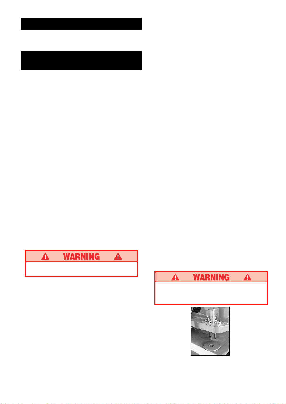
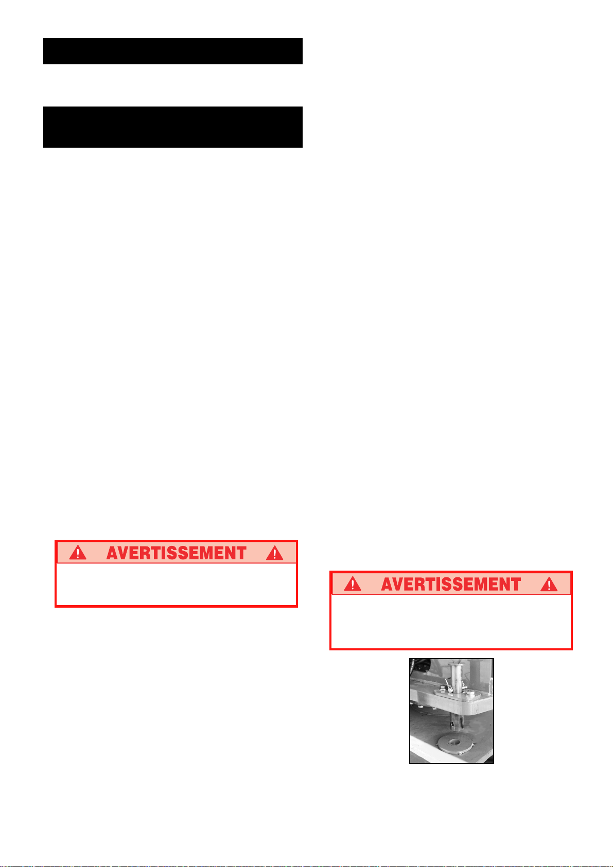
3. Retract Locking Bolt. See Figure 1.
DO NOT use a machine that is damaged or
malfunctioning. Tag and remove the unit from
service until it is repaired.
Figure 1: Locking Bolt
3
Page 4
Controls and Indicators
Operation
1
2
7
8
9
10
13
14
15
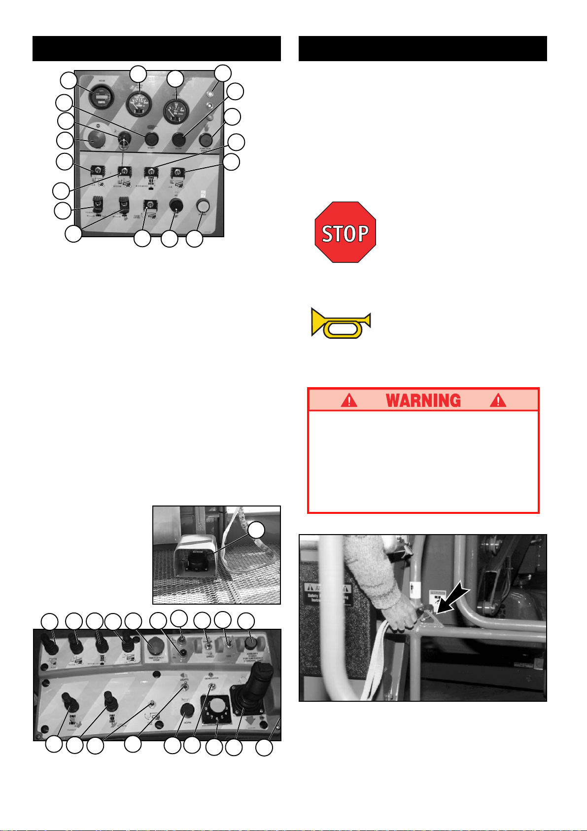
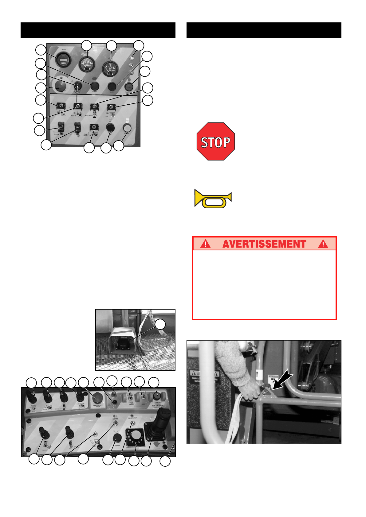
Figure 2: Chassis Controls
1. Hour Meter
2. Water Temp.
3. Oil Pressure
4. Breaker
5. Choke, Glow Plug Light
6. Enable
7. Engine Start
8. Key Switch
9. Emergency Stop
10. Riser
11. Boom Extend
12. Jib Raise
13. Boom Raise
14. Turret Rotate
15. Cage Rotate
16. Cage Level
17. Boom Hi/Low Speed
18. Auxiliary Power
19. Riser
16
3
4
5
6
11
12
18
17
20. Boom Raise
21. Boom Extend
22. Jib Raise
23. Emergency Stop
24. Red-Engine Temp
25. Yellow-Tilt
26. Hi/Low Speed
27. Gas/Prop. Select
Glow Plug Light
28. Aux. Power
29. Turret Rotate
30. Cage Rotate
31. Cage Level
32. Auxiliary Light
33. Horn
34. Generator
35. Boom Speed
36. Joystick/Interlock
37. Key Switch
38. Foot Switch
Before operating work platform insure that:
Pre-operation and safety inspection has been
completed, and any discrepancies have been
corrected.
The operator has been thoroughly trained on the
operation of the machine.
The work area is clear of all obstructions, holes,
drop-offs, or persons in the route of travel.
The surface is capable of supporting wheel loads.
Refer to figures one and two for control locations.
Emergency Stop
At any time during operation, press the emergency stop
button to stop all functions in an emergency.
Service Horn
At any time during operation, press the service horn
button to sound an audible warning if necessary.
I
f National Legislation requires:
Always wear an approved fall restraint properly
attached to designated platform anchorage point
when driving or elevating the machine (see
figure 4).
Attach only one fall restraint to each anchorage
point.
Figure 3: Foot Switch
19
29
21 22 23
20
30
31
Figure 4: Platform Controls
32
24
33
25
34
26
35
27
36
38
28
Figure 5: Typical Fall Restraint
Anchorage Point
37
4
Page 5

Starting the engine
From the lower controls
1. Turn the chassis key switch to chassis position.
2. Press the start button to crank the engine. Release
when the engine starts.
3. When the engine is cold: press and hold the choke
button while starting gasoline / propane engines;
press and hold the glow plug button for six seconds
prior to starting diesel engines.
From the platform controls
1. Turn the chassis key switch to platform controls.
2. Turn the platform switch fully clockwise to crank the
engine. Release when engine starts.
3. When the engine is cold: Press and hold the choke
button while starting gasoline / propane engines.
Press and hold the glow plug button for six seconds
prior to starting the diesel engine.
Driving
With Boom Lowered
1.
Turn chassis key switch to platform, and turn on (turn
clockwise) the chassis emergency stop switch.
2. Mount the platform, close sliding rail.
3. Attach approved fall restraint (If required by National
Legislation) to designated platform anchorage point.
Attach only one fall restraint to each point.
4. Start engine.
5. Check that the area around and above the work
platform is clear of obstructions, holes, drop-offs,
persons in the route of travel, and the surface is
capable of supporting wheel loads.
6. Depress the foot switch (alternately the Drive Handle
Button may be pressed) and move the drive control
handle forward to travel forward and reverse to travel in
the reverse direction.
Note: When the boom is rotated to the front of the
chassis (steering wheels aft) directions of travel and
steering will be reversed. Observe the color coded
arrows on the control panel near the drive control
handle, and on the chassis. They will indicate the
direction of travel when the drive control handle is
moved.
With Boom Elevated
Travel with boom elevated is restricted to firm level
surfaces only.
When driving elevated, the machine will travel at creep
speed (0,3 m [1 foot] per second).
Steering
1. While depressing the foot switch, push the steering
switch (located on top of the control handle) to the left
to turn left, and right to turn right.
Note: Steering is not self centering. Wheels must be
returned to the straight ahead position by operating
the steering switch.
POSITIONING THE PLATFORM
Positioning the platform as close as possible to the work
area requires some planning. First, you must survey the
work site to find a suitable place to park the machine.
This must be a firm level surface as close as possible to
the work area. Take into consideration all obstructions on
the ground and overhead and avoid them.
Once you have moved the machine to a firm level surface
as near as possible to the work area, follow the instructions on page 6 to position the platform as close to the
work area as possible.
Always, before operating any function, check the area
around and overhead for any obstructions or electrical
conductors.
Multifunction Controls
The UpRight AB62 employs the use of multifunction
controls. This means that riser or boom extension will
function at full speed while simultaneously operating
upper boom, jib, turret, or rotating the platform.
The turret may be rotated while driving when Boom is
lowered, if necessary to make turns in tight areas. All
other boom functions will not operate while driving.
Lower Control Operation
All boom functions will operate at fixed speed.
1. Turn chassis keyswitch to chassis controls.
2. With engine running, operate boom control switches
to position the platform.
3. The High/Low switch will select between maximum
speed and a lower fixed boom speed.
Stop When Tilt
Alarm Sounds
Warning: If tilt alarm sounds,
retract boom and drive machine
to a level surface.
5
Page 6
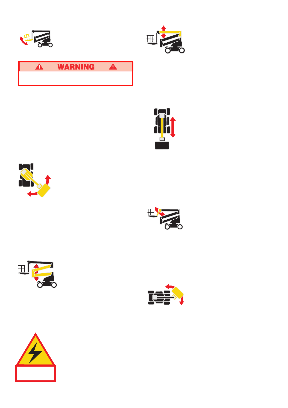
Leveling the Platform
DO NOT operate the machine if the platform
does not maintain level when elevated.
Note: Platform leveling can be performed only with
the boom stowed and should be done only to
calibrate the automatic leveling system.
1. Set the function speed control dial to the desired
setting. Rotate the dial clockwise to increase speed,
counterclockwise to decrease. If you are not sure what
speed to use, start out slow; the speed can be varied
while operating the function.
2. While depressing the foot switch, push the platform
level control switch forward to swing the platform
upward, rearward to swing the platform downward.
Release the switch to stop leveling.
Rotating the Turret
1. Set the function speed control dial to the desired
setting. Rotate the dial clockwise to increase speed,
counterclockwise to decrease. If you are not sure what
speed to use, start out slow; the speed can be varied
while operating the function.
2. While depressing the foot switch, push the turret
rotation control lever right to rotate counterclockwise,
left to rotate clockwise. Release the switch to stop
rotation. Observe the area around the boom when
rotating the turret to avoid any obstructions.
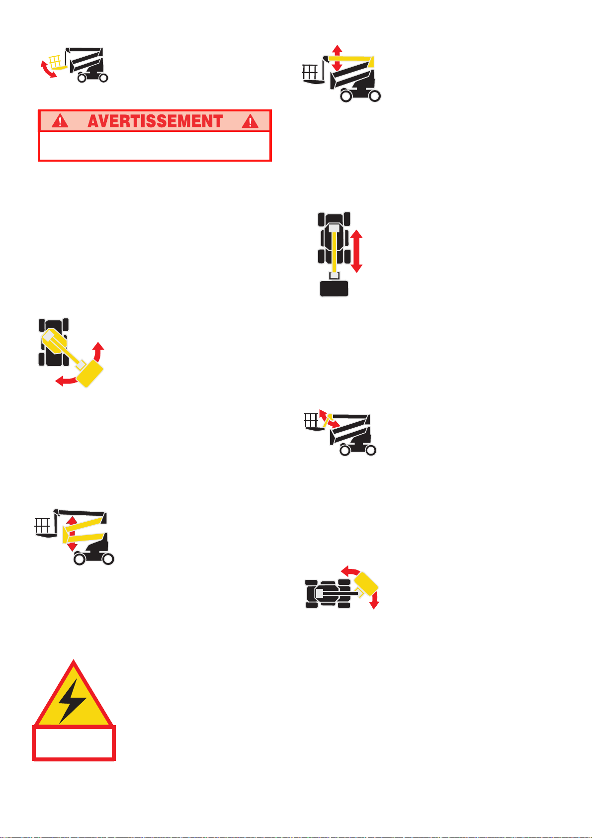
Elevating the Riser
Elevating the Upper Boom
1. Set the function speed control dial to the desired
setting. Rotate the dial clockwise to increase speed,
counterclockwise to decrease. If you are not sure what
speed to use, start out slow; the speed can be varied
while operating the function.
2.
While depressing the foot switch, push the upper boom
control lever forward to elevate the upper boom, rearward
to lower the upper boom. Release the control lever to
stop elevating / lowering.
Extending the Upper
Boom
1. Set the function speed control dial to the desired
setting. Rotate the dial clockwise to increase speed,
counterclockwise to decrease. If you are not sure what
speed to use, start out slow; the speed can be varied
while operating the function.
2. While depressing the foot switch, push the boom
extension control lever rearward to extend the boom,
forward to retract the boom. Release the control lever
to stop extending / retracting.
Elevating the Jib
1. Set the function speed control dial to the desired
setting. Rotate the dial clockwise to increase speed,
counterclockwise to decrease. If you are not sure what
speed to use, start out slow; the speed can be varied
while operating the function.
2. While depressing the foot switch, push the jib control
lever forward to elevate the jib, rearward to lower the jib.
Release the control lever to stop elevating / lowering.
1. Set the function speed control dial to the desired
setting. Rotate the dial clockwise to increase speed,
counterclockwise to decrease.
2. While depressing the foot switch, push the riser
control lever forward to elevate the riser, rearward to
lower the riser. Release the control lever to stop
elevating / lowering.
This machine is not insulated. Follow
your national safety standards and
maintain the required safety distance
THIS MACHINE IS
NOT INSULATED.
when working near
energized equipment.
Rotating the Platform
1. Set the function speed control dial to the desired
setting. Rotate the dial clockwise to increase speed,
counterclockwise to decrease. If you are not sure what
speed to use, start out slow; the speed can be varied
while operating the function.
2. While depressing the foot switch, push the platform
rotation control lever right to go counterclockwise and
left to go clockwise. Release the lever to stop rotation.
6
Page 7
EMERGENCY OPERATION
In the event of powered function failure, the platform may
be lowered by using the Auxiliary Power Unit. Hold in the
Auxiliary Power Button and operate the lowering controls.
Important: Emergency Stop Buttons should be used
in an emergency only.
NOTE: Emergency Stop does not function during
Auxiliary Powered operation.
NEVER climb down the elevating assembly. If
controls do not respond, ask someone on the
ground to lower the boom manually.
EMERGENCY TOWING
Perform the following only when the machine will not
operate under its own power and it is necessary to move
the machine or when winching onto a trailer for transportation.
1. Insure that the platform is fully lowered, and that the
turret is rotated so that the platform is to the rear of
the machine.
2. Attach chain / cable of sufficient strength for towing
the machine to front or rear tie down lugs.
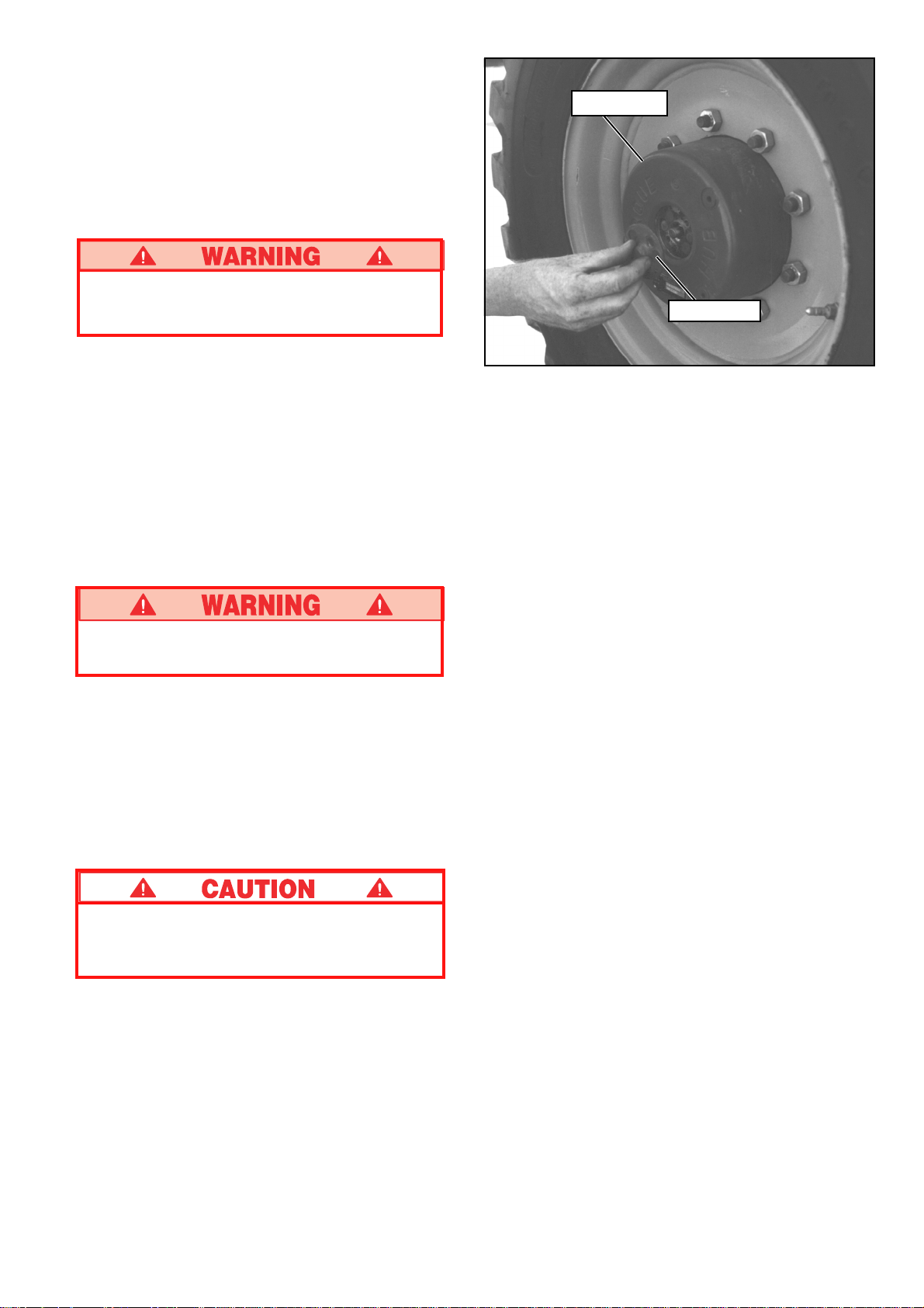
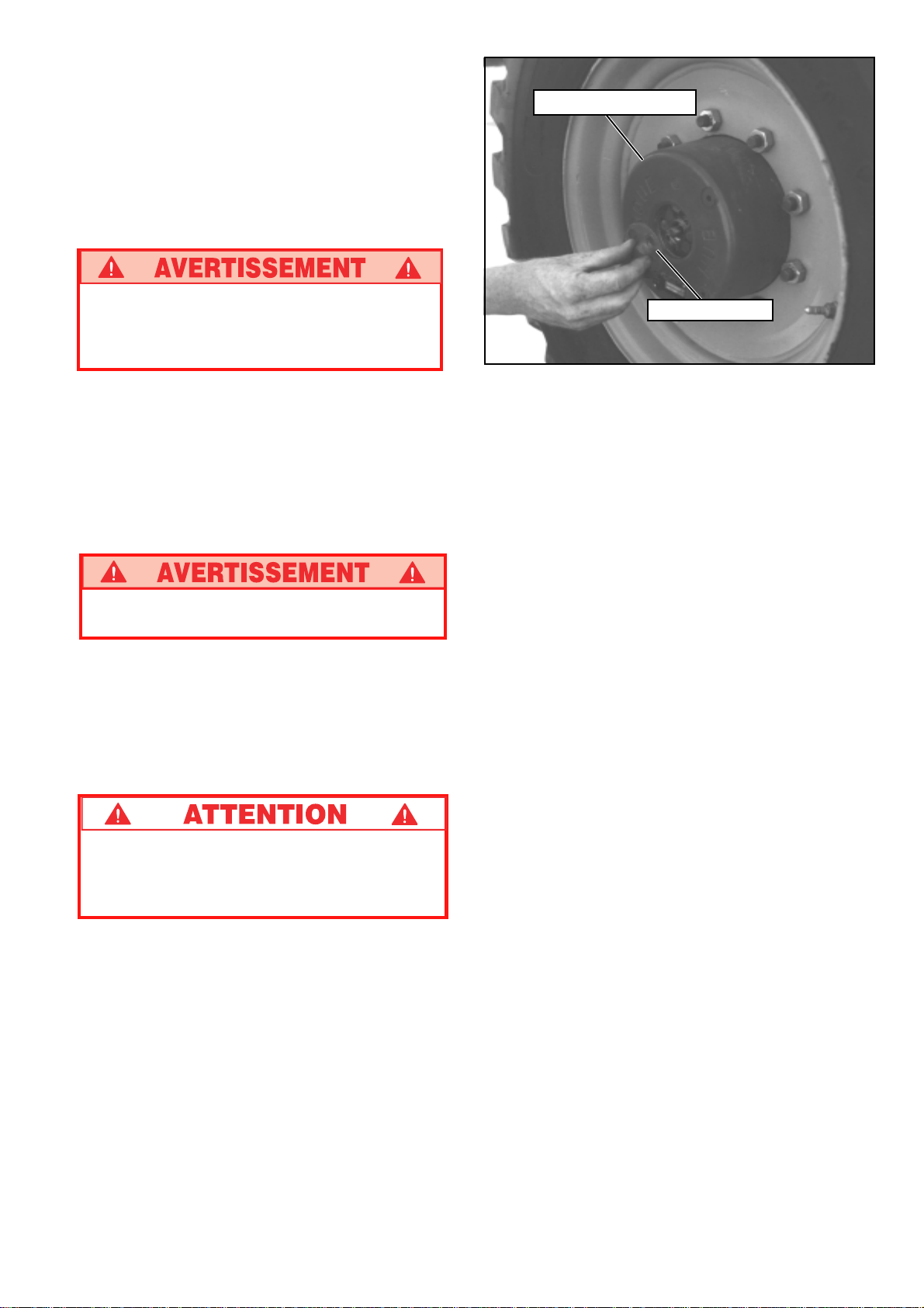
Drive Hub
Center Cap
Figure 6: Disengaging Drive Hub
AFTER USE EACH DAY
1. Ensure that the platform is fully lowered.
2. Park the machine on firm level ground, preferably
under cover, secure against vandals, children or
unauthorized operation.
3. Turn the upper key switch to OFF, the lower key
switch to platform and remove all keys to prevent
unauthorized operation.
Chock wheels before disengaging hubs. Machine
may roll.
3. Refer to Figure 6 and disengage all four drive hubs.
Remove two screws and center cap. Reinstall center
cap in the opposite direction.
4. When ready to move the machine, remove the
chocks. Toe or winch into position and replace
chocks.
5. Engage all four drive hubs by returning the center
caps to their original orientation.
DO NOT move the machine faster than 5 km/h
[3 mph]. Faster speeds will damage drive
components and void warranty.
7
Page 8
Transportation
BY CRANE
Stand clear of machine when lifting.
Check specifications on back page, insure that
crane and slings are of correct capacity to lift
weight of unit.
1. Insure that boom is fully lowered and retracted.
2. Attach straps to chassis lifting lugs only. Insure that
straps are adjusted properly to keep unit level when
lifting.
BY TRUCK OR TRAILER
1. Insure that boom is fully lowered and retracted.
2. Raise jib before machine starts up or down ramp to
avoid platform contacting ground.
3. Maneuver the machine onto bed of truck/trailer.
4. When winching, follow instructions for emergency
towing on page 7. Attach winch cable to front tie
down lugs.
Do not winch machine faster than 5 km/h [3 mph].
5. After winching, insure that brakes are set.
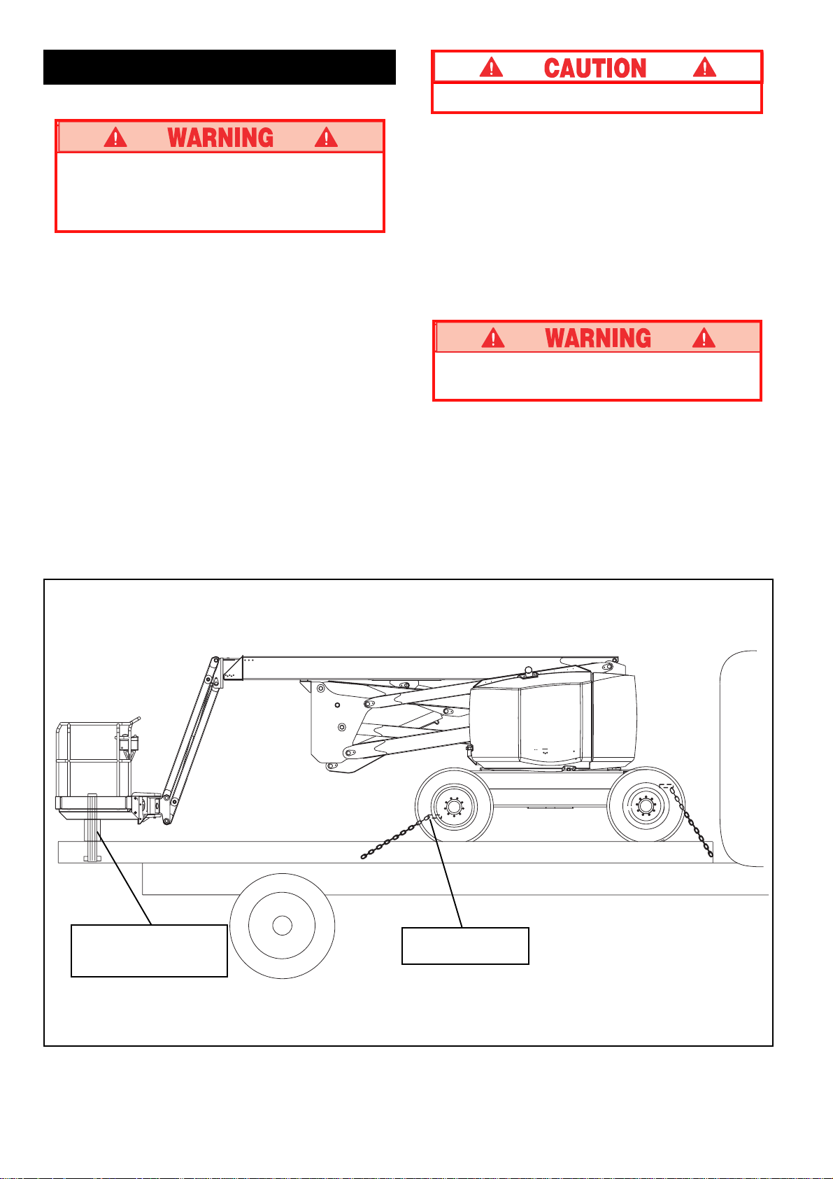
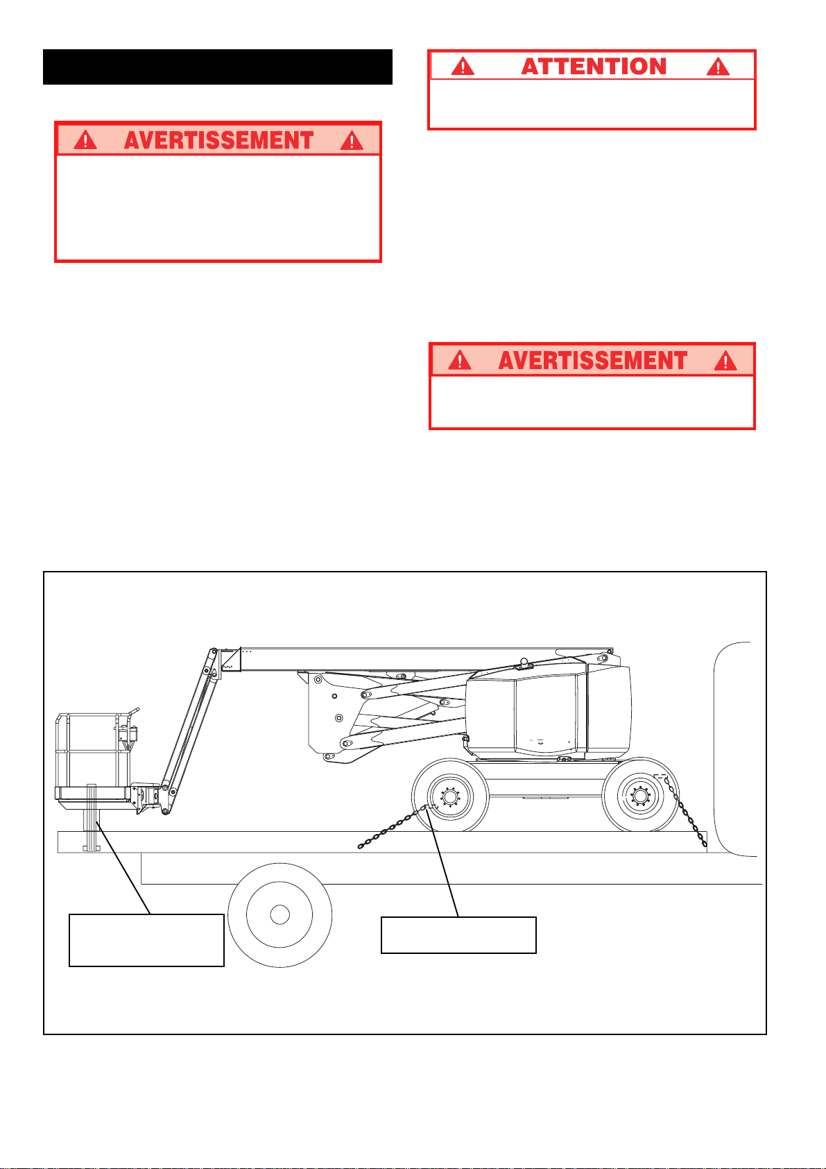
6. Secure the machine to the transport vehicle using
chains / straps of adequate load capacity (refer to
specifications, back page) attached to chassis tie
down lugs (see Figure 7).
7. Place a wooden block (20 cm x 10 cm x 75 cm
[8" x 4" x 28"]) under platform support braces as
shown (see Figure 7).
8. Attach ratchet strap; under platform floor grating, over
support braces (see Figure 7). Tighten securely, do
not overtighten.
NEVER elevate the machine while on a truck or
trailer.
Wooden Block
20 cm x 10 cm x 75 cm
(8” x 4” x 28”)
Chassis Tie Down /
Lifting Lug (typ.)
Figure 7: Securing the Machine for Transportation
8
Page 9
FUELING
Maintenance
BATTERY MAINTENANCE
Gasoline
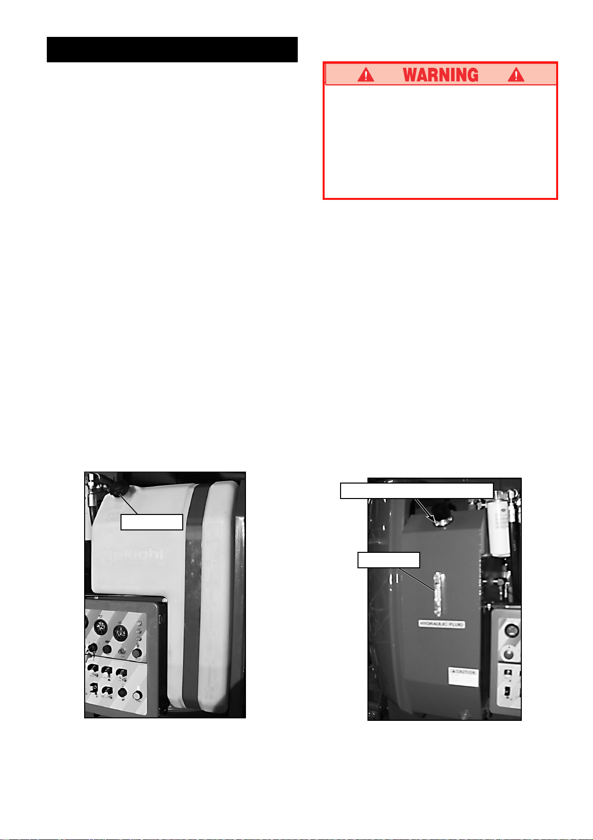
1. Open left turret cover, open fill pipe cap.
(See Figure 8).
2. Fill to capacity with unleaded motor fuel only.
3. Fuel tank full capacity is 159 L [42 US gallons].
Diesel
1. Open left turret cover, open fill pipe cap.
(See Figure 8).
2. Fill to capacity with diesel motor fuel. Use diesel fuel
as per EN950, do not use residual or blend.
3. Fuel tank full capacity is 159 L [42 US gallons].
HYDRAULIC FLUID
1. Check level at sight gauge inside engine compartment right hand side with the platform fully lowered.
(Figure 9)
2. If necessary, fill to capacity with clean (ISO 46
summer - ISO 32 winter) compatible hydraulic fluid.
3. Open filler / breather cap to add hydraulic oil.
4. Replace cap.
5. Properly dispose of waste fluid.
Hazard of explosive gas mixture. Keep sparks,
flame and smoking materials away from batteries.
Always wear safety glasses when working with
batteries.
Battery fluid is highly corrosive. Rinse away any
spilled fluid thoroughly with clean water.
Always replace batteries with UpRight batteries
or manufacturer approved replacements.
Check battery fluid level daily, especially if work platform
is being used in a warm, dry climate.
If electrolyte level is lower than 10 mm (3/8 in.) above
plates add distilled water only. DO NOT use tap water it
will shorten battery life.
Keep terminals and top of battery clean.
TIRES
Tire selection can affect the stability of the machine. Use
only tires supplied by UpRight unless approved by the
manufacturer in writing. Check air filled tire air pressure
daily 5.5 bar [80 psi].
LUBRICATION
Refer to service manual for lubrication chart and
guidelines.
Fuel Fill Pipe
Hydraulic Oil Filler / Breather Cap
Level Gauge
Figure 8: Fuel Fill Pipe
Figure 9: Hydraulic Oil Filler / Breather Cap
9
Page 10

ROUTINE SERVICE
Use the following table as a guide for routine maintenance. Inspection and maintenance shall be performed
by personnel who are trained and familiar with mechanical and electrical procedures. Refer to the Service
Manual for complete service instructions.
Please copy this page and use the Routine Service Table
as a checklist when inspecting a machine for service.
Routine Service Table
Routine Service Table Key
Interval
Daily = each shift (every day) or every eight hours
30D = every month (30 days) or every 50 hours
3M = every 3 months or 125 hours
6M = every 6 months or 250 hours
1Y = every year or 500 hours
2Y = every 2 years or 1000 hours
A = Acceptable
N = No / Not Acceptable
R = Repaired / Acceptable
COMPONENT INSPECTION OR SERVICES INTERVAL A N R
Engine Oil Check level and condition Daily
Engine Fuel Check fuel level Daily
System Check for leaks Daily
Battery Check electrolyte level Daily
Engine Check coolant level (with engine cold) Daily
Coolant Replace coolant 3M
Hydraulic Check oil level Daily
Fluid * Change filter 6M
Hydraulic Check for leaks Daily
System Check hose connections 30D
Emergency Check operation of emergency override Daily
Hydraulic valves and hand pump
System Check operation of emergency override power unit Daily
Controller Check operation of all controls Daily
Control Check the exterior of the cable Daily
Cable for pinching, binding or wear
Platform Check fasteners for proper torque Daily
Floor and Check welds for cracks Daily
Rails Check condition of platform Daily
Tires Check for damage Daily
Hydraulic Wipe clean 30D
Pump Check for leaks at mating surfaces 30D
Hydraulic Check hydraulic drive motor operation Daily
Drive Check hoses, fittings, and valve block
System for leaks
Check for leaks Daily
Change oil & filter (Dual Fuel) 200 HOURS
Change oil & filter (Diesel) 500 HOURS
Replace fuel filter 6M
Check air cleaner Daily
Clean exterior 3M
Clean terminals 3M
Drain and replace with ISO 46 compatible oil 2Y
Check hoses for exterior wear 30D
Check condition of anchorage points Daily
Check condition of operators manual Daily
Check air pressure 5.5 bar [80 psi]) Daily
Check lug nuts (torque to 123 Nm [90 ft. lbs.]) 30D
Check for hose fitting leaks Daily
Check mounting bolts for proper torque 30D
Daily
COMPONENT INSPECTION OR SERVICES INTERVAL A N R
Steering Check fittings for proper torque 6M
System Oil all pivot points 3 0D
Elevating Inspect for structural cracks Daily
Assembly Check pivot points for wear 30 D
Chassis Check hoses for pinch or rubbing points Daily
Turret Check ring gear for proper lubrication and wear Daily
Torque Check for leaks Daily
Hubs Check oil level 250H/6 M
Lift Check the cylinder rods for wear 30D
Cylinders Check pivot pin retaining bolts
Entire Check for and repair collision damage Daily
Unit Check fasteners for proper torque 3M
Labels Check for peeling, missing, or unreadable Daily
Check steering cylinder for leaks 30 D
Check linkage for wear areas 30 D
Check for missing / loose retainers Daily
Check pivot pin retaining bolts
for proper torque
Check members for deformation Daily
Check component mounting for proper torque 6M
Check welds for cracks Daily
Lubricate ring gear (MoS
Change oil after break-in period 50H/30D
Change oil (SAE 90 gear oil) 2000H/2Y
for proper torque
Check seals for leaks 30D
Inspect pivot points for wear 30D
Check fittings for proper torque 30D
Check for corrosion, remove and repaint 3M
Lubricate 30D
labels & replace
grease) 150H/3M
2
30D
30D
Service Report
Date: _________________________________________
Owner: _______________________________________
*ISO grade 46, for temperatures above 32°F (0°C).
*For colder climates: ISO grade 32, for temperature range of 0°F (-17° C)
up to 32° F (0°C).
*ISO grade 15, for temperatures below 0°F (-17° C).
Model No: ___________ Serial No: ________________
Serviced By: __________________________________
Service Interval:________________________________
10
Page 11
Specifications*
SPECIFICATION AB62 4WD DIESEL
Height
Working height maximum 20.7 m [68 ft.]
Platform height maximum 18,9 m [62 ft.]
Platform step in height 343 mm [13.5 in.]
Up and over height 9.1 m [30 ft.]
Drivable height 18.9 m [62 ft.]
Horizontal outreach 10.7 m [35 ft.]
Turret rotation 360° continuous
Platform rotation 180°
Tail swing (Stowed) 0
Jib length 1,9 m [6 ft. 4 in.]
Jib arc 140°
Inside turning radius 2.5 m [8 ft.]
Outside turning radius 5.5 m [18 ft.]
Drive speed (boom stowed,travel) 6.8 km/h [4.25 mph] (high)
2.6 km/h [1.60 mph] (low)
Drive speed (elevated) 0.96 km/h [0.6 mph]
Gradability 22° [40%]
Dimensions (boom stowed)
Platform Size 1 m x 1.8 m [39 in. x 72 in.]
Optional 2.4 m (8 ft.) Platform 1 m x 2.4 m [39 in. x 96 in.]
Guardrail height 1.14 m [45 in.]
Toeboards 0.15 m [6 in.]
Maximum platform capacity 227 kg [500 lbs.]
Maximum no. of occupants 2
Weight 10,614 kg [23,400 lbs.]
Overall height 2,5 m [8 ft. 2 in.]
Overall length 8.2 m (or 7.2 m min.)
[27 ft.
or 23 ft. 6 in. min.]
Overall width 2.3 m [7 ft. 7.5 in.]
Wheel base 2.6 m [8 ft. 6 in.]
Ground Clearance 0.46 m (center) 0.32 m (axle)
[18 in. (center) 12.5 in. (axle)]
Power source Perkins 704-30
System voltage 12VDC
Maximum Hyd. Pressure 345 bar [5000 psi]
Controls Electric Proportional
Tires 19x15 NHS - 14 PLY
AB62 4WD GASOLINE
20.7 m [68 ft.]
18.9 m [62 ft.]
343 mm [13.5 in.]
9.1 m [30 ft.]
18.9 m [62 ft.]
10.7 m [35 ft.]
360° continuous
180°
0
1.9 m [6 ft. 4 in.]
140°
2,5 m [8 ft.]
5,5 m [18 ft.]
6.8 km/h [4.25 mph] (high)
2.6 km/h [1.6 mph] (low)
0.96 km/h [0.6 mph]
22° [40%]
1 m x 1.8 m [39 in. x 72 in.]
1 m x 2.4 m [39 in. x 96 in.]
1.14 m [45 in.]
0.15 m [6 in.]
227 kg [500 lbs.]
2
10.614 kg [23.400 lbs.]
2.5 m [8 ft. 2 in.]
8.2 m (or 7.2 m min.)
23 ft. 6 in. min.]
2.3 m [7 ft. 7.5 in.]
2.6 m [8 ft. 6 in.]
0.46 m (center) 0.32 m (axle)
[18 in. (center) 12.5 in.(axle)]
GM 3.0 L
12VDC
345 bar [5000 psi]
Electric Proportional
19x15 NHS - 14 PLY
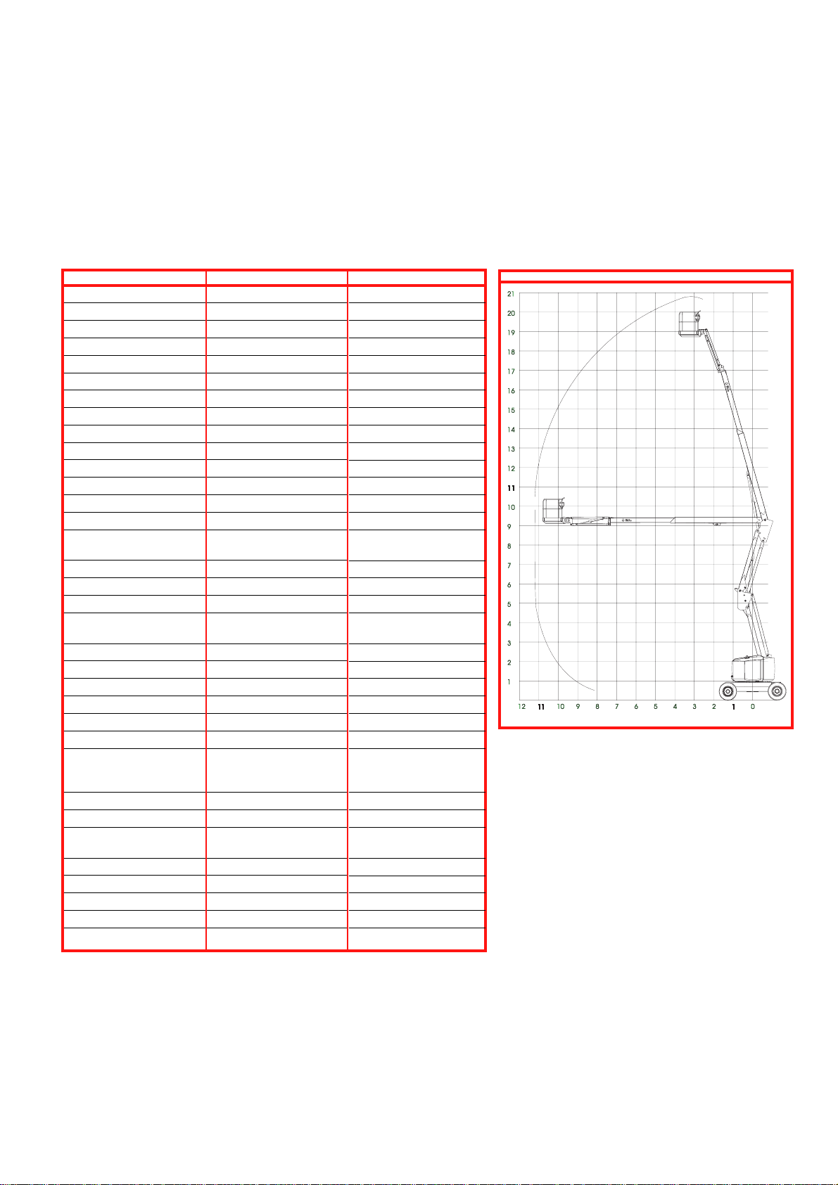
REACH ENVELOPE DIAGRAM
DIMENSIONS IN METRES
[27 ft. or
* Specifications subject to change without notice.
Refer to Service Manual for complete parts and service information.
11
Page 12
Version française
CONSIGNES DE SÉCURITÉ
Risque d’électrocution
CETTE MACHINE
N’EST PAS ISOLÉE.
USAGE DE LA PLATE-FORME ÉLÉVATRICE : Cette plate-forme élévatrice est destinée au levage du personnel, de son
outillage et des matériaux utilisés sur le chantier. Elle est conçue pour les travaux de réparations et d’assemblage sur les
points élevés (plafonds, grues, charpentes de toit, immeubles, etc.). Tout autre usage de la plate-forme élévatrice est
interdit !
CETTE PLATE-FORME ÉLÉVATRICE N’EST PAS ISOLÉE ! C’est pourquoi il est impératif de rester à distance sûre des
lignes et équipements électriques sous tension !
TOUS les occupants doivent porter un cordon de sûreté antichute correctement fixé sur un point d’ancrage de la plate-
forme. N’accrocher qu’un câble de sûreté par point d’ancrage.
Il est interdit de dépasser la charge maximum admissible de 225 kg (500 lb) ou deux personnes !
Il est interdit d’utiliser la plate-forme comme appareil de levage ou grue levage des charges par le dessous ou le
dessus.
NE JAMAIS dépasser 45 lb (200 N) de force latérale par occupant.
RÉPARTIR uniformément toutes les charges placées sur la plate-forme.
NE JAMAIS utiliser la machine sans avoir d’abord vérifié si la zone de travail est exempte de dangers tels que des
trous, dénivellations, bosses, trottoirs ou débris.
N’UTILISER la machine que sur des surfaces pouvant supporter la charge des roues.
NE JAMAIS utiliser la machine lorsque le vent souffle à plus de 45 km/h (28 mi/h) (12,5 m/sec. = [6 sur l’échelle de
Beaufort]).
EN CAS D’URGENCE, appuyez sur le bouton d’arrêt d’urgence (emergency stop) pour mettre toutes les commandes hors
fonction.
Il est interdit de monter ou de se tenir sur les garde-corps de la plate-forme et de passer de la plate-forme à un
immeuble, une structure préfabriquée, etc. !
Il est interdit de retirer le portillon pivotant, la barre de sûreté ou toute autre pièce de garde-corps ! Toujours vérifier
que le portillon et la barre de sûreté sont fermés et verrouillés ! Il est interdit de maintenir le portillon ou la barre de
sûreté en position ouverte (par exemple au moyen d’attaches) lorsque la plate-forme est élevée !
Il est interdit d’accroître la hauteur ou la portée de la plate-forme au moyen d’échelles, échafaudages ou autres
dispositifs similaires !
INSPECTER minutieusement la machine en vue de soudures fissurées, de pièces de boulonnerie manquantes ou
desserrées, de fuites hydrauliques, de branchements électriques desserrés ou de câbles et flexible endommagés avant
d’utiliser la machine.
VÉRIFIER que tous les autocollants sont en place et lisibles avant d’utiliser la machine.
NE JAMAIS utiliser une machine qui est endommagée, qui ne fonctionne pas correctement ou dont les autocollants sont
manquants ou endommagés.
SI L’ALARME RETENTIT pendant que la plate-forme est élevée, ARRÊTER, rétracter la flèche avec précaution et
abaisser la plate-forme sans la faire pivoter. Conduire la machine jusqu’à une surface plane et ferme.
Il est interdit de mettre tout dispositif de sécurité hors service, ce qui mettrait en danger les personnes à bord de la
plate-forme et celles se trouvant dans la zone de travail.
NE JAMAIS charger les batteries à proximité d’étincelles ou d’une flamme vive. Lors de la charge, les batteries dégagent
de l’hydrogène, un gaz explosif.
Sauf autorisation de la part d’UpRight, toute modification de la plate-forme est interdite.
NE JAMAIS remorquer la machine. Elle ne doit être transportée que sur un camion ou une remorque.
APRÈS AVOIR UTILISÉ la plate-forme élévatrice, mettre le contacteur à clé en position d’arrêt (off), puis retirer la clé
afin d’empêcher l’utilisation non autorisée de la plate-forme.
Risque de basculement
NE JAMAIS actionner la
flèche ou conduire la
machine avec la plate-forme
élevée sur une surface qui
n’est pas plane et ferme.
Risque de collision
NE JAMAIS élever la
plate-forme avant de
s’être assuré de l’absence
d’obstacles en hauteur ou
autres dangers.
Risque de chute
NE JAMAIS monter, ni
se tenir debout ou assis
sur les rampes du gardecorps.
12
Page 13
Introduction
Ce manuel traite de l’utilisation des machines AB62 à flèche
articulée et moteur à combustion interne. Il doit être conservé sur la
machine en permanence.
Vérifications préliminaires et
inspection de sécurité
Lire attentivement et veiller à bien comprendre toutes les
consignes de sécurité, tous les autocollants et toutes les
instructions de sécurité, puis effectuer toutes les vérifications ci-dessous, chaque jour, avant d’utiliser la machine.
Effectuer une inspection visuelle de toute la machine avant de
l’utiliser. Vérifier tous les points suivants :
1. Ouvrir les couvercles et examiner les composants/flexibles
hydrauliques en vue de dommages ou d’usure. Vérifier les
composants électriques en vue de dommages ou de connexions
électriques desserrées.
2. Inspecter le châssis, les essieux, les moyeux et la tringlerie de
direction en vue de dommages, déformations, peinture décollée,
pièces de boulonnerie manquantes ou desserrées et soudures
fissurées.
3. Vérifier l’état des pneus. S’assurer de l’absence de perforations
et vérifier le gonflage (pneus gonflés à l’air seulement); la
pression doit être de 5,5 bar (80 psi).
4. Vérifier l’usure de tous les câbles et flexibles.
5. Inspecter le système d’élévation en vue de dommages, déformations, peinture décollée, pièces de boulonnerie manquantes ou
desserrées et soudures fissurées.
6. Inspecter la plate-forme et les garde-corps en vue de dommages, déformations, peinture décollée, pièces de boulonnerie
manquantes ou desserrées et soudures fissurées. Vérifier que
le portillon fonctionne librement et se verrouille correctement.
7. Vérifier le niveau de fluide hydraulique avec la plate-forme
complètement abaissée.
8. Vérifier le niveau d’électrolyte (voir Entretien des batteries,
page 19).
9. Vérifier le niveau de carburant et faire l’appoint si nécessaire (voir
Approvisionnement en carburant, page 19).
10. S’assurer que le radiateur est froid et vérifier le niveau de liquide
de refroidissement. Faire l’appoint si nécessaire.
NE JAMAIS retirer le bouchon lorsque le radiateur
est chaud. Le liquide de refroidissement chaud
peut causer des brûlures graves.
ESSAI DE FONCTIONNEMENT DES
SYSTÈMES
4. Appuyer sur le bouton du démarreur (START) pour lancer le
moteur et le relâcher une fois que le moteur a démarré. Si le
moteur est froid : sur les modèles à essence/propane, maintenir
le bouton de starter (CHOKE) enfoncé pendant le démarrage;
sur les modèles diesel, maintenir le bouton de bougie incandescente (GLOW PLUG) enfoncé pendant six secondes avant de
lancer le moteur.
5. Enfoncez le bouton d’arrêt d’urgence (EMERGENCY STOP) du
châssis. Le moteur devrait s’arrêter. Faire de même avec le
bouton d’arrêt d’urgence de la plate-forme. Remettre les deux
boutons d’arrêt d’urgence en position de marche (ON) et faire
démarrer le moteur.
6. Actionner chaque interrupteur de fonction pour élever/abaisser,
étendre/rétracter, faire pivoter à droite/à gauche chacune des
sections de l’ensemble élévateur et observer le fonctionnement
de la machine. Toutes les fonctions doivent opérer en douceur
sur toute leur course. (S’assurer que la commande de vitesse
de flèche (BOOM SPEED) n’est pas sur zéro.)
7. Mettre le contacteur à clé du châssis en position plate-forme
(PLATFORM).
8. Monter sur la plate-forme, fermer la barre coulissante et
accrocher les cordons de sûreté approuvés sur les points
d’ancrages désignés de la plate-forme (si exigé par les
réglementations gouvernementales). N’accrocher qu’un câble
de sûreté par point d’ancrage.
9. Démarrer le moteur.
10. Sans appuyer sur l’interrupteur au pied, actionner le levier de
commande. La machine ne devrait pas fonctionner.
11. Appuyer sur l’interrupteur au pied et actionner le levier de
commande vers l’avant et vers l’arrière. Vérifier que les
commandes proportionnelles fonctionnent en douceur et que le
frein se serre immédiatement lorsque la commande est relâchée.
12. Tout en appuyant sur l’interrupteur au pied, actionner la
commande de direction vers la droite et vers la gauche. Vérifier
que les roues directrices tournent correctement.
13. Tout en appuyant sur l’interrupteur au pied, tourner le bouton de
commande de vitesse de fonction sur le réglage désiré et
actionner les commandes de flèche. Vérifier que la flèche
fonctionne en douceur et que les commandes de flèche
supérieure, de bras, de rotation de tourelle, de mise de niveau et
de rotation de la plate-forme fonctionnent proportionnellement à
la position du bouton de réglage de vitesse de fonction. Vérifier
que la plate-forme reste de niveau lorsque la flèche est élevée.
14. La flèche supérieure étant relevée de 0,3 m (1 pi) actionner la
commande de déplacement au sol. Vérifier que le déplacement
est limité à la vitesse d’avance rampante (0,3 m [1 pi] seconde).
Abaisser la flèche supérieure en position repliée.
15. Appuyer sur le bouton d’avertisseur de service. Vérifier que
l’avertisseur est audible.
NE PAS utiliser une machine qui est endommagée
ou ne fonctionne pas correctement. Placer des
panneaux de mise en garde et retirer la machine
du service jusqu’à ce qu’elle soit réparée.
Nota : Voir les emplacements des commandes de la plateforme et du châssis aux figures 1 à 4.
1. Avant d’effectuer les tests ci-dessous, regarder autour et audessus de la machine en vue d’obstacles, trous, dénivellations
et débris.
2. Tourner le contacteur à clé du châssis en position châssis
(CHASSIS) et activer (en les tournant vers la droite) les boutons
d’arrêt d’urgence des panneaux de commande du châssis et de
la plate-forme.
3. Rétractez l’axe de verrouillage. (Voir la figure 1).
Commandes et indicateurs
Utilisation
Figure 1 : Axe de verrouillage
13
Page 14
Commandes et indicateurs
Utilisation
1
2
7
8
9
10
13
14
15
Figure 2 : Commandes du châssis
1. Horomètre
2. Temp. eau
3. Pression d’huile
4. Disjoncteur
5. Témoin de starter,
bougie incandescente
6. Activation
7. Démarrage moteur
8. Contacteur à clé
9. Arrêt d’urgence
10. Élévateur
11. Extension flèche
12. Élévation bras
13. Élévation flèche
14. Rotation tourelle
15. Rotation cage
16. Mise de niveau cage
17. Haute/basse vitesse flèche
18. Alimentation auxiliaire
19. Élévateur
16
3
4
5
6
11
12
18
17
20. Élévation flèche
21. Extension flèche
22. Élévation bras
23. Arrêt d’urgence
24. Rouge – temp. moteur
25. Jaune – inclinaison
26. Haute/basse vitesse
27. Carb/dépl. sélect. bougie
incand.
28. Alim. aux.
29. Rotation tourelle
30. Rotation cage
31. Mise de niveau cage
32. Éclairage auxiliaire
33. Avertisseur
34. Génératrice
35. Vitesse flèche
36. Manche à balai/verrouillage
37. Interrupteur, clé de contact
38. Interrupteur au pied
Avant d’utiliser la plate-forme élévatrice, vérifier que :
Les vérifications avant utilisation et inspections de sécurité ont
été effectuées et que tous les problèmes éventuels ont été
corrigés.
L’opérateur a été dûment formé pour utiliser la machine.
La zone de travail est totalement exempte d’obstructions,
trous, dénivellations, personne ne doit se trouver sur le trajet
de la machine.
La surface est capable de supporter la charge des roues.
Consulter les figures un et deux pour les emplacements des
commandes.
Arrêt d’urgence
En cas d’urgence, à tout moment pendant l’utilisation, appuyer sur le
bouton d’arrêt d’urgence (EMERGENCY STOP) pour arrêter toutes
les fonctions.
Avertisseur de service
Si nécessaire, à tout moment pendant l’utilisation, appuyer sur le
bouton d’avertisseur de service (SERVICE HORN) pour faire retentir
une alarme sonore.
Si les réglementations gouvernementales l’exigent :
Toujours porter un cordon de sûreté approuvé
accroché sur un point d’ancrage désigné de la
plate-forme pendant la conduite ou l’élévation (voir
la figure 4).
N’accrocher qu’un câble de sûreté par point
d’ancrage.
Figure 3 : Interrupteur
au pied
19
29
20
30
21
31
22 23
32
24
33
26
34
25
Figure 4 : Commandes de la plate-forme
35
27
36
28
38
37
Figure 5 : Point d’ancrage de cordon
de sûreté typique
14
Page 15

Démarrage du moteur
À partir des commandes au sol
1. Mettre le contacteur à clé du châssis en position châssis
(CHASSIS).
2. Appuyer sur le bouton de démarreur (START) pour lancer le
moteur. Relâcher le bouton lorsque le moteur démarre.
3. Si le moteur est froid : sur les modèles à essence/propane,
maintenir le bouton de starter (CHOKE) enfoncé pendant le
démarrage; sur les modèles diesel, maintenir le bouton de bougie
incandescente (GLOW PLUG) enfoncé pendant six secondes
avant de lancer le moteur.
À partir des commandes de la
plate-forme
1. Mettre le contacteur à clé du châssis en position plate-forme
(PLATFORM) et activer le bouton d’arrêt d’urgence du châssis
(tourner vers la gauche).
2. Tourner le contacteur à clé de la plate-forme à fond vers la
droite pour lancer le moteur. Relâcher le bouton une fois que le
moteur a démarré.
3. Si le moteur est froid : sur les modèles à essence/propane,
maintenir le bouton de starter (CHOKE) enfoncé pendant le
démarrage. Sur les modèles diesel, maintenir le bouton de
bougie incandescente (GLOW PLUG) enfoncé pendant six
secondes avant de lancer le moteur.
Conduite
Flèche abaissée
1 Mettre le contacteur à clé du châssis en position plate-forme
(PLATFORM), et activer le bouton d'arrêt d'urgence du châsis
(tourner vers la gauche).
2. Monter sur la plate-forme, fermer la barre coulissante.
3. Accrocher les cordons de sûreté approuvés (si exigé par les
réglementations gouvernementales) sur les points d’ancrages
désignés de la plate-forme. N’accrocher qu’un câble de sûreté
par point d’ancrage.
4. Démarrer le moteur.
5. S’assurer que la zone de travail est totalement exempte
d’obstructions, trous, dénivellations, que personne ne se trouve
sur le trajet de la machine et que la surface est capable de
supporter la charge des roues.
6. Appuyer sur l’interrupteur au pied ou sur le bouton de la
commande manuelle de déplacement (DRIVE) et pousser cette
dernière vers l’avant pour avancer ou la tirer vers l’arrière pour
reculer.
Nota : Lorsque la flèche est tournée vers l’avant du châssis
(roues directrices à l’arrière) les sens de déplacement et
de direction sont inversés. Observer les flèches de couleur
situées sur le panneau de commande, près de la commande de déplacement et sur le châssis. Elles indiquent le
sens du déplacement lorsque la commande de conduite
est actionnée.
Avec la flèche élevée
La machine ne doit être déplacée avec la flèche élevée
qu’en terrain plat.
Lorsque la flèche est élevée, la machine se déplace à la vitesse
rampante (0,3 m [1 pi] seconde).
Direction
1. Tout en appuyant sur l’interrupteur au pied, poussez le commutateur de direction (STEERING) (situé sur le haut de la
commande) vers la gauche pour tourner à gauche, ou vers la
droite pour tourner à droite.
Nota : la direction n’est pas à centrage automatique. Les
roues doivent être remises en position droite à l’aide du
bouton de commande de direction.
POSITIONNEMENT DE LA
PLATE-FORME
Une certaine planification est nécessaire pour positionner la plateforme le plus près possible de la zone de travail. Le site doit tout
d’abord être examiné afin de trouver un emplacement adéquat pour
la machine. Cet emplacement doit être une surface plane et ferme,
se trouvant le plus près possible de la zone de travail. Noter
l’emplacement de tous les obstacles au sol et en hauteur afin de
pouvoir les éviter.
Après avoir placé la machine sur une surface plane et ferme, la
plus proche possible de la zone de travail, suivre les instructions de
la page 16 pour positionner la plate-forme le plus près possible de la
zone de travail.
Avant d’utiliser quelque fonction que ce soit, toujours localiser les
obstacles ou lignes électriques au sol ou en hauteur.
Commandes multifonctions
La plate-forme UpRight AB62 est équipée de commandes multifonctions. Cela signifie que l’élévateur ou l’extension de flèche
fonctionne à pleine vitesse lorsque la flèche, le bras, la tourelle ou la
rotation de la plate-forme sont utilisés simultanément.
Au besoin, la tourelle peut être tournée lorsque la flèche est
abaissée pour manœuvrer dans les espaces restreints. Aucune
autre fonction ne peut être utilisée pendant la conduite.
Commandes au sol
Toutes les fonctions de la flèche sont exécutées à une vitesse fixe.
1. Tourner le contacteur à clé du châssis sur la position châssis
(CHASSIS).
2. Le moteur tournant, positionner la plate-forme au moyen des
commutateurs de commande.
3. Le sélecteur de haute/basse vitesse (HIGH/LOW) permet de
choisir entre la vitesse maximum et une vitesse de flèche réduite
fixe.
Arrêter si l’alarme
d’inclinaison retentit
Avertissement : Si l’alarme d’inclinaison retentit, rétracter la flèche et
conduire jusqu’à une surface plane.
15
Page 16
Mise de niveau de la
plate-forme
NE PAS utiliser la machine si la plate-forme ne
reste pas de niveau lorsqu’elle est élevée.
Nota : La mise de niveau de la plate-forme n’est possible
que lorsque la flèche est rétractée et ne doit être effectuée
que pour étalonner le système de mise de niveau automatique.
1. Régler la commande de vitesse de fonctions (FUNCTION SPEED)
sur la valeur désirée. Tourner la commande vers la droite pour
augmenter la vitesse et vers la gauche pour la réduire. En cas
d’incertitude sur la vitesse à utiliser, commencer lentement, la
vitesse peut être modifiée pendant l’utilisation de la fonction.
2. Tout en appuyant sur l’interrupteur au pied, pousser la commande de mise de niveau de la plate-forme (PLATFORM LEVEL)
vers l’avant pour incliner la plate-forme vers le haut et la tirer
vers l’arrière pour incliner la plate-forme vers le bas. Relâcher la
commande pour immobiliser la plate-forme.
Rotation de la tourelle
1. Régler la commande de vitesse de fonctions (FUNCTION SPEED)
sur la valeur désirée. Tourner la commande vers la droite pour
augmenter la vitesse et vers la gauche pour la réduire. En cas
d’incertitude sur la vitesse à utiliser, commencer lentement, la
vitesse peut être modifiée pendant l’utilisation de la fonction.
2. Tout en appuyant sur l’interrupteur au pied, pousser le levier de
commande de rotation (TURRET ROTATION) de la tourelle vers
la droite pour la faire pivoter vers la gauche ou vers la gauche
pour la faire pivoter vers la droite. Relâcher le levier pour arrêter
la rotation. Observer les alentours de la flèche pendant la
rotation afin d’éviter les obstacles.
Déploiement de
l’élévateur
Élévation de la flèche
supérieure
1. Régler la commande de vitesse de fonctions (FUNCTION SPEED)
sur la valeur désirée. Tourner la commande vers la droite pour
augmenter la vitesse et vers la gauche pour la réduire. En cas
d’incertitude sur la vitesse à utiliser, commencer lentement, la
vitesse peut être modifiée pendant l’utilisation de la fonction.
2. Tout en appuyant sur l’interrupteur au pied, pousser le levier de
commande de flèche supérieure (UPPER BOOM) vers l’avant
pour élever la flèche et le tirer vers l’arrière pour l’abaisser.
Relâcher le levier pour immobiliser la flèche supérieure.
Extension de la flèche
supérieure
1. Régler la commande de vitesse de fonctions (FUNCTION SPEED)
sur la valeur désirée. Tourner la commande vers la droite pour
augmenter la vitesse et vers la gauche pour la réduire. En cas
d’incertitude sur la vitesse à utiliser, commencer lentement, la
vitesse peut être modifiée pendant l’utilisation de la fonction.
2. Tout en appuyant sur l’interrupteur au pied, pousser le levier de
commande de flèche supérieure (UPPER BOOM) vers l’avant
pour étendre la flèche et le tirer vers l’arrière pour la rétracter.
Relâcher le levier pour immobiliser la flèche supérieure.
Élévation du bras
1. Régler la commande de vitesse de fonctions (FUNCTION SPEED)
sur la valeur désirée. Tourner la commande vers la droite pour
augmenter la vitesse et vers la gauche pour la réduire. En cas
d’incertitude sur la vitesse à utiliser, commencer lentement, la
vitesse peut être modifiée pendant l’utilisation de la fonction.
2. Tout en appuyant sur l’interrupteur au pied, pousser le levier de
commande de bras (JIB) vers l’avant pour élever le bras et le
tirer vers l’arrière pour l’abaisser. Relâcher le levier pour
immobiliser le bras.
1. Régler la commande de vitesse de fonctions (FUNCTION SPEED)
sur la valeur désirée. Tourner la commande vers la droite pour
augmenter la vitesse et vers la gauche pour la réduire.
2. Tout en appuyant sur l’interrupteur au pied, pousser le levier de
commande d’élévateur (RISER) vers l’avant pour élever
l’élévateur et le tirer en arrière pour l’abaisser. Relâchez le levier
pour immobiliser l’élévateur.
Cette machine n’est pas isoleé.
Se conformer aux normes de sécurité en
vigueur et maintenir la distance de
sécurité normale lors du travail à
CETTE MACHINE
N’EST PAS ISOLÉE.
proximité d’équipements sous tension.
Rotation de la
plate-forme
1. Régler la commande de vitesse de fonctions (FUNCTION SPEED)
sur la valeur désirée. Tourner la commande vers la droite pour
augmenter la vitesse et vers la gauche pour la réduire. En cas
d’incertitude sur la vitesse à utiliser, commencer lentement, la
vitesse peut être modifiée pendant l’utilisation de la fonction.
2. Tout en appuyant sur l’interrupteur au pied, pousser le levier de
commande de rotation de plate-forme (PLATFORM ROTATION)
vers la droite pour faire pivoter la plate-forme vers la gauche et
le pousser vers la droite pour la faire pivoter vers la gauche.
Relâcher le levier pour immobiliser la plate-forme.
16
Page 17
FONCTIONNEMENT EN CAS
D’URGENCE
En cas de panne d’alimentation des fonctions, la plate-forme peut
être abaissée au moyen du bloc d’alimentation de secours. Maintenir
le bouton d’alimentation de secours (EMERGENCY POWER) enfoncé
et utiliser les commandes d’abaissement. Important : Le bouton
d’arrêt d’urgence (EMERGENCY STOP) doit être utilisé en cas
d’urgence uniquement.
Nota : Le bouton d’arrêt d’urgence (EMERGENCY STOP) est
inopérant lorsque l’alimentation de secours est utilisée.
Moyeu d’entraînement
NE JAMAIS tenter de descendre de la plate-forme
par l’ensemble élévateur. Si les commandes sont
inopérantes, demander à quelqu’un au sol d’abaisser la plate-forme manuellement.
REMORQUAGE D’URGENCE
N’effectuer les opérations suivantes que si la machine est immobilisée et qu’il est nécessaire de la déplacer, ou pour la hisser sur une
remorque à l’aide d’un treuil, pour le transport.
1. S’assurer que la plate-forme est complètement abaissée et que
la tourelle est tournée de façon à ce que la plate-forme se
trouve à l’arrière de la machine.
2. Accrocher un câble ou une chaîne assez solide pour remorquer
la machine aux anneaux d’arrimage avant ou arrière.
Caler les roues avant de désengager les
moyeux. La machine pourrait rouler inopinément.
3. Consulter la figure 6 et désengager les quatre moyeux d’entraînement. Retirer les deux boulons et le chapeau central.
Réinstaller le chapeau central dans le sens opposé.
4. Une fois prêt à déplacer la machine, retirer les cales. Remorquer
ou tirer la machine jusqu’à l’endroit voulu, puis remettre les cales
en place.
5. Engagez les quatre moyeux d’entraînement en remettant les
chapeaux dans leur sens d’origine.
Chapeau central
Figure 6 : Désengagement des moyeux
d’entraînement
APRÈS UTILISATION, TOUS
LES JOURS
1. Abaisser complètement la plate-forme.
2. Garer la machine sur une surface plane, de préférence
couverte, à l’abri des vandales, et protégée des enfants et de
toute utilisation non autorisée.
3. Tourner le contacteur à clé de la plate-forme en position arrêt
(OFF), celui des commandes au sol en position plate-forme
(PLATFORM) et retirez toutes les clés pour empêcher l’utilisation non autorisée.
NE PAS déplacer la machine à plus de 5 km/h
[3 mi/h]. Une vitesse plus élevée causerait des
dommages au train motopropulseur et entraînerait
l’annulation de la garantie.
17
Page 18
Transport
PAR GRUE
Rester à l’écart de la machine pendant le levage.
Consulter les spécifications de la page de couver-
ture arrière afin de vérifier que la capacité de la
grue et des élingues est suffisante pour le poids
de la machine.
1. Vérifier que la flèche est complètement abaissée et rétractée.
2. Accrocher les élingues aux anneaux de levage du châssis
seulement. Vérifier que les élingues sont correctement ajustées
pour maintenir la machine de niveau pendant le levage.
SUR UN CAMION OU UNE
REMORQUE
1. Vérifier que la flèche est complètement abaissée et rétractée.
2. Relever le bras avant que la machine ne commence à monter ou
descendre la rampe de chargement afin d’éviter que la plateforme heurte le sol.
3. Manœuvrer la machine pour la positionner sur le camion ou la
remorque.
4. Si la machine est hissée au moyen d’un treuil, voir les instructions de remorquage d’urgence de la page 17. Accrocher le
câble du treuil aux anneaux d’arrimage avant.
Ne pas tracter la machine à plus de 5 km/h
[3 mi/h].
5. Une fois la machine sur le camion ou la remorque, s’assurer que
les freins sont serrés.
6. Arrimer la machine sur le véhicule transporteur à l’aide de
chaînes ou de sangles d’une capacité suffisante (voir les
spécifications de la page de couverture arrière) accrochées
aux anneaux de levage du châssis (voir la figure 7).
7. Placer une cale en bois (20 cm x 10 cm x 75 cm [8 po x 4 po x
28 po]) sous les barres de support de la plate-forme comme
illustré à la figure 7.
8. Passer une sangle à tendeur à cliquet sous la grille de planche,
par-dessus les barres de support (voir la figure 7). Serrez
fermement, mais pas trop.
NE JAMAIS lever la machine lorsqu’elle se trouve
sur un camion ou une remorque.
Cale en bois
20 cm x 10 cm x 75 cm
(8 po x 4 po x 28 po)
Anneau d’arrimage/
levage du châssis (typ.)
Figure 7 : Arrimage de la machine pour le transport
18
Page 19

Entretien
APPROVISIONNEMENT EN
CARBURANT
Essence
1. Ouvrir le couvercle gauche de la tourelle, retirer le bouchon du
réservoir de carburant. (Voir la figure 8).
2. Remplir complètement le réservoir d’essence sans plomb
uniquement.
3. La contenance totale du réservoir de carburant est de 159 L
[42 gallons US].
ENTRETIEN DES BATTERIES
Risque d’émanations gazeuses explosives. Tenir
les batteries à l’écart de toute source d’étincelles,
flammes et articles de fumeur.
Ne jamais manipuler les batteries sans porter de
lunettes de sécurité.
L’électrolyte (liquide de la batterie) est un liquide
très corrosif. Rincer soigneusement tout électrolyte répandu avec de l’eau claire.
Gazole
1. Ouvrir le couvercle gauche de la tourelle, retirer le bouchon du
réservoir de carburant. (Voir la figure 8).
2. Remplir complètement le réservoir de gazole. Utiliser un
carburant conforme à EN950. Ne pas utiliser de carburant
résiduaire ou de mélange.
3. La contenance totale du réservoir de carburant est de 159 L
[42 gallons US].
FLUIDE HYDRAULIQUE
1. La plate-forme étant complètement abaissée, vérifier le niveau
au voyant se trouvant dans le compartiment moteur, du côté
droit (figure 9).
2. Au besoin remplir de fluide hydraulique propre et compatible
(ISO 46 été - ISO 32 hiver).
3. Retirer le bouchon/reniflard pour ajouter de l’huile hydraulique.
4. Remettre le bouchon en place.
5. Éliminez le fluide usagé selon les méthodes appropriées.
LUBRIFICATION
Consulter le tableau et les directives du manuel d’entretien.
Tuyau de
remplissage de
carburant
Toujours remplacer les batteries par des batteries
UpRight ou d’un modèle agréé par le constructeur.
Vérifier le niveau d’électrolyte tous les jours, particulièrement si la
machine est utilisée sous les climats chauds et secs.
Si l’électrolyte ne recouvre pas les plaques de batterie d’au moins
10 mm (3/8 po), ajouter de l’eau distillée seulement. NE PAS utiliser
d’eau du robinet, ce qui réduirait la vie utile des batteries.
Garder les bornes et le dessus de la batterie propres.
PNEUS
Des pneus de type incorrect peuvent nuire à la stabilité de la
machine. Utiliser exclusivement des pneus fournis par UpRight ou
approuvés par écrit par le constructeur. Vérifier le gonflage des
pneus tous les jours. 5,5 bar [80 psi].
Goulotte de remplissage d’huile/
bouchon reniflard
Figure 8 : Tuyau de remplissage de carburant
Jauge de niveau
Figure 9 : Goulotte de remplissage d’huile/
bouchon reniflard.
19
Page 20

ENTRETIENS DE ROUTINE
Le tableau ci-après sert de guide pour l’entretien courant. Les
inspections et entretiens doivent être effectuées par un
personnel familiarisé avec les procédures mécaniques et
électriques. Les consignes d’entretien se trouvent dans le Manuel
d’entretien.
Avant d’inspecter la machine, reproduire cette page et utiliser le
tableau qui s’y trouve comme liste de contrôle.
Légende du tableau
Légende du tableau
Périodicité
Quot. = à chaque équipe (chaque jour) ou toutes les huit heures
30J = tous les mois (30 jours) ou toutes les 50 heures
3
M
= tous les 3 mois ou toutes les 125 heures
6
M
= tous les 6 mois ou toutes les 250 heures
1
A
= tous les ans ou toutes les 500 heures
2
A
= tous les 2 ans ou toutes les 1000 heures
A = Acceptable
N = Non/Non acceptable
R = Réparé/Acceptable
ÉLÉMENT VÉRIFICATION OU ENTRETIEN À EFFECTUER PÉRIODICITÉ A N. R
Huile moteur Vérifier le niveau et l’état Quot.
Vérifier s’il y a des fuites Quot.
Changer l’huile et le filtre (carburation mixte) 200 HEURES
Changer l’huile et le filtre (diesel) 500 HEURES
Circuit Vérifier le niveau de carburant Quot.
carburant Vérifier s’il y a des fuites Quot.
Remplacer le filtre à carburant 6M
Vérifier le filtre à air Quot.
Batterie Vérifier le niveau d’électrolyte Quot.
Nettoyer l’extérieur 3M
Nettoyer les bornes 3M
Liquide de Vérifier le niveau (moteur froid) Quot.
refroidissement Remplacer le liquide de refroidissement 3M
Huile Vérifier le niveau de l’huile Quot.
hydraulique* Changer le filtre 6M
Vidanger et remplacer par une huile compatible ISO 46 2A
Circuit Vérifier s’il y a des fuites Quot.
hydraulique Vérifier le branchement des tuyaux flexibles 30J
Vérifier l’usure extérieure des tuyaux flexibles 30J
Syst. Vérifier le fonctionnement des vannes d’urgence et
hydraulique de la pompe à main Quot.
de secours Vérifier le fonctionnement de l’alimentation de secours Quot.
Commandes Vérifier le fonctionnement de toutes les commandes Quot.
Câble de Vérifier l’extérieur du câble et rechercher tout
commande pincement, pliure ou usure Quot.
Plancher et Vérifier le serrage des pièces de fixation Quot.
garde-corps de Vérifier si les soudures sont fissurées Quot.
la plate-forme Vérifier l’état de la plate-forme Quot.
Vérifier l’état des points d’ancrage Quot.
Vérifier l’état du manuel de l’utilisateur Quot.
Pneus Vérifier le bon état Quot.
Vérifier la pression d’air 5,5 bar [80 psi]) Quot.
Vérifier les écrous de roues (serrer à 123 N·m [90 lb/po2]) 30J
Pompe Bien essuyer 30J
hydraulique Vérifier s’il y a des fuites aux surfaces de contact 30J
Vérifier s’il y a des fuites aux raccords Quot.
Vérifier le serrage des boulons de fixation 30J
Système Vérifier le fonctionnement du moteur d’entraînement
d’entraînement hydraulique Quot.
hydraulique Vérifier s’il y a des fuites aux tuyaux, aux raccords et
au distributeur Quot.
ÉLÉMENT VÉR IFICATION OU ENTRETIEN À EFFECTUER PÉRIODICITÉ A N. R
Système de Vérifier le serrage des raccordements 6M
direction Huiler tous les points d’articulation 30J
Vérifier s’il y a des fuites au vérin de direction 30J
Vérifier si la timonerie présente des zones usées 30J
Vérifier s’il y a des fils de retenue lâches ou manquants Quot.
Dispositif Vérifier si la structure présente des fissures Quot.
d’élévation Vérifier l’usure des pièces aux points d’articulation 30J
Vérifier le serrage des boulons de retenue de l’axe
d’articulation 30J
Vérifier si les organes sont déformés Quot.
Châssis Vérifier que les tuyaux flexibles ne sont pas pincés
et n’ont pas de point de frottement Quot.
Vérifier le serrage des fixations des composants 6M
Vérifier si les soudures sont fissurées Quot.
Tourelle Vérifier la lubrification et l’usure de la couronne Quot.
Lubrifier la couronne (graisse MoS2) 150H/3M
Moyeux Vérifier s’il y a des fuites Quot.
moteurs Vérifier le niveau de l’huile 250H/6M
Changer l’huile après la période de rodage 50H/30D
Changer l’huile (huile d’engrenages SAE 90) 2000H/2A
Vérins Vérifier l’usure des tiges de vérin 30J
d’élévation Vérifier le serrage des boulons de retenue de l’axe
d’articulation 30J
Vérifier s’il y a des fuites aux joints 30J
Vérifier l’usure des pièces aux points d’articulation 30J
Vérifier le serrage des raccordements 30J
Ensemble de Contrôler tout dommage dû à une collision et le réparer Quot.
la machine Vérifier le serrage des pièces de fixation 3M
Vérifier s’il y a signe de corrosion ; décaper et repeindre 3M
Lubrifier 30J
Autocollants Vérifier que les autocollants ne sont pas décollés,
manquants ou illisibles Quot.
Rapport d’entretien
Date : ______________________________________
Propriétaire : _________________________________
No de modèle : _______ No de série : ___________
Nom du technicien : ___________________________
*ISO grade 46, pour températures supérieures à 32 ººF (0 ºC).
*Pour climats froids : ISO grade 32, pour une plage de température
de 0 ºF (-17 ºC) À 32 °F (0 ºC).
*ISO grade 15, pour températures inférieures à 0 ºF (-17 ºC).
Périodicité d’entretien : _________________________
20
Page 21

Fiche technique*
CARACTÉRISTIQUE AB62 4X4 DIESEL AB62 4X4 ESSENCE
Hauteur
Hauteur maximum de travail 20,7 m [68 pi] 20,7 m [68 pi]
Hauteur maximum de la plate-forme 18,9 m [62 pi] 18,9 m [62 pi]
Hauteur d’accès plate-forme 343 mm [13,5 pi] 343 mm [13,5 pi]
Hauteur en élévation 9,1 m [30 pi] 9,1 m [30 pi]
Hauteur max. de conduite 18,9 m [62 pi] 18,9 m [62 pi]
Portée horizontale 10,7 m [35 pi] 10,7 m [35 pi]
Rotation tourelle 360° continue 360° continue
Rotation plate-forme 180° 180°
Déport arrière (repliée) 0 0
Longueur du bras 1,9 m [6 pi, 4 po] 1,9 m [6 pi, 4 po]
Arc du bras 140° 140°
Rayon de braquage intérieur 2,5 m [8 pi] 2,5 m [8 pi]
Rayon de braquage extérieur 5,5 m [18 pi] 5,5 m [18 pi]
Vitesse de conduite (flèche repliée) 6,8 km/h [4,25 mi/h] (haute) 6,8 km/h [4,25 mi/h] (haute)
2,6 km/h [1,6 mi/h] (faible) 2,6 km/h [1,6 mi/h] (faible)
Vitesse de conduite (flèche élevée) 0,96 km/h [0,6 mi/h] 0,96 km/h [0,6 mi/h]
Pente gravissable 22° [40 %] 22° [40 %]
Dimensions (flèche repliée)
Dimensions plate-forme 1 m x 1,8 m [39 po x 72 po] 1 m x 1,8 m [39 po x 72 po]
Plate-forme de 8 pi (2,4 m) en option 1 m x 2,4 m [39 po x 96 po] 1 m x 2,4 m [39 po x 96 po]
Hauteur garde-corps 1,14 m [45 pi] 1,14 m [45 pi]
Plinthes 0,15 m [6 po] 0,15 m [6 po]
Capacité maximum de la plate-forme 227 kg [500 lb] 227 kg [500 lb]
Nombre maximum d’occupants 2 2
Poids 10 614 kg [23 400 lb] 10 614 kg [23 400 lb]
Hauteur hors tout 2,5 m [8 pi, 2 po] 2,5 m [8 pi, 2 po]
Longueur hors-tout 8,2 m (ou 7,2 m min.) 8,2 m (ou 7,2 m min.)
[27 pi ou 23 pi 6 po min.] [27 pi ou 23 pi 6 po min.]
Largeur hors-tout 2,3 m [7 pi, 7,5 po] 2,3 m [7 pi, 7,5 po]
Empattement 2,6 m [8 pi, 6 po] 2,6 m [8 pi, 6 po]
Garde au sol 0,46 m (centre) 0,32 m (essieu) 0,46 m (centre) 0,32 m (essieu)
[18 po (centre), 12,5 po (essieu)] [18 po (centre), 12,5 po (essieu)]
Moteur Perkins 704-30 GM 3,0 L
Tension du circuit électrique 1 2 VC C 12 VCC
Pression hydraulique max. 345 bar [5000 psi] 345 bar [5000 psi]
Commandes Proportionelles, électriques Proportionelles, électriques
Pneus 19x15 NHS - 14 PLIS 19x15 NHS - 14 PLIS
SCHÉMA DE PORTÉE D’ENVELOPPE
DIMENSIONS EN MÈTRES
*Ces caractéristiques sont sujettes à modifications sans
préavis.
La liste des pièces et les consignes d’entretien détaillées se
trouvent dans le Manuel d’entretien.
21
Page 22

Deutschsprachiger Teil
Gefahr der Tötung
durch Stromschlag
SICHERHEITSREGELN
Gefahr des Umkippens Kollisionsgefahr Absturzgefahr
Ausleger NIEMALS betätigen
DIESE MASCHINE IST
NICHT ISOLIERT!
VERWENDUNG DER HOCHARBEITSBÜHNE: Diese Hocharbeitsbühne dient zum Heben von Personen und deren Werkzeugen
sowie des für die Arbeit benötigten Materials. Sie ist für die Ausführung von Reparatur- und Montagearbeiten an hochgelegenen
Arbeitsplätzen (Decken, Kränen, Dachkonstruktionen, Gebäuden usw.) vorgesehen. Sämtliche anderen Einsatzzwecke der
Hocharbeitsbühne sind verboten!
DIE HOCHARBEITSBÜHNE IST ELEKTRISCH NICHT ISOLIERT! Aus diesem Grund ist es dringend erforderlich, von
stromführenden Teilen elektrischer Geräte einen Sicherheitsabstand einzuhalten!
SÄMTLICHE Benutzer müssen einen zugelassenen Haltegurt tragen, der vorschriftsmäßig am dafür vorgesehenen
Verankerungspunkt der Arbeitsbühne befestigt ist. An jedem Verankerungspunkt darf nur ein Haltegurt befestigt werden.
Es ist verboten, die zulässige Höchstbelastung von 225 kg (500 lbs.) oder zwei auf der Arbeitsbühne befindlichen
Personen zu überschreiten!
Die Verwendung bzw. der Betrieb der Hocharbeitsbühne als Hebevorrichtung oder Kran (Heben oder Absenken von
Lasten) ist verboten!
NIEMALS die Querkraft von 200 N (45 lb.) pro Benutzer überschreiten.
Alle Lasten stets gleichmäßig auf der Arbeitsbühne VERTEILEN.
Maschine NIEMALS in Betrieb nehmen, ohne zuvor das Arbeitsgelände auf Bodengefahren, wie z.B. Löcher, abschüssi-
ge Stellen, Unebenheiten, Rinnsteine und Schutt zu untersuchen und diese zu umgehen.
Maschine nur auf Standflächen IN BETRIEB NEHMEN, die die Radlasten aufnehmen können.
Maschine NIEMALS in Betrieb nehmen, wenn die Windgeschwindigkeit 45 km/h (28 mph = 12,5 m/s) oder Windstärke 6
nach Beaufort-Skala überschreitet.
Im Notfall den Notaustaster zum Abschalten aller kraftgetriebenen Funktionen drücken.
Es ist verboten, das Geländer der Arbeitsbühne zu besteigen, auf diesem zu stehen oder von der Arbeitsbühne her
Gebäude, Stahl- oder vorgefertigte Betonbauteile zu besteigen!
Es ist verboten, die Schwenktür oder die hochklappbare Stange sowie andere Geländerteile zu demontieren! Stellen
Sie stets sicher, daß sowohl die Schwenktür als auch die hochklappbare Stange geschlossen und sicher verriegelt ist!
Es ist verboten, die Schwenktür oder die hochklappbare Stange offenzuhalten (d.h. mit einem Gurt offenzuhalten)!
Es ist verboten, die Höhe bzw. Reichweite der Arbeitsbühne durch Aufstellen von Leitern, Gerüsten oder ähnlichen
Gegenständen zu vergrößern!
Maschine vor Benutzung gründlich auf gerissene Schweißnähte, lose oder fehlende Metallteile, Hydrauliklecks, lose
Kabelanschlüsse und beschädigte Kabel oder Schläuche ÜBERPRÜFEN.
Vor Benutzung SICHERSTELLEN, daß alle Schilder angebracht und gut lesbar sind.
Maschine NIEMALS in Betrieb nehmen, wenn diese beschädigt ist, nicht einwandfrei funktioniert oder deren Schilder
beschädigt sind oder fehlen.
Wenn beim Hochfahren des Auslegers ein WARNSIGNAL ERTÖNT, Maschine ANHALTEN, Ausleger vorsichtig einfahren
und Arbeitsbühne absenken, ohne diese zu schwenken. Maschine auf eine feste, waagerechte Standfläche bringen.
Die Außerkraftsetzung von Sicherheitseinrichtungen ist verboten und stellt für die auf der Hocharbeitsbühne befindli-
chen Personen und ihre Reichweite eine Gefahr dar.
Batterie NIEMALS in der Nähe von Funken oder bei offener Flamme aufladen. Beim Laden von Batterien wird explosives
Wasserstoffgas freigesetzt.
Modifikationen der Hocharbeitsbühne sind verboten bzw. nur mit Genehmigung von UpRight zulässig.
Maschine NIEMALS abschleppen. Nur mit Lkw oder Anhänger transportieren.
Arbeitsbühne NACH GEBRAUCH vor unbefugter Benutzung sichern, indem beide Schlüsselschalter ausgeschaltet
werden und der Schlüssel abgezogen wird.
und NIEMALS mit gehobener
Arbeitsbühne fahren, wenn
keine feste, waagerechte
Fahrbahn vorhanden ist.
Arbeitsbühne NIEMALS in
Stellung fahren, ohne vorher
sicherzustellen, daß oberhalb
der Maschine keine
Hindernisse oder sonstigen
Gefahren bestehen.
NIEMALS auf das
Schutzgeländer oder
dessen mittlere Schiene
steigen, darauf stehen
oder sitzen.
22
Page 23

Einleitung
In diesem Handbuch wird der Betrieb der durch Verbrennungsmotoren angetriebenen Ausführungen des
Gelenkarm-Auslegermodells AB62 behandelt. Dieses Handbuch
muß ständig an der Maschine aufbewahrt werden.
Sicherheitsinspektion vor
Inbetriebnahme
Sämtliche Sicherheitsvorschriften, Bezeichnungsschilder
und Bedienungsanleitungen sind gründlich durchzulesen
und müssen verstanden und befolgt werden. Dann sind
täglich vor Benutzung die nachstehend aufgeführten
Schritte auszuführen.
Vor Inbetriebnahme ist eine umfassende Sichtprüfung der gesamten
Maschine durchzuführen. Dabei sind folgende Bereiche auf etwaige
Unregelmäßigkeiten zu kontrollieren:
1. Abdeckplatten öffnen und die Hydraulikteile und -schläuche auf
Beschädigung und Lecks untersuchen. Elektrische Teile und
Leitungen auf Beschädigung und Wackelkontakte prüfen.
2. Fahrwerk, Achsen, Naben und Lenkgestänge auf Beschädigung, Verformung, Lackablösung, lose und fehlende Metallteile
sowie auf gerissene Schweißnähte untersuchen.
3. Reifen auf Beschädigung prüfen. Luftreifen auf Durchschläge
und Luftdruck prüfen; Reifendruck muß 5,5 bar (80 psi)
betragen.
4. Sämtliche Schläuche und Kabel auf Verschleiß prüfen.
5. Hubgestell auf Beschädigung, Verformung, Lackablösung, lose
und fehlende Metallteile sowie auf gerissene Schweißnähte
untersuchen.
6. Arbeitsbühne und Schutzgeländer auf Beschädigung, Verformung, Lackablösung, lose und fehlende Metallteile sowie auf
gerissene Schweißnähte untersuchen. Sicherstellen, daß sich
die Tür leicht bewegen und sicher verriegeln läßt.
7. Hydraulikflüssigkeitsstand bei voll abgesenkter Arbeitsbühne
kontrollieren.
8. Batterieflüssigkeitsstand kontrollieren (siehe Batteriewartung,
Seite 29).
9. Kraftstoffstand prüfen, bei Bedarf Kraftstoff nachfüllen (siehe
unter Nachtanken, Seite 29).
10. Sicherstellen, daß der Kühler kalt ist, dann Kühlmittelstand
prüfen. Bei Bedarf nachfüllen.
4. Zum Starten des Motors den Motorstartknopf drücken; loslassen, sobald der Motor anspringt. Wenn der Motor kalt ist, hält
man bei Benzin- oder Propangasmodellen während des Startens
den Choke-Knopf gedrückt; bei Dieselmodellen hält man den
Glühkerzenknopf vor dem Starten sechs Sekunden lang
gedrückt.
5. Den Fahrwerks-Notaustaster hineindrücken; der Motor muß
dann stehenbleiben. Vorgang am Notaustaster der Arbeitsbühne
wiederholen. Dann beide Notaustaster wieder in Einschaltstellung bringen und Motor starten.
6. Die entsprechenden Funktionsschalter für das Anheben und
Absenken, das Ausfahren und Einfahren und das Links- und
Rechtsschwenken aller Teile des Hubgestells nacheinander
betätigen und die Funktion der Maschine beobachten. Sämtliche
Funktionen müssen über den vollen Zyklus hinweg glatt
ablaufen. (Darauf achten, daß der Ausleger-Geschwindigkeitsregler nicht auf Null steht).
7. Schlüsselschalter des Fahrwerks auf Stellung Arbeitsbühne
(PLATFORM) drehen.
8. Plattform besteigen, Schiebegeländer schließen und zugelassenen Haltegurt am dafür vorgesehenen ArbeitsbühnenVerankerungspunkt befestigen (wenn durch die Gesetzgebung
des Landes vorgeschrieben). An jedem Verankerungspunkt
darf nur ein Haltegurt befestigt werden.
9. Motor starten.
10. Fahrhebel ohne Niederdrücken des Fußschalters bewegen;
Maschine darf sich dabei nicht bewegen.
11. Fußschalter niederdrücken und den Fahrhebel nach vorn und
hinten bewegen. Dabei darauf achten, daß die Proportionalfunktionen reibungslos ablaufen und die Bremsen nach
Loslassen des Griffs schnell ansprechen.
12. Fußschalter niederdrücken und dabei Lenkschalter nach links
und rechts bewegen. Darauf achten, daß sich die Lenkräder
einwandfrei einschlagen lassen.
13. Fußschalter niederdrücken und dabei den
Arbeitsgeschwindigkeits-Regelknopf auf die gewünschte
Stellung drehen und die Ausleger-Steuerorgane betätigen.
Darauf achten, daß sich der Ausleger ruckfrei bewegt und die
Steuerorgane für den oberen Ausleger, den Plattformarm, das
Drehgestell, das Plattformniveau und die Plattformschwenkung
in Verbindung mit dem Arbeitsgeschwindigkeits-Regelknopf
proportional funktionieren. Darauf achten, daß die Arbeitsbühne
beim Hochfahren des Auslegers waagerecht bleibt.
14. Wenn der obere Ausleger 0,3 m (1 ft.) hochgefahren ist, betätigt
man den Fahrhebel. Nachprüfen, ob das Fahrtempo auf die
Kriechgeschwindigkeit begrenzt ist (0,3 m/s [1 ft/sec]). Oberen
Ausleger in die Ausgangsstellung absenken.
15. Die Taste für das Signalhorn drücken. Das Horn muß ertönen.
Verschlußkappe NIEMALS vom heißem Kühler
entfernen. Heißes Kühlmittel kann ernsthafte
Verbrennungen verursachen.
SYSTEMFUNKTIONSPRÜFUNG
Bezüglich Lage der Fahrwerks- und ArbeitsbühnenBedienelemente siehe Abbildung 1 bis 4.
1. Vor Durchführung der nachstehend aufgeführten Prüfungen ist
das Gelände um die Maschine herum sowie der darüberliegende
Bereich auf irgendwelche Hindernisse, Löcher, abschüssige
Stellen und Schutt zu untersuchen.
2. Fahrwerks-Schlüsselschalter auf Fahrwerk (CHASSIS) drehen
und die Notausschalter am Fahrwerks-Steuerpult und am
Arbeitsbühnen-Steuerpult einschalten (nach rechts drehen).
3. Sicherungsbolzen zurückziehen. Siehe Abbildung 1.
Maschine NICHT benutzen, falls diese beschädigt
ist oder Störungen aufweist. Einheit in diesem Fall
entsprechend beschildern und aus dem Betrieb
ziehen, bis sie repariert ist.
Abbildung 1: Sperrbolzen
23
Page 24

Bedien- und Anzeigeelemente
Betrieb
1
2
7
8
9
10
13
14
15
Abbildung 2: Fahrwerks-Steuerorgane
1. Betriebsstundenzähler
2. Wassertemperatur.
3. Öldruck
4. Schutzschalter
5. Choke, Glühkerzenleuchte
6. Einschalten
7. Motorstart
8. Schlüsselschalter
9. Notaus
10. Hubmechanik
11. Ausleger ausfahren
12. Plattformarm heben
13. Ausleger heben
14. Drehgestell schwenken
15. Schwenken des Fahrkorbs
16. Fahrkorbniveau
17. Ausleger schnell / langsam
18. Zusatzkraft
19. Hubmechanik
20. Ausleger heben
16
3
4
5
6
11
12
18
17
21. Ausleger ausfahren
22. Plattformarm heben
23. Notaus
24. Rot – Motortemperatur
25. Gelb – Kippen
26. Schnell / langsam
27. Benzin / Propan
Glühkerzenleuchte
wählen
28. Zusatzkraft
29. Drehgestell schwenken
30. Schwenken des
Fahrkorbs
31. Fahrkorbniveau
32. Zusatzleuchte
33. Horn
34. Generator
35. Auslegergeschwindigkeit
36. Steuerknüppel / Sperre
37. Schlüsselschalter
38. Fußschalter
38
Vor Inbetriebnahme der Arbeitsbühne muß folgendes
sichergestellt sein:
Die Sicherheitsinspektion vor Inbetriebnahme ist
abgeschlossen, und alle Unregelmäßigkeiten sind beseitigt.
Der Bediener ist für den Betrieb der Maschine gründlich
geschult.
Das Arbeitsgelände ist hinsichtlich der Fahrstrecke frei von
Hindernissen, Löchern, abschüssigen Stellen und
irgendwelchen Personen.
Die Fahrbahn kann die Radlasten tragen.
Bezüglich Lage der Bedienorgane siehe Abbildung 1 und 2.
Notaus
Während des Betriebes ist im Notfall zum Stoppen aller Funktionen
jederzeit der Notaustaster zu drücken.
Signalhorn
Während des Betriebes ist bei Bedarf zum Auslösen eines
akustischen Warnsignals jederzeit die Horntaste zu drücken.
Wenn durch Gesetzgebung des Landes
vorgeschrieben:
Beim Verfahren oder Hochfahren der Maschine ist
stets ein zugelassener Haltegurt zu benutzen, der
ordnungsgemäß am dafür vorgesehenen
Verankerungspunkt der Arbeitsbühne zu
befestigen ist (siehe Abbildung 4).
An jedem Verankerungspunkt darf nur ein
Haltegurt befestigt werden.
Abbildung 3:
Fußschalter
19
29
20
30
21
31
22 23
32
24
33
25
34
26
27
35
Abbildung 4: Steuerpult der Arbeitsbühne
36
28
37
Abbildung 5: Typischer Verankerungspunkt
für Haltegurte
24
Page 25

Starten des Motors
Vom unteren Steuerpult
1. Schlüsselschalter des Fahrwerks auf Stellung Fahrwerk
(CHASSIS) stellen.
2. Zum Starten (START) des Motors die Starttaste drücken.
Starttaste loslassen, sobald der Motor anspringt.
3. Wenn der Motor kalt ist, hält man bei Benzin- oder
Propangasmodellen während des Startens den Choke-Knopf
gedrückt; bei Dieselmodellen hält man den Glühkerzenknopf
(GLOW PLUG) vor dem Starten sechs Sekunden lang gedrückt.
Vom Steuerpult der Arbeitsbühne
1. Den Schlüsselschalter am Fahrwerk (CHASSIS) auf Stellung
Arbeitsbühne (PLATFORM) drehen.
2. Schalter der Arbeitsbühne (PLATFORM) zum Starten des Motors
ganz nach rechts drehen. Loslassen, sobald der Motor
anspringt.
3. Bei kaltem Motor hält man den Choke-Knopf beim Starten des
Benzin- oder Propangasmotors gedrückt. Vor dem Starten des
Dieselmotors hält man den Glühkerzenknopf (GLOW PLUG)
sechs Sekunden lang gedrückt.
Fahren
Mit abgesenktem Ausleger
1. Den Schlüsselschalter am Fahrwerk (CHASSIS) auf Stellung
Arbeitsbühne (PLATFORM) drehen, und den Fahrwerk Not
austaster einschalten (nach rechts).
2. Plattform besteigen und verschiebbare Geländerstange
schließen.
3. Genehmigten Haltegurt (wenn durch Landesgesetz
vorgeschrieben) am dafür vorgesehenen Verankerungspunkt
anbringen. An jedem Verankerungspunkt darf nur ein Haltegurt
befestigt werden.
4. Motor starten.
5. Sicherstellen, daß hinsichtlich der Fahrstrecke der Bereich um
die Arbeitsbühne herum und oberhalb derselben frei von
Hindernissen, Löchern, abschüssigen Stellen und
irgendwelchen Personen ist, und daß die Fahrbahn die
Radlasten aufnehmen kann.
6. Zum Vorwärtsfahren drückt man den Fußschalter nieder
(andernfalls kann auch der Fahrhebel-Druckknopf gedrückt
werden) und schiebt den Fahrhebel nach vorn, zum
Rückwärtsfahren dagegen nach hinten.
Anmerkung: Wird der Gelenkarm zur Vorderseite des
Fahrwerks hin geschwenkt (Lenkräder sind dabei hinten),
wird die Fahrt- und Lenkrichtung umgekehrt. Hierbei sind
die farbig gekennzeichneten Pfeile am Steuerpult neben
dem Fahrhebel, und am Fahrwerk zu beachten. Sie zeigen
beim Umschalten des Fahrhebels die Fahrtrichtung an.
Mit hochgefahrenem Ausleger
Das Fahren mit hochgefahrenem Ausleger ist auf feste,
waagerechte Bodenverhältnisse beschränkt.
Wird mit angehobenem Ausleger gefahren, fährt die Maschine mit
der Kriechgeschwindigkeit von 0,3 m/s (1 ft/sec).
Lenken
1. Fußschalter niederdrücken und dabei den Lenkschalter (oben
am Steuerhebel) zwecks Linkseinschlag nach links, zwecks
Rechtseinschlag jedoch nach rechts drücken.
Anmerkung: Die Lenkung ist nicht selbstrückstellend. Die
Räder müssen durch Betätigen des Lenkschalters wieder
in Geradeausstellung gebracht werden.
POSITIONIEREN DER
ARBEITSBÜHNE
Das Heranfahren der Arbeitsbühne an die Arbeitsstelle so dicht wie
möglich erfordert etwas Vorausplanung. Zunächst muß der
Arbeitsplatz inspiziert werden, um für die Maschine einen
geeigneten Abstellplatz zu finden. Hierbei muß es sich um eine
feste, waagerechte Standfläche handeln, die so nahe wie möglich
am Arbeitsbereich liegt. Dabei ist auf alle am Boden und oberhalb
der Maschine befindlichen Hindernisse achtzugeben, damit diesen
ausgewichen werden kann.
Nach Verbringen der Maschine an eine feste, waagerechte, der
Arbeitsstelle möglichst nahe gelegene Standfläche befolgt man die
Anleitung auf Seite 26, um die Plattform so dicht wie möglich am
Arbeitsplatz in Stellung zu bringen.
Vor Betätigung irgendeiner Funktion ist stets der Bereich um die
Maschine herum und oberhalb derselben auf das Vorhandensein
von Hindernissen oder elektrischen Leitungen zu untersuchen.
Kombinationssteuerung
Das Gerät UpRight AB62 besitzt eine Kombinationssteuerung. Dies
bedeutet, daß die Hubmechanik bzw. das Ausfahren des Auslegers
mit voller Geschwindigkeit funktioniert, während gleichzeitig der
obere Ausleger, der Plattformarm oder das Drehgestell betätigt oder
die Plattform geschwenkt wird.
Bei Bedarf kann das Drehgestell bei abgesenktem Ausleger
während der Fahrt geschwenkt werden, um Wendemanöver an
engen Stellen auszuführen. Andere Auslegerfunktionen sind
während der Fahrt nicht benutzbar.
Benutzung des unteren Steuerpults
Sämtliche Auslegerfunktionen erfolgen mit feststehender
Geschwindigkeit.
1. Schlüsselschalter des Fahrwerks auf Fahrwerk (CHASSIS)
drehen.
2. Die Auslegerschalter bei laufendem Motor betätigen und die
Arbeitsbühne in Stellung fahren.
3. Mit dem Schnell- / Langsam-Schalter (HIGH/LOW SWITCH) wählt
man zwischen der Maximalgeschwindigkeit und einer
niedrigeren, festgelegten Auslegergeschwindigkeit.
Bei Ertönen der
Kippwarnung
sofort stoppen
Warnung: Wenn Kippalarm ertönt,
Ausleger sofort einfahren und
Maschine an eine ebene Stelle fahren.
25
Page 26

Nivellieren der
Arbeitsbühne
Maschine NIEMALS in Betrieb nehmen, wenn die
Arbeitsbühne beim Hochfahren nicht in
horizontaler Lage bleibt.
Anmerkung: Das Nivellieren der Arbeitsbühne ist nur
möglich, wenn der Gelenkarm in Ausgangsstellung steht,
und sollte nur zur Kalibrierung des automatischen
Nivelliersystems unternommen werden.
1. Wählscheibe des Arbeitsgeschwindigkeitsreglers auf den
gewünschten Wert einstellen. Drehscheibe zur
Geschwindigkeitssteigerung nach rechts, zur Verminderung
nach links drehen. Wenn die zu benutzende Geschwindigkeit
nicht feststeht, beginnt man langsam; die Geschwindigkeit läßt
sich dann während der Funktion verändern.
2. Fußschalter niederdrücken und dabei den ArbeitsbühnenNivellierschalter zum Hochschwenken der Arbeitsbühne nach vorn,
zum Abwärtsschwenken der Arbeitsbühne jedoch nach hinten
drücken. Zur Beendigung des Nivellierens den Schalter loslassen.
Schwenken des
Drehgestells
1. Wählscheibe des Arbeitsgeschwindigkeitsreglers auf den
gewünschten Wert einstellen. Drehscheibe zur
Geschwindigkeitssteigerung nach rechts, zur Verminderung
nach links drehen. Wenn die zu benutzende Geschwindigkeit
nicht feststeht, beginnt man langsam; die Geschwindigkeit läßt
sich dann während der Funktion verändern.
2. Fußschalter niederdrücken und dabei den DrehgestellSchwenkhebel zwecks Linksschwenkung nach rechts, zwecks
Rechtsschwenkung nach links drücken. Zum Stoppen der
Schwenkung den Schalter loslassen. Während der
Drehgestellschwenkung ist der den Ausleger umgebende
Arbeitsbereich zu beobachten, um irgendwelchen
Behinderungen aus dem Weg zu gehen.
Hochfahren der
Hubmechanik
Hochfahren des oberen
Auslegers
1. Wählscheibe des Arbeitsgeschwindigkeitsreglers auf den
gewünschten Wert einstellen. Drehscheibe zur
Geschwindigkeitssteigerung nach rechts, zur Verminderung
nach links drehen. Wenn die zu benutzende Geschwindigkeit
nicht feststeht, beginnt man langsam; die Geschwindigkeit läßt
sich dann während der Funktion verändern.
2. Fußschalter niederdrücken und dabei den Steuerhebel des
oberen Auslegers zum Hochfahren des oberen Auslegers nach
vorn, zum Senken des oberen Auslegers jedoch nach hinten
drücken. Zum Stoppen des Hebens oder Senkens den
Steuerhebel loslassen.
Ausfahren des oberen
Auslegers
1. Wählscheibe des Arbeitsgeschwindigkeitsreglers auf den
gewünschten Wert einstellen. Drehscheibe zur
Geschwindigkeitssteigerung nach rechts, zur Verminderung
nach links drehen. Wenn die zu benutzende Geschwindigkeit
nicht feststeht, beginnt man langsam; die Geschwindigkeit läßt
sich dann während der Funktion verändern.
2. Den Fußschalter niederdrücken und dabei den AuslegerAusfahrhebel zum Ausfahren des Auslegers nach hinten, zum
Einfahren desselben jedoch nach vorn drücken. Loslassen des
Steuerhebels stoppt das Aus- bzw. Einfahren.
Heben des
Plattformarms
1. Wählscheibe des Arbeitsgeschwindigkeitsreglers auf den
gewünschten Wert einstellen. Drehscheibe zur
Geschwindigkeitssteigerung nach rechts, zur Verminderung
nach links drehen. Wenn die zu benutzende Geschwindigkeit
nicht feststeht, beginnt man langsam; die Geschwindigkeit läßt
sich dann während der Funktion verändern.
2. Fußschalter niederdrücken und dabei den PlattformarmSteuerhebel zum Heben des Plattformarms nach vorn, zum
Senken des Plattformarms jedoch nach hinten drücken. Zum
Stoppen des Hebens oder Senkens den Steuerhebel loslassen.
1. Wählscheibe des Arbeitsgeschwindigkeitsreglers auf den
gewünschten Wert einstellen. Drehscheibe zur
Geschwindigkeitssteigerung nach rechts, zur Verminderung
nach links drehen.
2. Fußschalter niederdrücken und dabei den HubgestellSteuerhebel zum Hochfahren des Hubgestells nach vorn, zum
Senken des Hubgestells jedoch nach hinten drücken. Zum
Stoppen des Hebens oder Senkens den Steuerhebel loslassen.
Diese maschine ist nicht isoliert!
Befolgen Sie die Sicherheitsregeln Ihres
Landes und halten Sie stets den
Sicherheitsabstand ein, der für Arbeiten
DIESE MASCHINE
IST NICHT
ISOLIERT!
an unter Spannung stehenden Geräten
vorgeschriebenen ist.
Schwenken der
Arbeitsbühne
1. Wählscheibe des Arbeitsgeschwindigkeitsreglers auf den
gewünschten Wert einstellen. Drehscheibe zur
Geschwindigkeitssteigerung nach rechts, zur Verminderung
nach links drehen. Wenn die zu benutzende Geschwindigkeit
nicht feststeht, beginnt man langsam; die Geschwindigkeit läßt
sich dann während der Funktion verändern.
2. Fußschalter niederdrücken dabei den ArbeitsbühnenSchwenkhebel zur Linksschwenkung nach rechts, zur
Rechtsschwenkung jedoch nach links drücken. Zum Stoppen
der Schwenkung den Hebel loslassen.
26
Page 27

NOTBETRIEB
Bei Ausfall des Kraftantriebs kann die Plattform mit Hilfe des
Notaggregats gesenkt werden. Notaggregatsknopf gedrückt halten
und die Absenksteuerung betätigen.
dürfen nur in Notfällen betätigt werden.
Der Notaustaster funktioniert nicht während das
Notaggregat in Betrieb ist).
Anmerkung: Notaustaster
Klettern Sie NIEMALS am Hubgestell hinunter.
Falls die Steuerung nicht reagiert, bittet man
jemanden am Boden, den Ausleger manuell zu
senken.
ABSCHLEPPEN
Die folgenden Maßnahmen sind nur durchzuführen, wenn die
Maschine nicht mit eigener Kraft fahren kann und örtlich bewegt
oder zum Transport mit einer Winde auf einen Anhänger gezogen
werden muß.
1. Sicherstellen, daß die Arbeitsbühne ganz abgesenkt und das
Drehgestell so geschwenkt ist, daß die Arbeitsbühne zur
Rückseite der Maschine weist.
2. Zum Abschleppen der Maschine ist an den vorderen oder
hinteren Verankerungsösen eine Kette oder ein Seil
ausreichender Stärke zu befestigen.
Vor dem Entkoppeln der Naben sind die Räder mit
Unterlegkeilen zu sichern. Das Gerät kann
wegrollen.
Antriebsnabe
Mittlere Kappe
Abbildung 6: Entkoppeln der Antriebsnabe
NACH TÄGLICHEM GEBRAUCH
1. Sicherstellen, daß die Arbeitsbühne vollständig abgesenkt ist.
2. Maschine auf festem, waagerechtem Boden, möglichst
abgedeckt abstellen, und diese gegen mutwillige Zerstörung,
Kinder und unbefugte Benutzung sichern.
3. Den oberen Schlüsselschalter auf Aus (OFF) und den unteren
Schlüsselschalter auf Plattform (PLATFORM) stellen, und alle
Schlüssel zur Verhinderung der unbefugten Benutzung
abziehen.
3. Mit Bezug auf Abbildung 6 alle vier Antriebsnaben entkoppeln.
Zwei Schrauben und die mittlere Kappe entfernen. Mittlere
Kappe wieder in umgekehrter Richtung einbauen.
4. Wenn das Gerät transportbereit ist, Unterlegkeile entfernen.
Durch Schleppen oder eine Winde in die gewünschte Stellung
bringen und die Unterlegkeile wieder unterlegen.
5. Alle vier Antriebsnaben durch Wiedereinbau der mittleren
Kappen in der ursprünglichen Einbaurichtung koppeln.
Die Maschine DARF NICHT schneller als 5 km/h
(3 mph) abgeschleppt werden. Bei höheren
Geschwindigkeiten werden die Antriebsteile
beschädigt und wird die Garantie hinfällig.
27
Page 28

Transport
DURCH KRAN
Beim Anheben der Maschine ist ein
Sicherheitsabstand einzuhalten.
Die Technischen Daten auf der Rückseite
berücksichtigen. Es muß gewährleistet sein, daß
der Kran und die Schlingen eine für das Gewicht
des Geräts ausreichende Tragkraft besitzen.
1. Sicherstellen, daß der Ausleger voll abgesenkt und eingefahren ist.
2. Gurte nur an den Hubösen des Fahrwerks befestigen.
Sicherstellen, daß die Gurte so angelegt sind, daß das Gerät
beim Heben waagerecht bleibt.
DURCH LKW ODER ANHÄNGER
1. Sicherstellen, daß der Ausleger voll abgesenkt und eingefahren ist.
2. Plattformarm vor Herauf- oder Herunterfahren an einer Auffahrt
hochfahren, um eine Berührung der Plattform mit dem Boden zu
verhüten.
3. Maschine auf die Ladefläche des Lkw oder Anhängers bringen.
4. Bei Benutzung einer Winde sind die Vorschriften für das
Abschleppen auf Seite 27 zu befolgen. Windenseil an den
vorderen Verankerungsösen befestigen.
Maschine bei Windenbetrieb nicht schneller als
5 km/h (3 mph) bewegen.
5. Nach dem Windenbetrieb ist sicherzustellen, daß die Bremsen
angezogen sind.
6. Maschine mit Ketten bzw. Gurten ausreichender Stärke (siehe
Technische Daten auf der Rückseite) am Transportfahrzeug
sichern. Ketten bzw. Gurte an den Verankerungsösen des
Fahrwerks befestigen (siehe Abbildung 7).
7. Eine Holzbohle (20 cm x 10 cm x 75 cm [8" x 4" x 28"]) wie
gezeigt unter die Plattform-Stützstreben legen (siehe
Abbildung 7).
8. Sperrgurt unterhalb des Bodenrosts der Arbeitsbühne, jedoch
oberhalb der Stützstreben anbringen (Abbildung 7). Fest
anziehen, ohne zu überspannen.
Maschine NIEMALS hochfahren, wenn diese auf
einem Lkw oder Anhänger steht.
Holzbohle
20 cm x 10 cm x 75 cm
(8" x 4" x 28")
Fahrwerks-Verankerungspunkt /
Huböse (typ.)
Abbildung 7: Sichern der Maschine für den Transport
28
Page 29

Wartung
NACHTANKEN
Benzin
1. Linke Abdeckung des Drehgestells öffnen, Kappe des
Einfüllstutzens öffnen. (Siehe Abbildung 8)
2. Vollständig auffüllen, nur bleifreien Motorkraftstoff verwenden.
3. Das Fassungsvermögen des Kraftstofftanks beträgt 159 L
(42 US-Gallonen).
Diesel
1. Linke Abdeckung des Drehgestells öffnen, Kappe des
Einfüllstutzens öffnen. (Siehe Abbildung 8)
2. Vollständig mit Dieselkraftstoff auffüllen. Verwenden Sie nur
Dieselkraftstoff gemäß EN950, aber keine Rückstandsöle oder
Mischkraftstoffe.
3. Das Fassungsvermögen des Kraftstofftanks beträgt 159 L
(42 US-Gallonen).
HYDRAULIKFLÜSSIGKEIT
1. Füllstand am Schauglas auf der rechten Seite im Motorraum
prüfen, wobei die Plattform vollständig abgesenkt sein muß.
(Abbildung 9)
2. Falls erforderlich, vollständig mit reiner, ISO entsprechender
Hydraulikflüssigkeit (Sommer ISO 46, Winter ISO 32) auffüllen.
3. Zum Nachfüllen von Hydrauliköl die Einfüllstutzen- bzw.
Entlüftungskappe öffnen.
4. Kappe wiederaufsetzen.
5. Abgelassene Flüssigkeit vorschriftsmäßig entsorgen.
BATTERIEWARTUNG
Gefahr durch explosives Gasgemisch. Funken,
Flammen und Rauchwaren sind von den Batterien
fernzuhalten.
Beim Umgang mit Batterien ist stets eine
Schutzbrille zu tragen.
Batterieflüssigkeit ist stark ätzend. Vergossene
Flüssigkeit gründlich mit sauberem Wasser
beseitigen.
Batterien stets durch UpRight-Batterien oder solche
ersetzen, die vom Hersteller genehmigt sind.
Flüssigkeitsstand der Batterie täglich kontrollieren, insbesondere,
wenn die Arbeitsbühne in einem warmen, trockenen Klima
eingesetzt wird.
Liegt der Elektrolytstand weniger als 10 mm (3/8") über der
Plattenoberkante, wird nur destilliertes Wasser hinzugegeben. KEIN
Leitungswasser verwenden, da dadurch die Lebensdauer der
Batterie verkürzt wird.
Batterieklemmen und Oberfläche der Batterie sauberhalten.
REIFEN
Die Auswahl der Reifen kann die Stabilität der Maschine
beeinträchtigen. Verwenden Sie nur von gelieferte Reifen.
Reifendruck bei Luftreifen täglich prüfen 5,5 bar [80 psi].
SCHMIERUNG
Altes Hydrauliköl vorschriftsmäßig entsorgen.
Benzin
Einfüllstutzen
Hydrauliköl-Einfüll- bzw.
Entlüftungskappe
Füllstandsanzeiger
Abbildung 8 : Benzin Einfüllstutzen
Abbildung 9: Hydrauliköl-Einfüll- und
Entlüftungskappe
29
Page 30

PLANMÄSSIGE WARTUNG
Verwenden Sie die nachstehende Tabelle als Leitfaden für die
planmäßige Wartung. Inspektion und Wartung dürfen nur von
Personen vorgenommen werden, die in der Ausführung
mechanischer und elektrischer Arbeiten ausgebildet sind.
Das Wartungshandbuch enthält komplette Wartungsanleitungen.
Bitte fertigen Sie von dieser Seite Kopien an, und verwenden Sie die
planmäßige Wartungstabelle als Checkliste für die Prüfung und
Wartung der Maschine.
Planmäßige Wartung
Schlüssel für die planmäßige Wartung
Zeitabstände
Täglich = jede Schicht (jeden Tag) oder alle acht Stunden
30T = jeden Monat (30 Tage) oder alle 50 Stunden
3
M
= alle 3 Monate oder 125 Stunden
6
M
= alle 6 Monate oder 250 Stunden
1
J
= einmal pro Jahr oder 500 Stunden
2
J
= alle zwei Jahre oder 1000 Stunden
A = Akzeptabel
N = Nein / Nicht akzeptabel
R = Repariert / Akzeptabel
GEGENSTAND INSPEKTION ODER WARTUNG ZEITABSTAND A N R
Motoröl Stand und Zustand prüfen Täglich
Auf Lecks prüfen Täglich
Öl- und Filterwechsel (Zweistoffbetrieb) 200STD
Öl- und Filterwechsel (Dieselkraftstoff) 500STD
Motor kraftstoff Kraftstoffstand prüfen Täglich
System Auf Lecks prüfen Täglich
Kraftstoffilter wechseln 6M
Luftfilter prüfen Täglich
Batterie Elektrolytstand prüfen Täglich
Äußerlich reinigen 3M
Batterieklemmen reinigen 3M
Motor Kühlmittelstand prüfen (bei kaltem Motor) Täglich
Kühlmittel Kühlmittel wechseln 3M
Hydraulik Ölstand prüfen Täglich
Flüssigkeit* Filter wechseln 6M
Ablassen und durch Öl gemäß ISO 46 ersetzen 2J
Hydraulik Auf Lecks prüfen Täglich
System Schlauchanschlüsse prüfen 30T
Schläuche auf äußerliche Abnutzung prüfen 30T
Not Hydraulik Funktion des Notsystems prüfen Ventile und
System Handpumpe Täglich
Funktion der Notstromanlage prüfen Täglich
Steuerpult Kabel äußerlich auf Klemmstellen, Schwergängigkeit
und Verschleiß prüfen Täglich
Betätigung Kabel äußerlich prüfen auf Knickung, Klemmstellen
Seil und Verschleiß Täglich
Plattform Befestigungselemente auf richtiges Anzugsmoment
Boden und prüfen Täglich
Streben Schweißstellen auf Risse prüfen Täglich
Zustand der Arbeitsbühne kontrollieren Täglich
Zustand der Verankerungspunkte kontrollieren Täglich
Zustand der Bedienungsanleitung kontrollieren Täglich
Reifen Auf Schäden prüfen Täglich
Reifendruck prüfen 5,5 bar (80 psi) Täglich
Radmuttern prüfen (auf 123 N·m [90 ft. lbs.] anziehen) 30T
Hydraulik Sauberwischen 30T
Pumpe Anschlußflächen auf Lecks prüfen 30T
Schlauchverbindungen auf Lecks prüfen Täglich
Befestigungsschrauben auf richtiges
Anzugsmoment prüfen 30T
Hydraulik Funktion des Hydraulikantriebsmotors kontrollieren Täglich
Antrieb Schläuche, Anschlüsse und Ventilblock prüfen auf
System Undichtheit Täglich
*ISO-sorte 46, für temperaturen oberhalb 0 °C (32 °F).
*Bei kälterem klima: ISO-sorte 32, für den*temperaturbereich -17 °C
bis 0 °C (0 °F bis 32 °F)
*ISO-sorte 15 für temperaturen unterhalb -17 °C (0 °F).
GEGENSTAND INSPEKTION ODER WARTUNG ZEITABSTAND A N R
Lenken Anschlüsse auf richtiges Anzugsmoment prüfen 6M
System Alle Lagerstellen ölen 30T
Lenkzylinder auf Lecks kontrollieren 30T
Gestänge auf Verschleißstellen kontrollieren 30T
Auf fehlende bzw. lose Befestigungselemente
kontrollieren Täglich
Hub Gestell Gestell auf Risse prüfen Täglich
Lagerstellen auf Verschleiß prüfen 30T
Gelenkzapfen-Halteschrauben prüfen auf richtiges
Anzugsmoment 30T
Streben auf Verformung kontrollieren Täglich
Fahrwerk Schläuche auf Klemm- und Reibstellen prüfen Täglich
Befestigung der Bauteile prüfen auf korrektes
Anzugsmoment. 6M
Schweißstellen auf Risse prüfen Täglich
Drehgestell Zahnkranz auf einwandfreie Schmierung und
Verschleiß kontrollieren Täglich
Zahnkranz schmieren (MoS2-Fett) 150STD/3M
Anzugsmoment Auf Lecks prüfen Täglich
Naben Ölstand prüfen 250STD/6M
Öl nach Einfahrzeit wechseln 50STD/30T
Öl wechseln (Getriebeöl SAE 90) 2000STD/2J
Heben Kolbenstangen auf Verschleiß prüfen 30T
Zylinder Gelenkzapfen-Halteschrauben prüfen auf richtiges
Anzugsmoment 30T
Dichtungen auf Lecks prüfen 30T
Lagerstellen auf Verschleiß prüfen 30T
Anschlüsse auf richtiges Anzugsmoment prüfen 30T
Gesamte Auf Kollisionsschäden prüfen und reparieren Täglich
Einheit Befestigungselemente auf richtiges Anzugsmoment
prüfen 3M
Auf Rost prüfen, diesen entfernen und Einheit neu
lackieren 3M
Schmieren 30T
Schilder Auf abgeblätterte, fehlende oder unleserliche Schilder
prüfen und ersetzen Täglich
Wartungsbericht
Datum: _____________________________________
Eigentümer: __________________________________
Modell-Nr: ___________ Serien-Nr: _______________
Gewartet von: ________________________________
Wartungsabstände: ____________________________
30
Page 31

Technische Daten*
GEGENSTAND AB62 4WD DIESEL AB62 4WD BENZIN
Höhe
Max. Arbeitshöhe 20,7 m [68 ft.] 20,7 m [68 ft.]
Max. Arbeitsbühnenhöhe 18,9 m [62 ft.] 18,9 m [62 ft.]
Arbeitsbühnen-Einstiegshöhe 343 mm [13,5 in.] 343 mm [13,5 in.]
Ausgefahrene Höhe 9,1 m [30 ft.] 9,1 m [30 ft.]
Fahrbare Höhe 18,9 m [62 ft.] 18,9 m [62 ft.]
Horizontale Reichweite 10,7 m [35 ft.] 10,7 m [35 ft.]
Drehgestell-Schwenkbereich 360° kontinuierlich 360° kontinuierlich
Arbeitsbühnen-Schwenkbereich 180° 180°
Heckdrehkreis (verstaut) 0 0
Plattformarm Länge 1,9 m [6 ft. 4 in.] 1,9 m [6 ft. 4 in.]
Plattformarm Schwenkbereich 140° 140°
Innerer Wenderadius 2,5 m [8 ft.] 2,5 m [8 ft.]
Äußerer Wenderadius 5,5 m [18 ft.] 5,5 m [18 ft.]
Fahrgeschwindigkeit 6,8 km/h [4,25 mph] (schnell) 6,8 km/h [4,25 mph] (schnell)
(Ausleger verstaut, verfahren) 2,6 km/h [1,6 mph] (low) 2,6 km/h [1,6 mph] (low)
Fahrgeschwindigkeit (gehoben) 0,96 km/h (0,6 mph) 0,96 km/h (0,6 mph)
Steigfähigkeit 22° [40%] 22° [40%]
Maße (Ausleger in Ausgangsstellung)
Arbeitsbühnenfläche 1 m x 1,8 m [39 in. x 72 in.] 1 m x 1,8 m [39 in. x 72 in.]
Wahlweise: Plattform 2,4 m (8 ft.) 1 m x 2,4 m [39 in. x 96 in.] 1 m x 2,4 m [39 in. x 96 in.]
Höhe des Schutzgeländers 1,14 m [45 in.] 1,14 m [45 in.]
Fußbleche 0,15 m [6 in.] 0,15 m [6 in.]
Plattform-Höchstbelastung 227 kg [500 lbs.] 227 kg [500 lbs.]
Max. Personenzahl 2 2
Gewicht 10 614 kg [23 400 lbs.] 10 614 kg [23 400 lbs.]
Gesamthöhe 2,5 m [8 ft. 2 in.] 2,5 m [8 ft. 2 in.]
Gesamtlänge 8,2 m [oder 7,2 m min.] 8,2 m [oder 7,2 m min.]
[27 ft. oder 23 ft. 6 in. min.] [27 ft. oder 23 ft. 6 in. min.]
Gesamtbreite 2,3 m [7 ft. 7,5 in.] 2,3 m [7 ft. 7,5 in.]
Radstand 2,6 m [8 ft. 6 in.] 2,6 m [8 ft. 6 in.]
Bodenfreiheit 0,46 m (Mitte); 0,32 m (Achse) 0,46 m (Mitte); 0,32 m (Achse)
[18 in. (Mitte), 12,5 in. (Achse) [18 in. (Mitte), 12,5 in. (Achse)
Kraftquelle Perkins 704-30 GM 3.0 L
Systemspannung 12 VDC 12 VDC
Max. Hydraulikdruck 345 bar [5000 psi] 345 bar [5000 psi]
Betätigungsorgane Electric Proportional Electric Proportional
Reifen 19x15 NHS - 14 PR 19x15 NHS - 14 PR
REICHWEITENDIAGRAMM
ABMESSUNGEN IN METER
*Änderung technischer Daten ohne vorherige Mitteilung vorbehalten.
Bezüglich kompletter Ersatzteil- und Wartungsangaben siehe das
Wartungshandbuch.
31
Page 32

Versión en español
NORMAS DE SEGURIDAD
Peligro de electrocución
LA MÁQUINA NO
ESTÁ AISLADA.
USO DE LA PLATAFORMA PARA TRABAJOS ELEVADOS: El objeto de esta plataforma para trabajos elevados es el de elevar
a las personas y herramientas, además del material utilizado en el trabajo. Está diseñada para trabajos de reparación y montaje
y actuaciones en lugares de trabajo elevados (techos, grúas, tejados, edificios, etc.). ¡Todos los demás usos de la plataforma
para trabajos elevados están prohibidos!
¡ESTA PLATAFORMA PARA TRABAJOS ELEVADOS NO ESTÁ AISLADA! ¡Por ello es absolutamente necesario mantener una
distancia de seguridad con respecto alas partes con corriente del equipo eléctrico!
TODOS los ocupantes deben llevar un arnés de seguridad autorizado y fijado correctamente a un punto de anclaje indicado en la
plataforma. Colocar solo un arnés de seguridad en cada punto de anclaje.
¡Está prohibido superar la carga máxima autorizada de 225 kg (500 lbs.) o dos personas sobre la plataforma!
¡Está prohibido el uso y manejo de la plataforma para trabajos elevados como herramienta de izado o grúa (elevación de cargas
de abajo arriba o desde un punto superior a otro inferior)!
JAMÁS exceder 200 N (45 lbs.) de fuerza lateral por ocupante.
DISTRIBUYA el peso de forma homogénea sobre la plataforma.
JAMÁS utilice la máquina sin examinar antes el área de trabajo en busca de hoyos, pendientes, desniveles, escalones o
escombros, y evítelos.
OPERE la máquina sólo en superficies capaces de soportar la carga de las ruedas.
JAMÁS operar la unidad si la velocidad del viento excede 12,5 m/seg 45 km/h (28 millas/hora) = 6 en la escala Beaufort.
EN CASO DE EMERGENCIA presione el botón de parada de emergencia para desactivar el suministro de energía a todas
las funciones.
¡Está prohibido subirse a las barandas de la plataforma, ponerse de pie en ellas o pasar de la plataforma a un edificio, o
estructuras de acero, hormigón, etc.!
¡Está prohibido desmontar la puerta abatible o la barra móvil o cualquier otro componente de las barandas! ¡Asegúrese
siempre de que la puerta abatible o la barra móvil está cerrada y firmemente bloqueada! ¡Está prohibido mantener abierta
la puerta abatible o la barra móvil (por ejemplo, manteniéndola abierta con correas) cuando la plataforma está elevada!
¡Está prohibido aumentar la altura o alcance colocando andamios, escaleras, o dispositivos similares sobre la plataforma!
INSPECCIONE la máquina totalmente antes de utilizarla en busca de posibles soldaduras agrietadas, componentes flojos o
perdidos, fugas hidráulicas, conexiones eléctricas flojas o cables o mangueras deterioradas.
VERIFIQUE antes de usarla que todas las etiquetas indicadores son legibles y están en su lugar.
JAMÁS usar una máquina dañada, que no funcione bien o con carteles deteriorados o faltantes.
SI SUENA LA ALARMA mientras la pluma está elevada, DETENERSE, replegar la pluma con cuidado y descender la
plataforma sin rotar. Lleve la máquina a una superficie firme y plana.
Está prohibido eludir cualquier equipo de seguridad y presenta un peligro para las personas que trabajan sobre la
plataforma y en su entorno.
JAMÁS cargue la batería cerca de chispas o llama. Al cargarla se emite gas hidrógeno explosivo.
Están prohibidas las modificaciones de la plataforma para trabajos elevados, o sólo estarán permitidos con autorización
de UpRight.
JAMÁS remolque la máquina. Transpórtela sólo en camión o trailer.
DESPUÉS DE UTILIZARLA, proteja la plataforma de trabajo del uso no autorizado desconectando ambos interruptores y
retirando la llave.
Peligro de vuelco Peligro de colisión Peligro de caída
JAMÁS utilice la pluma ni
conduzca con la plataforma
elevada en terreno
irregular o poco firme.
JAMÁS coloque la plataforma
sin comprobar antes si existen
obstáculos suspendidos u
otros peligros.
No se suba, siente o pare
JAMÁS en las barandas
de la plataforma.
32
Page 33

Introducción
Este manual cubre la operación de los modelos con suministro
de energía de combustión interna de la pluma articulada AB62.
El manual debe guardarse siempre en la máquina.
Inspección de pre-operación
y de seguridad
Lea con detenimiento, comprenda y cumpla todas las
normas de seguridad, etiquetas e instrucciones de
operación, luego realice los pasos siguientes todos los
días antes de usar la máquina:
Realizar una inspección visual completa de toda la unidad antes de
operarla. Verifique las posibles discrepancias en las siguientes
áreas:
1. Abra las cubiertas y compruebe que los componentes
hidráulicos y las mangueras no estén dañados ni goteen.
Compruebe que el cableado y los componentes eléctricos estén
en buen estado y no haya conexiones flojas.
2. Revise que el chasis, los ejes, los cubos de las ruedas, y la
articulación de la dirección; no presenten daños,
deformaciones, pintura en mal estado, componentes flojos o
perdidos ni soldaduras resquebrajadas.
3. Compruebe que los neumáticos no presenten daños. Compruebe
que los neumáticos no presenten pinchazos y estén inflados
(sólo con aire); la presión debe ser de 5,5 bars (80 psi).
4. Compruebe que las mangueras/los cables no estén gastados.
5. Revise que el conjunto de elevación; no presente daños,
deformaciones, pintura en mal estado, componentes flojos o
perdidos ni soldaduras resquebrajadas.
6. Revise que la plataforma y la baranda; no presente daños,
deformaciones, pintura en mal estado, componentes flojos o
perdidos ni soldaduras resquebrajadas. Asegúrese de que la
puerta funciona sin fricciones y se asegura con firmeza.
7. Compruebe el nivel del fluido hidráulico con la plataforma
totalmente baja.
8. Verifique el nivel del fluido de la batería (ver Mantenimiento de
la batería, página 39).
9. Controlar el nivel de combustible, agregar combustible si fuera
necesario (ver Repostaje, página 39).
10. Asegúrese de que el radiador esté frío, compruebe el nivel de
fluido refrigerante. Añada si fuera necesario.
4. Presione el botón de encendido (START) del motor para
hacerlo arrancar, suéltelo cuando el motor arranque. Si el
motor está frío, pulsar y mantener pulsado el botón del
estrangulador (CHOKE) mientras se arrancan los modelos de
gasolina/propano; pulse el botón de la bujía incandescente
(GLOW PLUG) y manténgalo pulsado durante 6 segundos
antes de arrancar los modelos diesel.
5. Pulse el botón de parada de emergencia del chasis y el
motor debe detenerse. Repita el procedimiento para el botón
de parada de emergencia (EMERGENCY STOP) de la
plataforma. Vuelva a colocar ambos botones de parada de
emergencia en la posición ON y arranque el motor.
6. Usar las funciones para elevar/bajar, extender/retraer, rotar a
derecha/izquierda cada sección de la estructura del elevador y
observar el funcionamiento de la máquina. Todas las funciones
deben completar el ciclo satisfactoriamente. (Asegúrese de que
el control de velocidad de la pluma no se encuentre en cero).
7. Ponga el interruptor de llave del chasis en plataforma
(PLATFORM).
8. Monte la plataforma, cierre la guía deslizante y coloque los
dispositivos de seguridad anti-caídas en el punto de anclaje
diseñado para ello en la plataforma (si fuera necesario bajo la
legislación nacional). Colocar un solo sujetador en cada punto.
9. Arranque el motor.
10. Mientras que pulsa el interruptor del pedal, mueva la palanca de
conducción, la máquina no debería funcionar.
11. Pulse el interruptor del pedal y mueva la palanca de conducción
hacia adelante (FORWARD) y hacia atrás (REVERSE). Observe
que las funciones proporcionales actúan sin problemas y que
los frenos se accionan rápidamente al soltar el control.
12. Mientras pulsa el interruptor del pedal, mueva el interruptor de
dirección hacia la izquierda y derecha. Observe que las ruedas
de dirección giran correctamente.
13. Mientras que pulsa el interruptor del pedal, sitúe el mando de
control de velocidad de funcionamiento en el valor deseado y
accione los controles de la pluma. Observe que la pluma
funciona sin dificultad y que los controles de la pluma superior,
el brazo, la rotación de la torreta, el nivel de la plataforma, la
rotación de la plataforma funcionan proporcionalmente en
conjunción con el mando de control de velocidad de
funcionamiento. Observe que la plataforma se mantenga
nivelada al elevar la pluma.
14. Con la pluma superior levantada 0,3 m (1 pie), accione la
palanca de conducción. Fíjese que la velocidad de
desplazamiento está limitada (0,3 m [1 pie] por segundo).
Descienda la pluma superior a posición de almacenaje.
15. Pulse el botón de la bocina de servicio. Observe que se
escucha la bocina.
JAMÁS quitar la tapa del radiador cuando este
esté caliente. El refrigerante caliente puede
causar quemaduras graves.
INSPECCIÓN DE LAS FUNCIONES
DEL SISTEMA
Nota: Consulte las Figuras 1 a 4 para ver la ubicación de los
controles del chasis y de la plataforma.
1. Antes de realizar las pruebas siguientes compruebe si en la
zona cercana a la máquina hay obstáculos suspendidos, hoyos,
a la desniveles o escombros.
2. Gire el interruptor de llave del chasis en chasis (CHASSIS) y
encienda (gire en el sentido de las agujas del reloj) los
interruptores de parada de emergencia en el panel de control
del chasis y en el panel de control de la plataforma.
3. Quite el perno de bloqueo. Vea la figura 1.
NO utilizar una máquina dañada o defectuosa.
Identifique la unidad y no la utilice hasta que sea
reparada.
Figura 1: Perno de bloqueo
33
Page 34
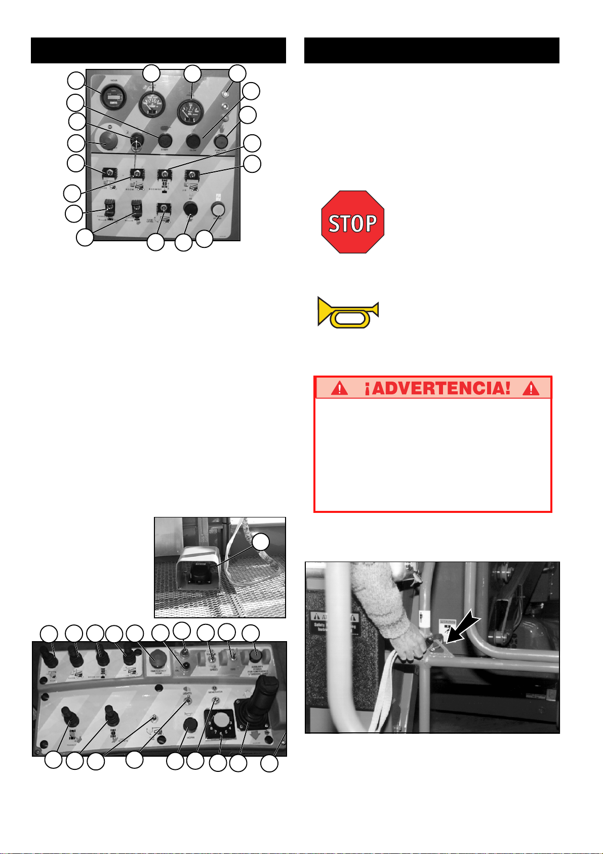
Controles e indicadores
Funcionamiento
1
2
7
8
9
10
13
14
15
Figura 2: Controles del chasis
1. Horómetro
2. Temp. del agua
3. Presión del aceite
4. Automático
5. Estrangulador, luz de la bujía
incandescente
6. Permitida
7. Arranque del motor
8. Interruptor del contacto
9. Parada de emergencia
10. Elevador
11. Extender pluma
12. Elevar brazo
13. Elevar pluma
14. Rotar torreta
15. Rotar la jaula
16. Nivelar la jaula
17. Velocidad alta/baja de la pluma
18. Energía auxiliar
19. Elevador
16
3
4
5
6
11
12
18
17
20. Elevar pluma
21. Extender pluma
22. Elevar brazo
23. Parada de emergencia
24. Rojo-temp. motor
25. Amarillo-inclinación
26. Velocidad alta/baja
27. Gas/prop. seleccionar luz
de bujía incandescente
28. Energía aux.
29. Rotar torreta
30. Rotar la jaula
31. Nivelar la jaula
32. Luz auxiliar
33. Bocina
34. Generador
35. Velocidad pluma
36. Palanca de control/
enclavamiento
37. Interruptor del contacto
38. Interruptor del pedal
Antes de usar la plataforma de trabajo verifique lo siguiente:
Que se ha completado la inspección previa a la puesta en
marcha y de seguridad y que cualquier problema ha sido
corregido.
Que el operador ha sido debidamente formado en el
funcionamiento de la máquina.
Que el área de trabajo está libre de obstrucciones, hoyos,
desniveles o personas en el recorrido de la unidad.
Que la superficie puede soportar la carga de las ruedas.
Consulte las Figuras 1 y 2 para ver la ubicación de los controles.
Parada de emergencia
En una emergencia, presione el botón de parada de emergencia
para detener todas las funciones, cualquiera sea el momento de la
operación.
Bocina
En cualquier momento de la operación, si es necesario dar una
advertencia sonora, presionar el botón de la bocina de servicio.
Si fuera necesario bajo la legislación nacional:
Utilice siempre un arnés de seguridad
autorizado colocado en el punto de anclaje de la
plataforma al desplazar o elevar la máquina (ver
Figura 4).
Colocar solo un arnés de seguridad en cada
punto de anclaje.
Figura 3: Interruptor
del pedal
25
32
24
33
19
29
20
30
21
31
22 23
Figura 4: Controles de la plataforma
34
26
35
27
36
38
28
Figura 5: Punto de anclaje típico
del arnés de seguridad
37
34
Page 35

Arranque del motor
Desde los controles inferiores
1. Ponga el interruptor de llave del chasis en la posición chasis
(CHASSIS).
2. Presione el botón de arranque (START) para encender el motor.
Suéltelo cuando arranque.
3. Si el motor está frío, pulsar y mantener pulsado el botón del
estrangulador mientras se arrancan los motores de gasolina/
propano; pulse el botón de la bujía incandescente y manténgalo
pulsado durante seis segundos antes de arrancar los motores
diesel.
Desde los controles de la plataforma
1. Gire el interruptor de llave del chasis hacia los controles de
plataforma (PLATFORM).
2. Gire completamente el interruptor de la plataforma en el sentido
de las agujas del reloj para arrancar el motor. Suéltelo cuando
arranque.
3. Cuando el motor está frío: pulse y mantenga pulsado el botón del
estrangulador antes de arrancar los motores de gasolina/
propano. Pulse y mantenga pulsado el botón de la bujía
incandescente durante seis segundos antes de arrancar el
motor diesel.
Conducción
Con la pluma baja
1 Gire el interruptor de llave del chasis hacia plataforma
(PLATFORM) y encienda (gire en el sentido de las agujas del
reloj) el interruptor de parada de emergencia del chasis.
2. Monte la plataforma y cierre la guía deslizante.
3. Coloque un arnés de seguridad (si fuera necesario bajo la
legislación nacional) en el punto de anclaje diseñado para ello
en la plataforma. Colocar un solo sujetador en cada punto.
4. Encender el motor.
5. Compruebe que la zona circundante y por encima de la
plataforma de trabajo estén libres de obstrucciones, hoyos,
desniveles, personas en el recorrido y que la superficie sea
capaz de soportar la carga de las ruedas.
6. Pulse el interruptor del pedal (también se puede pulsar el botón
de la palanca de conducción) y mueva la palanca de
conducción hacia adelante (FORWARD) para avanzar y hacia
atrás (REVERSE) para retroceder.
Nota: Cuando se rota la pluma hacia el frente del chasis
(ruedas de dirección hacia atrás) el sentido del
desplazamiento y la dirección se invertirán. Observe las
flechas de colores en el panel de control cerca de la
palanca de conducción y en el chasis. Cuando se mueva la
palanca de conducción las flechas indicarán el sentido de
desplazamiento.
Con la pluma levantada
El desplazamiento con la pluma levantada está restringido a
superficies llanas y firmes solamente.
Con la pluma levantada la máquina se moverá lentamente (0,3 m
[1 pie] por segundo).
Dirección
1. Mientras pulsa el interruptor del pedal, presionar el cambio de
dirección (ubicado arriba de la palanca de control) a la izquierda
para girar a la izquierda y a la derecha para girar a la derecha.
Nota: La dirección no es autocentrante. Las ruedas deben
enderezarse nuevamente usando el interruptor de
dirección.
COLOCACIÓN DE LA PLATAFORMA
La colocación de la plataforma lo más cerca posible del área de
trabajo requiere preparación. Primero, hay que inspeccionar la zona
para encontrar un lugar adecuado para estacionar la máquina. Debe
ser una superficie llana y firme, lo más cerca posible del área de
trabajo. Tenga en cuenta todos los obstáculos elevados y en el
terreno y evítelos.
Una vez que haya desplazado la máquina hasta una superficie llana
y firme, lo más cerca del área de trabajo, siga las instrucciones de
la página 36 para colocar la plataforma lo más cerca posible del
área de trabajo.
Antes de utilizar cualquier función siempre verificar la presencia de
obstrucciones o conductores eléctricos en la zona aledaña.
Controles multifunción
El equipo UpRight AB62 tiene controles multifunción. Esto significa
que la extensión del elevador o la pluma funcionarán a su velocidad
máxima mientras que simultáneamente se acciona la pluma superior,
el brazo, la torreta o se rota la plataforma.
Se puede rotar la torreta durante la conducción con la pluma baja, si
es necesario girar en zonas angostas. Las demás funciones de la
pluma no funcionarán durante la conducción.
Operación de controles inferiores
Todas las funciones de la pluma actuarán a una velocidad fija.
1. Gire el interruptor del chasis hacia controles del chasis
(CHASSIS).
2. Con el motor en marcha, accione los controles de la pluma para
colocar la plataforma.
3. El interruptor alta/baja (HIGH/LOW) selecciona entre una
velocidad máxima y mínima fija de la pluma.
Advertencia: Si suena la alarma de
inclinación, retraiga la pluma y
Deténgase cuando suene
la alarma de inclinación
conduzca la máquina hasta una
superficie plana.
35
Page 36
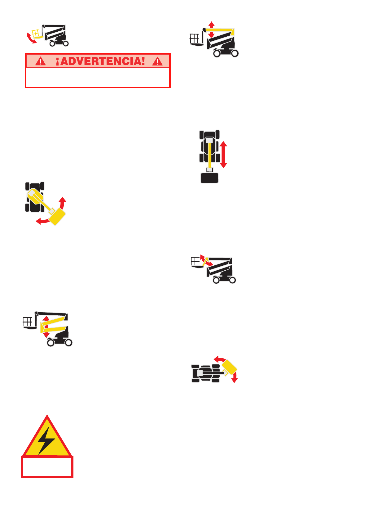
Nivelación de la
plataforma
NO utilice la máquina si la plataforma no se
mantiene nivelada al elevarla.
Nota: La nivelación de la plataforma sólo se puede efectuar
con la pluma en la posición de almacenaje y sólo debe
hacerse para calibrar el sistema de nivelación automático.
1. Ajuste el mando de control de velocidad de funcionamiento en el
valor deseado. Gire el mando en la dirección de las agujas del
reloj para aumentar la velocidad y en la dirección contraria para
disminuirla. Si no está seguro de la velocidad que debe utilizar,
comience lentamente, puede modificar la velocidad mientras
utiliza la función.
2. Mientras que presiona el interruptor del pedal, mueva hacia
adelante el control del nivel de la plataforma para elevarla y
hacia atrás para bajarla. Suelte el control para detener la
nivelación.
Rotación de la torreta
1. Ajuste el mando de control de velocidad de funcionamiento en el
valor deseado. Gire el mando en la dirección de las agujas del
reloj para aumentar la velocidad y en la dirección contraria para
disminuirla. Si no está seguro de la velocidad que debe utilizar,
comience lentamente, puede modificar la velocidad mientras
utiliza la función.
2. Mientras pulsa el interruptor del pedal, gire la palanca de control
de rotación de la torreta hacia la derecha para girar en la
dirección contraria a las agujas del reloj y hacia la izquierda
para girar en la dirección de las agujas del reloj. Suelte el control
para detener la rotación. Observe el área alrededor de la pluma
cuando gire la torreta para evitar cualquier obstáculo.
Elevación del elevador
1. Ajuste el mando de control de velocidad de funcionamiento en el
valor deseado. Gire el mando en la dirección de las agujas del
reloj para aumentar la velocidad y en la dirección contraria para
disminuirla.
2. Mientras que presiona el interruptor del pedal, empuje la palanca
de control del elevador hacia adelante para elevarlo y hacia
atrás para bajarlo. Suelte la palanca de control para detener la
elevación/bajada.
Esta máquina no está aislada.
Proceder según los estándares de
seguridad nacionales y mantener la
distancia prudencial normal al trabajar
LA MÁQUINA NO
ESTÁ AISLADA.
con equipo energizado.
Elevación de la pluma
superior
1. Ajuste el mando de control de velocidad de funcionamiento en el
valor deseado. Gire el mando en la dirección de las agujas del
reloj para aumentar la velocidad y en la dirección contraria para
disminuirla. Si no está seguro de la velocidad que debe utilizar,
comience lentamente, puede modificar la velocidad mientras
utiliza la función.
2. Mientras que presiona el interruptor del pedal, empuje la palanca
de control de la pluma superior hacia adelante para elevarla y
hacia atrás para bajarla. Suelte la palanca de control para
detener la elevación/bajada.
Extensión de la pluma
superior
1. Ajuste el mando de control de velocidad de funcionamiento en el
valor deseado. Gire el mando en la dirección de las agujas del
reloj para aumentar la velocidad y en la dirección contraria para
disminuirla. Si no está seguro de la velocidad que debe utilizar,
comience lentamente, puede modificar la velocidad mientras
utiliza la función.
2. Mientras que presiona el interruptor del pedal, mueva hacia
atrás la palanca de extensión de la pluma para extenderla y
hacia adelante para replegarla. Suelte la palanca de control para
detener la extensión/retracción.
Elevación del brazo
1. Ajuste el mando de control de velocidad de funcionamiento en el
valor deseado. Gire el mando en la dirección de las agujas del
reloj para aumentar la velocidad y en la dirección contraria para
disminuirla. Si no está seguro de la velocidad que debe utilizar,
comience lentamente, puede modificar la velocidad mientras
utiliza la función.
2. Mientras que presiona el interruptor del pedal, empuje la palanca
de control del brazo hacia adelante para elevarlo y hacia atrás
para bajarlo. Suelte la palanca de control para detener la
elevación/bajada.
Rotación de la
plataforma
1. Ajuste el mando de control de velocidad de funcionamiento en el
valor deseado. Gire el mando en la dirección de las agujas del
reloj para aumentar la velocidad y en la dirección contraria para
disminuirla. Si no está seguro de la velocidad que debe utilizar,
comience lentamente, puede modificar la velocidad mientras
utiliza la función.
2. Mientras pulsa el interruptor del pedal, gire la palanca de control
de rotación de la torreta hacia la derecha para girar en la
dirección contraria a las agujas del reloj y hacia la izquierda
para girar en la dirección de las agujas del reloj. Suelte la
palanca para detener la rotación.
36
Page 37
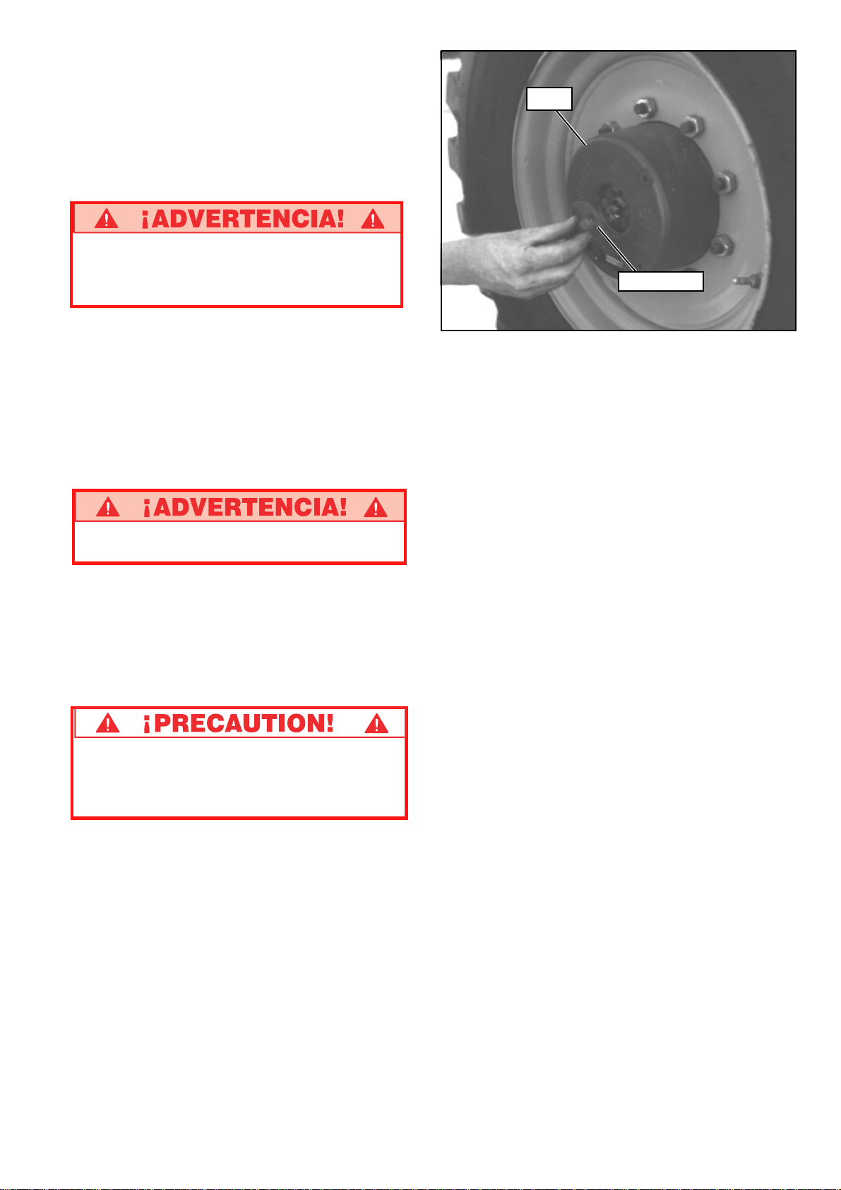
OPERACIÓN DE EMERGENCIA
En el caso de un fallo de la función con suministro de energía, el
conjunto de elevación puede manejarse con la Unidad de energía
auxiliar. Pulse y mantenga pulsado el botón de energía auxiliar y
accione los controles de bajada de forma normal. Importante: Los
botones de parada de emergencia sólo deben utilizarse en
situaciones de verdadera emergencia.
NOTA: El botón de parada de emergencia no funcionará
durante la operación con energía auxiliar.
NUNCA descienda por el conjunto de elevación.
Si los controles no responden, pida a alguien
que se encuentre en el suelo que baje la pluma
manualmente.
REMOLQUE DE EMERGENCIA
Realice lo siguiente sólo cuando la máquina no va a funcionar por sí
misma y es necesario moverla o cargarla en un camión para
transportarla.
1. Verificar que la plataforma esté totalmente baja y que la torre
esté rotada de manera que la plataforma esté detrás de la
máquina.
2. Coloque en las orejetas de amarre delanteros o traseros una
cadena o cable de adecuada resistencia para remolcar la
máquina.
Calce las ruedas mediante topes antes de
desmontar los cubos. La máquina puede rodar.
Cubo
Tapa central
Figura 6: Desmontaje de los cubos
DESPUÉS DE CADA USO DIARIO
1. Asegúrese de que la plataforma esté totalmente abajo.
2. Estacione la máquina en un terreno nivelado, preferentemente
bajo techo, asegurada contra vándalos, niños o usos no
autorizados.
3. Gire la llave de interruptor superior a la posición apagado (OFF),
el interruptor de llave inferior en plataforma (PLATFORM) y
saque las llaves para evitar usos no autorizados.
3. Vea la figura 6 y desajustar los cuatro cubos. Quite dos tornillos
y la tapa central. Vuelva a instalar la tapa central en dirección
opuesta.
4. Antes de mover la máquina, retire los topes. Remolque o utilice
el guinche para ajustar en la posición y vuelva a colocar los
topes.
5. Ajuste los cuatro cubos volviendo a colocar las tapas centrales
de acuerdo la orientación original.
NO mueva la máquina a una velocidad mayor a
5 km/h [3 millas por hora]. Velocidades mayores
dañarán componentes de transmisión y anularán
la garantía.
37
Page 38

Transporte
POR GRÚA
Colóquese lejos de la máquina cuando ésta es
levantada.
Compruebe las especificaciones en la última
página, asegúrese de que la grúa y las eslingas
tengan la capacidad adecuada para levantar el
peso de la unidad.
1. Asegúrese de que la pluma esté totalmente baja y retraída.
2. Coloque correas sólo en las orejetas de amarre del chasis.
Asegúrese de que las correas están bien ajustadas para
mantener la unidad nivelada al levantarla.
POR CAMIÓN O TRÁILER
1. Asegúrese de que la pluma esté totalmente baja y retraída.
2. Eleve el brazo antes de arrancar la máquina o baje la rampa
para evitar que la plataforma contacte con el suelo.
3. Coloque la máquina en la zona de carga del camión o trailer.
4. Cuando utilice un guinche siga las instrucciones para remolcado
de emergencia de la página 37. Enganche el cable del guinche a
las orejetas de amarre delanteras.
No levantar la máquina a una velocidad superior
a 5 km/h [3 millas por hora].
5. Después de utilizar el guinche, asegúrese de que los frenos
están accionados.
6. Asegure la máquina al vehículo de transporte utilizando
cadenas/correas de capacidad de carga adecuada (consulte
las especificaciones en la última página) sujetadas a las
orejetas de amarre del chasis (consulte la Figura 7).
7. Coloque un bloque de madera (20 cm x 10 cm x 75 cm)
[8 pulg. x 4 pulg. x 28 pulg.] debajo de los apoyos, según se
ilustra (consulte la Figura 7).
8. Coloque una correa de trinquete debajo del enrejado del piso de
la plataforma, sobre los apoyos (consulte la Figura 7). Apriete
con firmeza, no ajustar en exceso.
NUNCA eleve la máquina mientras se encuentra
en un camión o trailer.
Bloque de madera
20 cm x 10 cm x 75 cm
(8 pulg. x 4 pulg. x 28 pulg.)
Figura 7: Asegurado de la máquina para el transporte
Anclaje del chasis/
Orejeta de elevación (Típo)
38
Page 39
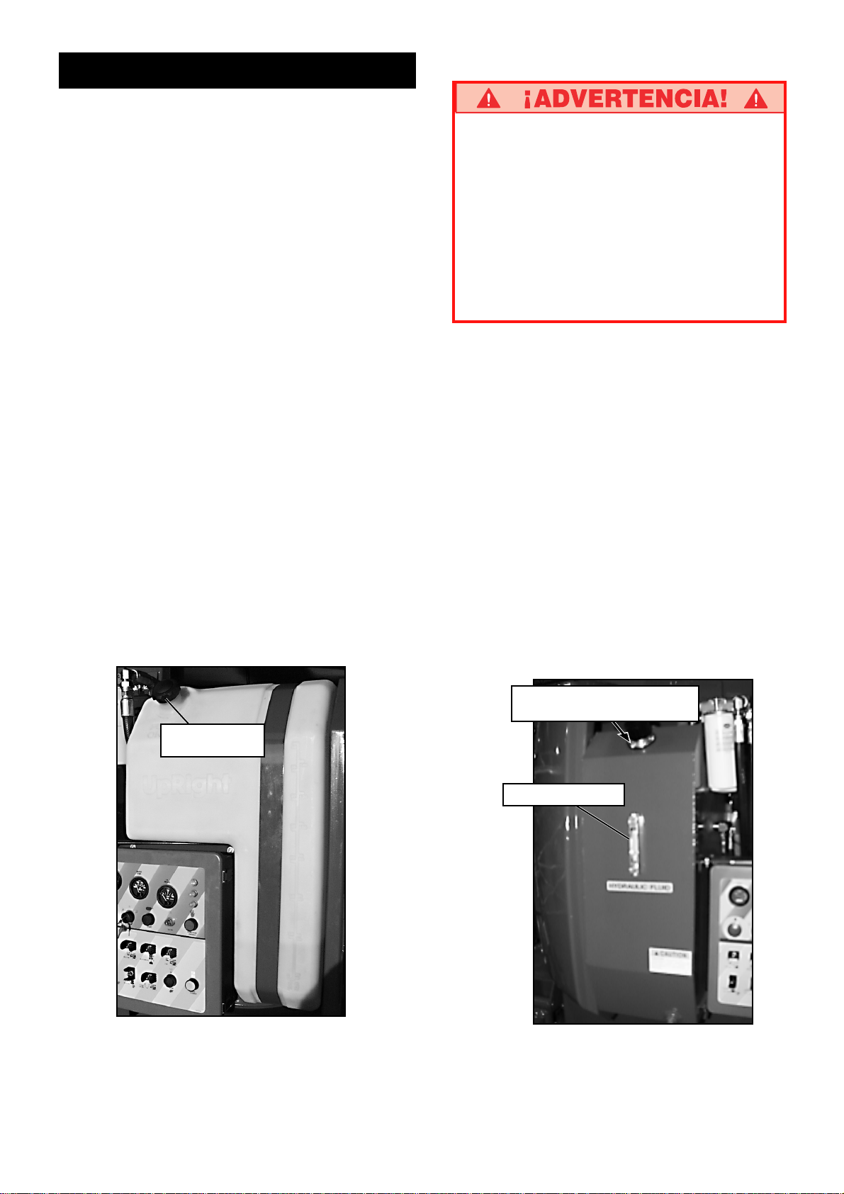
Mantenimiento
REPOSTAJE
Gasolina
1. Abra la cubierta de la torreta izquierda, abra el tapón del tubo de
llenado. (Vea la Figura 8).
2. Llenar solamente con combustible para motores sin plomo.
3. La capacidad total del tanque es de 159 L (42 galones de
EE.UU.).
Diesel
1. Abra la cubierta de la torreta izquierda, abra el tapón del tubo de
llenado. (Vea la Figura 8).
2. Utilice combustible para motores diesel. Utilice combustible diesel
según EN950, no utilice restos o mezclas.
3. La capacidad total del tanque es de 159 L [42 galones de
EE.UU.].
FLUIDO HIDRÁULICO
1. Compruebe el nivel en el indicador del lado derecho dentro del
compartimento del motor con la plataforma completamente
bajada. (Figura 9).
2. Si fuera necesario, llene con fluido hidráulico limpio y compatible
(ISO 46 en verano/ISO 32 en invierno).
3. Abrir la tapa de llenado y respiración y agregar aceite.
4. Vuelva a colocar el tapón.
5. Deshágase adecuadamente del fluido sobrante.
MANTENIMIENTO DE LA BATERÍA
Peligro de mezcla de gases explosivos.
Mantenga la batería lejos de chispas, llama o
humo.
Utilice siempre gafas de seguridad al trabajar
con baterías.
El fluido de la batería es muy corrosivo. Lave
bien los derrames de fluido con agua limpia.
Sustituir siempre las baterías por baterías
UpRight o procedentes de fabricantes
autorizados.
Controle diariamente el nivel del fluido, especialmente si se usa la
plataforma en clima seco y cálido.
Si el nivel de electrolitos es menor de 10 mm (3/8 pulg.) por encima
de las placas, añada sólo agua destilada. NO utilice agua potable ya
que acorta la vida de la batería.
Mantenga limpias las terminales y la parte superior de la batería.
NEUMÁTICOS
La elección de los neumáticos puede afectar la estabilidad de la
máquina. Utilice sólo neumáticos suministrados por UpRight a menos
que lo apruebe el fabricante por escrito. Compruebe a diario la
presión de llenado de los neumáticos. 5,5 bar (80 psi).
LUBRICACIÓN
Consulte el cuadro de lubricación e instrucciones en el manual de
mantenimiento.
Tubo de llenado de
combustible.
Tapón de llenado/respiradero
de aceite hidráulico
Indicador de nivel
Figura 8: Tubo de llenado de combustible
Figura 9: Tapón de llenado/respiradero
de aceite hidráulico
39
Page 40

MANTENIMIENTO RUTINARIO
Usar la tabla siguiente como guía para mantenimiento de rutina. La
inspección y el mantenimiento deben realizarlos personal
entrenado y con experiencia en mecánica y electricidad.
Consulte las instrucciones de mantenimiento en el Manual de
mantenimiento.
Fotocopiar esta página y usar la Tabla de mantenimiento de rutina
como hoja de control al inspeccionar una máquina.
Tabla de mantenimiento rutinario
Referencias de la Tabla de
mantenimiento rutinario
Intervalo
Diario = cada turno (todos los días) o cada ocho horas
30
D
= cada mes (30 días) o cada cincuenta horas
3
M
= cada 3 meses o cada 125 horas
6
M
= cada 6 meses o cada 250 horas
1
A
= cada año o cada 500 horas
2
A
= cada dos años o cada 1000 horas
A = Aceptable
N = No/No aceptable
R = Reparada/Aceptable
COMPONENTE INSPECCIÓN O SERVICIOS INTERVALO A N R
Aceite del Comprobar nivel y estado Diario
motor Comprobar fugas Diario
Cambio de aceite y filtro (Combustible doble) 200 HORAS
Cambio de aceite y filtro (Diesel) 500 HORAS
Sistema de Comprobar nivel combustible Diario
combustible Comprobar fugas Diario
del motor Sustitución filtro de combustible 6M
Comprobar depurador de aire Diario
Batería Comprobar nivel de electrólitos Diario
Limpiar exterior 3M
Limpiar terminales 3M
Refrigerante Comprobar nivel de refrigerante (con motor frío) Diario
del motor Sustitución de refrigerante 3M
Fluido Comprobar nivel del aceite Diario
hidráulico * Cambiar filtro 6M
Drenaje y reemplazo con aceite compatible ISO 46 2A
Sistema Comprobar fugas Diario
hidráulico Comprobar conexiones de mangueras 30D
Comprobar desgaste exterior de mangueras 30D
Sistema Comprobar funcionamiento de anulación de
hidráulico emergencia válvulas y bomba manual Diario
de emergencia Control de funcionamiento de anulador de
emergencia unidad de energía Diario
Controlador Comprobar funcionamiento de todos los controles Diario
Cable Comprobar exterior del cable en busca de
de control estrangulamientos, torsiones o desgaste Diario
Piso y rieles Comprobar par correcto de pasadores Diario
de la Comprobar de grietas las soldaduras Diario
plataforma Comprobar estado de la plataforma Diario
Comprobar estado de puntos de anclaje Diario
Comprobar estado del manual del operador Diario
Neumáticos Comprobar daños Diario
Comprobar que la presión de aire sea 5,5 bar [80 psi] Diario
Control tuercas de anillos de amarre (torsión 123
N·m [90 libras-pies]) 30D
Bomba Limpiar 30D
hidráulica Comprobar fugas en superficies de unión 30D
Comprobar fugas en accesorios de mangueras Diario
Comprobar par de apriete correcto en tornillos de
montaje 30D
Sistema de Comprobar funcionamiento de motor hidráulico Diario
conducción Comprobar fugas en mangueras, conectores y válvulas
hidráulico de bloqueo Diario
COMPONENTE INSPECCIÓN O SERVICIOS INTERVALO A N R
Sistema de Control de apriete correcto de conectores 6M
dirección Lubricar todos los pivotes 30D
Comprobar pérdidas en cilindro de dirección 30D
Comprobar zonas de desgaste en articulación 30D
Comprobar retenes sueltos/perdidos Diario
Conjunto Inspección de grietas estructurales Diario
de elevación Comprobar desgaste en punto de pivotación 30D
Comprobar par apropiado de tornillos de retención de
pasador de pivote 30D
Comprobar deformación de piezas Diario
Chasis Control de deformación o desgaste de las mangueras Diario
Controlar torsión correcta de montaje de componentes 6M
Comprobar de grietas las soldaduras Diario
Torreta Comprobar lubricación y desgaste de corona dentada Diario
Lubricar corona dentada (grasa MoS2) 150H/3M
Apriete Comprobar fugas Diario
Cubos Comprobar nivel del aceite 250H/6M
Cambiar aceite después del período de rodaje 50H/30D
Cambiar aceite (aceite de engranajes SAE 90.) 2000H/2A
Cilindros de Comprobar desgaste de varillas de cilindros 30D
Elevación Comprobar par apropiado de tornillos de retención de
pasador de pivote 30D
Comprobar fugas en juntas 30D
Inspeccionar desgaste de pivotes 30D
Control de apriete correcto de conectores 30 D
Unidad Comprobar y reparar daño por colisión Diario
completa Comprobar par correcto de pasadores 3M
Comprobar corrosión, desmontar y pintar 3M
Lubricar 30D
Etiquetas Comprobar estado, legibilidad o falta de etiquetas,
reemplazar Diario
Informe de mantenimiento
Fecha: ______________________________________
Propietario: __________________________________
Modelo Nº: ___________ Nº de serie: ______________
Realizó mantenimiento:_________________________
Intervalo de mantenimiento: ______________________
*ISO grado 46, para temperaturas superiores a 32 °F (0 °C).
í
*Para climas más fro
*temperaturas de 0 °F (-17 °C) hasta 32 °F (0 °C).
*ISO grado 15, para temperaturas por debajo de 0 °F (-17 °C).*
s: ISO grado 32, para rango de
40
Page 41

Especificaciones*
ESPECIFICACIONES AB62 4WD DIESEL AB62 4WD GASOLINA
Altura
Altura máxima de trabajo 20,7 m [68 pies] 20,7 m [68 pies]
Altura máxima de la plataforma 18,9 m [62 pies] 18,9 m [62 pies]
Altura del paso de la plataforma 343 mm [13,5 pulg.] 343 mm [13,5 pulg.]
Altura arriba y superior 9,1 m [30 pies] 9,1 m [30 pies]
Altura en conducción 18,9 m [62 pies] 18,9 m [62 pies]
Alcance horizontal 10,7 m [35 pies] 10,7 m [35 pies]
Rotación de la torreta 360° continuo 360° continuo
Rotación de la plataforma 180° 180°
Oscilación de la cola (recogida) 0 0
Longitud del brazo 1,9 m [6 pies 4 pulg.] 1,9 m [6 pies 4 pulg.]
Arco del brazo 140° 140°
Radio de giro interno 2,5 m [8 pies] 2,5 m [8 pies]
Radio de giro externo 5,5 m [18 pies] 5,5 m [18 pies]
Velocidad de conducción 6,8 km/h [4,25 millas/hora] (alta) 6,8 km/h [4,25 millas/hora] (alta)
(pluma recogida, desplazamiento) 2,6 km/h [1,6 millas/hora] (baja) 2,6 km/h [1,6 millas/hora] (baja)
Velocidad de conducción (elevado) 0,96 km/h [0,6 millas/hora] 0,96 km/h [0,6 millas/hora]
Gradabilidad 22° [40%] 22° [40%]
Dimensiones (pluma recogida)
Tamaño de la plataforma 1 m x 1,8 m [39 pulg. x 72 pulg.] 1 m x 1,8 m [39 pulg. x 72
pulg.] Plataforma opcional de 2,4 m (8 pies) 1 m x 2,4 m [39 pulg. x 96
pulg.] 1 m x 2,4 m [39 pulg. x 96 pulg.]
Altura de la baranda 1,14 m [45 pulg.] 1,14 m [45 pulg.]
Tabla de pie 0,15 m [6 pulg.] 0,15 m [6 pulg.]
Capacidad máxima de la plataforma 227 kg [500 lbs.] 227 kg [500 lbs.]
Número máximo de ocupantes 2 2
Peso 10 614 kg [23 400 lbs.] 10 614 kg [23 400 lbs.]
Altura total 2,5 m [8 pies 2 pulg.] 2,5 m [8 pies 2 pulg.]
Longitud total 8,2 m (or 7,2 m min.) 8,2 m (or 7,2 m min.)
[27 pies o 23 pies 6 pulg. min.] [27 pies o 23 pies 6 pulg. min.]
Ancho total 2,3 m [7 pies 7,5 pulg.] 2,3 m [7 pies 7,5 pulg.]
Distancia entre ejes 2,6 m [8 pies 6 pulg.] 2,6 m [8 pies 6 pulg.]
Altura desde suelo 0,46 m (centro) 0,32 m (eje) 0,46 m (centro) 0,32 m (eje)
[18 pulg. (centro), 12,5 pulg. (eje)] [18 pulg. (centro), 12,5 pulg. (eje)]
Fuente de potencia Perkins 704-30 GM 3,0 L
Voltaje del sistema 12 V CC 12 V CC
Presión hidráulica máxima 345 bar [5000 psi] 345 bar [5000 psi]
Mandos Proporcional eléctrico Proporcional eléctrico
Neumáticos 19x15 NHS - 14 capas nominales 19x15 NHS - 14 capas nominales
*Especificaciones sujetas a modificación sin aviso previo.
Ver información sobre componentes y mantenimiento en el Manual de
mantenimiento.
ESQUEMA DEL RADIO DE ALCANCE TOTAL
DIMENSIONES EN METROS
41
Page 42

Hydraulic Schematic, AB62 - 104048-000
ENGLISH FRANCAIS GERMAN SPANISH
1 Cylinder Vérin Linder Cilindro
2 Motor Moteur Motor Motor
3 Pump Pompe Pumpe Bomba
4 Filter Filtre Filter Filtro
5 Valve Soupape Ventil Válvula
6 Relief Valve Soupape de décharge Überdruckventil Válvula de alivio
7 Counterbalance Valves Soupapes d'équilibrage Ausgleichsventile Válvulas de contrapeso
8 Flow Divider Vanne Distributrice Strömungsteiler Divisor de Flujo
9 Accumulator Accumulateur Akkumulator Acumulador
10 Orofice Orofice Drosselblende Oroficio
42
Page 43

1
2
2
1
7
1
1
1
7
2
2
2
1
1
1
7
1
777
1
6
1
1
7
7
2
7
10
7
5
10
8
5
5
7
7
7
8
5
5
5
5
5
5
5
7
5
5
6
5
6
9
5
5
5
3
3
3
4
4
3
4
4
4
Hydraulic Schematic; AB62 (104048-000)
Schéma hydraulique; AB62 (104048-000)
Hydraulikschaltplan;
Esquema hidráulico; AB62 (104048-000)
AB62 (104048-000)
Page 44

Electrical Schematic, AB62 - 104049-002-1,-2
ENGLISH FRANÇAIS GERMAN SPANISH
1 Switch Interrupteur Schalter Interruptor
2 E-Stop Arrêt d’urgence Notaus-Taster Parada de emergencia
3 Relay Relais Relais Relé
4 Lamp Ampoule Leuchte Lámpara
5 Tilt Alarm Alarme d’inclinaison Neigungswarnung Alarma de inclinación
6 Diode Diode Diode Diodo
7 Circuit Breaker Coupe-circuit Schutzschalter Disyuntor
8 Hour Meter Horomètre Schlaglochschutz Horómetro
9 Solenoid Solénoïde Magnetventil Solenoide
10 Horn Avertisseur sonore Horn Bocina
11 Motor Moteur Motor Motor
12 Pump Pompe Pumpe Bomba
13 Isolator Sectionneur Trennschalter Aislador
14 Battery Batterie Batterie Batería
15 Actuator Actionneur Antrieb Actuador
1 6 Timer Temporisateur Zeitauslöser Contador de tiempo
17 Controller Boîtier de commande Steuerpult Controlador
18 Transmitter Transmetteur Transmitter Transmisor
19 Sensor Capteur Sensor Sensor
21 175A fuse Fusible, 175A Sicherung 175 A Fusible de 175 A
22 Temperature Gauge Thermomètre Temperaturanzeigegerät Indicador de temperatura
23 Oil Pressure Gauge Manomètre à huile Öldruckanzeige Indicador de presión de
aceite
44
Page 45

1
10
19
9
9
9
9
9
9
9
9
9
9
9
9
9
9
9
9
21
11
3
1
14
14
9
9
12
9
9
9
9
13
15
1
20
6
19
11
19
9
6
16
3
17
Electrical Schematic; AB62 (104049-002-1)
Schéma de câblage; AB62 (104049-002-1)
Elektrischer Schaltplan
AB62 (104049-002-1)
Esquema eléctrico; AB62 (104049-002-1)
Page 46

4
4
18
1
1
1
17
1
2
1
3
1
1
1
4
1
1
1
4
1
5
1
1
7
7
17
3
3
3
3
3
1
7
6
1
2
1
1
1
1
6
1
6
3
3
6
1
1
1
1
1
1
6
22
3
22
8
6
3
1
Electrical Schematic; AB62 (104049-002-2)
Schéma de câblage; AB62 (104049-002-2)
Elektrischer Schaltplan;
AB62 (104049-002-2)
Esquema eléctrico; AB62 (104049-002-2)
Page 47

47
Page 48

FOR MORE INFORMATION
USA Local Distributor:
TEL: (1) 209-891-5200
FAX: (1) 209-896-9012
PARTSFAX: (1) 209-896-9244
1775 Park St., Selma, CA 93662
http://www.upright.com
EUROPE
TEL: (353) 1-285-3333
FAX: (353) 1-284-0015
Pottery Road, Dun Laoire, Ireland
ÉTATS-UNIS Distributeur local :
TÉL. : (1) 209-891-5200
TÉLÉC. : (1) 209-896-9012
TÉLÉC. (PIÈCES) : (1) 209-896-9244
1775 Park St., Selma, CA 93662
http://www.upright.com
EUROPE
TÉL : (353) 1-285-3333
TÉLÉC. : (353) 1-284-0015
Pottery Road, Dun Laoire, Ireland
USA Ihr Ortsvertrieb:
TEL: (1) 209-891-5200
FAX: (1) 209-896-9012
Fax für Ersatzteile: (1) 209-896-9244
1775 Park St., Selma, CA 93662
http://www.upright.com
EUROPA
TEL: (353) 1-285-3333
FAX: (353) 1-284-0015
Pottery Road, Dun Laoire, Ireland
USA Distribudor local:
TÉLÉFONO: (1) 209-891-5200
FACSÍMIL : (1) 209-896-9012
FACSÍMIL PARA REPUESTOS: (1) 209-896-9244
1775 Park St., Selma, CA 93662
http://www.upright.com
EUROPA
TÉLÉFONO: (353) 1-285-3333
FACSÍMIL : (353) 1-284-0015
Pottery Road, Dun Laoire, Ireland
104044-020
01/00 U
 Loading...