

Page 1
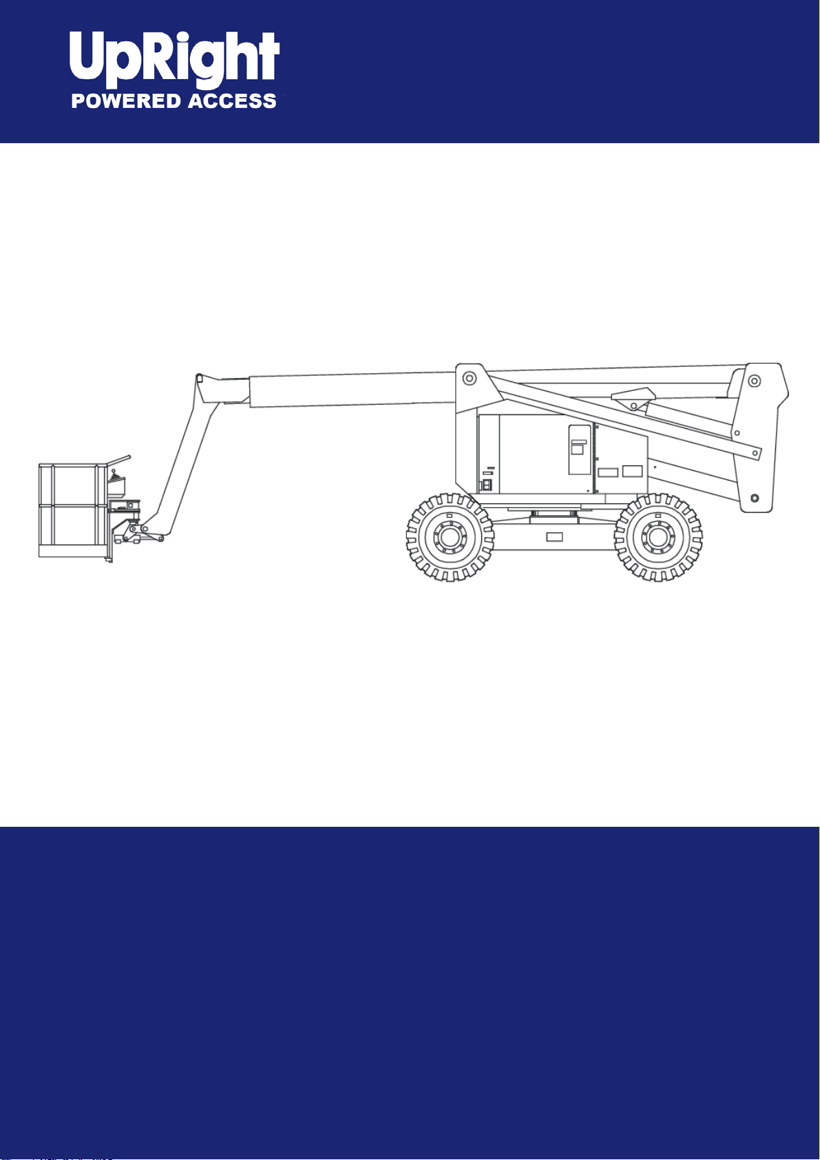
AB60JRT
Operator Manual
Betriebsanleitung
Manual del Usuario
Manuale d’Uso
Bedieningshandleiding
Manual part number 508321-001(EN)
Bestellnummer 508321-001(DE)
El número de referencia para el manual es el 508321-001(ES)
Manuale Ricambi Numero 508321-001(IT)
Handboek onderdeelnummer 508321-001(NL)
September 08
Page 2

Page 3

Table of Contents
Declaration of Conformity ...........................................2
Safety Rules ...............................................................3
Introduction .................................................................4
Component Identifi cation ............................................4
Special Limitations......................................................5
Platform Capacity ....................................................5
Manual Force ..........................................................5
Platform Overload Sensing System ........................5
Beaufort Scale .........................................................5
Controls and Indicators...............................................6
Battery Disconnect Switch ......................................6
Lower Controls and Indicators ................................6
Upper Controls and Indicators ................................6
Pre-Operation Safety Inspection ................................7
System Function Inspection .......................................8
Operation ....................................................................9
Cold Weather Start-Up ............................................9
Hydraulic System Cold Weather Warm-Up ............9
Hydraulic System Warm-up Switch .........................9
Manually Warming The Hydraulic System ..............9
Preparing for Operation .........................................10
Lower Controls ......................................................10
Upper Controls ......................................................10
Boom Operation ....................................................10
Driving and Steering ..............................................10
Drive Speeds .........................................................11
Motion Warning Alarm ...........................................11
AC Generator ........................................................11
Air Line ..................................................................12
Driving Lights ........................................................12
Platform Work Lights .............................................12
Table of Contents
Emergency Lowering ............................................12
Riser Boom ...........................................................12
Main Boom ............................................................13
After Use Each Day ...............................................13
Transporting the Machine .........................................14
Preparing for Transportation .................................14
By Crane ...............................................................14
By Truck ................................................................14
Maintenance .............................................................15
Hydraulic Fluid ......................................................15
Check Hydraulic Fluid ...........................................15
Engine ...................................................................15
Oil Level ................................................................15
Battery Maintenance .............................................15
Inspection and Maintenance Schedule.....................16
Daily Preventative Maintenance Checklist ...............17
Preventative Maintenance Report .........................17
Decal Location ..........................................................18
Specifi cations ...........................................................20
Aerial Platform .......................................................20
Platform .................................................................20
Function Speed .....................................................20
Drive System .........................................................20
Tires ......................................................................20
Electrical System ...................................................20
Hydraulic System ..................................................20
Engine ...................................................................20
Fuel Tank Capacity ................................................20
Ambient Air Temperature Operating Range ..........20
Maximum Wind Speed ..........................................20
Vibration ................................................................20
Sound Threshold ...................................................20
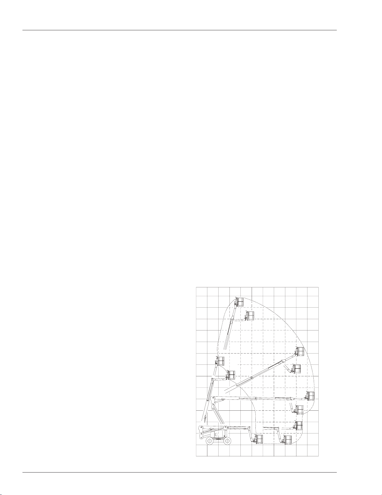
Working Envelope .................................................20
AB60JRT 1
Page 4

EC DECLARATION OF CONFORMITY
FOR MACHINERY
MACHINERY:
Powered Aerial Platform known as:
Type: SNORKEL AB60J (Upright AB60JRT)
Serial Number:
The machine specified above conforms to the following provisions:
Machinery directive 98/37/EC (using document EC Community Legislation on Machinery and taking
guidance from EN280:2001 + Amendment A1:2004)
Council Directive 89/336/EEC on Electromagnetic Compatibility as amended by 93/68/EEC and 92/31/EC
Council Directive 73/23/EEC on Low Voltage Equipment Safety as amended by 93/68/EE
Council Directive 2000/14/EC on Noise Emission in the Environment by Equipment for use Outdoors
As performed in accordance with EN 3744:1995
Measured sound power level
Guaranteed sound power level 100dB
E. C. Type Examination Certificate No:
91 dB Min
100dB Max
Note: Modification of the specified unit renders this declaration invalid
2 AB60JRT
Page 5
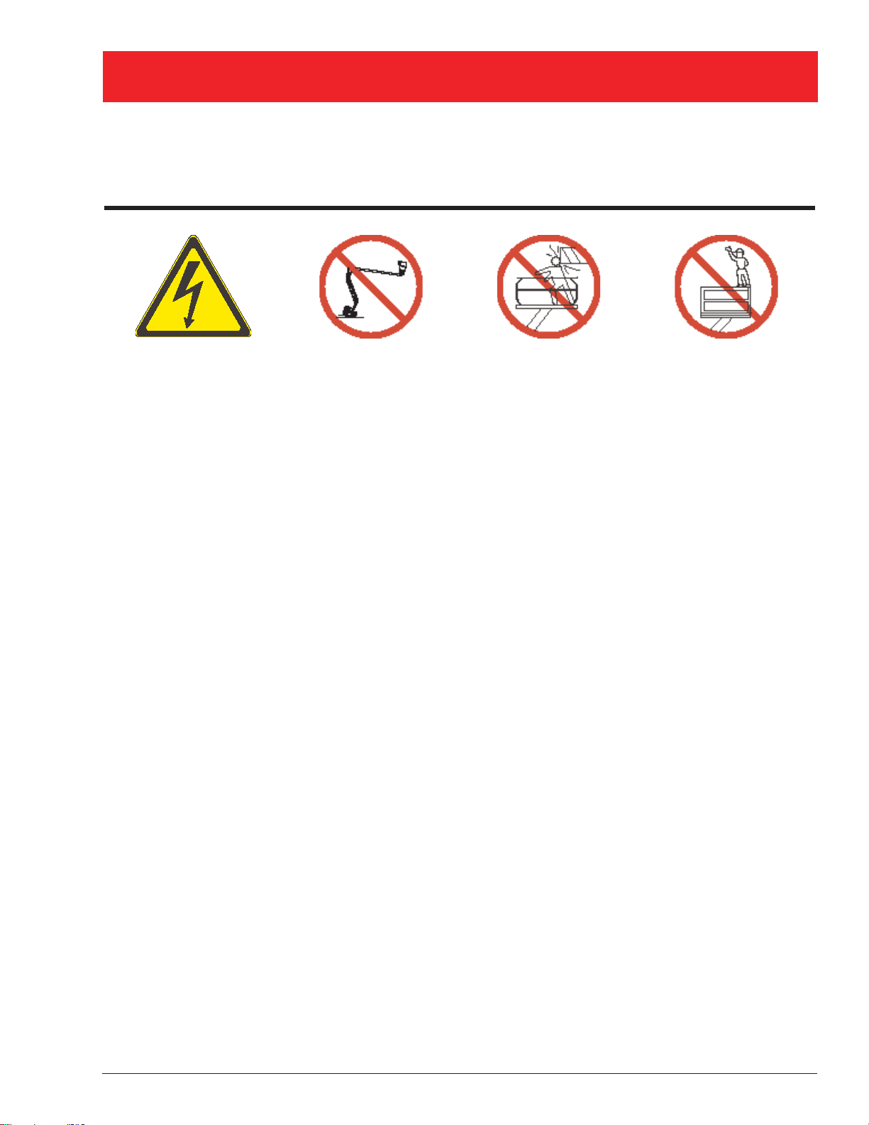
SAFETY RULES
AWarning
All personnel shall carefully read, understand and follow all safety rules and operating instructions
before operating or performing maintenance on any UpRight aerial work platform.
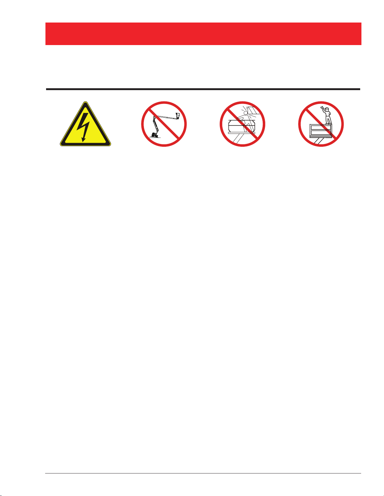
Electrocution Hazard Tip Over Hazard Collision Hazard Fall Hazard
8
3
B
A
t
h
g
i
R
p
U
THIS MACHINE IS
NOT INSULATED!
NEVER elevate the platform
or drive the machine while
elevated unless the machine
is on a firm, level surface
NEVER position the platform
without first checking for
overhead obstructions or
other hazards.
NEVER climb, stand, or sit
on platform guardrails or
midrail.
USE OF THE AERIAL WORK PLATFORM: This aerial work platform is intended to lift persons and his tools as well as the
material used for the job. It is designed for repair and assembly jobs and assignments at overhead workplaces (ceilings,
cranes, roof structures, buildings etc.). Uses or alterations to the aerial work platform must be approved by UpRight.
THIS AERIAL WORK PLATFORM IS NOT INSULATED! For this reason it is imperative to keep a safe distance from live
parts of electrical equipment!
Exceeding the specifi ed permissible maximum load is prohibited! See “Platform Capacity” on page 5 for details.
The use and operation of the aerial work platform as a lifting tool or a crane is prohibited!
NEVER exceed the manual force allowed for this machine. See “Manual Force” on page 5 for details.
DISTRIBUTE all platform loads evenly on the platform.
NEVER operate the machine without fi rst surveying the work area for surface hazards such as holes, drop-offs, bumps, curbs,
or debris; and avoiding them.
OPERATE machine only on surfaces capable of supporting wheel loads.
NEVER operate the machine when wind speeds exceed this machine’s wind rating. See “Beaufort Scale” on page 5 for details.
Do not operate the aerial platform in windy or gusty conditions. Do not add anything to the aerial platform that will increase the
wind loading such as billboards, banners, flags, etc.
IN CASE OF EMERGENCY push EMERGENCY STOP switch to deactivate all powered functions.
IF ALARM SOUNDS while platform is elevated, STOP, carefully lower platform. Move machine to a fi rm, level surface.
Climbing up the railing of the platform, standing on or stepping from the platform onto buildings, steel or prefab concrete
structures, etc., is prohibited!
Dismantling the entry gate or other railing components is prohibited! Always make certain that the entry gate is closed!
It is prohibited to keep the entry gate in an open position when the platform is raised!
To extend the height or the range by placing of ladders, scaffolds or similar devices on the platform is prohibited!
NEVER perform service on machine while platform is elevated without blocking elevating assembly.
INSPECT the machine thoroughly for cracked welds, loose or missing hardware, hydraulic leaks, loose wire connections, and
damaged cables or hoses before using.
VERIFY that all labels are in place and legible before using.
NEVER use a machine that is damaged, not functioning properly, or has damaged or missing labels.
To bypass any safety equipment is prohibited and presents a danger for the persons on the aerial work platform and in its
working range.
NEVER charge batteries near sparks or open fl ame. Charging batteries emit explosive hydrogen gas.
Modifi cations to the aerial work platform are prohibited or permissible only at the approval by UpRight.
AFTER USE, secure the work platform from unauthorized use by turning the keyswitch off and removing key.
The driving of MEWP’s on the public highway is subject to national traffi c regulations.
Certain inherent risks remain in the operation of this machine despite utilizing proper design practices and safeguarding.
Harness attachment points are provided in the platform and the manufacturer recommends the usage of a fall restraint
harness, especially where required by national safety regulations.
Care must be taken to ensure that the machines meets the requirements of stability during use, transportation, assembly,
dismantling when out of service, testing, or foreseeable breakdowns.
In the event of an accident or breakdown see “Emergency Lowering” on page 12, do not operate the aerial platform if it is
damaged or not functioning properly. Qualifi ed maintenance personnel must correct the problem before putting the aerial
platform back into service.
AB60JRT 3
Page 6
Introduction
Introduction
This manual covers the AB60JR T Aerial Work Platform.
This manual must be stored on the machine at all
times.
Read, Understand and follow all safety rules and op-
erating instructions before attempting to operate the
machine.
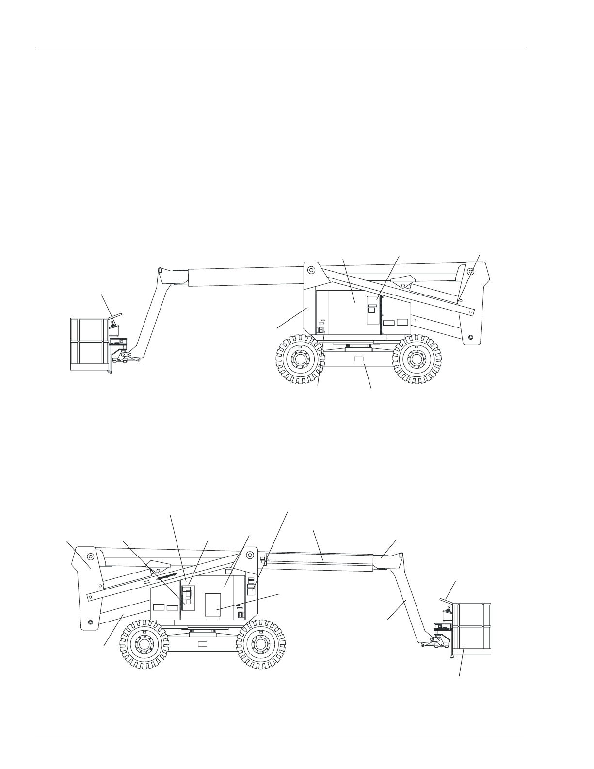
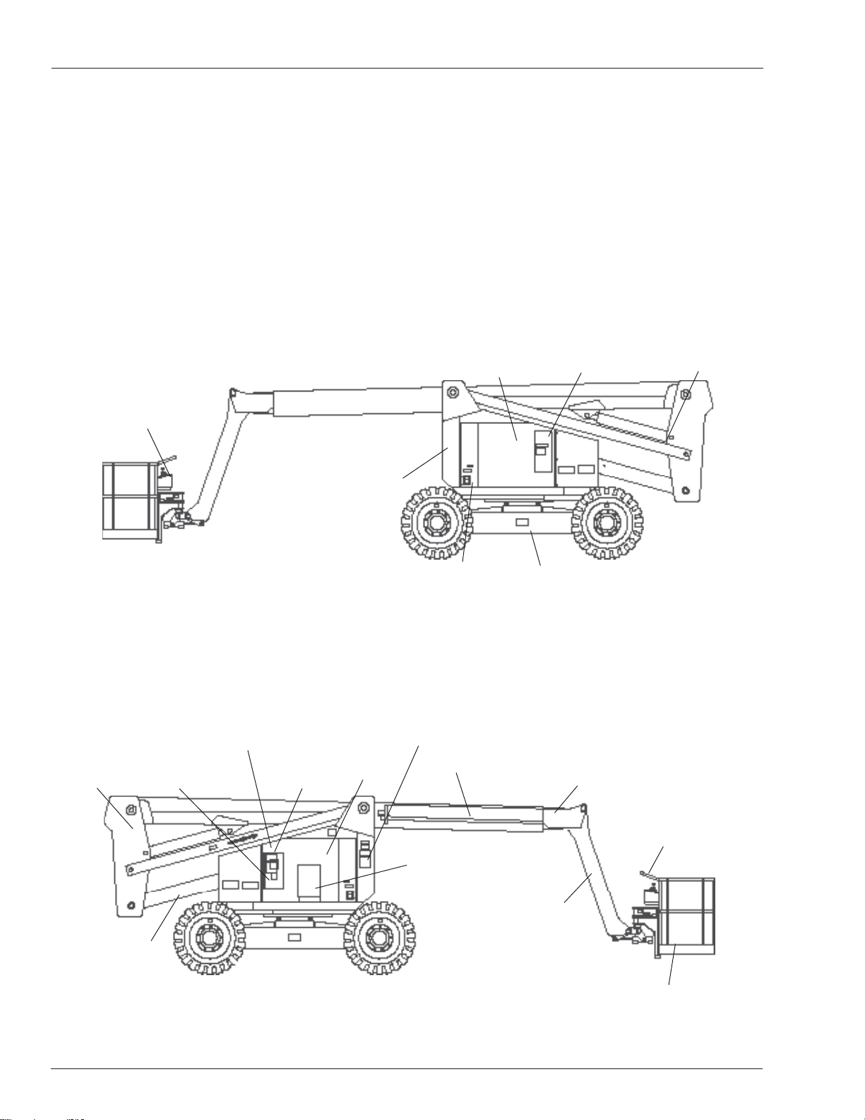
Component Identifi cation
Upper Controls
Emergency
Lowering Valve
When contacting UpRight for service or parts information,
be sure to include the MODEL and SERIAL NUMBERS
from the equipment nameplate. Should the nameplate
be missing, the SERIAL NUMBER is also stamped next
to the right hand Rear Drive Motor Cover.
Fuel Tank
Hydraulic Fluid
Tank
Emergency
Lowering Valve
Floating
Turret
Riser
Boom
Lower
Controls
Battery Disconnect Switch
Battery
Engine
Hydraulic Fluid
Right Side
Nameplate
Location
Operator’s
Manual
Filter
Main Boom
Chassis
Tip Boom
Boom
Steer Wheels
Platform
Jib
Steer Wheels
Platform
Foot Switch
Left Side
4 AB60JRT
Page 7

Special Limitations
Special Limitations
Travel with the platform raised is limited to creep speed
range. Elevating the platform is limited to firm, level
surfaces only .
ADanger
The elevating function shall ONLY be used when the
work platform is level and on a firm surface.
The work platform is NOT intended to be driven over
uneven, rough, or soft terrain.
Platform Capacity
Two people and tools may occupy the platform. The maximum platform capacity for the aerial platform is stated in
the “Specifications” on page 20.
ADanger
DO NOT exceed the maximum platform capacity or
the platform occupancy limits for this machine.
Manual Force
Manual force is the force applied by the occupants to
objects such as walls or other structures outside the
work platform.
The maximum allowable manual force is limited to 200N
(45 lbs) of force per occupant, with a maximum of 400 N
(90 lbs) for two occupants.
ADanger
DO NOT exceed the maximum amount of manual
force for this machine.
The system will remain in error mode until the excess
load is removed from the platform and the emergency
stop button or start switch is cycled off and back on,
resetting the system. At that time, the machine functions
are operational.
ACaution
The emergency power system is for emergency lowering and stowing only. The length of time the pump
can be operated depends on the capacity of the battery. Do not use this system for normal operation.
If the platform overload sensing system is tripped while
operating the machine or if the system is in error mode
and can not be reset, the emergency power system may
still be used for emergency machine operation.
ADanger
The aerial platform can tip over if it becomes unstable.
Death or serious injury will result from a tip-over accident. Do not exceed the capacity values indicated
on the platform rating placard.
The overload sensing system is not active when the
machine is being driven with the booms in the stowed
position. This allows the machine to be driven without
the system sensing an overload due to rough ground
conditions.
To eliminate repeated tripping of the system during machine operation, there is a five second delay in machine
functions following:
starting the engine.
•
Platform Overload Sensing System
All functions are stopped from the upper and lower controls, when the platform overload limit is exceeded. The
horn will sound intermittently and the platform overload
light will blink until the excess load is removed from the
platform. At that time, the machine functions are again
operational.
If the platform becomes significantly overloaded, or if an
upward force on the platform exceeds approximately 2225
N (500 lbs), the system will enter into error mode, stopping
all functions from the upper and lower controls. The horn
will then sound constantly and the overload light will stay
illuminated at the upper and lower controls.
BEAUFORT
RATING
3 3,4~5,4 12,25~19,4 11.5~17.75 7.5~12.0 Papers and thin branches move, fl ags wave.
4 5,4~8,0 19,4~28,8 17.75~26.25 12.0~18 Dust is raised, paper whirls up, and small branches sway.
5 8,0~10,8 28,8~38,9 26.25~35.5 18~24.25
6 10,8~13,9 38,9~50,0 35.5~45.5 24.5~31
7 13,9~17,2 50,0~61,9 45.5~56.5 31.~38.5 Whole trees sway. It is diffi cult to walk against the wind.
m/s km/h ft/s mph
WIND SPEED
Figure 1 – Beaufort Scale
placing the drive/boom selector switch in the boom
•
position when the main boom is below horizontal and
fully retracted.
removing excess load from the platform.
•
Beaufort Scale
Never operate the machine when wind speeds exceed
12.5 m/s (28mph) [Beaufort scale 6]. Refer to Figure 1.
GROUND CONDITIONS
Shrubs with leaves start swaying. Wave crests are apparent in ponds
or swamps.
Tree branches move. Power lines whistle. It is diffi cult to open an
umbrella.
AB60JRT 5
Page 8
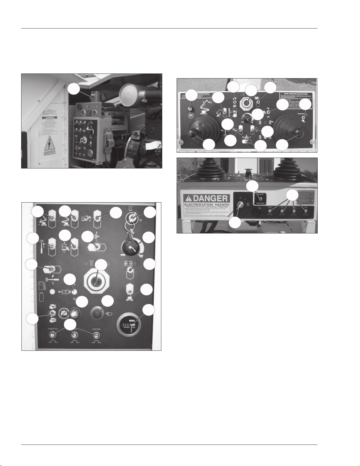
Controls and Indicators
Controls and Indicators
The operator shall know the location of each control and
indicator and have a thorough knowledge of the function
and operation of each before attempting to operate the
machine.
1
Figure 2 – Battery Disconnect Switch
1. Battery Disconnect Switch
14. Engine/emergency power switch
15. Throttle switch
16. Hydraulic warm-up switch (option)
17. Circuit breaker reset buttons
18. Platform overload light
19. Hour meter
34
23
24
25
26
33
20
35
32
27
30
31
29
28
22
36
7
9
6
15
Figure 3 – Lower Controls and Indicators
2. Emergency stop button
3. Control selector switch
4. Start switch
5. Ground operation switch
6. Rotation switch
7. Riser boom elevation switch
8. Main boom elevation switch
9. Boom extension switch
10. Jib articulation switch
1 1. Boom speed knob
12. Platform level switch
13. Platform rotate switch
8
12
16
17
18
10
13
2
4
11
14
5
19
3
21
Figure 4 – Upper Controls and Indicators
20. Emergency stop button
21. Start switch
22. Drive/boom selector switch
23. Boom joystick
24. Riser boom elevation switch
25. Boom extension switch
26. Jib articulation switch
27. Boom speed knob
28. Drive joystick
29. Drive range switch
30. Platform level switch
31. Platform rotate switch
32. Engine/emergency power switch
33. Throttle switch
34. Platform overload light
35. Machine/generator switch
6 AB60JRT
Page 9

Pre-Operation Safety Inspection
Pre-Operation Safety Inspection
Note
Carefully read, understand and follow all safety rules,
operating instructions, labels and National Safety Instructions/Requirements. Perform the following steps each
day before use.
1. Open the turntable covers and inspect for damage,
fluid leaks or missing parts.
2. Check the level of the hydraulic fluid with the platform fully lowered. The fluid level must be between
the full and add marks as viewed on the sight glass.
Add recommended hydraulic fluid if necessary . See
“Specifications” on page 20.
3. Check that the fluid level in the batteries is correct.
See “Battery Maintenance” on page 15.
4. Check that all guardrails are in place and all fasteners
are properly tightened.
5. Inspect the machine thoroughly for cracked welds
and structural damage, loose or missing hardware,
hydraulic leaks, damaged control cable and loose
wire connections.
AB60JRT 7
Page 10

System Function Inspection
System Function Inspection
Refer to “Controls and Indicators” on page 6 for the locations of various controls and indicators.
AWarning
STAND CLEAR of the work platform while performing
the following checks.
Before operating the machine, survey the work area
for surface hazards such as holes, drop-offs, bumps
and debris.
Check in ALL directions, including above the work
platform, for obstructions and electrical conductors.
1. Move the machine, if necessary , to an unobstructed
area to allow for full elevation.
2. Pull the Lower Control Emergency Stop Switch to the
ON position.
3. Pull the Upper Control Emergency Stop Switch to the
ON position.
4. Visually inspect the elevating assembly , lift cylinder,
cables, and hoses for cracked welds and structural
damage, loose hardware, hydraulic leaks, loose wire
connections, and erratic operation. Check for missing
or loose parts.
5. Test each machine function (Lift, Slew, Telescope)
from the lower control station by holding the ground
operation switch up while operating the control toggle
switches (ref: Figure 3 on page 6).
6. Test the engine/emergency power switch for proper
operation.
7. Push the Lower Control Emergency Stop Button to
check for proper operation. All machine functions
should be disabled. Pull the Lower Control Emergency Stop Button outward to resume.
8. Enter the platform and close the gate.
9. Check that the route is clear of obstacles (persons,
obstructions, debris), is level, and is capable of supporting the wheel loads.
10. Test each machine function (Drive, Lift, Slew, Telescope, Platform Rotate, Platform Level) from the
upper control station by stepping on the platform foot
switch and operating the function controls (ref: Figure
4 on page 6).
11. Push the Upper Control Emergency Stop Button to
check for proper operation. All machine functions
should be disabled. Pull the Upper Control Emergency Stop Button outward to resume.
8 AB60JRT
Page 11

Operation
Operation
The aerial platform may be operated from either the lower
or upper controls.
ADanger
The aerial platform is not electrically insulated. Death
or serious injury will result from contact with, or inadequate clearance from, an energized conductor.
Do not go closer than the minimum safe approach
distance as defined by national safety regulations.
Pinch points may exist between moving components.
Death or serious injury will result from becoming
trapped between components, buildings, structures
or other obstacles. Make sure there is sufficient clearance around the machine before moving the chassis,
booms, or platform. Allow sufficient room and time
to stop movement to avoid contact with structures
or other hazards.
The aerial platform can tip over if it becomes unstable.
Death or serious injury will result from a tip-over accident. Operate the aerial platform on a firm, flat, level
surface. Avoid travel speeds and/or rough terrain that
could cause sudden changes in platform position. Do
not drive or position the aerial platform for elevated
use near any drop-off, hole, slope, soft or uneven
ground, or other tip-over hazard.
The engine may be equipped with a block heater. Plug the
heater cord in eight hours before starting the engine. The
heater will warm the engine block to make cold weather
starting easier.
Unplug the power cord before starting the engine.
Hydraulic System Cold Weather Warm-Up
Some engines may have a hydraulic fluid warm-up system that will automatically warm the fluid upon activating
the warm-up switch. The hydraulic fluid may also be
warmed manually if the machine is not equipped with the
optional warm-up system.
ACaution
Not all hydraulic fluid is suitable to use in the hydraulic system. Some have poor lubricating characteristics and can increase component wear. Only use
hydraulic fluid as recommended.
Use cold weather hydraulic oil as recommended in the
machine General Specifications in temperatures of -12°C
(10°F) or below.
Hydraulic System Warm-up Switch
This system may be used to warm the hydraulic fluid when
the ambient temperature is below 0°C (32°F) and boom
movement is sluggish because of cold fluid.
The platform rated work load is the total weight of the personnel and equipment that may be lifted in the platform.
The work loads are stated on the platform rating placard
mounted at the rear of the platform.
ADanger
The aerial platform can tip over if it becomes unstable.
Death or serious injury will result from a tip-over accident. Do not exceed the capacity values indicated
on the platform rating placard.
Capacity values indicate the rated lifting capacity and do
not indicate aerial platform stability .
The operator bears ultimate responsibility for ensuring
that the aerial platform is properly set up for the particular
conditions encountered.
Cold Weather Start-Up
If the ambient temperature is 0°C (32°F) or below, the
engine and hydraulic system oil may need to be warmed
before operation. Do not operate the engine at more than
a fast idle until the engine and hydraulic oil has had a
chance to warm. The engine may be equipped with an
optional cold weather start kit.
Cold, thick hydraulic oil does not flow well and may cause
delay in response to control movement and improper voltage output of the AC generator. Cold oil may also cause
cavitation and pump damage. The hydraulic system may
be equipped with an optional cold weather warm-up kit.
There may be a toggle switch for the warm-up system
on the lower control panel and/or one on the left side of
the upper control panel.
The engine must be running and the switch used to turn
the system on must be at the same location that the engine was started. For example, if the engine was started
from the lower controls, the warm-up switch at the lower
controls must be used for the system to operate.
To operate the warm-up system:
1. Start the engine and place the engine throttle in the
low position.
2. From the same control station that the engine was
started, place the warm-up switch in the on position.
3. After the hydraulic fluid reaches 10°C (50°F) as indicated on the thermometer, place the warm-up switch
in the off position.
Manually Warming The Hydraulic System
The hydraulic oil may be warmed by bottoming out the
boom extension cylinder. Raise the main boom so it is
horizontal and operate the boom retract function while the
machine is stowed. With the cylinder bottomed out the oil
flow will produce heat to warm the hydraulic oil.
ACaution
Not all hydraulic fluid is suitable to use in the hydraulic system. Some have poor lubricating characteristics and can increase component wear. Only use
hydraulic fluid as recommended.
AB60JRT 9
Page 12

Operation
Use cold weather hydraulic oil as recommended in the
machine General Specifications in temperatures of -12°C
(10°F) or below.
Preparing for Operation
Use the following procedure to prepare the aerial platform
for operation.
1. Perform a prestart inspection as described in the
“Daily Preventative Maintenance Checklist” on page
17.
2. Place the battery disconnect switch in the on position.
3. Close and latch the doors.
4. Before painting or sandblasting make sure the sandblast protection kit and the platform control cover are
properly installed. These options, when used properly
will protect the control placards and cylinder rods from
paint overspray and abrasion while sandblasting.
Lower Controls
The lower controls override the upper controls. This
means that the lower controls can always be used to
operate the platform regardless of the position of the
upper control emergency stop button.
Boom, turntable, and platform functions may be operated
from the lower controls. The lower controls may be used
for initial set up of the aerial platform, and for testing and
inspection.
Use the following procedure to operate boom, turntable,
or platform functions using the lower controls (ref: Figure
3 on page 6).
8. Place the ground operation switch in the off position
when no functions are being operated.
Upper Controls
The upper controls may be used for driving the aerial
platform and positioning the booms and platform while
on the job.
Use the following procedure to operate machine functions
using the upper controls.
1. At the lower controls, pull the emergency stop button
outward. Insert the key in the control selector and turn
the switch to the upper control position.
2. Enter the platform and securely close the gate.
3. Attach the fall restraint lanyard to one of the anchor
points.
4. Pull the emergency stop outward.
5. Turn the anti-restart master switch to on and pause
a few seconds while the alarm sounds to alert others
that the machine is about to start. Turn the switch to
start, then release it to on. The engine will not start if
the switch is left in the on position for 30 seconds or
longer before turning it to start. The switch must be
turned back to off before the engine will start.
6. Let the engine warm to operating temperature.
Boom Operation
Use the following procedure to operate the turntable,
boom, or platform functions.
1. Turn the boom speed knob to slow .
1. Pull the emergency stop button outward. Insert the
key in the control selector and turn the switch to the
lower control position.
2. Press the start button until the engine starts, then
release. The engine will not start if the control selector switch is left in the lower control position for 30
seconds or longer before starting the engine. The
control selector switch must be turned back to off
before the engine will start.
3. Let the engine warm to operating temperature.
4. Turn the boom speed knob to slow .
5. Hold the ground operation switch up while operating
the control toggle switches.
6. Hold the appropriate toggle switch in the desired
direction.
7. Release the function toggle switch to stop movement.
10 AB60JRT
2. Place the drive/boom selector switch in the boom
position.
3. Step down on the platform foot switch. This switch
must be held down to operate the upper controls.
4. Hold the appropriate control in the desired direction.
Always look in the direction of movement.
5. Gradually turn the boom speed knob to control
the boom extend, jib and platform rotate function
speed.
6. Releasing the control to its neutral position, or releasing the foot switch will stop movement.
Driving and Steering
ADanger
The aerial platform can tip over if it becomes unstable.
Death or serious injury will result from a tip-over accident. Do not drive an elevated aerial platform on
soft, uneven, or sloping surfaces. Do not drive the
machine on grades that exceed 20 percent.
Page 13

Operation
For operation on grades up to 20 percent, it is recommended that the riser and main booms be fully lowered
and the jib elevated just enough to provide adequate
ground clearance. A 20 percent grade is a 61 cm (24″)
vertical rise in 3.05 m (10′) horizontal length.
Avoid driving with the platform over the front (steer) end
of the chassis. In this position the machine is difficult to
control because:
drive and steer control movements and their result-
•
ing machine movements are reversed.
when driving fast, sudden turns or stops produce
•
more severe reactions to platform occupants.
more turning space is required to prevent the
•
platform from colliding with obstacles several feet
beyond the path of the tires.
AWarning
Death or serious injury can result from improperly
driving or steering the aerial platform. Read and understand the information in this manual and on the
placards and decals on the machine before operating
the aerial platform on the job.
The blue and yellow arrows on the chassis indicate the
direction the chassis will move when the drive or steer
control is moved toward the corresponding color.
When the machine is in the stowed position, with the
booms centered between the rear wheels, the direction
of drive and steer control movement corresponds with
the direction of chassis movement.
When the turntable is rotated from the stowed position,
with the booms to either side of or in front of the chassis,
the direction of control movement does not correspond
with the direction of chassis movement.
To avoid confusion, always drive to the work area or
move between work areas with the turntable and booms
in the stowed position. After arriving at the work area, the
booms may be positioned to the side or the front of the
chassis for final positioning. Always look in the direction
of movement as indicated by the directional arrows on
the chassis.
demand slow deliberate machine movement. Low
range is for low speed, high torque operation.
2. Place the drive/boom selector switch in the drive
position.
3. Step down on the platform foot switch.
4. Push the drive joystick forward to move the chassis forward, the direction of the blue arrow. Pull the
joystick backward to move the chassis backward,
the direction of the yellow arrow. The drive speed is
proportional to the joystick position.
5. To stop drive motion, return the joystick to neutral.
6. Push the drive joystick to the right to steer to the right,
the direction of the yellow arrow. Push the joystick
to the left to steer to the left, the direction of the blue
arrow.
Note
The steering wheels are not self-centering. Set the steering wheels straight ahead after completing a turn.
7. After driving to the desired location, release the foot
switch, or push the emergency stop button to apply
the parking brakes.
Drive Speeds
The drive speed is proportional to the joystick position.
The farther the joystick is moved, the faster the travel
speed.
Always slow down and shift the drive system to low
range before traveling over rough terrain or any sloped
surface.
Drive speed ranges are interlocked through a limit switch
that senses the main boom position. When the boom is
elevated, only the slowest drive speed will work regardless of the drive range switch position.
AWarning
The potential for an accident increases when safety
devices do not function properly. Death or serious
injury can result from such accidents. Do not alter,
disable or override any safety device.
Use the following procedure to operate the drive and
steer functions.
1. Determine the desired drive range for the specific
driving conditions.
Use high range when traveling across fi rm, fl at,
•
level surfaces. High range can only be activated
when the booms are stowed. High range is for high
speed, low torque operation.
Use low range for driving on loading ramps or
•
other steep grades and when safety considerations
AB60JRT 11
Do not use the aerial platform if it drives faster than 1.1
km/h (0.7 mile per hour) [9.7 m (32 feet) in 30 seconds]
when the booms are elevated from the stowed position.
Motion Warning Alarm
The optional motion warning alarm sounds loud intermittent beeps when the drive joystick is in the forward or
reverse position.
AC Generator
The generator supplies power to the electrical outlet only
when the engine is running and the machine is stationary .
The machine functions will not operate when the machine/
generator selector switch is in the generator position.
Page 14

Operation
ACaution
Cold hydraulic oil does not flow well and may produce
improper generator output voltage. Improper outlet
voltage can damage some electrical power tools and
equipment. Warm the hydraulic oil before operating
the generator.
Do not operate the generator unless the hydraulic oil temperature is at least 38°C (100°F). Refer to Cold Weather
Start-Up for a hydraulic oil warm-up procedure.
Start the engine and place the machine/generator selector switch in the generator position (ref: Figure 4 on
page 6).
The engine will run at high idle while the generator is
operating. The generator will continue to operate as long
as the engine is running and the switch is in the generator position.
Air Line
The optional air line may be used to conduct air for tool
operation at the platform. The input connector is at the
rear of the chassis and the output connector is at the
platform on the rotator guard. The maximum working
pressure of the line is 1,723 kPa (250 psi).
The air line may be used to conduct fluids such as water
or antifreeze. Contact your local distriburor or UpRight
for compatibility information before using the air line to
conduct other fluids.
the engine will not start or the emergency power system
will not operate. If the engine cannot be left running while
the lights are on, start and run the engine for at least 15
minutes each hour.
Platform Work Lights
The optional platform work lights are located on the top
rail of the platform. The direction a light points can be
adjusted by using two 1/2″ wrenches to loosen the clamp
below the light.
The lights are operational when the upper controls emergency stop button is pulled up and the anti-restart master
switch is turned on. The engine speed increases to high
idle when the platform work lights are turned on.
Emergency Lowering
AWarning
If the platform should fail to lower, NEVER climb down
the elevating assembly.
Stand clear of the elevating assembly while operating
the Emergency Lowering Valve Knob.
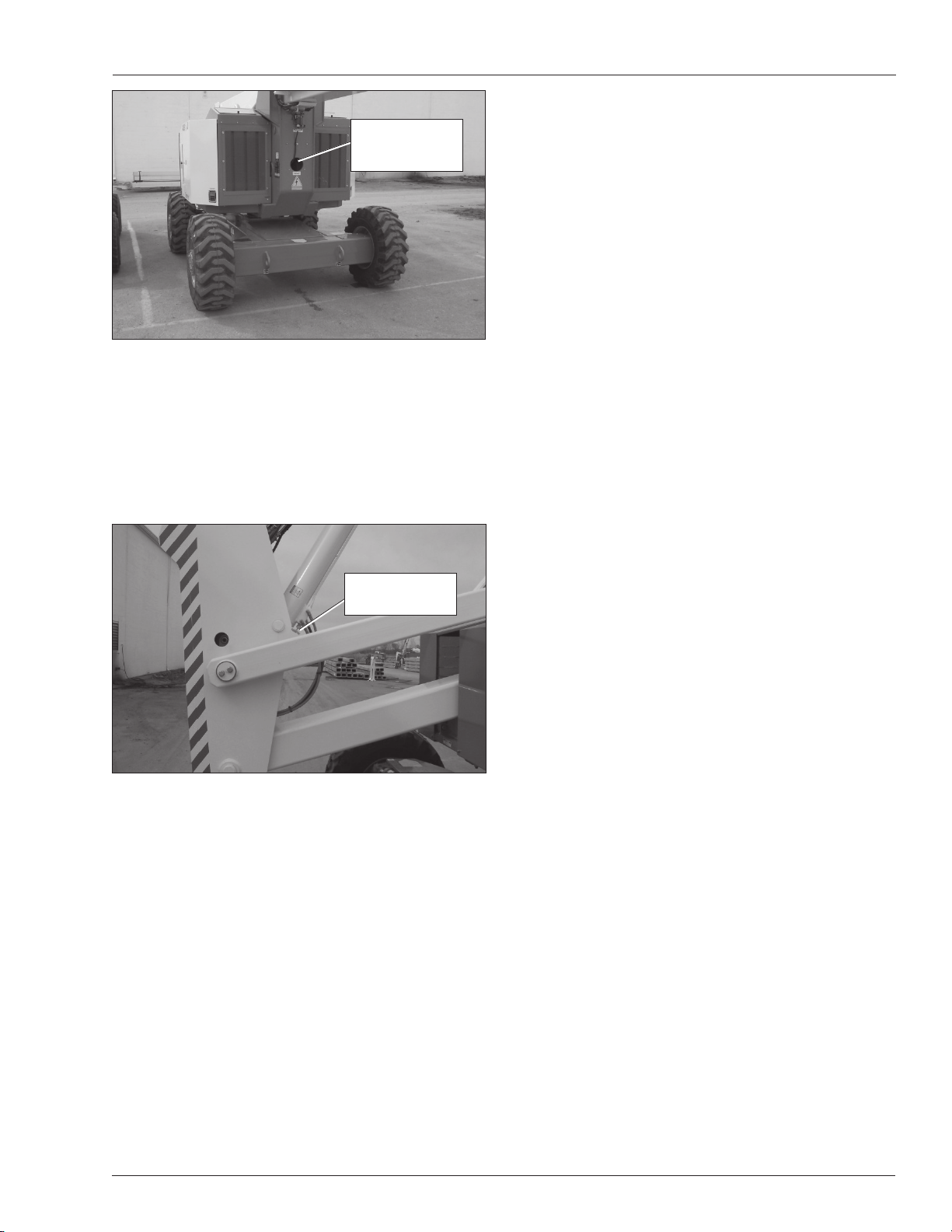
The riser and main booms can be lowered in an emergency using their respective emergency lowering knobs.
The emergency lowering knobs are at the base of the
lift cylinders. The emergency lowering knobs allow the
booms to be lowered only. Only use this method if the
engine will not start and the emergency power system
will not work.
ACaution
Fluid in the air line can damage some air tools or
freeze and damage the line. Drain and blow out the
air line after using it to conduct fluids.
Use the following procedure to drain the air line.
1. Close the input connector on the chassis.
2. Open the output connector at the platform.
3. Raise the boom slightly above horizontal.
4. Open the input connector on the chassis.
5. Allow the fluid to drain from the line.
6. Lower the boom and close both connections.
Driving Lights
The optional driving lights are for use in dimly lit areas
and are not intended for driving on public roadways.
There are two headlights at the front of the chassis and
two blinking taillights at the rear of the chassis. The lights
are operational when the battery disconnect switch and
the master switch are turned on.
ADanger
Pinch points exist between boom components and
between the booms and turntable. Death or serious
injury will result if the booms or platform lowers onto
personnel. Make sure all personnel stand clear while
lowering the booms.
Riser Boom
Use the following procedure to manually lower the riser
boom.
1. Slowly turn the knob (refer to Figure 5) to open the
bleed down valve. Control the rate of descent by
turning the knob.
AWarning
The potential for an accident increases when safety
devices do not function properly. Death or serious
injury can result from such accidents. Fully close
the emergency lowering knob before operating the
aerial platform.
2. Turn the knob to close the cylinder bleed down
valve.
Note
Working with the driving or platform work lights on, while
the engine is off, can discharge the batteries enough that
12 AB60JRT
Page 15
Operation
Emergency
Lowering Knob
Inside Turntable
Figure 5 – Riser Boom Emergency Lowering Knob
Main Boom
Use the following procedure to manually lower the main
boom.
1. Slowly turn the knob to open the bleed down valve on
the main boom lift cylinder (refer to Figure 6). Control
the rate of descent by turning the knob.
AWarning
The potential for an accident increases when safety
devices do not function properly. Death or serious
injury can result from such accidents. Fully close
the emergency lowering knob before operating the
aerial platform.
2. Turn the knob to close the cylinder bleed down
valve.
After Use Each Day
1. Ensure that the platform is fully lowered.
2. Park the machine on a firm level surface, preferably
under cover, secure against vandals, children and
unauthorized operation.
3. Turn the Chassis Key Switch to OFF and remove the
key to prevent unauthorized operation.
Emergency
Lowering Knob
Figure 6 – Main Boom Emergency Lowering Knob
AB60JRT 13
Page 16
Transporting the Machine
Transporting the Machine
Preparing for Transportation
Use the following procedure to prepare the aerial platform
for transportation.
1. Remove any unnecessary tools, materials, or other
loose objects from the platform.
2. Close and latch all cowling doors.
By Crane
Secure the straps to chassis lifting/lugs only .
Know the approximate location of the center of gravity
before lifting the machine off the ground. Refer to Figure
7.
ADanger
Lifting by Crane is for transport purposes only.
See Specifications for weight of machine and be
certain that the crane is of adequate capacity to lift
the machine.
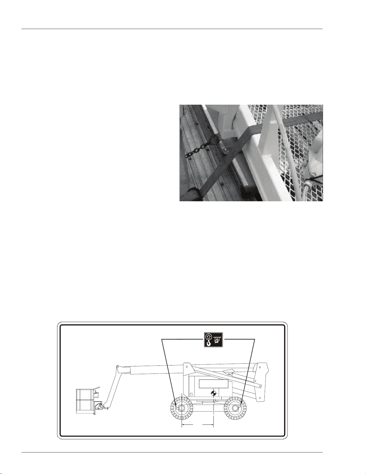
By Truck
1. Maneuver the machine into transport position and
chock wheels.
2. Place a wood block under the tip end of the jib foot.
Lower the platform so the foot rests on the wood
block.
ACaution
Ratchets, winches, and come-alongs can produce
enough force to damage machine components. Do
not over tighten the straps or chains when securing
the aerial platform to the transport vehicle.
3. Use a nylon strap to securely fasten the platform
against the wood block. Thread the strap over the
toeboard. Refer to Figure 8.
Figure 8 – Platform
4. Secure the machine to the transport vehicle with
chains or straps of adequate load capacity attached
to the chassis lifting/tie down points.
Tie-Down/Lifting Lug
Center of Gravity
in Stowed Position
1.4m
(55 )
"
approximate
0083427
0181889
Figure 7 – Center of Gravity
14 AB60JRT
Page 17
Maintenance
Maintenance
AWarning
Never perform service while the platform is elevated.
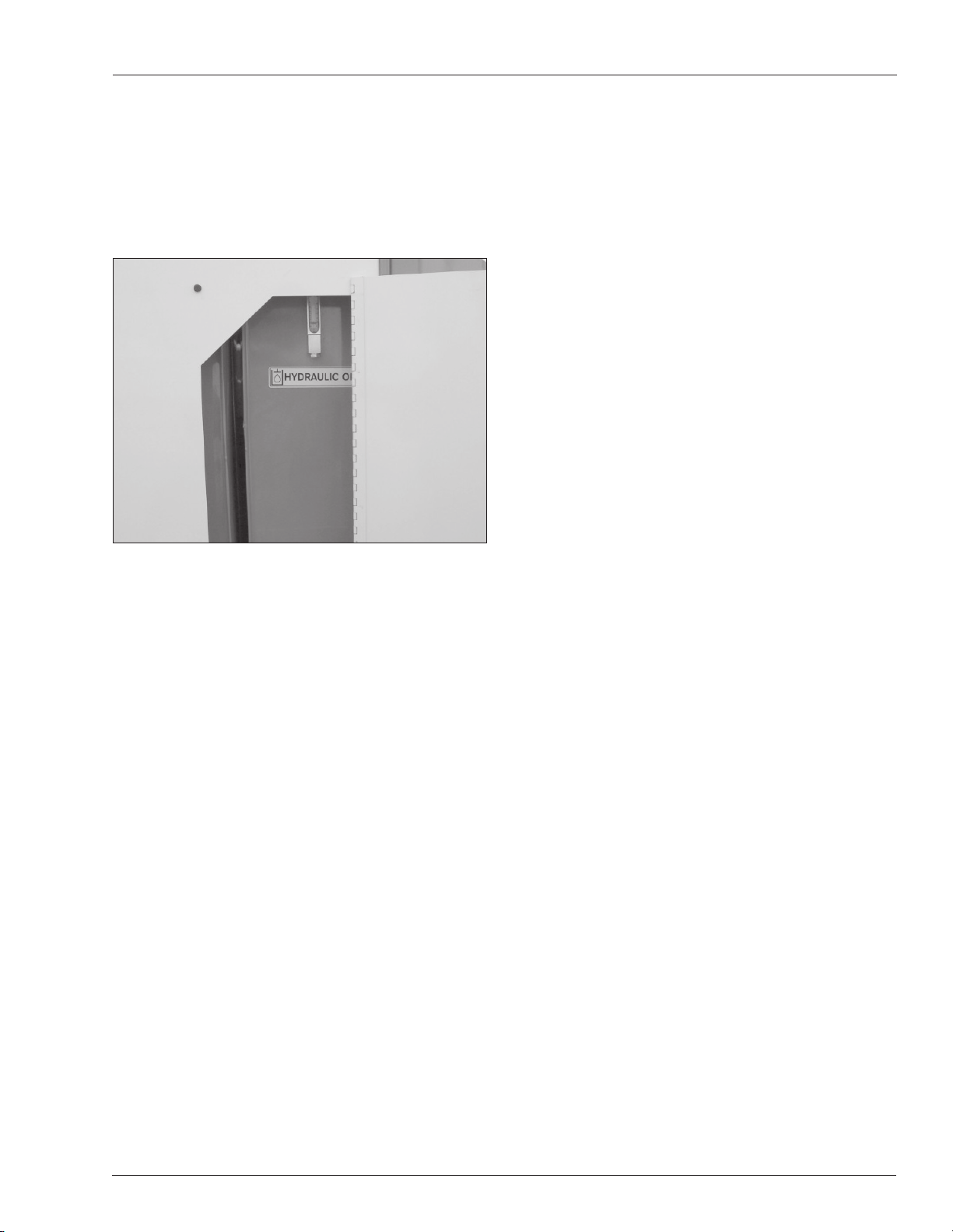
Hydraulic Fluid
The hydraulic fluid reservoir is located in the chassis door.
Refer to Figure 9.
Figure 9 – Hydraulic Fluid Reservoir
Battery Maintenance
AWarning
Hazard of explosive gas mixture. Keep sparks, flame,
and smoking material away from batteries.
Always wear safety glasses when working near batteries.
Battery fluid is highly corrosive. Thoroughly rinse
away any spilled fluid with clean water.
Always replace batteries with Snorkel batteries or
manufacturer approved replacements weighing 26,3
kg (58 lbs) each.
Check the battery fl uid level daily, especially if the
•
machine is being used in a warm, dry climate.
If electrolyte level is lower than 10 mm (3/8″) above the
plates add distilled water only . DO NOT use tap water with
high mineral content, as it will shorten battery life.
Keep the terminals and tops of the batteries clean.
•
Refer to the Service Manual to extend battery life and
•
for complete service instructions.
Note
Never add fluid if the platform is elevated.
Check Hydraulic Fluid
1. Make sure that the platform is fully lowered.
2. Open the left front cowling door.
3. Check the fluid level on the gauge on the end of the
reservior.
4. Add the appropriate fluid to bring the level to the FULL
mark. See “Specifications” on page 20.
Engine
Open the engine compartment doors on both sides of the
machine and visually inspect the engine and its components with the engine off.
Oil Level
Check the engine oil level before starting the engine
so the oil has drained to the pan. The proper oil level is
between the add and full marks on the dipstick.
The distance between the top and bottom dipstick marks
corresponds to about 1 l (1 quart US). Add oil, if necessary , before starting the engine.
AB60JRT 15
Page 18

Inspection and Maintenance Schedule
Inspection and Maintenance Schedule
The Complete Inspection consists of periodic visual and
operational checks, along with periodic minor adjustments
that assure proper performance. Daily inspection will prevent abnormal wear and prolong the life of all systems.
The inspection and maintenance schedule should be
performed at the specified intervals and after prolonged
periods of storage before returning the machine to service. Inspection and maintenance shall be performed by
personnel who are trained and familiar with mechanical
and electrical procedures.
AWarning
Before performing preventative maintenance, familiarize yourself with the operation of the machine.
Always block the elevating assembly whenever it is
necessary to perform maintenance while the platform
is elevated.
The daily preventative maintenance checklist has been
designed for machine service and maintenance. Please
photocopy the Daily Preventative Maintenance Checklist
and use the checklist when inspecting the machine.
16 AB60JRT
Page 19

Daily Preventative Maintenance Checklist
Preventative Maintenance Report
Daily Preventative Maintenance Checklist
Date:
Owner:
Serial No:
Serviced By:
Model No:
ITEM INSPECTION OR SERVICES Y N R
Operator’s Manual In place, all pages readable and intact
Engine
Oil level Between full and add marks
Coolant Liquid cooled engines – proper fluid level
Radiator Cap tight, good condition and clean
Air cooled engines Air intake and fan free of obstructions, belt in good condition
Fuel tank and line Tank full, cap in place and tight/ no leaks
Air filter Clear indicator
Charging system Proper operation
Cold weather start kit No damage or deformation
Electrical System
Emergency power battery Condition and charged for proper operation
Battery fluid level and terminals Proper level/clean, connectors tight
Cables and wiring harness No wear or physical damage
Hydraulic System
Fluid level Between full and add marks
Fluid filter Verify operation in the green zone
Hose, tubes and fittings No leaks
Cold weather warm-up kit Proper operation
Foam Filled Tyres and Wheels Good condition
Lower Control Station
Operating controls Proper operation
Emergency stop and emergency power Shuts off lower controls/proper operation
Emergency Lowering Proper operation
Level Sensor Sounds tilt alarm
Flashing Lights Proper operation
Sandblast Protection Kit In place and proper operation
Airline to Platform In place and proper operation
Structures
Weldments Welds intact, no damage or deformation
Slide pads In place, no damage or deformation
Fasteners In place and tight.
Upper Control Station
Guardrail system and lanyard anchors Welds intact, no damage or deformation
Operating controls Proper operation
Emergency stop and emergency power Shuts off upper controls/proper operation
Horn Sounds when activated.
Electrical power outlet Proper operation of outlet
Drive motion alarm Sounds when aerial platform moves
Driving and work lights Proper operation
Platform control cover In place and proper operation
Tow Kit In place, no damage or deformation
Placards and Decals In place and readable
Maintenance Table Key: Y = Yes/Acceptable, N = No/Not Accetable, R = Repaired/Acceptable
AB60JRT 17
Page 20
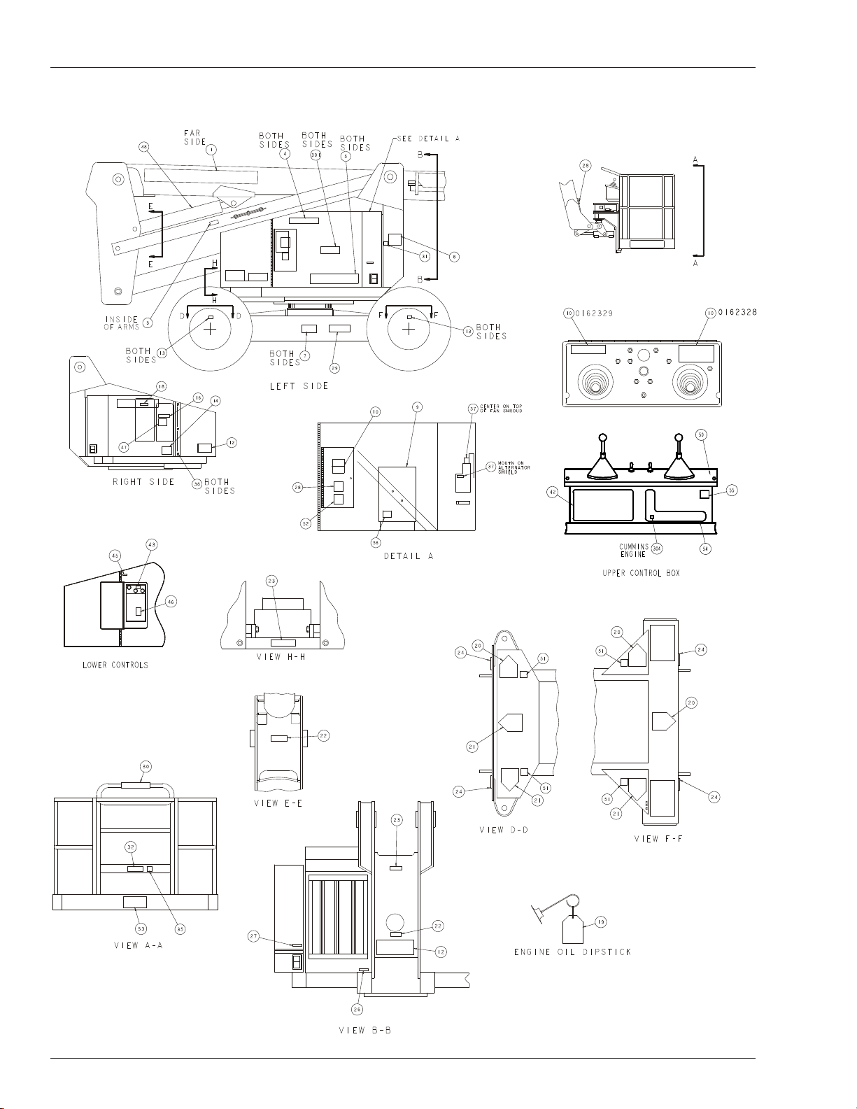
Decal Location
Decal Location
A18043K
18 AB60JRT – 0182264
Page 21

Decal Location
ITEM PART NO. QTY DESCRIPTION
1 508223-001 1 DECAL, UPRIGHT BRAND
LOGO
3 0181041E 2 DECAL, CAUTION SECURE
CROSSBARS – ENGLISH
0181041F 2 DECAL, CAUTION SECURE
CROSSBARS – FRENCH
0181041P 2 DECAL, CAUTION SECURE
CROSSBARS – SPANISH
0181041W 2 DECAL, CAUTION SECURE
CROSSBARS – SWEDISH
0181041D 2 DECAL, CAUTION SECURE
CROSSBARS – DUTCH
0181041G 2 DECAL, CAUTION SECURE
CROSSBARS – GERMAN
4 508222-001 2 DECAL, AB60JRT
5 508234-000 2 DECAL, UPRIGHT LOGO
7 0073298 2 DECAL, DANGER FOAM
FILLED TIRES
0073298F 2 DECAL, DANGER FOAM
FILLED TIRES – FRENCH
0073298P 2 DECAL, DANGER FOAM
FILLED TIRES – SPANISH
0073298W 2 DECAL, DANGER FOAM
FILLED TIRES – SWEDISH
0073298D 2 DECAL, DANGER FOAM
FILLED TIRES – DUTCH
0073298G 2 DECAL, DANGER FOAM
FILLED TIRES – GERMAN
8 0070901 1 PLACARD, CAUTION SERIAL
NUMBER
9 0073623 1 RECORD BOx
SUB-ASSEMBLY
10 0162328E 1 DECAL, BRIEF OPERATING
INSTRUCTIONS – ENGLISH
0162329E 1 DECAL, ADDITIONAL
OPERATING INSTRUCTIONS
– ENGLISH
0162328F 1 DECAL, BRIEF OPERATING
INSTRUCTIONS – FRENCH
0162329F 1 DECAL, ADDITIONAL
OPERATING INSTRUCTIONS
– FRENCH
0162328P 1 DECAL, BRIEF OPERATING
INSTRUCTIONS – SPANISH
0162329P 1 DECAL, ADDITIONAL
OPERATING INSTRUCTIONS
– SPANISH
0162328W 1 DECAL, BRIEF OPERATING
INSTRUCTIONS – SWEDISH
0162329W 1 DECAL, ADDITIONAL
OPERATING INSTRUCTIONS
– SWEDISH
ITEM PART NO. QTY DESCRIPTION
0162328D 1 DECAL, BRIEF OPERATING
INSTRUCTIONS – DUTCH
0162329D 1 DECAL, ADDITIONAL OP-
ERATING INSTRUCTIONS
– DUTCH
0162328G 1 DECAL, BRIEF OPERATING
INSTRUCTIONS– GERMAN
0162329G 1 DECAL, ADDITIONAL
OPERATING INSTRUCTIONS
– GERMAN
12 0162336E 3 DECAL, DANGER ELECTRI-
CAL HAzARD – ENGLISH
0162366 3 DECAL, DANGER ELECTRI-
CAL HAzARD
0162336F 3 DECAL, DANGER ELECTRI-
CAL HAzARD – FRENCH
0162366 3 DECAL, DANGER ELECTRI-
CAL HAzARD
0162336P 3 DECAL, DANGER ELECTRI-
CAL HAzARD – SPANISH
0162366 3 DECAL, DANGER ELECTRI-
CAL HAzARD
0162336W 3 DECAL, DANGER ELECTRI-
CAL HAzARD – SWEDISH
0162366 3 DECAL, DANGER ELECTRI-
CAL HAzARD
0162336D 3 DECAL, DANGER ELECTRI-
CAL HAzARD – DUTCH
0162366 3 DECAL, DANGER ELECTRI-
CAL HAzARD
0162336G 3 DECAL, DANGER ELECTRI-
CAL HAzARD – GERMAN
0162366 3 DECAL, DANGER ELECTRI-
CAL HAzARD
13 0072276 4 DECAL, LUG NOT TORQUE
450-500 FT LB
14 0073585 2 DECAL, MADE IN THE USA
16 0071927 1 DECAL, HYDRAULIC OIL
18 0071926 1 DECAL, DIESEL FUEL
19 0073139 1 CRANKCASE OIL TAG
20 0070540 3 DECAL, YELLOW ARROW
21 0070541 3 DECAL, BLUE ARROW
22 0100164 2 DECAL, EMERGENCY
BLEED DOWN VALVE
23 0150602 2 DECAL, DANGER
DESCENDING BOOM
0150602F 2 DECAL, DANGER
DESCENDING BOOM
– FRENCH
0150602P 2 DECAL, DANGER
DESCENDING BOOM
– SPANISH
AB60JRT – 0182264 19
Page 22

Decal Location
ITEM PART NO. QTY DESCRIPTION
0150602W 2 DECAL, DANGER
DESCENDING BOOM
– SWEDISH
0150602D 2 DECAL, DANGER DE-
SCENDING BOOM – DUTCH
0150602G 2 DECAL, DANGER DE-
SCENDING BOOM
– GERMAN
24 0083427 4 DECAL, LIFT/TIE DOWN
SYMBOL
26 0073492 1 DECAL, ROTATE WHILE
GREASING
0073492F 1 DECAL, ROTATE WHILE
GREASING – FRENCH
0073492P 1 DECAL, ROTATE WHILE
GREASING – SPANISH
0073492W 1 DECAL, ROTATE WHILE
GREASING – SWEDISH
0073492D 1 DECAL, ROTATE WHILE
GREASING – DUTCH
0073492G 1 DECAL, ROTATE WHILE
GREASING – GERMAN
27 0073491 1 DECAL, SAFE OPERATION
INFO
28 0162336E 3 DECAL, DANGER ELECTRI-
CAL HAzARD – ENGLISH
0162366 3 DECAL, DANGER
ELECTRICAL HAzARD
0162336F 3 DECAL, DANGER ELECTRI-
CAL HAzARD – FRENCH
0162366 3 DECAL, DANGER
ELECTRICAL HAzARD
0162336P 3 DECAL, DANGER ELECTRI-
CAL HAzARD – SPANISH
0162366 3 DECAL, DANGER
ELECTRICAL HAzARD
0162336W 3 DECAL, DANGER ELECTRI-
CAL HAzARD – SWEDISH
0162366 3 DECAL, DANGER
ELECTRICAL HAzARD
0162336D 3 DECAL, DANGER ELECTRI-
CAL HAzARD – DUTCH
0162366 3 DECAL, DANGER
ELECTRICAL HAzARD
0162336G 3 DECAL, DANGER ELECTRI-
CAL HAzARD – GERMAN
0162366 3 DECAL, DANGER
ELECTRICAL HAzARD
29 0181899 1 DECAL, LIFT/TIE DOWN
LOCATION
30 0072531 1 DECAL, DANGER
ELECTRICAL HAzARD
31 0162311 1 DECAL, CE
ITEM PART NO. QTY DESCRIPTION
32 0071425 1 PLACARD, PLATFORM
IDENTIFICATION
33 1 PLACARD, PLATFORM
CAPACITY
(CONSULT FACTORY)
35 0150448 1 DECAL, ATTACH FALL
RESTRAINTS
37 0151410E 2 DECAL, DANGER ROTATING
PARTS – ENGLISH
0151410F 2 DECAL, DANGER ROTATING
PARTS – FRENCH
0151410P 2 DECAL, DANGER ROTATING
PARTS – SPANISH
0151410W 2 DECAL, DANGER ROTATING
PARTS – SWEDISH
0151410D 2 DECAL, DANGER ROTATING
PARTS – DUTCH
0151410G 2 DECAL, DANGER ROTATING
PARTS – GERMAN
38 5560080 6 BUMPER
42 0072530 1 DECAL, DANGER ELECTRI-
CAL HAzARD
43 0191892 1 PLACARD, ENGINE PROTEC-
TION SYSTEM
45 0073089 1 DECAL, BATTERY DISCON-
NECT
46 0075563 1
47 703003 1 DECAL, LUBE RECOMMEN-
48 0074311 8 DECAL, DANGER CYLINDER
49 0084213 1 DECAL, COLD START
50 0180916 1 PLACARD, LOWER
51 0182072E 4 DECAL, WHEEL LOADING
52 0182077E 1 DECAL, CE NOISE LEVEL
54 0180846 1 PLACARD, UPPER CONTROL
55 0161819E 1
56 0074372 1 PLACARD, ENGINE RPM
301 508235-000 2 DECAL, 4x4 LOGO
DECAL, DO NOT USE ETHER
DATIONS
FAILURE
– ONE PER CYLINDER
CONTROLS
– ENGLISH
– ENGLISH
– FRONT
DECAL, EMERGENCY LOW-
ERING
20 AB60JRT – 0182264
Page 23
Speci? cations
Speci? cations
Aerial Platform
66( m 11.02 thgieh gnikroW ′)
Maximum platform height 18.29 m (60′)
Horizontal reach 13.1 m (43′ 1″)
Main boom elevation -1° to +75°
Turntable rotation 360° continuous
Turning radius, inside
8( m 54.2 evird leehw owT ′)
Four wheel drive 5.24 m (17′ 2
1
/2″)
8( m 4.2 esableehW ′)
1( mc 03 ecnaraelc dnuorG ′)
Tailswing
5( m 45.1 dewotS ′)
0( m 0 gnikroW ′)
Maximum wheel load 5,670 kg (12,500 lbs)
Maximum ground pressure 5.76 kg/cm² (82 psi)
Weight, EVW approximate 11,249 kg (24,800 lbs)
7( m 4.2 htdiw dewotS ′ 111/2″)
92( m 9.8 htgnel dewotS ′ 2″)
8( m 5.2 thgieh dewotS ′ 3″)
Platform
Dimensions
Standard steel 76 cm x 152 cm (30″ x 60″)
Rated work load 227 kg (500 lb)
Optional aluminum 76 cm x 152 cm (30″ x 60″)
Rated work load 227 kg (500 lb)
Optional aluminum 76 cm x 243 cm (30″ x 96″)
Rated work load 227 kg (500 lb)
WCC °09 ot WC °09 noitatoR
Maximum number of occupants 2 people
Optional AC generator 220 VAC
Tires
Electrical System
Voltage 12 V DC negative chassis ground
Source One - 12 V 550 CCA battery
Fluid recommended distilled water
Hydraulic System
Maximum pressure 20,700 kPa (3,000 psi)
Reservoir capacity 94.6 l (25 US gal)
System capacity 132.5 l (35 US gal)
Maximum operating temperature 93°C (200°F)
Hydraulic fluid recommended
Above -12°C (10°F) Mobil DTE-13M (ISO VG32)
Below -12°C (10°F) Mobil DTE-11M (ISO VG15)
Engine
Fuel Tank Capacity
Ambient Air Temperature Operating Range
C°34 ot C°81- suisleC
Maximum Wind Speed
Gust or steady 45 km/h (28 mph)
Vibration less than 2.5 m/sec
Sound Threshold below 97 dB(A)
ylp 21 ,5.91-51 dellif maoF
3.3B snimmuC leseiD
)lag SU 04( l 4.151 leseiD
F°011 ot F°0 tiehnerhaF
2
Function Speed
Turntable rotation, 360 degrees 123 to 125 seconds
Main boom
Riser boom
Jib boom
Platform rotation, 180 degrees 16 to 20 seconds
Drive
4x4 and 4x2
High, booms stowed 5.1 km/h (3.2 mph)
Mid, booms stowed 2.9 km/h (1.8 mph)
4x4
Low, booms down/retracted 1.6 km/h (1 mph)
Low, booms up/retracted 1 km/h (0.6 mph)
4x2
Low, booms down/retracted 1.1 km/h (0.7 mph)
Low, booms up/retracted 1.1 km/h (0.7 mph)
Drive System
%02 ytilibaedarG
Working Envelope
sdnoces 25 ot 74 pU
sdnoces 25 ot 74 nwoD
sdnoces 83 ot 03 dnetxE
18.3
(60)
sdnoces 83 ot 03 tcarteR
sdnoces 03 ot 42 pU
15.2
(50)
sdnoces 02 ot 61 nwoD
sdnoces 21 ot 9 pU
sdnoces 11 ot 7 nwoD
12.2
(40)
9.1
(30)
6.1
(20)
3.0
(10)
0
evird leehw ruoF dradnatS
evird leehw owT lanoitpO
3.0
(10)
0
3.0
(10)
6.1
(20)
9.1
(30)
12.2
(40)
Meters
(Feet)
21AB60JRT
Page 24

Page 25
AB60JRT
Betriebsanleitung
Bestellnummer 508321-001(DE)
June 08
Page 26

Page 27

Inhaltsverzeichnis
Konformitätserklärung ................................................2
Sicherheitsregeln ........................................................ 3
Einleitung .................................................................... 4
Komponentenbezeichnung ......................................... 4
Spezielle Einschränkungen ........................................5
Plattformbelastung ..................................................5
Manuelle Krafteinwirkung ........................................5
Plattformüberlastungs-Erkennungssystem .............5
Beaufort-Skala ........................................................5
Bedien- und Anzeigeelemente....................................6
Batterie-Trennschalter .............................................6
Untere Bedienelemente und -anzeigen ...................6
Obere Bedienelemente und -anzeigen ...................6
Sicherheitsprüfung vor dem Betrieb ...........................7
Systemfunktionsprüfung ............................................. 8
Bedienung ..................................................................9
Starten bei kaltem Wetter ........................................9
Hydrauliksystem – Erwärmen bei kaltem Wetter ....9
Hydrauliksystem - Erwärmungsschalter ..................9
Manuelles Erwärmen des Hydrauliksystems ..........9
Vorbereitung für den Betrieb .................................10
Untere Bedienelemente ........................................10
Obere Bedienelemente .........................................10
Auslegerbetrieb .....................................................10
Fahren und Lenken ...............................................10
Fahrtgeschwindigkeiten ........................................ 11
Fahrtwarnalarm ..................................................... 11
Wechselstromgenerator ........................................ 11
Druckluftleitung .....................................................12
Fahrtscheinwerfer .................................................12
Plattform-Arbeitsbeleuchtung ................................ 12
Notfallabsenkung ..................................................12
Inhaltsverzeichnis
Hebebaum ............................................................. 12
Hauptausleger ....................................................... 13
Täglicher Arbeitsabschluss ...................................13
Transport der Maschine ............................................14
Transportvorbereitung ...........................................14
Durch Kran ............................................................14
Mit Lkw ..................................................................14
Wartung ....................................................................15
Hydrauliköl ............................................................15
Hydrauliköl prüfen .................................................15
Motor .....................................................................15
Ölstand .................................................................. 15
Batteriewartung .....................................................15
Inspektions- und Wartungsplan ................................16
Checkliste zur täglichen vorbeugenden Wartung .....17
Bericht über die vorbeugende Wartung .................17
Position der Hinweisschilder.....................................18
Technische Daten .....................................................20
Hubplattform .......................................................... 20
Plattform ................................................................ 20
Funktionsgeschwindigkeit .....................................20
Antriebssystem ...................................................... 20
Reifen .................................................................... 20
Elektrisches System ..............................................20
Hydrauliksystem .................................................... 20
Motor .....................................................................20
Kraftstofftankinhalt .................................................20
Umgebungstemperaturbereich im Betrieb ............20
Maximale Windgeschwindigkeit ............................20
Vibration ................................................................20
Lärmabgabe ..........................................................20
Arbeitsbereich .......................................................20
AB60JRT 1
Page 28
EU-MASCHINEN-KONFORMITÄTSERKLÄRUNG
MASCHINE:
Hubplattform mit Fahrantrieb, bekannt unter:
Typ: SNORKEL AB60J (Upright AB60JRT)
Seriennummer:
Die oben spezifi zierte Maschine entspricht folgenden Bestimmungen:
Maschinenrichtlinie 98/37/EC (unter Verwendung des Dokuments EU-Gesetzgebung über Maschinen und der
Anleitungen von EN280:2001 + Änderung A1 :2004).
EU-Richtlinie 89/336/EEC über Elektromagnetische Verträglichkeit entspr. der Änderungen 93/68/EEC und 92/31/
EC
EU-Richtlinie 73/23/EEC über Niederspannungsgerätesicherheit entsprechend der Änderung in 93/68/EE
EU-Richtlinie 2000/14/EC über Geräuschemissionen von im Freien betriebenen Geräte und Maschinen.
Durchgeführt in Übereinstimmung mit EN 3744:1995
Gemessener Schalldruckpegel
Garantierter Schalldruckpegel 100 dB
EU-Prüfzertifi kat Nr.:
91 dB Min
100 dB Max
Hinweis: Bei Änderungen an der spezifi zierten Einheit wird diese Erklärung ungültig.
2 AB60JRT
Page 29
SICHERHEITSREGELN
AWarnung
Alle Personen müssen alle Sicherheitsregeln und Bedienungsanleitungen sorgfältig lesen, verstehen und befolgen, bevor sie eine UpRight-Hubarbeitsbühne bedienen oder daran Wartungsarbeiten
durchführen.
Stromschlaggefahr Kippgefahr Kollisionsgefahr Sturzgefahr
DIESE MASCHINE IST
NICHT ISOLIERT
VERWENDUNG DER HUBARBEITSBÜHNE: Diese Hubarbeitsbühne ist dazu vorgesehen, sowohl Personen mit den Werkzeugen als auch das für die
Arbeit benötigte Material zu heben. Sie wurde für Reparatur- und Montagearbeiten und für Arbeiten an Überkopf-Arbeitsplätzen (Decken, Krane, Dachkonstruktionen, Gebäude etc.) bestimmt. Andere Verwendungen oder Änderungen der Hubarbeitsbühne müssen von UpRight genehmigt werden.
DIESE HUBARBEITSBÜHNE IST NICHT ISOLIERT! Aus diesem Grund ist unbedingt geboten, von stromführenden Teilen elektrischer Anlagen einen
sicheren Abstand beizubehalten!
Die Überschreitung der spezifi zierten Maximalbelastung ist verboten! Siehe die Details unter “Plattformkapazität” auf Seite 5.
Die Verwendung und der Betrieb der Hubarbeitsbühne als Hebewerkzeug oder Kran sind verboten!
NIEMALS die für diese Maschine zugelassene manuelle Krafteinwirkung überschreiten. Siehe die Details unter “Manuelle Krafteinwirkung” auf Seite 5.
Alle Plattformbelastungen gleichmäßig auf der Plattform VERTEILEN.
NIEMALS die Maschine bedienen, ohne zuvor den Arbeitsbereich auf Gefahren auf der Fahrfäche wie Löcher, nachgebende Stellen, Unebenheiten,
Randsteine oder Fremdkörper zu untersuchen; solche Stellen sind zu vermeiden.
Mit der Maschine nur auf Fahrfl ächen ARBEITEN, die die Radlast aufnehmen können.
NIEMALS die Maschine betreiben, wenn die Windgeschwindigkeit die Nennwerte der Maschine überschreitet. Siehe die „Beaufort-Skala“ auf Seite 5.
Unter windigen oder böigen Wetterbedingungen nicht mit der Hubarbeitsbühne arbeiten. An der Hubarbeitsbühne keine Teile wie Plakattafeln, Banner,
Flaggen etc. anbringen, die den Winddruck erhöhen würden.
IM NOTFALL den NOTHALT-KNOPF drücken, um alle motorgetriebenen Funktionen zu deaktivieren.
WENN DER ALARM ERTÖNT während die Plattform angehoben ist, STOPPEN und die Plattform vorsichtig ablassen und die Maschine auf eine feste
und ebene Fahrfl äche fahren.
Hochklettern am Plattformgeländer, darauf stehen oder von der Plattform auf Gebäude, Stahl- oder vorgefertigte Betonstrukturen etc. umsteigen ist
verboten!
Demontage der Eingangstür oder anderer Geländerkomponenten ist verboten! Stets sicherstellen, dass die Eingangstür geschlossen ist! Es ist verbo-
ten, die Eingangstür bei angehobener Plattform offen zu lassen!
Die Höhe oder die Reichweite durch die Platzierung von Leitern, Gerüsten oder ähnlichen Einrichtungen auf der Plattform zu erweitern ist verboten!
NIEMALS bei angehobener Plattform an der Maschine Reparaturarbeiten durchführen, ohne die Hebeeinrichtung zu blockieren.
Vor dem Betrieb die Maschine sorgfältig auf Risse in Schweißnähten, lose oder fehlende Bauteile, Hydrauliklecks, lose Kabelverbindungen und beschä-
digte Kabel oder Schläuche INSPIZIEREN.
VERIFIZIEREN, dass alle Hinweisschilder an ihrer Stelle und lesbar sind, bevor die Maschine verwendet wird.
NIEMALS eine Maschine verwenden, die beschädigt ist, nicht richtig funktioniert oder beschädigte oder fehlende Hinweisschilder hat.
Die Umgehung einer Sicherheitseinrichtung ist verboten, denn dies repräsentiert eine Gefahr für die Personen auf der Hubarbeitsbühne und innerhalb
ihres Arbeitsbereiches.
NIEMALS die Batterien in der Nähe von Funken oder offenen Flammen laden. Während des Ladens geben Batterien explosives Wasserstoffgas ab.
Änderungen an der Hubarbeitsbühne sind verboten und nur nach Genehmigung von UpRight erlaubt.
Nach dem Einsatz ist die Arbeitsplattform vor unerlaubter Verwendung durch Abschalten des Schlüsselschalters und Entfernen des Schlüssels zu sichern. Die Fahrt der Hubarbeitsbühne auf öffentlichen Straßen obliegt den nationalen Verkehrsgesetzen.
Bestimmte innewohnende Risiken bleiben bei der Bedienung dieser Maschine trotz richtiger Konstruktionspraktiken und Absicherungen vorhanden.
An der Plattform sind Verankerungen für Fallrückhaltegurte vorgesehen und der Hersteller empfi ehlt die Verwendung dieses Gurtzeug, besonders dann,
wenn es von nationalen Sicherheitsbestimmungen vorgeschrieben ist.
Es muss darauf geachtet werden, dass die Maschine alle Anforderungen hinsichtlich der Stabilität während der Verwendung, des Transports,
des Zusammenbaus oder der Zerlegung bei der Außerbetriebsetzung, Tests oder vorhersehbaren Betriebsausfällen erfüllt.
Im Falle eines Unfalls oder eines Betriebsausfalls das Kapitel „Notfallabsenkung“ auf Seite 12 beachten. Die Hubarbeitsbühne nicht in Betrieb
setzen, wenn sie beschädigt ist oder nicht richtig funktioniert. Bevor die Hubarbeitsbühne wieder in Betrieb gesetzt werden kann, muss das
Problem von qualifi ziertem Wartungspersonal beseitigt werden.
NIEMALS die Plattform heben
oder die Maschine mit angehobener Plattform bewegen,
außer wenn die Maschine
auf einer festen und ebenen
Oberfl äche steht.
NIEMALS die Plattform ohne
Überprüfung nach Behinderungen oder anderen Gefahren überkopf positionieren.
NIEMALS auf dem Plattformgeländer stehen, sitzen oder
daran hochklettern
AB60JRT 3
Page 30
Einleitung
Einleitung
Dieses Handbuch betrifft die Hubarbeitsbühne AB60JRT
und muss stets bei der Maschine aufbewahrt werden.
Lesen, verstehen und befolgen Sie alle Sicherheitsregeln und Bedienungsanweisungen, bevor Sie versuchen, die Maschine in Betrieb zu setzen.
Komponentenbezeichnung
Obere Bedienelemente
Not-Ablass-
ventil
Wenn Sie sich wegen Wartungs- oder Teileinformationen
an UpRight wenden, stellen Sie sicher, dass Sie die
MODELLBEZEICHNUNG und die SERIENNUMMERN
angeben. Wenn das Typenschild fehlen sollte, fi nden
Sie die SERIENNUMMER auch neben der hinteren
Antriebsmotorabdeckung eingeschlagen.
Kraftstofftank
Hydrauliköl-
Tank
Not-Ablass-
ventil
Schwebende
Wiege
Hebebaum
Unteres
Bedienfeld
Controls
Batterie-Trennschalter
Battery
Rechte Seite
Typenschild-
Engine
Hydrauliköl-
Filter
Position
Hauptausleger
Bedienungs-
Handbuch
Fahrgestell
Oberer Ausleger
Schwenkarm
Lenkräder
Plattform
Lenkräder
Plattform-
Fußschalter
Linke Seite
4 AB60JRT
Page 31

Spezielle Einschränkungen
Spezielle Einschränkungen
Fahren mit angehobener Plattform ist auf den Kriechgeschwindigkeitsbereich beschränkt. Das Anheben
der Plattform ist auf feste und ebene Oberfl ächen be-
schränkt.
AGefahr
Die Hubfunktion darf NUR benutzt werden, wenn
die Arbeitsplattform auf einer ebenen und festen
Oberfl äche steht.
Die Arbeitsplattform ist NICHT zum Fahren über unebenen, rauen oder weichen Untergrund geeignet.
Plattformbelastung
Die Plattform kann mit zwei Personen und deren Werkzeuge belegt werden. Die maximale Plattformbelastung
der Hubarbeitsbühne fi nden Sie unter „Technische Daten“
auf Seite 20.
AGefahr
Überschreiten Sie NICHT die maximale Plattformbelastung oder –belegung dieser Maschine.
Manuelle Krafteinwirkung
Die manuelle Krafteinwirkung ist die von den Benutzern
ausgeübte Kraft auf Objekte wie Wände oder andere
Strukturen außerhalb der Arbeitsplattform.
Die maximal zulässige manuelle Krafteinwirkung ist auf
200 N (45 lbs) pro Benutzer, also auf 400 N (90 lbs) für
zwei Benutzer beschränkt.
AGefahr
Überschreiten Sie NICHT die maximale Höhe der
manuellen Krafteinwirkung auf diese Maschine.
Plattformüberlastungs-Erkennungssystem
Alle Funktionen von den oberen und unteren Bedienelementen werden gestoppt, wenn die Plattformüberlastungsschwelle überschritten wird. Es ertönt ein unterbrochener Hupenton und die Plattform-Überlastungswarnlampe blinkt, bis die Überlastung von der Plattform
entfernt wird. Danach können die Maschinenfunktionen
wieder bedient werden.
Wenn die Plattform erheblich überlastet wird oder wenn
an der Plattform eine Krafteinwirkung nach oben etwa
2225 N (500 lbs.) überschreitet, dann schaltet das System in einen Fehlermodus und stoppt alle Funktionen
der oberen und unteren Bedienelemente. Es ertönt ein
konstanter Hupenton und die Überlastungswarnlampe auf
dem oberen und unteren Bedienfeld bleibt erleuchtet.
Das System bleibt im Fehlermodus bis die Überlastung
von der Plattform entfernt wird und der Nothalt-Knopf
oder der Startschalter wird zur Rücksetzung des Systems
einmal aus- und wieder eingeschaltet. Danach können
die Maschinenfunktionen wieder bedient werden.
AVorsicht
Das Notstromversorgungssystem ist nur zum Senken
und Verstauen im Notfall vorgesehen. Die Betriebsdauer der Pumpe ist von der Batterieladung abhängig. Für den normalen Betrieb darf dieses System
nicht verwendet werden.
Wenn das Plattformüberlast-Erkennungssystem während
der Bedienung der Maschine auslöst oder wenn sich das
System im Fehlermodus befi ndet und nicht zurückgesetzt
werden kann, dann kann das Notstromversorgungssystem immer noch für Notfall-Maschinenfunktionen
verwendet werden.
AGefahr
Die Hubarbeitsbühne kann umkippen, wenn Sie
instabil wird. Solch ein Kippunfall kann schwere bis
tödliche Verletzungen verursachen. Überschreiten
Sie deshalb nicht die auf dem betreffenden Hinweisschild angegebenen Belastungswerte.
Das Überlastungs-Erkennungssystem ist inaktiv, wenn
die Maschine mit verstauten Auslegern gefahren wird.
Dadurch kann die Maschine auch über raue Bodenzustände gefahren werden ohne dass eine Überlastung
erkannt wird.
Um wiederholte Auslösungen des Systems während
des Maschinenbetriebs zu vermeiden, ist bei folgenden
Maschinenfunktionen eine Verzögerung von 5 Sekunden
vorhanden:
Anlassen des Motors.
•
Platzierung des Fahrantriebs-/Auslegerschalters in
•
die Auslegerposition, während der Hauptausleger
tiefer als horizontal gesenkt und vollständig zurückgezogen ist.
Entfernen einer Überlastung von der Plattform.
•
Beaufort Skala
Die Maschine niemals betreiben, wenn die Windgeschwindigkeit 12,5 m/s (28 mph) [Beaufort-Skala 6]
überschreitet. Siehe Abbildung 1.
BEAUFORT-
BEWERTUNG
3 3,4~5,4 12,25~19,4 11.5~17.75 7.5~12.0 Papier und dünne Äste bewegen sich, Fahnen wehen..
4 5,4~8,0 19,4~28,8 17.75~26.25 12.0~18 Staub und/oder Papier wird hochgeblasen und kleine Äste schwingen.
5 8,0~10,8 28,8~38,9 26.25~35.5 18~24.25
6 10,8~13,9 38,9~50,0 35.5~45.5 24.5~31
7 13,9~17,2 50,0~61,9 45.5~56.5 31.~38.5 Ganze Bäume schwingen. Gehen gegen den Wind ist schwierig.
AB60JRT 5
m/s km/h ft/s mph
WINDGESCHWINDIGKEIT
Abbildung 1 – Beaufort-Skala
BEDINGUNGEN AM BODEN
Büsche mit Blättern beginnen zu schwingen. Wellen werden auf
Teichen sichtbar.
Baumäste bewegen sich. Elektrische Leitungen singen. Das
Öffnen eines Regenschirms ist schwierig.
Page 32

Bedien- und Anzeigeelemente
Bedien- und Anzeigeelemente
Der Bediener muss die Position aller Bedien- und Anzeigenelemente sowie deren Funktion und Bedienung
vollständig kennen, bevor die Bedienung der Maschine
versucht wird.
1
Abbildung 2 – Batterie-Trennschalter
1. Batterie-Trennschalter
7
8
10
3
13. Plattformschwenkschalter
14. Motor-/Notstromschalter
15. Drosselklappenschalter
16. Hydraulik-Erwärmungsschalter (optional)
17. Trennschalter-Rücksetztasten
18. Plattform-Überlastwarnleuchte
19. Betriebsstundenzähler
34
23
24
25
26
33
20
35
27
31
32
29
30
28
22
36
9
6
15
Abbildung 3 – Untere Bedien- und Anzeigeelemente
2. Nothalttaste
3. Steuerungswahlschalter
4. Startschalter
5. Bodenbedienschalter
6. Schwenkschalter
7. Hebebaum-Hebeschalter
8. Hauptausleger-Hebeschalter
9. Auslegerverlängerungsschalter
10. Schwenkarmschalter
11. Auslegergeschwindigkeitsschalter
12. Plattformausrichtschalter
12
16
17
18
13
11
2
4
14
5
19
21
Abbildung 4 – Obere Bedien- und Anzeigeelemente
20. Nothalttaste
21. Startschalter
22. Fahrantrieb-/Auslegerwahlschalter
23. Ausleger-Joystick
24. Hebebaum-Hubfunktionsschalter
25. Auslegerverlängerungsschalter
26. Schwenkarmschalter
27. Auslegergeschwindigkeitsschalter
28. Fahrantriebs-Joystick
29. Fahrantriebsbereichsschalter
30. Plattformausrichtschalter
31. Plattformschwenkschalter
32. Motor-/Notstromschalter
33. Drosselklappenschalter
34. Plattform-Überlastwarnleuchte
35. Maschinen-/Generatorschalter
6 AB60JRT
Page 33

Sicherheitsprüfung vor dem Betrieb
Sicherheitsprüfung vor dem Betrieb
Hinweis:
Sorgfältig Sicherheitsregeln, Bedienungsanweisungen,
Aufkleber und nationale Sicherheitsanweisungen/-anforderungen lesen, verstehen und befolgen. Folgende
Schritte sind jeden Tag vor der Verwendung durchzuführen.
1. Abdeckungen des Drehtisches öffnen und diesen
auf Schäden, Hydrauliköllecks oder fehlende Teile
inspizieren.
2. Den Hydraulikölstand bei vollständig abgesenkter Plattform prüfen. Der Hydraulikölstand muss
zwischen den auf dem Sichtglas vorhandenen
Markierungen für Voll und Nachfüllen stehen. Falls
erforderlich, das empfohlene Hydrauliköl nachfüllen.
Siehe “Technische Daten” auf Seite 20.
3. Prüfen, ob der Flüssigkeitsstand in den Batterien
korrekt ist. Siehe “Batteriewartung” auf Seite 15.
4. Prüfen, ob alle Geländer an ihrem Platz sind und
ob alle Befestigungen fest angezogen sind.
5. Die Maschine gründlich auf Rissen in Schweißnähten und strukturelle Schäden, lose oder fehlende
Bauteile, Hydrauliköllecks, beschädigte Steuerungskabel und lose Kabelanschlüsse prüfen.
AB60JRT 7
Page 34

Systemfunktionsprüfung
Systemfunktionsprüfung
Die Position der verschiedenen Bedienungs- Und
Anzeigeelemente fi nden Sie unter „Bedienungs- und
Anzeigelemente“ auf Seite 6.
AWarnung
Während der Durchführung folgender Prüfungen in
SICHERER ENTFERNUNG von der Arbeitsplattform
stehen.
Bevor Sie die Maschine in Betrieb setzen überprüfen
Sie den Arbeitsbereich auf Gefahren auf der Fahrfl ä-
che wie Löcher, nachgebende Stellen, Randsteine
und Fremdkörper.
Prüfen Sie ALLE Richtungen einschließlich über
der Plattform nach Hindernissen und elektrischen
Leitungen.
1. Bewegen Sie die Maschine falls erforderlich zu einer
unbehinderten Stelle, um die vollständige Anhebung
zu ermöglichen.
2. Ziehen Sie den unteren Nothalt-Schalter in die
Position EIN.
3. Ziehen Sie den oberen Nothalt-Schalter in die Position EIN.
4. Inspizieren Sie die Hebeeinrichtung, den Hebezylinder, die Kabel und die Schläuche entsprechend auf
gerissene Schweißnähte, strukturelle Schäden, lose
Einzelteile, Hydrauliköllecks, lose Kabelanschlüsse
und fehlerhafte Funktion. Prüfen Sie auf fehlende
oder lose Teile.
5. TTesten Sie jede Maschinenfunktion (Heben,
Schwenken, Teleskop Ein-/Ausfahren) an der
unteren Bedienstation, indem Sie den Bodenbedienschalter nach oben halten während Sie die
Steuerungsschalter umschalten (siehe Abbildung
3 auf Seite 6).
6. Testen Sie die korrekte Funktion des Schalters
Motor-/Notromversorgung.
7. Drücken Sie auf den unteren Nothalt-Knopf um dessen Funktion zu testen. Alle Maschinenfunktionen
sollten dann gesperrt sein. Ziehen Sie den unteren
Nothalt-Knopf heraus, um die Funktionen wieder zu
ermöglichen.
8. Betreten Sie die Plattform und schließen Sie die
Tür.
9. Prüfen Sie, ob der Fahrweg frei von Hindernissen
(Personen, Behinderungen, Fremdkörper) ist, eben
ist und ob er die Radlast aufnehmen kann.
10. Testen sie an der oberen Bedienstation jede Maschinenfunktion (Fahrantrieb, Heben, Schwenken,
Teleskop ein-/ausfahren, Plattform drehen, Plattform
ausrichten), indem Sie auf den Fußschalter treten
und die Bedienelemente betätigen (siehe Abbildung
4 auf Seite 6).
11. Drücken Sie auf den oberen Nothalt-Knopf um dessen Funktion zu testen. Alle Maschinenfunktionen
sollten dann gesperrt sein. Ziehen Sie den oberen
Nothalt-Knopf heraus, um die Funktionen wieder zu
ermöglichen.
8 AB60JRT
Page 35

Bedienung
Bedienung
Die Hubarbeitsbühne kann entweder mit den unteren
oder den oberen Bedienelementen bedient werden.
AGefahr
Die Hubarbeitsbühne ist elektrisch nicht isoliert.
Schwere bis tödliche Verletzungen können vom Kontakt mit oder von nicht ausreichendem Abstand von
einem stromführenden Leiter entstehen. Unterschreiten Sie nicht den von den nationalen Sicherheitsbestimmungen vorgegebenen Sicherheitsabstand.
Zwischen bewegten Komponenten können Einklemmgefahrenstellen vorhanden sein. Einklemmen
zwischen Komponenten, Gebäuden, Strukturen oder
anderen Hindernissen kann schwere bis tödliche
Verletzungen zur Folge haben. Stellen Sie sicher,
dass um die Maschine ein ausreichender Abstand
besteht, bevor das Fahrgestell, die Ausleger oder
die Plattform bewegt werden. Ermöglichen Sie ausreichend Raum und Zeit zum rechtzeitigen Anhalten
von Bewegungen, um Kontakt mit Strukturen oder
anderen Gefahren zu verhindern.
Die Hubarbeitsbühne kann umkippen, wenn Sie instabil wird. Solch ein Kippunfall kann schwere bis
tödliche Verletzungen verursachen. Betreiben Sie die
Hubarbeitsbühne auf einer festen, fl achen und ebenen
Oberfl äche. Vermeiden Sie Fahrtgeschwindigkeiten
und/oder unebene Fahrfl ächen, die plötzliche Ände-
rungen der Plattformposition verursachen können.
Fahren oder positionieren Sie die Hubplattform in
angehobener Stellung nicht in der Nähe von nachgebenden Stellen, Löchern, Neigungen, weichen oder unebenen Untergründen oder anderen Kippgefahren.
Die Nennarbeitsbelastung ist das Gesamtgewicht des
Personals und der Ausrüstung, die mit der Plattform angehoben werden sollen. Die Arbeitsbelastungen sind auf
dem entsprechenden Hinweisschild auf der Rückseite
der Plattform angegeben.
AGefahr
Die Hubarbeitsbühne kann umkippen, wenn Sie instabil wird. Solch ein Kippunfall kann schwere bis
tödliche Verletzungen verursachen. Überschreiten
Sie deshalb nicht die auf dem betreffenden Hinweisschild angegebenen Belastungswerte.
Die Belastungswerte kennzeichnen die Nennbelastbarkeit und bezeichnen nicht die Stabilität der Hubarbeitsbühne.
Der Bediener trägt letztendlich die Verantwortung,
um sicherzustellen, dass die Hubarbeitsbühne entsprechend den spezifi sch vorhandenen Bedingungen
eingerichtet ist.
Starten bei kaltem Wetter
Wenn die Umgebungstemperatur 0 °C oder weniger
beträgt, muss der Motor und das Öl im Hydrauliksystem
eventuell aufgewärmt werden. Lassen Sie den Motor
nicht mehr als im schnellen Leerlauf drehen, bis sich
das Motor- und Hydrauliköl erwärmen konnte. Der Motor
ist eventuell mit einem optionalen Kaltwetter-Startkit
ausgestattet.
Kaltes und dickes Hydrauliköl fl ießt nicht richtig und
kann Verzögerungen bei der Reaktion auf die Bewegungssteuerung und falsche Spannungen am
Wechselstromgenerator verursachen. Kaltes Öl kann
auch zu Kavitation und Pumpenschäden führen. Das
Hydrauliksystem ist eventuell mit einem optionalen
Kaltwetter-Erwärmungskit ausgestattet.
Der Motor kann mit einer Motorblockheizung versehen
sein. Schließen Sie acht Stunden, bevor Sie den Motor
starten das Heizungskabel an. Die Heizung erwärmt
den Motorblock, um das Anlassen bei kaltem Wetter
zu erleichtern.
Trennen Sie das Netzkabel, bevor Sie den Motor anlassen.
Hydrauliksystem – Erwärmen bei kaltem Wetter
Manche Motoren haben ein Hydrauliköl-Aufwärmsystem, mit dem das Hydrauliköl nach der Betätigung
des Aufwärmschalters automatisch erwärmt wird. Das
Hydrauliköl kann auch manuell aufgewärmt werden,
wenn der Motor nicht mit dem Aufwärmsystem ausgestattet ist.
AVorsicht
Nicht alle Hydrauliköle sind für die Anwendung
im Hydrauliksystem geeignet. Manche haben nur
geringe Schmiereigenschaften und können den
Komponentenverschleiß erhöhen. Verwenden Sie
deshalb nur das empfohlene Hydrauliköl.
Verwenden Sie bei Temperaturen unter –12 °C das in
den technischen Daten empfohlene Hydrauliköl.
Hydrauliksystem - Erwärmungsschalter
Dieses System kann zur Erwärmung des Hydrauliköls
verwendet werden, wenn die Umgebungstemperatur
unter 0 °C beträgt und die Auslegerbewegungen wegen
des kalten Öls schwergängig sind.
Wenn dieses System vorhanden ist, befi ndet sich auf
dem unteren Bedienfeld und/oder auf der linken Seite
des oberen Bedienfelds ein Kippschalter.
Der Motor muss laufen und der Schalter zum Einschalten des Systems muss sich auf dem gleichen Bedienfeld
befi nden, auf dem der Motor gestartet wurde. Wenn
beispielsweise der Motor auf dem unteren Bedienfeld
gestartet wurde, muss der Erwärmungsschalter auf
dem unteren Bedienfeld zum Einschalten des Systems
verwendet werden.
Bedienung des Erwärmungssystems:
1. Starten Sie den Motor und platzieren Sie den Gaszug in die niedrige Position.
2. Schalten Sie auf dem gleichen Bedienfeld, auf dem
der Motor gestartet wurde, den Erwärmungsschalter
in die Stellung Ein.
3. Nachdem das Hydrauliköl wie auf dem Thermometer
angezeigt 10 °C erreicht, schalten Sie den Erwärmungsschalter in die Stellung Aus.
AB60JRT 9
Page 36

Bedienung
Manuelles Erwärmen des Hydrauliksystems
Das Hydrauliksystem kann durch das Ausfahren des
Auslegerverlängerungszylinders erwärmt werden. Heben Sie den Hauptausleger bis er horizontal steht und
betätigen Sie die Einziehfunktion, während die Maschine
verstaut ist. Mit dem Ausfahren des Zylinders produziert
der Ölfl uss Wärme zur Erwärmung des Hydrauliköls.
AVorsicht
Nicht alle Hydrauliköle sind für die Anwendung
im Hydrauliksystem geeignet. Manche haben nur
geringe Schmiereigenschaften und können den
Komponentenverschleiß erhöhen. Verwenden Sie
deshalb nur das empfohlene Hydrauliköl.
Verwenden Sie bei Temperaturen unter –12 °C das in
den technischen Daten empfohlene Hydrauliköl.
Vorbereitung für den Betrieb
Mit folgender Vorgehensweise bereiten Sie die Hubarbeitsbühne für den Einsatz vor:
1. Führen Sie die auf der „Checkliste zur täglichen
vorbeugenden Wartung“ auf Seite 17 beschriebene
Inspektion vor dem Start durch.
2. Platzieren Sie den Batterietrennschalter in die Stellung Ein.
3. Schließen und verriegeln Sie die Türen.
4. Stellen Sie vor dem Lackieren und Sandstrahlen
sicher, dass das Sandstrahlschutzkit und die Abdeckung des Plattform-Bedienfeldes richtig montiert
sind. Wenn diese Optionen korrekt angebracht sind,
schützen sie die Hinweisschilder und die Kolbenstangen der Zylinder vor Farbübersprühung und vor
Abrieb durch das Sandstrahlen.
Untere Bedienelemente
Die unteren Bedienelemente übersteuern die oberen
Bedienungen. Dies bedeutet, dass die unteren Bedienelemente unabhängig vor der Stellung des oberen NothaltKnopfes stets zur Bedienung der Plattform verwendet
werden können.
Mit den unteren Bedienelementen können die Ausleger-,
Drehtisch- und Plattformfunktionen bedient werden. Die
unteren Bedienelemente können für die anfängliche Einrichtung der Hubarbeitsbühne und für Tests und Inspektionen verwendet werden.
Verwenden Sie folgendes Verfahren zur Aktivierung der
Ausleger-, Drehtisch- und Plattformfunktionen mit den unteren Bedienelementen (siehe Abbildung 3 auf Seite 6).
1. Ziehen Sie den Nothalt-Knopf nach außen. Führen Sie
den Schlüssel in den Bedienfeldwahlschalter ein und
drehen Sie ihn auf die untere Bedienfeldposition.
2. Drücken Sie die Starttaste bis der Motor anläuft und
geben Sie sie wieder frei. Der Motor startet nicht,
wenn der Wahlschalter 30 Sekunden oder länger
auf das untere Bedienfeld umgeschaltet war, bevor
der Motor zu starten versucht wird. Der Bedienfeldwahlschalter muss vor dem Starten des Motors erst
wieder in die Stellung Aus gedreht werden.
3. Lassen Sie den Motor bis auf die Betriebstemperatur
erwärmen.
4. Drehen Sie den Auslegergeschwindigkeitsknopf auf
langsam.
5. Halten Sie den Bodenbedienschalter nach oben,
während Sie die Kippschalter betätigen.
6. Halten Sie den entsprechenden Kippschalter in der
gewünschten Richtung.
7. Um die Bewegung anzuhalten, geben Sie den Kippschalter frei.
8. Schalten Sie den Bodenbedienschalter in die Stellung
Aus, wenn keine Funktionen bedient werden.
Obere Bedienelemente
Die oberen Bedienelemente werden zur Bedienung der
Hubarbeitsbühne und zur Positionierung der Ausleger und
der Plattform während der Arbeit verwendet.
Verwenden Sie folgende Vorgehensweise zur Bedienung
der Maschinenfunktionen mit den oberen Bedienelementen:
1. Ziehen Sie auf dem unteren Bedienfeld den NothaltKnopf nach außen. Führen Sie den Schlüssel in den
Bedienfeldwähler ein und drehen Sie den Schalter in
die Stellung für das obere Bedienfeld.
2. Betreten Sie die Plattform und schließen Sie die Tür.
3. Befestigen Sie den Fallrückhaltegurt an einer der
Verankerungsstellen.
4. Ziehen Sie den Nothalt-Knopf nach außen.
5. Drehen Sie den Anti-Restartschalter auf Ein und
warten Sie einige Sekunden während der Warnton
ertönt, um damit andere zu warnen, dass die Maschine gestartet wird. Drehen Sie den Schalter auf
Start und lassen Sie ihn in der Stellung Ein frei. Der
Motor startet nicht, wenn der Schalter 30 Sekunden
oder länger in der Stellung Ein war, bevor der Motor
zu starten versucht wird. Der Bedienfeldwahlschalter
muss vor dem Starten des Motors erst wieder in die
Stellung Aus gedreht werden.
6. Lassen Sie den Motor bis auf die Betriebstemperatur
erwärmen.
Auslegerbetrieb
Verwenden Sie folgendes Verfahren zu Bedienung der
Drehtisch-, Ausleger- oder Plattformfunktionen.
1. Drehen Sie den Auslegergeschwindigkeitsknopf auf
Langsam.
2. Platzieren Sie den Fahrantrieb-/Auslegerwahlschalter
in die Auslegerposition.
3. Treten Sie auf den Plattform-Fußschalter. Dieser
Schalter muss zur Betätigung der oberen Bedienele-
mente gedrückt gehalten werden.
4. Halten Sie das entsprechenden Bedienelement in
der gewünschten Richtung. Sehen Sie immer in die
Bewegungsrichtung.
5. Drehen Sie allmählich den Auslegergeschwindigkeitsknopf, um die Geschwindigkeit des Auslegers,
des Schwenkarms und des Plattformschwenkens zu
steuern.
6. Die Freigabe des Bedienelements in die Neutralstellung oder des Fußschalters stoppt die Bewegung.
10 AB60JRT
Page 37

Bedienung
Fahren und Lenken
AGefahr
Die Hubarbeitsbühne kann umkippen, wenn Sie instabil wird. Solch ein Kippunfall kann schwere bis
tödliche Verletzungen verursachen. Fahren Sie mit
angehobener Plattform nicht auf weichen, unebenen
oder geneigten Oberfl ächen. Fahren Sie mit der
Maschine nicht auf einem Gefälle von über 20 %.
Für das Fahren bei einem Gefälle von bis zu 20 % wird
empfohlen, dass der Hebebaum und die Hauptausleger
vollständig abgelassen sind und der Schwenkarm gerade
soweit angehoben wird, um genügend Abstand vom Boden zu erhalten. Eine Neigung von 20 % ist ein Anstieg
von 60 cm auf einer horizontalen Länge von 3 m.
Vermeiden Sie das Fahren, wenn die Plattform vor der
Fahrzeugfront (Steuerung) stehend positioniert ist. In
dieser Position ist die Maschinen schwierig zu steuern,
weil:
Fahrt- und Lenkbewegungen und die daraus
•
resultierenden Maschinenbewegungen seitenverkehrt sind.
Bei schnellem Fahren, plötzlichem Kurvenlenken
•
oder Anhalten starke Reaktionen auf die Plattformbenutzer einwirken.
Mehr Lenkraum erforderlich ist, um die Platt-
•
form vor der Kollision mit Hindernissen, die sich
außerhalb des Reifenfahrtweges befi nden, zu
bewahren.
AWarnung
Schwere bis tödliche Verletzungen können aus
ungeeignetem Fahren oder Lenken der Hubarbeitsbühne resultieren. Lesen und verstehen Sie die
Informationen in diesem Handbuch und auf den
Hinweisschildern an der Maschine, bevor Sie die
Hubarbeitsbühne für die Arbeit bedienen.
Die blauen und gelben Pfeile auf dem Fahrgestell kennzeichnen die Richtung, in die sich das Fahrgestell bei der
Fahrt oder Lenkung bewegt, wenn das Bedienelement
zur entsprechenden Farbe hin bewegt wird.
Wenn sich die Maschine in der verstauten Position mit
den Auslegern in der Mitte zwischen den hinteren Rädern ist, dann entsprechen Fahrtrichtung und Lenkbewegungen den Richtungen der Fahrgestellbewegungen.
Wenn der Schwenktisch aus der Verstauposition mit den
Auslegern entweder seitlich oder vor dem Fahrgestell
gedreht wird, dann entspricht die Steuerungsbewegung
nicht der Bewegungsrichtung des Fahrgestells.
Fahren Sie zum Arbeitsbereich oder zwischen den
Arbeitsbereichen stets mit dem Schwenktisch und den
Auslegern in der Verstauposition, um Konfusionen
zu vermeiden. Nachdem Sie den Arbeitsbereich erreichten, können die Ausleger vor die Seiten oder die
Fahrgestellfront zur endgültigen Positionierung bewegt
werden. Sehen Sie immer in die Bewegungsrichtung,
wie sie mit den Richtungspfeilen auf dem Fahrgestell
angegeben ist.
Verwenden Sie die folgende Vorgehensweise zur Bedienung der Fahrantriebs- und Lenkfunktionen.
1. Bestimmen Sie den vorgesehenen Fahrantriebsbereich für die spezifi schen Fahrtbedingungen.
Verwenden Sie den hohen Bereich nur, wenn Sie
•
über einen festen, fl achen und ebenen Untergrund
fahren. Der hohe Bereich kann nur bei verstauten
Auslegern aktiviert werden. Der hohe Bereich ist
für hohe Geschwindigkeiten und den Betrieb mit
niedrigem Drehmoment.
Verwenden Sie den niedrigen Bereich für das
•
Fahren an Lagerampen oder anderen steilen
Steigungen, wenn Sicherheitsbedenken langsame
Maschinenbewegungen fordern. Der niedrige Bereich ist für niedrige Geschwindigkeiten und den
Betrieb mit hohem Drehmoment.
2. Platzieren Sie den Fahrantrieb-/Auslegerwahlschalter in die Fahrtposition.
3. Treten Sie auf den Plattform-Fußschalter.
4. Schieben Sie den Fahrantriebs-Joystick nach vorne,
um das Fahrgestell in Richtung des blauen Pfeils
nach vorne zu bewegen. Ziehen Sie den Joystick
nach hinten, um das Fahrgestell in Richtung des
gelben Pfeils nach hinten zu bewegen. Die Fahrgeschwindigkeit ist proportional zur Joystickposition.
5. Um die Fahrtbewegung anzuhalten, bringen Sie den
Joystick in die Neutralstellung zurück.
6. Schieben Sie den Fahrt-Joystick nach rechts, um
nach rechts zu steuern. Schieben Sie den FahrtJoystick nach links, um in die Richtung des blauen
Pfeils zu steuern.
Hinweis:
Die Lenkräder richten sich nicht selbständig aus.
Richten Sie die Lenkräder nach einer Lenkbewegung
geradeaus.
7. Nachdem Sie zur gewünschten Stelle fuhren, geben
Sie den Fußschalter frei oder drücken Sie den NothaltKnopf, um die Feststellbremse zu aktivieren.
Fahrtgeschwindigkeiten
Die Fahrgeschwindigkeit ist proportional zur Joystickposition. Je weiter der Joystick bewegt wird desto höher
ist die Fahrtgeschwindigkeit.
Stets abbremsen und das Fahrantriebsystem in den
niederen Bereich schalten, bevor über einen rauen
Untergrund und geneigte Oberfl ächen gefahren wird.
Die Fahrtgeschwindigkeiten sind mit einem Endschalter
verriegelt, der die Position des Hauptauslegers prüft.
Wenn der Ausleger angehoben ist, funktioniert unabhängig von der Stellung des Fahrantriebsbereichsschalters
nur die niedrigste Fahrtgeschwindigkeit.
AWarnung
Das Potential für einen Unfall wird erhöht, wenn die
Sicherheitseinrichtungen nicht richtig funktionieren.
Schwere bis zu tödliche Verletzungen können solche Unfälle verursachen. Ändern oder umgehen Sie
keine Sicherheitseinrichtung und setzen Sie solche
nicht außer Betrieb.
AB60JRT 11
Page 38

Bedienung
Verwenden Sie die Hubarbeitsbühne nicht, falls Sie
schneller als 1,1 km/h (9,7 m in 30 Sekunden) fährt,
wenn die Ausleger aus der Verstauposition angehoben
sind.
Fahrtwarnalarm
Das optionale Fahrtwarnsystem gibt laute unterbrochene
Warnsignale ab, wenn der Fahrtantriebs-Joystick sich in
der Vorwärts- oder Rückwärtsposition befi ndet.
Wechselstromgenerator
Der Wechselstromgenerator liefert nur dann die Stromversorgung an die Steckdose, wenn der Motor läuft und
die Maschine steht. Die Maschinenfunktionen sind abgeschaltet, wenn der Maschine-/Generatorwahlschalter
sich in der Generatorposition befi ndet.
AVorsicht
Kaltes Hydrauliköl fl ießt nicht gut und kann unge-
eignete Generator-Ausgangsspannungen erzeugen. Eine ungeeignete Steckdosenspannung kann
manche Elektrowerkzeuge und elektrische Einrichtungen beschädigen. Lassen Sie das Hydrauliköl
warm werden, bevor Sie den Generator betreiben.
Setzen Sie den Generator nicht in Betrieb, wenn die
Öltemperatur keine 38 °C erreicht hat. Beachten Sie
das Aufwärmen bei kaltem Wetter als Vorgehensweise
zum Erwärmen des Hydrauliköls.
Starten Sie den Motor und platzieren Sie den Maschine/Generatorwahlschalter in die Generatorstellung (siehe
Abbildung 4 auf Seite 6).
Der Motor läuft mit hoher Drehzahl während der Ge-
nerator in Betrieb ist. Der Generator bleibt solange
in Betrieb, wie der Motor läuft und der Schalter in der
Generatorstellung steht.
Druckluftleitung
Die mit der optionalen Druckluftleitung kann der Plattform für den Betrieb von Druckluftwerkzeugen Druckluft
zugeführt werden. Der Eingangsanschluss befi ndet sich
auf der Rückseite des Fahrgestells und der Ausgangsanschluss auf der Plattform am Dreheinrichtungsschutz.
Der maximale Arbeitsdruck der Leitung ist 17,2 bar.
Die Druckluftleitung kann zur Leitung von Wasser oder
Frostschutz verwendet werden. Wenden Sie sich bitte
an Ihren lokalen Lieferanten oder UpRight zwecks Informationen über die Verträglichkeit der Druckluftleitung
hinsichtlich anderer Flüssigkeiten.
AVorsicht
Flüssigkeiten in der Druckluftleitung können manche Druckluftwerkzeuge beschädigen oder die
Leitung kann einfrieren und Schaden erleiden. Entleeren Sie die Luftleitung nach der Durchleitung von
Flüssigkeiten und blasen Sie sie durch.
Mit folgender Vorgehensweise leeren Sie die Druckluftleitung:
1. Schließen Sie den Eingangsanschluss am Fahrgestell.
2. Öffnen Sie den Ausgangsanschluss an der Plattform.
3. Heben Sie den Ausleger etwas über horizontal an.
4. Öffnen Sie den Eingangsanschluss am Fahrgestell.
5. Lassen Sie die Flüssigkeit aus der Leitung ablaufen.
6. Senken Sie den Ausleger und schließen Sie beide
Anschlüsse.
Fahrtscheinwerfer
Die optionalen Fahrtscheinwerfer sind zur Ausleuchtung
von schlecht beleuchteten Bereichen und sind nicht
zur Fahrt auf öffentlichen Straßen vorgesehen. Das
System besteht aus zwei Scheinwerfern an der Front
und zwei blinkenden Rückleuchten auf der Rückseite
des Fahrgestells. Die Leuchten sind in Betrieb, wenn
der Batterietrennschalter und der Hauptschalter eingeschaltet sind.
Hinweis:
Arbeiten mit eingeschalteten Plattform-Arbeitsscheinwerfern und den Fahrtscheinwerfern kann bei ausgeschaltetem Motor die Batterie soweit entladen, dass
der Motor nicht mehr angelassen werden kann und das
Notstromsystem nicht mehr funktioniert. Wenn der Motor
bei eingeschalteten Scheinwerfern nicht laufen gelassen
werden kann, starten Sie den Motor und lassen Sie ihn
mindestens 15 Minuten pro Stunde laufen.
Plattform-Arbeitsbeleuchtung
Die optionale Plattform-Arbeitsbeleuchtung befi ndet sich
am obersten Plattformgeländer. Die Richtung, in die die
Scheinwerfer leuchten, kann durch Lösen der Klemme
unter den Scheinwerfern mit zwei ½“-Schraubenschlüssel eingestellt werden.
Die Leuchten sind in Betrieb, wenn der obere NothaltKnopf nach oben gezogen und der Anti-Restartschalter
eingeschaltet ist. Die Motordrehzahl erhöht sich auf
hohe Umdrehungen, wenn die Plattformbeleuchtung
eingeschaltet ist.
Notfallabsenkung
AWarnung
Wenn sich die Plattform nicht absenken lässt, klettern sie NIEMALS über die Hebeeinrichtung nach
unten.
Stehen Sie von der Hebeeinrichtung entfernt während Sie den Notabsenkknopf betätigen.
Der Hebebaum und die Hauptausleger können im Notfall mit den entsprechenden Notabsenkungsknöpfen
abgesenkt werden. Die Notfallabsenkknöpfe befi nden
sich am Sockel der Hubzylinder. Mit den Notabsenkknöpfen können die Ausleger nur abgesenkt werden.
Verwenden Sie diese Methode nur, wenn der Motor
nicht gestartet werden kann und das Notstromsystem
nicht funktioniert.
12 AB60JRT
Page 39

AGefahr
Zwischen den Auslegerkomponenten und zwischen den Auslegern und dem Schwenktisch sind
Einquetschstellen vorhanden. Wenn die Ausleger
oder die Plattform auf eine Person abgesenkt wird,
können schwere bis tödliche Verletzungen entstehen. Stellen Sie sicher, dass Personen während des
Absenkens der Ausleger abseits stehen.
Hebebaum
Verwenden Sie folgendes Verfahren, um den Hebebaum
manuell zu senken.
1. Drehen Sie langsam den Knopf (siehe Abb. 5), um
das Ablassventil zu öffnen. Steuern Sie die Sinkgeschwindigkeit mit dem Drehen des Knopfes.
Bedienung
Notfall-
Absenkknopf
Abbildung 6 – Notabsenkknopf des
Hauptauslegers
Notfall-
Absenkknopf im
Drehtisch
Abbildung 5 – Notabsenkknopf des Hebebaums
AWarnung
Das Potential für einen Unfall wird erhöht, wenn die
Sicherheitseinrichtungen nicht richtig funktionieren. Schwere bis zu tödliche Verletzungen können
solche Unfälle verursachen. Schließen Sie den
Notabsenkknopf bevor Sie die Hubarbeitsbühne
in Betrieb setzen.
2. Drehen Sie den Knopf, um das Zylinder-Ablassventil
zu schließen.
2. Drehen Sie den Knopf, um das Zylinder-Ablassventil
zu schließen.
Täglicher Arbeitsabschluss
1. Stellen Sie sicher, dass die Plattform vollständig
abgesenkt ist.
2. Parken Sie die Maschine auf einer festen und
ebenen Oberfl äche, bevorzugterweise unter einer
Abdeckung und gesichert gegen Vandalismus,
Kindern und unerlaubten Betrieb.
3. Drehen Sie den Schlüsselschalter am Fahrgestell
auf Aus, um eine unerlaubte Bedienung zu vermeiden.
Hauptausleger
Verwenden Sie folgende Vorgehensweise zur Absenkung des Hauptauslegers.
1. Drehen Sie langsam den Knopf am Ablassventil des
Hebezylinders des Hauptauslegers (siehe Abb. 6).
Steuern Sie die Absenkgeschwindigkeit mit dem
Knopf.
AWarnung
Wenn Sicherheitseinrichtungen nicht richtig funktionieren, erhöht sich die Möglichkeit eines Unfalls.
Schwere bis zu tödliche Verletzungen können solche
Unfälle verursachen. Schließen Sie den Notabsenkknopf, bevor Sie die Hubarbeitsbühne in Betrieb
setzen.
AB60JRT 13
Page 40

Transport der Maschine
Transport der Maschine
Transportvorbereitung
Mit folgender Vorgehensweise bereiten Sie die Hubarbeitsbühne für den Transport vor:
1. Entfernen Sie alle nicht benötigte Werkzeuge, Materialien oder andere lose Objekte von der Plattform.
2. Schließen und verriegeln Sie die alle Verkleidungstüren.
Durch Kran
Schlagen Sie die Seile nur an den Hebeösen am Fahrgestell an.
Finden Sie die ungefähre Lage des Schwerpunkts, bevor
Sie die Maschinen anheben. Siehe Abbildung 7.
AGefahr
Mit dem Kran nur zu Transportzwecke anheben.
In den technischen Daten fi nden Sie das Gewicht
der Maschine und überzeugen Sie sich, dass der
Kran für das Heben der Maschine ausreichend
ausgerüstet ist.
Mit Lkw
1. Manövrieren Sie die Maschinen in die Transportposition und verriegeln Sie die Räder.
2. Platzieren Sie unter das spitzige Ende des Schwenkarmfußes einen Holzblock. Senken Sie die Plattform, bis der Fuß auf dem Holzklotz ruht.
AVorsicht
Ratschen, Winden und Greifzüge können genügend
Kräfte erzeugen, die Maschinenteile beschädigen.
Ziehen Sie die Bänder oder Ketten zur Sicherung
der Hubarbeitsbühne auf dem Fahrzeug nicht zu
stark an.
3. Verwenden Sie ein Nylonband, um die Plattform auf
dem Holzblock zu sichern. Führen Sie das Band
über Fußkantenabsicherung. Siehe Abbildung 8.
Abbildung 8 - Plattform
4. Sichern Sie die Maschine an den Hebe-/Sicherungsstellen mit Ketten oder Bändern mit der erforderlichen Zugfestigkeit.
Niederhalt-/Hebeöse
Schwerpunkt in
verstauter Position
1,4 m
(55)“
annähernd
Abbildung 7 - Schwerpunkt
14 AB60JRT
Page 41

Wartung
Wartung
AWarnung
Führen Sie bei angehobener Plattform niemals Wartungsarbeiten an der Maschine durch.
Hydrauliköl
Der Hydrauliköltank befi ndet sich hinter der Fahrgestell-
tür. Siehe Abbildung 9.
Abbildung 9 - Hydrauliköltank
Hinweis:
Füllen Sie bei angehobener Plattform niemals Öl nach.
Batteriewartung
AWarnung
Gefahr durch eine explosive Gasmischung. Halten
Sie Funken, offene Flammen und rauchendes Material von den Batterien entfernt.
Tragen Sie immer eine Schutzbrille, wenn Sie in der
Nähe von Batterien arbeiten.
Batteriefl üssigkeit ist stark ätzend. Spülen Sie ir-
gendwelche Flüssigkeiten mit sauberem Wasser
weg.
Ersetzen Sie die Batterien immer mit Snorkel-Batterien oder vom Hersteller zugelassene Batterien mit
jeweils 26,3 kg Gewicht.
Prüfen Sie besonders, wenn die Maschine in heißem
•
und trockenen Klima betrieben wird, täglich den
Säurestand.
Wenn der Batteriesäurestand unter 10 mm über den
Platten ist, füllen Sie nur destilliertes Wasser nach.
Verwenden Sie KEIN Leitungswasser mit seinem hohen
Mineralgehalt, da dies die Lebensdauer der Batterien
verkürzt.
Halten Sie die Anschlüsse und die Oberseiten der
•
Batterien sauber.
Beachten Sie das Wartungshandbuch zur Verlän-
•
gerung der Batterielebensdauer und hinsichtlich der
vollständigen Wartungsanleitungen.
Hydrauliköl prüfen
1. Stellen Sie sicher, dass die Plattform vollständig
abgesenkt ist.
2. Öffnen Sie die linke vordere Verkleidungstür.
3. Prüfen Sie den Ölstand auf dem Sichtglas am Ende
des Tanks.
4. Füllen Sie das richtige Öl bis zur Markierung FULL
am Sichtglas nach. Siehe “Technische Daten” auf
Seite 20.
Motor
Öffnen Sie die Motorfachtüren auf beiden Seiten des
Motors und führen Sie am abgeschalteten Motor eine
Sichtprüfung durch.
Ölstand
Überprüfen Sie den Motorölstand, bevor Sie den Motor starten, während das gesamte Öl in die Ölwanne
abgelaufen ist. Der richtige Ölstand ist zwischen den
Nachfüll- und Vollmarkierungen auf dem Peilstab.
Der Abstand zwischen der oberen und der unteren
Peilstabmarkierung entspricht etwa 1 Liter. Füllen Sie
entsprechend Öl nach, bevor Sie den Motor starten.
AB60JRT 15
Page 42

Inspektions- und Wartungsplan
Inspektions- und Wartungsplan
Die komplette Inspektion besteht aus regelmäßigen
visuellen und Funktionsprüfungen in Verbindung mit
kleineren Einstellungen, die eine sichere Leistung gewährleisten. Die tägliche Inspektion vermeidet abnormalen Verschleiß und verlängert die Lebensdauer aller
Systeme. Der Inspektions- und Wartungsplan sollte in
den angegebenen Intervallen und nach längeren Lagerungsperioden, bevor die Maschine wieder in Betrieb
gesetzt wird, durchgeführt werden. Die Inspektionen
und Wartungen sollten nur durch ausgebildetes Personal
erfolgen, das mit den mechanischen und elektrischen
Verfahren vertraut ist.
AWarnung
Bevor Sie die vorbeugende Wartung durchführen,
machen Sie sich mit den Maschinenfunktionen
vertraut. Blockieren Sie immer die Hebeeinrichtung,
wann immer eine Wartungsarbeit bei angehobener
Plattform durchgeführt werden muss.
Die Checkliste zur täglichen vorbeugenden Wartung
wurde für die Maschinenfunktionen und die Wartung
ausgelegt. Kopieren Sie diese Checkliste und verwenden Sie diese bei der Maschineninspektion.
16 AB60JRT
Page 43

Checkliste zur täglichen vorbeugenden Wartung
Bericht über die vorbeugende Wartung
Checkliste zur täglichen vorbeugenden Wartung
Datum: ____________________________________
Eigentümer: ________________________________
Seriennr.: __________________________________
Gewartet von: _______________________________
Modellnr.: __________________________________
POSITION INSPEKTION ODER WARTUNG J N R
Bedienungshandbuch Vorhanden und alle Seiten lesbar und intakt
Motor
Ölstand Zwischen den Voll- und Nachfüllmarkierungen
Kühlmittel Wassergekühlte Motoren – richtiger Flüssigkeitsstand
Kühler Kappe fest, in gutem Zustand und sauber
Luftgekühlte Motoren
Kraftstofftank und -leitung Tank voll, Kappe am Platz und fest, keine Undichtheit.
Luftfi lter Saubere Anzeige
Ladesystem Korrekte Funktion
Kaltwetter-Startkit Keine Beschädigung oder Verformung
Elektrisches System
Notstrombatterie Zustand und Ladung für fehlerlosen Betrieb
Batteriesäurestand und Anschlüsse Richtiger Säurestand, sauber, Anschlüsse fest
Kabelbäume und Verdrahtungen Kein Abrieb oder technische Schäden
Hydrauliksystem
Hydraulikölstand Zwischen den Voll- und Nachfüllmarkierungen
Ölfi lter Betrieb in der grünen Zone verifi zieren
Schläuche, Rohre und Anschlüsse Keine Lecks
Kaltwetter-Erwärmungskit Korrekte Funktion
Schaumgefüllte Reifen und Räder In gutem Zustand
Untere Bedienstation
Bedienelemente Korrekte Funktion
Nothalt und Notstromversorgung Schaltet die unteren Bedienelemente ab / korrekte Funktion
Notfallabsenkung Korrekte Funktion
Pegelsensor Meldet Kippalarm
Blinklichter Korrekte Funktion
Sandstrahl-Schutzeinrichtung Am Platz und korrekte Funktion
Druckluftleitung zur Plattform Am Platz und korrekte Funktion
Strukturen
Verschweißungen Schweißnähte intakt, keine Beschädigungen oder Deformationen
Gleitaufl ager Am Platz, keine Beschädigungen oder Deformationen
Befestigungen Am Platz und fest
Obere Bedienstation
Schutzgeländersystem und FallrückhaltegurtVerankerungencaduta
Bedienelemente Korrekte Funktion
Nothalt und Notstromversorgung Schaltet die oberen Bedienelemente ab / korrekte Funktion
Hupe Ertönt bei Betätigung
Elektrische Steckdose Korrekte Funktion der Steckdose
Fahrtbewegungsalarm Ertönt, wenn sich die Hubarbeitsbühne bewegt
Fahrt- und Arbeitsbeleuchtung Korrekte Funktion
Plattform, Bedienfeldabdeckung Am Platz und korrekte Funktion
Abschleppeinrichtung Am Platz, keine Beschädigungen oder Deformationen
Hinweisschilder Am Platz und lesbar
Wartungstabellen-Legende: J = Ja/Akzeptabel, N = Nein/Nicht Akzeptabel, R = Repariert/Akzeptabel
Lufteinlass und Lüfter frei von Behinderungen, Keilriemen in gutem
Zustand.
Schweißnähte intakt, keine Beschädigungen oder Deformationen
AB60JRT 17
Page 44

Decal Location
Decal Location
A18043K
18 AB60JRT – 0182264
Page 45

Decal Location
ITEM PART NO. QTY DESCRIPTION
1 508223-001 1 DECAL, UPRIGHT BRAND
LOGO
3 0181041E 2 DECAL, CAUTION SECURE
CROSSBARS – ENGLISH
0181041F 2 DECAL, CAUTION SECURE
CROSSBARS – FRENCH
0181041P 2 DECAL, CAUTION SECURE
CROSSBARS – SPANISH
0181041W 2 DECAL, CAUTION SECURE
CROSSBARS – SWEDISH
0181041D 2 DECAL, CAUTION SECURE
CROSSBARS – DUTCH
0181041G 2 DECAL, CAUTION SECURE
CROSSBARS – GERMAN
4 508222-001 2 DECAL, AB60JRT
5 508234-000 2 DECAL, UPRIGHT LOGO
7 0073298 2 DECAL, DANGER FOAM
FILLED TIRES
0073298F 2 DECAL, DANGER FOAM
FILLED TIRES – FRENCH
0073298P 2 DECAL, DANGER FOAM
FILLED TIRES – SPANISH
0073298W 2 DECAL, DANGER FOAM
FILLED TIRES – SWEDISH
0073298D 2 DECAL, DANGER FOAM
FILLED TIRES – DUTCH
0073298G 2 DECAL, DANGER FOAM
FILLED TIRES – GERMAN
8 0070901 1 PLACARD, CAUTION SERIAL
NUMBER
9 0073623 1 RECORD BOx
SUB-ASSEMBLY
10 0162328E 1 DECAL, BRIEF OPERATING
INSTRUCTIONS – ENGLISH
0162329E 1 DECAL, ADDITIONAL
OPERATING INSTRUCTIONS
– ENGLISH
0162328F 1 DECAL, BRIEF OPERATING
INSTRUCTIONS – FRENCH
0162329F 1 DECAL, ADDITIONAL
OPERATING INSTRUCTIONS
– FRENCH
0162328P 1 DECAL, BRIEF OPERATING
INSTRUCTIONS – SPANISH
0162329P 1 DECAL, ADDITIONAL
OPERATING INSTRUCTIONS
– SPANISH
0162328W 1 DECAL, BRIEF OPERATING
INSTRUCTIONS – SWEDISH
0162329W 1 DECAL, ADDITIONAL
OPERATING INSTRUCTIONS
– SWEDISH
ITEM PART NO. QTY DESCRIPTION
0162328D 1 DECAL, BRIEF OPERATING
INSTRUCTIONS – DUTCH
0162329D 1 DECAL, ADDITIONAL OP-
ERATING INSTRUCTIONS
– DUTCH
0162328G 1 DECAL, BRIEF OPERATING
INSTRUCTIONS– GERMAN
0162329G 1 DECAL, ADDITIONAL
OPERATING INSTRUCTIONS
– GERMAN
12 0162336E 3 DECAL, DANGER ELECTRI-
CAL HAzARD – ENGLISH
0162366 3 DECAL, DANGER ELECTRI-
CAL HAzARD
0162336F 3 DECAL, DANGER ELECTRI-
CAL HAzARD – FRENCH
0162366 3 DECAL, DANGER ELECTRI-
CAL HAzARD
0162336P 3 DECAL, DANGER ELECTRI-
CAL HAzARD – SPANISH
0162366 3 DECAL, DANGER ELECTRI-
CAL HAzARD
0162336W 3 DECAL, DANGER ELECTRI-
CAL HAzARD – SWEDISH
0162366 3 DECAL, DANGER ELECTRI-
CAL HAzARD
0162336D 3 DECAL, DANGER ELECTRI-
CAL HAzARD – DUTCH
0162366 3 DECAL, DANGER ELECTRI-
CAL HAzARD
0162336G 3 DECAL, DANGER ELECTRI-
CAL HAzARD – GERMAN
0162366 3 DECAL, DANGER ELECTRI-
CAL HAzARD
13 0072276 4 DECAL, LUG NOT TORQUE
450-500 FT LB
14 0073585 2 DECAL, MADE IN THE USA
16 0071927 1 DECAL, HYDRAULIC OIL
18 0071926 1 DECAL, DIESEL FUEL
19 0073139 1 CRANKCASE OIL TAG
20 0070540 3 DECAL, YELLOW ARROW
21 0070541 3 DECAL, BLUE ARROW
22 0100164 2 DECAL, EMERGENCY
BLEED DOWN VALVE
23 0150602 2 DECAL, DANGER
DESCENDING BOOM
0150602F 2 DECAL, DANGER
DESCENDING BOOM
– FRENCH
0150602P 2 DECAL, DANGER
DESCENDING BOOM
– SPANISH
AB60JRT – 0182264 19
Page 46

Decal Location
ITEM PART NO. QTY DESCRIPTION
0150602W 2 DECAL, DANGER
DESCENDING BOOM
– SWEDISH
0150602D 2 DECAL, DANGER DE-
SCENDING BOOM – DUTCH
0150602G 2 DECAL, DANGER DE-
SCENDING BOOM
– GERMAN
24 0083427 4 DECAL, LIFT/TIE DOWN
SYMBOL
26 0073492 1 DECAL, ROTATE WHILE
GREASING
0073492F 1 DECAL, ROTATE WHILE
GREASING – FRENCH
0073492P 1 DECAL, ROTATE WHILE
GREASING – SPANISH
0073492W 1 DECAL, ROTATE WHILE
GREASING – SWEDISH
0073492D 1 DECAL, ROTATE WHILE
GREASING – DUTCH
0073492G 1 DECAL, ROTATE WHILE
GREASING – GERMAN
27 0073491 1 DECAL, SAFE OPERATION
INFO
28 0162336E 3 DECAL, DANGER ELECTRI-
CAL HAzARD – ENGLISH
0162366 3 DECAL, DANGER
ELECTRICAL HAzARD
0162336F 3 DECAL, DANGER ELECTRI-
CAL HAzARD – FRENCH
0162366 3 DECAL, DANGER
ELECTRICAL HAzARD
0162336P 3 DECAL, DANGER ELECTRI-
CAL HAzARD – SPANISH
0162366 3 DECAL, DANGER
ELECTRICAL HAzARD
0162336W 3 DECAL, DANGER ELECTRI-
CAL HAzARD – SWEDISH
0162366 3 DECAL, DANGER
ELECTRICAL HAzARD
0162336D 3 DECAL, DANGER ELECTRI-
CAL HAzARD – DUTCH
0162366 3 DECAL, DANGER
ELECTRICAL HAzARD
0162336G 3 DECAL, DANGER ELECTRI-
CAL HAzARD – GERMAN
0162366 3 DECAL, DANGER
ELECTRICAL HAzARD
29 0181899 1 DECAL, LIFT/TIE DOWN
LOCATION
30 0072531 1 DECAL, DANGER
ELECTRICAL HAzARD
31 0162311 1 DECAL, CE
ITEM PART NO. QTY DESCRIPTION
32 0071425 1 PLACARD, PLATFORM
IDENTIFICATION
33 1 PLACARD, PLATFORM
CAPACITY
(CONSULT FACTORY)
35 0150448 1 DECAL, ATTACH FALL
RESTRAINTS
37 0151410E 2 DECAL, DANGER ROTATING
PARTS – ENGLISH
0151410F 2 DECAL, DANGER ROTATING
PARTS – FRENCH
0151410P 2 DECAL, DANGER ROTATING
PARTS – SPANISH
0151410W 2 DECAL, DANGER ROTATING
PARTS – SWEDISH
0151410D 2 DECAL, DANGER ROTATING
PARTS – DUTCH
0151410G 2 DECAL, DANGER ROTATING
PARTS – GERMAN
38 5560080 6 BUMPER
42 0072530 1 DECAL, DANGER ELECTRI-
CAL HAzARD
43 0191892 1 PLACARD, ENGINE PROTEC-
TION SYSTEM
45 0073089 1 DECAL, BATTERY DISCON-
NECT
46 0075563 1
47 703003 1 DECAL, LUBE RECOMMEN-
48 0074311 8 DECAL, DANGER CYLINDER
49 0084213 1 DECAL, COLD START
50 0180916 1 PLACARD, LOWER
51 0182072E 4 DECAL, WHEEL LOADING
52 0182077E 1 DECAL, CE NOISE LEVEL
54 0180846 1 PLACARD, UPPER CONTROL
55 0161819E 1
56 0074372 1 PLACARD, ENGINE RPM
301 508235-000 2 DECAL, 4x4 LOGO
DECAL, DO NOT USE ETHER
DATIONS
FAILURE
– ONE PER CYLINDER
CONTROLS
– ENGLISH
– ENGLISH
– FRONT
DECAL, EMERGENCY LOW-
ERING
20 AB60JRT – 0182264
Page 47

Technische Daten
Technische Daten
Hubplattform
m 1,31 etiewhcieR elatnoziroH
Hauptausleger-Hebebereich -1° bis +75°
Drehtisch-Drehbereich 360° ohne Unterbrechung
Schwenkradius innen
Ausladung hinten
mc/gk 67,5 kcurdnedoB relamixaM
m 9,8 egnäL etuatsreV
m 5,2 ehöH etuatsreV
Plattform
Abmessungen
Optional in Aluminium 76 cm x 152 cm
Optional in Aluminium 76 cm x 243 cm
Drehrichtung 90° im und 90° gegen den Uhrzeigersinn
Optionaler Wechselstromgenerator 220 VAC
Funktionsgeschwindigkeit
Drehtisch-Schwenkbereich, 360 Grad 123 bis 125 Sekunden
Hauptausleger
Hebebaum
Schwenkarm
Drehtisch-Schwenkbereich, 180 Grad 16 bis 20 Sekunden
Fahrantrieb
4x4 und 4x2
Hohe Geschw., Ausleger verstaut 5,1 km/h
Mittlere Geschw., Ausleger verstaut 2,9 km/h
4x4
Niedrig, Ausleger unten/ausgefahren 1,6 km/h
Niedrig, Ausleger oben/ausgefahren 1 km/h
4x2
Niedrig, Ausleger unten/ausgefahren 1,1 km/h
Niedrig, Ausleger oben/ausgefahren 1,1 km/h
Reifen
m 11,02 ehöhstiebrA
m 92,81 ehöhmrofttalP elamixaM
ylp 21 ,5,91-51 tllüfegmuahcS
Elektrisches System
Spannung: 12 VDC, Fahrgestellerde negativ
ACC 055 ,V 21 ,eirettaB eniE elleuQ
Empfohlene Flüssigkeit destilliertes Wasser
m 54,2 beirtnadariewZ
m 42,5 beirtnadarreiV
Hydrauliksystem
m 4,2 dnatsbadaR
mc 03 tiehierfnedoB
m 45,1 tuatsreV
m 0 beirteB nI
Empfohlenes Hydrauliköl
gk 076.5 tsaldaR elamixaM
Über –12 °C Mobil DTE-13M (ISO VG32)
²
Unter –12 °C Mobil DTE-11M (ISO VG15)
gk 942.11 dnrehänna ,thciweG
m 4,2 etierB etuatsreV
Motor
rab 702 kcurdlamixaM
l 6,49 tlahniknaT
l 5,231 tlahnimetsyS
C° 39 rutarepmetsbeirteB elamixaM
3.3B snimmuC leseiD
Kraftstofftankinhalt
l 4,151 leseiD
mc 251 x mc 67 lhatS ni dradnatS
Umgebungstemperaturbereich im Betrieb
gk 722 gnutsalebnnenstiebrA
C° 34 sib C° 81- suisleC
F° 011 sib F° 0 tiehnerhaF
gk 722 gnutsalebnnenstiebrA
Maximale Windgeschwindigkeit
gk 722 gnutsalebnnenstiebrA
etueL 2 lhazreztuneB elamixaM
Vibration unter 2,5 m/sec
h/mk 54 tnatsnok redo giöB
2
Lärmabgabe unter 97 dB(A)
Arbeitsbereich
nednukeS 25 sib 74 nebeH
nednukeS 25 sib 74 nekneS
nednukeS 83 sib 03 nerhafsuA
nednukeS 83 sib 03 neheizniE
nednukeS 03 sib 42 nebeH
nednukeS 02 sib 61 nekneS
nednukeS 21 sib 9 nebeH
nednukeS 11 sib 7 nekneS
18.3
(60)
15.2
(50)
12.2
(40)
9.1
(30)
6.1
(20)
3.0
(10)
Antriebsystem
0
beirtnadarreiV dradnatS
beirtnadariewZ lanoitpO
% 02 tiekgihäfgietS
3.0
(10)
0
3.0
(10)
6.1
(20)
9.1
(30)
12.2
(40)
Metri
(Piedi)
21AB60JRT
Page 48

Page 49

AB60JRT
Manual del Usuario
El número de referencia para el manual es el 508321-001(ES)
June 08
Page 50

Page 51

Índice
Declaración de conformidad .......................................2
Normas de seguridad .................................................3
Introducción ................................................................ 4
Identifi cación de componentes ...................................4
Limitaciones especiales..............................................5
Capacidad de la plataforma ....................................5
Fuerza manual ........................................................5
Sistema de detección de sobrecarga de la plataforma 5
Escala Beaufort .......................................................5
Controles e indicadores ..............................................6
Conmutador de desconexión de la batería .............6
Controles e indicadores inferiores ...........................6
Controles e indicadores superiores .........................6
Inspección de seguridad previa al uso .......................7
Inspección del funcionamiento del sistema ................8
Funcionamiento .......................................................... 9
Arranque en tiempo frío ..........................................9
Calentamiento del sistema hidráulico en tiempo frío . 9
Conmutador de calentamiento del sistema
hidráulico ................................................................. 9
Calentamiento manual del sistema hidráulico .........9
Preparación para el uso ........................................10
Controles inferiores ...............................................10
Controles superiores .............................................10
Control del brazo ...................................................10
Conducción y dirección .........................................10
Velocidades de conducción ...................................11
Alarma de aviso de movimiento ............................ 11
Generador de CA .................................................. 11
Línea de aire .........................................................12
Luces de marcha ...................................................12
Luces de plataforma ..............................................12
Bajada de emergencia ..........................................12
Índice
Brazo elevador ......................................................12
Brazo principal ......................................................13
Tareas a realizar todos los días después del uso ..... 13
Transporte de la máquina .........................................14
Preparación para el transporte ..............................14
Transporte con grúa ..............................................14
Transporte con camión ..........................................14
Mantenimiento .......................................................... 15
Fluido hidráulico ....................................................15
Comprobación del fl uido hidráulico .......................15
Motor .....................................................................15
Nivel de aceite .......................................................15
Mantenimiento de la batería ..................................15
Programa de inspección y mantenimiento ...............16
Lista de comprobación del mantenimiento
preventivo diario .......................................................... 17
Informe del mantenimiento preventivo ..................17
Ubicación de etiquetas .............................................18
Especifi caciones .......................................................20
Plataforma aérea ...................................................20
Plataforma ............................................................. 20
Velocidad funcional ...............................................20
Sistema de transmisión .........................................20
Neumáticos ...........................................................20
Sistema eléctrico ...................................................20
Sistema hidráulico .................................................20
Motor .....................................................................20
Capacidad del depósito de combustible ...............20
Intervalo de uso con temperatura ambiente ..........20
Velocidad máxima del viento .................................20
Vibración ...............................................................20
Umbral de sonido ..................................................20
Envoltura de trabajo ..............................................20
AB60JRT 1
Page 52

DECLARACIÓN DE CONFORMIDAD EC
PARA MAQUINARIA
MAQUINARIA:
Plataforma aérea motorizada, denominada:
Tipo: SNORKEL AB60J (Upright AB60JRT)
Número de serie
La máquina cumple la siguiente normativa:
Directiva sobre maquinaria 98/37/EC (documento de Legislación comunitaria EC sobre maquinaria con
recomendaciones de EN280:2001 + Revisión A1:2004)
Directiva del Consejo 89/336/EEC sobre compatibilidad electromagnética, revisada por 93/68/EEC y 92/31/EC
Directiva del Consejo 73/23/EEC sobre Seguridad de equipos de bajo voltaje, revisada por 93/68/EE y 92/31/EC
Directiva del Consejo 2000/14/EC sobre Emisión de ruidos por equipos de uso en exterior
En conformidad con EN 3744:1995
Nivel de potencia sonora medido
Nivel de potencia sonora
garantizado
Nº certificado examen tipo E.C.:
91 dB Mín
100dB Máx
100dB
Nota: La modificación de la unidad especificada invalida esta declaración
2 AB60JRT
Page 53

NORMAS DE SEGURIDAD
AAdvertencia
Todo el personal debe leer con atención, comprender y cumplir todas las reglas de seguridad
y las instrucciones de funcionamiento antes de utilizar o de realizar el mantenimiento de una
plataforma de trabajo aérea UpRight.
Riesgo de electrocución Peligro de volcado Peligro de colisión Peligro de caída
¡ESTA MÁQUINA NO
ESTÁ AISLADA!
USO DE LA PLATAFORMA DE TRABAJO AÉREA: Esta plataforma de trabajo aérea está destinada a la elevación de personas y sus herramientas,
así como de los materiales utilizados para el trabajo. Está diseñada para realizar trabajos de montaje y reparación y tareas en ubicaciones elevadas
(techos, grúas, cubiertas, edifi cios, etc.). Los usos o modifi caciones en la plataforma de trabajo aérea deben estar autorizados por UpRight.
¡LA PLATAFORMA AÉREA NO ESTÁ ELÉCTRICAMENTE AISLADA! Por esta razón, es esencial mantener una distancia de seguridad de los
componentes eléctricos que lleven corriente.
Está prohibido sobrepasar la carga máxima admisible. Vea la sección “Capacidad de la plataforma” en la página 5.
Está prohibido utilizar la plataforma de trabajo aérea como herramienta de elevación o grúa
NUNCA se debe superar la fuerza manual admisible para esta máquina. Vea la sección “Fuerza manual” en la página 5.
Es necesario DISTRIBUIR uniformemente todas las cargas en la plataforma.
NUNCA utilice la máquina sin supervisar primero que el área de trabajo esté libre de agujeros, caídas, baches, bordillos o escombros, es necesario
evitarlos.
UTILICE la máquina únicamente en superfi cies que puedan soportar cargas sobre ruedas.
NUNCA utilice la máquina cuando la velocidad del viento sobrepase el régimen de viento de la máquina. Vea la sección “Escala Beaufort” en la
página 5.
No utilice la plataforma aérea en viento racheado o con mucho viento. No añada nada a la plataforma aérea que pueda aumentar la carga del viento,
por ejemplo carteles, letreros, banderas, etc.
EN CASO DE EMERGENCIA presione el interruptor de PARADA DE EMERGENCIA para desactivar todas las funciones asistidas
SI SUENA UNA ALARMA cuando la plataforma está elevada, DETÉNGASE, y baje completamente con cuidado la plataforma Mueva la máquina a
una superfi cie fi rme y nivelada.
Está prohibido subirse a las barandillas de la plataforma, permanecer de pie o saltar de la plataforma a edifi caciones, estructuras de acero o de
hormigón prefabricado, etc.
Está prohibido desmontar la puerta de entrada y los componentes de las barandillas. ¡Asegúrese siempre de que la puerta de entrada está
cerrada!.
Está prohibido dejar abierta la puerta de entrada cuando se eleva la plataforma.
Está prohibido extender la altura o alcance colocando escaleras, andamios o dispositivos similares en la plataforma.
NUNCA realice un mantenimiento en la máquina cuando se eleva la plataforma sin bloquear el conjunto de elevación.
INSPECCIONE minuciosamente antes del uso si hay soldaduras agrietadas, componentes sueltos o ausencia de piezas, pérdidas hidráulicas, co-
nexiones sueltas de cables y cables o tubos fl exibles dañados.
VERIFIQUE que todas las etiquetas estén colocadas y sean legibles antes del uso.
NUNCA utilice una máquina dañada o que no funcione correctamente, o que tenga etiquetas dañadas o le falten etiquetas.
Está prohibido evitar el uso de los equipos de seguridad, lo cual presenta un peligro para las personas en la plataforma de trabajo aérea en su dis-
tancia de trabajo.
NUNCA cargue las baterías cerca de chispas o llamas vivas. La carga de las baterías emite gas hidrógeno explosivo.
Las modifi caciones en la plataforma de trabajo aérea están prohibidas, y deben estar autorizados por UpRight.
DESPUÉS DEL USO, ponga la llave de contacto en la posición 'OFF' y quítela para impedir el acceso no autorizado de la plataforma de trabajo.
La conducción de este tipo de máquinas en autovías públicas está sujeta a la normativa de tráfi co nacional.
Existen riesgos implícitos cuando se utiliza esta máquina a pesar de haber utilizado procedimientos adecuados de diseño y protección.
La plataforma incluye puntos de unión para arnés, y el fabricante recomienda el uso de un arnés para evitar caídas, especialmente cuando lo exige
la normativa de seguridad nacional.
Es necesario asegurarse de que la máquina satisface los requisitos de estabilidad durante el uso, transporte, montaje, desmontaje cuando no está en
servicio, realización de pruebas o averías previsibles.
En caso de accidente o avería, consulte la sección "Bajada de emergencia" en la página 12. No utilice la plataforma aérea si está dañada o si no
funciona correctamente. El personal de mantenimiento cualifi cado debe corregir el problema antes de poner en servicio la plataforma aérea.
NUNCA eleve la plataforma
o mueva la máquina mientras
está elevada, a menos que
esté sobre una superficie firme
y nivelada
NUNCA coloque la plataforma sin comprobar primero las
obstrucciones elevadas u otros
peligros.
NUNCA suba ni permanezca ni
se siente en las barandillas o rail
central de la plataforma
AB60JRT 3
Page 54

Introducción
Introducción
Este manual describe la plataforma de trabajo aérea
AB60JRT.
Este manual debe guardarse con la máquina en todo
momento.
Lea, entienda y cumpla todas las normas de seguridad e
instrucciones de uso antes de utilizar la máquina.
Identifi cación de componentes
Controles
superiores
Válvula de
bajada de
emergencia
Cuando sea necesario ponerse en contacto con UpRight
para una reparación u obtener información de piezas,
asegúrese de indicar los NÚMEROS DE MODELO Y DE
SERIE que se indican en la placa de identificación del
equipo. Si falta la placa de identificación, el NÚMERO DE
SERIE también se incluye en la derecha de la cubierta
trasera del motor de transmisión.
Válvula de
Depósito de
combustible
Depósito de
fl uido hidráulico
bajada de
emergencia
Torreta
fl otante
Brazo
elevador
Controles
inferiores
Conmutador de desconexión
de la batería
Batería
Motor
Depósito de
fl uido hidráulico
Lado derecho
Ubicación de la
placa de
identifi cación
Brazo principal
Manual del
operario
Chasis
Brazo del extremo
Aguilón
Ruedas de
dirección
Plataforma
Ruedas de
dirección
Conmutador
de pie de la
plataforma
Lado izquierdo
4 AB60JRT
Page 55

Limitaciones especiales
Limitaciones especiales
La conducción con la plataforma elevada está limitada a
la marcha superlenta. La elevación de la plataforma sólo
se debe realizar en superficies firmes y niveladas.
APeligro
La función de elevación SÓLO debe utilizarse cuando la plataforma de trabajo está nivelada y en una
superficie firme.
La plataforma de trabajo NO debe utilizarse sobre
terreno irregular, desigual ni blando.
Capacidad de la plataforma
La plataforma tiene capacidad para dos personas y
herramientas. La capacidad máxima de la plataforma
aérea se indica en la sección “Especificaciones” en la
página 20.
APeligro
NO sobrepase la capacidad máxima ni los límites de
ocupación de la plataforma.
Fuerza manual
La fuerza manual es la fuerza aplicada por los ocupantes
a los objetos, por ejemplo paredes u otras estructuras
que hay fuera de la plataforma de trabajo.
La fuerza manual máxima admisible está limitada a 200N
(45 lbs) de fuerza por ocupantes, con un máximo de 400
N (90 lbs) para dos ocupantes.
APeligro
NO sobrepase el valor máximo de fuerza manual para
esta máquina.
Sistema de detección de sobrecarga de plataforma
Los controles superiores e inferiores permiten detener
todas las funciones cuando se sobrepasa el límite de
sobrecarga de la plataforma. La bocina sonará intermitentemente, y la luz de sobrecarga de plataforma parpadeará
hasta que se retire el exceso de carga de la plataforma.
Cuando se haya retirado el exceso de carga, las funcio-
nes de la maquina volverán a ser operativas.
periores e inferiores. La bocina sonará continuamente y
la luz de sobrecarga seguirá encendida en los controles
superiores e inferiores.
El sistema seguirá en modo de error hasta que se haya
retirado el exceso de sobrecarga de la plataforma, y
se haya desactivado y activado el botón de parada de
emergencia o el conmutador de arranque para reajustar
el sistema. Tras ello, las funciones de la maquina volverán
a ser operativas.
APrecaución
El sistema de alimentación de emergencia sólo está
destinado a la bajada y el repliegue de emergencia.
El período de tiempo que puede utilizarse la bomba
depende de la capacidad de la batería. No utilice este
sistema para un uso normal.
Si se activa el sistema de detección de sobrecarga de la
plataforma mientras se utiliza la máquina, o si el sistema
está en modo de error y no puede reajustarse, es posible
utilizar el sistema de alimentación de emergencia para
utilizar la máquina en caso de emergencia.
APeligro
La plataforma aérea puede volcarse si es inestable.
Estos accidentes pueden producir lesiones graves o
muerte. NO sobrepase la capacidad máxima indicados en la placa de régimen de la plataforma.
El sistema de detección de sobrecarga no está activado
cuando se lleva la máquina con los brazos replegados.
Esto permite conducir la máquina sin que el sistema detecte una sobrecarga a causa de un terreno desigual.
Para evitar la activación repetida del sistema durante el
uso de la máquina, las funciones de la máquina tienen un
retardo de cinco segundos después de lo siguiente:
puesta en marcha del motor.
•
colocación del conmutador selector de transmisión/
•
brazo en la posición de brazo cuando el brazo principal está por debajo de la horizontal y totalmente
retraído.
eliminación del exceso de carga de la plataforma.
•
Si se sobrecarga mucho la plataforma, o si la fuerza de
elevación en la plataforma sobrepasa los 2.225 N (500
lbs) aproximadamente, el sistema entrará en modo de
error y detendrá todas las funciones de los controles su-
ESCALA
BEAUFORT
3 3,4~5,4 12,25~19,4 11.5~17.75 7.5~12.0
4 5,4~8,0 19,4~28,8 17.75~26.25 12.0~18 El viento levanta polvo y papel suelto; se mueven las ramas pequeñas.
5 8,0~10,8 28,8~38,9 26.25~35.5 18~24.25
6 10,8~13,9 38,9~50,0 35.5~45.5 24.5~31
7 13,9~17,2 50,0~61,9 45.5~56.5 31.~38.5 Se mueven los árboles. Resulta difícil andar contra el viento.
m/s km/h pies/s mph
VELOCIDAD DEL VIENTO
Escala Beaufort
Nunca utilice la máquina cuando la velocidad del viento
sea superior a 12,5 m/s (Escala de Beaufort 6). Consulte
la Figura 1.
CARACTERÍSTICAS EN TIERRA
Las hojas y pequeñas ramas se agitan constantemente; el viento hace
ondear una bandera ligera.
Se mueven los árboles pequeños. En los estanques se forman olas
pequeñas.
Se mueven las ramas grandes. Las líneas de alta tensión silban. Resulta
difícil abrir un paraguas.
Figura 1 – Scala di Beaufort
AB60JRT 5
Page 56

Controles e indicadores
Controles e indicadores
El operario debe conocer la ubicación de cada control e
indicador y tener un conocimiento completo de las funciones de cada uno antes de utilizar la máquina.
1
Figura 2 - Conmutador de desconexión de la batería
1. Conmutador de desconexión de la batería
7
8
10
3
14. Conmutador de alimentación del motor/emergencia
15. Conmutador del acelerador
16. Conmutador de calentamiento hidráulico (opcional)
17. Botones de reajuste del disyuntor
18. Luz de sobrecarga de la plataforma
19. Contador de horas
34
23
24
25
26
33
20
35
27
31
30
32
29
28
22
36
9
6
15
Figura 3- Controles e indicadores inferiores
2. Botón de parada de emergencia
3. Conmutador selector de control
4. Conmutador de arranque
5. Conmutador de control desde tierra
6. Conmutador de rotación
7. Conmutador de elevación del brazo elevador
8. Conmutador de elevación del brazo principal
9. Conmutador de extensión del brazo
10. Conmutador de articulación del aguilón
11. Control de velocidad del brazo
12. Conmutador de nivelado de la plataforma
13. Conmutador de giro de la plataforma
12
16
17
18
13
2
4
11
14
5
19
21
Figura 4- Controles e indicadores superiores
20. Botón de parada de emergencia
21. Conmutador de arranque
22. Conmutador selector de transmisión/brazo
23. Joystick del brazo
24. Conmutador de elevación del brazo elevador
25. Conmutador de extensión del brazo
26. Conmutador de articulación del aguilón
27. Control de velocidad del brazo
28. Joystick de conducción
29. Conmutador de marcha de conducción
30. Conmutador de nivelado de la plataforma
31. Conmutador de giro de la plataforma
32. Conmutador de alimentación del motor/emergencia
33. Conmutador del acelerador
34. Luz de sobrecarga de la plataforma
35. Conmutador de máquina/generador
6 AB60JRT
Page 57

Inspección de seguridad previa al uso
Inspección de seguridad previa al uso
Nota
Lea, entienda y cumpla todas las normas de seguridad,
instrucciones de uso, etiquetas e Instrucciones/Requisitos nacionales de seguridad. Realice los pasos siguientes
todos los días antes del uso.
1. Abra las cubiertas del soporte giratorio y compruebe si tienen daños, pérdidas de líquidos o si faltan
piezas.
2. Compruebe el nivel del fluido hidráulico con la plataforma completamente bajada. El nivel de fluido debe
estar entre las marcas de máximo y de 'agregar',
según se indica a través del visor. Si es necesario,
añada fluido hidráulico recomendado. Vea las “Especificaciones” en la página 20.
3. Compruebe que el nivel de fluido en las baterías sea
correcto. Consulte “Mantenimiento de la batería” en
la página 15.
4. Compruebe que todas las barandillas estén colocados y que todos los cierres estén debidamente
apretados.
5. Examine la máquina a fondo y compruebe si hay
soldaduras agrietas o daños estructurales, piezas
sueltas o falta de piezas, pérdidas de fluido hidráulico, cable de control dañado y conexiones de cables
sueltas.
AB60JRT 7
Page 58

Inspección del funcionamiento del sistema
Inspección del funcionamiento
del sistema
Consulte la sección “Controles e indicadores” en la página
6 para saber las ubicaciones de los diferentes controles
e indicadores.
AAdvertencia
NO PERMANEZCA CERCA de la plataforma de trabajo
mientras realiza las comprobaciones siguientes.
Antes de utilizar la máquina, inspeccione la superficie
del área de trabajo y tenga en cuenta los posibles
peligros, tales como agujeros, bajadas, baches y
desechos.
Compruebe si hay obstrucciones y conductores
eléctricos en TODAS LAS direcciones, incluido
encima de la plataforma de trabajo.
1. Si es necesario, mueva la máquina, a un área sin
obstáculos para realizar una elevación completa.
2. Coloque el conmutador de parada de emergencia
del control inferior en la posición ON (encendido).
3. Coloque el conmutador de parada de emergencia
del control superior en la posición ON (encendido).
4. Examine visualmente el conjunto de elevación, el
cilindro de elevación, los cables y los tubos flexibles,
y compruebe que no tengan soldaduras agrietas ni
daños estructurales, piezas sueltas, pérdidas de
fluido hidráulico, conexiones de cables sueltas ni un
funcionamiento errático. Compruebe si hay piezas
sueltas o si faltas piezas.
5. Compruebe cada función de la máquina (elevación,
giro, telescopio) desde la estación de control inferior.
Para ello mantenga arriba el conmutador de control
desde tierra mientras acciona los conmutadores
selectores de control (ref: Figura 3 en la página 6).
6. Compruebe el funcionamiento correcto del conmutador
de alimentación del motor/emergencia.
7. Empuje el botón de parada de emergencia del control
inferior para comprobar que funciona correctamente.
Todas las funciones de la máquina deben estar
desactivadas. Tire hacia fuera del botón de parada
de emergencia del control inferior para reanudar.
8. Acceda a la plataforma y cierre la puerta.
9. Compruebe que el paso esté libre de obstáculos
(personas, obstrucciones, desechos), esté nivelado
y pueda soportar las cargas sobre las ruedas.
10. Compruebe cada función de la máquina (conducción,
elevación, giro, telescopio, giro y nivelación de
plataforma) desde la estación de control superior.
Para ello pise el conmutador de pie de la plataforma
y accione los controles de función (ref: Figura 4 en
la página 6).
11. Empuje el botón de parada de emergencia del
control superior para comprobar que funciona
correctamente. Todas las funciones de la máquina
deben estar desactivadas. Tire hacia fuera del botón
de parada de emergencia del control superior para
reanudar.
8 AB60JRT
Page 59

Funcionamiento
Funcionamiento
La plataforma aérea se puede operar desde los controles
superiores o inferiores.
APeligro
La plataforma aérea no está eléctricamente aislada.
Si se toca un conductor con corriente o no se mantiene una separación adecuada se pueden producir
lesiones graves o muerte. No acercarse más que la
distancia de seguridad mínima según viene definido
en la normativa nacional de seguridad.
Pueden existir puntos de contacto entre los componentes móviles. Se pueden producir lesiones graves
o muerte en caso de quedarse atrapado entre componentes, edificios, estructuras u otro obstáculos.
Asegúrese de que hay suficiente espacio alrededor
de la máquina antes de mover el chasis, los brazos
o la plataforma. Deje suficientes sitio y tiempo para
detener el movimiento y evitar el contacto con las
estructuras e impedir otros peligros.
La plataforma aérea puede volcarse si es inestable.
Si se vuelca la máquina se pueden producir lesiones graves o muerte. Opere la plataforma aérea en
una superficie firme, plana y nivelada. Evite utilizar
la máquina a velocidades de desplazamiento y/o
terreno desigual que pueda producir cambios bruscos en la posición de la plataforma. No conduzca ni
coloque la plataforma aérea para uso elevado cerca
de una caída, un agujero, una cuesta, terreno blando
o irregular u otra situación que suponga un peligro
de volcado.
La carga de trabajo nominal de la plataforma es el peso
total del personal y del equipo que pueden ser levantados en la plataforma. Las cargas de trabajo se indican
en la placa de régimen montada en la parte posterior de
la plataforma.
APeligro
La plataforma aérea puede volcarse si es inestable.
Si se vuelca la máquina se pueden producir lesiones
graves o muerte. No exceda los valores de capacidad
indicados en la placa de régimen.
Los valores de capacidad indican la capacidad de elevación nominal, y no indican estabilidad de la plataforma
aérea.
El operador es el responsable último de garantizar que
la plataforma aérea está correctamente preparada para
las condiciones específicas de trabajo.
Arranque en tiempo frío
Si la temperatura ambiente es de 0°C (32°F) o inferior,
es posible que sea necesario calentar el aceite del motor
y del sistema hidráulico antes del uso. No utilice el motor a un régimen mayor que el ralentí rápido hasta que
el aceite del motor e hidráulico se hayan calentado. El
motor puede equiparse con un kit opcional de arranque
para tiempo frío.
El aceite hidráulico frío y espeso no fluye bien y puede
ocasionar retrasos en los movimientos de control y una
salida de voltaje incorrecta del generador de CA. El aceite
frío puede ocasionar también cavitación y daños en la
bomba. El sistema hidráulico puede equiparse con un kit
opcional de calentamiento para tiempo frío.
El motor puede equiparse con un calefactor de bloque.
Enchufe el cable del calefactor ocho horas antes de
arrancar el motor. El calentador calentará el bloque del
motor para facilitar el arranque en tiempo frío.
Desenchufe el cable de alimentación antes de arrancar
el motor.
Calentamiento del sistema hidráulico en tiempo
frío
Algunos motores pueden tener un sistema de calentamiento del fluido hidráulico que calienta automáticamente
el fluido cuando se activa el conmutador de calentamiento. El fluido hidráulico también puede calentarse manualmente si la máquina no está equipada con el sistema de
calentamiento opcional.
APrecaución
No se puede utilizar cualquier tipo de fluido hidráulico
en el sistema hidráulico. Algunos tienen características de lubricación deficientes y pueden aumentar
el desgaste de los componentes. Utilice solamente
el fluido hidráulico recomendado.
Utilice aceite hidráulico para tiempo frío recomendado
en las especificaciones generales de la máquina para
temperaturas de - 12°C (10°F) o inferiores.
Conmutador de calentamiento del sistema
hidráulico
Este sistema se puede utilizar para calentar el fluido hidráulico cuando la temperatura ambiente está por debajo
de 0°C (32°F) y el movimiento del brazo es lento a causa
de un fluido frío.
Es posible que el panel de control inferior tenga un interruptor selector para el sistema de calentamiento y/u otro
en el lado izquierdo del panel de control superior.
El motor debe estar en marcha, y el interruptor utilizado
para encender el sistema debe estar en la misma ubicación que la de arranque del sistema. Por ejemplo, si
el motor se ha arrancado desde los controles inferiores,
se debe utilizar el interruptor de calentamiento situado
en los controles inferiores para utilizar el sistema de
calentamiento.
Para utilizar el sistema del calentamiento:
1. Arranque el motor y coloque el acelerador en la
posición baja.
2. Coloque el interruptor de calentamiento en la posición
de encendido desde la misma estación de control que
la de arranque del motor.
3. Después de que el fluido hidráulico alcance 10°C
(50°F) tal como se indica en el termómetro, ponga
el interruptor de calentamiento en la posición de
desconexión.
Calentamiento manual del sistema hidráulico
El aceite hidráulico puede calentarse retrayendo el cilindro de extensión del brazo. Levante el brazo principal
hasta que esté horizontal y retraiga el brazo mientras se
AB60JRT 9
Page 60

Funcionamiento
guarda la máquina. Con el cilindro retraído, el flujo de
aceite generará calor para calentar el aceite hidráulico.
APrecaución
No se puede utilizar cualquier tipo de fluido hidráulico
en el sistema hidráulico. Algunos tienen características de lubricación deficientes y pueden aumentar
el desgaste de los componentes. Utilice solamente
el fluido hidráulico recomendado.
Utilice aceite hidráulico para tiempo frío recomendado
en las especificaciones generales de la máquina para
temperaturas de - 12°C (10°F) o inferiores.
Preparación para el uso
Utilice el procedimiento siguiente para preparar la plataforma aérea para el uso.
1. Realice una inspección de prearranque según se
describe en la “Lista de comprobación de mantenimiento preventivo diario” en la página 17.
2. Ponga el interruptor de desconexión de la batería en
la posición de encendido.
3. Cierre y bloquee las puertas.
4. Antes de que pintar o limpiar con chorro de arena,
asegúrese de que los kits de protección de chorro de
arena está instalado correctamente. Estas opciones,
cuando se utilizan correctamente, protegen las placas y los vástagos de los cilindros frente al spray de
pintura y la abrasión mientras se realiza una limpieza
con chorro de arena.
Controles inferiores
Los controles inferiores cancelan los controles superiores. Esto significa que los controles inferiores se pueden
utilizar siempre para operar la plataforma independientemente de la posición del botón de parada de emergencia
de los controles superiores.
Las funciones de brazo, soporte giratorio y plataforma
pueden controlarse desde los controles inferiores. Los
controles inferiores se pueden utilizar para la preparación
inicial de la plataforma aérea y para realizar comprobaciones e inspecciones.
Utilice el procedimiento siguiente para controlar las funciones de brazo, soporte giratorio y plataforma utilizando
los controles inferiores (ref: Figura 3 en la página 6).
1. Tire hacia fuera del botón de parada de emergencia.
Inserte la llave en el selector de control y coloque el
interruptor en la posición de control inferior.
2. Pulse el botón de arranque hasta que se ponga en
marcha el motor y luego suéltelo. El motor no arrancará si el interruptor selector de control se deja en
la posición de control inferior durante 30 segundos o
más antes de poner en marcha el motor. El interruptor
selector de control debe colocarse de nuevo en la
posición de desconexión antes de que se ponga en
marcha el motor.
3. Deje que se caliente el motor a la temperatura de
funcionamiento.
4. Gire el control de velocidad del brazo para reducir la
velocidad.
5. Ponga arriba el conmutador de control desde tierra
mientras maneja los conmutadores selectores de
control.
6. Sostenga el conmutador selector adecuado en la
dirección deseada.
7. Suelte el conmutador selector de función para detener el movimiento.
8. Ponga el conmutador de control desde tierra en la
posición de desconexión cuando no se utilice ninguna función.
Controles superiores
Los controles superiores se pueden utilizar para conducir
la plataforma aérea y colocar los brazos y la plataforma
mientras se realiza la tarea.
Utilice el procedimiento siguiente para utilizar las funciones de la máquina con los controles superiores.
1. En los controles inferiores, tire hacia fuera del botón
de parada de emergencia. Inserte la llave en el selector de control y coloque el interruptor en la posición
de control inferior.
2. Acceda a la plataforma y cierre la puerta.
3. Fije el cordón de sujeción a uno de los puntos de
anclaje.
4. Tire hacia fuera del botón de parada de emergencia.
5. Active el conmutador principal de antiarranque y
espere unos segundos mientras suena la alarma
para avisar a los otros de que la máquina está a
punto de arrancar. Gire el conmutador para arrancar
y suéltelo a la posición "On". El motor no arrancará
si el interruptor se deja en la posición "On" durante
30 segundos o más antes de ponerlo en marcha. El
interruptor debe desconectarse de nuevo antes de
que se ponga en marcha el motor.
6. Deje que se caliente el motor a la temperatura de
funcionamiento.
Control del brazo
Utilice el procedimiento siguiente para controlar las funciones de brazo, soporte giratorio y plataforma.
1. Gire el control de velocidad del brazo para reducir la
velocidad.
2. Ponga el conmutador selector de transmisión/brazo
en la posición de brazo.
3. Pise el conmutador de pie de la plataforma Este
conmutador se debe mantener pisado para utilizar
los controles superiores.
4. Sostenga el control adecuado en la dirección deseada. Mire siempre en la dirección de movimiento.
5. Gire gradualmente el control de velocidad del brazo
para controlar la extensión del brazo y el aguilón y
la velocidad de giro de la plataforma.
6. Para detener el movimiento, suelte el control a su
posición neutra o deje de pisar el conmutador de
pie.
10 AB60JRT
Page 61

Funcionamiento
Conducción y dirección
APeligro
La plataforma aérea puede volcarse si es inestable.
Si se vuelca la máquina se pueden producir lesiones
graves o muerte. No conduzca una plataforma aérea
elevada sobre superficies blandas, irregulares o
inclinadas. No conduzca la máquina en pendientes
superiores al 20 por ciento.
Para utilizarla en pendientes de hasta el 20 por ciento,
se recomienda bajar completamente el brazo elevador
y el brazo principal, y elevar el aguilón sólo lo suficiente
para que haya una separación vertical adecuada. Una
pendiente del 20 por ciento equivale a una elevación
vertical de 61 cm (24″) en una longitud horizontal de
3,05 m (10′).
Evite conducir con la plataforma sobre el extremo delantero (de dirección) del chasis. En esta posición, la
máquina es difícil de controlar porque:
•
los movimientos de control de conducción y dirección y sus movimientos resultantes en la máquina
se invierten.
•
al conducir rápido, los giros o paradas bruscas
producen reacciones más fuertes en los ocupantes
de la plataforma.
•
se requiere mayor espacio de giro para impedir que
la plataforma colisione con los obstáculos, varios
metros más allá de la trayectoria de las ruedas.
AAdvertencia
La conducción o dirección incorrectas de la plataforma aérea puede producir lesiones graves o muerte.
Lea y entienda la información en este manual en las
placas y etiquetas de la máquina antes de utilizar la
plataforma aérea.
Las flechas azules y amarillas en el chasis indican
la dirección en la que se moverá el chasis cuando el
control de conducción o dirección se mueva al color
correspondiente.
Cuando la máquina está en la posición de almacenamiento, con los brazos centrados entre las ruedas traseras,
la dirección del movimiento de control de conducción
y dirección equivale a la dirección del movimiento del
chasis.
Cuando el soporte giratorio se gira desde la posición de
almacenamiento, con los brazos a cada lado o delante
del chasis, la dirección del movimiento de control no corresponde con la dirección del movimiento del chasis.
Para evitar confusiones, conduzca siempre al área de
trabajo o muévase entre las áreas de trabajo con el
soporte giratorio y los brazos en la posición de almacenamiento. Después de llegar el área de trabajo, los
brazos se pueden colocar al lado o delante del chasis
para su posición final. Mire siempre en la dirección del
movimiento según lo indican las flechas direccionales
ubicadas en el chasis
Utilice el procedimiento siguiente para utilizar las funciones de conducción y dirección.
1. Determine la marcha de conducción deseada para
las condiciones de conducción específicas.
Use una marcha alta cuando se desplace por
•
superfi cies fi rmes, planas y niveladas. La marcha
alta sólo puede activarse cuando los brazos están
replegados. La marcha alta es para un uso a alta
velocidad y de bajo par motor.
Use una marcha baja para conducir en rampas
•
de carga o en otras pendientes, y cuando las condiciones de seguridad exigen movimientos de la
máquina lentos. La marcha baja es para un uso a
baja velocidad y de alto par motor.
2. Ponga el conmutador selector de transmisión/brazo
en la posición de transmisión.
3. Pise el conmutador de pie de la plataforma
4. Empuje hacia delante el joystick de conducción para
mover el chasis hacia delante, en la dirección de la
flecha azul. Tire hacia atrás del joystick para mover
el chasis hacia detrás, en la dirección de la flecha
amarilla. La velocidad de conducción es proporcional
a la posición del joystick.
5. Para detener el movimiento de conducción, vuelva
a poner el joystick en la posición neutra.
6. Mueva el joystick a la derecha para ir hacia la derecha, en la dirección de la flecha amarilla. Mueva el
joystick a la izquierda para ir hacia la izquierda, en
la dirección de la flecha azul.
Nota
Las ruedas de dirección no son autocentradoras. Enderezca las ruedas de dirección justo después de completar
un giro.
7. Tras conducir a la dirección deseada, suelte el conmutador de pie o accione el botón de parada de emergencia para aplicar los frenos de estacionamiento.
Velocidades de conducción
La velocidad de conducción es proporcional a la posición
del joystick. Cuanto más lejos se mueva el joystick, más
rápida será la velocidad de conducción.
Reduzca siempre la velocidad y cambie el sistema de
transmisión a una marcha inferior antes de conducir sobre
terreno desigual o una superficie inclinada.
Las marchas de velocidad de conducción están interconectadas por un conmutador de límite que detecta la
posición del brazo principal. Cuando se eleva el brazo,
únicamente funcionará la velocidad de conducción más
lenta, independientemente de la posición del conmutador
de marcha de conducción.
AAdvertencia
La posibilidad de accidente aumenta cuando los dispositivos de seguridad no funcionan correctamente.
Estos accidentes pueden producir lesiones graves
o muerte. No modifique, desactive ni anule ningún
dispositivo de seguridad.
No utilice la plataforma aérea a velocidades superiores
a 1,1 km/h (0,7 millas por hora) [9,7 m (32 pies) en 30
segundos] cuando los brazos se elevan desde la posición
replegada.
AB60JRT 11
Page 62

Funcionamiento
Alarma de aviso de movimiento
La alarma opcional de aviso de movimiento emite pitidos
altos intermitentes cuando el joystick de conducción está
en la posición delantera o trasera.
Generador de CA
El generador suministra alimentación a la salida eléctrica únicamente cuando el motor está en marcha y la
máquina está estacionaria. Las funciones de la máquina
no funcionarán cuando el conmutador selector de la máquina/generador esté en la posición de generador.
APrecaución
El aceite hidráulico frío no fluye bien y puede ocasionar un voltaje incorrecto del generador. El voltaje
incorrecto puede dañar algunas herramientas y equipos eléctricos. Caliente el aceite hidráulico antes de
utilizar el generador.
No utilice el generador a menos que la temperatura del
aceite hidráulico sea de al menos 38°C (100°F). Consulte
el procedimiento de calentamiento del aceite hidráulico
en la sección de arranque con tiempo frío.
Arranque el motor y coloque el conmutador selector de
máquina/generador en la posición de generador (ref:
Figura 4 en la página 6).
El motor funcionará al ralentí rápido mientras el genera-
dor está en marcha. El generador seguirá funcionando
mientras el motor esté en marcha y el conmutador esté
en la posición de generador.
Línea de aire
Es posible instalar una línea de aire opcional para llevar
aire y utilizar herramientas en la plataforma. El conector
de entrada está en la parte posterior del chasis y el conector de salida está en la plataforma en el protector del
rotor. La presión de régimen máxima de la línea es de
1.723 kPa (250 psi).
La línea de aire se puede utilizar para llevar líquidos, tales
como agua o anticongelante. Póngase en contacto con
su distribuidor local o UpRight para obtener información
de compatibilidad antes de usar la línea de aire para
llevar otros líquidos
APrecaución
El líquido en la línea de aire puede dañar algunas
herramientas neumáticas o congelar y dañar la línea.
Vacíe y elimine la línea de aire después de utilizarla
para llevar líquidos.
Realice el procedimiento siguientes para vaciar la línea
de aire.
1. Cierre el conector de entrada en el chasis.
2. Abra el conector de salida en la plataforma.
3. Levante un poco el brazo por encima de la horizontal.
4. Abra el conector de entrada en el chasis.
5. Deje que el líquido se vacíe de la línea.
6. Baje el brazo y cierre las dos conexiones.
Luces de marcha
Las luces de marcha opcionales se deben utilizar en
áreas de poca iluminación, y no están diseñadas para
conducir en caminos públicos. Hay dos faros en la parte
delantera del chasis y dos luces traseras intermitentes
en la parte posterior del chasis. Las luces son operativas
cuando se activa el conmutador de desconexión de la
batería y el conmutador principal.
Nota
Si se trabaja con las luces de conducción o las luces de
plataforma mientras el motor está apagado, se pueden
descargar las baterías lo suficiente para que el motor no
arranque y el sistema de alimentación de emergencia
no funcione. Si el motor no puede dejarse en marchas
con las luces encendidas, arranque y deje en marcha el
motor durante 15 minutos cada hora.
Luces de plataforma
Las luces de plataforma opcionales están situadas en
el raíl superior de la plataforma. Es posible ajustar la
dirección de las luces con dos llaves de 1/2″ para soltar
el cierre situado debajo de las luces.
Las luces son operativas cuando se mueve arriba el
botón de parada de emergencia y se activa el conmutador principal de antiarranque. La velocidad del motor
aumenta a ralentí alto cuando se encienden las luces
de plataforma.
Bajada de emergencia
AAdvertencia
Si la plataforma no baja, NUNCA descienda por el
conjunto de elevación.
Permanezca alejado del conjunto de elevación
mientras acciona el control de la válvula de bajada
de emergencia.
El brazo elevador y principal pueden bajarse en una
emergencia con los controles de bajada de emergencia
correspondientes. Los controles de bajada de emergencia están situados en la base de los cilindros de elevación.
Los controles de bajada de emergencia permiten bajar los
brazos únicamente. Utilice sólo este método si el motor
no arranca y el sistema de alimentación de emergencia
no funciona.
APeligro
Existen puntos de contacto entre los componentes
del brazo y entre los brazos y el soporte giratorio. Si
las brazos o la plataforma descienden sobre el personal, pueden producirse lesiones graves o muerte.
Asegúrese de que todo el personal está alejada
mientras se bajan los brazos.
Brazo
Realice el procedimiento siguiente para bajar manualmente el brazo elevador.
1. Gire lentamente el control (consulte la Figura 5) para
abrir la válvula de purgado. Controle la velocidad de
descenso girando el control.
12 AB60JRT
Page 63

Control de bajada
de emergencia
en el interior del
soporte giratorio
Figura 5 - Control de bajada de emergencia del
brazo elevador
AAdvertencia
La posibilidad de accidente aumenta cuando los dispositivos de seguridad no funcionan correctamente.
Estos accidentes pueden producir lesiones graves o
muerte. Cierre completamente el control de bajada
de emergencia antes de utilizar la plataforma aérea.
2. Gire el control para cerrar la válvula de purgado del
cilindro.
Funcionamiento
2. Gire el control para cerrar la válvula de purgado del
cilindro.
Tareas a realizar todos los días después del uso
1. Asegúrese de que la plataforma está completamente
bajada.
2. Estacione la máquina en una superficie firme y
nivelada, preferiblemente a cubierto y protegida
frente a acciones de vándalos, niños o un uso no
autorizado.
3. Ponga la llave de contacto en la posición de desconexión (OFF) y retire la llave para impedir un uso no
autorizado.
Brazo principal
Realice el procedimiento siguiente para bajar manualmente el brazo principal.
1. Gire lentamente el control para abrir la válvula de
purgado situada en el cilindro de elevación del brazo
principal (consulte la Figura 6). Controle la velocidad
de descenso girando el control.
Control
de bajada de
emergencia
Figura 6 - Control de bajada de emergencia del
brazo principal
AAdvertencia
La posibilidad de accidente aumenta cuando los dispositivos de seguridad no funcionan correctamente.
Estos accidentes pueden producir lesiones graves o
muerte. Cierre completamente el control de bajada
de emergencia antes de utilizar la plataforma aérea.
AB60JRT 13
Page 64

Transporte de la máquina
Transporte de la máquina
Preparación para el transporte
Realice el procedimiento siguiente para preparar la plataforma aérea para su transporte.
1. Retire todas las herramientas, materiales u objetos
sueltos innecesarios de la plataforma.
2. Cierre y bloquee las puertas del capó.
Transporte con grúa
Fije todas las correas únicamente a los puntos de elevación/argollas del chasis.
Conozca la ubicación aproximada del centro de gravedad antes de levantar la máquina del suelo. Consulte la
Figura 7.
APeligro
La elevación con grúa sólo debe realizarse a efectos
de transporte.
Consulte el peso de la máquina en la sección de Especificaciones, y asegúrese de que la grúa tenga la
capacidad adecuada para levantar la máquina.
Transporte con camión
1. Maniobre la máquina a su posición de transporte y
calce las ruedas.
2. Coloque un calzo de madera debajo del extremo del
pie del aguilón. Baje la plataforma de tal forma que
el pie se apoye sobre el calzo de madera.
APrecaución
Los trinquetes, cabrestantes y mordazas pueden
producir suficiente fuerza para dañar los componentes de la máquina. No apriete en exceso las correas
ni las cadenas cuando sujete la plataforma aérea al
vehículo de transporte.
3. Utilice una correa de nylon para sujetar firmemente la
plataforma al calzo de madera. Pase la corre sobre
el tablón de pie. Consulte la Figura 8.
Figura 8 - Plataforma
4. Sujete la máquina al vehículo de transporte con
cadenas o correas con una capacidad de carga adecuada y fijadas a los puntos de elevación/enganche
del chasis.
Figura 7 - Centro de gravedad
14 AB60JRT
Page 65

Mantenimiento
Mantenimiento
AAdvertencia
Nunca realice una reparación mientras la plataforma
está elevada.
Fluido hidráulico
El depósito de fluido hidráulico está situado en la puerta
del chasis. Consulte la Figura 9.
Figura 9 – Depósito de fl uido hidráulico
Mantenimiento de la batería
AAdvertencia
Peligro de mezcla de gas explosiva. Evite que se formen chipas, llamas y humos cerca de las baterías.
Lleve siempre gafas de seguridad cuando trabaje
cerca de las baterías.
El líquido de baterías es muy corrosivo. Limpie totalmente el líquido derramado con agua limpia.
Sustituya siempre las baterías con baterías Snorkel o
con componentes autorizados por el fabricante con
un peso de 26,3 kg (58 lbs) cada una.
Compruebe diariamente el nivel de líquidos de ba-
•
terías, especialmente si se utiliza en clima cálido y
seco.
Si el nivel de electrólitos es inferior a 10 mm (3/8″) por
encima de las placas, añada sólo agua destilada. NO
use agua corriente con un alto contenido en minerales,
ya que reducirá la vida útil de las baterías.
Mantenga limpios los bornes y tapas de las bate-
•
rías.
Consulte el Manual de servicio para ampliar la vida
•
útil de las baterías y para obtener instrucciones de
servicio completas.
Nota
Nunca añada fluido mientras la plataforma está elevada.
Compruebe el nivel de fl uido hidráulico
1. Asegúrese de que la plataforma está completamente
bajada.
2. Abra la puerta del capó situada delante a la izquierda.
3. Compruebe el nivel de fluido en el indicador situado
en el extremo del depósito.
4. Añada el fluido correspondiente hasta la marca máxima (FULL). Vea las “Especificaciones” en la página
20.
Motor
Abra las puertas del compartimento del motor situadas a
ambos lados de la máquina e inspeccione visualmente el
motor y sus componentes con el motor apagado.
Nivel de aceite
Verifique el nivel de aceite del motor antes de arrancar
el motor; el aceite debe haber pasado a la bandeja. El
nivel de aceite correcto debe estar entre las marcas de
'agregar' y 'máximo' grabadas en varilla de nivel.
La distancia entre las marcas superior e inferior equivalen
aproximadamente a 1 l. Si es necesario, añada aceite
antes de arrancar el motor.
AB60JRT 15
Page 66

Programa de inspección y mantenimiento
Programa de inspección y mantenimiento
La Inspección completa consta de comprobaciones periódicas visuales y de funcionamiento, junto con pequeños
ajustes frecuentes que garanticen un rendimiento correcto. La inspección diaria impedirá un desgaste anómalo y
prolongará la vida útil de todos los sistemas. El programa
de inspección y mantenimiento deben realizarse en los
intervalos especificados y después de períodos prolongados de almacenamiento antes de volver a utilizar la
máquina. La inspección y el mantenimiento deben realizarse por personal capacitado y familiarizado con los
procedimientos mecánicos y eléctricos.
AAdvertencia
Antes de realizar un mantenimiento preventivo,
familiarícese con el funcionamiento de la máquina.
Bloquee el conjunto de elevación siempre que sea
necesario para realizar el mantenimiento mientras se
eleva la plataforma.
La lista de comprobación del mantenimiento preventivo
diario se ha diseñado para el servicio y el mantenimiento
de la máquina. Fotocopie la lista de comprobación del
mantenimiento preventivo diario y utilícela cuando inspeccione la máquina.
16 AB60JRT
Page 67

Lista de comprobación de mantenimiento preventivo diario
Lista de comprobación de mantenimiento preventivo diario
Informe de mantenimiento preventivo diario
Fecha: _____________________________________
Propietario: _________________________________
Nº de serie: _________________________________
Mantenimiento realizado por: ___________________
Nº modelo: _________________________________
COMPONENTE INSPECCIÓN O SERVICIOS S N R
Manual del operario Guardado, todas las páginas legibles e intactas
Motor
Nivel de aceite Entre las marcas de 'máximo' y 'agregar'
Refrigerante Motores refrigerados por agua - nivel de líquido correcto
Radiador Tapón apretado, en buen estado y limpio
Motores refrigerados por aire Entrada de aire y ventilador sin obstrucciones, correa en buen estado
Depósito y tubería de combustible Depósito lleno, tapón colocado y apretado (sin pérdidas)
Filtro de aire Indicador claro
Sistema de carga Funcionamiento correcto
Kit de arranque en tiempo frío Sin daños ni deformación
Sistema eléctrico
Batería de emergencia Buen estado y cargada para ofrecer un correcto funcionamiento
Nivel de líquido de batería y terminales Nivel correcto/limpio, conectores apretados
Cables y conexiones Sin desgaste ni daños físicos
Sistema hidráulico
Nivel de fluido Entre las marcas de 'máximo' y 'agregar'
Filtro de fluido Verificar funcionamiento en la zona verde
Manguitos, tubos y conexiones Sin pérdidas
Kit de calentamiento en tiempo frío Funcionamiento correcto
Neumáticos y ruedas rellenos de espuma Buen estado
Estación de control inferior
Controles de funcionamiento Funcionamiento correcto
Parada de emergencia y alimentación de
emergencia
Bajada de emergencia Funcionamiento correcto
Sensor de nivel Hace sonar alarma de inclinación
Luces parpadeantes Funcionamiento correcto
Kit de protección de chorro de arena Colocado y funcionamiento correcto
Línea de aire a plataforma Colocado y funcionamiento correcto
Estructuras
Soldaduras Soldaduras intactas, sin daños ni deformación
Pastillas deslizantes Colocadas, sin daños ni deformación
Cierres Colocados y apretados
Estación de control superior
Sistema de barandillas y anclajes con cordones Soldaduras intactas, sin daños ni deformación
Controles de funcionamiento Funcionamiento correcto
Parada de emergencia y alimentación de
emergencia
Bocina Suena al activarse.
Salidas de alimentación eléctrica Funcionamiento correcto
Alarma de movimiento de conducción: Emite un sonido cuando se mueve la plataforma aérea
Luces de conducción y trabajo Funcionamiento correcto
Cubierta de control de la plataforma Colocada y funcionamiento correcto
Kit de remolque Colocado, sin daños ni deformación
Placas y etiquetas Colocados y legibles
Leyenda de la tabla de mantenimiento: Y = Sí/Aceptable, N = No/No Aceptable, R = Reparado/Aceptable
Desactiva controles inferiores/funcionamiento correcto
Desactiva controles superiores/funcionamiento correcto
AB60JRT 17
Page 68

Decal Location
Decal Location
A18043K
18 AB60JRT – 0182264
Page 69

Decal Location
ITEM PART NO. QTY DESCRIPTION
1 508223-001 1 DECAL, UPRIGHT BRAND
LOGO
3 0181041E 2 DECAL, CAUTION SECURE
CROSSBARS – ENGLISH
0181041F 2 DECAL, CAUTION SECURE
CROSSBARS – FRENCH
0181041P 2 DECAL, CAUTION SECURE
CROSSBARS – SPANISH
0181041W 2 DECAL, CAUTION SECURE
CROSSBARS – SWEDISH
0181041D 2 DECAL, CAUTION SECURE
CROSSBARS – DUTCH
0181041G 2 DECAL, CAUTION SECURE
CROSSBARS – GERMAN
4 508222-001 2 DECAL, AB60JRT
5 508234-000 2 DECAL, UPRIGHT LOGO
7 0073298 2 DECAL, DANGER FOAM
FILLED TIRES
0073298F 2 DECAL, DANGER FOAM
FILLED TIRES – FRENCH
0073298P 2 DECAL, DANGER FOAM
FILLED TIRES – SPANISH
0073298W 2 DECAL, DANGER FOAM
FILLED TIRES – SWEDISH
0073298D 2 DECAL, DANGER FOAM
FILLED TIRES – DUTCH
0073298G 2 DECAL, DANGER FOAM
FILLED TIRES – GERMAN
8 0070901 1 PLACARD, CAUTION SERIAL
NUMBER
9 0073623 1 RECORD BOx
SUB-ASSEMBLY
10 0162328E 1 DECAL, BRIEF OPERATING
INSTRUCTIONS – ENGLISH
0162329E 1 DECAL, ADDITIONAL
OPERATING INSTRUCTIONS
– ENGLISH
0162328F 1 DECAL, BRIEF OPERATING
INSTRUCTIONS – FRENCH
0162329F 1 DECAL, ADDITIONAL
OPERATING INSTRUCTIONS
– FRENCH
0162328P 1 DECAL, BRIEF OPERATING
INSTRUCTIONS – SPANISH
0162329P 1 DECAL, ADDITIONAL
OPERATING INSTRUCTIONS
– SPANISH
0162328W 1 DECAL, BRIEF OPERATING
INSTRUCTIONS – SWEDISH
0162329W 1 DECAL, ADDITIONAL
OPERATING INSTRUCTIONS
– SWEDISH
ITEM PART NO. QTY DESCRIPTION
0162328D 1 DECAL, BRIEF OPERATING
INSTRUCTIONS – DUTCH
0162329D 1 DECAL, ADDITIONAL OP-
ERATING INSTRUCTIONS
– DUTCH
0162328G 1 DECAL, BRIEF OPERATING
INSTRUCTIONS– GERMAN
0162329G 1 DECAL, ADDITIONAL
OPERATING INSTRUCTIONS
– GERMAN
12 0162336E 3 DECAL, DANGER ELECTRI-
CAL HAzARD – ENGLISH
0162366 3 DECAL, DANGER ELECTRI-
CAL HAzARD
0162336F 3 DECAL, DANGER ELECTRI-
CAL HAzARD – FRENCH
0162366 3 DECAL, DANGER ELECTRI-
CAL HAzARD
0162336P 3 DECAL, DANGER ELECTRI-
CAL HAzARD – SPANISH
0162366 3 DECAL, DANGER ELECTRI-
CAL HAzARD
0162336W 3 DECAL, DANGER ELECTRI-
CAL HAzARD – SWEDISH
0162366 3 DECAL, DANGER ELECTRI-
CAL HAzARD
0162336D 3 DECAL, DANGER ELECTRI-
CAL HAzARD – DUTCH
0162366 3 DECAL, DANGER ELECTRI-
CAL HAzARD
0162336G 3 DECAL, DANGER ELECTRI-
CAL HAzARD – GERMAN
0162366 3 DECAL, DANGER ELECTRI-
CAL HAzARD
13 0072276 4 DECAL, LUG NOT TORQUE
450-500 FT LB
14 0073585 2 DECAL, MADE IN THE USA
16 0071927 1 DECAL, HYDRAULIC OIL
18 0071926 1 DECAL, DIESEL FUEL
19 0073139 1 CRANKCASE OIL TAG
20 0070540 3 DECAL, YELLOW ARROW
21 0070541 3 DECAL, BLUE ARROW
22 0100164 2 DECAL, EMERGENCY
BLEED DOWN VALVE
23 0150602 2 DECAL, DANGER
DESCENDING BOOM
0150602F 2 DECAL, DANGER
DESCENDING BOOM
– FRENCH
0150602P 2 DECAL, DANGER
DESCENDING BOOM
– SPANISH
AB60JRT – 0182264 19
Page 70

Decal Location
ITEM PART NO. QTY DESCRIPTION
0150602W 2 DECAL, DANGER
DESCENDING BOOM
– SWEDISH
0150602D 2 DECAL, DANGER DE-
SCENDING BOOM – DUTCH
0150602G 2 DECAL, DANGER DE-
SCENDING BOOM
– GERMAN
24 0083427 4 DECAL, LIFT/TIE DOWN
SYMBOL
26 0073492 1 DECAL, ROTATE WHILE
GREASING
0073492F 1 DECAL, ROTATE WHILE
GREASING – FRENCH
0073492P 1 DECAL, ROTATE WHILE
GREASING – SPANISH
0073492W 1 DECAL, ROTATE WHILE
GREASING – SWEDISH
0073492D 1 DECAL, ROTATE WHILE
GREASING – DUTCH
0073492G 1 DECAL, ROTATE WHILE
GREASING – GERMAN
27 0073491 1 DECAL, SAFE OPERATION
INFO
28 0162336E 3 DECAL, DANGER ELECTRI-
CAL HAzARD – ENGLISH
0162366 3 DECAL, DANGER
ELECTRICAL HAzARD
0162336F 3 DECAL, DANGER ELECTRI-
CAL HAzARD – FRENCH
0162366 3 DECAL, DANGER
ELECTRICAL HAzARD
0162336P 3 DECAL, DANGER ELECTRI-
CAL HAzARD – SPANISH
0162366 3 DECAL, DANGER
ELECTRICAL HAzARD
0162336W 3 DECAL, DANGER ELECTRI-
CAL HAzARD – SWEDISH
0162366 3 DECAL, DANGER
ELECTRICAL HAzARD
0162336D 3 DECAL, DANGER ELECTRI-
CAL HAzARD – DUTCH
0162366 3 DECAL, DANGER
ELECTRICAL HAzARD
0162336G 3 DECAL, DANGER ELECTRI-
CAL HAzARD – GERMAN
0162366 3 DECAL, DANGER
ELECTRICAL HAzARD
29 0181899 1 DECAL, LIFT/TIE DOWN
LOCATION
30 0072531 1 DECAL, DANGER
ELECTRICAL HAzARD
31 0162311 1 DECAL, CE
ITEM PART NO. QTY DESCRIPTION
32 0071425 1 PLACARD, PLATFORM
IDENTIFICATION
33 1 PLACARD, PLATFORM
CAPACITY
(CONSULT FACTORY)
35 0150448 1 DECAL, ATTACH FALL
RESTRAINTS
37 0151410E 2 DECAL, DANGER ROTATING
PARTS – ENGLISH
0151410F 2 DECAL, DANGER ROTATING
PARTS – FRENCH
0151410P 2 DECAL, DANGER ROTATING
PARTS – SPANISH
0151410W 2 DECAL, DANGER ROTATING
PARTS – SWEDISH
0151410D 2 DECAL, DANGER ROTATING
PARTS – DUTCH
0151410G 2 DECAL, DANGER ROTATING
PARTS – GERMAN
38 5560080 6 BUMPER
42 0072530 1 DECAL, DANGER ELECTRI-
CAL HAzARD
43 0191892 1 PLACARD, ENGINE PROTEC-
TION SYSTEM
45 0073089 1 DECAL, BATTERY DISCON-
NECT
46 0075563 1
47 703003 1 DECAL, LUBE RECOMMEN-
48 0074311 8 DECAL, DANGER CYLINDER
49 0084213 1 DECAL, COLD START
50 0180916 1 PLACARD, LOWER
51 0182072E 4 DECAL, WHEEL LOADING
52 0182077E 1 DECAL, CE NOISE LEVEL
54 0180846 1 PLACARD, UPPER CONTROL
55 0161819E 1
56 0074372 1 PLACARD, ENGINE RPM
301 508235-000 2 DECAL, 4x4 LOGO
DECAL, DO NOT USE ETHER
DATIONS
FAILURE
– ONE PER CYLINDER
CONTROLS
– ENGLISH
– ENGLISH
– FRONT
DECAL, EMERGENCY LOW-
ERING
20 AB60JRT – 0182264
Page 71

Especi? caciones
Especi? caciones
Plataforma aérea
66( m 11,02 ojabart ed arutlA ?)
Altura máxima de plataforma 18,29 m (60?)
34( m 1,31 latnoziroh ecnaclA ? 1?)
Elevación del brazo principal -1° a +75°
Rotación del soporte giratorio 360° continuo
Radio de giro, interior
Transmisión a las dos ruedas 2,45 m (8?)
Transmisión a las cuatro ruedas 5,24 m (17? 21/2?)
8( m 4,2 seje ertne aicnatsiD ?)
1( mc 03 oleus la aicnatsiD ?)
Basculamiento de parte trasera
5( m 45,1 odigoceR ?)
0( m 0 osu nE ?)
Carga máxima sobre las ruedas 5,670 kg (12,500 lbs)
Presión máxima del suelo 5,76 kg/cm² (82 psi)
Peso, EVW aproximado 11,249 kg (24,800 lbs)
7( m 4,2 odigocer aruhcnA ? 111/2?)
92( m 9,8 odigocer dutignoL ? 2?)
8( m 5,2 odigocer arutlA ? 3?)
Plataforma
Dimensiones
Acero estándar 76 cm x 152 cm (30? x 60?)
Carga de trabajo nominal 227 kg (500 lb)
Aluminio opcional 76 cm x 152 cm (30? x 60?)
Carga de trabajo nominal 227 kg (500 lb)
Aluminio opcional 76 cm x 243 cm (30? x 96?)
Carga de trabajo nominal 227 kg (500 lb)
Rotación 90° (sentido horario) hasta 90° (sentido antihorario)
Número máximo de ocupantes 2 personas
AC V 022 lanoicpo AC ed rodareneG
Velocidad funcional
Rotación del soporte giratorio, 360 grados 123 a 125
segundos
Brazo principal
sodnuges 25 a 74 abirrA
sodnuges 25 a 74 ojabA
sodnuges 83 a 03 nóisnetxE
sodnuges 83 a 03 nóiccarteR
Brazo elevador
sodnuges 03 a 42 abirrA
sodnuges 02 a 61 ojabA
Aguilón
sodnuges 21 a 9 abirrA
sodnuges 11 a 7 ojabA
Rotación de la plataforma, 180 grados 16 a 20 segundos
Transmisión
4x4 y 4x2
Alta, brazos replegados 5,1 km/h (3,2 mph)
Media, brazos replegados 2,9 km/h (1,8 mph)
4x4
Baja, brazos abajo/retraídos 1,6 km/h (1 mph)
Baja, brazos arriba/retraídos 1 km/h (0,6 mph)
4x2
Baja, brazos abajo/retraídos 1,1 km/h (0,7 mph)
Baja, brazos arriba/retraídos 1,1 km/h (0,7 mph)
Sistemas de transmisión
Estándar Transmisión a las cuatro ruedas
Opcional Transmisión a las dos ruedas
%02 etneidneP
Neumáticos
Rellenos de espuma 15-19.5, 12 capas
Sistema eléctrico
Voltaje 12 V CC, masa chasis negativa
Alimentación Una batería 12 V 550 CCA
Sistema hidráulico
Presión máxima 20.700 kPa (3.000 psi)
Capacidad del depósito 94,6 l (25 galones de EE.UU.)
Capacidad del sistema 132,5 l (35 galones de EE.UU.)
Temperatura máxima de funcionamiento 93°C (200°F)
Fluido hidráulico recomendado
Por encima de -12°C (10°F) Mobil DTE-13M (ISO VG32)
Por debajo de -12°C (10°F) Mobil DTE-11M (ISO VG15)
Motor
Capacidad del depósito de combustible
Intervalo de uso con temperatura ambiente
Velocidad máxima del viento
Viento racheado o constante 45 km/h (28 mph)
Vibración s/m 5,2 a roirefni
Umbral de sonido inferior a 97 dB(A)
Alcance de trabajo
18.3
(60)
15.2
(50)
12.2
(40)
9.1
(30)
6.1
(20)
3.0
(10)
0
3.0
(10)
0
3.0
(10)
6.1
(20)
9.1
(30)
12.2
(40)
Metros
(Pies)
adalitsed augA odadnemocer odiuqíL
3.3B snimmuC leséiD
).UU.EE ed senolag 04( l 4,151 leséiD
C°34 a C°81- suisleC
F°011 a F°0 tiehnerhaF
2
21AB60JRT
Page 72

Page 73

AB60JRT
Manuale d’Uso
Manuale Ricambi Numero 508321-001(IT)
June 08
Page 74

Page 75

Sommario
Dichiarazione di conformità .......................................2
Norme di sicurezza ....................................................3
Introduzione ...............................................................4
Identifi cazione dei componenti ..................................4
Limitazioni speciali .....................................................5
Capacità della piattaforma .....................................5
Sollecitazione manuale ..........................................5
Sistema di rilevamento del sovraccarico
della piattaforma ......................................................5
Scala di Beaufort ....................................................5
Controlli e indicatori ...................................................6
Interruttore disinserimento batteria ........................6
Controlli e indicatori inferiori ...................................6
Controlli e indicatori superiori .................................6
Ispezione preliminare di sicurezza ............................7
Verifi ca del funzionamento del sistema .....................8
Azionamento ..............................................................9
Avvio a basse temperature .....................................9
Riscaldamento dell’impianto idraulico
a basse temperature ..............................................9
Interruttore per il riscaldamento dell’impianto
idraulico ..................................................................9
Riscaldamento manuale dell’impianto idraulico .....9
Operazioni preliminari ..........................................10
Controlli inferiori ...................................................10
Controlli superiori .................................................10
Azionamento del braccio ......................................10
Guida e sterzata ...................................................10
Velocità di guida ...................................................11
Allarme manovra .................................................. 11
Generatore CA ..................................................... 11
Linea d’aria compressa ........................................12
Luci di manovra ....................................................12
Fari da lavoro della piattaforma ............................12
Sommario
Discesa di emergenza ..........................................12
Braccio elevatore .................................................12
Braccio principale .................................................13
Dopo ogni giornata di utilizzo ...............................13
Trasporto della macchina ........................................14
Preparazione per il trasporto ................................14
Tramite gru ...........................................................14
Tramite camion .....................................................14
Manutenzione ..........................................................15
Fluido idraulico .....................................................15
Controllare il fl uido idraulico .................................15
Motore ..................................................................15
Livello dell’olio ......................................................15
Manutenzione della batteria .................................15
Programma di ispezione e manutenzione ...............16
Lista di controllo per la manutenzione
preventiva giornaliera ..............................................17
Rapporto di manutenzione preventiva .................17
Posizione decalcomanie ..........................................18
Specifi che ................................................................20
Piattaforma aerea .................................................20
Piattaforma ...........................................................20
Velocità delle funzioni ...........................................20
Sistema di trasmissione .......................................20
Pneumatici ...........................................................20
Impianto elettrico ..................................................20
Impianto idraulico .................................................20
Motore ..................................................................20
Capacità serbatoio carburante .............................20
Intervallo di temperatura ambiente di esercizio ....20
Velocità massima del vento ..................................20
Vibrazione ............................................................20
Livello di rumore ...................................................20
Area di lavoro .......................................................20
AB60JRT 1
Page 76

DICHIARAZIONE DI CONFORMITÀ CE
PER MACCHINE
MACCHINA:
Piattaforma aerea alimentata così denominata:
Tipo: SNORKEL AB60J (Upright AB60JRT)
Numero di serie:
La suddetta macchina è conforme alle seguenti disposizioni:
Direttiva Macchine 98/37/CE (utilizzando il documento Normativa comunitaria sulle macchine e sulla base di
EN280:2001 + Emendamento A1:2004)
Direttiva del Consiglio 89/336/CEE sulla Compatibilità elettromagnetica, modificata dalle direttive 93/68/CEE e
92/31/CE
Direttiva del Consiglio 73/23/CEE sulla Sicurezza delle apparecchiature elettriche a bassa tensione, modificata dalla
direttiva 93/68/CEE
Direttiva del Consiglio 2000/14/CE sull'Emissione acustica ambientale delle macchine e attrezzature destinate a
funzionare all'aperto
Esecuzione in conformità con la norma EN 3744:1995
Livello di potenza sonora
misurato
Livello di potenza sonora
garantito
Certificato di esame CE di tipo n.:
91 dB Min
100dB Max
100dB
Nota: qualunque modifica all'unità specificata determina l'annullamento della presente dichiarazione
2 AB60JRT
Page 77

NORME DI SICUREZZA
AAvvertenza
Tutto il personale è tenuto a leggere e seguire scrupolosamente tutte le norme di sicurezza e le istruzioni
per l'uso prima di azionare o eseguire interventi di manutenzione su qualsiasi piattaforma aerea UpRight.
Pericolo di folgorazione Pericolo di ribaltamento Pericolo di collisione Pericolo di caduta
QUESTA MACCHINA
NON È ISOLATA!
USO DELLA PIATTAFORMA DI LAVORO AEREA: Questa piattaforma di lavoro aerea è destinata al sollevamento di persone e utensili, nonché
dei materiali necessari per lo svolgimento del lavoro. È progettata per lavori di riparazione e assemblaggio e per interventi in punti sopraelevati
(soffi tti, gru, tetti, edifi ci, ecc). Gli usi e le modifi che della piattaforma di lavoro aerea devono essere approvati da UpRight.
QUESTA PIATTAFORMA DI LAVORO AEREA NON È ISOLATA! È pertanto indispensabile tenersi a distanza di sicurezza dalle parti in tensione delle apparecchiature elettriche!
Non è consentito superare il carico massimo consentito specifi cato. Per maggiori dettagli, vedere "Capacità della piattaforma" a pagina 5.
Non è consentito utilizzare la piattaforma di lavoro aerea come sollevatore o gru.
NON superare la sollecitazione manuale consentita per questa macchina. Per maggiori dettagli, vedere "Sollecitazione manuale" a pagina 5.
DISTRIBUIRE uniformemente il carico sulla piattaforma.
NON azionare la macchina senza avere preventivamente ispezionato l'area di lavoro per individuare eventuali pericoli sul terreno, quali avval-
lamenti, pendii, asperità, cordoli o detriti, e avere adottato le misure opportune per evitarli.
AZIONARE la macchina solo su terreni in grado di sostenere il carico delle ruote.
NON azionare la macchina se la velocità del vento supera quella consentita. Per maggiori dettagli, vedere "Scala di Beaufort" a pagina 5.
Non utilizzare la piattaforma aerea in presenza di vento o raffi che. Non aggiungere alla piattaforma elementi che possano aumentare la spinta del
vento, quali lavagne, striscioni, bandiere, ecc.
IN CASO DI EMERGENZA premere l'interruttore STOP DI EMERGENZA per disattivare tutte le funzioni alimentate.
SE VIENE EMESSO IL SEGNALE ACUSTICO quando la piattaforma è sollevata, fermare e abbassare attentamente la piattaforma. Spostare
la macchina su una superfi cie stabile e in piano.
È vietato arrampicarsi sulla ringhiera della piattaforma, stare in piedi o spostarsi dalla piattaforma a edifi ci, strutture prefabbricate in cemento
o ferro, ecc.
Non è consentito smontare il cancello di ingresso o altri componenti della ringhiera. Assicurarsi sempre che il cancello di ingresso sia chiuso.
Non è consentito lasciare aperto il cancello di ingresso quando la piattaforma è sollevata.
Non è consentito aumentare l'altezza o l'estensione collocando scale, ponteggi o dispositivi analoghi sulla piattaforma.
NON eseguire interventi sulla macchina quando la piattaforma è sollevata senza bloccare il gruppo di sollevamento.
ISPEZIONARE attentamente la macchina per individuare eventuali saldature danneggiate, viti e bulloni allentati o mancanti, perdite idrauliche,
collegamenti laschi o cavi o tubi danneggiati prima dell'utilizzo.
VERIFICARE che tutte le etichette siano in posizione e leggibili prima dell'uso.
NON utilizzare una macchina danneggiata, non correttamente funzionante o con etichette danneggiate o mancanti.
Non utilizzare le attrezzature di sicurezza è vietato e rappresenta un pericolo per le persone che si trovano sulla piattaforma aerea e nel suo
raggio d'azione.
NON caricare le batterie in prossimità di scintille o fi amme vive. Durante la carica delle batterie viene emesso gas idrogeno esplosivo.
Qualsiasi modifi ca alla piattaforma di lavoro aerea non è consentita o resta comunque soggetta all'approvazione di UpRight.
DOPO L'USO, spegnere l'interruttore a chiave ed estrarre la chiave per proteggere la piattaforma di lavoro da utilizzi non autorizzati.
La circolazione delle piattaforme aeree semoventi su strade pubbliche è disciplinata dai codici della strada in vigore nei singoli paesi.
L'utilizzo di questa macchina, nonostante l'estrema cura e diligenza con cui è stata progettata, comporta comunque rischi intrinseci.
Sulla piattaforma sono presenti punti di ancoraggio per imbracature e il produttore raccomanda l'impiego di un'imbracatura anti
tutto se prevista dalle norme di sicurezza nazionali.
Verifi care con attenzione che la macchina soddisfi i requisiti di stabilità durante l'utilizzo, il trasporto, il montaggio, lo smontaggio quando è fuori
servizio, il collaudo o in caso di guasti.
Se si verifi ca un incidente o un guasto, fare riferimento alla sezione "Discesa di emergenza" a pagina 12, non azionare la piattaforma aerea se
è danneggiata o non perfettamente funzionante. Il problema deve essere risolto dal personale qualifi cato addetto alla manutenzione prima della
rimessa in servizio della piattaforma aerea.
NON sollevare la piattaforma
o manovrare la macchina in
posizione elevata, a meno che
la macchina non si trovi su una
superficie stabile e in piano
NON posizionare la piattaforma
senza avere preventivamente
verificato l'assenza di ostacoli
nella parte superiore o altri
pericoli.
NON arrampicarsi, stare in piedi
o sedere sulle ringhiere della
piattaforma.
-caduta, soprat-
AB60JRT 3
Page 78

Introduzione
Introduzione
Il presente manuale riguarda la Piattaforma aerea
AB60JRT.
Questo manuale deve essere conservato sempre a bordo
macchina.
Prima di tentare di azionare la macchina, leggere,
comprendere e seguire tutte le regole di sicurezza e le
istruzioni per l'uso.
Identifi cazione dei componenti
Controlli superiori
Valvola discesa
di emergenza
Quando si contatta UpRight per assistenza o informazioni
su parti, accertarsi di specificare il MODELLO e i NUMERI
DI SERIE riportati sulla targhetta dell'apparecchiatura.
Qualora la targhetta non fosse presente, il NUMERO
DI SERIE è riportato anche accanto al cofano motore
posteriore sul lato destro.
Serbatoio carburante
Serbatoio fl uido
idraulico
Valvola discesa
di emergenza
Torretta
mobile
sollevatore
Braccio
Controlli
inferiori
Interruttore disinserimento
batteria
Batteria
Lato destro
Motore
Filtro fl uido
idraulico
Posizione
targhetta
Braccio principale
Manuale per
l'operatore
Telaio
Braccio di punta
Braccio
jib
Ruote sterzanti
Piattaforma
Ruote sterzanti
Interruttore
a pedale
Lato sinistro
4 AB60JRT
Page 79

Limitazioni speciali
Limitazioni speciali
Gli spostamenti con la piattaforma sollevata sono consentiti solo a velocità bassissima. Il sollevamento della
piattaforma è consentito solo su superfici stabili e in
piano.
APericolo
La funzione di sollevamento può essere utilizzata
SOLO quando la piattaforma di lavoro è in piano e
su una superficie stabile.
La piattaforma di lavoro NON è destinata alla traslazione su terreno sconnesso, accidentato o morbido.
Capacità della piattaforma
La piattaforma può essere occupata da due persone con i
relativi utensili. La capacità massima della piattaforma aerea è indicata nella sezione "Specifiche" a pagina 20.
APericolo
NON superare la capacità massima della piattaforma
o il numero massimo di occupanti previsti per questa
macchina.
Sollecitazione manuale
Per sollecitazione manuale si intende la forza esercitata
dagli occupanti su oggetti quali pareti o altre strutture
esterne alla piattaforma di lavoro.
La sollecitazione manuale massima consentita è pari a
200N (45 libbre) per occupante, con un massimo di 400
N (90 libbre) per due occupanti.
APericolo
NON superare la sollecitazione manuale massima
prevista per questa macchina.
Sistema di rilevamento del sovraccarico della piattaforma
Quando viene superata la soglia di sovraccarico della
piattaforma, vengono interrotte tutte le funzioni dai controlli superiori e inferiori. Il clacson emette un segnale
acustico intermittente e la spia di sovraccarico della
piattaforma lampeggia finché non viene rimosso il carico in eccesso dalla piattaforma. A quel punto, vengono
ripristinate le funzioni della macchina.
In caso di sovraccarico considerevole della piattaforma
o se la forza ascendente sulla piattaforma supera circa
2225 N (500 libbre), viene attivata la modalità di errore
del sistema e vengono interrotte tutte le funzioni dai comandi superiori e inferiori. Il clacson emette un segnale
acustico costante e la spia di sovraccarico rimane accesa
sui comandi superiori e inferiori.
Il sistema rimarrà in modalità errore finché non viene
eliminato il carico in eccesso dalla piattaforma e il pulsante di stop di emergenza o di avvio non viene spento e
riacceso per resettare il sistema. A quel punto, vengono
ripristinate le funzioni della macchina.
AAttenzione
Il sistema di alimentazione di emergenza è destinato
esclusivamente alla discesa e alla messa in posizione
di riposo di emergenza. La durata operativa della pompa dipende dalla capacità della batteria. Non utilizzare
questo sistema per il funzionamento normale.
Se il sistema di rilevamento del sovraccarico della piattaforma scatta quando la macchina è in funzione o se il
sistema è in modalità di errore e non può essere resettato,
è comunque possibile utilizzare il sistema di alimentazione di emergenza per l'azionamento di emergenza della
macchina.
APericolo
La piattaforma aerea può rovesciarsi se diventa
instabile. Il rovesciamento può avere conseguenze
letali o provocare gravi infortuni. Non superare i valori di capacità indicati sulla targhetta dei dati della
piattaforma.
Il sistema di rilevamento del sovraccarico non è attivo
quando la macchina è in movimento con i bracci in
posizione di riposo. Questo consente di manovrare la
macchina senza che il sistema rilevi un sovraccarico a
causa delle condizioni accidentate del terreno.
Per evitare che il sistema scatti ripetutamente durante il
funzionamento della macchina, è previsto un ritardo di
cinque secondi in seguito a:
avvio del motore.
•
posizionamento del selettore guida/braccio nella posi-
•
zione relativa al braccio quando il braccio principale è
al di sotto dell'orizzonte e completamente retratto.
rimozione del carico in eccesso dalla piattaforma.
•
Scala di Beaufort
Non azionare la macchina quando la velocità del vento
è superiore a 12,5 m/s (28 miglia all'ora) [grado 6 della
scala di Beaufort]. Vedere la Figura 1.
CLASSIF.
BEAUFORT
3 3,4~5,4 12,25~19,4 11.5~17.75 7.5~12.0 I fogli di carta e i ramoscelli si muovono, le bandiere si spiegano.
4 5,4~8,0 19,4~28,8 17.75~26.25 12.0~18 Si solleva la polvere e volano pezzi di carta. I rami piccoli si agitano.
5 8,0~10,8 28,8~38,9 26.25~35.5 18~24.25
6 10,8~13,9 38,9~50,0 35.5~45.5 24.5~31
7 13,9~17,2 50,0~61,9 45.5~56.5 31.~38.5 Alberi interi si agitano. È faticoso camminare controvento.
AB60JRT 5
m/s km/h piedi/s miglia/ora
VELOCITÀ DEL VENTO
Figura 1 – Scala di Beaufort
CONDIZIONI A TERRA
Gli arbusti con foglie iniziano a ondeggiare. Negli specchi d'acqua
interni si formano piccole onde.
I rami degli alberi si muovono. Le linee elettriche sibiliano. È diffi cile aprire
l'ombrello.
Page 80

Controlli e indicatori
Controlli e indicatori
L'operatore è tenuto a conoscere la posizione dei singoli
controlli e indicatori e a conoscere esattamente la funzione e il funzionamento di ciascuno di essi prima di tentare
di azionare la macchina.
1
Figura 2 – Interruttore disinserimento batteria
1. Interruttore disinserimento batteria
7
8
10
3
13. Interruttore rotazione piattaforma
14. Interruttore accensione motore/emergenza
15. Interruttore farfalla
16. Interruttore riscaldamento impianto idraulico (opz.)
17. Pulsanti di reset disgiuntore di circuito
18. Spia sovraccarico piattaforma
19. Contaore
34
23
24
25
26
33
20
35
27
31
30
32
29
28
22
36
9
6
15
Figura 3 – Controlli e indicatori inferiori
2. Pulsante di stop di emergenza
3. Selettore di controllo
4. Interruttore di avvio
5. Interruttore azionamento da terra
6. Interruttore di rotazione
7. Interruttore sollevamento braccio elevatore
8. Interruttore sollevamento braccio principale
9. Interruttore estensione braccio
10. Interruttore articolazione jib
11. Manopola velocità braccio
12. Interruttore livellamento piattaforma
12
16
17
18
13
2
4
11
14
5
19
21
Figura 4 – Controlli e indicatori superiori
20. Pulsante di stop di emergenza
21. Interruttore di avvio
22. Selettore guida/braccio
23. Joystick braccio
24. Interruttore sollevamento braccio elevatore
25. Interruttore estensione braccio
26. Interruttore articolazione jib
27. Manopola velocità braccio
28. Joystick guida
29. Interruttore del regime
30. Interruttore livellamento piattaforma
31. Interruttore rotazione piattaforma
32. Interruttore accensione motore/emergenza
33. Interruttore farfalla
34. Spia sovraccarico piattaforma
35. Interruttore macchina/generatore
6 AB60JRT
Page 81

Ispezione preliminare di sicurezza
Ispezione preliminare di sicurezza
Nota
Leggere attentamente e seguire tutte le norme di sicurezza, le istruzioni per l'uso, le etichette e le istruzioni/i
requisiti di sicurezza vigenti a livello nazionale. Effettuare
le seguenti operazioni ogni giorno prima dell'uso.
1. Aprire i coperchi della ralla e accertarsi che non vi
siano danni, perdite di liquidi o parti mancanti.
2. Controllare il livello del fluido idraulico con la piattaforma completamente abbassata. Il livello del
liquido deve essere compreso tra le tacche di pieno
e aggiunta visibili dal vetro sipa. Se necessario, aggiungere fluido idraulico del tipo consigliato. Vedere
"Specifiche" a pagina 20.
3. Verificare che il livello del liquido nelle batterie sia
corretto. Vedere "Manutenzione delle batterie" a
pagina 15.
4. Controllare che tutte le ringhiere di protezione siano
posizionate e che tutti gli elementi di fissaggio siano
serrati correttamente.
5. Eseguire un'ispezione approfondita della macchina
per individuare eventuali saldature danneggiate e
danni strutturali, viti e bulloni allentati o mancanti,
perdite idrauliche, danni al cavo di controllo o collegamenti laschi.
AB60JRT 7
Page 82

Verifi ca del funzionamento del sistema
Verifi ca del funzionamento del sistema
Per la posizione dei vari controlli e indicatori, fare riferimento alla sezione "Controlli e indicatori" a pagina 6.
AAvvertenza
TENERSI A DISTANZA dalla piattaforma di lavoro durante l'esecuzione dei controlli indicati di seguito.
Prima di azionare la macchina, ispezionare l'area di
lavoro per individuare eventuali pericoli sul terreno,
quali avvallamenti, pendii, asperità e detriti.
Verificare in TUTTE le direzioni, anche al di sopra
della piattaforma di lavoro, che non siano presenti
ostruzioni e conduttori elettrici.
1. Se necessario, spostare la macchina in un'area priva
di ostacoli per consentire la completa elevazione.
2. Spostare l'interruttore di stop di emergenza dei controlli inferiori in posizione ON.
3. Spostare l'interruttore di stop di emergenza dei controlli superiori in posizione ON.
4. Ispezionare visivamente il gruppo di sollevamento, il
cilindro di sollevamento, i cavi e i tubi per individuare
eventuali saldature danneggiate e danni strutturali,
viti e bulloni allentati, perdite idrauliche, collegamenti
laschi e anomalie di funzionamento. Controllare che
non vi siano parti mancanti o allentate.
5. Testare tutte le funzioni della macchina (sollevamento, rotazione, telescopio) dalla stazione di comando
inferiore tenendo spinto verso l'alto l'interruttore di
azionamento da terra mentre si agisce sulle levette
di comando (vedere Figura 3 a pagina 6).
6. Verificare che l'interruttore di accensione motore/
emergenza funzioni correttamente.
7. Premere il pulsante di stop di emergenza dei controlli
inferiori per assicurarsi che funzioni correttamente.
Tutte le funzioni della macchina devono essere disabilitate. Per ripristinare il funzionamento, tirare verso
l'esterno il pulsante di stop di emergenza dei controlli
inferiori.
8. Accedere alla piattaforma e chiudere il cancelletto.
9. Verificare che il tragitto sia libero da ostacoli (persone, ostruzioni, detriti), che sia in piano e in grado di
sostenere il carico esercitato dalle ruote.
10. Testare tutte le funzioni della macchina (guida,
sollevamento, rotazione, telescopio, rotazione piattaforma, livellamento piattaforma) dalla stazione di
comando superiore agendo sull'interruttore a pedale
in piattaforma e azionando i comandi delle funzioni
(vedere Figura 4 a pagina 6).
11. Premere il pulsante di stop di emergenza dei controlli
superiori per assicurarsi che funzioni correttamente.
Tutte le funzioni della macchina devono essere disabilitate. Per ripristinare il funzionamento, tirare verso
l'esterno il pulsante di stop di emergenza dei controlli
superiori.
8 AB60JRT
Page 83

Azionamento
Azionamento
La piattaforma aerea può essere comandata dai controlli
inferiori o superiori.
APericolo
La piattaforma aerea non è isolata elettricamente. Il
contatto con un conduttore in tensione o la mancata
osservazione di una distanza di sicurezza dallo stesso
può avere conseguenze letali o provocare gravi infortuni. Non avvicinarsi oltre la distanza minima di sicurezza prevista dalle norme di sicurezza nazionali.
Tra i componenti in movimento possono essere
presenti punti di schiacciamento. L'intrappolamento
tra componenti, edifici, strutture o altri ostacoli può
avere conseguenze letali o provocare gravi infortuni.
Assicurarsi che attorno alla macchina sia presente
un disimpegno sufficiente prima di muovere il telaio,
i bracci o la piattaforma. Prevedere uno spazio e un
tempo sufficiente per fermare il movimento per evitare il contatto con strutture o altri pericoli.
La piattaforma aerea può rovesciarsi se diventa instabile. Il rovesciamento può avere conseguenze letali o
provocare gravi infortuni. Azionare la piattaforma aerea su una superficie stabile, piatta e in piano. Evitare
velocità elevate e/o terreni accidentati che possono
causare improvvisi cambiamenti di posizione della
piattaforma. Non muovere o posizionare la piattaforma
aerea per l'utilizzo in posizione elevata in prossimità
di pendii, avvallamenti, discese, terreno morbido o
instabile o altre fonti di pericolo di rovesciamento.
Il carico di lavoro nominale della piattaforma corrisponde
al peso totale delle persone e della attrezzature che possono essere sollevate nella piattaforma. I carichi di lavoro
sono indicati sulla targhetta dei dati della piattaforma
fissata sul retro della piattaforma.
APericolo
La piattaforma aerea può rovesciarsi se diventa
instabile. Il rovesciamento può avere conseguenze
letali o provocare gravi infortuni. Non superare i valori di capacità indicati sulla targhetta dei dati della
piattaforma.
I valori di capacità indicano la capacità di sollevamento
nominale e non la stabilità della piattaforma aerea.
L'operatore, quale ultimo responsabile, è tenuto a verificare che la piattaforma aerea sia installata in modo
adeguato alle particolari condizioni riscontrate.
Avvio a basse temperature
Se la temperatura ambiente è pari o inferiore a 0°C
(32°F), può essere necessario riscaldare il motore e l'olio
dell'impianto idraulico prima della messa in funzione. Non
spingere il motore oltre la condizione di folle accelerato
fino all'avvenuto riscaldamento del motore e dell'olio
idraulico. Il motore può essere dotato di un kit opzionale
per la partenza a basse temperature.
L'olio idraulico freddo e spesso non fluisce correttamente
e può causare risposta ritardata nel controllo del movimento e una tensione di uscita inadeguata del generatore
CA. L'olio freddo può causare anche cavitazione e danni
alla pompa. L'impianto idraulico può essere dotato di un
kit opzionale per il riscaldamento a basse temperature.
Il motore può essere dotato di preriscaldatore monoblocco. Collegare il cavo del riscaldatore otto ore prima di
avviare il motore. Il riscaldatore provvederà a riscaldare
il monoblocco per agevolare la partenza in condizioni di
bassa temperatura.
Scollegare il cavo di alimentazione prima di avviare il
motore.
Riscaldamento dell'impianto idraulico a basse
temperature
Alcuni motori possono disporre di un sistema di riscaldamento del fluido idraulico che riscalda automaticamente
il fluido quando viene attivato l'interruttore di riscaldamento. Il fluido idraulico può anche essere riscaldato
manualmente se la macchina non è dotata del sistema
di riscaldamento opzionale.
AAttenzione
Non tutti i liquidi idraulici sono adatti all'impiego
nell'impianto idraulico. Alcuni hanno caratteristiche
lubrificanti inadeguate e possono aumentare l'usura
dei componenti. Utilizzare solo fluido idraulico raccomandato.
Utilizzare olio idraulico per basse temperature, come
raccomandato nelle specifiche generali della macchina,
in caso di temperature pari o inferiori a -12°C (10°F).
Interruttore per il riscaldamento dell'impianto
idraulico
Questo sistema può essere utilizzato per riscaldare il fluido idraulico quando la temperatura ambiente è inferiore
a 0°C (32°F) e il movimento del braccio è lento a causa
del fluido freddo.
Può essere presente un interruttore a levetta per il sistema di riscaldamento sul quadro comandi inferiore e/o sul
lato sinistro del quadro comandi superiore.
Il motore deve essere in funzione e l'interruttore utilizzato
per accendere il sistema deve trovarsi nella stessa posizione da cui è stato avviato il motore. Ad esempio, se
il motore è stato avviato dal quadro comandi inferiore, è
necessario utilizzare l'interruttore di riscaldamento situato
nel quadro comandi inferiore.
Per azionare il sistema di riscaldamento:
1. Avviare il motore e posizionare la farfalla del motore
in posizione bassa.
2. Dalla stessa stazione di comando da cui è stato avviato il motore, collocare l’interruttore di riscaldamento
in posizione ON.
3. Quando il termometro segna 10°C (50°F) per il fl uido
idraulico, collocare l’interruttore di riscaldamento in
posizione OFF.
Riscaldamento manuale dell'impianto idraulico
L'olio idraulico può essere riscaldato portando a fondo il
cilindro di estensione del braccio. Sollevare il braccio principale in modo che sia orizzontale e azionare la funzione
AB60JRT 9
Page 84

Azionamento
di richiamo del braccio quando la macchina è in posizione
di riposo. Quando il cilindro è a fondo, il flusso dell'olio
produrrà calore che riscalderà l'olio idraulico.
AAttenzione
Non tutti i liquidi idraulici sono adatti all'impiego
nell'impianto idraulico. Alcuni hanno caratteristiche
lubrificanti inadeguate e possono aumentare l'usura
dei componenti. Utilizzare solo fluido idraulico raccomandato.
Utilizzare olio idraulico per basse temperature, come
raccomandato nelle specifiche generali della macchina,
in caso di temperature pari o inferiori a -12°C (10°F).
Operazioni preliminari
Attenersi alla seguente procedura per preparare la piattaforma aerea per il funzionamento.
1. Eseguire un'ispezione preliminare come descritto in
"Lista di controllo per la manutenzione preventiva
giornaliera" a pagina 17.
2. Collocare l'interruttore di disinserimento batteria in
posizione ON.
3. Chiudere e bloccare gli sportelli.
4. Prima di eseguire operazioni di pittura o sabbiatura,
assicurarsi che il kit antisabbia e il coperchio dell'unità
di controllo della piattaforma siano installati correttamente. Se usate correttamente, queste opzioni
proteggono le piastre di controllo e gli steli dei cilindri
dall'applicazione di pittura spray e dall'abrasione
durante la sabbiatura.
Controlli inferiori
I controlli inferiori escludono i controlli superiori. Questo
significa che la piattaforma può essere manovrata in
qualsiasi momento mediante i controlli inferiori, indipendentemente dalla posizione del pulsante di stop di
emergenza della stazione di comando superiore.
Le funzioni del braccio, della ralla e della piattaforma
possono essere azionate dai controlli inferiori. I controlli
inferiori possono essere utilizzati per l'impostazione
iniziale della piattaforma aerea e per le operazioni di
verifica e ispezione.
Attenersi alla procedura riportata di seguito per azionare
le funzioni del braccio, della ralla e della piattaforma mediante i controlli inferiori (vedere Figura 3 a pagina 6).
1. Tirare verso l'esterno il pulsante di stop di emergenza.
Inserire la chiave nel selettore di controllo e posizionare l'interruttore nella posizione relativa al controllo
inferiore.
2. Premere il pulsante di avvio finché il motore non si
accende, quindi rilasciare. Il motore non si accende se
il selettore di controllo rimane nella posizione relativa al
controllo inferiore per 30 secondi o più prima dell'avvio
del motore. Per avviare il motore, è necessario che il
selettore di controllo torni nella posizione off.
3. Lasciare riscaldare il motore fino alla temperatura di
esercizio.
4. Girare la manopola della velocità del braccio sulla
posizione di bassa velocità.
5. Tenere in alto l'interruttore di azionamento da terra
mentre si agisce sulle levette di comando.
6. Posizionare l'interruttore a levetta appropriato nella
direzione desiderata.
7. Rilasciare l'interruttore a levetta della funzione per
interrompere il movimento.
8. Posizionare l'interruttore di azionamento da terra
in posizione off quando non viene utilizzata alcuna
funzione.
Controlli superiori
I controlli superiori possono essere utilizzati per manovrare la piattaforma aerea e posizionare i bracci e la
piattaforma durante il lavoro.
Attenersi alla seguente procedura per azionare le funzioni
della macchina mediante i controlli superiori.
1. Presso il quadro comandi inferiore, tirare verso
l'esterno il pulsante di stop di emergenza. Inserire
la chiave nel selettore di controllo e posizionare
l'interruttore nella posizione relativa al controllo superiore.
2. Accedere alla piattaforma e chiudere saldamente il
cancelletto.
3. Fissare la protezione anti-caduta a uno dei punti di
ancoraggio.
4. Tirare verso l'esterno lo stop di emergenza.
5. Girare in posizione ON l'interruttore principale antiriavvio e attendere alcuni secondi che venga emesso
l'allarme acustico che avvisa gli altri che la macchina
è in procinto di avviarsi. Girare l'interruttore su start,
quindi rilasciarlo su on. Il motore non si accende se
l'interruttore rimane in posizione on per 30 secondi o
più prima di essere posizionato su start. Per avviare
il motore, è necessario che l'interruttore torni nella
posizione off.
6. Lasciare riscaldare il motore fino alla temperatura di
esercizio.
Azionamento del braccio
Attenersi alla seguente procedura per azionare le funzioni
della ralla, del braccio o della piattaforma.
1. Girare la manopola della velocità del braccio sulla
posizione di bassa velocità.
2. Posizionare il selettore guida/braccio nella posizione
relativa al braccio.
3. Premere l'interruttore a pedale sulla piattaforma.
Per utilizzare i controlli superiori è necessario tenere
premuto questo interruttore.
4. Tenere il controllo appropriato nella direzione desiderata. Guardare sempre nella direzione di movimento.
5. Girare gradualmente la manopola della velocità del
braccio per controllare la velocità di estensione del
braccio e di rotazione del jib e della piattaforma.
6. Rilasciando il controllo nella posizione neutra oppure
rilasciando l'interruttore a pedale, il movimento si
fermerà.
10 AB60JRT
Page 85

Azionamento
Guida e sterzata
APericolo
La piattaforma aerea può rovesciarsi se diventa
instabile. Il rovesciamento può avere conseguenze
letali o provocare gravi infortuni. Non manovrare una
piattaforma aerea in elevazione su superfici morbide,
sconnesse o inclinate. Non manovrare la macchina
su pendenze superiori al 20%.
Per le manovre su pendenze superiori al 20%, è consigliabile che il braccio elevatore e il braccio principale siano
completamente abbassati e il jib sufficientemente elevato
da assicurare una distanza adeguata dal terreno. Una
pendenza del 20% è data da 61 cm (24″) di innalzamento
verticale su 3,05 m (10′) di lunghezza orizzontale.
Evitare di guidare con la piattaforma sulla parte anteriore
(sterzante) del telaio. In questa posizione risulta difficile
controllare la macchina per i seguenti motivi:
i movimenti di controllo di guida e sterzata e i risul-
•
tanti movimenti della macchina sono invertiti.
durante la guida ad alta velocità, le svolte o le fer-
•
mate improvvise determinano reazioni più marcate
per gli occupanti della piattaforma.
è necessario uno spazio di sterzata maggiore per
•
evitare che la piattaforma urti contro ostacoli a
diversi metri dagli pneumatici.
AAvvertenza
Manovre inadeguate di guida o sterzata della piattaforma aerea possono avere conseguenze letali
o provocare gravi infortuni. Prima di azionare la
piattaforma aerea, leggere attentamente le informazioni contenute in questo manuale e sulle targhette
e decalcomanie applicate sulla macchina.
Le frecce blu e gialle sul telaio indicano la direzione in cui
si sposterà il telaio quando il controllo di guida o sterzata
verrà spostato in direzione del colore corrispondente.
Quando la macchina è in posizione di riposo, con i bracci
centrati tra le ruote posteriori, la direzione di spostamento
del controllo di guida e sterzata corrisponde alla direzione
di spostamento del telaio.
Quando la ralla viene ruotata dalla posizione di riposo,
con i bracci lateralmente o anteriormente allo chassis,
la direzione del movimento di comando non corrisponde
alla direzione di spostamento del telaio.
Per evitare confusione, guidare sempre verso l'area di
lavoro o spostarsi tra le aree di lavoro con la ralla e i
bracci in posizione di riposo. Una volta raggiunta l'area di
lavoro, i bracci possono essere posizionati lateralmente
o anteriormente al telaio per il posizionamento finale.
Guardare sempre nella direzione di movimento, come
indicato dalle frecce direzionali sul telaio.
Attenersi alla seguente procedura per azionare le funzioni
di guida e sterzata.
1. Determinare il regime appropriato per le particolari
condizioni di guida.
Utilizzare un regime elevato per la guida su super-
•
fi ci stabili, piatte e in piano. Il regime elevato può
essere attivato solo quando i bracci sono a riposo.
Il regime elevato è adatto al funzionamento ad alta
velocità e coppia bassa.
•
Utilizzare il regime basso per la guida su rampe
di carico o altri tragitti ripidi e ogniqualvolta sia necessario manovrare deliberatamente la macchina
a bassa velocità per ragioni di sicurezza. Il regime
basso è adatto al funzionamento a bassa velocità
e coppia alta.
2. Posizionare il selettore guida/braccio nella posizione
relativa alla guida.
3. Premere l'interruttore a pedale sulla piattaforma.
4. Spingere in avanti in joystick di guida per spostare il
telaio in avanti, nella direzione della freccia blu. Tirare
indietro il joystick per spostare il telaio indietro, nella
direzione della freccia gialla. La velocità di guida è
proporzionale alla posizione del joystick.
5. Per interrompere il movimento, riportare il joystick in
folle.
6. Spingere il joystick di guida verso destra per girare a
destra, nella direzione della freccia gialla. Spingere
il joystick verso sinistra per girare a sinistra, nella
direzione della freccia blu.
Nota
Le ruote sterzanti non sono autocentranti. Dopo una
sterzata è necessario raddrizzare le ruote sterzanti.
7. Una volta raggiunto il luogo desiderato, rilasciare
l'interruttore a pedale o premere il pulsante di stop
di emergenza per inserire i freni di stazionamento.
Velocità di guida
La velocità di guida è proporzionale alla posizione del
joystick. Più avanti viene spostato il joystick, maggiore
sarà la velocità raggiunta.
Rallentare sempre e attivare un regime basso prima
di muoversi su un terreno accidentato o su superfici
inclinate.
I regimi di guida sono collegati tramite un limitatore che
rileva la posizione del braccio principale. Quando il braccio
è sollevato, funzionerà solo la velocità più bassa indipendentemente dalla posizione dell'interruttore del regime.
AAvvertenza
Il rischio di incidenti è maggiore quando i dispositivi
di sicurezza non funzionano correttamente. Tali incidenti possono avere conseguenze letali o provocare
gravi infortuni. Non alterare, disattivare o escludere
i dispositivi di sicurezza.
Non utilizzare la piattaforma aerea se si muove a più di
1,1 km/h (0,7 miglia all'ora) [9,7 m (32 piedi) in 30 secondi] quando i bracci sono elevati rispetto alla posizione
di riposo.
Allarme manovra
L'allarme manovra opzionale emette un segnale acustico
intermittente quando il joystick di guida si trova in posizione di marcia avanti o retromarcia.
AB60JRT 11
Page 86

Azionamento
Generatore CA
Il generatore alimenta la presa elettrica solo quando il
motore è acceso e la macchina è ferma. Le funzioni della
macchina non sono operative quando il selettore macchina/generatore è nella posizione relativa al generatore.
AAttenzione
L'olio idraulico freddo non fluisce bene e può produrre una tensione di uscita del generatore non
appropriata. La tensione di uscita non adeguata può
danneggiare alcuni elettroutensili e alcune apparecchiature. Riscaldare l'olio idraulico prima di azionare
il generatore.
Azionare il generatore solo se la temperatura dell'olio
idraulico è di almeno 38°C (100°F). Per una procedura
di riscaldamento dell'olio idraulico, fare riferimento alla
sezione Avvio a basse temperature.
Accendere il motore e posizionare il selettore macchina/
generatore nella posizione relativa al generatore (vedere
Figura 4 a pagina 6).
Il motore girerà in folle accelerato quando il generatore
è attivo. Il generatore continuerà a funzionare finché il
motore rimane acceso e l'interruttore nella posizione
relativa al generatore.
Linea d'aria compressa
La linea d'aria compressa opzionale può essere utilizzata per portare in piattaforma l'aria necessaria per il
funzionamento degli utensili. Il connettore di ingresso si
trova nella parte posteriore del telaio e il connettore di
uscita si trova in piattaforma sul riparo del dispositivo di
rotazione. La pressione massima di esercizio della linea
è 1.723 kPa (250 psi).
La linea d'aria compressa può essere utilizzata per condurre liquidi, ad esempio acqua o antigelo. Prima di utilizzare la linea d'aria compressa per condurre altri liquidi,
contattare il distributore locale o UpRight per informazioni
sulla compatibilità.
AAttenzione
Il liquido nella linea d'aria compressa può danneggiare alcuni utensili ad aria o congelare e danneggiare
la linea. Svuotare la linea d'aria compressa dopo
l'impiego per la conduzione di liquidi.
Attenersi alla seguente procedura per svuotare la linea
d'aria compressa.
1. Chiudere il connettore di ingresso sul telaio.
2. Aprire il connettore di uscita in piattaforma.
3. Sollevare il braccio appena sopra l'orizzonte.
4. Aprire il connettore di ingresso sul telaio.
5. Lasciare fuoriuscire il liquido dalla linea.
6. Abbassare il braccio e chiudere entrambi i collegamenti.
su strade pubbliche. Sono presenti due fari sulla parte
anteriore del telaio e due luci di coda lampeggianti nella
parte posteriore del telaio. Le luci sono operative quando
vengono attivati l'interruttore di disinserimento batteria e
l'interruttore principale.
Nota
Se si opera con le luci di manovra o della piattaforma
accese quando il motore è spento, le batterie possono
scaricarsi al punto da non consentire l'accensione del
motore o il funzionamento del sistema di alimentazione
di emergenza. Se è impossibile lasciare acceso il motore
quando le luci sono accese, accendere e lasciare acceso
il motore per almeno 15 minuti ogni ora.
Fari da lavoro della piattaforma
I fari da lavoro opzionali della piattaforma sono situati sulla
barra di protezione superiore della piattaforma. La direzione di puntamento di un faro può essere regolata utilizzando
due chiavi da
I fari sono operativi quando viene tirato il pulsante di
stop di emergenza dei controlli superiori e viene acceso
l'interruttore principale anti-riavvio. La velocità del motore passa a folle accelerato quando i fari di lavoro della
piattaforma sono accesi.
Discesa di emergenza
1
/2″ per allentare il morsetto sotto il faro.
AAvvertenza
Qualora risultasse impossibile abbassare la piattaforma, NON calarsi dal gruppo di sollevamento.
Tenersi a distanza dal gruppo di sollevamento mentre si aziona la manopola della valvola di discesa di
emergenza.
In caso di emergenza, il braccio elevatore e il braccio principale possono essere abbassati utilizzando le rispettive
manopole di discesa di emergenza, situate alla base di
cilindri di sollevamento. Tali manopole consentono solo
di abbassare i bracci. Utilizzare questo metodo solo se il
motore non parte e il sistema di alimentazione di emergenza non funziona.
APericolo
Tra i componenti dei bracci e tra i bracci e la ralla sono
presenti punti di schiacciamento. L'abbassamento
dei bracci o della piattaforma sul personale può avere
conseguenze letali o provocare gravi infortuni. Assicurarsi che il personale si trovi a distanza durante
la discesa dei bracci.
Braccio elevatore
Attenersi alla seguente procedura per abbassare manualmente il braccio elevatore.
1. Girare lentamente la manopola (vedere la Figura 5)
per aprire la valvola di decompressione. Controllare
la velocità di discesa girando la manopola.
Luci di manovra
Le luci di manovra opzionali sono destinate all'impiego
in aree scarsamente illuminate e non per la circolazione
12 AB60JRT
Page 87

Manopole di
discesa di
emergenza
nella ralla
Figura 5 – Manopola di discesa di emergenza
del braccio elevatore
AAvvertenza
Il rischio di incidenti è maggiore quando i dispositivi
di sicurezza non funzionano correttamente. Tali incidenti possono avere conseguenze letali o provocare
gravi infortuni. Chiudere completamente la manopola
di discesa di emergenza prima di azionare la piattaforma aerea.
2. Girare la manopola per chiudere la valvola di decompressione del cilindro.
Azionamento
2. Girare la manopola per chiudere la valvola di decompressione del cilindro.
Dopo ogni giornata di utilizzo
1. Verificare che la piattaforma sia completamente
abbassata.
2. Parcheggiare la macchina su una superficie in piano
e stabile, preferibilmente al coperto, protetta da atti
vandalici, bambini e utilizzo non autorizzato.
3. Girare su OFF l'interruttore a chiave del telaio ed
estrarre la chiave per evitare l'utilizzo non autorizzato.
Braccio principale
Attenersi alla seguente procedura per abbassare manualmente il braccio principale.
1. Girare lentamente la manopola per aprire la valvola
di decompressione sul cilindro di sollevamento del
braccio principale (vedere la Figura 6). Controllare
la velocità di discesa girando la manopola.
Manopole di
discesa di
emergenza
Figura 6 – Manopola di discesa di emergenza
del braccio principale
AAvvertenza
Il rischio di incidenti è maggiore quando i dispositivi
di sicurezza non funzionano correttamente. Tali incidenti possono avere conseguenze letali o provocare
gravi infortuni. Chiudere completamente la manopola
di discesa di emergenza prima di azionare la piattaforma aerea.
AB60JRT 13
Page 88

Trasporto della macchina
Trasporto della macchina
Preparazione per il trasporto
Attenersi alla seguente procedura per preparare la piattaforma aerea per il trasporto.
1. Rimuovere tutti gli utensili, i materiali e gli altri oggetti
sfusi non necessari dalla piattaforma.
2. Chiudere e bloccare tutti gli sportelli di cofanatura.
Tramite gru
Fissare le cinghie solo ai golfari di sollevamento del
telaio.
Prima di sollevare la macchina da terra, determinare
la posizione approssimativa del baricentro. Vedere la
Figura 7.
APericolo
Il sollevamento mediante gru è previsto solo per il
trasporto.
Per determinare il peso della macchina e verificare
che la portata della gru sia adeguata al sollevamento
della macchina, fare riferimento alle Specifiche.
Tramite camion
1. Portare la macchina in posizione di trasporto e fermare le ruote con un cuneo.
2. Posizionare un blocco di legno sotto la parte terminale
del piede del jib. Abbassare la piattaforma in modo
che il piede poggi sul blocco di legno.
AAttenzione
Cricchetti, verricelli e morsetti tirafilo possono produrre una forza sufficiente a danneggiare i componenti della macchina. Non tendere eccessivamente le
cinghie o le catene quando si assicura la piattaforma
aerea al veicolo di trasporto.
3. Utilizzare una cinghia di nylon per assicurare saldamente la piattaforma al blocco di legno. Passare la
cinghia sul fermapiedi. Vedere la Figura 8.
Figura 8 – Piattaforma
4. Assicurare la macchina sul mezzo di trasporto mediante catene o cinghie con adeguata capacità di
carico, fissate ai punti di sollevamento/fissaggio del
telaio.
Figura 7 – Baricentro
14 AB60JRT
Page 89

Manutenzione
Manutenzione
AAvvertenza
Non effettuare mai interventi di assistenza quando
la piattaforma è sollevata.
Fluido idraulico
Il serbatoio del fluido idraulico è situato nello sportello del
telaio. Vedere la Figura 9.
Figura 9 – Serbatoio fl uido idraulico
Manutenzione della batteria
AAvvertenza
Pericolo di miscela di gas esplosiva. Tenere scintille,
fiamme e materiali fumanti lontano dalle batterie.
Indossare sempre gli occhiali di protezione quando
si lavora in prossimità delle batterie.
Il liquido della batteria è altamente corrosivo. In caso
di fuoriuscita di liquido, sciacquare con abbondante
acqua pulita.
Sostituire sempre le batterie con batterie Snorkel o
ricambi approvati dal produttore dal peso di 26,3 kg
(58 libbre) ciascuna.
Controllare ogni giorno il livello del liquido della bat-
•
teria, soprattutto se la macchina viene utilizzata in un
clima caldo e asciutto.
Se il livello di elettrolito è inferiore a 10 mm (3/8″) al di
sopra delle piastre, aggiungere solo acqua distillata. NON
utilizzare acqua del rubinetto con elevato contenuto di minerali, in quanto ridurrebbe la durata utile della batteria.
Tenere puliti i terminali e le parti superiori delle bat-
•
terie.
Per estendere la durata della batteria o per istruzioni
•
di servizio complete, fare riferimento al Manuale di
assistenza.
Nota
Non aggiungere liquido se la piattaforma è sollevata.
Controllare il fl uido idraulico
1. Assicurarsi che la piattaforma sia completamente
abbassata.
2. Aprire lo sportello di cofanatura anteriore sinistro.
3. Controllare il livello del liquido sull'indicatore all'estremità del serbatoio.
4. Aggiungere il liquido appropriato per riportare il livello
al segno di pieno. Vedere "Specifiche" a pagina 20.
Motore
Aprire gli sportelli del vano motore su entrambi i lati della
macchina e controllare visivamente il motore e i relativi
componenti a motore spento.
Livello dell'olio
Controllare il livello dell'olio motore prima di accendere
il motore in modo che l'olio sia confluito alla coppa. Il
livello dell'olio corretto è quello compreso tra le tacche
di aggiunta e pieno sull'astina.
La distanza tre la tacca superiore e inferiore sull'astina
corrisponde a circa 1 litro. Se necessario, aggiungere olio
prima di avviare il motore.
AB60JRT 15
Page 90

Programma di ispezione e manutenzione
Programma di ispezione e manutenzione
L'ispezione completa consiste nei controlli visivi e operativi periodici, oltre alle periodiche regolazioni di minore
entità che assicurano prestazioni adeguate. L'ispezione
quotidiana impedisce l'usura anomala e assicura una
durata maggiore di tutti i sistemi. Il programma di ispezione e manutenzione deve essere effettuato con la
frequenza specificata e dopo periodi prolungati di fermo
prima di rimettere in servizio la macchina. Gli interventi
di ispezione e manutenzione devono essere condotti
da personale qualificato e competente nelle procedure
meccaniche ed elettriche.
AAvvertenza
Prima di eseguire operazioni di manutenzione preventiva, è opportuno acquisire dimestichezza con il
funzionamento della macchina. Bloccare sempre il
gruppo di sollevamento quando è necessario procedere a interventi di manutenzione con la piattaforma
elevata.
La lista di controllo della manutenzione preventiva quotidiana è stata progettata appositamente per gli interventi di
servizio e manutenzione sulla macchina. Fotocopiare tale
lista e utilizzarla durante l'ispezione della macchina.
16 AB60JRT
Page 91

Lista di controllo per la manutenzione preventiva giornaliera
Lista di controllo per la manutenzione preventiva giornaliera
Rapporto di manutenzione preventiva
Data: ______________________________________
Proprietario: ________________________________
N. di serie: _________________________________
Intervento eseguito da: ________________________
N. modello: _________________________________
ELEMENTO ISPEZIONE O SERVIZI S N R
Manuale per l'operatore Presente, tutte le pagine leggibili e integre
Motore
Livello dell'olio Tra i segni di pieno e aggiunta
Refrigerante Motori raffreddati a liquido: livello di liquido adeguato
Radiatore Coperchio serrato, buone condizioni e pulito
Motori raffreddati ad aria Presa d'aria e ventola senza ostruzioni, cinghia in buone condizioni
Serbatoio e condotto carburante Serbatoio pieno, tappo presente e chiuso / assenza di perdite
Filtro dell'aria Indicatore pulito
Sistema di carica Funzionamento corretto
Kit per la partenza a basse temperature Assenza di danni o deformazioni
Impianto elettrico
Batteria di alimentazione di emergenza Condizione e carica per il funzionamento corretto
Livello del liquido e terminali della batteria Livello adeguato/pulito, connettori serrati
Cavi e cablaggio Assenza di usura o danni fisici
Impianto idraulico
Livello del liquido Tra i segni di pieno e aggiunta
Filtro del liquido Verificare il funzionamento nell'area verde
Tubi flessibili, condotti e raccordi Assenza di perdite
Kit per il riscaldamento a basse temperature Funzionamento corretto
Ruote e pneumatici riempiti con schiuma Buone condizioni
Stazione di comando inferiore
Comandi operativi Funzionamento corretto
Stop di emergenza e alimentazione di emergenza Disinserisce i controlli inferiori/funzionamento corretto
Discesa di emergenza Funzionamento corretto
Sensore di livellamento Emette l'allarme acustico di inclinazione
Lampeggianti Funzionamento corretto
Kit antisabbia Presente e funzionante
Linea d'aria in piattaforma Presente e funzionante
Strutture
Gruppi saldati Saldature integre, assenza di danni o deformazioni
Slitte Presenti, assenza di danni o deformazioni
Elementi di fissaggio Presenti e serrati.
Stazione di comando superiore
Ringhiera di protezione e ancoraggi corde anticaduta
Comandi operativi Funzionamento corretto
Stop di emergenza e alimentazione di emergenza Disinserisce i controlli superiori/funzionamento corretto
Clacson Suona quando viene azionato.
Presa elettrica Presa correttamente funzionante
Allarme traslazione Suona quando la piattaforma aerea si muove
Fari di guida e lavoro Funzionamento corretto
Coperchio unità di controllo piattaforma Presente e funzionante
Kit per il traino Presente, assenza di danni o deformazioni
Targhette e dacalcomanie Presenti e leggibili.
Legenda tabella manutenzione: S = Sì/Accettabile, N = No/Non accettabile, R = Riparato/Accettabile
Saldature integre, assenza di danni o deformazioni
AB60JRT 17
Page 92

Decal Location
Decal Location
A18043K
18 AB60JRT – 0182264
Page 93

Decal Location
ITEM PART NO. QTY DESCRIPTION
1 508223-001 1 DECAL, UPRIGHT BRAND
LOGO
3 0181041E 2 DECAL, CAUTION SECURE
CROSSBARS – ENGLISH
0181041F 2 DECAL, CAUTION SECURE
CROSSBARS – FRENCH
0181041P 2 DECAL, CAUTION SECURE
CROSSBARS – SPANISH
0181041W 2 DECAL, CAUTION SECURE
CROSSBARS – SWEDISH
0181041D 2 DECAL, CAUTION SECURE
CROSSBARS – DUTCH
0181041G 2 DECAL, CAUTION SECURE
CROSSBARS – GERMAN
4 508222-001 2 DECAL, AB60JRT
5 508234-000 2 DECAL, UPRIGHT LOGO
7 0073298 2 DECAL, DANGER FOAM
FILLED TIRES
0073298F 2 DECAL, DANGER FOAM
FILLED TIRES – FRENCH
0073298P 2 DECAL, DANGER FOAM
FILLED TIRES – SPANISH
0073298W 2 DECAL, DANGER FOAM
FILLED TIRES – SWEDISH
0073298D 2 DECAL, DANGER FOAM
FILLED TIRES – DUTCH
0073298G 2 DECAL, DANGER FOAM
FILLED TIRES – GERMAN
8 0070901 1 PLACARD, CAUTION SERIAL
NUMBER
9 0073623 1 RECORD BOx
SUB-ASSEMBLY
10 0162328E 1 DECAL, BRIEF OPERATING
INSTRUCTIONS – ENGLISH
0162329E 1 DECAL, ADDITIONAL
OPERATING INSTRUCTIONS
– ENGLISH
0162328F 1 DECAL, BRIEF OPERATING
INSTRUCTIONS – FRENCH
0162329F 1 DECAL, ADDITIONAL
OPERATING INSTRUCTIONS
– FRENCH
0162328P 1 DECAL, BRIEF OPERATING
INSTRUCTIONS – SPANISH
0162329P 1 DECAL, ADDITIONAL
OPERATING INSTRUCTIONS
– SPANISH
0162328W 1 DECAL, BRIEF OPERATING
INSTRUCTIONS – SWEDISH
0162329W 1 DECAL, ADDITIONAL
OPERATING INSTRUCTIONS
– SWEDISH
ITEM PART NO. QTY DESCRIPTION
0162328D 1 DECAL, BRIEF OPERATING
INSTRUCTIONS – DUTCH
0162329D 1 DECAL, ADDITIONAL OP-
ERATING INSTRUCTIONS
– DUTCH
0162328G 1 DECAL, BRIEF OPERATING
INSTRUCTIONS– GERMAN
0162329G 1 DECAL, ADDITIONAL
OPERATING INSTRUCTIONS
– GERMAN
12 0162336E 3 DECAL, DANGER ELECTRI-
CAL HAzARD – ENGLISH
0162366 3 DECAL, DANGER ELECTRI-
CAL HAzARD
0162336F 3 DECAL, DANGER ELECTRI-
CAL HAzARD – FRENCH
0162366 3 DECAL, DANGER ELECTRI-
CAL HAzARD
0162336P 3 DECAL, DANGER ELECTRI-
CAL HAzARD – SPANISH
0162366 3 DECAL, DANGER ELECTRI-
CAL HAzARD
0162336W 3 DECAL, DANGER ELECTRI-
CAL HAzARD – SWEDISH
0162366 3 DECAL, DANGER ELECTRI-
CAL HAzARD
0162336D 3 DECAL, DANGER ELECTRI-
CAL HAzARD – DUTCH
0162366 3 DECAL, DANGER ELECTRI-
CAL HAzARD
0162336G 3 DECAL, DANGER ELECTRI-
CAL HAzARD – GERMAN
0162366 3 DECAL, DANGER ELECTRI-
CAL HAzARD
13 0072276 4 DECAL, LUG NOT TORQUE
450-500 FT LB
14 0073585 2 DECAL, MADE IN THE USA
16 0071927 1 DECAL, HYDRAULIC OIL
18 0071926 1 DECAL, DIESEL FUEL
19 0073139 1 CRANKCASE OIL TAG
20 0070540 3 DECAL, YELLOW ARROW
21 0070541 3 DECAL, BLUE ARROW
22 0100164 2 DECAL, EMERGENCY
BLEED DOWN VALVE
23 0150602 2 DECAL, DANGER
DESCENDING BOOM
0150602F 2 DECAL, DANGER
DESCENDING BOOM
– FRENCH
0150602P 2 DECAL, DANGER
DESCENDING BOOM
– SPANISH
AB60JRT – 0182264 19
Page 94

Decal Location
ITEM PART NO. QTY DESCRIPTION
0150602W 2 DECAL, DANGER
DESCENDING BOOM
– SWEDISH
0150602D 2 DECAL, DANGER DE-
SCENDING BOOM – DUTCH
0150602G 2 DECAL, DANGER DE-
SCENDING BOOM
– GERMAN
24 0083427 4 DECAL, LIFT/TIE DOWN
SYMBOL
26 0073492 1 DECAL, ROTATE WHILE
GREASING
0073492F 1 DECAL, ROTATE WHILE
GREASING – FRENCH
0073492P 1 DECAL, ROTATE WHILE
GREASING – SPANISH
0073492W 1 DECAL, ROTATE WHILE
GREASING – SWEDISH
0073492D 1 DECAL, ROTATE WHILE
GREASING – DUTCH
0073492G 1 DECAL, ROTATE WHILE
GREASING – GERMAN
27 0073491 1 DECAL, SAFE OPERATION
INFO
28 0162336E 3 DECAL, DANGER ELECTRI-
CAL HAzARD – ENGLISH
0162366 3 DECAL, DANGER
ELECTRICAL HAzARD
0162336F 3 DECAL, DANGER ELECTRI-
CAL HAzARD – FRENCH
0162366 3 DECAL, DANGER
ELECTRICAL HAzARD
0162336P 3 DECAL, DANGER ELECTRI-
CAL HAzARD – SPANISH
0162366 3 DECAL, DANGER
ELECTRICAL HAzARD
0162336W 3 DECAL, DANGER ELECTRI-
CAL HAzARD – SWEDISH
0162366 3 DECAL, DANGER
ELECTRICAL HAzARD
0162336D 3 DECAL, DANGER ELECTRI-
CAL HAzARD – DUTCH
0162366 3 DECAL, DANGER
ELECTRICAL HAzARD
0162336G 3 DECAL, DANGER ELECTRI-
CAL HAzARD – GERMAN
0162366 3 DECAL, DANGER
ELECTRICAL HAzARD
29 0181899 1 DECAL, LIFT/TIE DOWN
LOCATION
30 0072531 1 DECAL, DANGER
ELECTRICAL HAzARD
31 0162311 1 DECAL, CE
ITEM PART NO. QTY DESCRIPTION
32 0071425 1 PLACARD, PLATFORM
IDENTIFICATION
33 1 PLACARD, PLATFORM
CAPACITY
(CONSULT FACTORY)
35 0150448 1 DECAL, ATTACH FALL
RESTRAINTS
37 0151410E 2 DECAL, DANGER ROTATING
PARTS – ENGLISH
0151410F 2 DECAL, DANGER ROTATING
PARTS – FRENCH
0151410P 2 DECAL, DANGER ROTATING
PARTS – SPANISH
0151410W 2 DECAL, DANGER ROTATING
PARTS – SWEDISH
0151410D 2 DECAL, DANGER ROTATING
PARTS – DUTCH
0151410G 2 DECAL, DANGER ROTATING
PARTS – GERMAN
38 5560080 6 BUMPER
42 0072530 1 DECAL, DANGER ELECTRI-
CAL HAzARD
43 0191892 1 PLACARD, ENGINE PROTEC-
TION SYSTEM
45 0073089 1 DECAL, BATTERY DISCON-
NECT
46 0075563 1
47 703003 1 DECAL, LUBE RECOMMEN-
48 0074311 8 DECAL, DANGER CYLINDER
49 0084213 1 DECAL, COLD START
50 0180916 1 PLACARD, LOWER
51 0182072E 4 DECAL, WHEEL LOADING
52 0182077E 1 DECAL, CE NOISE LEVEL
54 0180846 1 PLACARD, UPPER CONTROL
55 0161819E 1
56 0074372 1 PLACARD, ENGINE RPM
301 508235-000 2 DECAL, 4x4 LOGO
DECAL, DO NOT USE ETHER
DATIONS
FAILURE
– ONE PER CYLINDER
CONTROLS
– ENGLISH
– ENGLISH
– FRONT
DECAL, EMERGENCY LOW-
ERING
20 AB60JRT – 0182264
Page 95

Speci? che
Speci? che
Piattaforma aerea
66( m 11,02 oroval id azzetlA ?)
Altezza massima piattaforma 18,29 m (60?)
34( m 1,31 elatnozziro oiccarbS ? 1?)
Elevazione braccio principale da -1° a +75°
Raggio di sterzata, interno
8( m 54,2 icirtom etour euD ?)
7( m 4,2 osopir a azzehgraL ? 11
1
/2?)
8( m 4,2 essaretnI ?)
1( mc 03 arret ad aznatsiD ?)
5( m 45,1 osopir id enoizisoP ?)
0( m 0 oroval id enoizisoP ?)
1
/2?)
92( m 9,8 osopir a azzehgnuL ? 2?)
8( m 5,2 osopir a azzetlA ? 3?)
Quattro ruote motrici 5,24 m (17? 2
Scarroccio
Carico massimo alle ruote 5.670 kg (12.500 libbre)
Pressione massima a terra 5,76 kg/cm² (82 psi)
Peso a vuoto approssimativo 11.249 kg (24.800 libbre)
Piattaforma
Dimensioni
Acciaio standard 76 cm x 152 cm (30? x 60?)
Carico di lavoro nominale 227 kg (500 lb)
Alluminio opzionale 76 cm x 152 cm (30? x 60?)
Carico di lavoro nominale 227 kg (500 libbre)
Alluminio opzionale 76 cm x 243 cm (30? x 96?)
Carico di lavoro nominale 227 kg (500 libbre)
Rotazione da 90° in senso orario a 90° in senso antiorario
Numero massimo di occupanti 2 persone
Velocità delle funzioni
Rotazione ralla, 360 gradi 123-125 secondi
Braccio principale
Braccio elevatore
Braccio jib
Rotazione piattaforma, 180 gradi 16-20 secondi
Guida
4x4 e 4x2
Alta velocità, bracci a riposo 5,1 km/h (3,2 miglia/h)
Media velocità, bracci a riposo 2,9 km/h (1,8 miglia/h)
4x4
Bassa vel., bracci abbassati/retratti 1,6 km/h (1 miglia/h)
Bassa vel., bracci sollevati/retratti 1 km/h (0,6 m/h)
4x2
Bassa vel., bracci abbassati/retratti 1,1 km/h (0,7 miglia/h)
Bassa vel., bracci sollevati/retratti 1,1 km/h (0,7 miglia/h)
Pneumatici
Riempiti con schiuma 15-19.5, 12 tele
Impianto elettrico
aunitnoc °063 allar enoizatoR
Sorgente Una - batteria 12 V 550 CCA
Liquido raccomandato acqua distillata
oialet assam ccV 21 enoisneT
Impianto idraulico
Pressione massima 20.700 kPa (3.000 psi)
Capacità serbatoio 94,6 l (25 galloni USA)
Capacità impianto 132,5 l (35 galloni USA)
Temperatura massima di esercizio 93°C (200°F)
Fluido idraulico raccomandato
Al di sopra di -12°C (10°F) Mobil DTE-13M (ISO VG32)
Al di sotto di -12°C (10°F) Mobil DTE-11M (ISO VG15)
Motore
3.3B snimmuC leseiD
Capacità serbatoio carburante
)ASU inollag 04( l 4,151 leseiD
Intervallo di temperatura ambiente di esercizio
C°34 a C°81- ad suisleC
F°011 a F°0 ad tiehnerhaF
Velocità massima del vento
Raffica o costante 45 km/h (28 miglia all'ora)
Vibrazione meno di 2,5 m/sec
acV 022 elanoizpo AC erotareneG
Livello di rumore inferiore a 97 dB(A)
2
Area di lavoro
idnoces 25-74 uS
idnoces 25-74 ùiG
idnoces 83-03 enoisnetsE
idnoces 83-03 omaihciR
idnoces 03-42 uS
idnoces 02-61 ùiG
idnoces 21-9 uS
idnoces 11-7 ùiG
18.3
(60)
15.2
(50)
12.2
(40)
9.1
(30)
6.1
(20)
3.0
(10)
Sistema di trasmissione
0
icirtom etour orttauQ dradnatS
icirtom etour euD elanoizpO
%02 elibarepus aznedneP
3.0
(10)
0
3.0
(10)
6.1
(20)
9.1
(30)
12.2
(40)
Metri
(Piedi)
21AB60JRT
Page 96

Page 97

AB60JRT
Bedieningshandleiding
Handboek onderdeelnummer 508321-001(NL)
June 08
Page 98

Page 99

Inhoudsopgave
Verklaring van overeenstemming ..............................2
Veiligheidsregels ........................................................3
Inleiding .....................................................................4
Identifi catie componenten ..........................................4
Speciale beperkingen ................................................5
Platformcapaciteit ...................................................5
Handmatige kracht .................................................5
Waarnemingssysteem platformoverbelasting ........5
Schaal van Beaufort ................................................5
Bedieningen en indicators .........................................6
Accu ontkoppelingsschakelaar ...............................6
Onderste bedieningen en indicators ......................6
Bovenste bedieningen en indicators ......................6
Veiligheidsinspectie vóór gebruik ..............................7
Inspectie systeemfunctie ...........................................8
Bediening ...................................................................9
Opstarten bij koud weer .........................................9
Opwarmen hydraulisch systeem bij koud weer ......9
Opwarmschakelaar hydraulisch systeem ...............9
Handmatig opwarmen van het hydraulisch systeem . 9
Voorbereiding voor gebruik ..................................10
Onderste bedieningen ..........................................10
Bovenste bedieningen ..........................................10
Giekbediening ......................................................10
Rijden en sturen ...................................................10
Rijsnelheden ........................................................11
Bewegingsalarm ................................................... 11
Wisselstroomgenerator ........................................ 11
Luchtleiding ..........................................................12
Rijlampen .............................................................12
Platformlampen ....................................................12
Dalen in een noodgeval .......................................12
Inhoudsopgave
Stijggiek ................................................................12
Hoofdgiek .............................................................13
Elke dag na gebruik .............................................13
De machine vervoeren ............................................14
Klaarmaken voor transport ...................................14
Per hijskraan ........................................................14
Per vrachtwagen ..................................................14
Onderhoud ...............................................................15
Hydraulische vloeistof ..........................................15
Hydraulische vloeistof controleren .......................15
Motor ....................................................................15
Oliepeil .................................................................15
Accu Onderhoud ..................................................15
Inspectie- en onderhoudsschema ...........................16
Checklist voor dagelijks preventief onderhoud ........17
Rapport voor preventief onderhoud .....................17
Locatie van labels ....................................................18
Specifi caties ............................................................20
Hoogwerkerplatform .............................................20
Platform ................................................................20
Functiesnelheid ....................................................20
Rijsysteem ............................................................20
Banden .................................................................20
Elektrisch systeem ...............................................20
Hydraulisch systeem ............................................20
Motor ....................................................................20
Capaciteit brandstoftank ......................................20
Bedrijfsbereik omgevingstemperatuur ..................20
Maximum windsnelheid ........................................20
Vibratie .................................................................20
Geluidsdrempel ....................................................20
Werkbereik ...........................................................20
AB60JRT 1
Page 100

EC VERKLARING VAN OVEREENSTEMMING
VOOR MACHINERIE
MACHINERIE:
Aangedreven hoogwerker bekend als:
Type: SNORKEL AB60J (Upright AB60JRT)
Serienummer:
De hierboven gespecifi ceerde machine voldoet aan de volgende voorzieningen:
Machinerichtlijn 98/37/EC (met gebruik van document EC Gemeenschapswetgeving over machinerie en ge-
bruikt EN280:2001 + amendement A1:2004 als leidraad)
Gemeenterichtlijn 89/336/EEC over elektromagnetische compatibiliteit zoals gewijzigd door 93/68/EEC en 92/31/
EC
Gemeenterichtlijn 73/23/EEC over veiligheid van laagspanningsapparatuur zoals gewijzigd door 93/68/EE
Gemeenterichtlijn 2000/14/EC over geluidsemissie in het milieu door apparatuur voor buitengebruik
Als uitgevoerd in overeenstemming met EN 3744:1995
Gemeten geluidsniveau
Gegarandeerd geluidsniveau 100dB
E. C. Type Onderzoekscertifi caatnr:
91 dB Min
100dB Max
N.B.: Modifi catie van de gespecifi ceerde eenheid maakt deze verklaring ongeldig.
2 AB60JRT
 Loading...