


Models AB60J/AB60JRT
Replaces 0181972 February 2001
OPERATOR’S
MANUAL
Part Number 0181972
March 2014

The aerial platform is not electrically insulated. Death or serious injury will result from contact
with, or inadequate clearance from, an energized conductor.
Do not go closer than the minimum safe approach distance as dened by the Minimum Safe
Approach Distance section in Chapter 3–Safety.
Regard all conductors as energized.
Allow for electrical wire sag and aerial platform sway.
If the platform, booms, or any part of the aerial platform contacts a high-voltage electrical conductor,
the entire machine can become electrically charged.
If that happens, remain on the machine and do not contact any other structure or object. This includes
the ground, adjacent buildings, poles, and any other objects that are not part of the aerial platform.
Such contact could make your body a conductor to the other object, creating an electrical shock hazard
resulting in death or serious injury.
If an aerial platform is in contact with an energized conductor the platform operator must warn ground
personnel in the vicinity to stay away. Their bodies can conduct electricity creating an electrical shock
hazard resulting in death or serious injury.
Do not approach or leave the aerial platform until the electricity has been turned off.
Do not attempt to operate the lower controls when the platform, booms, or any part of the aerial platform is in contact with a high-voltage electrical conductor or if there is an immediate danger of such
contact.
Personnel on or near an aerial platform must be continuously aware of electrical hazards, recognizing
that death or serious injury can result from contact with an energized conductor.
California
Proposition 65 Warning
Battery posts, terminals and related accessories contain
lead and lead components, chemicals known to the State
of California to cause cancer and birth defects or other
reproductive harm. Wash hands after handling.
California
Proposition 65 Warning
Diesel and gasoline engine exhaust and some of its
constituents are known by the State of California to cause
cancer, birth defects or other reproductive harm.

Table of Contents
Electrical Danger ............................ Inside Front Cover
California Proposition 65 ................ Inside Front Cover
Chapter 1 – Introduction
Aerial Platform Features .............................................1
Options .......................................................................1
Operator’s Manual ......................................................1
Safety Alerts ...............................................................1
Operation ....................................................................2
Maintenance ...............................................................2
Manual of Responsibilities ..........................................2
Additional Information .................................................2
Chapter 2 – Specications
Component Identication ............................................3
Working Envelope ......................................................4
General Specications................................................5
Engine Specications .................................................6
Engine Oil Viscosity ....................................................8
Chapter 3 – Safety
Electrocution Hazards ..............................................11
Minimum Safe Approach Distance ........................... 11
Prestart Inspection....................................................12
Work Place Inspection and Practices .......................12
Operation ..................................................................12
Tip-Over and Falling Hazards ...................................13
Electrical System ......................................................13
Hydraulic System......................................................13
Engine and Fuel Handling Precautions ....................14
Placards and Decals.................................................14
Chapter 4 – Safety Devices
Emergency Stop Controls.........................................15
Emergency Power System .......................................15
Emergency Lowering Knobs.....................................15
Ground Operation Switch .........................................16
Platform Foot Switch ................................................16
Guardrails .................................................................16
Lanyard Anchors.......................................................17
Ground Fault Circuit Interrupter ................................17
Tilt Alarm ...................................................................17
Engine Protection Systems ......................................17
High Engine Temperature Alarm ...........................17
Low Oil Pressure Alarm .........................................17
Horn ..........................................................................17
All Motion Alarm........................................................17
Flashing Lights .........................................................17
Driving Lights ............................................................ 18
Platform Work Lights ................................................18
Bumpguard System ..................................................18
Chapter 5 – Gauges and Displays
Hour Meter................................................................19
Engine Temperature Gauge .....................................19
Ammeter – Continental, Cummins, Ford and Hatz
Engines.....................................................................19
Voltmeter – General Motors Engines........................19
Engine Air Filter Gauge ............................................19
Fuel Gauge ............................................................... 19
Engine Oil .................................................................20
Hydraulic Fluid Filter Gauge .....................................20
Fluid Level and Temperature Gauge ........................ 20
Chapter 6 – Controls
Battery Disconnect Switch ........................................ 21
Lower Controls .........................................................21
Emergency Stop Button ........................................21
Control Selector Switch .........................................21
Start Switch ...........................................................21
Ground Operation Switch .....................................22
Rotation Switch ....................................................22
Riser Boom Elevation Switch ................................22
Main Boom Elevation Switch ................................. 22
Boom Extension Switch .......................................22
Jib Articulation Switch ..........................................22
Boom Speed Knob ...............................................22
Platform Level Switch ........................................... 23
Platform Rotation Switch ......................................23
Engine/Emergency Power Switch ........................23
Throttle Switch .....................................................23
Fuel Switch ............................................................23
Hydraulic System Warm-up Switch .......................23
Circuit Breaker Reset Buttons ..................................24
Upper Controls .........................................................24
Start Switch ..........................................................24
Emergency Stop Button .......................................24
Drive Joystick .......................................................25
Drive Range Switch .............................................. 25
Boom Joystick ......................................................25
Riser Boom Elevation Switch ...............................26
Boom Extension Switch .......................................26
Jib Articulation Switch ..........................................26
Platform Level Switch ........................................... 26
Platform Rotation Switch ......................................26
Boom Speed Knob ................................................26
Throttle Switch ......................................................26
Engine/Emergency Power Switch ........................26
Horn ......................................................................26
Platform Foot Switch ............................................27
Machine/Generator Switch .......................................27
Hydraulic System Warm-up Switch ..........................27
Dual Fuel ..................................................................27
Driving and Platform Work Lights ............................. 27
AB60J – 0181972

Table of Contents
Chapter 7 – Prestart Inspection
Operator’s Manual ....................................................29
Engine ......................................................................29
Oil Level ................................................................29
Coolant ..................................................................29
Radiator .................................................................30
Fuel Tank ...............................................................30
Fuel Line ...............................................................31
Air Filter .................................................................31
Charging System ...................................................31
Cold Weather Start Kit ..........................................31
Electrical System ......................................................31
Battery Fluid Level ................................................32
Battery Terminals ...................................................32
Cables and Wiring Harness ...................................... 32
Hydraulic System......................................................32
Fluid Level .............................................................32
Fluid Filter .............................................................33
Hoses, Tubes, and Fittings ....................................33
Tires and Wheels ......................................................33
Lower Control Station ...............................................33
Operating Controls ................................................33
Emergency Stop ....................................................34
Emergency Power .................................................34
Emergency Lowering ................................................ 34
Level Sensor.............................................................35
Flashing Lights .........................................................35
Sandblast Protection Kit ...........................................35
Structures .................................................................36
Weldments ............................................................36
Boom Slide Pads ...................................................36
Fasteners ..............................................................36
Upper Control Station ...............................................36
Guardrail System ..................................................36
Lanyard Anchors ...................................................37
Operating Controls ................................................37
Emergency Stop ....................................................38
Emergency Power .................................................38
Horn ......................................................................38
Electrical Power Outlet ..........................................38
All Motion Alarm........................................................39
Air Line to Platform ...................................................39
Driving and Platform Work Lights ............................. 39
Tow Kit ......................................................................39
Platform Glazier Package ......................................... 39
Platform Control Cover .............................................39
Placards and Decals.................................................39
Prestart Inspection Checklist ....................................43
Chapter 8 – Operation
Cold Weather Start Up .............................................45
Engine Cold Weather Start Kit ..................................45
Continental, Cummins and Ford — Block Heater .45
General Motors — Radiator Hose In-Line .............45
Hydraulic System Cold Weather Warm-Up ..............45
Hydraulic System Warm-up Switch .......................46
Manually Warming The Hydraulic System ............46
Preparing for Operation ............................................46
Lower Controls .........................................................46
Upper Controls .........................................................47
Boom Operation ....................................................47
Driving and Steering ..............................................47
Drive Speeds ........................................................48
Gradeability ..............................................................49
Percent vs. Degree of Slope .................................49
Driving on a Slope .................................................49
Calculating Percent Grade ....................................50
Machine Gradeability ............................................50
All Motion Alarm........................................................50
Four Wheel Drive......................................................50
Electrical Power Outlet .............................................50
AC Generator ...........................................................50
Dual Fuel ..................................................................51
Air Line .....................................................................51
Driving Lights ............................................................ 51
Platform Work Lights ................................................51
Platform Glazier Package ......................................... 52
Platform Capacity ..................................................52
Bumpguard System ..................................................52
Chapter 9 – Stowing and Transporting
Stowing ..................................................................... 53
Transporting .............................................................53
Driving ...................................................................53
Winching ...............................................................54
Hoisting .................................................................54
Securing for Transport ...........................................55
Chapter 10 – Emergency Operation
Emergency Power System .......................................57
Lower Controls ......................................................57
Upper Controls ......................................................57
Emergency Lowering ................................................ 58
Riser Boom ...........................................................58
Main Boom ............................................................58
Towing ......................................................................59
Chapter 11 – Troubleshooting
Troubleshooting Chart ..............................................61
Appendix A – Glossary
Limited Warranty
AB60J – 0181972

Chapter 1 – Introduction
Aerial Platform Features
The aerial platform is a boom-supported elevating work
platform used to raise personnel, their tools, and material
to the workstation. The booms are raised and lowered with
hydraulic cylinders. Hydraulic motors on the drive wheels
provide power to move the aerial platform.
The standard machine includes the following features:
Proportional boom lift, swing, and drive control
170 degree hydraulic platform rotation
360 degree continuous turntable rotation
6′ articulating jib boom
39″ x 96″ (99 cm x 243 cm) steel
500 lb (227 kg) capacity platform
Platform gravity gate
Drivable at full height
Two safety lanyard attachments
Manual lowering valve at the riser and main boom
Hydraulic oil level and temperature gauge
Tie-down/lifting lugs
Battery operated emergency power system
Engine anti-restart
High engine temperature shut down
Low oil pressure shut down
Tilt alarm
Hour meter
Ammeter – Continental, Cummins, Ford and Hatz
engines
Voltmeter – GM engine
Foam lled tires
125 Volt GFCI AC outlet at platform
Four wheel drive
Five year limited warranty
The machine may be powered with one of the following
engines:
Continental TM27 – Gasoline, LPG, or dual fuel
Cummins B3.3 – Diesel
Cummins 4B3.9 – Diesel
Ford LRG 423 – Gasoline, LPG, or dual fuel
Ford LRG 425 – Gasoline, LPG, or dual fuel
General Motors 2.4 – Gasoline, LPG, or dual fuel
General Motors 3.0 – Gasoline or LPG
Hatz 4L31C – Diesel
Options
The following options may be provided on the machine:
Platform control box cover
Platform work lights – ood lights
Flashing lights
Driving lights – two headlights and two rear lights
Platform swinging gate
Side entry gravity gate
Sandblast protection kit
Cold weather start kit
Hydraulic system cold weather warm-up kit
AC generator – hydraulic powered, 120 V, 2 kw
AC generator – hydraulic powered, 220 V, 50 Hz
All motion alarm
Airline to platform
Tow kit
30″ x 96″ (76 cm x 243 cm) aluminum
500 lb (227 kg) capacity platform
30″ x 60″ (76 cm x 152 cm) aluminum
500 lb (227 kg) capacity platform
30″ x 60″ (76 cm x 152 cm) steel
500 lb (227 kg) capacity platform
Horn
Two wheel drive
Bumpguard system
Platform glazier package
Spark arrestor mufer
Dual Fuel
Extra battery
LP low fuel light
Waterline to platform
Extra LP tank
Tilt warning light
LPS rating
Flotation tires
Highway tread tires
Canadian Standards Association (CSA) certication
Operator’s Manual
This manual provides information for safe and proper
operation of the aerial platform. Some information in this
manual refers to options that may or may not be on your
machine. Read and understand the information in this
Operator’s Manual before operating the aerial platform
on the job.
The aerial platform has been manufactured, when applicable, to conform to all applicable requirements of the
following organizations:
Occupational Safety and Health Administration
(OSHA)
American National Standards Institute (ANSI)
Additional copies of this manual may be ordered from Snorkel. Supply the model and manual part number from the front
cover to assure that the correct manual will be supplied.
All information in this manual is based on the latest
product information at the time of publication. Snorkel
reserves the right to make product changes at any time
without obligation.
Safety Alerts
A safety alert symbol is used throughout this manual to
indicate danger, warning, and caution instructions. Follow
these instructions to reduce the likelihood of personal
injury and property damage. The terms danger, warning,
AB60J – 0181972 1

Chapter 1 – Introduction
and caution indicate varying degrees of personal injury
or property damage that can result if the instruction is
not followed.
Danger
Indicates an imminently hazardous situation which,
if not avoided, will result in death or serious injury.
This signal word is to be used in the most extreme
situations.
Warning
Indicates a potentially hazardous situation which, if
not avoided, could result in death or serious injury.
Caution
Indicates a potentially hazardous situation which, if
not avoided, may result in minor or moderate injury. It
may also be used to alert against unsafe practices.
Notes
Notes are used to provide special information or helpful
hints to assist in aerial platform operation, but do not
indicate a hazardous situation.
Operation
The aerial platform has built-in safety features and has
been factory tested for compliance with Snorkel specications and industry standards. However, any personnel
lifting aerial platform can be potentially dangerous in the
hands of untrained or careless operators.
Maintenance
Every person who maintains, inspects, tests, or repairs
the aerial platform must be qualied to do so. Following
the daily prestart inspection in this Operator’s Manual will
help keep the aerial platform in optimum working condition. Other maintenance functions must be performed
by maintenance personnel who are qualied to work on
the aerial platform.
Caution
Welding current can be very intense. Damage to electronic components may result. Connect the ground
clamp as close as possible to the area being welded.
Disconnect battery cables and any microprocessors
and engine control modules before welding on the
machine.
If it becomes necessary to weld aerial platform components as a method of repair, take all precautions to
prevent damage to electronic circuitry and devices on
the machine. This includes, but may not be limited to,
disconnecting battery cables and electronic devices.
Do not modify this aerial platform without prior written con-
sent of the Snorkel Engineering Department. Modication
may void the warranty, adversely affect stability, or affect
the operational characteristics of the aerial platform.
Manual of Responsibilities
All owners and users of the aerial platform must read,
understand, and comply with all applicable regulations.
Ultimate compliance to OSHA regulations is the responsibility of the user and their employer.
Warning
The potential for an accident increases when the
aerial platform is operated by personnel who are not
trained and authorized. Death or serious injury could
result from such accidents. Read and understand the
information in this manual and on the placards and
decals on the machine before operating the aerial
platform on the job.
Training is essential and must be performed by a quali-
ed person.
Become procient in knowledge and actual operation
before using the aerial platform on the job.
The operator must be trained and authorized to per-
form any functions of the aerial platform.
Operation of the aerial platform must be within the
scope of the machine specications.
The operator bears ultimate responsibility for following
all manufacturer’s instructions and warnings, regulations
and safety rules of their employer and/or any state or
federal law.
ANSI publications clearly indentify the responsibilities of
all personnel who may be involved with the aerial platform.
A reprint of the “Manual of Responsibilities for Dealers,
Owners, Users, Operators, Lessors and Lessees of
ANSI/SIA A92.5-2006 Boom-Supported Elevating Work
Platforms” is available from Snorkel dealers or from the
factory upon request.
Copies are also available from:
Scaffold Industry Association, Inc.
P. O. Box 20574
Phoenix, AZ 85036-0574 USA
Additional Information
For additional information contact your local dealer or
Snorkel at:
Snorkel International
P.O. Box 1160
St. Joseph, MO 64502-1160 USA
1-800-255-0317
http://www.snorkelusa.com
2 AB60J – 0181972
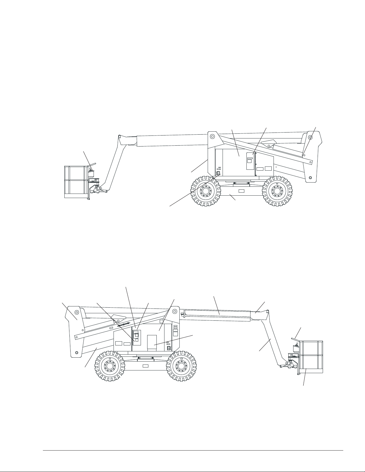
Component Identication
Chapter 2 – Specications
Upper Controls
Floating
Turret
Lower
Controls
Emergency
Lowering Knob
Hydraulic Fluid
Filter
Battery Disconnect Switch
Battery
Engine
Rear Front
Right Side
Fuel Tank
Chassis
Main Boom
Hydraulic Fluid
Tank
Steer Wheels
Tip Boom
Emergency
Lowering Knob
Platform
Operator’s
Manual
Jib
Riser
Boom
Steer Wheels
Front
Rear
Boom
Platform
Foot Switch
Left Side
AB60J – 0181972 3
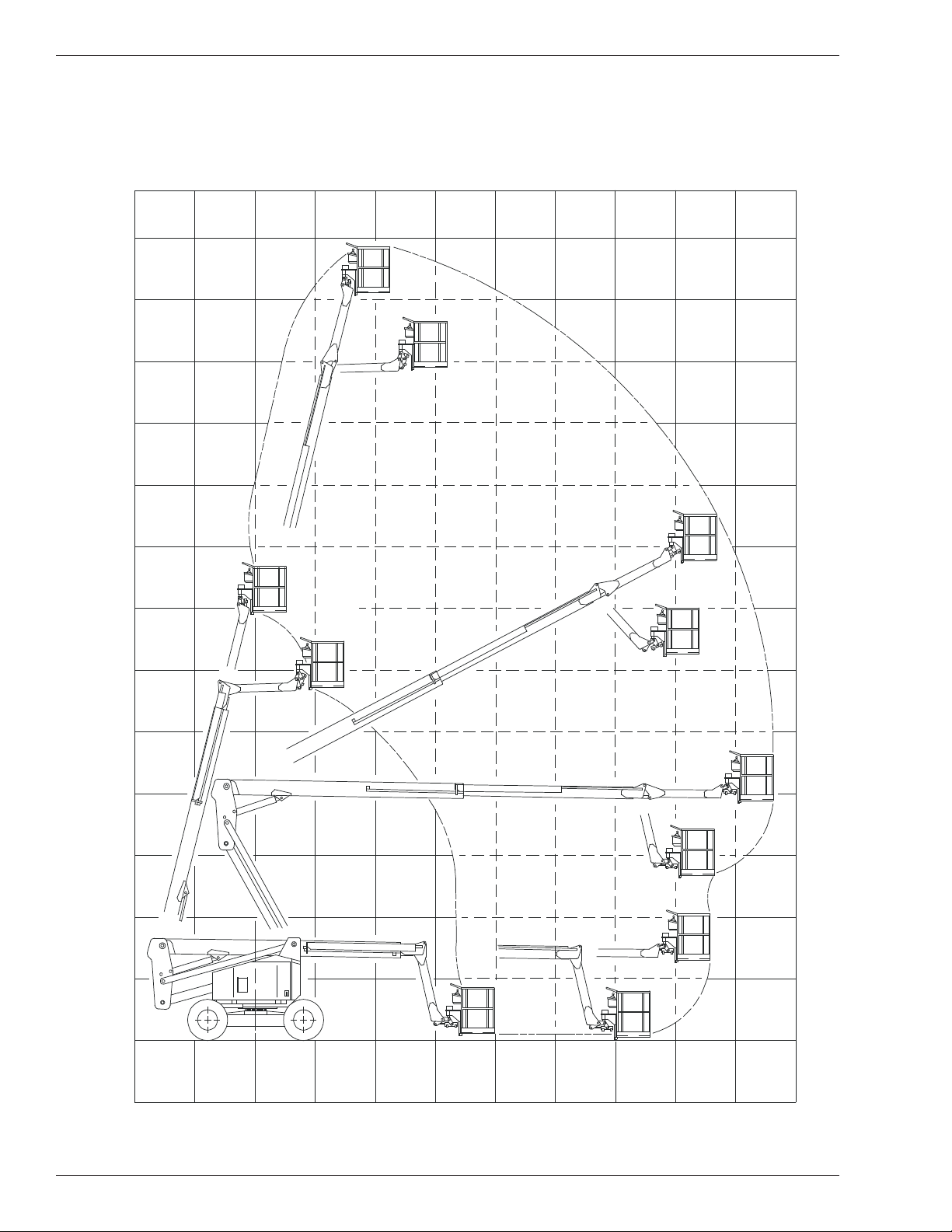
Working Envelope
Feet
(Meters)
65
(19.8)
60
(18.3)
55
(16.8)
50
(15.2)
45
(13.7)
40
(12.2)
35
(10.7)
30
(9.1)
25
(7.6)
20
(6.1)
15
(4.6)
10
(3.0)
5
(1.5)
0
5
(1.5)
4 AB60J – 0181972
10
(3.0)
(1.5)
05
5
(1.5)
10
(3.0)
15
(4.6)
20
(6.1)
25
(7.6)
30
(9.1)
35
(10.7)
40
(12.2)
45
(13.7)

General Specications
Chapter 2 – Specications
Aerial Platform
Working height 66′ (20.11 m)
Maximum platform height 60′ (18.29 m)
Horizontal reach 43′ 1″ (13.1 m)
Main boom elevation -1° to +75°
Turntable rotation 360° continuous
Turning radius, inside
Two wheel drive 8′ 3″ (2.5 m)
Four wheel drive 17′ 2 ½″ (5.24 m)
Wheelbase 8′ (2.4 m)
Ground clearance 1′ (30 cm)
Tailswing
Stowed 5′ (1.54 m)
Working 0′ (0 m)
Maximum wheel load 12,500 lbs (5,670 kg)
Maximum ground pressure 82 psi (5.76 kg/cm²)
Weight, EVW approximate 24,800 lbs (11,249 kg)
Stowed width 7′ 11 ½″ (2.4 m)
Stowed length 29′ 2″ (8.9 m)
Stowed height 8′ 3″ (2.5 m)
Platform
Dimensions
Standard steel 39″ x 96″ (99 cm x 243 cm)
Rated work load 500 lb (227 kg)
Optional steel 30″ x 60″ (76 cm x 152 cm)
Rated work load 500 lb (227 kg)
Optional aluminum 30″ x 60″ (76 cm x 152 cm)
Rated work load 500 lb (227 kg)
Optional aluminum 30″ x 96″ (76 cm x 243 cm)
Rated work load 500 lb (227 kg)
Rotation 90° CW to 90° CCW
Maximum number of occupants 2 people
Optional AC generator 120 V, 2 kw
Optional AC generator 220 V, 50 Hz
Function Speed
Turntable rotation, 360 degrees 85 to 95 seconds
Main boom
Up 40 to 45 seconds
Down 40 to 45 seconds
Extend 30 to 38 seconds
Retract 30 to 38 seconds
Riser boom
Up 24 to 30 seconds
Down 16 to 20 seconds
Jib boom
Up 9 to 12 seconds
Down 7 to 11 seconds
Platform rotation, 180 degrees 16 to 20 seconds
Drive
4x4 and 4x2
High, booms down/retracted 3.2 mph (5.1 km/h)
Mid, booms down/retracted 1.9 mph (3.1 km/h)
Low, booms up/extended 0.6 mph (1 km/h)
Drive System
Standard Four wheel drive
Optional Two wheel drive
Gradeability – theoretical 20%
Tires
Foam lled 15-19.5, 12 ply
Highway tread
4x2 15-19.5, 12 ply
4x4 15-19.5, 14 ply
Flotation 40x19-19.5
Electrical System
Voltage 12 V DC negative chassis ground
Source One - 12 V 550 CCA battery
Fluid recommended distilled water
Hydraulic System
Maximum pressure 3,000 psi (20,700 kPa)
Reservoir capacity 25 US gal (94.6 l)
System capacity 35 US gal (132.5 l)
Maximum operating temperature 200°F (93°C)
Hydraulic uid recommended
Above 10°F (-12°C) Mobil DTE-13M (ISO VG32)
Below 10°F (-12°C) Mobil DTE-11M (ISO VG15)
Engine
Diesel Cummins B3.3
Cummins 4B3.9
Hatz 4L31C
Gasoline, LPG or Duel Fuel Continental TM27
Ford LRG 423
Ford LRG 425
General Motors 2.4
General Motors 3.0
Fuel Tank Capacity
Gasoline or diesel 40 US gal (151.4 l)
LPG 43.5 lb (20 kg)
Ambient Air Temperature Operating Range
Fahrenheit 0°F to 110°F
Celsius -18°C to 43°C
Maximum Wind Speed
Gust or steady 28 mph (45 km/h)
AB60J – 0181972 5

Chapter 2 – Specications
Engine Specications
Engine CID Fuel Grade Coolant
Operating
Temperature
Gasoline
Unleaded gasoline
85 octane
1
50% Water
50% Antifreeze
180°F to 202°F
2
81°C to 94°C
Continental
TM27
79.3 cu. in.
(1.3 liter)
(motor method)
3
Gas Processors
LPG
Association
Standard 2140
1
Category: special
duty propane
Diesel
ASTM No. 2D fuel
with a minimum
Cummins
B3.3
199 cu. in.
(3.26 liter)
Cetane number of
3
40.1 For operating
50% Water
50% Antifreeze
140°F to 212°F
2
60°C to 100°C
temperatures below
32°F (0°C) use
winterized No. 2D.
Diesel
ASTM No. 2D fuel
with a minimum
Cummins
4B3.9
239 cu. in.
(3.9 liter)
Cetane number of
3
40.1 For operating
50% Water
50% Antifreeze
140°F to 212°F
2
60°C to 100°C
temperatures below
32°F (0°C) use
winterized No. 2D.
Gasoline
Unleaded gasoline
85 octane
1
50% Water
50% Antifreeze
160°F to 190°F
2
71°C to 88°C
Ford
LRG 423
79.3 cu. in.
(1.3 liter)
(motor method)
3
Gas Processors
LPG
Association
Standard 2140
1
Category: special
duty propane
Note 1: Refer to the engine manufacturers manual for specic fuel recommendations and specications.
Oil
Capacity
6 US qt
(5.7 liter)
3
2 gal (7.5 liter)3
total
1.6 qt (1.5 liter)
Low to High
2.5 gal
(9.4 liter)
3
4 US qt
(3.8 liter)
3
Oil Grade
SE, SF,
SE/CD
SF/CD
API CH4
3
5W-30
CE/SF
CD/SF
Gasoline
API: SH
SG only if
SH is not
available
LPG
SG or SH
API:
3
3
SAE
3
API:
3
3
3
Note 2: Refer to the engine manufacturers manual for specic coolant recommendations and specications.
Note 3: Refer to the engine manufacturers manual for specic lubricating oil recommendations and specications.
6 AB60J – 0181972

Chapter 2 – Specications
Engine CID Fuel Grade Coolant
Operating
Temperature
Gasoline
Unleaded 87 or 89
octane.1 Do not use
gasoline blends with
Ford
LRG 425
153 cu. in.
(2.5 liter)
more than 10% ethanol by volume octane
3
index of 87 or 89.
50% Water
50% Antifreeze
195°F to 220°F
2
91°C to 104°C
LPG
HD-5 USA1 EN589
European
Gasoline
General
Motors
2.4 and 3.0
150 cu. in.
(2.4 liter)
Unleaded 87 octane
3
LPG
HD-5
1
1
50% Water
50% Antifreeze
176°F to 183°F
2
80°C to 84°C
Diesel
DIN 51 601
(February 1986)
BS 2869: A1 and
1
A2 (with A2 refer
to manual about
Hatz
4L31C
sulfur content)
ASTM D 975-88:
1-D and 2-D
For operating
1
Air No gauge
1
temperatures
below 32°F (0°C)
use winter grade
diesel
Note 1: Refer to the engine manufacturers manual for specic fuel recommendations and specications.
Oil
Capacity
4.5 US qt
(4.26 liter)
3
With lter:
1.12 US gal
(4.5 liter)
3
Without lter:
1.18 US gal
(4.25 liter)
3
12.3 US qt
(13 liter)
3
Oil Grade
API: SH
3
or SJ
ILSAC
3
GF-4
API: CD,
CE, CF43
3
SHPD
CCMC:
D4, D5,
PD1
3
(PD2)
Note 2: Refer to the engine manufacturers manual for specic coolant recommendations and specications.
Note 3: Refer to the engine manufacturers manual for specic lubricating oil recommendations and specications.
AB60J – 0181972 7
Chapter 2 – Specications
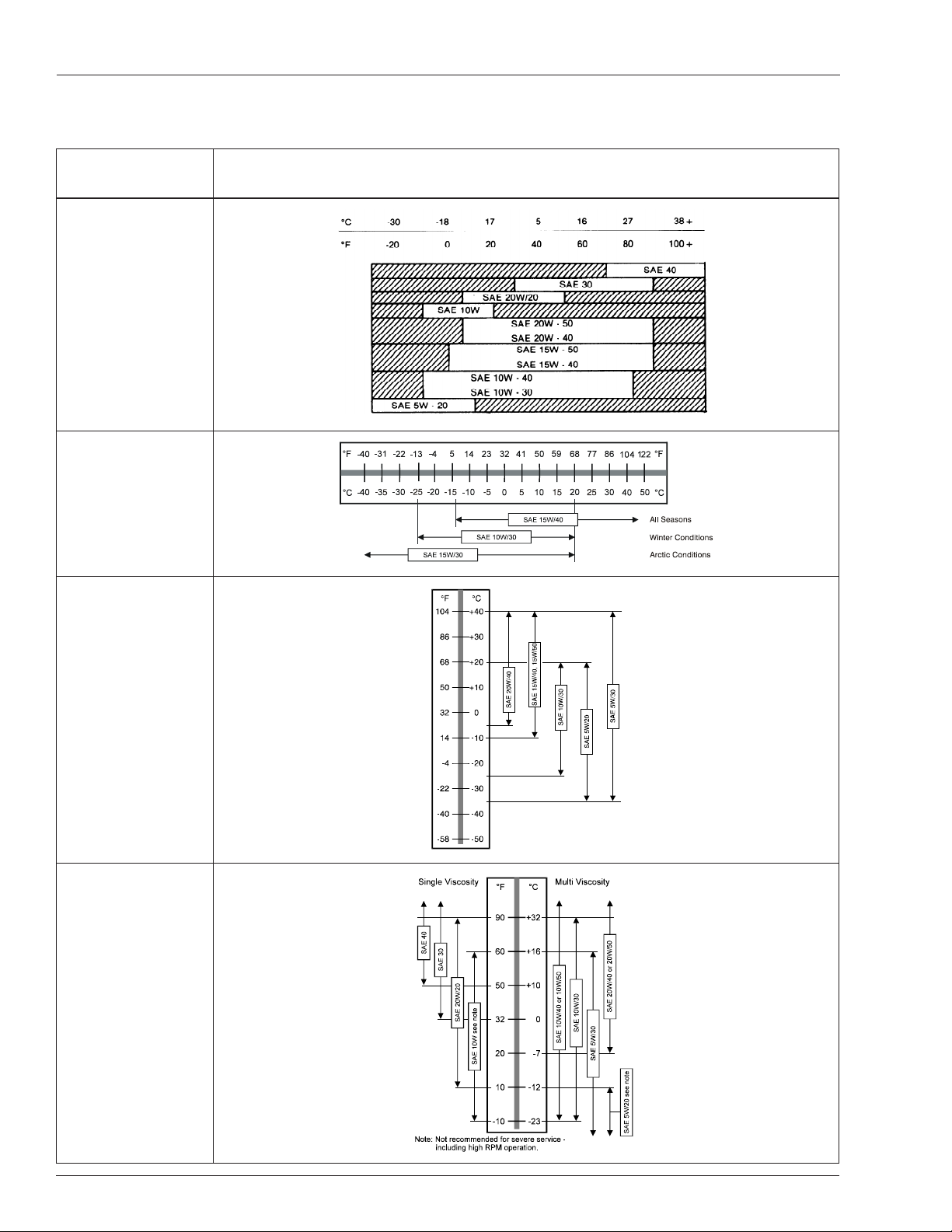
Engine Oil Viscosity
Engine Oil Viscosity
Continental
TM27
Cummins
B3.3
Cummins
4B3.9
Ford
LRG 423
8 AB60J – 0181972
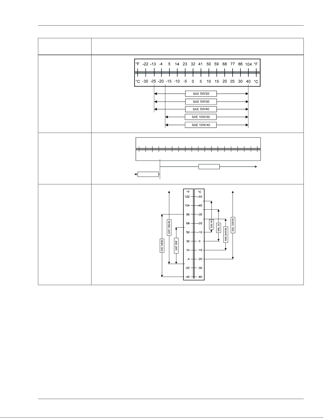
Engine Oil Viscosity
°F
°F
-4 0
-3 1
-2 2
-1 3
-4
5
14
23 324150 59 68 77 86 104
122
°C
°C
-4 0
-3 5
-3 0 - 25 -2 0 -15 - 10-50
10
15 2 0 253040 5 0
5
SA E 5W /3 0
SA E 0W /3 0
Ford
LRG 425
General Motors
2.4 and 3.0
Chapter 2 – Specications
Hatz
4L31C
AB60J – 0181972 9

Chapter 2 – Specications
10 AB60J – 0181972
Chapter 3 – Safety
Voltage Range
(Phase to Phase)
Minimum Safe Approach Distance
Feet Meters
0 to 300V Avoid Contact
Over 300V to 50kV 10 3.05
Over 50kV to 200kV 15 4.60
Over 200kV to 350Kv 20 6.10
Over 350kV to 500kV 25 7.62
Over 500kV to 750kV 35 10.67
Over 750kV to 1000kV 45 13.72
Knowledge of the information in this manual, and proper
training, provide a basis for safely operating the aerial platform. Know the location of all controls and how they operate to act quickly and responsibly in an emergency.
Safety devices reduce the likelihood of an accident.
Never disable, modify, or ignore any safety device.
Safety alerts in this manual indicate situations where
accidents may occur.
If any malfunction, hazard or potentially unsafe condition
relating to capacity, intended use, or safe operation is suspected, stop aerial platform operation and seek assistance.
The operator bears ultimate responsibility for following
all manufacturer’s instructions and warnings, regulations
and safety rules of their employer and/or any state or
federal law.
Electrocution Hazards
The aerial platform is made of metal components and is
not insulated. Regard all conductors as energized. Do
not operate outside during a thunderstorm.
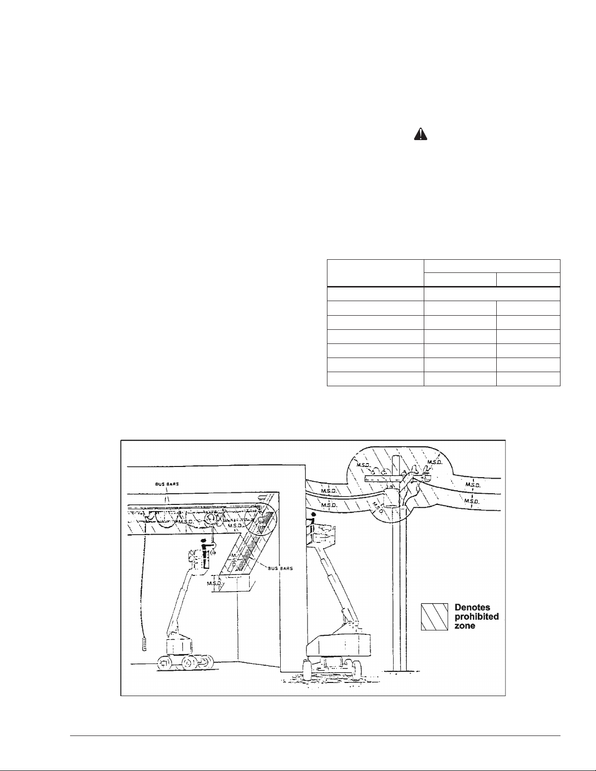
Minimum Safe Approach Distance
Minimum safe approach distances to energized power
lines and their associated parts must be observed while
operating the aerial platform.
Danger
The aerial platform is not electrically insulated. Death
or serious injury will result from contact with, or inadequate clearance from, an energized conductor.
Do not go closer than the minimum safe approach
distance as dened by ANSI.
ANSI publications dene minimum distances that must
be observed when working near bus bars and energized
power lines. Table 1 and Figure 3 are reprinted courtesy
of Scaffold Industry Association, ANSI/SIA A92.5.
AB60J – 0181972 11
Table 1 – Minimum Safe Approach Distance
Figure 3 – Minimum Safe Approach Distance

Chapter 3 – Safety
Prestart Inspection
Perform a prestart inspection before each shift as described in Chapter 7. Do not use the aerial platform on
the job unless you are trained and authorized to do so.
Work Place Inspection and Practices
Do not use the aerial platform as a ground connection
when welding.
The welding ground clamp must be attached to the
same structure that is being welded.
Electrical current ow can be very intense, causing
serious internal damage to some components.
Inspect the area before and during aerial platform use.
The following are some potential hazards that may be in
the work place:
Debris
Slopes
Drop-offs or holes
Bumps and oor obstructions
Overhead obstructions
Unauthorized persons
High voltage conductors
Wind and weather conditions
Inadequate surface and support to withstand load
forces applied by the aerial platform in all operating
congurations
Before using the aerial platform in any hazardous (classied) location, make certain it is approved and of the
type required by ANSI/NFPA 505 for use in that particular
location.
Know and understand the job site trafc-ow patterns and
obey the agmen, road signs and signals.
While operating the aerial platform, a good safety prac-
tice is to have qualied personnel in the immediate work
area to:
Help in case of an emergency
Operate emergency controls as required
Watch for loss of control by platform operator
Warn the operator of any obstructions or hazards that
may not be obvious to them
Watch for soft terrain, sloping surfaces, drop-offs, etc.
where stability could be jeopardized
Watch for bystanders and never allow anyone to be
under, or to reach through the booms while operating
the aerial platform
booms or platform. Allow sufcient room and time
to stop movement to avoid contact with structures
or other hazards.
Always look in the direction of movement.
Drive with care and at speeds compatible with the
work place conditions.
Use caution when driving over rough ground, on
slopes and when turning.
Do not engage in any form of horseplay or permit rid-
ers any place other than in the platform.
Secure all accessories, containers, tools and other materials in the platform to prevent them from accidentally
falling or being kicked off the platform. Remove all objects
that do not belong in or on the aerial platform.
Never steady the platform by positioning it against another platform.
Warning
The potential for an accident increases when operating an aerial platform that is damaged or malfunctioning. Death or serious injury could result from such
accidents. Do not operate the aerial platform if it is
damaged or malfunctioning.
Do not operate the aerial platform if it is damaged or not
functioning properly. Qualied maintenance personnel
must correct the problem before putting the aerial platform
back into service.
Operation
Use three points of support when entering or exiting the
platform. For example, use two hands and one foot when
climbing into the platform.
Never cover the platform oor grating or otherwise obstruct your view below. Make sure the area below the
platform is free of personnel before lowering.
Keep both feet positioned rmly on the platform oor.
Operate the controls slowly and deliberately to avoid
jerky and erratic operation.
Always stop the controls in neutral before going in the
opposite direction.
Do not dismount while the aerial platform is in motion or
jump off the platform.
Danger
Pinch points may exist between moving components.
Death or serious injury will result from becoming
Properly stow the aerial platform and secure it against
unauthorized operation at the end of each work day,
before transporting, or if it is left unattended.
trapped between components, buildings, structures,
or other obstacles. Make sure there is sufcient clearance around the machine before moving the chassis,
12 AB60J – 0181972

Chapter 3 – Safety
Tip-Over and Falling Hazards
Operate the aerial platform only on a rm, at, level surface capable of withstanding all load forces imposed by
the aerial platform in all operating conditions. Refer to
the General Specications chart for the maximum wheel
load and ground pressure. Raise the booms only when
the aerial platform is on level ground.
Danger
The aerial platform can tip over if it becomes unstable.
Death or serious injury will result from a tip-over accident. Do not drive or position the aerial platform for
elevated use near any drop-off, hole, slope, soft or
uneven ground, or other tip-over hazard.
All platform occupants must wear a fall restraint device
connected to a lanyard anchor point.
It is best not to transfer from the platform to another
structure or from the structure to the platform, unless
that is the safest way to do the job. Judge each situation
separately taking the work environment into account. If
it is necessary to transfer from the platform to another
structure the following guidelines apply:
1. Where possible, place the platform over a roof or
walking structure to do the transfer.
2. Transfer your anchorage from one structure to the
other before stepping across.
3. Remember that you might be transferring to a structure where personal fall arrest is required.
4. Use the platform entrance, do not climb over or
through the guardrails.
Do not operate the aerial platform in windy or gusty conditions. Do not add anything to the aerial platform that will
increase the wind loading such as billboards, banners,
ags, etc.
Never operate the aerial platform without all parts of the
guardrail system in place and the gate closed. Make
sure that all protective guards, cowlings, and doors are
securely fastened.
Do not exceed the platform capacity as indicated on the
platform rating placard on the platform. Do not carry loads
that extend beyond the platform guardrails without prior
written consent from Snorkel.
Do not operate the aerial platform from trucks, trailers, rail-
way cars, oating vessels, scaffolds, or similar equipment
unless the application is approved in writing by Snorkel.
Do not use the aerial platform as a crane, hoist, jack, or
for any purpose other than to position personnel, tools,
and materials.
Do not climb on the guardrails or use ladders, planks,
or other devices to extend or increase the work position
from the platform.
Take care to prevent rope, electrical cords, and hoses,
etc., from becoming caught in or on the aerial platform.
If the platform or booms becomes caught on an ad-
jacent structure or other obstacle and is prevented
from normal motion, reverse the control to free the
platform.
If control reversal does not free the platform, evacuate
the platform before attempting to free it.
Electrical System
Charge the battery in a well-ventilated area free of ame,
sparks, or other hazards that might cause re or explo-
sion.
Do not operate any of the aerial platform functions while
the battery charger is plugged in.
Warning
Batteries give off hydrogen and oxygen that can
combine explosively. Death or serious injury could
result from a chemical explosion. Do not smoke or
permit open ames or sparks when checking the
batteries.
Battery acid can damage the skin and eyes. Serious
infection or reaction could result if medical treatment
is not given immediately. Wear face and eye protection when working near the batteries.
Batteries contain sulfuric acid that can damage your
eyes or skin on contact.
Wear a face shield, rubber gloves, and protective
clothing when working around batteries.
If acid contacts your eyes, ush immediately with clear
water and get medical attention.
If acid contacts your skin, wash off immediately with
clear water.
Hydraulic System
The hydraulic system contains hoses with hydraulic uid
under pressure.
Danger
Hydraulic uid escaping under pressure can have
enough force to inject uid into the esh. Serious
infection or reaction will result if medical treatment is
not given immediately. In case of injury by escaping
hydraulic uid, seek medical attention at once.
Do not place your hand or any part of your body in front
of escaping hydraulic uid. Use a piece of cardboard or
wood to search for hydraulic leaks.
AB60J – 0181972 13

Chapter 3 – Safety
Engine and Fuel Handling Precautions
Refer to the engine manufacturer’s Operator’s Manual for
complete information on safe engine operation, mainte-
nance, and specications.
Danger
Engine exhaust contains carbon monoxide, a poi-
sonous gas that is invisible and odorless. Breathing
engine exhaust fumes will cause death or serious
illness. Do not run the engine in an enclosed area or
indoors without adequate ventilation.
Operate dual fuel machines on LPG fuel when indoors to
reduce exhaust fumes and carbon monoxide.
Be careful not to run the diesel fuel tank empty. Bleed the
fuel system if air enters the lines between the tank and
the injection pump.
Allow the engine to return to idle before shutting the
engine off.
Do not smoke or permit open ames while fueling or near
fueling operations.
Never remove the fuel cap or ll the fuel tank while the
engine is running or hot. Never allow fuel to spill on hot
machine components.
Do not overll the fuel tank. Allow room for expansion.
Clean up spilled fuel immediately.
Tighten the fuel tank cap securely. If the fuel cap is lost,
replace it with an approved cap from Snorkel. Use of a
non-approved cap without proper venting may result in
pressurization of the tank.
Never use fuel for cleaning purposes.
For diesel engines, use the correct fuel grade for the
operating season.
Caution
Engine coolant escaping under pressure may cause
serious burns. Shut the engine off and let it cool
before removing the radiator cap.
Let the engine and radiator cool before adding coolant.
Placards and Decals
The aerial platform is equipped with placards and decals
that provide instruction for operation and accident prevention. Do not operate the aerial platform if any placards or
decals are missing or not legible.
Maintain control of the fuel ller nozzle when lling the
tank. Spilled fuel is a potential re hazard.
14 AB60J – 0181972
Chapter 4 – Safety Devices
This aerial work platform is manufactured with safety
devices, placards, and decals to reduce the likelihood
of an accident.
For the safety of all personnel, do not disable, modify,
or ignore any safety device.
Safety devices are included in the daily prestart
inspection.
Warning
The potential for an accident increases when safety
devices do not function properly. Death or serious
injury could result from such accidents. Do not alter,
disable, or override any safety device.
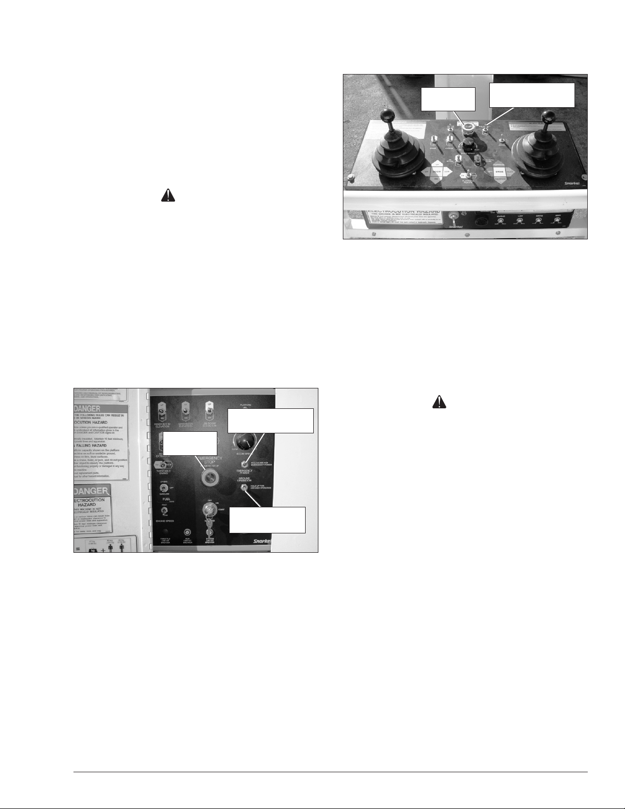
Emergency
Stop Button
Engine/Emergency
Power Switch
Figure 4.2 – Upper Controls
If any safety devices are defective, remove the aerial
platform from service until qualied maintenance personnel can make repairs.
Emergency Stop Controls
There is an emergency stop control at the lower and
upper controls.
At the lower controls, the emergency stop is a two-posi-
tion red push button (refer to Figure 4.1).
Engine/Emergency
Power Switch
Emergency
Stop Button
Ground
Operation Switch
Figure 4.1 – Lower Controls
Push the emergency stop button inward to disconnect
power to the upper control circuits.
Pull the button outward to restore power.
Emergency Power System
The emergency power system includes a back-up pump,
motor, and battery. Use this system to operate the boom
and turntable functions to lower the platform if the main
power system fails due to engine or pump failure.
Caution
The emergency power system is for emergency lowering and stowing only. The length of time the pump
can be operated depends on the capacity of the battery. Do not use this system for normal operation.
Hold the engine/emergency power switch (refer to
Figure 4.1 and 4.2) downward to activate the emergency power system.
Release the switch to disengage the emergency
power system.
The length of time the pump can be operated depends
on the capacity of the battery.
Push the emergency stop button inward to disconnect
power to all control circuits.
Emergency Lowering Knobs
The emergency lowering knobs may be used to lower
the booms if the engine will not start and the emergency
Pull the button outward to restore power.
Note
The lower controls override the upper controls. If the up-
power system will not work.
There is a knob to lower the riser boom and one to lower
the main boom.
per control emergency stop button is engaged, the lower
The riser boom knob (refer to Figure 4.3) is inside the
controls can still be used to operate the aerial platform.
rear of the turntable.
At the upper controls, the emergency stop is a two-posi-
tion red push button (refer to Figure 4.2).
AB60J – 0181972 15
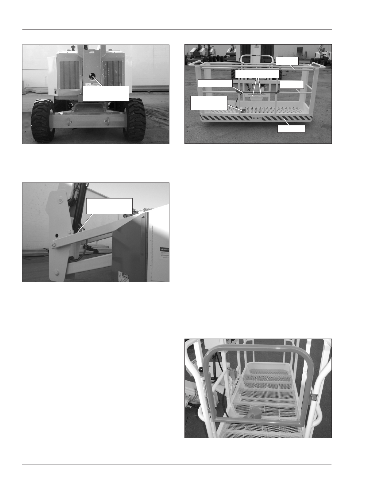
Chapter 4 – Safety Devices
Emergency
Lowering Knob
Gravity Gate
Platform Foot
Switch
Top Rail
Lanyard Anchors
Mid Rail
Toeboard
Figure 4.3 – Rear of Turntable
The main boom knob (refer to Figure 4.4) is behind
the oating turret.
Emergency
Lowering Knob
Figure 4.4 – Floating Turret at Front of Turntable
Ground Operation Switch
The ground operation switch (refer to Figure 4.1) prevents
boom and platform movement if a control switch on the
lower control panel is accidentally moved.
Hold the switch upward to operate the machine from the
lower controls.
Figure 4.5 – Platform
The foot switch must be engaged and a control must be
moved to operate the boom, drive, and/or platform from
the upper controls.
Guardrails
The guardrails (refer to Figure 4.5) help protect personnel
from falling off the platform.
The guardrail system includes:
A top rail
A mid rail
A gravity gate or optional swinging gate
Optional side entry gravity gate
Toeboards around the sides of the platform.
The gravity gate(s) allow for access to the platform and
close automatically after entering or exiting the platform.
After entering the platform check to make sure the gates
are fully lowered and even with the mid rail.
The optional swinging gate (refer to Figure 4.6) allows
for access to the platform. The gate must be securely
latched except when personnel are entering or leaving
the platform.
Platform Foot Switch
Step down on the platform foot switch (refer to Figure 4.5)
to activate the upper controls.
Figure 4.6 – Platform
16 AB60J – 0181972
Chapter 4 – Safety Devices
Lanyard Anchors
Two lanyard anchors for fall restraint anchorage are provided below the upper controls at the front of the platform
(refer to Figure 4.5).
Note
The lanyard anchors are not designed for lifting or tying
the machine down.
All personnel in the platform must connect their fall
restraint device to a lanyard anchor before raising
the platform.
Attach only one fall restraint device to each lanyard
anchor.
Do not use the aerial platform for personal fall arrest
anchorage.
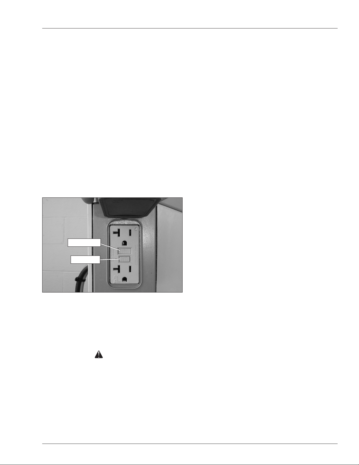
Ground Fault Circuit Interrupter
The electrical power outlet at the platform (refer to Figure
4.7) contains a ground fault circuit interrupter (GFCI) to
provide protection for personnel.
Engine Protection Systems
A constant alarm will sound to warn against high engine
temperature or low oil pressure.
The engine will shut-down
if the operating temperature exceeds a preset level
or if the oil pressure is too low for safe operation.
High Engine Temperature Alarm
If the coolant in a Continental, Cummins, Ford or GM
engine exceeds the engine operating temperature an
alarm will sound and the engine will shut off.
If the oil in a Hatz engine exceeds the engine operating
temperature an alarm will sound and the engine will shut
off. Any time there is no alternator current being produced,
an alarm will sound and the engine will shut off. This prevents high engine temperature if the fan belt breaks.
Do not restart the engine until the condition that caused
the overheating has been corrected.
Low Oil Pressure Alarm
The low oil pressure alarm sounds when the engine oil
pressure is near the lower limit for safe engine operation.
If the alarm sounds, lower the platform to the ground and
then turn the engine off.
Reset Button
Test Button
Figure 4.7 – Electrical Power Outlet
Tilt Alarm
If the aerial platform chassis is out of level more than ve
degrees when the main boom is raised or extended, or
when the riser boom is raised, an alarm will sound. The
tilt alarm is located at the upper control panel.
Danger
The aerial platform can tip over if it becomes unstable.
Death or serious injury will result from a tip-over accident. Do not drive or position the aerial platform
for elevated use near any drop-off, hole, slope, soft
or uneven ground, or other tip-over hazard.
Completely lower the booms and then drive to a level
surface when the tilt alarm sounds.
The tilt alarm is for added protection and does not
justify operating on anything other than rm, at, level
surfaces.
If the engine oil pressure falls below a safe operating
value the engine will shut off.
The engine can be restarted with low oil pressure,
but it will only run for a few seconds before it shuts
off again.
Do not restart the engine until the condition that
caused the low oil pressure has been corrected.
Horn
An optional horn may be used to warn personnel on the
ground. The horn is on the upper control box.
The horn is operational when the emergency stop button
and the start switches are both on, at the lower and the
upper controls.
All Motion Alarm
An optional all motion alarm may be provided on the machine. The alarm sounds, in short beeps, anytime the the
machine fuctions are being operated. The alarm is used
to warn personnel in the work area to stand clear.
Flashing Lights
The optional ashing lights mounted on the top of the
cowling on each side of the machine (refer to Figure 4.8)
may be used to warn personnel that the aerial platform
is in the area.
AB60J – 0181972 17

Chapter 4 – Safety Devices
Flashing Light
Figure 4.8 – Flashing Lights
The lights ash at about one ash per second when the
engine is running.
Driving Lights
The optional headlights and blinking tail lights may be
used to help improve visibility while driving the aerial
platform and help others see it too.
Platform Work Lights
The optional platform work lights may be used to help
improve visibility while working aloft in dimly lit areas.
The platform work lights are located on the top rail of
the platform, one on each side of the upper control
panel.
Do not use the platform work lights to drive on public
roadways.
Bumpguard System
The optional bumpguard system is a spring mounted
padded railing below the platform. There are two infrared lights mounted along the bottom of the platform next
to two infrared sensitive switches. The lights shine on
reectors on the bumpguard system and are reected
back to the switches.
If the bumpguard comes into contact with a stationary
object, the bumpguard moves and one or both of the
light beams is broken, immediately stopping all platform
movement.
The headlights are located on the top of the front
cowling.
The tail lights are mounted on the sides of the rear
cowling.
Do not use the driving lights to drive on public road-
ways.
18 AB60J – 0181972
Chapter 5 – Gauges and Displays
The aerial platform is equipped with several gauges to
monitor the condition of the machine before and during
operation.
Hour Meter
The hour meter is located on the lower control panel
(refer to Figure 5.1). It measures the accumulated engine
operating time.
Hour Meter
Figure 5.1 – Lower Controls
Engine Temperature Gauge
The engine temperature gauge is located on the engine
gauge panel above the lower controls (refer to Figure
5.2).
Ammeter – Continental, Cummins, Ford
and Hatz Engines
The ammeter is located on the engine gauge panel above
the lower controls (refer to Figure 5.2). The ammeter
displays the level of current ow from the alternator to
the batteries.
After the engine has been running for a few minutes
under normal operating conditions, the ammeter
gauge indicator should read “0.”
Voltmeter – General Motors Engines
The voltmeter is located on the engine gauge panel above
the lower controls (refer to Figure 5.2). The voltmeter
displays battery voltage.
After the engine has been running for a few minutes
under normal operating condition, the voltmeter
should indicate between 12.5 and 14 volts.
Engine Air Filter Gauge
The air lter gauge (refer to Figure 5.2) is located on the
engine gauge panel above the lower controls.
Note
Machines equipped with a Hatz engine do not have an
air lter that is accessible to the operator.
The air lter gauge measures the air pressure between
the intake manifold and the air lter.
Air Filter
Gauge
Engine Temperature Gauge
Reset Button
Ammeter – Continental, Cummins, Ford,
and Hatz Engines
Voltmeter – General Motors Engines
Figure 5.2 – Engine Gauge Panel
The gauge on liquid cooled engines shows the tem-
perature of the water and antifreeze mixture in the
engine block.
The gauge on air cooled engines shows the tempera-
ture of the engine oil as the oil leaves the lter.
Note
Machines equipped with a Hatz engine do not have a
temperature gauge. However, Hatz engines do have temperature sensors and automatic temperature shut-offs.
The yellow indicator disk inside the sight glass stays
at its highest level when the engine is turned off.
When the yellow indicator disk reaches the red area,
it’s time to change the lter element.
After changing the lter, press the reset button to reset
the indicator disk to the bottom of the sight glass.
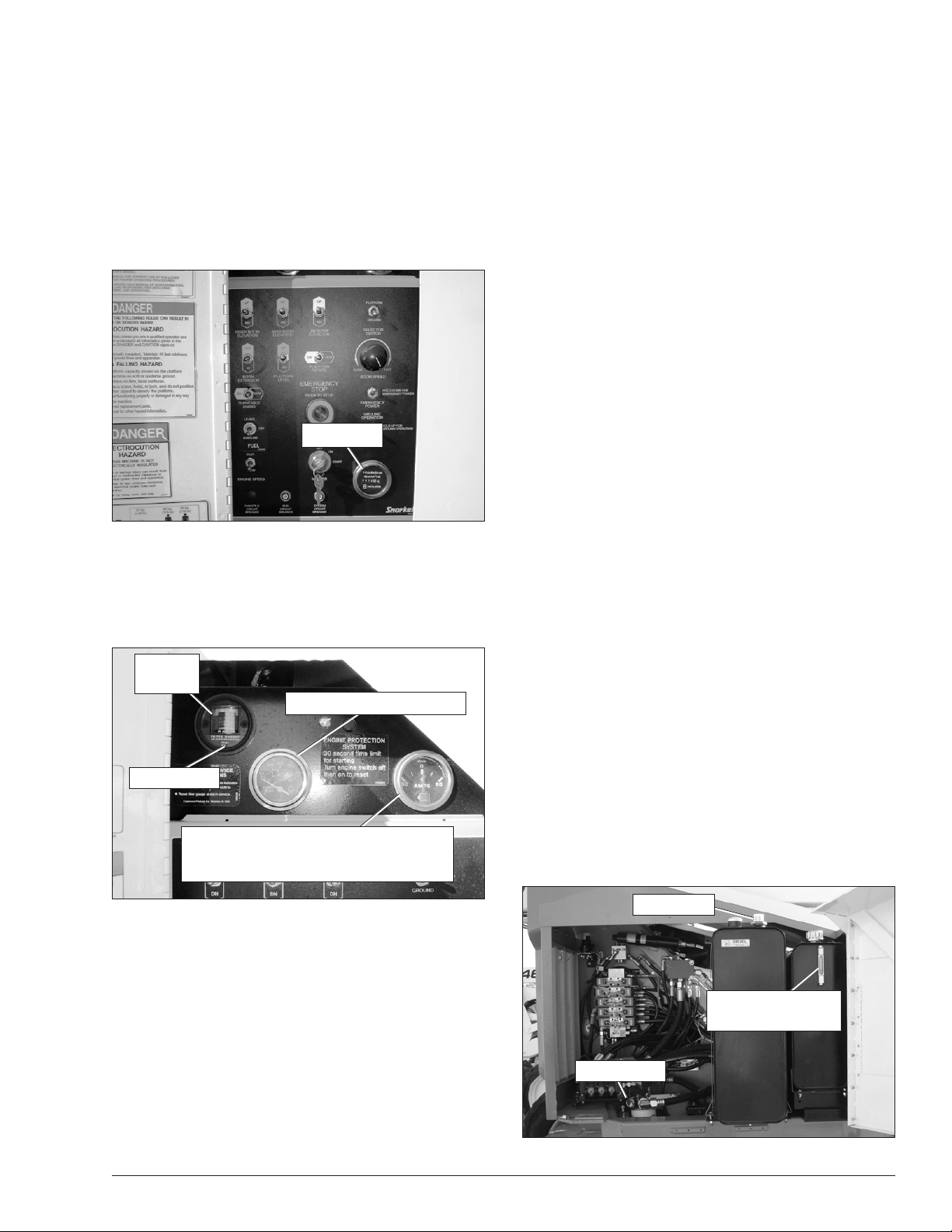
Fuel Gauge
The fuel gauge is located on top of the diesel or gasoline
tank (refer to Figure 5.3). Access the gauge by opening
the door on the right side of the chassis.
Fuel Gauge
Fluid Level and
Temperature Gauge
Filter Gauge
Figure 5.3 – Fuel Tank
AB60J – 0181972 19
 Loading...