

Page 1
Operating/Safety Instructions
Consignes de fonctionnement/sécurité
Instrucciones de funcionamiento
y seguridad
4225
4235
IMPORTANT: IMPORTANT : IMPORTANTE:
Read Before Using Lire avant usage Leer antes de usar
Consumer Information
Renseignement des consommateurs
Información para el consumidor
Toll Free Number: Appel gratuit : Número de teléfono gratuito:
1-877-SKIL999 (1-877-754-5999) http://www.skiltools.com.
For English Parlez-vous français? ¿Habla español?
See page 2 Voir page 12 Ver página 22
SM 2610995772 8/00 9/14/00 8:53 AM Page 1
Page 2

-2-
Work Area
Keep your work area clean and well lit.
Cluttered benches and dark areas invite
accidents.
Do not operate power tools in explosive
atmospheres, such as in the presence of
flammable liquids, gases, or dust. Power
tools create sparks which may ignite the dust
or fumes.
Keep by-standers, children, and visitors
away while operating a power tool.
Distractions can cause you to lose control.
Electrical Safety
Double Insulated tools are equipped with a
polarized plug (one blade is wider than the
other.) This plug will fit in a polarized outlet
only one way. If the plug does not fit fully
in the outlet, reverse the plug. If it still does
not fit, contact a qualified electrician to
install a polarized outlet. Do not change the
plug in any way. Double Insulation
eliminates the need for the three wire
grounded power cord and grounded power
supply system. Before plugging in the tool, be
certain the outlet voltage supplied is within the
voltage marked on the nameplate. Do not use
“AC only” rated tools with a DC power supply.
Avoid body contact with grounded
surfaces such as pipes, radiators, ranges
and refrigerators. There is an increased risk
of electric shock if your body is grounded. If
operating the power tool in damp locations is
unavoidable, a Ground Fault Circuit Interrupter
must be used to supply the power to your
tool. Electrician’s rubber gloves and footwear
will further enhance your personal safety.
Don't expose power tools to rain or wet
conditions. Water entering a power tool will
increase the risk of electric shock.
Do not abuse the cord. Never use the cord
to carry the tools or pull the plug from an
outlet. Keep cord away from heat, oil,
sharp edges or moving parts. Replace
damaged cords immediately. Damaged
cords increase the risk of electric shock.
When operating a power tool outside, use
an outdoor extension cord marked "W-A"
or "W." These cords are rated for outdoor use
and reduce the risk of electric shock. Refer to
“Recommended sizes of Extension Cords” in
the Accessory section of this manual.
Personal Safety
Stay alert, watch what you are doing and
use common sense when operating a
power tool. Do not use tool while tired or
under the influence of drugs, alcohol, or
medication. A moment of inattention while
operating power tools may result in serious
personal injury.
Dress properly. Do not wear loose clothing
or jewelry. Contain long hair. Keep your
hair, clothing, and gloves away from
moving parts. Loose clothes, jewelry, or long
hair can be caught in moving parts. Keep
handles dry, clean and free from oil and
grease.
Avoid accidental starting. Be sure switch
is “OFF” before plugging in. Carrying tools
with your finger on the switch or plugging in
tools that have the switch “ON” invites
accidents.
Remove adjusting keys or wrenches before
turning the tool “ON”. A wrench or a key
that is left attached to a rotating part of the
tool may result in personal injury.
Do not overreach. Keep proper footing and
balance at all times. Proper footing and
balance enables better control of the tool in
unexpected situations.
Use safety equipment. Always wear eye
protection. Dust mask, non-skid safety
shoes, hard hat, or hearing protection must be
used for appropriate conditions.
Tool Use and Care
Use clamps or other practical way to
secure and support the workpiece to a
stable platform. Holding the work by hand or
against your body is unstable and may lead to
loss of control.
Do not force tool. Use the correct tool for
your application. The correct tool will do the
job better and safer at the rate for which it is
designed.Do not use tool if switch does not
Power Tool Safety Rules
Read and understand all instructions. Failure to follow all instructions listed
below, may result in electric shock, fire and/or serious personal injury.
SAVE THESE INSTRUCTIONS
!
WARNING
SM 2610995772 8/00 9/14/00 8:53 AM Page 2
Page 3

-3-
Safety Rules for Jigsaws
Hold tool by insulated gripping surfaces
when performing an operation where the
cutting tool may contact hidden wiring or
its own cord. Contact with a "live" wire will
make exposed metal parts of the tool "live"
and shock the operator. Do not drill, fasten
or break into existing walls or other blind
areas where electrical wiring may exist. If
this situation is unavoidable, disconnect all
fuses or circuit breakers feeding this
worksite.
Never leave the trigger locked "ON".
Before plugging the tool in, check that the
trigger lock is "OFF". Accidental start-ups
could cause injury.
Be aware of the location and setting of
the switch "Lock-ON" button. If the switch
is locked "ON" during the use, be ready for
emergency situations to switch it "OFF", by
first pulling the trigger then immediately
releasing it without pressing the "Lock-ON"
button.
Keep hands away from cutting area. Do
not reach under the material being cut.
The proximity of the blade to your hand is
hidden from your sight.
Keep hands from between the gear
housing and saw blade holder. The
reciprocating blade holder can pinch your
fingers.
Do not use dull or damaged blades. Bent
blade can break easily or cause kickback.
Before starting to cut, turn tool "ON" and
allow the blade to come to full speed.
Tool can chatter or vibrate if blade speed is
too slow at beginning of cut and possibly
kickback.
Always wear safety goggles or eye
protection when using this tool. Use a
dust mask or respirator for applications
which generate dust.
Secure material before cutting. Never
hold it in your hand or across legs. Small
turn it “ON” or “OFF”. Any tool that cannot
be controlled with the switch is dangerous
and must be repaired.
Disconnect the plug from the power source
before making any adjustments, changing
accessories, or storing the tool. Such
preventive safety measures reduce the risk of
starting the tool accidentally.
Store idle tools out of reach of children
and other untrained persons. Tools are
dangerous in the hands of untrained users.
Maintain tools with care. Keep cutting
tools sharp and clean. Properly maintained
tools, with sharp cutting edges are less likely
to bind and are easier to control. Any
alteration or modification is a misuse and
may result in a dangerous condition.
Check for misalignment or binding of
moving parts, breakage of parts, and any
other condition that may affect the tools
operation. If damaged, have the tool
serviced before using. Many accidents are
caused by poorly maintained tools. Develop
a periodic maintenance schedule for your
tool.
Use only accessories that are
recommended by the manufacturer for
your model. Accessories that may be
suitable for one tool, may become
hazardous when used on another tool.
Service
Tool service must be performed only by
qualified repair personnel. Service or
maintenance performed by unqualified
personnel could result in a risk of injury. For
example: internal wires may be misplaced or
pinched, safety guard return springs may be
improperly mounted.
When servicing a tool, use only identical
replacement parts. Follow instructions in
the Maintenance section of this manual.
Use of unauthorized parts or failure to follow
Maintenance Instructions may create a risk
of electric shock or injury. Certain cleaning
agents such as gasoline, carbon
tetrachloride, ammonia, etc. may damage
plastic parts.
SM 2610995772 8/00 9/14/00 8:53 AM Page 3
Page 4

-4-
or thin material may flex or vibrate with the
blade, causing loss of control.
Make certain all adjusting screws and the
blade holder are tight before making a
cut. Loose adjusting screws and holders
can cause the tool or blade to slip and loss
of control may result.
When removing the blade from the tool
avoid contact with skin and use proper
protective gloves when grasping the
blade or accessory. Accessories may be
hot after prolonged use.
If your tool is equipped with a dust bag,
empty it frequently and after completion of
sawing. Spontaneous combustion, may in
time, result from mixture of oil or water with
dust particles. Be extremely careful of dust
disposal, materials in fine particle form may be
explosive. Do not throw contents on an open
fire.
Some dust created by
power sanding, sawing,
grinding, drilling, and other construction
activities contains chemicals known to
cause cancer, birth defects or other
reproductive harm. Some examples of
these chemicals are:
• Lead from lead-based paints,
• Crystalline silica from bricks and cement
and other masonry products, and
• Arsenic and chromium from chemically-
treated lumber.
Your risk from these exposures varies,
depending on how often you do this type of
work. To reduce your exposure to these
chemicals: work in a well ventilated area,
and work with approved safety equipment,
such as those dust masks that are specially
designed to filter out microscopic particles.
!
WARNING
SM 2610995772 8/00 9/14/00 8:53 AM Page 4
Page 5
-5-
IMPORTANT: Some of the following symbols may be used on your tool. Please study them
and learn their meaning. Proper interpretation of these symbols will allow you to operate the
tool better and safer.
Symbol Name Designation/Explanation
V Volts Voltage (potential)
A Amperes Current
Hz Hertz Frequency (cycles per second)
W Watt Power
kg Kilograms Weight
min Minutes Time
s Seconds Time
Diameter Size of drill bits, grinding wheels, etc.
n
0
No load speed Rotational speed, at no load
.../min Revolutions or reciprocation per minute Revolutions, strokes, surface speed,
orbits etc. per minute
0 Off position Zero speed, zero torque...
1, 2, 3, ... Selector settings Speed, torque or position settings.
I, II, III, Higher number means greater speed
Infinitely variable selector with off Speed is increasing from 0 setting
Arrow Action in the direction of arrow
Alternating current Type or a characteristic of current
Direct current Type or a characteristic of current
Alternating or direct current Type or a characteristic of current
Class II construction Designates Double Insulated
Construction tools.
Earthing terminal Grounding terminal
Warning symbol Alerts user to warning messages
Ni-Cad RBRC seal Designates Ni-Cad battery recycling
program
Symbols
0
This symbol designates
that this tool is listed by
Underwriters Laboratories.
This symbol designates
that this tool is listed by
the Canadian Standards
Association.
This symbol designates
that this tool is listed to
Canadian Standards by
Underwriters Laboratories.
This symbol
designates
that
this tool
complies
to NOM
Mexican
Standards.
This symbol designates
that this tool is listed by
Underwriters Laboratories,
and listed to Canadian
Standards by Underwriters
Laboratories.
SM 2610995772 8/00 9/14/00 8:53 AM Page 5
Page 6
-6-
Functional Description and Specifications
Disconnect the plug from the power source before making any
assembly, adjustments or changing accessories. Such preventive safety
measures reduce the risk of starting the tool accidentally.
!
WARNING
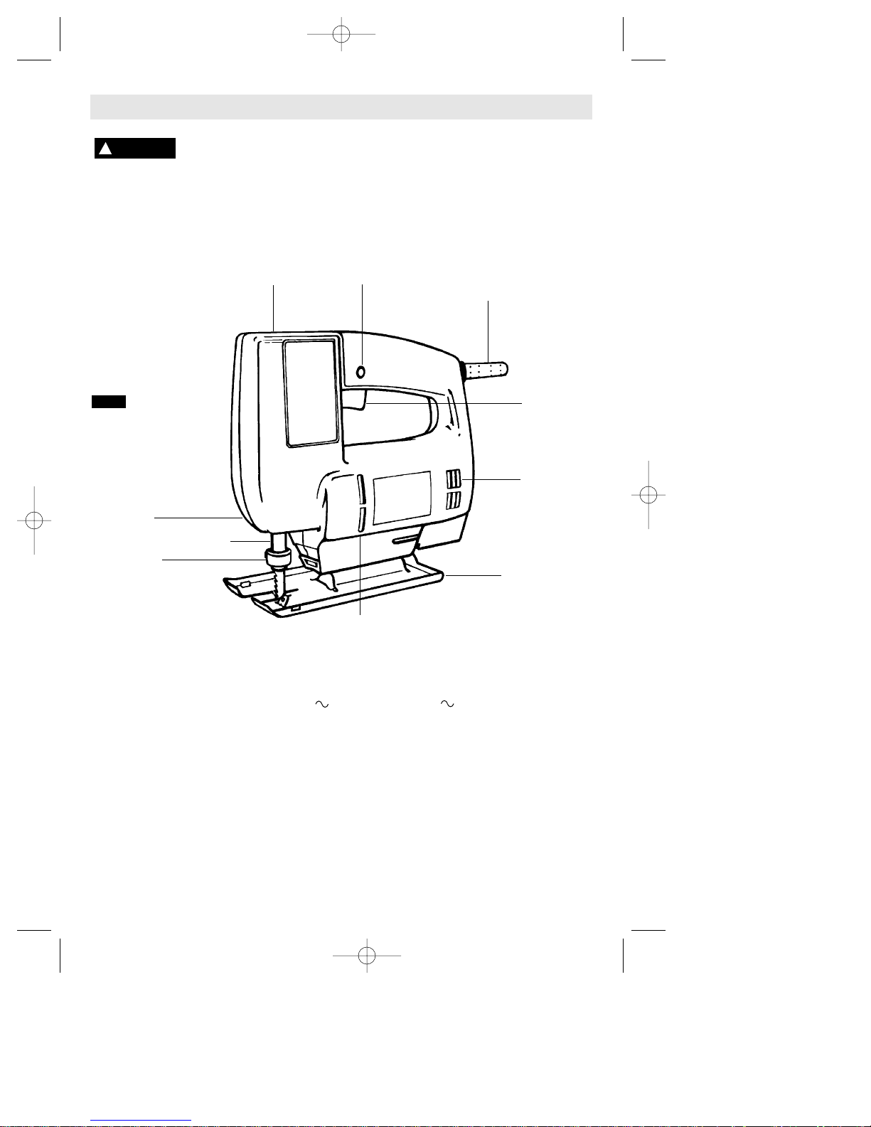
Jigsaws
BLADE
HOLDER
“LOCK-ON”
BUTTON
VENTILATION
OPENINGS
FOOT
VENTILATION
OPENINGS
PLUNGER
TRIGGER
SWITCH
GEAR
HOUSING
TOP OF FRONT
HOUSING
CORD
FIG. 1
Model number 4225 4235
Voltage rating 120 V 50 - 60Hz 120 V 50 - 60Hz
Amperage rating 3.2 A 3.2 A
No load speed n
0
3,200/min n0 0-3,200/min
Blade Action Standard Standard
Stroke Length 16 mm 16 mm
Maximum Capacities
Wood 60 mm 60 mm
Aluminium 6 mm 6 mm
Steel 3 mm 3 mm
1 mm = .039 inches
SM 2610995772 8/00 9/14/00 8:53 AM Page 6
Page 7
-7-
Cutting Tips
Assembly
TRIGGER SWITCH WITH
"LOCK-ON" BUTTON
Your jigsaw can be turned "ON" or "OFF" by
squeezing or releasing the trigger. Your jigsaw
is also equipped with "Lock-ON" button
located just above the trigger that allows
continuous operation without holding the
trigger.
TO LOCK SWITCH ON: Squeeze trigger fully,
depress button and release trigger.
TO UNLOCK THE SWITCH: Squeeze trigger
and release it without depressing the "LockON" button.
If the "Lock-ON" button is
continuously being de-
pressed, the trigger cannot be released.
VARIABLE SPEED CONTROLLED
TRIGGER SWITCH (Model 4235 only)
Your Jigsaw is equipped with a variable
speed trigger switch. The Jigsaw speed can
be controlled from minimum to maximum
nameplate strokes per mimute by the
pressure you apply to the trigger. Apply more
pressure to increase the speed and release
pressure to decrease speed.
!
WARNING
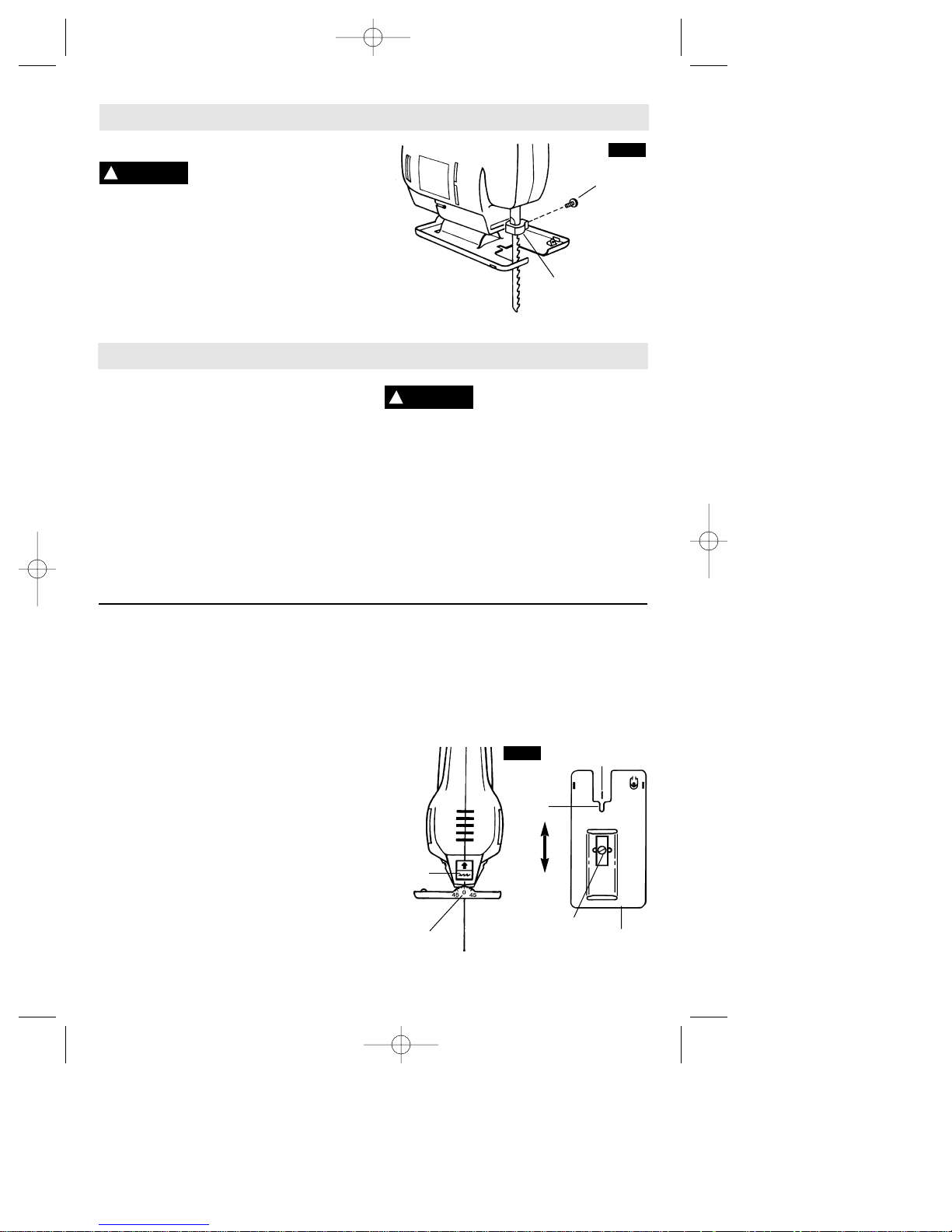
Attaching the Blade
To prevent personal injury,
always disconnect plug from
power source before assembling parts, making
adjustments, or changing blades.
1. Loosen blade screw in the blade holder and
insert blade to full depth with teeth facing in
direction of cut as shown in (Fig. 2).
2. Securely tighten blade screw on the side of
blade holder with a flat tip screwdriver.
BLADE
HOLDER
BLADE
SCREW
!
WARNING
FIG. 2
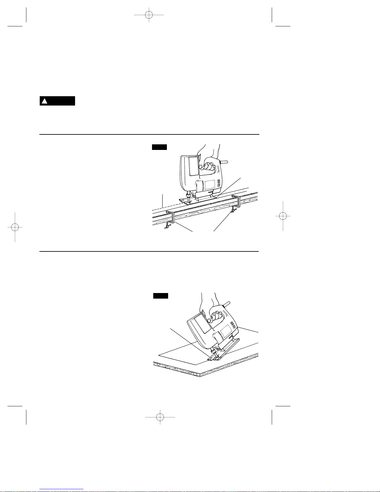
Operating Instructions
Face the good side of the material down and
secure it in a bench vise or clamp it down.
Draw cutting lines or designs on the side of
the material facing up towards you. Then
place the front edge of the saw foot on the
work and line up the blade with the line to be
cut. Hold the jigsaw firmly, turn it on, and
press down (to keep the saw foot flat against
the work) as you slowly push the saw in the
direction of the cut.
Build up cutting rate gradually, cutting close
to the line (unless you want to leave stock for
finish sanding). As you cut you may have to
adjust or relocate the vise or clamps to keep
the work stable. do not force the saw or he
blade teeth may rub and wear without cutting
and the blade may break. Let the saw do
most of the work. When following curves, cut
slowly so the blade can cut through cross
grain. This will give you an accurate cut and
will prevent the blade from wandering.
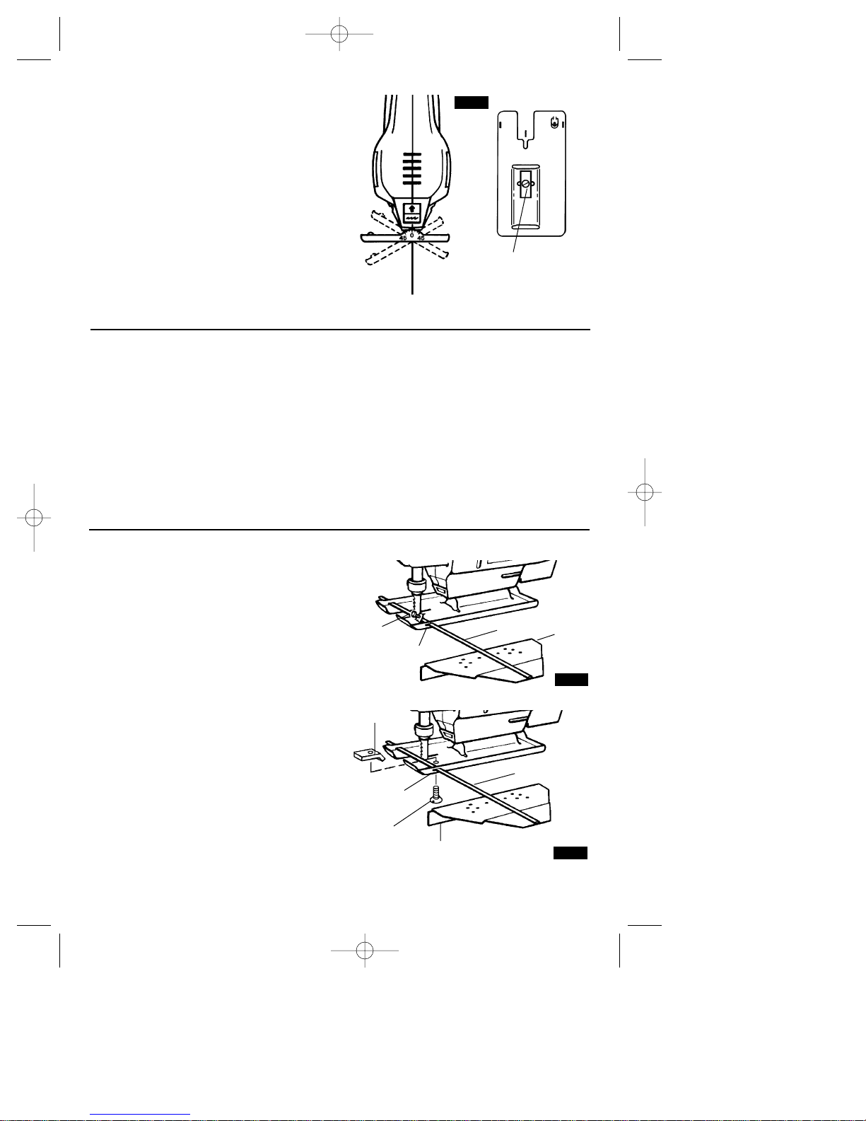
REDUCED-SPLINTER CUTTING
Reduced-splinter cutting is used when
cutting through plywood or a similar material.
The foot must be horizontal 0˚ (Fig. 3), and the
use of a hollow ground or smooth cutting
blade is recommended during reducedsplinter cutting.
FIG. 3
HORIZONTAL
0˚
FOOT
ADJUSTMENT
SCREW
FOOT
SLOT
BLADE
BLADE
STORAGE
SM 2610995772 8/00 9/14/00 8:53 AM Page 7
Page 8
-8-
PLUNGE CUTTING
Plunge cutting is useful and time-saving in
making rough openings in softer materials. It
is not necessary to drill a hole for an inside or
pocket cut. Draw lines for the opening, hold
the saw firmly, tilt it forward so that the toe of
the saw foot rests on the work, but with the
blade well clear of the work. Start the motor,
and then very gradually lower the blade.
When it touches, continue pressing down on
the toe of the saw foot slowly pivoting the
saw like a hinge until the blade cuts through
and the foot rests flat on the work. Then saw
ahead on the line of cut. We do not
recommend plunge cutting with a scroll blade
(Fig. 5).
To make sharp corners, cut up to the corner,
then back up slightly before rounding the
corner. After the opening is complete, go
back to each corner and cut it from the
opposite direction to square it off. Do not try
to plunge cut into hard materials such as
steel.
Always disconnect the plug from power
source before making adjustments. Your saw
has an adjustable foot for doing reduced
splinter cutting. To adjust: loosen the foot
adjustment screw in the bottom of foot with a
flat tip screwdriver, and slide the foot forward
so the slot in foot surrounds the blade on
both sides and securely tighten foot
adjustment screw.
The foot must be moved
backward when using the
bevel adjustment, or any other blade than
hollow or smooth cutting blades.
If finished materials must be cut face up, use
splinter free setting and reverse tooth blade
available at your dealer. Note: Do not use the
blade provided with your jigsaw during
reduced cutting since it is not hollow ground
or smooth cutting blade. These blades can be
purchased from your dealer.
BLADE STORAGE COMPARTMENT
Your saw is equipped with a blade storage
area (Fig. 3) on the backside of your saw. To
open, slide door up in direction of arrow. To
close, slide slide door in opposite direction.
Be sure door is closed to prevent blades from
falling out.
CUTTING WITH A STRAIGHTEDGE
Always use a rough-cut blade when possible.
Clamp a straightedge on the work parallel to
the line of cut and flush with the side of the
saw foot. (Either first mark the line of cut and
then position the straightedge parallel and at
the same distance as between the blade and
the side edge of the foot, or first mark the
side edge of the foot and then clamp the
straightedge on the mark and parallel to the
line of cut Fig. 4)
As you cut, keep the saw foot edge flush
against the straightedge and flat on th work
(Fig. 4).
FIG. 5
TOE
OF
FOOT
FIG. 4
LINE
OF
CUT
FOOT AGAINST
STRAIGHTEDGE
CLAMPS
!
CAUTION
SM 2610995772 8/00 9/14/00 8:53 AM Page 8
Page 9
-9-
BEVEL OR ANGLE CUTTING
Disconnect the cord from the power source.
The foot can be adjusted to cut any angle
from 0˚ to 45˚. TO ADJUST: Loosen the foot
adjustment screw in the bottom of foot with a
flat-tip screwdriver. Position foot to desired
angle and securely tighten screw. After
adjusting foot, make a sample cut to check
the angle (Fig. 6).
FIG. 6
BACK VIEW
BOTTOM VIEW
FOOT
ADJUSTMENT
SCREW
METAL CUTTING
When cutting metal clamp material down. Be
extra certain that you move the saw along
slowly. Use lower speeds. Do not twist, bend,
or force the blade. If the saw jumps or
bounces, use a blade with finer teeth. If the
blade seems clogged when cutting soft
metal, use a blade with coarser teeth.
For easier cutting, lubricate the blade with a
stick of cutting wax, if available, or with
kerosene when cutting aluminum or cutting
oil when cutting steel. Thin metal should be
sandwiched between two pieces of wood or
tightly clamped on a single piece of wood
(wood on top of the metal). Draw the cut lines
or design on the top piece of wood.
When cutting aluminum extrusion or angle
iron, clamp the work in a bench vise and saw
close to the vise jaws.
When sawing tubing and the diameter is
larger than the blade is deep, cut through the
wall of the tubing and then insert the blade
into the cut rotating the tube as you saw.
RIP FENCE AND CIRCLE CUTTING GUIDE
This accessory is available at an extra cost. It
is used for fast and accurate straight and
circle cutting (Fig. 7a & 7b).
ATTACHING RIP FENCE
1. Insert bar of rip fence through the slots
provided in foot, from either side of foot with
the edge guide facing down (Fig. 7a & 7b).
OLD STYLE FOOT
2. Thread the clamp screw through threaded
hole in tab on left side of foot, and securely
tighten clamp screw with a screwdriver
against rip fence bar (Fig. 7a).
NEW STYLE FOOT
2. Thread the clamp screw from bottom side
of foot through the threaded hole and thread
into the clamp on left side of foot, and
securely tighten clamp screw with a
screwdriver, to clamp the rip fence bar in
place (Fig. 7b).
FIG. 7b
EDGE GUIDE
DOWN
BAR
CLAMP
SLOT
CLAMP
SCREW
FIG. 7a
EDGE
GUIDE
DOWN
BAR
CLAMP
SCREW
SLOT
SM 2610995772 8/00 9/14/00 8:53 AM Page 9
Page 10
-10-
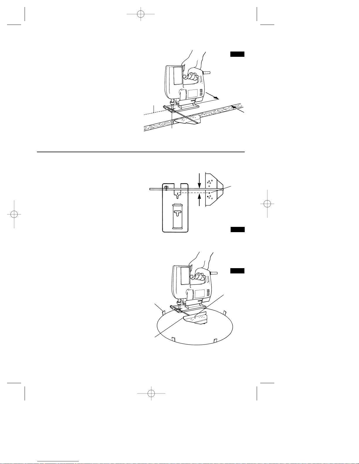
STRAIGHT CUTTING
Once the rip fence is attached, measure from
the edge of work to the line of cut, and set
edge guide of rip fence to the same distance
and then securely tighten clamp screw (Fig. 8).
CIRCLE CUTTING
1. Before attaching the rip fence, draw a
circle and drive a finishing nail in the center of
circle.
2. Drill or plunge cut near the circles edge,
turn saw off and disconnect the plug from
power source (Fig. 10).
3. Attach rip fence to saw with the edge guide
facing UP. In order for the rip fence to cut a
circle, the nail must be in alignment with the
blade, as shown in (Fig. 9).
4. Measure the distance from the selected
hole to the blade to be equal to the circle
radius.
5. Insert plug into power source, hold the saw
firmly, squeeze trigger and slowly push the
saw forward. To make a hole, cut from inside
the circle; To make wheels or discs, cut from
the outside.
Cutting Tip: Cut slowly so the blade will stay
straight in the cut. Place small wedges in the
cut as shown in Fig. 10, to keep the inner
circle from spreading when near the end of
the cut.
FIG. 9
FRONT EDGE OF BLADE MUST
BE IN ALIGNMENT WITH NAIL
NAIL
DESIRED
WIDTH
LINE OF
CUT
CLAMP
SCREW
FIG. 8
WEDGE
FINISHING
NAIL
EDGE
GUIDE
UP
FIG. 10
SM 2610995772 8/00 9/14/00 8:54 AM Page 10
Page 11

-11-
Service
Preventive maintenance
performed by unauthorized personnel may result in misplacing
of internal wires and components which
could cause serious hazard. We
recommend that all tool service be
performed by a Skil Factory Service Center
or Authorized Skil Service Station.
TOOL LUBRICATION
Your Skil tool has been properly lubricated
and is ready to use. It is recommended that
tools with gears be regreased with a special
gear lubricant at every brush change.
CARBON BRUSHES
The brushes and commutator in your tool
have been engineered for many hours of
dependable service. To maintain peak
efficiency of the motor, we recommend
every two to six months the brushes be
examined. Only genuine Skil replacement
brushes specially designed for your tool
should be used.
BEARINGS
After about 300-400 hours of operation, or at
every second brush change, the bearings
should be replaced at Skil Factory Service
Center or Authorized Skil Service Station.
Bearings which become noisy (due to heavy
load or very abrasive material cutting) should
be replaced at once to avoid overheating or
motor failure.
Cleaning
To avoid accidents always
disconnect the tool from
the power supply before cleaning or
performing any maintenance. The tool may
be cleaned most effectively with
compressed dry air. Always wear safety
goggles when cleaning tools with
compressed air.
Ventilation openings and switch levers must
be kept clean and free of foreign matter. Do
not attempt to clean by inserting pointed
objects through openings.
Certain cleaning agents
and solvents damage
plastic parts. Some of these are: gasoline,
carbon tetrachloride, chlorinated cleaning
solvents, ammonia and household
detergents that contain ammonia.
!
WARNING
!
WARNING
Maintenance
!
CAUTION
Accessories
If an extension cord is
necessary, a cord with
adequate size conductors that is capable
of carrying the current necessary for your
tool must be used. This will prevent
excessive voltage drop, loss of power or
overheating. Grounded tools must use 3wire extension cords that have 3-prong
plugs and receptacles.
NOTE: The smaller the gauge number, the
heavier the cord.
RECOMMENDED SIZES OF EXTENSION CORDS
120 VOLT ALTERNATING CURRENT TOOLS
!
WARNING
Tool’s
Ampere
Rating
Cord Size in A.W.G.
Wire Sizes in mm
2
3-6
6-8
8-10
10-12
12-16
18 16 16 14 .75 .75 1.5 2.5
18 16 14 12 .75 1.0 2.5 4.0
18 16 14 12 .75 1.0 2.5 4.0
16 16 14 12 1.0 2.5 4.0 —
14 12 — — — — — —
25 50 100 150 15 30 60 120
Cord Length in Feet Cord Length in Meters
SM 2610995772 8/00 9/14/00 8:54 AM Page 11
Page 12

-12-
Vous devez lire et comprendre toutes les instructions. Lenon-respect, même
partiel, des instructions ci-après entraîne un risque de choc életrique, d'incendie
et/ou de blessures graves.
CONSERVEZ CES INSTRUCTIONS
Règles de Sécurité Générales
AVERTISSEMENT
!
Aire de travail
Veillez à ce que l'aire de travail soit propre et bien
éclairée. Le désordre et le manque de lumière
favorisent les accidents.
N'utilisez pas d'outils électriques dans une
atmosphère explosive, par exemple enprésence de
liquides, de gaz ou de poussières inflammables. Les
outils électriques créent des étincelles qui pourraient
enflammer les poussières ou les vapeurs.
Tenez à distance les curieux, les enfants et les
visiteurs pendant que vous travaillezavec un outil
électrique. Ils pourraient vous distraire et vous faire
faire une fausse manoeuvre.
Sécurité électrique
Les outils à double isolation sont équipés d'une fiche
polarisée (une des lames est pluslarge que l'autre),
qui ne peut se brancher que d'une seule façon dans
une prise polarisée. Si la fiche n'entre pas
parfaitement dans la prise, inversez sa position ; si
elle n'entre toujours pasbien, demandez à un
électricien qualifié d'installer une prise de courant
polarisée. Ne modifiez pas la fiche de l'outil. La
double isolation élimine le besoin d'un cordon
d'alimentationà trois fils avec mise à la terre ainsi que
d'une prise de courant mise à la terre.Avant de brancher
l'outil, assurez-vous que la tension de la prise
correspond, à celle indiquée sur la plaque signalétique.
N'utilisez pas d'outils prévus pour courant alternatif
seulement avec une source de courant continu.
Évitez tout contact corporel avec des surfaces mises à
la terre (tuyauterie, radiateurs, cuisinières,
réfrigérateurs, etc.). Le risque de choc électrique est
plus grand si votre corps est encontact avec la terre.Si
l'utilisation de l'outil électrique dans un endroit humide
est inévitable, un disjoncteur de fuite à la terre doit être
utilisé pour alimenter votre outil. Des chaussures et des
gants en caoutchouc d'électricien contribueront à
accroître davantage votre sécurité personnelle.
N'exposez pas les outils électriques à la pluie ou à
l'eau. La présence d'eau dans un outil électrique
augmente le risque de choc électrique.
Ne maltraitez pas le cordon. Ne transportez pas l'outil
par son cordon et ne débranchez pas la fiche en tirant
sur le cordon. N'exposez pas le cordon à la chaleur, à
des huiles, à des arêtes vives ou à des pièces en
mouvement. Remplacez immédiatement un cordon
endommagé. Un cordon endommagé augmente le
risque de choc électrique.
Lorsque vous utilisez un outil électrique à l'extérieur,
employez un prolongateur pour l'extérieur marqué «
W-A » ou « W ». Ces cordons sont faits pour être
utilisés à l'extérieur et réduisent le risque de choc
électrique. Reportez-vous aux « Dimensions
recommandées des cordons de rallonge » dans la
section Accessoires de ce manuel.
Sécurité des personnes
Restez alerte, concentrez-vous sur votre travail et
faites preuve de jugement. N'utilisez pas un outil
électrique si vous êtes fatigué ou sous l'influence de
drogues, d'alcool ou de médicaments. Un instant
d'inattention suffit pour entraîner des blessures graves.
Habillez-vous convenablement. Ne portez ni
vêtements flottants ni bijoux. Confinez les cheveux
longs. N'approchez jamais les cheveux, les
vêtements ou les gants des pièces en mouvement.
Des vêtements flottants, des bijoux ou des cheveux
longs risquent d'être happés par des pièces en
mouvement. Gardez les poignées sèches, propres et
exemptes d'huile et de graisse.
Méfiez-vous d'un démarrage accidentel. Avant de
brancher l'outil, assurez-vous que son interrupteur
est sur ARRÈT. Le fait de transporter un outil avec le
doigt sur la détente ou de brancher un outil dont
l'interrupteur est en position MARCHE peut mener tout
droit à un accident.
Enlevez les clés de réglage ou de serrage avant de
démarrer l'outil. Une clé laissée dans une pièce
tournante de l'outil peut provoquer des blessures.
Ne vous penchez pas trop en avant. Maintenez un bon
appui et restez en équilibre entout temps. Un bonne
stabilité vous permet de mieux réagir à une situation
inattendue.
Utilisez des accessoires de sécurité. Portez toujours
des lunettes ou une visière. Selon les conditions,
portez aussi un masque antipoussière, des bottes de
sécurité antidérapantes, un casque protecteur et/ou un
appareil antibruit.
Utilisation et entretien des outils
Immobilisez le matériau sur une surface stable au
moyen de brides ou de toute autre façon adéquate. Le
fait de tenir la pièce avec la main ou contre votre corps
offre une stabilité insuffisante et peut amener un
dérapage de l'outil.
Ne forcez pas l'outil. Utilisez l'outil approprié à la
tâche. L'outil correct fonctionne mieux et de façon plus
SM 2610995772 8/00 9/14/00 8:54 AM Page 12
Page 13

-13-
Tenez l'outil par les surfaces isolées de préhension
en exécutant une opération au cours de laquelle
l'outil de coupe peut venir en contact avec les fils
cachés ou son propre cordon. Le contact avec un fil
sous tension rendra les pièces métalliques exposées
de l'outil sous tension et causera des chocs à
l'opérateur. Ne percez, fixez et ne rentrez pas dans
des murs existants ou autres endroits aveugles
pouvant abriter des fils électriques. Si cette situation
est inévitable, débranchez tous les fusibles ou les
disjoncteurs alimentant ce site.
Ne tenez jamais la gâchette bloquée en position de
marche. Avant de brancher l'outil, assurez-vous
que le blocage de la gâchette est inhibé. Les mises
en marche accidentelles peuvent causer des
blessures.
Soyez au courant de l'emplacement et de la
position du bouton de blocage en marche de la
gâchette. Si l'interrupteur est bloqué en marche
durant l'usage, soyez prêt, dans des cas d'urgence, à
le mettre à l'arrêt en appuyant d'abord sur la
gâchette, puis en la relâchant immédiatement sans
appuyer sur le bouton de blocage en marche.
Gardez les mains à l'écart de la zone de coupe. Ne
placez surtout pas la main sous le matériau que
vous coupez. Il est impossible de déterminer
exactement la proximité de la lame de votre main.
Évitez de vous placer les mains entre le carter
d'engrenages et le porte-lame de la scie. Le porte-
lame à mouvement alternatif risquerait de vous pincer
les doigts.
N'utilisez pas de lames émoussées ou
endommagées. Les lames pliées peuvent aisément
se fracturer ou causer un rebond.
Avant de commencer à couper, mettez l'outil en
marche et attendez que la lame atteigne sa vitesse
maximale. L'outil peut trembler ou vibrer si la vitesse
de la lame est trop lente au début de la coupe, et il
peut éventuellement rebondir.
Portez toujours des lunettes à coques latérales ou
des lunettes de protection en utilisant cet outil.
Utilisez un respirateur ou un masque antipoussières pour les applications produisant de la
poussière.
Il importe de bien assujettir la pièce sur laquelle
vous travaillez. Ne la tenez jamais dans votre main
ou sur vos jambes. Les pièces minces et plus petites
sécuritaire. Respectez aussi la vitesse de travail qui lui
est propre.
N'utilisez pas un outil si son interrupteur est bloqué.
Un outil que vous ne pouvez pas commander par son
interrupteur est dangereux et doit être réparé.
Débranchez la fiche de l'outil avant d'effectuer un
réglage, de changer d'accessoire oude ranger l'outil.
De telles mesures préventives de sécurité réduisent le
risque de démarrage accidentel de l'outil.
Rangez les outils hors de la portée des enfants et
d'autres personnes inexpérimentées. Les outils sont
dangereux dans les mains d'utilisateurs novices.
Prenez soin de bien entretenir les outils. Les outils de
coupe doivent être toujours bien affûtés et propres.
Des outils bien entretenus, dont les arêtes sont bien
tranchantes, sont moins susceptibles de coincer et plus
faciles à diriger.Toute altération ou modification
constitue un usage erroné et peut causer un danger.
Soyez attentif à tout désalignement ou coincement
des pièces en mouvement, à tout bris ou à toute autre
condition préjudiciable au bon fonctionnement de
l'outil. Si vous constatez qu'un outil est endommagé,
faites-le réparer avant de vous en servir. De
nombreux accidents sont causés par des outils en
mauvais état. Élaborez un calendrier d'entretien
périodique de votre outil.
N'utilisez que des accessoires que le fabricant
recommande pour votre modèle d'outil. Certains
accessoires peuvent convenir à un outil, mais être
dangereux avec un autre.
Réparation
La réparation des outils électriques doit être confiée à
un réparateur qualifié. L'entretien ou la réparation d'un
outil électrique par un amateur peut avoir des
conséquences graves. Ainsi, des fils internes peuvent
être mal placés ou pincés, des ressorts de rappel de
protecteur peuvent être montés erronément.
Pour la réparation d'un outil, n'employez que des
pièces de rechange d'origine. Suivez les directives
données à la section « Réparation » de ce manuel.
L'emploi de pièces non autorisées ou le non-respect
des instructions d'entretien peut créer un risque de
choc électrique ou de blessures. Certains agents
nettoyants tels qu'essence, tétrachlorure de carbone,
ammoniac, etc., peuvent abîmer les pièces en plastique.
Règles de sécurité concernant les scies sauteuses
SM 2610995772 8/00 9/14/00 8:54 AM Page 13
Page 14

-14-
peuvent fléchir ou vibrer avec la lame, risquant ainsi
de vous faire perdre le contrôle.
Avant de commencer à scier, assurez-vous que
toutes les vis de réglage et que le porte-lame sont
serrés. Les vis de réglage et porte-lame lâches
peuvent faire glisser l'outil ou la lame et ainsi vous
faire perdre le contrôle.
En retirant la lame de l'outil, évitez le contact avec
la peau et utilisez des gants protecteurs appropriés
en saisissant la lame ou l'accessoire. Les
accessoires peuvent être chauds après un usage
prolongé.
Si votre outil est muni d’un sac à poussière, videz-le
fréquemment et après chaque opération de sciage.
Une autocombustion peut se déclencher en réaction au
mélange de l’huile ou de l’eau et des particules de
poussière. La mise au rebut des poussières doit être
extrêmement bien supervisée, les matériaux sous forme
de particules fines pouvant être explosifs. Ne pas mettre
le contenu en contact direct avec le feu.
Les travaux à la machine
tel que ponçage, sciage,
meulage, perçage et autres travaux du bâtiment
peuvent créer des poussières contenant des produits
chimiques qui sont des causes reconnues de cancer,
de malformation congénitale ou d’autres problèmes
reproductifs. Ces produits chimiques sont, par
exemple :
• Le plomb provenant des peintures à base de plomb,
• Les cristaux de silices provenant des briques et du
ciment et d’autres produits de maçonnerie, et
• L’arsenic et le chrome provenant des bois traités
chimiquement
Le niveau de risque dû à cette exposition varie avec la
fréquence de ces types de travaux. Pour réduire
l’exposition à ces produits chimiques, il faut travailler
dans un lieu bien ventilé et porter un équipement de
sécurité approprié tel que certains masques à poussière
conçus spécialement pour filtrer les particules
microscopiques.
AVERTISSEMENT
!
SM 2610995772 8/00 9/14/00 8:54 AM Page 14
Page 15

-15-
Symboles
Important : Certains des symboles suivants peuvent être utilisés sur votre outil. Veuillez les étudier et apprendre
leur signification. Une interprétation appropriée de ces symboles vous permettra d'utiliser l'outil de façon plus
efficace et plus sûre.
Symbole Nom Désignation/Explication
V Volts Tension (potentielle)
A Ampères Courant
Hz Hertz Fréquence (cycles par seconde)
W Watt Puissance
kg Kilogrammes Poids
min Minutes Temps
s Secondes Temps
Diamètre Taille des mèches de perceuse, meules,
etc.
n
0
Vitesse à vide Vitesse de rotation, à vide
.../min Tours ou mouvement alternatif par Tours, coups, vitesse en surface, orbites,
minute etc., par minute,
0 Position d'arrêt Vitesse zéro, couple zéro ...
1, 2, 3, ... Réglages du sélecteur Réglages de vitesse, de couple ou de
l, ll, lll, ... position. Un nombre plus élevé signifie
une vitesse plus grande.
Sélecteur variable à l'infini avec arrêt La vitesse augmente depuis le réglage 0
Flèche Action dans la direction de la flèche
Courant alternatif Type ou caractéristique du courant
Courant continu Type ou caractéristique du courant
Courant alternatif Type ou caractéristique du courant
ou continu
Construction classe II Désigne des outils construits avec double
isolation
Borne de terre borne de mise à la terre
Symbole d'avertissement Alerte l'utilisateur aux messages
d'avertissement.
Sceau Ni-Cad RBRCmc Désigne le programme de recyclage des piles
Ni-Cad.
Ce symbole signifie que cet
outil est approuvé par
Underwriters Laboratories.
Ce symbole signifie que cet
outil est approuvé par
l'Association canadienne de
normalisation.
Ce symbole signifie que
cet outil est approuvé
conformément aux normes
canadiennes par Underwriters
Laboratories.
Ce symbole
signifie que
cet outil se
conforme aux
normes
mexicaines
NOM.
Ce symbole signifie que cet outil
est approuvé par Underwriters
Laboratories et qu’il a été
homologué selon les normes
canadiennes par Underwriters
Laboratories.
SM 2610995772 8/00 9/14/00 8:54 AM Page 15
0
Page 16

-16-
Description fonctionnelle et spécifications
Débranchez la fiche de la prise de courant avant d'effectuer quelque assemblage
ou réglage que ce soit ou de changer les accessoires. Ces mesures de sécurité
préventive réduisent le risque d'une mise en marche accidentelle de l'outil.
AVERTISSEMENT
!
PORTE-LAME
BOUTON DE
BLOCAGE EN
MARCHE
PRISES
D’AIR
SEMELLE
PRISES
D’AIR
PISTON
GÂCHETTE DE
COMMANDE
CARTER
D’ENGRENAGES
DESSUS DUCARTER
AVANT
CORDON
FIG. 1
Sierras caladoras
Numéro de modèle 4225 4235
Tension nominale 120 V 50 - 60Hz 120 V 50 - 60Hz
Intensité nominale 3,2 A 3,2 A
Vitesse à vide n0 3,200/min n0 0-3,200/min
Action de la lame Standard Standard
Longueur de la course 16 mm 16 mm
Capacites maximales
Bois 60 mm 60 mm
Aluminium 6 mm 6 mm
Acier 3 mm 3 mm
1 mm = 0,039 po.
SM 2610995772 8/00 9/14/00 8:54 AM Page 16
Page 17

-17-
Conseils Pratiques
Assemblage
GÂCHETTE DE COMMANDE AVEC
BOUTON DE BLOCAGE EN MARCHE
Votre scie sauteuse peut être mise en marche ou au
repos à l’enfoncement ou au relâchement de la
gâchette.Elle est aussi équipée, juste au-dessus de la
gâchette, d’un bouton de blocage en marche qui
maintient l’interrupteur sous tension sans que vous ayez
à appuyer sur la gâchette de commande.
BLOCAGE DE L'INTERRUPTEUR EN MARCHE :
Appuyez à fond sur la gâchette, enfoncez le bouton et
relâchez la gâchette.
DÉBLOCAGE DE L’INTERRUPTEUR : appuyez sur la
gâchette et relâchez-la sans toucher au bouton de
blocage en marche.
Le relâchement de la
gâchette est impossible si le
bouton de blocage en marche est maintenu enfoncé.
GÂCHETTE DE COMMANDE À VITESSE VARIABLE
(Modèle 4235 seulement)
Votre scie sauteuse est équipée d’une gâchette de
commande à vitesse variable. Selon la pression que
vous exercez sur la gâchette, vous êtes en mesure de
choisir le nombre de courses compris entre les valeurs
minimale et maximale spécifiées sur la plaquette
emblématique.
Pose de la lame
Pour éviter le risque de bles-
sure, débranchez toujours le
cordon de la source d’alimentation avant d’effectuer les
réparations et réglages ou de remplacer les lames.
1. Desserrez la vis de fixation de la lame (sur le portelame) et insérez la lame à fond, ses dents orientées dans
le sens de coupe comme l’indique la fig. 2.
2. Serrez solidement la vis de la lame sur le côté du
porte-lame à l'aide d'un tournevis à extrémité plate.
Consignes de fonctionnement
AVERTISSEMENT
!
AVERTISSEMENT
!
PORTE-LAME
VIS DE
FIXATION DE
LA LAME
FIG. 3
Tournez le matériau à l’envers en prenant soin de
l’assujettir dans un étau ou avec des serres. Tracez les
lignes ou les dessins à découper sur le côté qui vous fait
face. Placez le bord avant de la semelle de la scie sur la
pièce et alignez la lame avec la ligne à découper. Tenez la
scie d’une main ferme, mettez-la en marche et en
appuyant (pour maintenir la semelle à plat sur la pièce)
poussez-la lentement dans le sens de la coupe.
Accélérez graduellement en sciant près de la ligne (à
moins que vous préfériez enlever l’excédent à la
ponceuse). Il est possible, à un certain point, que vous
ayez à régler l’étau ou les serres pour assurer la stabilité
de la pièce. Ne forcez surtout pas la scie car ses dents
peuvent frotter et s’user sans couper risquant de
fracturer la lame. Laissez travailler la scie. Dans les
courbes, ralentissez pour permettre à la lame de couper
à travers les fibres. Vous obtiendrez ainsi une coupe
exacte et éviterez que la lame dévie.
SCIAGE À ÉCLATS RÉDUITS
Le sciage à éclats réduits sert à tailler le contreplaqué
ou un matériau semblable. Dans ce cas, la semelle de
la scie doit être parfaitement à l'horizontale, c'est-àdire 0° (Fig. 3), et l'emploi d'une lame évidée ou de
finition est recommandé.
FIG. 3
HORIZONTALE
0°
VIS DE
RÉGLAGE DE
LA SEMELLE
SEMELLE
FENTE
LAME
RANGEMENT
DES LAMES
SM 2610995772 8/00 9/14/00 8:54 AM Page 17
Page 18

-18-
Débranchez toujours le cordon électrique de la source
d'alimentation avant de procéder aux réglages. La
semelle de votre scie est réglable à cette fin. Pour la
régler : Au moyen d'un tournevis à extrémité plate,
desserrez la vis de réglage de la semelle située audessous de la semelle. Glissez ensuite la semelle vers
l'avant de sorte que la fente de la semelle entoure la
lame des deux côtés et resserrez fermement la vis de
réglage de la semelle.
Lors de l’utilisation du réglage
pour coupe en biseau ou de lames
autres que celles de type évidé ou de coupe lisse, la
semelle doit être déplacée vers l'arrière.
Si le matériau fini doit être scié à l'endroit, choisissez
le sciage sans éclats et une lame à denture inversée
que vous pouvez vous procurer chez le revendeur.
Remarque : N'utilisez pas la lame fournie avec votre
scie sauteuse pour le sciage à éclats réduits
puisqu'elle n'est pas du type évidé ni de coupe lisse.
Vous pouvez vous procurer ces lames chez votre
revendeur habituel.
COMPARTIMENT DE RANGEMENT DE LAME
Votre scie dotée d’un cpmpartiment servant à ranger
les lames (fig. 3). Pour l’ouvrir, glissez son couvercle
dans le sens indiqué par la flèche. Pour le refermer,
glissez-le dans le sens opposé. Assurez-vous que le
couvercle est fermé pour éviter que les lames ne
sortent.
SCIAGE AVEC GUIDE DE COUPE
Utilisez toujours une lame de coupe grossière, si
possible. Fixez un guide à la pièce, parallèle à la ligne de
coupe et au ras du côté de la semelle de la scie. (Soit
que vous traciez la ligne de coupe, puis placiez le guide
parallèle à la distance entre la lame et le côté de la
semelle ou que vous fassiez une marque au ras la
semelle, puis fixiez le guide sur la marque, parallèle à la
ligne de coupe fig. 4).
Sur les modèles à chantournage automatique, il est
recommandé de déverrouiller le pommeau de
chantournage et de couper avec la lame à la position
ARRIÈRE du porte-lame. En sciant, maintenez le côté
de la semelle de la scie bien appuyé contre le guide et à
plat sur la pièce (fig. 4).
COUPE EN PLONGÉE
La coupe en plongée est utile et pratique pour pratiquer
des ouvertures grossières dans les matériaux plus
mous. Il n’est pas nécessaire de percer un trou pour une
coupe intérieure ou en guichet. Tracez les lignes de
l’ouverture, tenez fermement la scie, inclinez-la de sorte
que l’extrémité avant de sa semelle repose sur la pièce,
mais la lame suffisamment éloignée. Mettez le moteur en
marche, puis abaissez très graduellement la lame. Quand
elle touche à la pièce, continuez d’appuyer sur l’extrémité
avant de la semelle en rabattant lentement la scie comme
une charnière jusqu’à ce que la lame traverse le matériau
et que la semelle repose à plat sur la pièce. Ensuite,
continuez de scier dans la ligne. Nous ne
recommandons pas la coupe en plongée avec une lame
à chantourner (fig. 5).
Pour exécuter des coins bien carrés, coupez jusqu’au
coin, puis reculez légèrement avant de contourner.
N'essayez pas de pratiquer la coupe en plongée dans
des matériaux durs tels que l'acier.
FIG. 5
EXTRÉMITÉ
AVANT DE
LA SEMELLE
FIG. 4
LIGNE DE
COUPE
SEMELLE
APPUYÉE
CONTRE GUIDE
SERRE-JOINTS
ATTENTION
!
SM 2610995772 8/00 9/14/00 8:54 AM Page 18
Page 19

-19-
COUPE BISEAUTÉE OU OBLIQUE
Débranchez de la prise de courant le cordon
d’alimentation. La semelle peut être inclinée pour scier à
tout angle compris entre 0 et 45°. POUR LA RÉGLER :
Au moyen d'un tournevis à extrémité plate, desserrez
la vis de réglage de la semelle située au-dessous de la
semelle. Inclinez la semelle à l'angle désiré et
resserrez fermement la vis. Suivant le réglage de la
semelle, exécutez une coupe d'essai dans une retaille
pour vérifier l'angle (Fig. 6).
COUPE DANS LES MÉTAUX
Prenez bien soin d’assujettir le matériau avec des serres.
De même, déplacez la scie lentement. Choisissez les
vitesses lentes. Évitez de tordre, plier ou forcer la lame.
Si la scie saute ou rebondit, utilisez une lame dont les
dents sont plus fines. Si la lame semble s’empâter dans
le métal doux, utilisez-en une à dents plus grosses.
Traitez la lame à la cire de coupe, si disponible, ou au
kérosène pour faciliter le sciage dans l’aluminium, ou à
l’huile de coupe dans l’acier. Le métal mince devrait être
placé entre deux pièces de bois ou fermement assujetti
de bois (bois par-dessus le métal). Tracez le dessin ou la
ligne de coupe sur la pièce de bois supérieure.
Pour le sciage d’extrusion d’aluminium ou de fer angle,
assujettissez la pièce dans un étau et sciez près des
mâchoires.
Pour le sciage dans les tuyaux de diamètre plus grand
que la profondeur de la lame, taillez à travers la paroi du
tuyau, puis insérez la lame dans le trait de scie et tournez
graduellement le tuyau en sciant.
GUIDE DE REFENTE ET DE COUPE CIRCULAIRE
Cet accessoire est disponible moyennant supplément de
prix. Il permet d’exécuter des coupes rectilignes et
circulaires précises en rapidité (fig. 7a et 7b).
ASSEMBLAGE DU GUIDE DE REFENTE
1. Insérez la barre du guide de refente dans les fentes
prévues à cet effet dans les côtés de la semelle, le guide
de bord orienté vers le BAS (fig. 7a et 7b).
VIEUX SEMELLE DE MODÈLE
2. Introduisez la vis de serrage dans le trou fileté de la
languette (côté gauche de la semelle) et serrez
fermement la vis de serrage à l'aide d'un tournevis
contre la barre du guide de refente (fig. 7a).
NOUVEAU SEMELLE DE MODÈLE
2. Introduisez la vis de serrage depuis le dessous de
la semelle à travers le trou fileté dans le serre-joint sur
le côté gauche de la semelle, et serrez fermement la
vis de serrage à l'aide d'un tournevis, pour bloquer la
barre du guide de refente en place (fig. 7b).
FIG. 6
VUE DE DESSOUS
VIS DE
RÉGLAGE DE
LA SEMELLE
VUE DE DOS
FIG. 7b
PIED DE BORD
INVERSÉ
BARRE
SERRE-
JOINT
FENTE
VIS DE
SERRAGE
FIG. 7a
PIED DE
BORD
INVERSÉ
BARRE
VIS DE
SERRAGE
FENTE
SM 2610995772 8/00 9/14/00 8:54 AM Page 19
Page 20

-20-
COUPE RECTILIGNE
Quand le guide de refente est en place, mesurez la
distance entre le bord de la pièce et la ligne de coupe et
réglez le guide à la même largeur et serrez fermement la
vis (fig. 8).
COUPE CIRCULAIRE
1. Avant d’attacher le guide de refente, tracez un cercle et
enfoncez un clou de finition en son centre.
2. Percez un trou ou faites une coupe en plongée près
du bord du cercle, mettez la scie hors tension et
retirez le cordon de la prise de courant (Fig. 10).
3. Fixez le guide de refente à la scie, le guide de bord
orienté vers le HAUT. Pour que le guide puisse
exécuter une coupe circulaire, il faut que le clou soit
en ligne avec la lame, comme illustré à la Fig. 9.
4. Mesurez la distance depuis le trou choisi jusqu'à la
lame pour correspondre au rayon du cercle.
5. Rebranchez le cordon d’alimentation, saisissez
fermement la scie par la poignée, appuyez sur la
gâchette de commande et dirigez lentement la scie vers
l’avant. Pour découper une ouverture, procédez de
l’intérieur du cercle ; pour découper des roues ou des
disques, procédez de l’extérieur du cercle.
Conseil pratique : Procédez lentement de sorte que la
lame reste bien droite dans le trait de coupe. Insérez des
petits coins de bois dans le trait de coupe (comme l’indi
la fig. 10), pour empêcher le disque intérieur de se
décen-trer quand vous serez sur le point de terminer la
coupe.
LARGEUR
DÉSIRÉE
LIGNE
DE
COUPE
VIS DE
SERRAGE
FIG. 8
FIG. 9
LA LAME DOIT ÊTRE EN LIGNE
AVEC LE CLOU.
CLOU
COIN
CLOU DE
FINITION
EGUIDE DE
BORD VERS LE
HAUT
FIG. 10
SM 2610995772 8/00 9/14/00 8:54 AM Page 20
Page 21

-21-
Entretien
L’entretien préventif
effectué par des employés
non autorisés peut entraîner un positionnement
erroné des composants et des fils internes, et ainsi
causer des dangers sévères. Il est recommandé que
l’entretien et la réparation de nos outils soient confiés
à un centre de service-usine Skil ou à un centre de
service après-vente Skil agréé.
GRAISSAGE DE L’OUTIL
Votre outil Skil a été convenablement graissé et est
prêt à utiliser. Il est recommandé que les outils à
engrenages soient regraissés avec une graisse
spéciale à l’occasion de tout remplacement de balais.
BALAIS DE CHARBON
Les balais et le collecteur de votre outil ont été
conçus pour donner plusieurs heures de
fonctionnement sans aléas. Pour maintenir le moteur
en forme, nous recommandons d’examiner les balais
tous les deux à six mois. Vous ne devriez utiliser que
les balais de rechange d’origine Skil qui conviennent
spécialement à votre outil.
ROULEMENTS
Après environ 300 à 400 heures d’utilisation, ou à
tous les deux remplacements des balais, il faudrait
confier le remplacement des roulements à un centre
de service-usine Skil ou à un centre de service aprèsvente Skil agréé. Les roulements qui sont devenus
bruyants (à cause de sciage de matériaux très
abrasifs ou de durs efforts) devraient être remplacés
à l’instant pour éviter la surchauffe et la défaillance du
moteur.
Nettoyage
Pour éviter le risque
d’accidents, débranchez
toujours l’outil de la prise de courant avant de
procéder au nettoyage ou à l’entretien. Vous pouvez
très bien le nettoyer à l’air comprimé. Dans ce cas,
portez toujours des lunettes de sécurité.
Gardez les prises d’air et les interrupteurs propres et
libres de débris. N’essayez pas de les nettoyer en
introduisant des objets pointus dans leurs ouvertures.
Certains produits de
nettoyage et dissolvants
dont la gazoline, le tétrachlorure de carbone, les
nettoyeurs chlorés, l’ammoniaque et les détergents
ménagers contenant de l’ammoniaque peuvent
abîmer les pièces en plastique.
Maintenance
AVERTISSEMENT
!
AVERTISSEMENT
!
AVERTISSEMENT
!
Accessoires
Si un cordon de rallonge
s'avère nécessaire, vous
devez utiliser un cordon avec conducteurs de
dimension adéquate pouvant porter le courant
nécessaire à votre outil. Ceci préviendra une chute
excessive de tension, une perte de courant ou une
surchauffe. Les outils mis à la terre doivent utiliser des
cordons de rallonge trifilaires pourvus de fiches à trois
broches ainsi que des prises à trois broches.
REMARQUE : Plus le calibre est petit, plus le fil est gros.
DIMENSIONS DE RALLONGES RECOMMANDÉES
OUTILS 120 VOLTS COURANT ALTERNATIF
AVERTISSEMENT
!
Intensité
nominale
de l’outil
Longueur en pieds
Longueur en mètres
3-6
6-8
8-10
10-12
12-16
18 16 16 14 .75 .75 1.5 2.5
18 16 14 12 .75 1.0 2.5 4.0
18 16 14 12 .75 1.0 2.5 4.0
16 16 14 12 1.0 2.5 4.0 —
14 12 — — — — — —
25 50 100 150 15 30 60 120
Calibre A.W.G.
Calibre en mm
2
SM 2610995772 8/00 9/14/00 8:54 AM Page 21
Page 22

-22-
Lea y entienda todas las instrucciones. El incumplimiento de todas las instrucciones
indicadas a continuación puede dar lugar a sacudidas eléctricas, incendios y/o lesiones
personales graves.
CONSERVE ESTAS INSTRUCCIONES
Normas de seguridad para herramientas mecánicas
ADVERTENCIA
!
Area de trabajo
Mantenga el área de trabajo limpia y bien iluminada.
Las mesas desordenadas y las áreas oscuras invitan a
que se produzcan accidentes.
No utilice herramientas mecánicas en atmósferas
explosivas, tales como las existentes en presencia de
líquidos, gases o polvos inflamables. Las
herramientas mecánicas generan chispas y éstas
pueden dar lugar a la ignición del polvo o los vapores.
Mantenga a las personas que se encuentren
presentes, a los niños y a los visitantes alejados al
utilizar una herramienta mecánica. Las distracciones
pueden hacer que usted pierda el control.
Seguridad eléctrica
Las herramientas con aislamiento doble están
equipadas con un enchufe polarizado (un terminal es
más ancho que el otro). Este enchufe entrará en un
tomacorriente polarizado solamente de una manera.
Si el enchufe no entra por completo en el
tomacorriente, déle la vuelta. Si sigue sin entrar,
póngase en contacto con un electricista competente
para instalar un tomacorriente polarizado. No haga
ningún tipo de cambio en el enchufe. El aislamiento
doble elimina la necesidad del sistema de cordón de
energía de tres hilos conectado a tierra y la fuente de
energía conectada a tierra. Antes de enchufar la
herramienta, asegúrese de que la tensión del
tomacorriente suministrada se encuentre dentro del
margen de la tensión especificada en la placa del
fabricante. No utilice herramientas con capacidad
nominal "AC solamente" ("AC only") con una fuente de
energía DC.
Evite el contacto del cuerpo con las superficies
conectadas a tierra tales como tuberías, radiadores,
estufas de cocina y refrigeradores. Hay mayor riesgo
de que se produzcan sacudidas eléctricas si su cuerpo
está conectado a tierra. Si la utilización de la
herramienta mecánica en lugares húmedos es
inevitable, se debe usar un interruptor de circuito para
fallos a tierra para suministrar la energía a la
herramienta. Los guantes de goma para electricista y el
calzado antideslizante aumentarán más la seguridad
personal.
No exponga las herramientas mecánicas a la lluvia ni
a situaciones húmedas. La entrada de agua en una
herramienta mecánica aumentará el riesgo de que se
produzcan sacudidas eléctricas.
No abuse del cordón. Nunca use el cordón para llevar
las herramientas ni para sacar el enchufe de un
tomacorriente. Mantenga el cordón alejado del calor, el
aceite, los bordes afilados o las piezas móviles. Cambie
los cordones dañados inmediatamente. Los cordones
dañados aumentan el riesgo de que se produzcan
sacudidas eléctricas.
Al utilizar una herramienta mecánica a la intemperie,
utilice un cordón de extensión para intemperie
marcado "W-A" o "W". Estos cordones tienen
capacidad nominal para uso a la intemperie y reducen el
riesgo de que se produzcan sacudidas eléctricas.
Consulte "Tamaños recomendados de los cordones de
extensión" en la sección Accesorios de este manual.
Seguridad personal
Manténgase alerta, fíjese en lo que está haciendo y
use el sentido común cuando utilice una herramienta
mecánica. No use la herramienta cuando esté
cansado o se encuentre bajo la influencia de drogas,
alcohol o medicamentos. Un momento de distracción
al utilizar herramientas mecánicas puede dar lugar a
lesiones personales graves.
Vístase adecuadamente. No se ponga ropa holgada ni
joyas. Sujétese el pelo. Mantenga el pelo, la ropa y
los guantes alejados de las piezas móviles. La ropa
holgada, las joyas o el pelo largo pueden quedar
atrapados en las piezas móviles. Mantenga los mangos
secos, limpios y libres de aceite y grasa.
Evite el arranque accidental. Asegúrese de que el
interruptor esté en la posición "OFF" (apagado) antes
de enchufar la herramienta. El llevar las herramientas
con el dedo en el interruptor o el enchufar herramientas
que tengan el interruptor en la posición "ON"
(encendido) invita a que se produzcan accidentes.
Quite las llaves de ajuste o de tuerca antes de
encender la herramienta. Una llave de ajuste o de
tuerca que se deje puesta en una pieza giratoria de la
herramienta puede ocasionar lesiones personales.
No intente alcanzar demasiado lejos. Mantenga un
apoyo de los pies y un equilibrio adecuados en todo
momento. El apoyo de los pies y el equilibrio
adecuados permiten un mejor control de la herramienta
en situaciones inesperadas.
Utilice equipo de seguridad. Use siempre protección
de los ojos. Se debe utilizar una máscara antipolvo,
zapatos de seguridad antideslizantes, casco o
protección de los oídos según lo requieran las
condiciones.
Utilización y cuidado de las herramientas
Utilice abrazaderas u otro modo práctico de fijar y
soportar la pieza de trabajo a una plataforma estable.
La sujeción de la pieza de trabajo con la mano o contra
SM 2610995772 8/00 9/14/00 8:54 AM Page 22
Page 23

-23-
Normas de seguridad para sierras de vaivén
Sujete la herramienta por las superficies de agarre
aisladas cuando realice una operación en la que la
herramienta de corte pueda entrar en contacto con
cables ocultos o con su propio cordón. El contacto
con un cable que tenga corriente hará que ésta pase a
las partes metálicas descubiertas de la herramienta y
que el operador reciba sacudidas eléctricas. No
taladre, rompa, ni haga trabajo de sujeción en
paredes existentes ni en otras áreas ciegas donde
pueda haber cables eléctricos. Si esta situación es
inevitable, desconecte todos los fusibles o
cortacircuitos que alimentan este sitio de trabajo.
Nunca deje el gatillo fijo en la posición "ON"
(encendido). Antes de enchufar la herramienta,
compruebe que el cierre del gatillo esté en la
posición "OFF" (apagado). Un arranque accidental
podría causar lesiones.
Sepa la ubicación y la posición del botón de
"Fijación en ON" del interruptor. Si el interruptor
está fijo en la posición "ON" durante el uso, esté
preparado para en situaciones de emergencia ponerlo
en "OFF", tirando primero del gatillo y soltándolo
inmediatamente después sin oprimir el botón de
"Fijación en ON".
Mantenga las manos alejadas del área de corte.
No ponga la mano debajo del material que se está
cortando. La proximidad de la hoja a la mano queda
oculta a la vista.
Mantenga las manos alejadas del espacio entre la
caja de engranajes y el soporte de la hoja de
sierra. El soporte de la hoja de vaivén puede
pellizcarle los dedos.
No utilice hojas desfiladas ni dañadas. Una hoja
doblada puede romperse fácilmente o causar
retroceso.
Antes de comenzar el corte, encienda la
herramienta y deje que la hoja alcance toda su
velocidad. La herramienta puede chirriar o vibrar si
la velocidad de la hoja es demasiado lenta al
comienzo del corte y posiblemente puede
experimentar retroceso.
Use siempre gafas de seguridad o protección de los
ojos cuando utilice esta herramienta. Use una
el cuerpo resulta inestable y puede ocasionar pérdida de
control.
No fuerce la herramienta. Use la herramienta
correcta para la aplicación que desea. La herramienta
correcta hará el trabajo mejor y con más seguridad a la
capacidad nominal para la que está diseñada.
No utilice la herramienta si el interruptor no la
enciende o apaga. Toda herramienta que no se pueda
controlar con el interruptor es peligrosa y debe ser
reparada.
Desconecte el enchufe de la fuente de energía antes
de hacer cualquier ajuste, cambiar accesorios o
guardar la herramienta. Estas medidas de seguridad
preventivas reducen el riesgo de arrancar la herramienta
accidentalmente.
Guarde las herramientas que no esté usando fuera
del alcance de los niños y otras personas no
capacitadas. Las herramientas son peligrosas en las
manos de los usuarios no capacitados.
Mantenga las herramientas con cuidado. Conserve
las herramientas de corte afiladas y limpias. Las
herramientas mantenidas adecuadamente, con bordes
de corte afilados, tienen menos probabilidades de
atascarse y son más fáciles de controlar. Toda
alteración o modificación constituye un uso incorrecto y
puede tener como resultado una situación peligrosa.
Compruebe la desalineación o el atasco de las piezas
móviles, la ruptura de piezas y cualquier otra
situación que pueda afectar el funcionamiento de las
herramientas. Si la herramienta está dañada, haga
que realicen un servicio de ajustes y reparaciones a
la herramienta antes de usarla. Muchos accidentes
son causados por herramientas mantenidas
deficientemente. Establezca un programa de
mantenimiento periódico para la herramienta.
Utilice únicamente accesorios que estén
recomendados por el fabricante de su modelo. Los
accesorios que pueden ser adecuados para una
herramienta pueden volverse peligrosos cuando se
utilizan en otra herramienta.
Servicio
El servicio de ajustes y reparaciones de una
herramienta debe ser realizado únicamente por
personal de reparaciones competente. El servicio o
mantenimiento realizado por personal no competente
podría ocasionar un peligro de que se produzcan
lesiones. Por ejemplo: Los cables internos pueden
colocarse mal o pellizcarse, los resortes de retorno de
los protectores de seguridad pueden montarse
inadecuadamente.
Al realizar servicio de ajustes y reparaciones de una
herramienta, utilice únicamente piezas de repuesto
idénticas. Siga las instrucciones que aparecen en la
sección Mantenimiento de este manual. El uso de
piezas no autorizadas o el incumplimiento de las
instrucciones de Mantenimiento puede ocasionar un
peligro de que se produzcan sacudidas eléctricas o
lesiones. Ciertos agentes de limpieza, tales como
gasolina, tetracloruro de carbono, amoníaco, etc.,
pueden dañar las piezas de plástico.
SM 2610995772 8/00 9/14/00 8:54 AM Page 23
Page 24

-24-
máscara antipolvo o un respirador para
aplicaciones que generan polvo.
Fije el material antes de cortar. Nunca lo tenga en
la mano ni sobre las piernas. El material pequeño o
delgado puede curvarse o vibrar con la hoja,
causando pérdida de control.
Asegúrese de que todos los tornillos de ajuste y el
soporte de la hoja estén apretados antes de hacer
un corte. Si los tornillos de ajuste y los soportes
están flojos, pueden hacer que la herramienta o la
hoja resbale, pudiendo producirse pérdida de control.
Al quitar la hoja de la herramienta, evite el
contacto con la piel y use guantes protectores
adecuados al agarrar la hoja o el accesorio. Los
accesorios pueden estar calientes después del uso
prolongado.
Si su herramienta está equipada con una bolsa para
polvo, vacíela con frecuencia y después de terminar
de aserrar. Al cabo del tiempo se puede producir una
combustión espontánea de la mezcla de aceite o agua
con las partículas de polvo. Sea extremadamente
cuidadoso al tirar el polvo, los materiales en forma de
partículas finas pueden ser explosivos. No tire el
contenido a un fuego abierto.
Cierto polvo generado por el
lijado, aserrado, amolado y
taladrado mecánicos, y por otras actividades de
construcción, contiene agentes químicos que se sabe
que causan cáncer, defectos de nacimiento u otros
daños sobre la reproducción. Algunos ejemplos de
estos agentes químicos son:
• Plomo de pinturas a base de plomo,
• Sílice cristalina de ladrillos y cemento y otros
productos de mampostería, y
• Arsénico y cromo de madera tratada químicamente.
Su riesgo por causa de estas exposiciones varía,
dependiendo de con cuánta frecuencia realice este tipo
de trabajo. Para reducir su exposición a estos agentes
químicos: trabaje en un área bien ventilada y trabaje con
equipo de seguridad aprobado, como por ejemplo
máscaras antipolvo que estén diseñadas especialmente
para impedir mediante filtración el paso de partículas
microscópicas.
ADVERTENCIA
!
SM 2610995772 8/00 9/14/00 8:54 AM Page 24
Page 25

-25-
Símbolos
Importante: Es posible que algunos de los símbolos siguientes se usen en su herramienta. Por favor,
estúdielos y aprenda su significado. La interpretación adecuada de estos símbolos le permitirá utilizar la
herramienta mejor y con más seguridad.
Símbolo Nombre Designación/explicación
V Volt Tensión (potencial)
A Ampere Corriente
Hz Hertz Frecuencia (ciclos por segundo)
W Watt Potencia
kg Kilogramo Peso
min Minuto Tiempo
s Segundo Tiempo
Diámetro Tamaño de las brocas taladradoras,
muelas, etc.,
n
0
Velocidad sin carga Velocidad rotacional sin carga
.../min Revoluciones o alternación por minuto Revoluciones, golpes, velocidad de
superficie, órbitas, etc., por minuto
0 Posición "off" (apagado) Velocidad cero, par motor cero...
1, 2, 3, ... Graduaciones del selector Graduaciones de velocidad, par motor o
I, II, III, posición. Un número más alto significa
mayor velocidadselector settings
Selector infinitamente variable con La velocidad aumenta desde la
apagado graduación de 0
Flecha Acción en la dirección de la flecha
Corriente alterna Tipo o una característica de corriente
Corriente continua Tipo o una característica de corriente
Corriente alterna o continua Tipo o una característica de corriente
Construcción de clase II Designa las herramientas de construcción
con aislamiento doble.
Terminal de toma de tierra Terminal de conexión a tierra
Símbolo de advertencia Alerta al usuario sobre mensajes de
advertencia
Sello RBRCTM de Ni-Cd Designa el programa de reciclaje de baterías
de Ni-Cd
0
Este símbolo indica que esta
herramienta está catalogada
por Underwriters
Laboratories.
Este símbolo indica que esta
herramienta está catalogada
por la Canadian Standards
Association.
Este símbolo indica que
Underwriters Laboratories ha
catalogado esta herramienta
indicando que cumple las
normas canadienses.
Este símbolo
indica que esta
herramienta
cumple con la
norma mexicana
oficial (NOM).
Este símbolo indica que esta
herramienta está catalogada por
Underwriters Laboratories y que
Underwriters Laboratories la ha
catalogado según las normas
canadienses.
SM 2610995772 8/00 9/14/00 8:54 AM Page 25
Page 26

-26-
Descripción funcional y especificaciones
Desconecte el enchufe de la fuente de energía antes de realizar cualquier ensamblaje
oajuste, o cambiar accesorios. Estas medidas de seguridad preventivas reducen el riesgo
de arrancar la herramienta accidentalmente.
ADVERTENCIA
!
SOPORTE
DE LA HOJA
BOTON DE
“FIJACION EN
ABERTURAS DE
VENTILACION
BASE
ABERTURAS DE
VENTILACION
EMBOLO
INTERRUPTOR
GATILLO
CAJA DE
ENGRANAJES
PARTE SUPERIOR
DE LA CAJA
PROTECTORA
CORDON
FIG. 1
Sierras de vaivén
Número de modelo 4225 4235
Tensión nominal 120 V 50 - 60Hz 120 V 50 - 60Hz
Amperaje nominal 3,2 A 3,2 A
Velocidad sin carga n0 3 200/min n0 0-3 200/min
Acción de a hoja Estándar Estándar
Long. de carrera 16 mm 16 mm
Capacidades maximas
Madera 60 mm 60 mm
Aluminio 6 mm 6 mm
Acero 3 mm 3 mm
1 mm = 0,039 pulgadas
SM 2610995772 8/00 9/14/00 8:54 AM Page 26
Page 27

-27-
Consejos para cortar
Ensamblaje
INTERRUPTOR GATILLO CON BOTON DE
“FIJACION EN ON”
La sierra de vaivén se puede encender (posición “ON”) o
apagar (posición “OFF”) apretando o soltando el gatillo.
La sierra de vaivén también está equipada con un botón
de “Fijación en ON” ubicado justo sobre el gatillo, el
cual permite un funcionamiento continuo sin tener que
mantener apretado el gatillo.
PARA FIJAR EL INTERRUPTOR EN LA POSICION "ON"
(ENCENDIDO): Apriete el gatillo completamente,
oprima el botón y suelte el gatillo.
PARA DESBLOQUEAR EL INTERRUPTOR: Apriete el
gatillo y suéltelo sin oprimir el botón de “Fijación en
ON”.
Si se oprime continuamente el
botón de “Fijación en ON”, no se
puede soltar el gatillo.
INTERRUPTOR GATILLO DE VELOCIDAD
VARIABLE CONTROLADA
(Modelo 4235 solamente)
La sierra de vaivén está equipada con un interruptor
gatillo de velocidad variable. La velocidad de la sierra de
vaivén se puede controlar desde el número mínimo de
golpes por minuto hasta el número máximo de golpes
por minuto indicados en la placa del fabricante por
medio de la presión que usted ejerce sobre el gatillo.
Ejerza más presión para aumentar la velocidad y
disminuya la presión para reucir la velocidad.
Colocación de la hoja
Para prevenir lesiones personales,
desconecte siempre el enchufe de
la fuente de energía antes de montar piezas, realizar
ajustes o cambiar hojas.
1. Afloje el tornillo que está en el soporte de la hoja e
introduzca la hoja hasta la profundidad máxima con los
dientes orientados hacia el sentido de corte tal como se
muestra en la (Fig. 2).
2. Apriete firmemente el tornillo de la hoja que está en el
lado del soporte de la hoja con un destornillador de
punta plana.
Instrucciones de funcionamiento
ADVERTENCIA
!
ADVERTENCIA
!
TORNILLO
DE LA HOJA
SOPORTE
DE LA HOJA
FIG. 2
Coloque el lado bueno del material hacia abajo y fíjelo en
un tornillo de carpintero de banco o sujételo con
abrazaderas. Trace líneas o diseños de corte en el lado
del material que está orientado hacia arriba, hacia usted.
Luego, coloque el borde delantero de la base de la sierra
sobre la pieza de trabajo y alinee la hoja con la línea que
se va a cortar. Agarre la sierra firmemente, enciéndala y
ejerza presión hacia abajo (para mantener la base de la
sierra en posición horizontal tocando la pieza de trabajo)
a medida que empuja lentamente la sierra en el sentido
de corte.
Aumente la velocidad de corte gradualmente, cortando
cerca de la línea (a menos que quiera dejar material para
lijado de acabado). A medida que usted vaya cortando,
puede que tenga que ajustar o cambiar de sitio el tornillo
de carpintero o las abrazaderas para mantener la pieza
de trabajo estable. No fuerce la sierra, si no los dientes
de la hoja pueden rozar y desgastarse sin cortar y la hoja
se puede romper. Deje que la sierra haga la mayor parte
del trabajo. Al seguir las curvas, corte lentamente para
que la hoja pueda cortar en dirección transversal a la
veta. Esto proporcionará un corte preciso y evitará que la
sierra se desvíe.
CORTE CON ASTILLADO REDUCIDO
El corte con astillado reducido se usa al cortar
madera contrachapada u otro material similar. La
base debe estar horizontal a 0° (Fig. 3) y se
recomienda el uso de una hoja afilada con cara
cóncava o una hoja de corte liso durante el corte con
astillado reducido.
FIG. 3
0˚
HORIZONTAL
TORNILLO
DE AJUSTE
DE LA BASE
BASE
RANURA
HOJA
AREA
PARA
GUARDAR
HOJAS
SM 2610995772 8/00 9/14/00 8:54 AM Page 27
Page 28

-28-
Desconecte siempre el enchufe de la fuente de
energía antes de hacer ajustes. La sierra tiene una
base ajustable para hacer cortes con astillado
reducido. Para ajustarla, afloje el tornillo de ajuste de
la base que está en la parte inferior de la misma con
un destornillador de punta plana, deslice la base hacia
adelante para que la ranura de la base rodee a la hoja
por ambos lados y apriete firmemente el tornillo de
ajuste de la base.
La base se debe mover hacia
atrás al utilizar el ajuste de
inclinación o al utilizar cualquier otra hoja que no sea
una hoja afilada con cara cóncava o una hoja de corte
liso.
Si los materiales acabados se deben cortar con el
lado bueno hacia arriba, utilice la posición de astillado
reducido y la hoja de dientes invertidos disponible a
través de su distribuidor. Nota: No utilice la hoja
suministrada con la sierra de vaivén durante el corte
con astillado reducido, ya que no es una hoja afilada
con cara cóncava ni una hoja de corte liso. Estas
hojas se pueden comprar al distribuidor de la sierra.
COMPARTIMENTO PARA GUARDAR HOJAS
La sierra está equipada con un área para guardar hojas
(Fig. 3) en la parte posterior de la sierra. Para abrirla,
deslice la portezuela hacia arriba en el sentido de la
flecha. Para cerrarla, deslice la portezuela en sentido
contrario. Asegúrese de que la portezuela está cerrada
para evitar que las hojas se caigan.
PRECAUCION
!
CORTE CON REGLA RECTA
Siempre que sea posible, utilice una hoja de corte
basto. Fije con abrazaderas sobre la pieza de trabajo una
regla recta paralela a la línea de corte y pareja con el lado
de la base de la sierra. (Marque primero la línea de corte
y luego coloque la regla recta paralelamente y a la
misma distancia que existe entre la hoja y el borde lateral
de la base o marque primero el borde lateral de la base y
luego fije con abrazaderas la regla recta sobre esa marca
y paralelamente a la línea de corte fig. 4).
En los modelos con dispositivo de desplazamiento
continuo se recomienda desbloquear el pomo de
desplazamiento continuo y cortar con la hoja en la
posición TRASERA del soporte de la hoja. Cuando
corte, mantenga el borde de la base de la sierra parejo
con la regla recta y apoyado horizontalmente sobre la
pieza de trabajo (Fig. 4).
CORTE MEDIANTE DESCENSO VERTICAL
El corte mediante descenso vertical es útil y ahorra
tiempo al hacer aberturas bastas en materiales más
blandos. No es necesario hacer un agujero para un corte
interior o de bolsillo. Trace líneas para la abertura, agarre
la sierra firmemente e inclínela hacia adelante para que la
punta de la base de la sierra esté apoyada sobre la pieza
de trabajo, pero con la hoja bien alejada de la pieza de
trabajo. Arranque el motor y luego baje la hoja muy
gradualmente. Cuando haga contacto, continúe ejerciendo presión hacia abajo sobre la punta de la base de la
sierra, haciendo pivotar la sierra lentamente como una
bisagra hasta que la hoja corte y la base se apoye horizontalmente sobre la pieza de trabajo. Luego, aserre
hacia adelante siguiendo la línea de corte. No
recomendamos el corte mediante descenso vertical con
una hoja para desplazamiento continuo (Fig. 5).
Para hacer esquinas muy pronunciadas, corte hasta la
esquina y luego retroceda ligeramente antes de rodear la
esquina. Después de terminar la abertura, vuelva a cada
esquina y córtela desde el sentido contrario para
completar el ángulo recto. No intente cortar mediante
descenso vertical en materiales duros como por
ejemplo acero.
FIG. 5
PUNTA
DE
LA BASE
FIG. 4
LINEA
DE
CORTE
BASE CONTRA
LAREGLA RECTA
ABRAZADERAS
SM 2610995772 8/00 9/14/00 8:54 AM Page 28
Page 29

-29-
TOPE-GUIA PARA CORTAR AL HILO
Y GUIA DE CORTE CIRCULAR
Este accesorio se encuentra disponible a un costo
adicional. Se utiliza para cortes recto y circular rápidos y
precisos (Fig. 7a y 7b).
COLOCACION DEL TOPE-GUÍA PARA CORTAR AL HILO
1. Introduzca la barra del tope-guía para cortar al hilo a
través de las ranuras de que está dotada la base desde
cualquiera de los dos lados de la base con la guía de
borde orientada hacia ABAJO (Fig. 7a y 7b).
VIEJO BASE DEL ESTILO
2. Enrosque el tornillo de fijación en el agujero
roscado que está en la lengüeta que se encuentra en
el lado izquierdo de la base y apriete firmemente el
tornillo de fijación con un destornillador contra la
barra del tope-guía para cortar al hilo (Fig. 7a).
NUEVO BASE DEL ESTILO
2. Enrosque el tornillo de fijación desde debajo de la
base en el agujero roscado de la abrazadera que está
en el lado izquierdo de la base y apriete firmemente el
tornillo de fijación con un destornillador para fijar en
su sitio la barra del tope-guía para cortar al hilo (Fig. 7b).
CORTE INCLINADO O EN ANGULO
Desconecte el cordón de la fuente de energía. La base se
puede ajustar para cortar cualquier ángulo desde 0˚ hasta
45˚. PARA AJUSTARLA: Afloje el tornillo de ajuste de la
base que está en la parte inferior de la misma con un
destornillador de punta plana. Posicione la base en el
ángulo deseado y apriete el tornillo firmemente.
Después de ajustar la base, haga un corte de muestra
para comprobar el ángulo (Fig. 6).
CORTE DE METAL
Al cortar metal, fije el material con abrazaderas.
Asegúrese muy bien de que hace avanzar la sierra
lentamente. Utilice velocidades más bajas. No tuerza,
doble, ni fuerce la hoja. Si la sierra salta o rebota, utilice
una hoja con dientes más finos. Si parece que la hoja se
atasca al cortar metal blando, utilice una hoja con
dientes más gruesos.
Para cortar con más facilidad, lubrique la hoja con una
barra de cera de corte, si está disponible, o con
queroseno cuando se corta aluminio o con aceite de
corte cuando se corta acero. El metal delgado se debe
colocar entre dos piezas de madera o se debe fijar
fuertemente con abrazaderas a una sola pieza de madera
(la madera sobre el metal). Trace las líneas o el diseño
de corte sobre la pieza superior de madera.
Al cortar aluminio extrudado o hierro angular, fije la
pieza de trabajo en un tornillo de carpintero de banco y
aserre cerca de las mordazas del tornillo de carpintero.
Cuando se aserran tubos y el diámetro es mayor que la
profundidad hasta la cual la hoja puede penetrar, corte
atravesando la pared de los tubos y luego introduzca la
hoja en el corte girando el tubo a medida que va
aserrando.
FIG. 6
VISTA DESDE ATRAS
VISTA DESDE DEBAJO
TORNILLO
DE AJUSTE
DE LA BASE
FIG. 7a
GUIA DEBORDE
HACIA ABAJO
BARRA
TORNILLO DE
FIJACION
RANURA
FIG. 7b
GUIA DEBORDE
HACIA ABAJO
BARRA
ABRAZADERA
RANURA
TORNILLO DE
FIJACION
SM 2610995772 8/00 9/14/00 8:54 AM Page 29
Page 30

-30-
CORTE RECTO
Una vez que se haya colocado el tope-guía para cortar al
hilo, mida desde el borde de la pieza de trabajo hasta la
línea de corte, coloque la guía de borde del tope-guía
para cortar al hilo a la misma distancia y apriete
firmemente el tornillo de fijación (Fig. 8).
CORTE CIRCULAR
1. Antes de colocar el tope-guía para cortar al hilo, trace
un círculo y clave un clavo fino en el centro del círculo.
2. Perfore un corte o realícelo mediante descenso
vertical cerca del borde del círculo, apague la sierra y
desconecte el enchufe de la fuente de energía (Fig.
10.).
3. Coloque el tope-guía para cortar al hilo en la sierra
con la guía de borde orientada hacia ARRIBA. Para
que el tope-guía para cortar al hilo corte un círculo, el
clavo debe estar alineado con la hoja, tal como se
muestra en la Fig. 9.
4. Mida la distancia desde el agujero seleccionado
hasta la hoja. Debe ser igual al radio del círculo.
5. Introduzca el enchufe en la fuente de energía, sujete la
sierra firmemente, apriete el gatillo y empuje la sierra
lentamente hacia adelante. Para hacer un agujero, corte
desde dentro del círculo; para hacer ruedas o discos,
corte desde fuera.
Consejo para cortar: Corte lentamente para que la hoja
permanezca recta en el corte. Coloque pequeñas cuñas
en el corte, tal como se muestra en la Fig. 10, para evitar
que el círculo interior se separe cuando usted esté cerca
del final del corte.
FIG. 9
LA HOJA DEBE ESTAR ALINEADA
CON EL CLAVO
CLAVO
ANCHO
DESEADO
LINEA
DE
CORTE
TORNILLO DE
FIJACION
FIG. 8
CUÑA
CLAVO FINO
GUIA DE
BORDE
HACIAAR
RIBA
FIG. 10
SM 2610995772 8/00 9/14/00 8:55 AM Page 30
Page 31

-31-
Servicio
El mantenimiento preventivo
realizado por personal no
autorizado pude dar lugar a la colocación incorrecta
de cables y componentes internos que podría
constituir un peligro serio. Recomendamos que todo
el servicio de las herramientas sea realizado por un
Centro de servicio de fábrica Skil o por una Estación
de servicio Skil autorizada.
LUBRICACION DE LAS HERRAMIENTAS
Su herramienta Skil ha sido lubricada adecuadamente
y está lista para la utilización. Se recomienda que las
herramientas con engranajes se vuelvan a engrasar
con un lubricante especial para engranajes en cada
cambio de escobillas.
ESCOBILLAS DE CARBON
Las escobillas y el conmutador de la herramienta han
sido diseñados para muchas horas de servicio fiable.
Para mantener un rendimiento óptimo del motor,
recomendamos que cada dos a seis meses se
examinen las escobillas. Sólo se deben usar
escobillas de repuesto Skil genuinas diseñadas
específicamente para su herramienta.
RODAMIENTOS
Después de 300-400 horas de funcionamiento, o
después de cada segundo cambio de escobillas, los
rodamientos deben cambiarse en un Centro de
servicio de fábrica Skil o en una Estación de servicio
Skil autorizada. Los rodamientos que se vuelven
ruidosos (debido a la pesada carga o al corte de
materiales muy abrasivos) deben ser sustituidos
inmediatamente para evitar el sobrecalentamiento o el
fallo del motor.
Limpieza
Para evitar accidentes
desconecte siempre la herramienta de la fuente de energía antes de la limpieza
o de la realización de cualquier mantenimiento. La
herramienta se puede limpiar más eficazmente con
aire comprimido seco. Use gafas de seguridad
siempre que limpie herramientas con aire
comprimido.
Las aberturas de ventilación y las palancas de
interruptor deben mantenerse limpias y libres de
materias extrañas. No intente limpiar introduciendo
objetos puntiagudos a través de las aberturas.
Ciertos agentes de limpieza y
disolventes dañan las piezas de
plástico. Algunos de estos son: gasolina, tetracloruro
de carbono, disolventes de limpieza clorados,
amoníaco y detergentes domésticos que contienen
amoníaco.
Mantenimiento
ADVERTENCIA
!
ADVERTENCIA
!
PRECAUCION
!
Accesorios
Si es necesario un cordón de
extensión, se debe usar un
cordón con conductores de tamaño adecuado que sea
capaz de transportar la corriente necesaria para la
herramienta. Esto evitará caídas de tensión excesivas,
pérdida de potencia o recalentamiento. Las herramientas
conectadas a tierra deben usar cordones de extensión
de 3 hilos que tengan enchufes de 3 terminales y
receptáculos para 3 terminales.
NOTA: Cuanto más pequeño es el número de calibre,
más grueso es el cordón.
TAMAÑOS RECOMENDADOS DE CORDONES DE EXTENSION
HERRAMIENTAS DE 120 V CORRIENTE ALTERNA
ADVERTENCIA
!
Capacidad
nominal en
amperes de la
herramienta
Tamaño del cordón en A.W.G.
Tamaños del cable en mm
2
3-6
6-8
8-10
10-12
12-16
18 16 16 14 0,75 0,75 1,5 2,5
18 16 14 12 0,75 1,0 2,5 4,0
18 16 14 12 0,75 1,0 2,5 4,0
16 16 14 12 1,0 2,5 4,0 —
14 12 — — — — — —
25 50 100 150 15 30 60 120
Longitud del cordón en pies Longitud del cordón en metros
SM 2610995772 8/00 9/14/00 8:55 AM Page 31
Page 32

26109995772 8/00 PRINTED IN U.S.A.
LIMITED WARRANTY OF SKIL CONSUMER PORTABLE POWER TOOLS FOR HOME USE
S-B Power Tool Company (“Seller”) warrants to the original purchaser only, that all SKIL consumer portable power tools will be free from defects in
material or workmanship for a period of two years from date of purchase. SELLER’S SOLE OBLIGATION AND YOUR EXCLUSIVE REMEDY under this
Limited Warranty and, to the extent permitted by law, any warranty or condition implied by law, shall be the repair or replacement of parts, without
charge, which are defective in material or workmanship and which have not been misused, carelessly handled, or misrepaired by persons other than
Seller or Authorized Service Station. To make a claim under this Limited Warranty, you must return the complete portable power tool product,
transportation prepaid, to any SKIL Factory Service Center or Authorized Service Station. For Authorized SKIL Power Tool Service Stations, please refer
to your phone directory.
THIS LIMITED WARRANTY DOES NOT APPLY TO ACCESSORY ITEMS SUCH AS CIRCULAR SAW BLADES, DRILL BITS, ROUTER BITS, JIGSAW
BLADES, SANDING BELTS, GRINDING WHEELS AND OTHER RELATED ITEMS.
ANY IMPLIED WARRANTIES SHALL BE LIMITED IN DURATION TO TWO YEARS FROM DATE OF PURCHASE. SOME STATES IN THE U.S., SOME
CANADIAN PROVINCES DO NOT ALLOW LIMITATIONS ON HOW LONG AN IMPLIED WARRANTY LASTS, SO THE ABOVE LIMITATION MAY NOT
APPLY TO YOU.
IN NO EVENT SHALL SELLER BE LIABLE FOR ANY INCIDENTAL OR CONSEQUENTIAL DAMAGES (INCLUDING BUT NOT LIMITED TO LIABILITY
FOR LOSS OF PROFITS) ARISING FROM THE SALE OR USE OF THIS PRODUCT. SOME STATES IN THE U.S. AND SOME CANADIAN PROVINCES
DO NOT ALLOW THE EXCLUSION OR LIMITATION OF INCIDENTAL OR CONSEQUENTIAL DAMAGES, SO THE ABOVE LIMITATION OR
EXCLUSION MAY NOT APPLY TO YOU.
THIS LIMITED WARRANTY GIVES YOU SPECIFIC LEGAL RIGHTS, AND YOU MAY ALSO HAVE OTHER RIGHTS WHICH VARY FROM STATE TO
STATE IN THE U.S., PROVINCE TO PROVINCE IN CANADA AND FROM COUNTRY TO COUNTRY.
THIS LIMITED WARRANTY APPLIES ONLY TO PORTABLE ELECTRIC TOOLS SOLD WITHIN THE UNITED STATES OF AMERICA, CANADA AND THE
COMMONWEALTH OF PUERTO RICO. FOR WARRANTY COVERAGE WITHIN OTHER COUNTRIES, CONTACT YOUR LOCAL SKIL DEALER OR
IMPORTER.
GARANTIE LIMITÉE DES OUTILS ÉLECTRIQUES PORTATIFS GRAND PUBLIC SKIL POUR USAGE DOMESTIQUE
S-B Power Tool Company (le « vendeur ») garantit à l'acheteur initial seulement que tous les outils électriques portatifs grand public SKIL seront
exempts de vices de matériaux ou d'exécution pendant une période de deux ans depuis la date d'achat. LA SEULE OBLIGATION DU VENDEUR ET LE
SEUL RECOURS DE L’ACHETEUR sous la présente garantie limitée, et en autant que la loi le permette sous toute garantie ou condition implicite qui en
découlerait, sera l’obligation de remplacer ou réparer gratuitement les pièces défectueuses matériellement ou comme fabrication, pourvu que lesdites
défectuosités ne soient pas attribuables à un usage abusif ou à quelque réparation bricolée par quelqu’un d’autre que le vendeur ou le personnel d’une
station-service agréée. En cas de réclamation sous la présente garantie limitée, l’acheteur est tenu de renvoyer l’outil électrique portatif complet en port
payé à un centre de service-usine SKIL ou une station-service agréée. Veuillez consulter votre annuaire téléphonique pour les adresses.
LA PRÉSENTE GARANTIE NE S’APPLIQUE PAS AUX ACCESSOIRES TELS QUE LAMES DE SCIES CIRCULAIRES, MÈCHES DE PERCEUSES, FERS
DE TOUPIES, LAMES DE SCIES SAUTEUSES, COURROIES DE PONÇAGE, MEULES ET AUTRES ARTICLES DU GENRE.
TOUTE GARANTIE IMPLICITE SERA LIMITÉE COMME DURÉE À DUEX ANS À COMPTER DE LA DATE D’ACHAT. CERTAINS ÉTATS AMÉRICAINS,
CERTAINES PROVINCES CANADIENNES N’ADMETTANT PAS LE PRINCIPE DE LA LIMITATION DE LA DURÉE DES GARANTIES IMPLICITES, IL
EST POSSIBLE QUE LES LIMITATIONS CI-DESSUS NE S’APPLIQUENT PAS À VOTRE CAS.
EN AUCUN CAS LE VENDEUR NE SAURAIT ÊTRE TENU POUR RESPONSABLE DES INCIDENTS OU DOMMAGES INDIRECTS (INCLUANT, MAIS NE
SE LIMITANT PAS AUX PERTES DE PROFITS) CONSÉCUTIFS À LA VENTE OU L’USAGE DE CE PRODUIT. CERTAINS ÉTATS AMÉRICAINS ET
CERTAINES PROVINCES CANADIENNES N’ADMETTANT PAS LE PRINCIPE DE LA LIMITATION NI L’EXCLUSION DES DOMMAGES INDIRECTS ET
CONSÉQUENTIELS, IL EST POSSIBLE QUE LES LIMITATIONS OU EXCLUSIONS CI-DESSUS NE S’APPLIQUENT PAS À VOTRE CAS.
CETTE GARANTIE LIMITÉE VOUS DONNE DES DROITS PRÉCIS, ET VOUS POUVEZ ÉGALEMENT AVOIR D'AUTRES DROITS QUI VARIENT D'UN
ÉTAT À L'AUTRE AUX ÉTATS-UNIS, D'UNE PROVINCE À L'AUTRE AU CANADA, ET D'UN PAYS À L'AUTRE.
CETTE GARANTIE S'APPLIQUE UNIQUEMENT AUX OUTILS ÉLECTRIQUES PORTATIFS VENDUS AUX ÉTATS-UNIS D'AMÉRIQUE, AU CANADA ET
DANS LE COMMONWEALTH DE PORTO RICO. POUR COUVERTURE DE GARANTIE DANS LES AUTRES PAYS, CONTACTEZ VOTRE
IMPORTATEUR OU REVENDEUR SKIL LOCAL.
GARANTIA LIMITADA PARA HERRAMIENTAS MECANICAS PORTATILES DE CONSUMO SKIL PARA USO DOMESTICO
S-B Power Tool Company ("el Vendedor") garantiza, únicamente al comprador original, que todas las herramientas mecánicas portátiles de consumo SKIL
estarán libres de defectos de material o de fabricación durante un período de dos años a partir de la fecha de compra. LA UNICA OBLIGACION DEL
VENDEDOR Y EL RECURSO EXCLUSIVO QUE USTED TIENE bajo esta Garantía Limitada y, hasta donde la ley lo permita, bajo cualquier garantía o
condición implícita por ley, consistirá en la reparación o sustitución sin costo de las piezas que presenten defectos de material o de fabricación y que no
hayan sido utilizadas incorrectamente, manejadas descuidadamente o reparadas incorrectamente por personas que no sean el Vendedor o una Estación
de servicio autorizada. Para efectuar una reclamación bajo esta Garantía Limitada, usted debe devolver el producto, que consiste en la herramienta
mecánica portátil completa, con el transporte pagado, a cualquier Centro de servicio de fábrica SKIL o Estación de servicio SKIL autorizada. Para
Estaciones de servicio autorizadas de herramientas mecánicas SKIL, por favor, consulte el directorio telefónico.
ESTA GARANTIA LIMITADA NO SE APLICA A ARTICULOS ACCESORIOS TALES COMO HOJAS PARA SIERRAS CIRCULARES, BROCAS PARA
TALADROS, BROCAS PARA FRESADORAS, HOJAS PARA SIERRAS DE VAIVEN, CORREAS PARA LIJAR, RUEDAS DE AMOLAR Y OTROS ARTICULOS
RELACIONADOS.
TODAS LAS GARANTIAS IMPLICITAS TENDRAN UNA DURACION LIMITADA A DOS AÑOS A PARTIR DE LA FECHA DE COMPRA. ALGUNOS ESTADOS
DE LOS EE.UU., ALGUNAS PROVINCIAS CANADIENSES NO PERMITEN LIMITACIONES EN CUANTO A LA DURACION DE UNA GARANTIA IMPLICITA,
POR LO QUE ES POSIBLE QUE LA LIMITACION ANTERIOR NO SEA APLICABLE EN EL CASO DE USTED.
EL VENDEDOR NO SERA RESPONSABLE EN NINGUN CASO DE NINGUN DAÑO INCIDENTAL O EMERGENTE (INCLUYENDO PERO NO LIMITADO A
RESPONSABILIDAD POR PERDIDA DE BENEFICIOS) QUE SE PRODUZCA COMO CONSECUENCIA DE LA VENTA O UTILIZACION DE ESTE PRODUCTO.
ALGUNOS ESTADOS DE LOS EE.UU. Y ALGUNAS PROVINCIAS CANADIENSES NO PERMITEN LA EXCLUSION O LIMITACION DE LOS DAÑOS
INCIDENTALES O EMERGENTES, POR LO QUE ES POSIBLE QUE LA LIMITACION O EXCLUSION ANTERIOR NO SEA APLICABLE EN EL CASO DE
USTED.
ESTA GARANTIA LIMITADA LE CONFIERE A USTED DERECHOS LEGALES ESPECIFICOS Y ES POSIBLE QUE USTED TAMBIEN TENGA OTROS
DERECHOS QUE VARIAN DE ESTADO A ESTADO EN LOS EE.UU., DE PROVINCIA A PROVINCIA EN CANADA Y DE PAIS EN PAIS.
ESTA GARANTIA SE APLICA SOLO A LAS HERRAMIENTAS ELÉCTRICAS PORTATILES VENDIDAS EN LOS ESTADOS UNIDOS DE AMÉRICA, CANADA Y
EL ESTADO LIBRE ASOCIADO DE PUERTO RICO. PARA COBERTURA DE GARANTIA EN OTROS PAISES, PONGASE EN CONTACTO CON SU
DISTRIBUIDOR O IMPORTADOR LOCAL DE SKIL.
© S-B POWER TOOL COMPANY 4300 W. PETERSON AVENUE CHICAGO, IL 60646 USA
EXPORTADO POR: S-B POWER TOOL COMPANY, CHICAGO, IL 60646, E.U.A.
IMPORTADO POR: ROBERT BOSCH S.A. DE C.V., CALLE ROBERT BOSCH NO. 405, ZONA
INDUSTRIAL TOLUCA, MÉXICO. C.P. 50070 TEL. (72) 792300
SM 2610995772 8/00 9/14/00 8:55 AM Page 32
 Loading...