


211G146
Singer 211G146, 211G157, 211G158, 211G351, 211G357 Service Manual
...
Form
30-289
G/1073-894
SINGER
Service
Manual
MACHINES
211G146,
211G151 AND 211G157,
158,
351,
357,
358,
451,
457,
651,
657,
658
*A
TrademarkofTHE
SINGER
COMPANY
THE
SINGER
COMPANY
Copyright
© 1965 by
The
Singer
Company
Copyright
under
International
Copyright
Union
All
Rights
Reserved
under
Inter-American
Copyright
Union
PrintedinWest
Germany

CONTENTS
DESCRIPTION
3
INSTALLATION
4
LUBRICATION
4-5
OPERATOR
INFORMATION
5-9
ADJUSTMENTS .9-16
INDEX
Arm
Shaft Connection Belt Replacement
.16
Bobbin Case Opener, Adjusting 14
Bobbin Case Opener, Timing 14
Bobb
in Case.
Removal
From Sewing
Hook
13
Bobbin
Removal
7
Bobbin Replacement 7
Bobbin
Thread
Tension
8
Bobbin
Winding
7
Description of Machines 3
Feed Dog Adjustment 15
Feed Eccentric Adjustment 15
Feed Reversing Mechanism (211G157) 11
Feed Reversing Mechanism
Adjustment (211G157/158)
Hook
Height 12
Hook
Lubrication
5
Hook
Position
RelativetoNeedle
12
Hook Removal 13, 14
HookTiming
13
Installation
4
Lubrication
4
Needles 5
Needle Bar Bushing (211G146) 10
Nedle Bar Height (211G146) 10
Needle Bar Height
(211G151
& 211G157) 10
Needle
Bar
Position
RelativetoPresser
Bar
10
Needle
Bar
Rock
Frame
Removal
16
Needle Setting 6
Needle
Thread
Tension
8
Pressure
on
Material
9
Speed 5
Stitch Length Regulation 9
Take-up Lever Removal 16
Thread
Controller
A, 9
Thread
Tensions
8
Threading Bobbin
Cose
8
Threading (Lower) 7
Threading (Upper) 6
DESCRIPTION
OF
MACHINES
The
Singer
211G146,
211G151
and
211G157
are
high
speed, single needle,
long
arm,
precision lockstitch
machines,
designed
for
top
performance
on a
variety
of medium to heavy weight fabrics.
GENERAL
FEATURES
Vertical
axis
hook
with
metered
lubrication.
Hook
can be removed without disturbing hook shaft.
Safety clutch, adjustable to sewing conditions, to
prevent hook damage during occasional strain.
Fully automatic lubrication to all moving ports
from two
reservoirs
enclosedinthe
machine.
Thread lubricator reservoir, inside face plate,
filled through oil hole without disturbing face plate.
Adjustable feed driving eccentric located on hook
driving
shaft, produces a
uniform
stitch
length
at
all
speeds.
Oil reservoir in hook saddle permits controlled
lubrication to bobbin
case,
bobbin
case
opener mech
anism
and
hook.
Arm
shaft,
hook
shaft,
and
belt
driven bed
shaft
are mounted in boll
bearings
at rear and in automat
ically lubricated plain bearings in front.
Plunger
for
changing
length
of stitch is on top
surfaceofbed.
Needle bar and needle bar driving mechanism are
lubricated automatically
from
oil reservoir in machine
arm.

Sleeve type take-up.
Thread take-up guard.
Belt
drive.
Knee
lifter.
Needle
bar
stroke:
1-5/16
inches.
Bed: 18-3/4 inches long, 7 inches wide.
Space at right of needle:
10-1/2
inches.
Federal Stitch Type 301.
SPECIAL
FEATURES
211G146
DROP
FEED
Primarily for shoes and a variety of leather products.
Boll bearing roller presser.
Clearance under roller presser:
1/4
inch.
Maximum
stitch length: 6 per inch.
211G151
COMPOUND
FEED
Ideal for stitching coots, overalls, rainwear, work-
clothes,
sports
outerwear and similar
items.
Combination of needle feed and drop feed prevents
slipping of upper and lower plies of material during
sewing, insuring uniform
stitching
and even
plies.
Clearance under presser foot:
1/4
inch. (3/8 inch
clearance
available
on order).
Maximum
stitch
length: 5 per inch.
211G157 COMPOUND
FEED/REVERSE
FEED
Similartomachine
211G151
with
addition
of
feed
re
versing mechanism controlled by hand or foot. Direc
tion of feed can be reversed at any time, and at any
speed.
Spring
biased
reverse
lever
resumes
forward
stitching position immediately, when hand or foot
pressureisreleased.
Clearance under
presser
foot:
1/4
inch.
(3/8
inch
clearance
available
on order).
Maximum
stitch length: 6 per inch.
The
211G158
machineisthe
same
as
the
211G157
machine,
the
only variation is
the
fact
that
a stitch length of
approx. 10 mm
canbeobtained
with this
machine,
depen
ding on
the
material
sewn.
The
maximum
speed
recommended
for this
machine
(211
G 158) is
1800
rpm.
The
211 G 351: 211 G
357;
211 G
358;
211 G
451;
211 G
457;
211 G 651; 211 G
657
and
211 G
658
machines
are
compound
feed
varieties within
the
machine
class
211
G.
Machine
Features
Max. St.
Length
5
SPI
= 5
mm
6
SPI=4.2
mm
2/2
SPI=10
mm
5
SPI
= 5
mm
6
SPI=4.2
mm
5
SPI
= 5
mm
6
SPI=4.2
mm
211G351
Large Vertical Axis Hook. All other features comply
with
211 G 151
machine.
211 G
357
Large Vertical Axis Hook. All other features comply
with
211G157
machine.
211G358
Large Vertical Axis Hook. All other features comply
with
211G158
machine.
211G451
Underbed
Thread
Trimmer
with
Thread
Wiper.
All
other
features
comply
with
211G151
machine.*
211G457
Underbed
Thread
Trimmer
with
Thread
Wiper.
All
other
features
comply with
211G157
machine.*
211G651
Large Vertical Axis Hook; Underbed Thread Trimmer with Wiper.
All
other
features
comply
with
211G151
machine.*
211G657
Large Vertical Axis Hook;
Underbed
Thread
Trimmer with Wiper.
All
other
features
comply
with
211G157
machine.*
211G658
Large Vertical Axis Hook; Underbed Thread Trimmer with Wiper.
All
other
features
comply with
211G158
machine.*
2/2
SPI=10
mm
For machines with UTT, Service Manual Form No.
30-349G
should be
used
as supplementary literature.
*
these
machinesare
not
equipped
with
the
automatic
needle
thread
lubrication.
The lubricating
pad
has
to be
soaked
manually if needle thread is to be lubricated.
Max.
Speed
2,700
RPM
2,700
RPM
1,800
RPM
4,000
RPM
4,000
RPM
2,700
RPM
2,700
RPM
1,800
RPM
STOP
DRAIN
STUD«
PIPE
'
JDI
€'
I I
Fig.
2. Installotion View
lifter
ROD
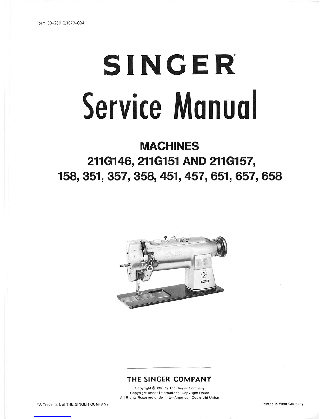
INSTALLATION
Fasten drip pan to table with its left end even
with
left
end
of
cut-out.
Fasten
knee
lifter
bracket
in location
shown
in Fig. 2 Assemble it so that lifter
rod does not strike drip pan. Screw slots in bracket
provide
necessary adjustment. Set stop-stud to stop
the action of knee lifter
as
soon
as
presser
foot is
raised enough to trip hand lever. Screw drain pipe
into drain hole in drippan and attach oil jar as shown.
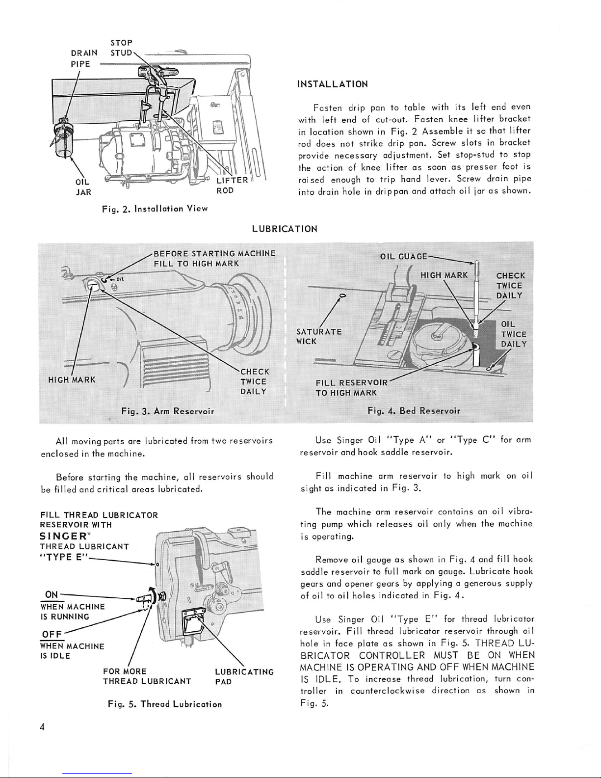
LUBRICATION
•BEFORE
STARTING
MACHINE
FILL
TO
HIGH
MARK
HIGH
MARK
Fig.3.Arm
Reservoir
'CHECK
TWICE
DAILY
All moving parts are lubricated from two
reservoirs
enclosedinthe
machine.
Before storting the machine, oil reservoirs should
be
filled
and
criticol
oreos
lubricated.
FILL
THREAD
LUBRICATOR
RESERVOIR
WITH
SINGER*
THREAD
LUBRICANT
//)
"TYPE
E" I
WHEN
MACHINE
IS
RUNNING
OFF-^"""^'^
WHEN
MACHINE
IS
IDLE
Vii)
FOR
MORE
LUBRICATING
THREAD
LUBRICANT
PAD
Fig.5.Thread
Lubrication
OIL
GUAGE-
SATURATE
WICK
FILL
RESERVOIR'
TO
HIGH
MARK
HIGH
MARK H
Fig.4.Bed
Reservoir
CHECK
TWICE
DAILY
OIL
TWICE
DAILY
i?
.• E
Use Singer Oil
"Type
A" or
"Type
C"
for arm
reservoir
and
hook
saddle
reservoir.
Fill
machine arm
reservoir
to high mark on oil
sightOSindicated in Fig. 3.
The
machine
arm
reservoir
contains
on
oil
vibra
ting
pump
which
releases
oil only when the machine
is
operating.
Remove oil gaugeasshown in Fig. 4 and fill hook
saddle
reservoir to full mark on gouge. Lubricate hook
gears and opener gears by applying a generous supply
of
oiltooil
holes
indicated
in
Fig.
4.
Use Singer Oil
"Type
E"
for thread lubricator
reservoir.
Fill
thread lubricator reservoir through oil
hole in face plate
as
shown in Fig. 5. THREAD LU
BRICATOR
CONTROLLER
MUST
BE
ON WHEN
MACHINEISOPERATING
AND
OFF
WHEN
MACHINE
IS
IDLE.
To
increase
thread
lubrication,
turn
con
troller
in
counterclockwise
direction
as
shown
in
Fig.
5.
CONTROL
PI
VALVE
SET
SCREW
.j
•..|a
ep One)
Fig.
6« Hook
Lubrication
(Step One)
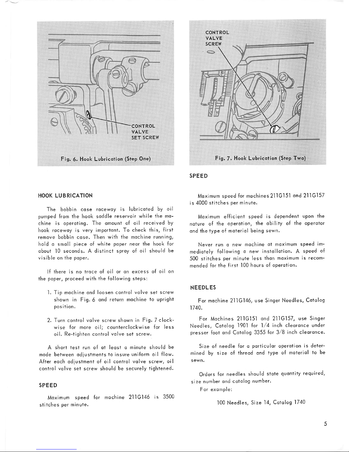
HOOK
LUBRICATION
The bobbin
case
raceway is lubricated by oil
pumped
from
the hook saddle reservoir while the
ma
chine is operating. The amount of oil received by
hook raceway is very important. To check this, first
remove
bobbin
case.
Then
with
the
machine
running,
hold a small
piece
of white paper near the hook for
about 10 seconds. A distinct spray of oil should be
visibleonthe
paper.
If
there
is
no
trace
of
oil
or on
excess
of
oil
on
the paper, proceed with the following
steps:
1. Tip machine and loosen control valve
set
screw
shown in Fig. 6 and return machine to upright
position.
2. Turn control
valve
screw
shown in
Fig.7clock
wise
for more oil;
counterclockwise
for
less
oil.
Re-tighten
control
valve
set
screw.
A
short
test
run
of
at
least
a
minute
should
be
mode between
adjustments
to insure uniform oil flow.
After each adjustment of oil control valve screw, oil
control valve
set
screw should be securely tightened.
SPEED
Maximum
speed for machine 211G146 is 3500
stitches
per minute.
CONTROL
VALVE
SCREW
Fig.
7* Hook Lubrication (Step Two)
SPEED
Maximum
speed for mochines
211G151
and
211G157
is 4000
stitches
per minute.
Maximum
efficient
speed is dependent upon the
nature of the operation, the ability of the operator
and the
type
of materiel being sewn.
Never run a new machine at maximum
speed
im
mediately
followinganew
installation. A speed of
500
stitches
per minute
less
than maximum is recom
mended for
the
first
100
hoursofoperation.
NEEDLES
For machine 211G146,
use
Singer
Needles,
Catalog
1740.
For
Machines
211G151
and
211G157,
use
Singer
Needles, Catalog
1901
for
1/4
inch clearance under
presser foot and Catalog 3355 for
3/8
inch clearance.
Size of needle for a particular operation is
deter
mined
by
size of thread and type of material to be
Orders for needles should state quantity required,
size
number and catalog number.
For example;
100 Needles, Size 14, Catalog 1740
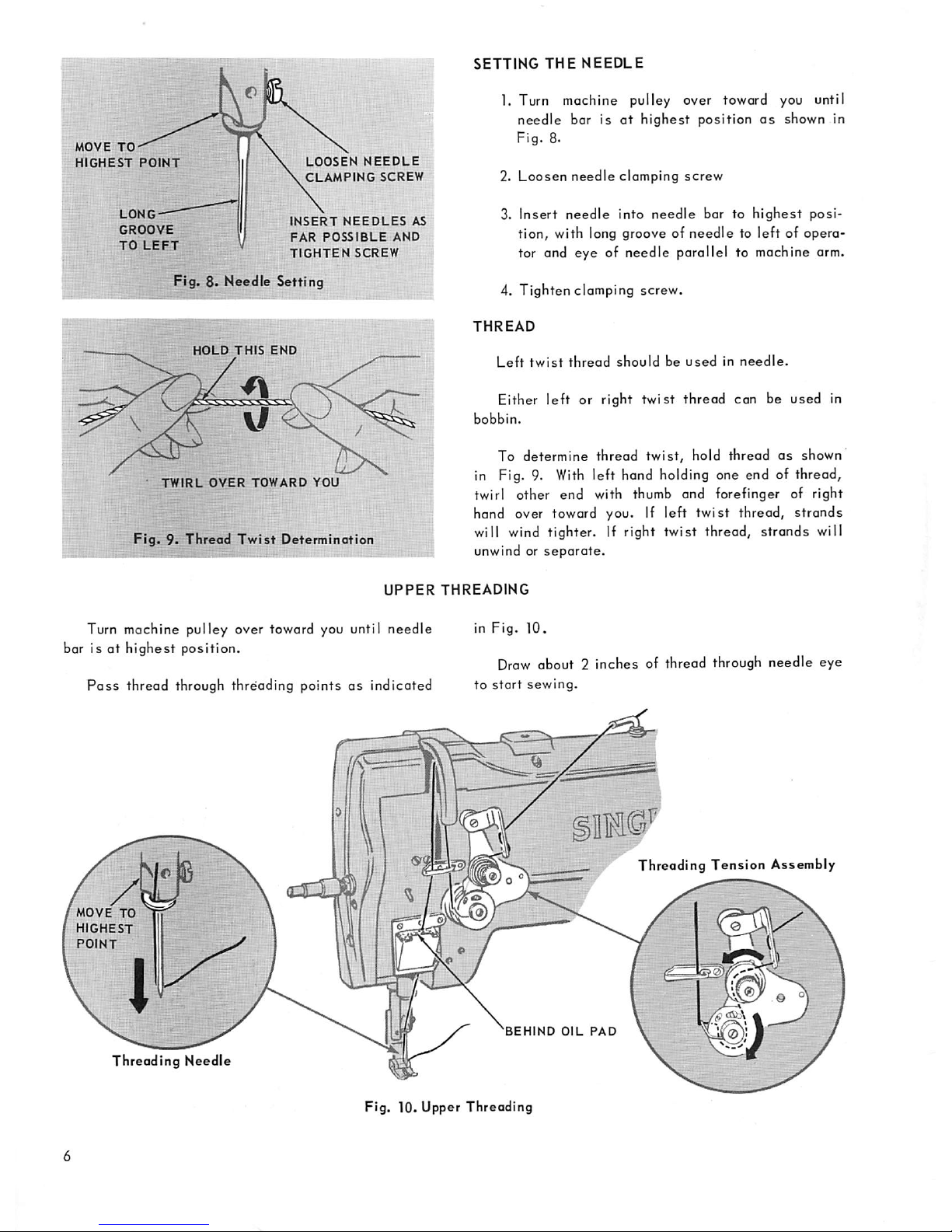
MOVE
TO^
HIGHEST
POINT
LONG-^
GROOVE
TO
LEFT
LOOSEN
NEEDLE
CLAMPING
SCREW
INSERT
NEEDLES
AS
FAR
POSSIBLE
AND
TIGHTEN
SCREW
Fig. 8* Needle Setting
HOLD
THIS
END
TWIRL
OVER
TOWARD
YOU
Fig.9.Thread
Twist
Determination
SETTING
THE
NEEDLE
1. Turn machine pulley over toward you until
needle
bar isathighest
position
as
shown in
Fig.
8.
2.
Loosen
needle
clamping
screw
3. Insert
needle
into
needle
bar to
highest
posi
tion, with long groove of
needletoleft
of opera
tor and eye of needle parallel to machine arm.
4. Tighten clamping screw.
THREAD
Left
twist
thread
should
be
usedinneedle.
Either
left
or right
twist
thread
can be used in
bobbin.
To determine thread
twist,
hold thread
as
shown
in Fig. 9.
With
left hand holding one end of thread,
twirl other end with thumb and forefinger of right
hand over toward you. If left
twist
thread,
strands
will wind tighter. If right twist thread, strands will
unwind or
separate.
UPPER
THREADING
Turn machine pulley over toward you until
needle
bar is ot
highest
position.
Pass
thread through threfading points as indicated
MOVE
TO
HIGHEST
POINT
Threading
Needle
in
Fig.
10.
Draw
about 2 inches of thread through needle eye
to
start
sewing.
Threading
Tension
Assembly
'BEHIND
OIL
PAD
Fig. 10. Upper
Threading

LOWER
THREADING
BOBBIN
REMOVAL
1. Open slide plate in bed of machine
2. Turn machine pulleyover toward you until needle
bar
reaches
highest
position.
3.
Raise
bobbin
latch
and
lift
out
bobbin
as
in
dicatedinFig.
11.
BOBBIN
WINDING
Attach bobbin winder to
table
with driving pulley
in front of
beltasshowninFig.
12.
Securely place bobbin on bobbin winder spindle.
Pass
thread through thread guide, then around and
between
tension
discs
as
shown.
Wind
thread
clock
wise
around
bobbin a few
times
as
indicated
in
Fig.
12.
Move
bobbin winder pulley over against machine
belt
and
start
machine.
The
amount
of
thread
to
be
wound
on
bobbin
is
regulatedbyscrew B, Fig.
12.
To
wind
more
thread
on bobbin, turn screw B inward. For
less
thread on
bobbin, turn screw B outward. This screw should be
regulated to stop bobbin winder spindle when thread
on
bobbinis1/16
inch
shortofbobbin
rim.
If thread winds unevenly on bobbin, loosen tension
bracket screw A, Fig. 12, and
move
bracket to right
or
lefttoobtain
even
winding.
Adjusting knurled nut C, Fig.
12,
regulates tension
of thread being
wound
on
bobbin.
For fine thread,
use
light
tension.
Bobbins
maybewound
while machine is stitching.
BOBBIN
REPLACEMENT
Place
bobbinoncenter
stud
with
thread
wound in
counterclockwise
direction
as shown in
Fig.
13. Draw
about
2 or 3
inchesofthread
from
bobbin.
Bpf''
LIFT
LATCH
LIFT
OUT
BOBBIN
Fig. 11. Bobbin Removal
Fig.
12. Bobbin Winding
PLACE
BOBBIN
ON
CENTER
STUD
CLOSE
LATCH
•
DIRECTION
OF
THREAD
AROUND
BOBBIN
Fig.
13. Bobbin Replacement
 Loading...