

5-V Low-Drop Fixed Voltage Regulator TLE 4278 G
Features
• Output voltage tolerance ≤±2%
• Very low current consumption
• Separated reset and watchdog output
• Low-drop voltage
• Watchdog
• Adjustable watchdog activating threshold
• Settable reset threshold
• Overtemperature protection
• Reverse polarity protection
• Short-circuit proof
• Suitable for use in automotive electronics
• Wide temperature range
P-DSO-14-4
Type Ordering Code Package
TLE 4278 G Q67006-A9291 P-DSO-14-4 (SMD)
Functional Description
The TLE 4278 is a monolithic integrated low-drop fixed-voltage regulator which can
supply loads up to 200 mA. Th e device is available in the P-DSO-14-4 package. It is
designed to supply micropro cessor syste ms under the severe co nditions of auto motive
applications and there fore is equi pped with additional protection f unctions a gainst ove r
load, short circuit and over temperatu re. Of course the TLE 4278 can also be used in
other applications where a stabilized voltage is required.
An input voltage
in the range of 5.5 V ≤ VI≤ 45 V is regulated to V
I
=5V within an
Qrated
V
accuracy of ±2%.
T
The device operates in the wide temperature range of
= – 40 to 150 °C.
j
Semiconductor Group 1 1998-11-01

TLE 4278 G
Two additional features of the TLE 4278 are a load dependent watchdog function as well
as a power on reset and under voltage reset function with an adjustable reset delay time
and adjustable reset switching threshold.
The watchdog function monitors whether the microcontroller is functioning appropriately,
including time base failure s. In the case that there is no positive-going edge within a
certain pulse repetition-time the watchdog output is set to LOW. Programming of the
max. repetition time is done by the reset delay capac itor so that no additional external
components are necessary. To prevent the microcontroller from a automatic reset in
case of missing pulses, the watchdog output WO is separated from the reset output RO
for the TLE 4278. The watchdog output can be used as an interrupt signal for the
microcontroller. Pin WO can be externally connected to pin RO.
When the controller is set to sl eep mode or low power mode its current consumption
drops and no watchdog pulses are create d. In ord er to prev ent th e mic r oco ntrol ler from
unnecessary wake ups due to missing pulses at pin WI the watchdog feature can be
disabled as a function of the load. The switch off threshold is set by an external resistor
to pin WADJ. This function can also be used as a timer, which periodically wakes up the
controller. Therefore the pin WADJ has to be connected to the output Q.
The power on reset feature is necessary for a defined start of the microprocessor when
switching on the application. For a certain delay time after the output voltage of the
regulator has surpassed the reset threshold, a reset signal is generated. The delay time
is set by an external delay capacitor. The under voltage reset circuit supervises the
output voltage. In case VQ falls below the reset threshold the reset output is set LOW
after a short reaction time. The reset LOW signal is generated down to an output voltage
VQ of 1 V. In addition the reset switching threshold can be adjusted by an external
voltage divider. This feature is useful with microprocessors which guarantee a safe
operation down to voltages below the internally set reset threshold of 4.65 V typical.
Semiconductor Group 2 1998-11-01
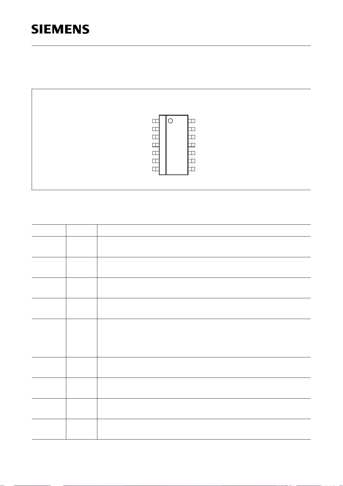
Pin Configuration
(top view)
TLE 4278 G
P-DSO-14-4
WO
WADJ
GND
GND
GND
D
RADJ
1
2
3
4
5
6
7
AEP02113
14
13
12
11
10
RO
V
Ι
GND
GND
GND
9
V
Q
8
W
Ι
Figure 1
Pin Definitions and Functions
Pin Symbol Function
1WOWatchdog Output; the open collector output is connected to the
5-V output via an integrated resistor of 30 kΩ.
2WADJWatchdog Adjust; an external resistor to GND determine the
watchdog activating threshol d.
3, 4, 5,
GND Ground
10, 11, 12
6DReset Delay; connect a capacitor to ground for delay time
adjustment.
7RADJReset Switching Threshold Adjust; for setting the switching
threshold, connect a voltage divider from output to ground. If this
input is connected to ground, the reset is triggered at the internal
threshold.
8WIWatchdog input; positive-edge-triggered input for monitoring a
microcontroller.
9
V
Q
5-V output voltage; block to ground with min. 10 µF capacitor,
ESR < 10 Ω at 10 kHz.
13
V
I
Input voltage; block to ground directly on the IC with ceramic
capacitor.
14 RO Reset output; the open collector output is connected to the
5-V output via an integrated resistor of 30 kΩ.
Semiconductor Group 3 1998-11-01
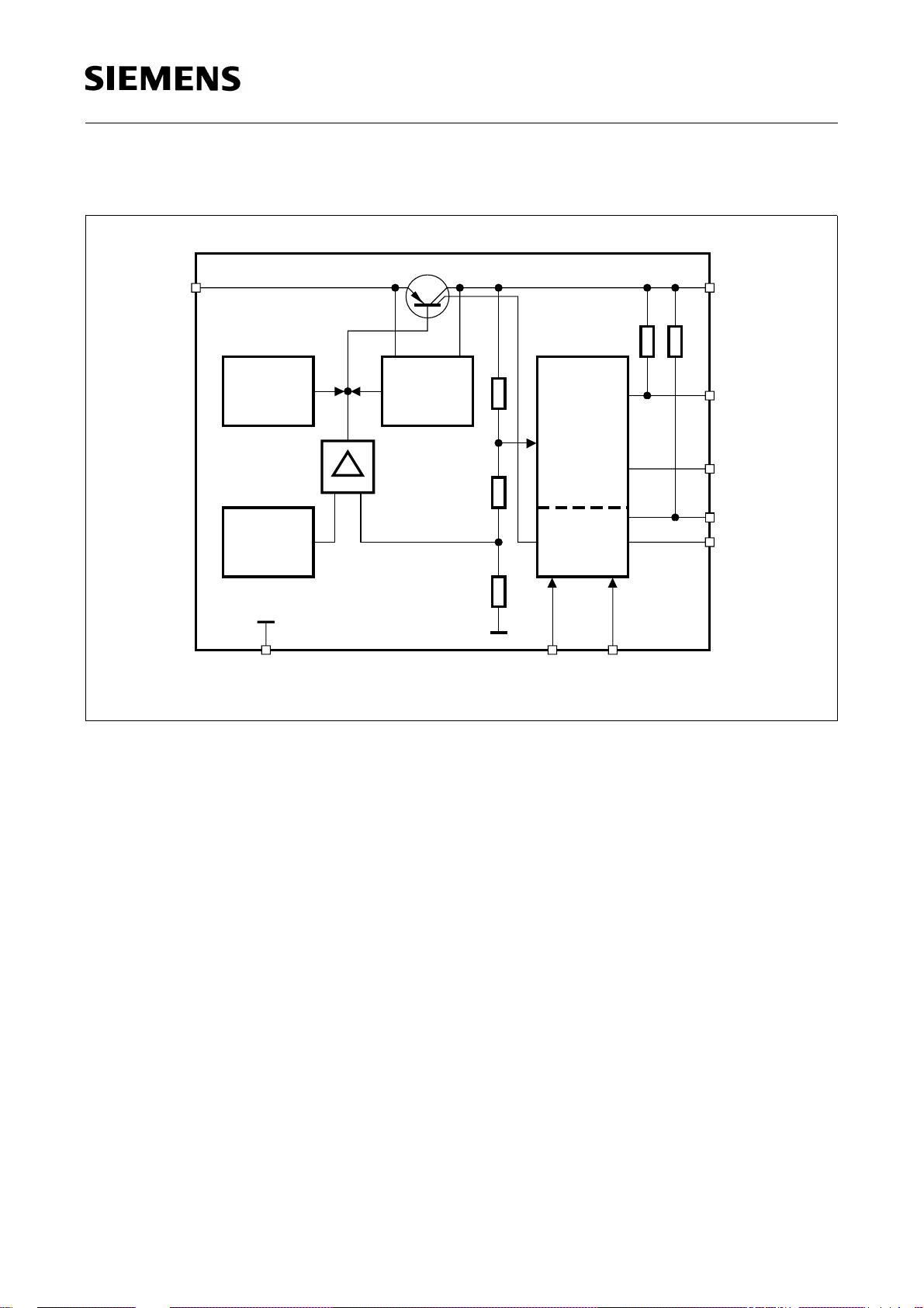
Block Diagram
TLE 4278 G
13
V
Ι
Temperature
Sensor
Protection
Circuit
12
14
V
Q
RO
Reset
Bandgap
Reference
3-5, 10-12
GND
Generator
Control
+
Amplifier
-
7
1
Watchdog
2
WADJ
W
8
Ι
6
AEB02114
RADJ
WO
D
Figure 2
Semiconductor Group 4 1998-11-01
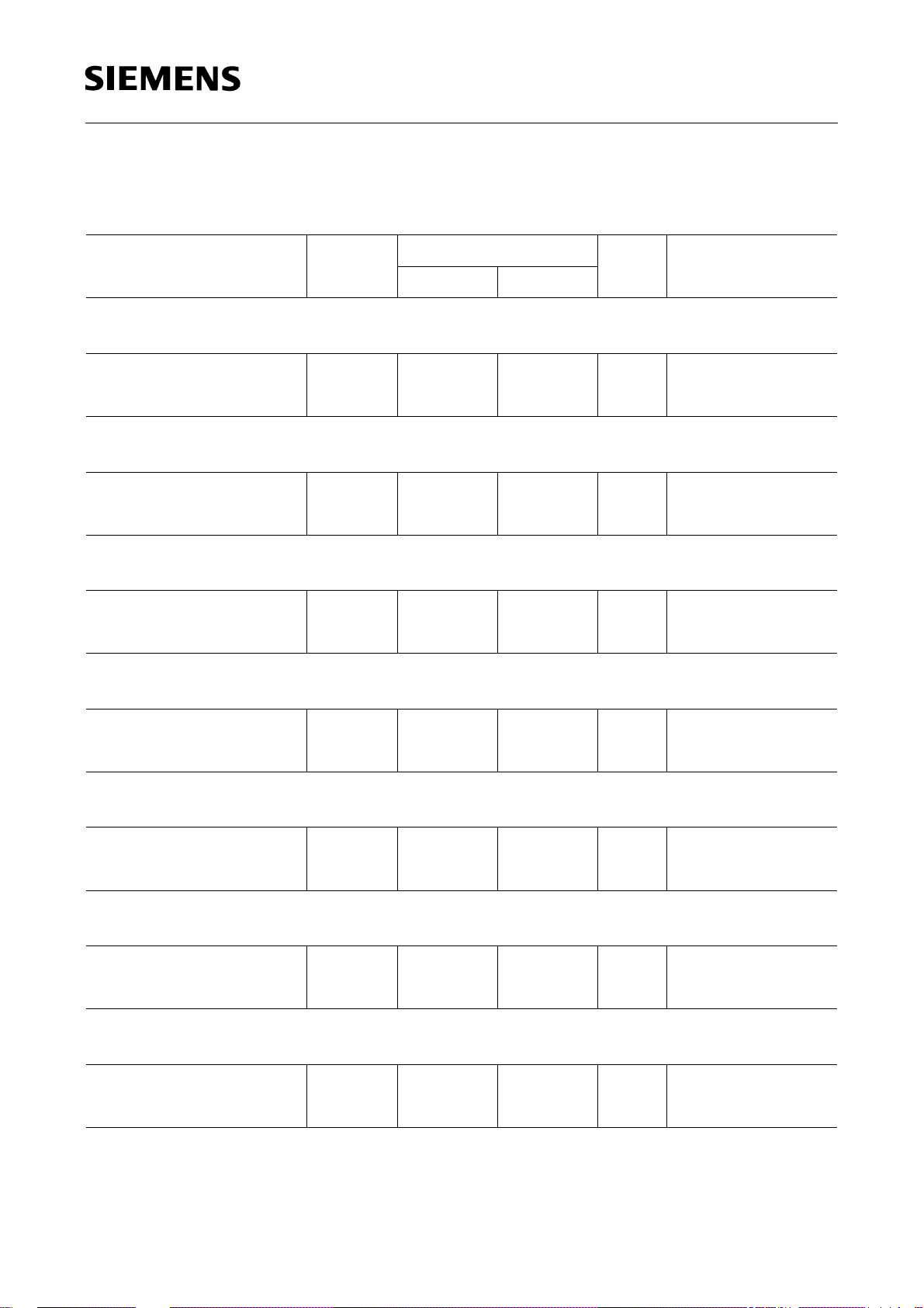
Absolute Maximum Ratings
T
= – 40 to 150 °C
j
Parameter Symbol Limit Values Unit Notes
min. max.
TLE 4278 G
Input Voltage
V
I
Voltage V
Current
Output Voltage
V
Q
I
Voltage V
Current
I
Reset Output RO
Voltage
Current
V
I
Reset Delay D
Voltage
Current
V
I
I
Q
RO
D
I
Q
RO
D
– 42 45 V –
– – mA Internally limited
– 1 25 V –
– – mA Internally limited
– 0.3 25 V –
– 5 5 mA –
– 0.3 7 V –
– 2 2 mA –
Reset Switching Threshold Adjust RADJ
Voltage
Current
V
I
RADJ
RADJ
– 0.3 7 V –
– – mA Internally limited
Watchdog Input WI
Voltage
Current
V
I
WI
WI
– 0.3 7 V –
– – mA Internally limited
Watchdog Output WO
Voltage
Current
Semiconductor Group 5 1998-11-01
V
I
WO
WO
– 0.3 25 V –
– 5 5 mA –
Absolute Maximum Ratings (cont’d)
T
= – 40 to 150 °C
j
Parameter Symbol Limit Values Unit Notes
min. max.
Watchdog Adjust WADJ
TLE 4278 G
Voltage
Current
V
WADJ
I
WADJ
– 0.3 7 V –
– – mA Internally limited
Ground GND
Current
I
GND
– 100 50 mA –
Temperatures
Junction temperature
Storage temperature
T
j
T
stg
– 50 150 °C–
– 50 150 °C–
Note: ESD protection according to MIL Std. 883: ± 2 kV.
Maximum ratings are abs olute ratings; exceeding any one of th ese values may
cause irreversible damage to the integrated circuit.
Operating Range
Parameter Symbol Limit Values Unit Notes
min. max.
Input voltage
Junction temperature
V
T
I
j
5.5 45 V –
– 40 150 °C–
Thermal Resistance
Junction ambient
Junction pin
R
R
thj-a
thj-pin
– 70 K/W Measured to pin 4
– 25 K/W Measured to pin 4
Note: In the operating range the functions given in the circuit description are fulfilled.
Semiconductor Group 6 1998-11-01
 Loading...