

Page 1
MAMMOMAT Novation
Planning Guide
DR
SP
System
with DROC (Direct Ray Operation Console)
© Siemens AG 2003
The reproduction, transmission or
use of this document or its contents
is not permitted without express
written authority. Offenders will be
liable for damages. All rights,
including rights created by patent
grant or registration of a utility
model _or_ design,_are_ reserved.
English
Print No.: SPB7-250.891.01.04.02 Doc. Gen. Date: 08.05
Replaces: SPB7-250.891.01.03.02
Page 2

0 - 2 Revision
Chapter Page Revision
all all 01
all all 02
all all 03
all all 04
Document revision level
The document corresponds to the version/revision level effective at the time of system delivery.
Revisions to hardcopy documentation are not automatically distributed.
Please contact your local Siemens office to order current revision levels.
Disclaimer
The installation and service of equipment described herein is to be performed by qualified personnel
who are employed by Siemens or one of its affiliates or who are otherwise authorized by Siemens or
one of its affiliates to provide such services.
Assemblers and other persons who are not employed by or otherwise directly affiliated with or authorized by Siemens or one of its affiliates are directed to contact one of the local offices of Siemens or
one of its affiliates before attempting installation or service procedures.
MAMMOMAT Novation
Rev. 04 08.05 CS SD 21 Medical Solutions
DR
SPB7-250.891.01 Page 2 of 4 Siemens AG
Page 3

Contents 0 - 3
Page
1 _______General Notes _________________________________________________ 1 - 1
General Notes . . . . . . . . . . . . . . . . . . . . . . . . . . . . . . . . . . . . . . 1 - 1
Safety . . . . . . . . . . . . . . . . . . . . . . . . . . . . . . . . . . . . . . . . . . 1 - 2
System Overview . . . . . . . . . . . . . . . . . . . . . . . . . . . . . . . . . . . . 1 - 3
MAMMOMAT Novation
Network . . . . . . . . . . . . . . . . . . . . . . . . . . . . . . . . . . . . . . . . .1 - 5
Software Installation . . . . . . . . . . . . . . . . . . . . . . . . . . . . . . . . . . . 1 - 5
DICOM . . . . . . . . . . . . . . . . . . . . . . . . . . . . . . . . . . . . . . . . .1 - 5
2 _______Room Planning ________________________________________________ 2 - 1
Room Planning Example 1 . . . . . . . . . . . . . . . . . . . . . . . . . . . . . . . 2 - 1
Room Planning Example 2 . . . . . . . . . . . . . . . . . . . . . . . . . . . . . . . 2 - 2
Stand Dimensions . . . . . . . . . . . . . . . . . . . . . . . . . . . . . . . . . . . . 2 - 3
Radiation Shield Dimensions (Option) . . . . . . . . . . . . . . . . . . . . . . . . . 2 - 4
Installing the Control Console on the Wall or on a Table . . . . . . . . . . . . . . . . 2 - 5
Acquisition Workstation . . . . . . . . . . . . . . . . . . . . . . . . . . . . . . . . . 2 - 6
DR
. . . . . . . . . . . . . . . . . . . . . . . . . . . . . . . . 1 - 4
3 _______Preparation for Installation _______________________________________ 3 - 1
Stand Floor Plate . . . . . . . . . . . . . . . . . . . . . . . . . . . . . . . . . . . . 3 - 1
(The floor plate is designed to also be the unit base) . . . . . . . . . . . . . . . . 3 - 1
Radiation Shield Floor Plate (Option) . . . . . . . . . . . . . . . . . . . . . . . . . . 3 - 2
On-site Electrical Installation . . . . . . . . . . . . . . . . . . . . . . . . . . . . . . 3 - 3
On-site Electrical Installation . . . . . . . . . . . . . . . . . . . . . . . . . . . . . . 3 - 4
4 _______System Connections ____________________________________________ 4 - 1
Remarks Regarding Laying of Cables. . . . . . . . . . . . . . . . . . . . . . . . . . 4 - 1
Fixpoint Overview . . . . . . . . . . . . . . . . . . . . . . . . . . . . . . . . . . . . 4 - 2
Fixpoint List . . . . . . . . . . . . . . . . . . . . . . . . . . . . . . . . . . . . . . .4 - 3
List of Fixpoints Used . . . . . . . . . . . . . . . . . . . . . . . . . . . . . . . . . . 4 - 3
5 _______Technical Data _________________________________________________ 5 - 1
Electrical Data . . . . . . . . . . . . . . . . . . . . . . . . . . . . . . . . . . . . . 5 - 1
Environmental Conditions . . . . . . . . . . . . . . . . . . . . . . . . . . . . . . . 5 - 1
Dimensions, Weight and Heat Dissipation . . . . . . . . . . . . . . . . . . . . . . . 5 - 1
Packaging and Transport Routes . . . . . . . . . . . . . . . . . . . . . . . . . . . . 5 - 2
Paint Colors . . . . . . . . . . . . . . . . . . . . . . . . . . . . . . . . . . . . . . .5 - 2
6 _______Changes to Previous Version_____________________________________ 6 - 1
Siemens AG SPB7-250.891.01 Page 3 of 4 MAMMOMAT Novation
Medical Solutions Rev. 04 08.05 CS SD 21
DR
Page 4

0 - 4 Contents
MAMMOMAT Novation
Rev. 04 08.05 CS SD 21 Medical Solutions
DR
SPB7-250.891.01 Page 4 of 4 Siemens AG
Page 5

General Notes 1
1 - 1
General Notes 1
- With distribution of these revision level, all preceding planning guides (PGs), Speed Infos and drafts
lose their validity.
- All layouts issued by the Planning Departments must bear a note referring to the installation and
delivery conditions of Siemens Medical Engineering. The installation and delivery conditions must
be submitted with the layouts.
- Unless otherwise specified, all dimensions are indicated in "mm".
- The symbol indicates a change (see revision status).
- Orientation points
Points specific to system components to which reference is made when positioning system
components to each other or in the room.
The isocenter of a radiographic system is always illustrated as the orientation point.
- Fixpoints
Clearly marked points on system components, installation ceiling, walls or floor on which cable
outlets are located.
Illustration in the drawings: octagon with letter/number-combination.
The cable lengths specify the maximum fixpoint distances and thus the maximum distances
between the individual system components.
- Room height
The room height is the distance measured from the top surface of the floor to the bottom surface of
the ceiling structural elements (Unistrut rails) (bottom surface of drop ceiling).
- Room lighting
According to DIN 68 68-57 (international standard in preparation), the lighting in rooms in which
image playback devices (monitors) are used for diagnosis, the following requirements must be
met:
adjustable, no anti-glare screen, reproducible adjustment of the lighting (e.g. dimmer with
scale),
no glare or reflection from windows, lights and light boxes in the standard working position of
the monitors.
Hotline + 49 (9191) 18 - 8080
Siemens AG SPB7-250.891.01 Page 1 of 6 MAMMOMAT Novation
Medical Solutions Rev. 04 08.05 CS SD 21
DR
Page 6

1 - 2 General Notes
Safety 1
- The provisions of the relevant fire safety regulations must be observed for the premises.
- The system has been developed according to EN 60601 - 1.
- Minimum dimensions (e.g. room heights, safety distances) indicated in the planning guides are
marked "min."
- Basic resistance to electromagnetic sources of interference.
Result of lightning discharges.
The protection targets of the different lightning protection areas up to the unit connection are also
specified in the IEC 1024, DIN 48810, VDE 0675 and in the DEMVT recommendations.
MAMMOMAT Novation
Rev. 04 08.05 CS SD 21 Medical Solutions
DR
SPB7-250.891.01 Page 2 of 6 Siemens AG
Page 7
General Notes 1 - 3
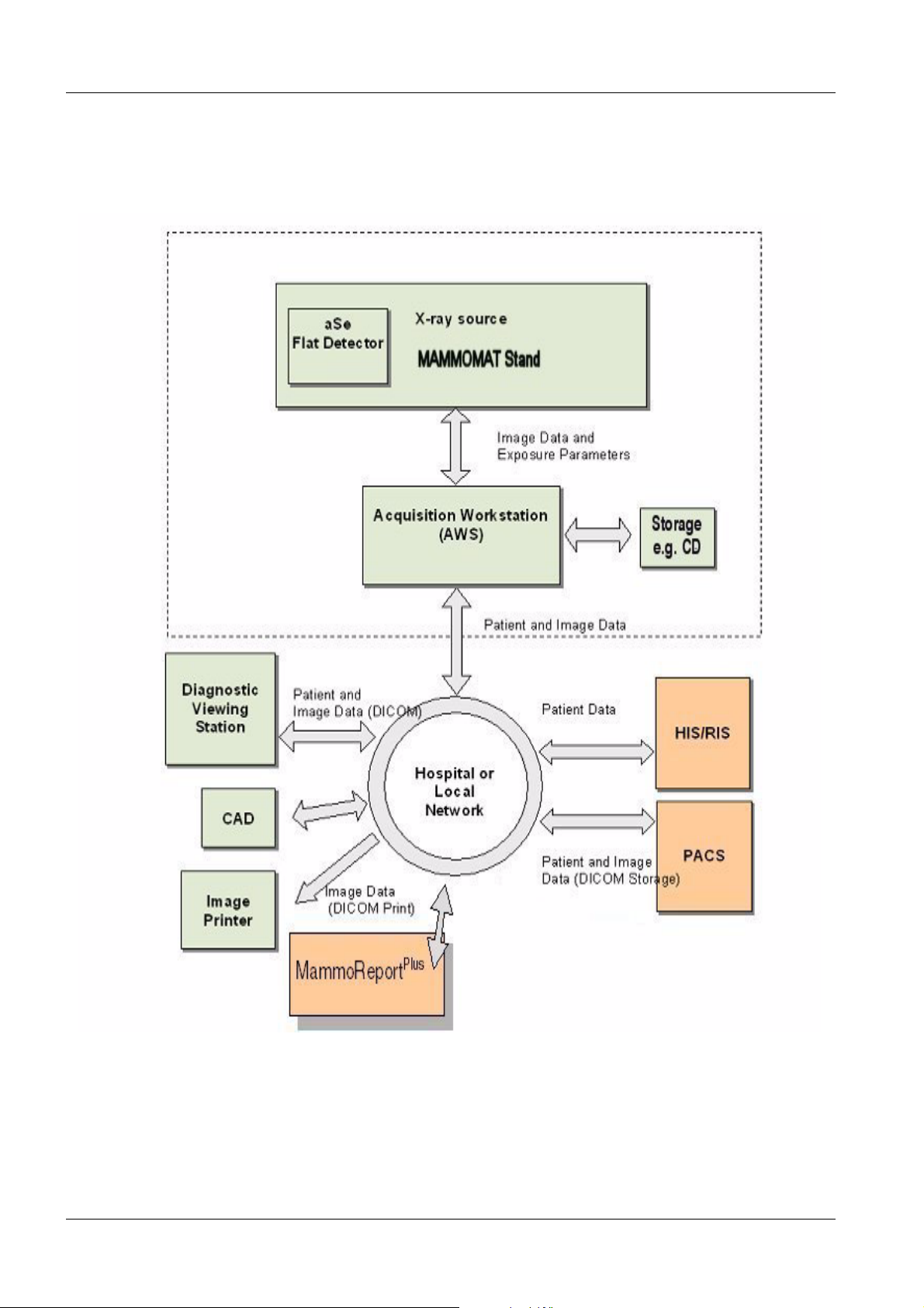
System Overview 1
Siemens AG SPB7-250.891.01 Page 3 of 6 MAMMOMAT Novation
Medical Solutions Rev. 04 08.05 CS SD 21
DR
Page 8
1 - 4 General Notes
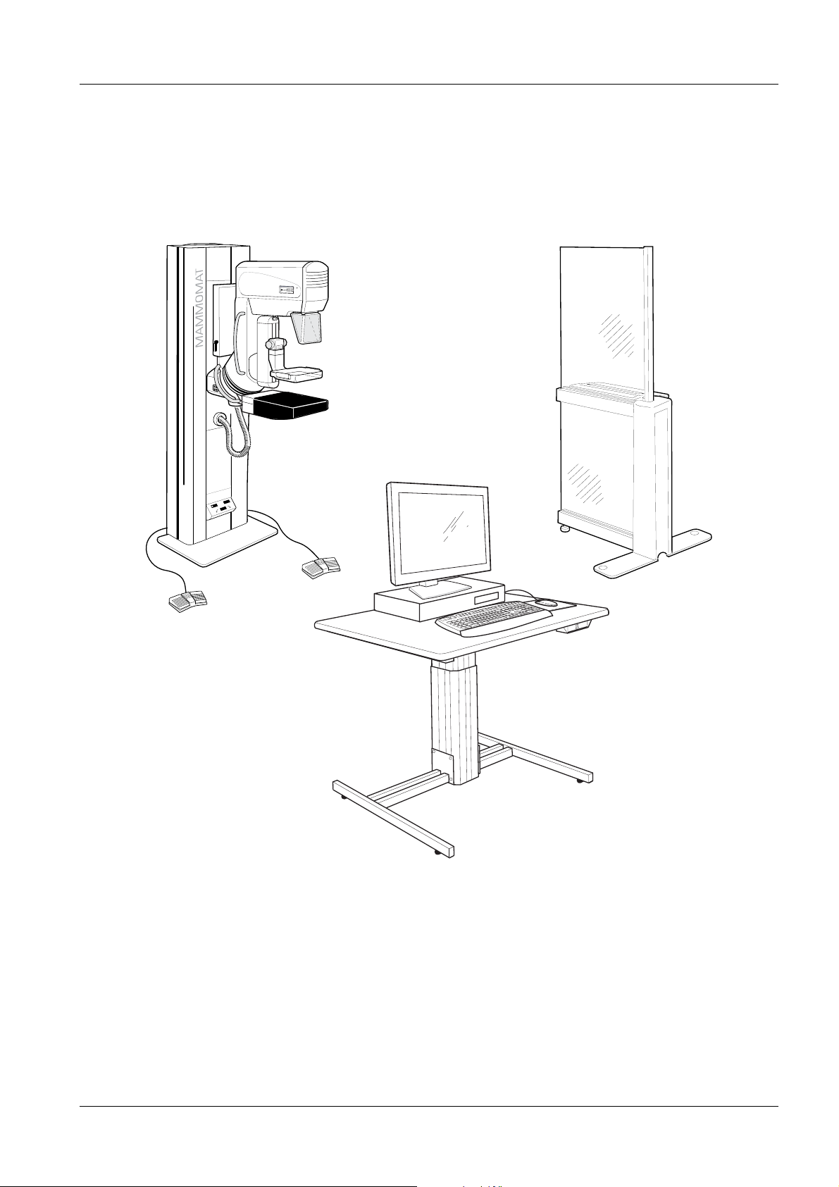
MAMMOMAT Novation
DR
Overview of the MAMMOMAT system
1
MAMMOMAT Novation
Rev. 04 08.05 CS SD 21 Medical Solutions
DR
SPB7-250.891.01 Page 4 of 6 Siemens AG
Page 9

General Notes 1 - 5
Network 1
The acquisition workstation supports the TCP/IP protocol. Due to the required data volumes, we recommend a network of 100 MB/s. Please note that all required network cables, as well as the required
power outlets must be available on site. If needed, an outside contractor must be obtained on site.
Software Installation 1
The acquisition workstation is shipped with the software already preinstalled.
DICOM 1
For detailed information on the DICOM, see PG TDIT-000.891.02...,
which can be found on the Intranet under: CS/ForService/Planning/General...
Siemens AG SPB7-250.891.01 Page 5 of 6 MAMMOMAT Novation
Medical Solutions Rev. 04 08.05 CS SD 21
DR
Page 10

1 - 6 General Notes
This page intentionally left blank.
MAMMOMAT Novation
Rev. 04 08.05 CS SD 21 Medical Solutions
DR
SPB7-250.891.01 Page 6 of 6 Siemens AG
Page 11

Room Planning 2
2 - 1
Room Planning Example 1 2
2 cable conduits (each 2 m) included
in the shipment for "on-the-floor"
laying of cables
For additional cable conduits, see
*2
Focus
*1 min. 150 mm if the unit is not secured to the
*3
*3 For safety reasons, the acquisition workstation must be set up outside the area,
per IEC 60601-1-1.
floor (in a special service situation, the generator must be swung out from behind at the stand;
for this, the stand must be moved 500 mm away
from the wall).
min. 500 mm if the unit is secured to the floor.
*2 If needed, additional cable conduits, Part No. 64
38 795 X041E, can be ordered for the connection between the stand and the radiation shield.
NOTE
Siemens AG SPB7-250.891.01 Page 1 of 6 MAMMOMAT Novation
Medical Solutions Rev. 04 08.05 CS SD 21
The room planning example shows one possible arrangement of the units.
Other arrangements are possible, provided the necessary unit distances
based on the available cable lengths are maintained.
DR
Page 12

2 - 2 Room Planning
Room Planning Example 2 2
2 cable conduits (each 2 m) included
in the shipment for "on-the-floor"
laying of cables
For additional cable conduits, see
*2
Focus
*1 min. 150 mm if the unit is not secured to the
floor (in a special service situation, the generator must be swung out from behind at the stand;
for this, the stand must be moved 500 mm away
from the wall).
min. 500 mm if the unit is secured to the floor.
*2 If needed, additional cable conduits, Part No. 64
38 795 X041E, can be ordered for the connection between the stand and the radiation shield.
*3
*3 For safety reasons, the acquisition workstation must be set up outside the area,
per IEC 60601-1-1.
NOTE
The room planning example shows one possible arrangement of the units.
Other arrangements are possible, provided the necessary unit distances
based on the available cable lengths are maintained.
MAMMOMAT Novation
Rev. 04 08.05 CS SD 21 Medical Solutions
DR
SPB7-250.891.01 Page 2 of 6 Siemens AG
Page 13

Room Planning 2 - 3
Stand Dimensions 2
Focus
Siemens AG SPB7-250.891.01 Page 3 of 6 MAMMOMAT Novation
Medical Solutions Rev. 04 08.05 CS SD 21
DR
Page 14

2 - 4 Room Planning
Radiation Shield Dimensions (Option) 2
MAMMOMAT Novation
Rev. 04 08.05 CS SD 21 Medical Solutions
DR
SPB7-250.891.01 Page 4 of 6 Siemens AG
Page 15

Room Planning 2 - 5
Installing the Control Console on the Wall or on a Table 2
If the system is not equipped with the optional radiation shield, install the control console on the wall or
on a table that is located behind one of the on-site radiation shields. The parts required for vertical or
horizontal installation of the control console on the wall are included in the shipment.
NOTE
Installing the Control Console on the Wall (two possibilities)
Screw anchors and screws are not included in the shipment. Please obtain
these locally and make sure that they are suitable for the particular type of wall
construction.
Cable conduit, on-site
Installation of the Control Console on a Table
Siemens AG SPB7-250.891.01 Page 5 of 6 MAMMOMAT Novation
Medical Solutions Rev. 04 08.05 CS SD 21
DR
Page 16

2 - 6 Room Planning
Acquisition Workstation 2
Comprised of: 18" color display, PC, keyboard, mouse
Table (option)
1 : 20
The height of table for the acquisition workstation can be adjusted using a motor.
NOTE
MAMMOMAT Novation
Rev. 04 08.05 CS SD 21 Medical Solutions
If the table (option) for the acquisition workstation is not ordered, it must be
provided by the customer.
DR
SPB7-250.891.01 Page 6 of 6 Siemens AG
Page 17

Preparation for Installation 3
3 - 1
Stand Floor Plate 3
(The floor plate is designed to also be the unit base) 3
If due to local regulations (e.g. in earthquake regions) or due to the quality of the floor covering, floor
installation is required, the stand can be installed using heavy-duty expansion bolts or threaded rods
(with a counter-plate). Heavy-duty expansion bolts and threaded rods must be obtained locally.
Cable lead-in from the floor only if the on-the-floor cable conduits included in the
shipment cannot be used. For on-the-floor cable conduits, see Pages 2-1, 2-2
Slots for cable
lead-in
Cable lead-in from the floor left or
right. Obtain cable conduits on site.
1 : 10
View Z
See Page 3-2
*1 See *1 Pages 2-1, 2-2
The max. pull forces that occur per mounting point: 1.5 kN
Siemens AG SPB7-250.891.01 Page 1 of 4 MAMMOMAT Novation
Medical Solutions Rev. 04 08.05 CS SD 21
DR
Page 18

3 - 2 Preparation for Installation
Radiation Shield Floor Plate (Option) 3
The radiation shield must always be installed on the floor in accordance with IEC 60601-2-32.
Z
Max. pull forces that occur per
mounting point: 1.5 kN
For mounting example, see below
1 : 10
Installation example
Z (1 : 2)
Leveling screw
Cover plate
Room for cable lead-in in floor
Floor plate
Caulk all around using
sanitary silicon
E.g. Hilti heavy duty anchor bolts
HSL M8/20
If safety screws are used, the
manufacturer’s specifications
and instructions must be
observed
With installation on the a solid
floor, cut out the floor covering.
Concrete quality for the solid
floor, min. C20/25
Leveling screw
1 : 2
Mounting materials must be
obtained locally.
MAMMOMAT Novation
Rev. 04 08.05 CS SD 21 Medical Solutions
DR
SPB7-250.891.01 Page 2 of 4 Siemens AG
Page 19

Preparation for Installation 3 - 3
On-site Electrical Installation 3
Recommendation for an on-site power distributor per DIN VDE 0100-710 or national regulations
Must be constructed on site
Power cable for radiation
To external conductive parts
FI switch, 63 A/I
current and pulsed DC fault currents (recommendation:
Siemens FI 5SZ3 466 0KG05 all current sensitive or
ABB No. F 804 - 63 /0.03. Can be ordered from ABB
Stotz - contact Heidelberg, Tel. 06221 701-00). For other
power line voltages, an appropriate FI switch must be
obtained locally.
System power switch
N 30 mA, UN = 400/415 V ∼ for AC
∆
Emergency off switch with latch mechanism
SIEMENS
On/off switch with pilot lamp
Data corresponds to free lengths in m
This is a dedicated power cable. Thus the following may not be connected:
• Electrical systems
• Heating/air conditioning units
• Elevators
• General electrical equipment
Siemens AG SPB7-250.891.01 Page 3 of 4 MAMMOMAT Novation
Medical Solutions Rev. 04 08.05 CS SD 21
DR
Page 20

3 - 4 Preparation for Installation
On-site Electrical Installation 3
Recommendation for an on-site power distributor per DIN VDE 0100-710 or national regulations
Must be constructed on site
2-phase
Power cable for radiation
SIEMENS
To external conductive parts
FI switch 63 A/I
pulsed DC fault currents (recommendation: Siemens FI
5SZ3 466 0KG05 all current sensitive or ABB No. F 804
- 63 /0.03. Can be ordered from ABB Stotz - contact
Heidelberg, Tel. 06221 701-00). For other line voltages,
an appropriate FI switch must be obtained locally.
System power switch
N 30 mA, UN = 400/415 V ∼ for AC and
∆
Emergency off switch with latch mechanism
SIEMENS
On/off switch with pilot lamp
Data corresponds to free lengths in m
This is a dedicated power cable. Thus the following may not be connected:
• Electrical systems
• Heating/air conditioning units
• Elevators
• General electrical equipment
MAMMOMAT Novation
Rev. 04 08.05 CS SD 21 Medical Solutions
DR
SPB7-250.891.01 Page 4 of 4 Siemens AG
Page 21

System Connections 4
4 - 1
Remarks Regarding Laying of Cables 4
Recommendation for Laying Cables
Cable trough depth: 60 mm
if there are cross-overs, it may be necessary to provide greater depth.
Lay high voltage cables and power cables separately from signal cables and video cables (if possible,
provide shielding measures).
Absolutely observe:
Avoid creating cable coils, avoid cable cross-overs.
• Lay in separate conduits or closed cable troughs.
• If laying in open cable troughs, lay cables separately using metal separators or a similar device.
Metal separators
Cable trough
Siemens AG SPB7-250.891.01 Page 1 of 4 MAMMOMAT Novation
Medical Solutions Rev. 04 08.05 CS SD 21
DR
Page 22

4 - 2 System Connections
Fixpoint Overview 4
*1 Mains power on/off switch is necessary in the installation room, to be able to switch off the entire
power to the system, for service and maintenance purposes.
MAMMOMAT Novation
Rev. 04 08.05 CS SD 21 Medical Solutions
DR
SPB7-250.891.01 Page 2 of 4 Siemens AG
Page 23

System Connections 4 - 3
Fixpoint List 4
Wiring
Har-
ness
No.
1VKP1 ⎯⎯⎯⎯Power cable, on site
2 P1 P1a 500 1 1/4 Ø 30 10
3P1D3 45 3/4Ø 15 7.5
4D3
5 P1 Lamp ⎯ 1/2 Ø 10 ⎯
6P1
from
Fix-
point
to
Fixpoint
Clinic
network
Door
switch
Cable Chan-
nel Cross
Section in
2
mm
45 3/4 Ø 15 3.5
⎯ 1/2 Ø 10 ⎯
Con-
duit, dia.
in
inches
Minimum
Opening
in mm
Maximum
Fixpoint
Distance
in m
Remark
Control console cable,
shipped length: 11.5 m
Fiber optic cable,
shipped length: 10 m
Ethernet cable,
shipped length: 3.5 m
On-site cable,
3 x 1.5 mm, shielded
On-site cable,
3 x 1.5 mm, shielded
List of Fixpoints Used 4
Fixpoint Subsystem Remark
D3 Acquisition Workstation Floor fixpoint
P1 MAMMOMAT Novation
P1a Radiation shield Floor fixpoint
VK Power distributor box Wall fixpoint
DR
Floor fixpoint
Siemens AG SPB7-250.891.01 Page 3 of 4 MAMMOMAT Novation
Medical Solutions Rev. 04 08.05 CS SD 21
DR
Page 24

4 - 4 System Connections
This page intentionally left blank.
MAMMOMAT Novation
Rev. 04 08.05 CS SD 21 Medical Solutions
DR
SPB7-250.891.01 Page 4 of 4 Siemens AG
Page 25

Technical Data 5
5 - 1
Electrical Data 5
Power line connection 1~/2~208, 230, 240, 277 V, ±10%, 50/60 Hz
2~400 V, ±10%, 50/60 Hz
Input fusing: 25 A
Power cable Recommended cable cross section: 6 mm
2
Internal power line resistance, Ri
Fusing (internal) 30 A at 208, 230, 240, 277 and 400 V
I max. 40 A at 230 V, 35 A at 400 V (2-phase)
Power consumption Short-term power consumption,
approx. 10 kVA
Power factor (cos ϕ) 0.6 at 230 V
Connection value 4.6 kVA at 230 V
U
208
230
240
277
400
[V]
N
Long-term load,
approx. 0.8 kVA
Ri
max
0.45
0.50
0.60
0.65
0.85
[Ω]
Environmental Conditions 5
Adm. ambient temperature + 20
Operation Transport/Storage
MAMMOMAT
° ... + 30° C- 10° ... + 70° C+ 10° ... + 40° C
Transport/Storage
Detector in packaging
Adm. rel. humidity
(non condensing)
30% ... 70% 10% ... 95% 10% ... 80%
Dimensions, Weight and Heat Dissipation 5
Dimensions
(W x D x H)
[mm]
Stand with floor plate and generator ⎯ approx. 360 approx. 800
Control console 520 x 200 x 80 approx. 4 approx. 80
Radiation shield with floor plate ⎯ approx. 50 ⎯
Workstation 445 x 97 x 445 approx. 12 approx. 100
18" color display 464 x 240 x 430 approx. 10 approx. 75
Weight [kg] Heat Dissipation [W]
Siemens AG SPB7-250.891.01 Page 1 of 2 MAMMOMAT Novation
Medical Solutions Rev. 04 08.05 CS SD 21
DR
Page 26

5 - 2 Technical Data
Packaging and Transport Routes 5
Largest crate Crate Dimensions
L x W x H [mm]
Stand 2100 x 800 x 1500 approx. 525
Radiation shield, Acquisition Workstation & accessories 2100 x 800 x 1200 app. 220-300 *1
Detector 900 x 800 x 600 approx. 40
*1 depending on the order
Weight [kg]
Paint Colors 5
Basic color Medical White A610
Combination color Neutral Gray C612
Medical Blue, Med C750
MAMMOMAT Novation
Rev. 04 08.05 CS SD 21 Medical Solutions
DR
SPB7-250.891.01 Page 2 of 2 Siemens AG
Page 27

Changes to Previous Version 6
Chapter Page Change
0 - 6 Rev. level of the document increased from 03 to 04.
5 5-1 Environmental Conditions at operation updated.
6 6-1 Changes to Previous Version updated.
6 - 1
Siemens AG SPB7-250.891.01 Page 1 of 2 MAMMOMAT Novation
Medical Solutions Rev. 04 08.05 CS SD 21
DR
Page 28

6 - 2 Changes to Previous Version
This page intentionally left blank.
MAMMOMAT Novation
Rev. 04 08.05 CS SD 21 Medical Solutions
DR
SPB7-250.891.01 Page 2 of 2 Siemens AG
 Loading...