

Page 1

MAMMOMAT 1000/3000/3000 Nova
SP
Installation
Installation and Start-Up Instructions
from serial No. 7000
© Siemens AG 2001
The reproduction, transmission or
use of this docu men t or its con tent s
is not permitted without express
written authority. Offenders will be
liable for damages. All rights,
including rights created by patent
grant or registration of a utility
model _or_ design,_are_ reserved.
Register 3 English
Print No.: SPB7-230.033.09.05.02 Doc . Gen. Date: 06.01
Replaces: SPB7-230.033.09.04.02 66 08 033
Page 2

0 - 2 Revision
Chapter Page Revision
All All 05
Document revision level
The document corresponds to the version/revision level effective at the time of system delivery. Revisions to hardcopy documentation are not automaticall y distributed.
Please contact your local Siemens offi ce to order current revision levels.
Disclaimer
The installation and service of equipment d escribed herein is to be performed by qualified personn el
who are employed by Siemens or one of its affiliates or who are otherwise aut horized by Siemens or
one of its affiliates to provi de such services.
Assemblers and other persons who are not employed by or otherwise directly affiliated with or authorized by Siemens or one of its affiliates are directed to contact one of the local offices of Siemens or
one of its affiliates before attempting installation or service procedures.
M1000/3000/3000 Nova Register 3 SPB7-230.033.09 Page 2 of 8 Siemens-Elema AB
Installation and Start-Up Rev. 05 06.01 SPS-UD Solna, Sweden
Page 3

Contents 0 - 3
Page
1 _______Prerequisites __________________________________________________1 - 1
General . . . . . . . . . . . . . . . . . . . . . . . . . . . . . . . . . . . . . . . . . 1 - 1
MAMMOMAT 1000 . . . . . . . . . . . . . . . . . . . . . . . . . . . . . . . . .1 - 1
MAMMOMAT 3000/3000 Nova . . . . . . . . . . . . . . . . . . . . . . . . . . . 1 - 2
Meters and appliances, tools . . . . . . . . . . . . . . . . . . . . . . . . . . . . . . 1 - 3
Meters and appliances required. . . . . . . . . . . . . . . . . . . . . . . . . . . 1 - 3
Tools required . . . . . . . . . . . . . . . . . . . . . . . . . . . . . . . . . . . . 1 - 3
Important notes on start-up . . . . . . . . . . . . . . . . . . . . . . . . . . . . . . . 1 - 4
Checking and recording for the area of applicati on o f the X-r ay decree (§16 Germany)1 - 4
Checking and recording for the DHHS area of application . . . . . . . . . . . . . . . 1 - 5
Sections . . . . . . . . . . . . . . . . . . . . . . . . . . . . . . . . . . . . . . . 1 - 5
Note on delivery state . . . . . . . . . . . . . . . . . . . . . . . . . . . . . . . . . . 1 - 5
2 _______Protective measures ____________________________________________ 2 -1
Protective measures. . . . . . . . . . . . . . . . . . . . . . . . . . . . . . . . . . . 2 -1
Delay times between two exposures . . . . . . . . . . . . . . . . . . . . . . . . . . 2 -2
3 _______Preparatory work_______________________________________________3 - 1
General . . . . . . . . . . . . . . . . . . . . . . . . . . . . . . . . . . . . . . . . . 3 - 1
Scope of delivery . . . . . . . . . . . . . . . . . . . . . . . . . . . . . . . . . . 3 - 1
Unpacking . . . . . . . . . . . . . . . . . . . . . . . . . . . . . . . . . . . . . . 3 - 1
Unpacking the stand. . . . . . . . . . . . . . . . . . . . . . . . . . . . . . . . . . . 3 - 2
Removing the transport safeguards. . . . . . . . . . . . . . . . . . . . . . . . . . . 3 - 3
Removing the swivel-arm system transport safeguard . . . . . . . . . . . . . . .3 - 3
Transport safeguard for the lifting carriage . . . . . . . . . . . . . . . . . . . . . 3 - 3
Transport safeguard for the rotary motion. . . . . . . . . . . . . . . . . . . . . . . .3 - 4
Protective strips for the metal curtain . . . . . . . . . . . . . . . . . . . . . . . . . . 3 - 5
Unpacking the generator and mounting the radiation shield (optional) . . . . . . . . .3 - 6
4 _______Installing the generator and the stand _____________________________4 - 1
Arranging the components . . . . . . . . . . . . . . . . . . . . . . . . . . . . . . . 4 - 1
Notes on installations with separate generator and separate control console. . . . 4 - 1
Free-standing radiation shield (option) . . . . . . . . . . . . . . . . . . . . . . . . . 4 - 2
Removing the generator cover . . . . . . . . . . . . . . . . . . . . . . . . . . . . .4 - 2
Installing the cable ducts . . . . . . . . . . . . . . . . . . . . . . . . . . . . . . . . 4 - 3
Installations with separate control console . . . . . . . . . . . . . . . . . . . . . 4 - 3
Laying the cable harness . . . . . . . . . . . . . . . . . . . . . . . . . . . . . . . . 4 - 4
Installations with separate control console . . . . . . . . . . . . . . . . . . . . . 4 - 5
Aligning the stand . . . . . . . . . . . . . . . . . . . . . . . . . . . . . . . . . . . . 4 - 6
5 _______Cable connections______________________________________________5 - 1
EMC measures . . . . . . . . . . . . . . . . . . . . . . . . . . . . . . . . . . . . . 5 - 1
EMC measures at the cable entry. . . . . . . . . . . . . . . . . . . . . . . . . . . . 5 - 1
Siemens-Elema AB Register 3 SPB7-230.033.09 Page 3 of 8 M1000/3000/3000 Nova
Solna, Sweden Rev. 05 06.01 SPS-UD Installation and Start-Up
Page 4

0 - 4 Contents
Page
Fitting the hose clamps and ferrite sleev es. . . . . . . . . . . . . . . . . . . . . 5 - 1
Note on separate control console and separate generato r. . . . . . . . . . . . . 5 - 2
EMC measures on the bottom plate . . . . . . . . . . . . . . . . . . . . . . . . . . 5 - 3
Fitting the cables X1, X8 and X9 onto the bottom plate . . . . . . . . . . . . . . 5 - 3
Connecting the stand cable-harness . . . . . . . . . . . . . . . . . . . . . . . . . . 5 - 4
High-voltage connector . . . . . . . . . . . . . . . . . . . . . . . . . . . . . . . 5 - 4
Connecting the high-voltage conn ector . . . . . . . . . . . . . . . . . . . . . . . . 5 - 5
Connecting the cable harness to the generat or . . . . . . . . . . . . . . . . . . . . 5 - 6
Unit control cable X1 . . . . . . . . . . . . . . . . . . . . . . . . . . . . . . . . 5 - 6
Filament cable X8. . . . . . . . . . . . . . . . . . . . . . . . . . . . . . . . . . 5 - 6
Power supply cable X14 . . . . . . . . . . . . . . . . . . . . . . . . . . . . . . 5 - 6
AEC signal cable X10 and X11. . . . . . . . . . . . . . . . . . . . . . . . . . . 5 - 6
Rotating anode cable X9 . . . . . . . . . . . . . . . . . . . . . . . . . . . . . . 5 - 7
Installations with separate cont rol console and separate generator . . . . . . . . 5 - 8
Main voltage connection . . . . . . . . . . . . . . . . . . . . . . . . . . . . . . . .5 - 10
Connecting the incoming mains to the stand (400 V, 2-phase). . . . . . . . . . . . .5 - 11
400 V 2-phase connection . . . . . . . . . . . . . . . . . . . . . . . . . . . . .5 - 11
Connecting the mains supply to the generator (400 V, 2-phase). . . . . . . . . . . .5 - 12
Measures for changing from 2-phase to 1-phase connection . . . . . . . . . . .5 - 13
6 ______ Mains connection and power supply_______________________________6 - 1
Checks before powering up the generator . . . . . . . . . . . . . . . . . . . . . . . 6 - 1
Measuring the line resistance . . . . . . . . . . . . . . . . . . . . . . . . . . . . . 6 - 1
Checking the line voltage in the generator . . . . . . . . . . . . . . . . . . . . . . . 6 - 2
Checking the supply voltages . . . . . . . . . . . . . . . . . . . . . . . . . . . . . 6 - 3
7 ______ Attaching the swivel-arm covers __________________________________7 - 1
Attaching the swivel-arm covers . . . . . . . . . . . . . . . . . . . . . . . . . . . . 7 - 1
Arranging the swivel-arm system. . . . . . . . . . . . . . . . . . . . . . . . . . 7 - 1
Connecting the cables to control-button boards and patient handles . . . . . . . 7 - 1
Attaching the side covers. . . . . . . . . . . . . . . . . . . . . . . . . . . . . . 7 - 2
Attaching the front cover . . . . . . . . . . . . . . . . . . . . . . . . . . . . . . 7 - 2
8 ______ Checking the microprocessors ___________________________________8 - 1
Microprocessors . . . . . . . . . . . . . . . . . . . . . . . . . . . . . . . . . . . . 8 - 1
9 ______ Checks without high voltage _____________________________________9 - 1
Checks without high voltage . . . . . . . . . . . . . . . . . . . . . . . . . . . . . . 9 - 1
10 _____ Checks with high voltage _______________________________________10 - 1
Preparation . . . . . . . . . . . . . . . . . . . . . . . . . . . . . . . . . . . . . . .10 - 1
kV-adjustment . . . . . . . . . . . . . . . . . . . . . . . . . . . . . . . . . . . . .10 - 2
Filament . . . . . . . . . . . . . . . . . . . . . . . . . . . . . . . . . . . . . . . .10 - 4
Checking X-ray tube high voltage, tube current and mAs values . . . . . . . . . . .10 - 5
M1000/3000/3000 Nova Register 3 SPB7-230.033.09 Page 4 of 8 Siemens-Elema AB
Installation and Start-Up Rev. 05 06.01 SPS-UD Solna, Sweden
Page 5

Contents 0 - 5
Page
Oscilloscope diagrams. . . . . . . . . . . . . . . . . . . . . . . . . . . . . . . 10 - 6
11 ______Calibrating and adjusting the AEC _______________________________ 11 - 1
Checking an d pro gramming with th e se r vice PC . . . . . . . . . . . . . . . . . . . 11 - 1
Preparation of backup floppy . . . . . . . . . . . . . . . . . . . . . . . . . . . . . 11 - 2
Offset compensation . . . . . . . . . . . . . . . . . . . . . . . . . . . . . . . . . 11 - 3
Configuration of the AEC . . . . . . . . . . . . . . . . . . . . . . . . . . . . . . . 11 - 5
Definitions . . . . . . . . . . . . . . . . . . . . . . . . . . . . . . . . . . . . . 11 - 5
Object table group . . . . . . . . . . . . . . . . . . . . . . . . . . . . . . . . . 11 - 5
General conditions. . . . . . . . . . . . . . . . . . . . . . . . . . . . . . . . . 11 - 5
Reference cassette . . . . . . . . . . . . . . . . . . . . . . . . . . . . . . . . 11 - 5
Film . . . . . . . . . . . . . . . . . . . . . . . . . . . . . . . . . . . . . . . . 11 - 5
Mains voltage . . . . . . . . . . . . . . . . . . . . . . . . . . . . . . . . . . . 11 - 5
Sensitivity conditions . . . . . . . . . . . . . . . . . . . . . . . . . . . . . . . 11 - 5
Correction of the measured Optical Density (O.D.) . . . . . . . . . . . . . . . . 11 - 6
Procedure . . . . . . . . . . . . . . . . . . . . . . . . . . . . . . . . . . . . . 11 - 6
Normal developing conditions . . . . . . . . . . . . . . . . . . . . . . . . . . . 11 - 6
Incremental gamma . . . . . . . . . . . . . . . . . . . . . . . . . . . . . . . . 11 - 8
Overview of work routine . . . . . . . . . . . . . . . . . . . . . . . . . . . . . . . 11 - 9
AEC Correction tables. . . . . . . . . . . . . . . . . . . . . . . . . . . . . . . . .11 - 10
DLF switch off . . . . . . . . . . . . . . . . . . . . . . . . . . . . . . . . . . 11 - 10
Increase grid speed . . . . . . . . . . . . . . . . . . . . . . . . . . . . . . . 11 - 10
Installation of AEC correction tables. . . . . . . . . . . . . . . . . . . . . . . 11 - 11
Calibrate correction tables. . . . . . . . . . . . . . . . . . . . . . . . . . . . . . .11 - 13
Recalibration of an object table . . . . . . . . . . . . . . . . . . . . . . . . . . . .11 - 18
Sensitivity correction (fine setting). . . . . . . . . . . . . . . . . . . . . . . . . . .11 - 19
Sensitivity . . . . . . . . . . . . . . . . . . . . . . . . . . . . . . . . . . . . . . .11 - 20
Copy H to D . . . . . . . . . . . . . . . . . . . . . . . . . . . . . . . . . . . . . .11 - 21
12 ______Testing ______________________________________________________12 - 1
Testing the AEC-function . . . . . . . . . . . . . . . . . . . . . . . . . . . . . . . 12 - 1
AEC performance test . . . . . . . . . . . . . . . . . . . . . . . . . . . . . . . 12 - 1
Testing and adjusting OPDOSE. . . . . . . . . . . . . . . . . . . . . . . . . . . . 12 - 2
13 ______Further programming __________________________________________13 - 1
Setting the real time clock. . . . . . . . . . . . . . . . . . . . . . . . . . . . . . . 13 - 1
Prerequisite . . . . . . . . . . . . . . . . . . . . . . . . . . . . . . . . . . . . 13 - 1
Setting the time in the Mammomat . . . . . . . . . . . . . . . . . . . . . . . . . . 13 - 1
Reducing the generator power . . . . . . . . . . . . . . . . . . . . . . . . . . . . 13 - 1
Main menu: . . . . . . . . . . . . . . . . . . . . . . . . . . . . . . . . . . . . 13 - 1
14 ______Checking the swivel-arm system_________________________________14 - 1
Rotary motion . . . . . . . . . . . . . . . . . . . . . . . . . . . . . . . . . . . . . 14 - 1
Vertical adjustment . . . . . . . . . . . . . . . . . . . . . . . . . . . . . . . . . . 14 - 2
Emergency stop . . . . . . . . . . . . . . . . . . . . . . . . . . . . . . . . . . . . 14 - 3
Siemens-Elema AB Register 3 SPB7-230.033.09 Page 5 of 8 M1000/3000/3000 Nova
Solna, Sweden Rev. 05 06.01 SPS-UD Installation and Start-Up
Page 6

0 - 6 Contents
Page
15 _____ Field light ____________________________________________________15 - 1
Checking and adjusting the field light time . . . . . . . . . . . . . . . . . . . . . . .15 - 1
Checking the field light time . . . . . . . . . . . . . . . . . . . . . . . . . . . .15 - 1
Adjusting the field light time . . . . . . . . . . . . . . . . . . . . . . . . . . . . . .15 - 2
16 _____ Checking the compression device and OPCOMP ___________________16 - 1
Checking the compression device . . . . . . . . . . . . . . . . . . . . . . . . . . .16 - 1
Decompression button (only with separate control console) . . . . . . . . . . . .16 - 2
Checking the OPCOMP . . . . . . . . . . . . . . . . . . . . . . . . . . . . . . . .16 - 3
Adapting OPCOMP. . . . . . . . . . . . . . . . . . . . . . . . . . . . . . . . . . .16 - 3
17 _____ Checking the exposure blocking _________________________________17 - 1
Checking the exposure blocking . . . . . . . . . . . . . . . . . . . . . . . . . . . .17 - 1
DLF switch on. . . . . . . . . . . . . . . . . . . . . . . . . . . . . . . . . . . .17 - 1
Reduce grid speed . . . . . . . . . . . . . . . . . . . . . . . . . . . . . . . . .17 - 1
Cassette loaded switch on . . . . . . . . . . . . . . . . . . . . . . . . . . . . .17 - 2
18 _____ Checking the radiation field limitation_____________________________18 - 1
General. . . . . . . . . . . . . . . . . . . . . . . . . . . . . . . . . . . . . . . . .18 - 1
Measuring procedure. . . . . . . . . . . . . . . . . . . . . . . . . . . . . . . . . .18 - 2
Evaluation . . . . . . . . . . . . . . . . . . . . . . . . . . . . . . . . . . . . . . .18 - 3
Alignment radiation field/light field . . . . . . . . . . . . . . . . . . . . . . . . .18 - 3
Radiation field limitation . . . . . . . . . . . . . . . . . . . . . . . . . . . . . .18 - 3
19 _____ Final procedures ______________________________________________19 - 1
Service PC and measuring instruments . . . . . . . . . . . . . . . . . . . . . . . .19 - 1
Saving the configuration file . . . . . . . . . . . . . . . . . . . . . . . . . . . .19 - 1
Reading the exposure counter . . . . . . . . . . . . . . . . . . . . . . . . . . .19 - 1
Deleting the error memory . . . . . . . . . . . . . . . . . . . . . . . . . . . . .19 - 1
Saving the programmed values. . . . . . . . . . . . . . . . . . . . . . . . . . .19 - 1
Removing the measuring instruments . . . . . . . . . . . . . . . . . . . . . . . . .19 - 2
Checking the protective grounding resistance . . . . . . . . . . . . . . . . . . . . .19 - 2
Mounting the cable duct covers . . . . . . . . . . . . . . . . . . . . . . . . . . . .19 - 2
Mounting the stand covers . . . . . . . . . . . . . . . . . . . . . . . . . . . . . . .19 - 2
Mammomat stand. . . . . . . . . . . . . . . . . . . . . . . . . . . . . . . . . .19 - 3
Fitting the Mammomat cap . . . . . . . . . . . . . . . . . . . . . . . . . . . . .19 - 4
Fitting the cable outlet cover . . . . . . . . . . . . . . . . . . . . . . . . . . . .19 - 4
Mounting the front cover onto the generat or . . . . . . . . . . . . . . . . . . . . . .19 - 5
Final protective grounding resistance test . . . . . . . . . . . . . . . . . . . . . . .19 - 5
Face shield . . . . . . . . . . . . . . . . . . . . . . . . . . . . . . . . . . . . . . .19 - 6
Warni ng label on control panel . . . . . . . . . . . . . . . . . . . . . . . . . . . . .19 - 7
Affixing the ide ntification labels. . . . . . . . . . . . . . . . . . . . . . . . . . . . .19 - 8
Returning the LINA card . . . . . . . . . . . . . . . . . . . . . . . . . . . . . . . .19 - 8
M1000/3000/3000 Nova Register 3 SPB7-230.033.09 Page 6 of 8 Siemens-Elema AB
Installation and Start-Up Rev. 05 06.01 SPS-UD Solna, Sweden
Page 7

Contents 0 - 7
Page
Other installation material . . . . . . . . . . . . . . . . . . . . . . . . . . . . . . . 19 - 8
20 ______Bolting the stand/generator to the floor ___________________________20 - 1
Stand and generator with integrated radiati on shield and control panel . . . . . . . 20 - 1
Installation with separat e generator . . . . . . . . . . . . . . . . . . . . . . . . 20 - 2
Free-standing radiation shiel d (option) . . . . . . . . . . . . . . . . . . . . . . 20 - 3
21 ______Appendix ____________________________________________________21 - 1
Working with the service PC . . . . . . . . . . . . . . . . . . . . . . . . . . . . . 21 - 1
Description of the syntax used in these instructions. . . . . . . . . . . . . . . . 21 - 1
Connecting the service PC . . . . . . . . . . . . . . . . . . . . . . . . . . . . 21 - 2
Starting up and using the service PC . . . . . . . . . . . . . . . . . . . . . . . 21 - 2
Test protocol. . . . . . . . . . . . . . . . . . . . . . . . . . . . . . . . . . . . . . 21 - 3
kV-adjustment . . . . . . . . . . . . . . . . . . . . . . . . . . . . . . . . . . . 21 - 3
Filament . . . . . . . . . . . . . . . . . . . . . . . . . . . . . . . . . . . . . . 21 - 3
AEC performance test . . . . . . . . . . . . . . . . . . . . . . . . . . . . . . . 21 - 4
M1000 or Wing 1 M3000/3000 Nova . . . . . . . . . . . . . . . . . . . . . . . 21 - 4
Wing 2 M3000/3000 Nova. . . . . . . . . . . . . . . . . . . . . . . . . . . . . 21 - 6
OPDOSE settings . . . . . . . . . . . . . . . . . . . . . . . . . . . . . . . . . 21 - 6
22 ______Changes to previous version____________________________________22 - 1
Siemens-Elema AB Register 3 SPB7-230.033.09 Page 7 of 8 M1000/3000/3000 Nova
Solna, Sweden Rev. 05 06.01 SPS-UD Installation and Start-Up
Page 8

0 - 8 Contents
This page intentionally left blank.
M1000/3000/3000 Nova Register 3 SPB7-230.033.09 Page 8 of 8 Siemens-Elema AB
Installation and Start-Up Rev. 05 06.01 SPS-UD Solna, Sweden
Page 9
Prerequisites 1
General 1
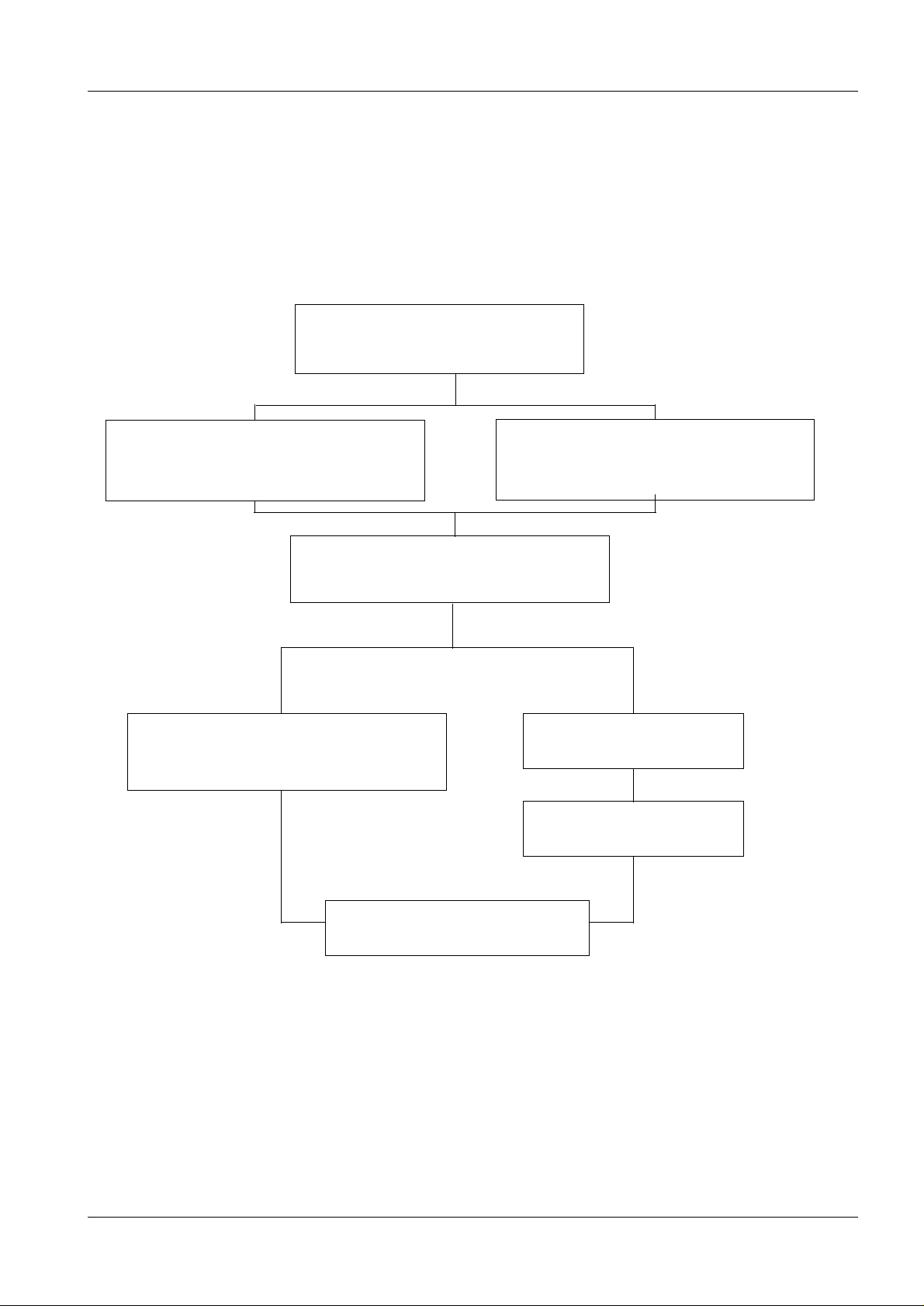
The configuration of the Mammomat installation is dependent on the customer’s choice.
Up to twelve various combinations are possible as shown below:
MAMMOMAT 1000 1
Mammomat 1000 - Basic unit
1 - 1
Molybdenum anode X-ray tube
assembly with filter Mo 0.03
Fixed object-table arm
("Wing 2" no counterweight)
Generator with integrated
control panel and radiation shield
Molybdenum anode X-ray tube
assembly with filter disc
Mo 0.03/Rh 0.025
Separate generator
Separate control console
Free-standing radiation shield
Fig. 1
Siemens-Elema AB Register 3 SPB7-230.033.09 Page 1 of 6 M1000/3000/3000 Nova
Solna, Sweden Rev. 05 06.01 SPS-UD Installation and Start-Up
Page 10
1 - 2 Prerequisites
NOTICE
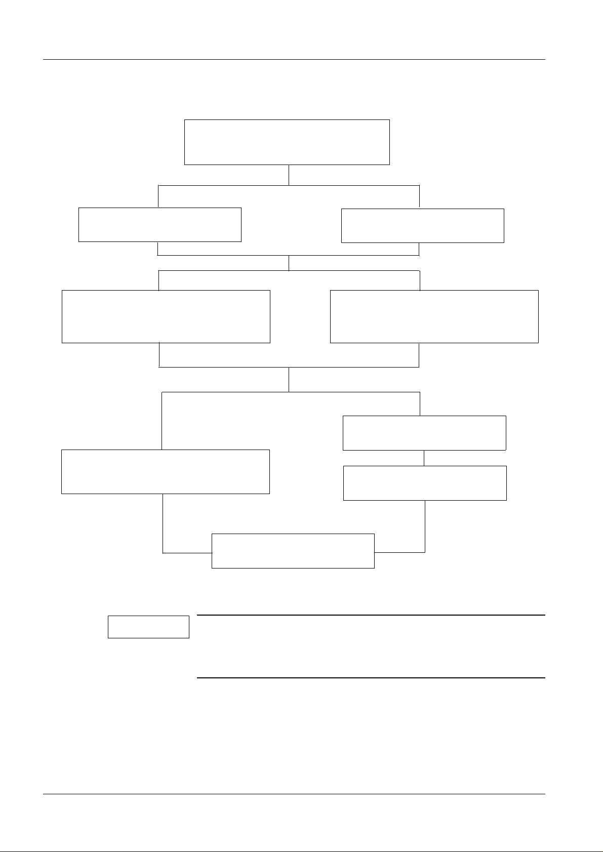
MAMMOMAT 3000/3000 Nova 1
Mammomat 3000/3000 Nova - Basic
Pivoting object-table arm
("Wing 1"+ "Wing 2")
Molybdenum/tungsten anode X-ray
tube assembly with filter disc
Mo 0.03/Rh 0.025/Rh 0.050
Generator with integrated
control panel and radiation shield
Fixed object-table arm
("Wing 1" + counterweight)
Molybdenum anode X-ray tube
assembly with filter disc
Mo 0.03/Rh 0.025
Separate generator
Separate control console
Free-standing radiation shield
Fig. 2
A P40 MoW tube will be delivered irrespective of whether the customer has chosen the molybdenum/tungsten anode X-ray tube or
the molybdenum anode X-ray tube. In the last case, the tungsten
anode is deselected by the software.
Unless otherwise stated, these instruct ions describe the stand with pivoted object-table
arm and generator with integrated radiation shield and control panel.
Depending on the installation configurat ion, some points may be omitted.
M1000/3000/3000 Nova Register 3 SPB7-230.033.09 Page 2 of 6 Siemens-Elema AB
Installation and Start-Up Rev. 05 06.01 SPS-UD Solna, Sweden
Page 11
Prerequisites 1 - 3
NOTICE
WARNING
NOTICE
Meters and appliances, tools 1
Meters and appliances required 1
Calibrated instruments are required.
• Power Line Impedance Meter.
• Protective g round-wire tester.
• Oscilloscope, e. g TEKTRONIX 314.
• Digital multimeter (Fluke type 8060A, part no. 97 02 101 Y4290 or Fl uke type 87, part no.
97 03 976 Y4290).
• Sensitometer.
• Densitometer e.g PDA 81.
• Service PC (e.g. Siemens Nixdorf PCD3-NSX/20 or similar) with connecti ng cable (PC-
Generator), part no. 99 00 440 RE99 9.
• Normi 7 test body (prov ided by the customer) or SIB phantom Type 42 001 (PTW or
INAK).
• Centering cross, pa rt no. 96 60 051 RE 999.
• AEC calibration pl exi (part no. 65 61 240), also called Plexi , comprising:
- Three plates, 2 cm (part no. 65 61 232)
- One plate, 1 cm (part no. 65 61 224)
For safety reasons, the existing protective ground conductor in
the power cord must under no circumstances be disconnected
when operating the oscilloscope. For those measurements, in
which any resulting ground loop may falsify the measuring result,
use the differential amplifier (difference measurement).
Tools required 1
• Standard installa tion tool kit.
• Torque wrench for bolt ing the stand/generator to the f loor (optional).
• Electrical sc rewdriver with adjustable torque is r ecommended.
• Calculator
Checks and/or adjustments, which must be made with X-ray
radiation switched on, are marked with the warning symbol:
Siemens-Elema AB Register 3 SPB7-230.033.09 Page 3 of 6 M1000/3000/3000 Nova
Solna, Sweden Rev. 05 06.01 SPS-UD Installation and Start-Up
Page 12

1 - 4 Prerequisites
NOTICE
Important notes on start-up 1
The MAMMOMAT is adjusted, programmed and tested in the factory, leaving the adapta-
tion to the on-site mains vol tage, adjust ment of t he AEC and t he funct ional tests t o be performed.
When the measurements to be made (kV, mAs, etc.) are within the tole rances stated in
these instructions, th is confirms that the settings made in the factory have not changed
and the equipment is fully serviceable.
The measured values marked with
entered in the "start-up" column in the test certificate provided.
The service PC is required only for programming according to:
? in Chapter 10 "Checks with high voltage" shall be
• Chapter 10 "Checks with h igh voltage"
• Chapter 11 "Calibrat ing and adjusting the AEC"
• Chapter 12 "Testing"
• Chapter 13 "Further programming"
• Chapter 19 "Final procedur es"
Description of the Service-PC syntax is found in Chapter 21 "Appendix".
If the genera t o r is switched off with th e Service PC conn e c te d ,
wait approximately 5 s before switching it on again.
Checking and recording for the area of application of the X-ray decree (§16 Germany)
In the area of application of the X-ray decree, an acceptance test certificate is supplied,
with most of the data filled in by the factory.
1
Only:
• the cut-off dose
• the resolution of th e film/screen systems used
• the output values of the constancy test
must be determined by the owner of the equipment and recorded in the acceptance test
certificate. Furthermore, the front page of the acceptance test certificate must also be
completed with the operator´s data.
M1000/3000/3000 Nova Register 3 SPB7-230.033.09 Page 4 of 6 Siemens-Elema AB
Installation and Start-Up Rev. 05 06.01 SPS-UD Solna, Sweden
Page 13

Prerequisites 1 - 5
Checking and recording for the DHHS area of application 1
In the area of application of the DHHS regulations, maintenance measurements must be
made according to the "DHHS Maintenance Instru ctions" SPB7-230.662.03 .04.02 and the
"DHHS Supplements to the instructions for use" SPB7-230.661.02.03.02.
Sections 1
• Required labels.
• Radiation ON indicators .
• Manual termination of exposure.
• Checking the maximum adjusta ble mAs.
• Filters in beam limi ting device (BLD).
• Reproducibility.
• kVp-accuracy.
• mAs-accuracy.
• Automatic exposure control (AEC).
• Coincidence of radi ation field/image receptor.
• Alignment of light f ield/X-ray field.
• Illuminance of light localizer (light field).
• Shut-down of motor-drive n compression movement.
The result must be recorded in "DHHS Measurement certifi cates"
SPB7-230.663.03.03.02.
Some of the values to be determined can be taken from the acceptance test certificate.
The radiation-field limi tation is set at the fac tory and recor ded in the a cceptance test certif-
icate.
If the measurements to be made concerning the radiation- fiel d limitati on are withi n the to l-
erances stated in these instructions, this confirms that the settings made at the facto ry
have not changed.
Note on delivery state 1
The MAMMOMAT has been tested and adjusted at the factory, and should therefore be
ready for operation after completion o f the i nstallation.
The equipment is set to 400 V, 2-phase, on deli very.
Siemens-Elema AB Register 3 SPB7-230.033.09 Page 5 of 6 M1000/3000/3000 Nova
Solna, Sweden Rev. 05 06.01 SPS-UD Installation and Start-Up
Page 14

1 - 6 Prerequisites
This page intentionally left blank.
M1000/3000/3000 Nova Register 3 SPB7-230.033.09 Page 6 of 6 Siemens-Elema AB
Installation and Start-Up Rev. 05 06.01 SPS-UD Solna, Sweden
Page 15
Protective measures 2
WARNING
WARNING
CAUTION
e
WARNING
Protective measures 2
It is very important that any intervention in the equipment will start with disconnecting it
from the power supply with the main circuit-breaker. Before removing or inserting any of
the printed circuit board, switch of the equipment. To prevent accidental triggering of high
voltage and radiation, set the switch S2 (SS) on p.c. board D702 to "OFF" (lower pos itio n,
no triggering of the SS relay).
If the system is only switched off at the control panel or with
S2/D711, line voltage will still be present at the generator line
connection, line filter Z1, Z2, transformer T1, transformer T10 and
p.c. board D711 (see wiring diagram).
After shut-down of the system, there may still be 380 V DC
present on the intermediate circuit. This will be indi cated by LED
V24 on p.c. board D710. The voltage will drop to less than 30 V
within about 3 minutes, the LED goes out at about 30 V.
2 - 1
The p.c. boards contain electrostatic highly sensitive components
requiring particular care in the ir handling (ground before making
contact and place only on a conductive surface).
The edges of the metal curtain of the stand are very sharp and
may cause severe injury. Apply the protective strips as mentioned
in section Protective Measures after removing the covers from th
the stand. Remove the protective strips only when the covers are
to be mounted or when vertical adjustment of the swivel-arm
system is necessary.
Siemens-Elema AB Register 3 SPB7-230.033.09 Page 1 of 2 M1000/3000/3000 Nova
Solna, Sweden Rev. 05 06.01 SPS-UD Installation and Start-Up
Page 16

2 - 2 Protective measures
Delay times between two exposures 2
Delay times listed below must be followed in order to prevent the tube from overheating.
Exposure mAs value Delay time between two exposures (seconds)
max 100 min 15
max 200 min 30
max 300 min 45
max 400 min 60
max 500 min 75
M1000/3000/3000 Nova Register 3 SPB7-230.033.09 Page 2 of 2 Siemens-Elema AB
Installation and Start-Up Rev. 05 06.01 SPS-UD Solna, Sweden
Page 17

Preparatory wor k 3
CAUTION
General 3
Scope of delivery 3
The MAMMOMAT is normal ly pac ked in o ne cr ate and one ca rdboar d bo x (the number of
packages is dependent on the customer’s choice, however):
Crate (length 2140 mm, width 800 mm, height 1375 mm)
The crate contains:
• Compression plate
• Stand with X-ray tube as sembly and base plate
• Object table 18 cm x 24 cm (Bucky)
• External diaphragm
• Cover panels
• Installati on material
• Optional: Stanchions f or the lead-glass pane (radiati on shield)
3 - 1
• Cable ducts
• Technical documents
Cardboard box (lenght 1210 mm, width 820 mm, height 700 mm)
The cardboard box contains:
• Generator with high- voltage generator and base plate.
• Optional: Lead-glass pane
• Optional: Separate control console
Further accessories are packed in a separate cardboard box.
Unpacking 3
As a general rule, the directional marks on the crates should be observed during transport, storage and unpacking.
The stand crate is bolted together, while the cardboard box is secured with plastic straps.
Wear safety footwear!
Siemens-Elema AB Register 3 SPB7-230.033.09 Page 1 of 8 M1000/3000/3000 Nova
Solna, Sweden Rev. 05 06.01 SPS-UD Installation and Start-Up
Page 18
3 - 2 Preparatory work
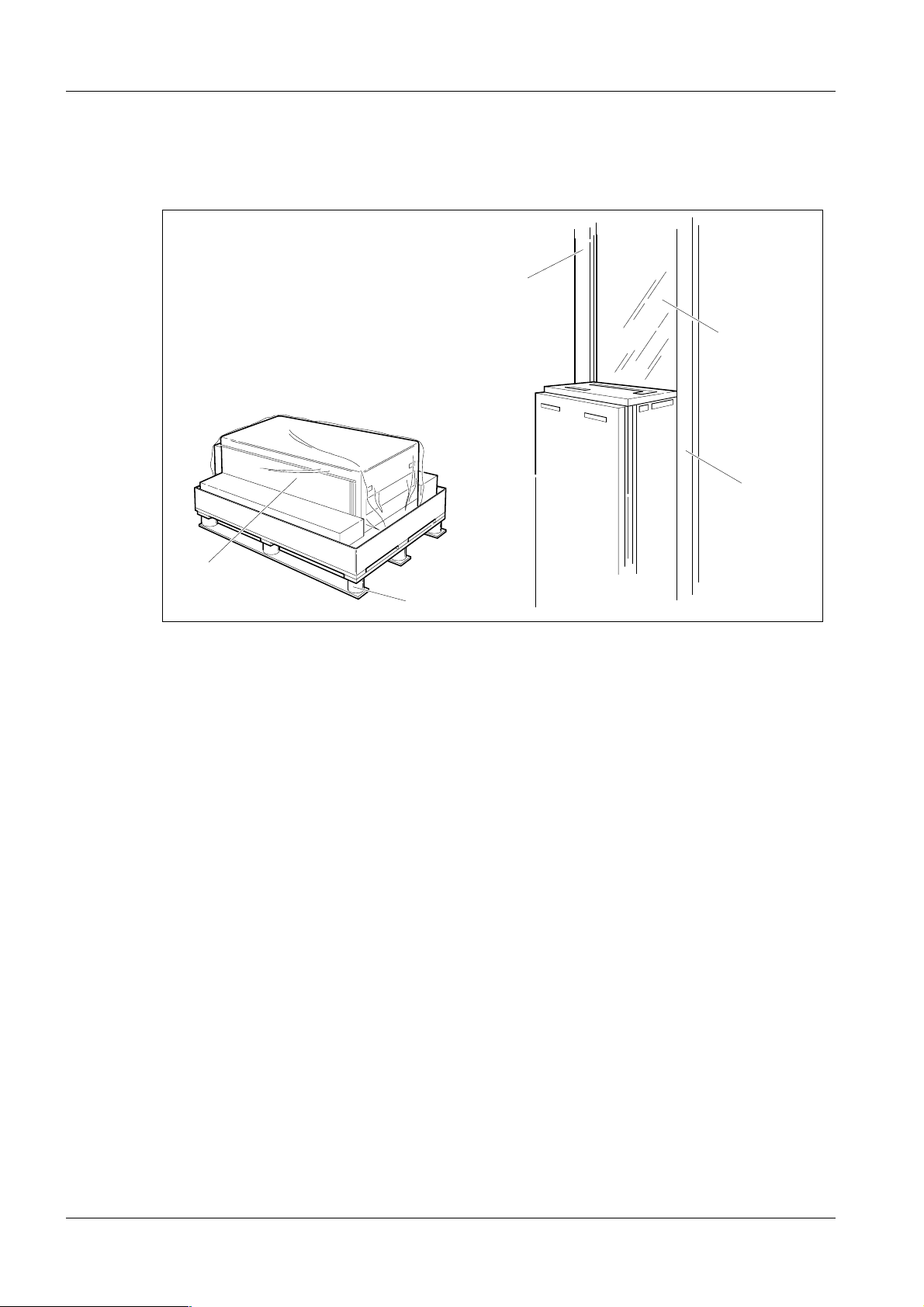
Unpacking the stand 3
1
3
Fig. 1 Unpacking the stand
1
2
5
2
4
6
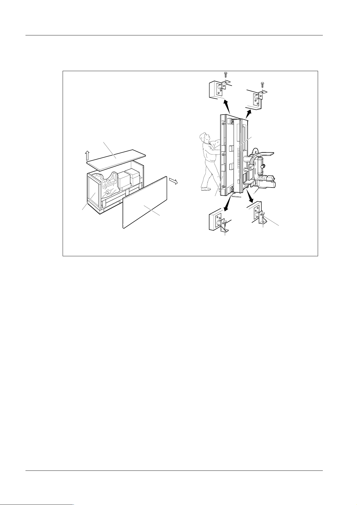
Unpacking
1. Open the stand crate by removing the top (1) and then the s ide wall (2).
2. Take out all enclosed packages (accessor ies, installation materia l, cover panels
etc.) from the crate.
MAM00167
3. Remove the wooden supports.
4. Remove the remaining walls (3).
5. Upend the stand (4), with pallet (5) (two persons are required).
6. Loosen the four bolts (6) and remove the pa llet (5).
M1000/3000/3000 Nova Register 3 SPB7-230.033.09 Page 2 of 8 Siemens-Elema AB
Installation and Start-Up Rev. 05 06.01 SPS-UD Solna, Sweden
Page 19
Preparatory work 3 - 3
NOTICE
Removing the transport safeguards 3
Removing the swivel-arm system transport safeguard 3
1
2
3
MAM00081
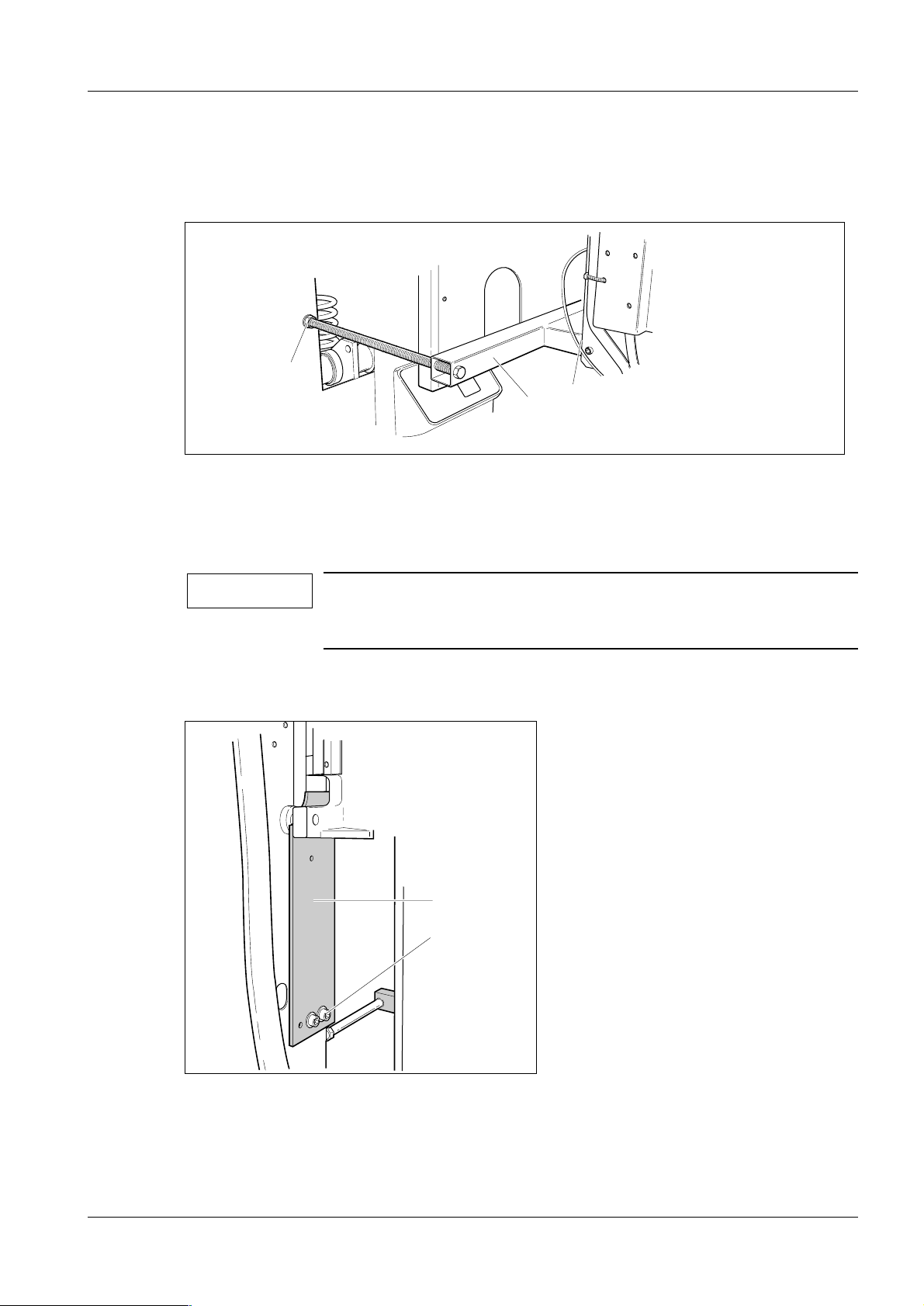
Fig. 2 Swivel-arm system transport safeguard
1. Loosen the transport safeguard nuts ( 1/Fig. 2) and remove the tube head screws
(2/Fig. 2).
2. Push the red transport safeguard (3/Fi g. 2) inwards, away from the tube head.
Removal of the swivel-arm system transport safeguard is done
after the equipment has been powered up, see further section
"Attaching the swivel-arm covers" on page 7 - 1.
Transport safeguard for the lifting carriage 3
2
1
MAM00082
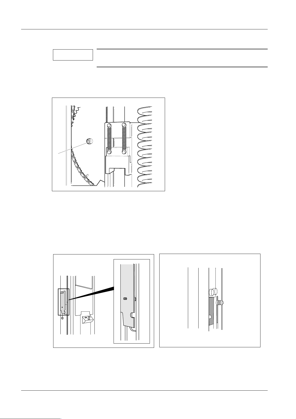
Fig. 3 Transport safeguard for the lifting carriage
1. Loosen the two screws (1/Fig. 3) and remove the red transport safegu ard (2/F ig.
3). Reinsert screws (1/Fig. 3), they might be needed for service purposes.
Siemens-Elema AB Register 3 SPB7-230.033.09 Page 3 of 8 M1000/3000/3000 Nova
Solna, Sweden Rev. 05 06.01 SPS-UD Installation and Start-Up
Page 20
3 - 4 Preparatory work
NOTICE
MAM00312
The lifting carriage transport safeguard shall be kept for service
purposes (Fig. 5).
2. Cut and remove the cable tie securing the balancing spring duri ng transport.
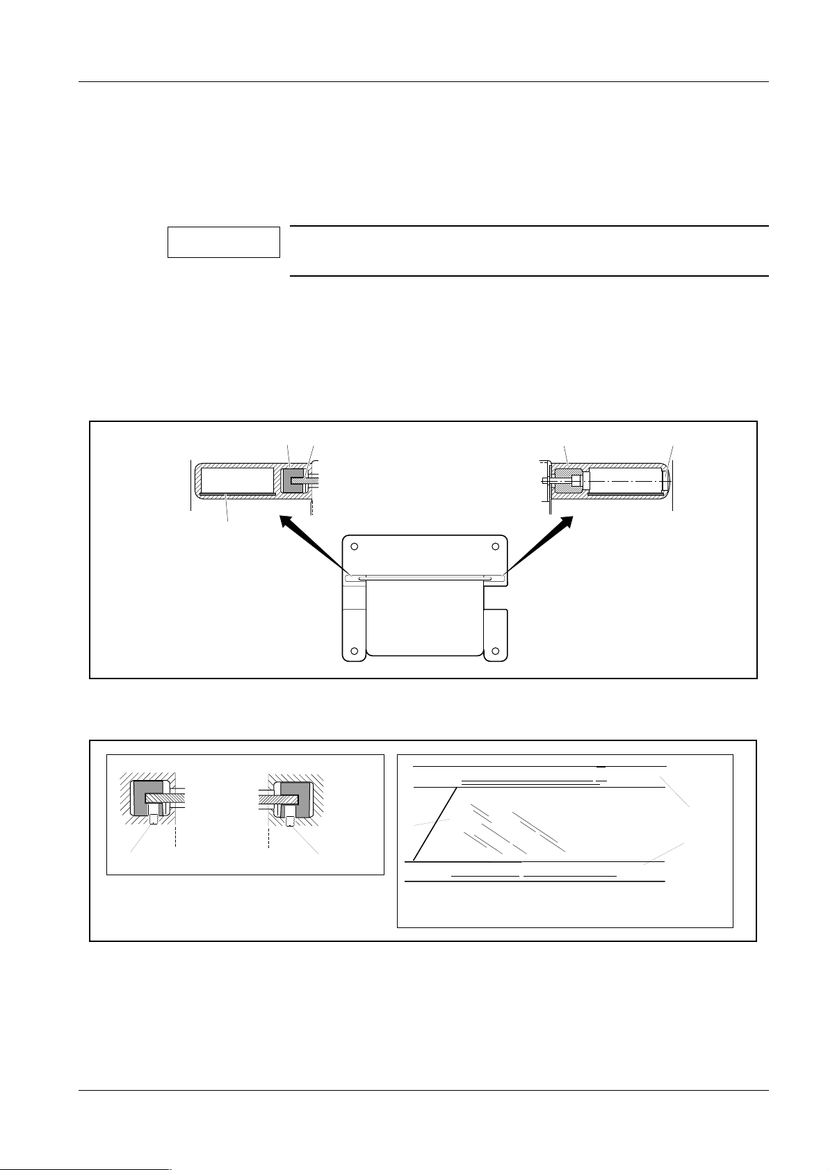
Transport safeguard for the rotary motion 3
1
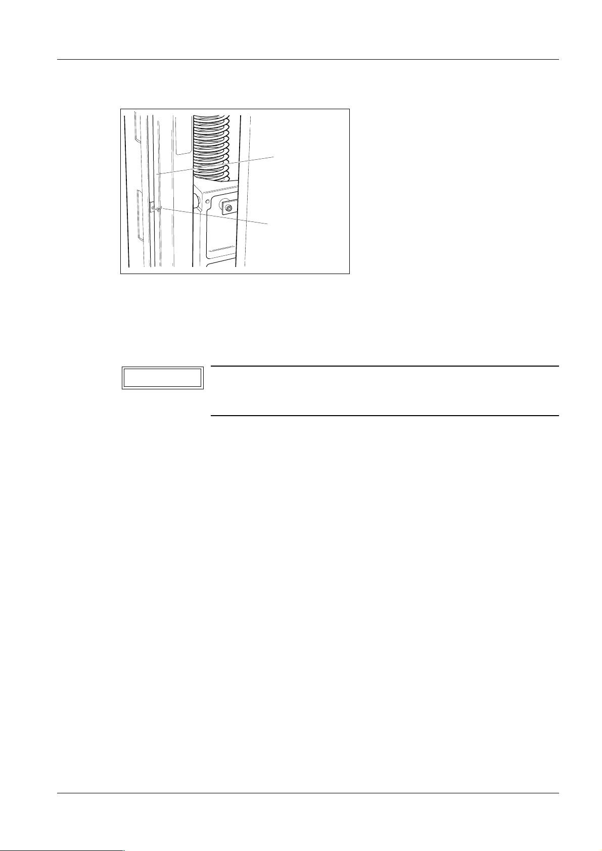
MAM00083
Fig. 4 Transport safeguard for the rotary motion
1. Remove the transport safeguard screw (1/ Fig. 4) with spacer to enable rotary
motion.
The screw and the spacer should be kept for the mo unting of the lifting carriage
transport safeguard.
2. Mount the red lifting carriage t ransport safeguard with screw and spacer
(1/Fig. 4) on the left hand side of the stand, see Fig. 5. Inse rt the screw through the
slot from the inside of the sta nd, see Fig. 6
MAM00314
MAM00313
Fig. 5 Transport safeguard mounted on the stand Fig. 6 Screw and spacer inserted from the inside of the
stand
3. Tighten the screw. Make sure that the transport safeguard is parallell to the
stand.
M1000/3000/3000 Nova Register 3 SPB7-230.033.09 Page 4 of 8 Siemens-Elema AB
Installation and Start-Up Rev. 05 06.01 SPS-UD Solna, Sweden
Page 21
Preparatory work 3 - 5
CAUTION
Protective strips for the metal curtain 3
1
2
MAM00084
Fig. 7 Protective strips for th e metal curtain
The edges of the metal curtain are very sharp and are therefore provided with protective
strips (1) on delivery. These strips must always be applied onto the edges of the metal
curtain during service and maintenance work.
The protective strips must be removed from the metal curtain
before any vertical adjustment of the swivel-arm system is
performed.
Holders (2) for stori ng the protective strips when not in use, are provi ded on both sides of
the curtain, see Fig. 7.
Siemens-Elema AB Register 3 SPB7-230.033.09 Page 5 of 8 M1000/3000/3000 Nova
Solna, Sweden Rev. 05 06.01 SPS-UD Installation and Start-Up
Page 22
3 - 6 Preparatory work
Unpacking the generator and mounting the radiation shield (optional)
1
3
3
4
3
2
MAM00085
Fig. 8 Unpacking the generator
1. Open the cardboard box by cutting the plas tic straps.
2. Lift out the lead-glass and put it away in a safe place.
3. Remove the protective cover from the generat or.
4. Upend the generator (1/Fig. 8) and lift i t off the pallet (2/Fig. 8) ( two persons are
required).
M1000/3000/3000 Nova Register 3 SPB7-230.033.09 Page 6 of 8 Siemens-Elema AB
Installation and Start-Up Rev. 05 06.01 SPS-UD Solna, Sweden
Page 23
Preparatory work 3 - 7
NOTICE
➪ Optional:
5. Insert sheet-metal strip ( 5/Fig. 9) (additional radiatio n protection) into both
stanchions.
6. Fit the lead-glass (4/Fig . 9) into both vibration absorbi ng strips (6/Fig. 9) and fix it
softly by screws (1/Fig. 10).
The screws must be mounted before the lead-glass is inserted in
the stanchions.
7. Fit the lead-glass (2/Fig. 10) into the groove of one of the stanch ions (3 /Fig. 10)
and keep it in position while mounti ng the other stanchion (3 /Fig. 10).
8. Mount the stanchions and lead-glass unit wi th 6 screws onto the generator (3, 4 /
Fig. 8) (two persons are required ).
9. Cover the holes with plastic caps (7/F ig. 9).
6
5
Fig. 9 Mounting the radiation shield
3
74
MAM00086
3
2
1
1
MAM00630
3
MAM00633
Fig. 10
Siemens-Elema AB Register 3 SPB7-230.033.09 Page 7 of 8 M1000/3000/3000 Nova
Solna, Sweden Rev. 05 06.01 SPS-UD Installation and Start-Up
Page 24

3 - 8 Preparatory work
This page intentionally left blank.
M1000/3000/3000 Nova Register 3 SPB7-230.033.09 Page 8 of 8 Siemens-Elema AB
Installation and Start-Up Rev. 05 06.01 SPS-UD Solna, Sweden
Page 25
Installing the generator and the stand 4
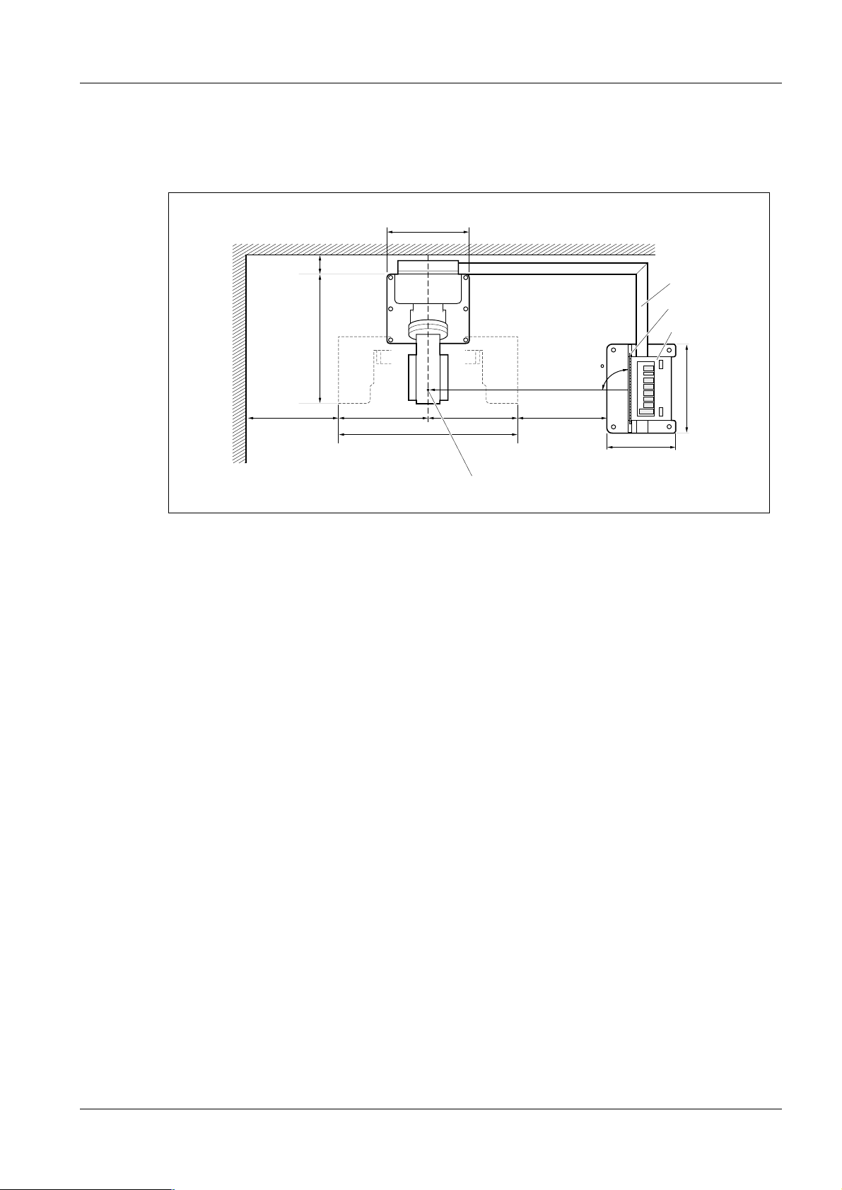
Arranging the components 4
Position the stand and the generator in accordance wi th inst alla ti on plan and Fi g. 1 below.
640
4 - 1
700
Fig. 1 Installation, top view
180
1091
700 700
1400
4
90
700
540
1
2
3
708
MAM00503
Cable duct (1) and generator (3) with radiation shiel d (2) can be installed opt iona lly to the
left or to the right of the the stand. The cables can also be lai d underfloor. Maximum cable
length between stand and generator is approximately 3.5 m.
Radiation shield (2) at right angles to the swivel-arm system and centered to the focus
mark (4) on the tube-head cover according to Fig. 1.
Recommended minimum distance to wall and generator base plate respectively is
700 mm (shorter distances may be used at the customer´s desire, if in compliance with
local regulations).
For the installation of the cable duct, a minimum distance of 180 mm between wall and
stands is required.
Notes on installations with separate generat or and separate control cons ole
- The separate generator can be i nstalled in any suitable place. The maximum distance
of 3.5 m (maximum cable length) to the stand must be maintained, however. If
separately installed, the genera tor must be bolted to the floor alter natively be attached
to the wall by means of wall brackets, see fu rther Chapter 20 "Bolting the stand/
generator to the floor".
- The separate control consol e can be installed in a suitable pla ce (wall-mounted or
mounted on a table, for example in an adjacen t room with radiation-proof window), or
be mounted onto the free-standing radiation shield (option). The connect ion cable to
the generator measures 10 m.
4
Siemens-Elema AB Register 3 SPB7-230.033.09 Page 1 of 6 M1000/3000/3000 Nova
Solna, Sweden Rev. 05 06.01 SPS-UD Installation and Start-Up
Page 26
4 - 2 Installing the generator and the stand
NOTICE
Free-standing radiation shield (option) 4
For the installation of the free-standing radiation shield, please refer to separate instructions enclosed with the radiation shield.
Removing the generator cover 4
1. Pry loose the plastic strip (1) and remove the sixteen screws (2), eight on eac h
side.
Pay special attention to the contact washers (there are four contact washers on either side). They are needed again when reassembling the front cover to establish protective ground
connection and to fulfil EMC (Electro Magnetic Compatibility)
requirements.
2. Remove the front cover (3) from the gener ator.
3
Fig. 2 Removing the generator cover
2
MAM00091
1
M1000/3000/3000 Nova Register 3 SPB7-230.033.09 Page 2 of 6 Siemens-Elema AB
Installation and Start-Up Rev. 05 06.01 SPS-UD Solna, Sweden
Page 27
Installing the generator and the stand 4 - 3
NOTICE
Installing the cable ducts 4
1. Position the cable ducts (1) to the st and and the generator respectively.
2. Leave sufficient space, approx 10 mm between the cable ducts (1) and the base
plate of the stand (3) to allow for t he mounting of the cable outlet cover (4) .
3. Check that the cable duct (1) is sl ightly overlapped by the cable outlet cover (4).
4
3
Fig. 3 Installing the cable ducts (top view)
1
1
10 mm
6
7
1. Mark the outlines of the cable duct s (1) on the floor.
2. Cut the bottom of the cable ducts (6) and the cable duct cover (5) to proper lengt h.
Fig. 3 shows a right-angled installation of the cable ducts. If t he
generator is to be i nstalled a t an other angle to t he stand, you just
have to cut the cable ducts correspondingly.
5
MAM00089
3. Fasten the bottom plate of the cable duc ts (6) to the floor according to marki ng,
using double-sided adhesive tape.
4. At the generator, cover the cable entry not used with the enclosed cover pl ate (7).
Installations with separate control console 4
For the connection cable separate control console – gener ator, additional cable ducts are
required, unless the cables are to be laid underfloor.
Siemens-Elema AB Register 3 SPB7-230.033.09 Page 3 of 6 M1000/3000/3000 Nova
Solna, Sweden Rev. 05 06.01 SPS-UD Installation and Start-Up
Page 28
4 - 4 Installing the generator and the stand
NOTICE
Laying the cable harness 4
Remove the transport safeguards which consist of cable ties
(four around the cable harness and one at the end of each
shielded cable).
1. Separate the cable harness.
2. Lay the stand cable harne ss in the cable duct, as shown in Fig. 4, all the way to the
generator.
3. Fit the cable duct covers (6) ont o the cable ducts.
1
2
3
4
6
1
2
Fig. 4 Laying the cable harness
The cable harness consists of four sh ielded cables, see Fig. 4.
Pos in Fig. 4 Description
1 High voltage cable H1
2 AEC signal cables X10 and X11
Unit control cable X1
Power supply cable X14
MAM00092
5
MAM00215
4
3
3 Anode rotation cable X9
Filament cable X8
4 Mains supply cables L1, L2
Protective ground
5 Decompression-button cable (only with separate control console)
M1000/3000/3000 Nova Register 3 SPB7-230.033.09 Page 4 of 6 Siemens-Elema AB
Installation and Start-Up Rev. 05 06.01 SPS-UD Solna, Sweden
Page 29
Installing the generator and the stand 4 - 5
Installations with separate control console 4
Lay the connecting cable from the control console in additional cable ducts, alternatively
underfloor, to the free cable entry of the generator, see further section Chapter 5 "Cable
connections" on page 5 - 8.
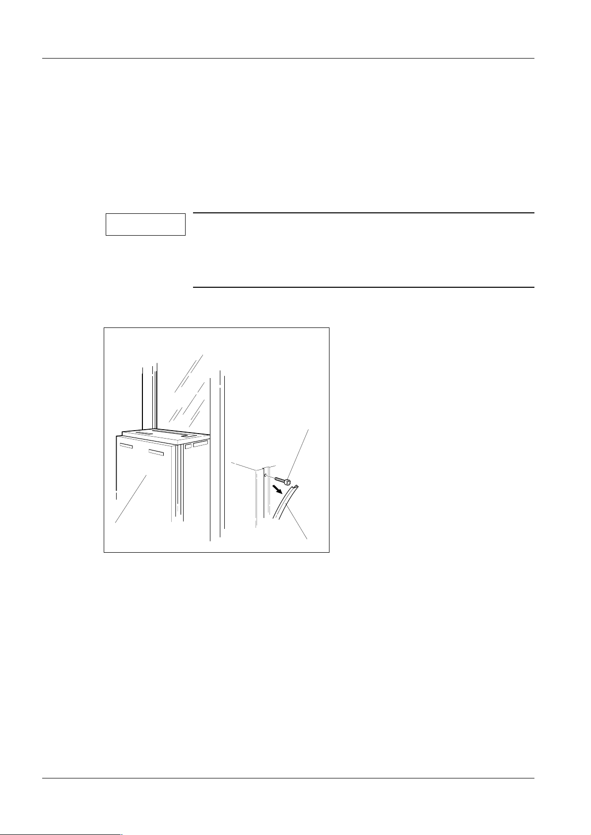
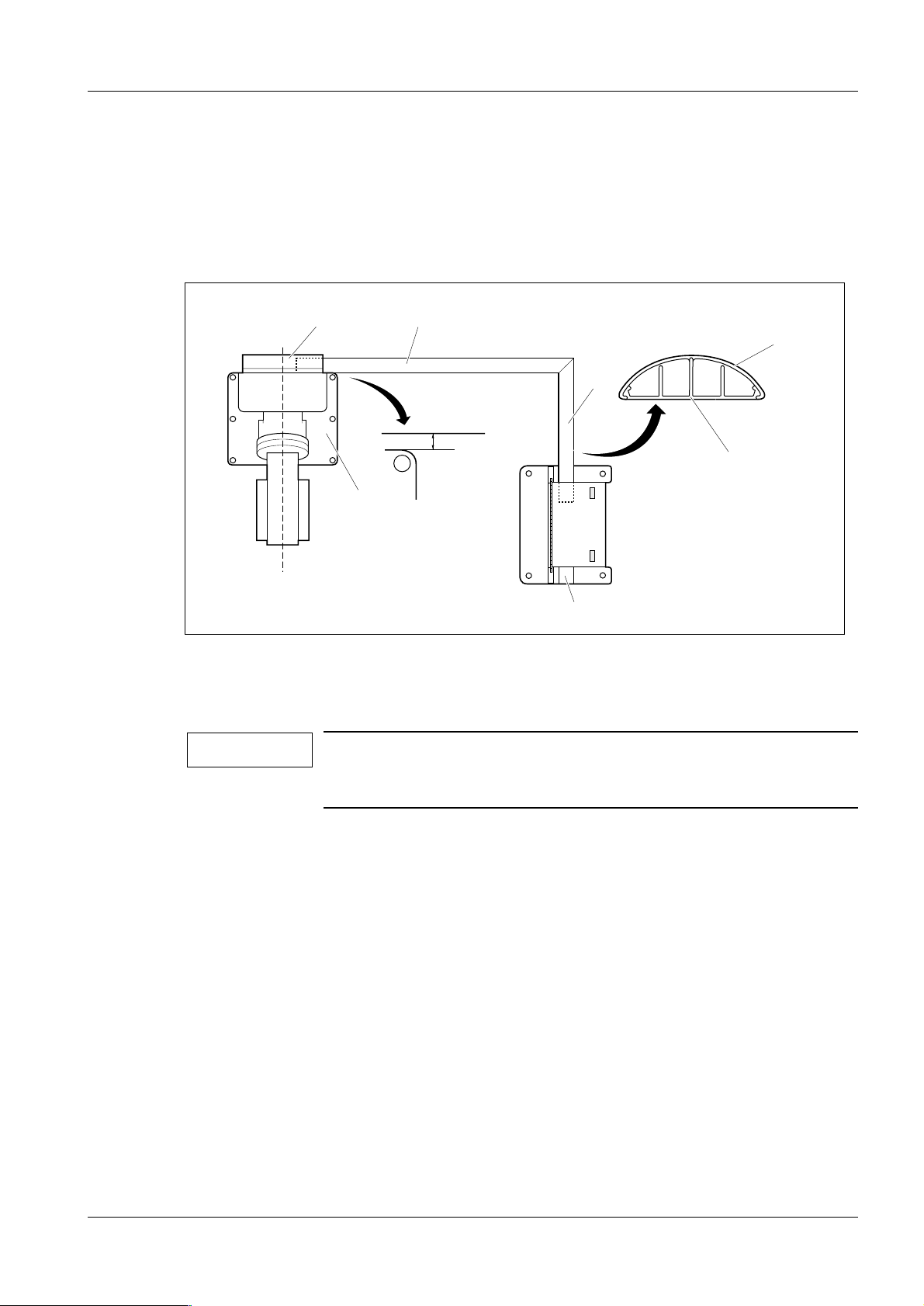
The separate control console can be wall-mounted – horizontally o r vert ic ally as shown in
Fig. 5 below – or be mounted on a table, either in the examination room or in an adjacent
room with radiation-proof window. It is important tha t the control console be place d so that
the operator has good view of the patient from the control console.
Ensure that the control console is attached to the wall with a dequate saf ety margins. Dowels and screws are not supplied. Pleas e obtain th ese lo cally and ensure t hat they ar e suitable for the material used in the wall. The separate control console has a weight of 4 kg.
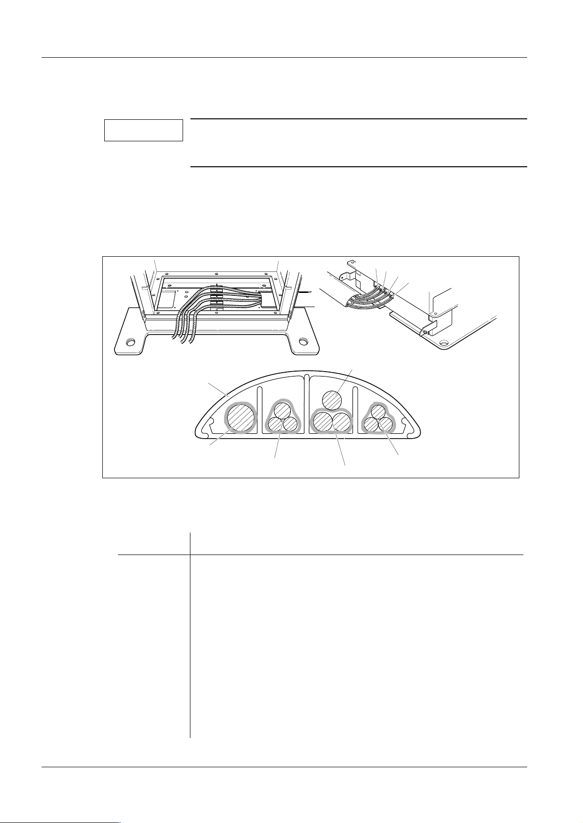
There are two cable outlets on the separate control console; one at the back and one on
the underside. On delivery, the cable is led through the outlet at the back of the control
console. For wall-mounted contro l console, the cable shall be led t hrough the outl et on the
underside.
If the control console is to be mounted on a table, the minimum/maximum length of the
screws penetrating into the control console must be observed, see Fig. 7 below.
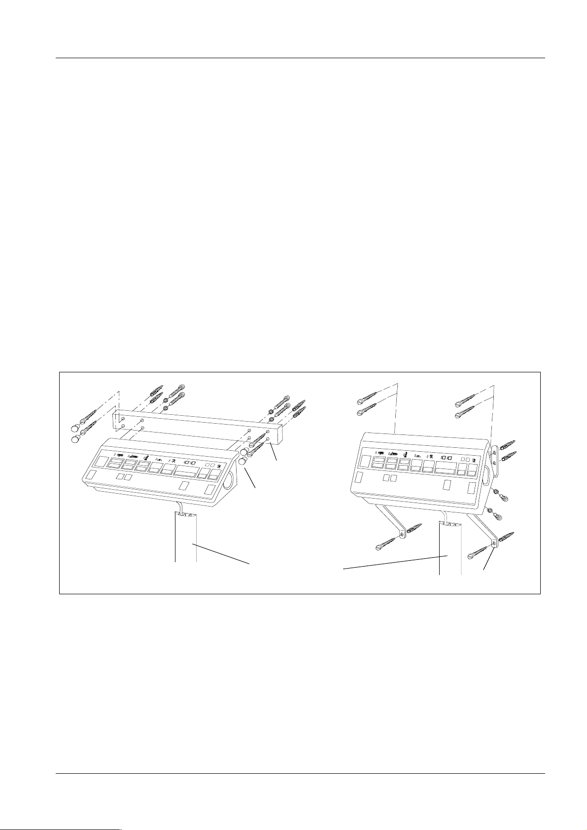
The control console can als o be mounted o n t he free- standin g ra diat ion shi eld ( option) as
shown in Fig. 6 below, see separate instructions enclosed with the radiation shield.
MAM00168
Horizonta l mounting
Fig. 5 Wall-mounted control console
∅ 6.5 mm
Plastic cap
Wall-mounted cable duct
is recommended
MAM00169
∅ 6.5 mm
Vertical mounting
Siemens-Elema AB Register 3 SPB7-230.033.09 Page 5 of 6 M1000/3000/3000 Nova
Solna, Sweden Rev. 05 06.01 SPS-UD Installation and Start-Up
Page 30
4 - 6 Installing the generator and the stand
NOTICE
NOTICE
MAM00171
<
min. 10 mm –
max. 30 mm
<
Table top
MAM00170
Fig. 6 Control console on free-standing radiation shield
(option)
Welded nut
M6
Fig. 7 Control console mounted on table
Aligning the stand 4
1. Align the stand vertically by means of the levelling screws (1/Fig. 8) .
For adjustment of the levelli ng screws, use a ratchet spanner 1/2" with ex tension
(without socket).
It is important that all six screws bear against the fl oor to ensure
optimum stability of the stand.
2. Cover the levelling screws with the c over discs supplied.
1
MAM00090
Fig. 8 Levelling screws
If bolting to the floor is required, please refer to Chapter 20 "Bolting the stand/generator to the floor" on page 20 - 1.
M1000/3000/3000 Nova Register 3 SPB7-230.033.09 Page 6 of 6 Siemens-Elema AB
Installation and Start-Up Rev. 05 06.01 SPS-UD Solna, Sweden
Page 31

Cable connections 5
EMC measures 5
The following measures are required to ensur e electr omagneti c compati bili ty of the equi pment.
EMC measures at the cable entry 5
Fitting the hose clamps and ferrite sleeves 5
3cm
5 - 1
Fig. 1 Cables from the stand
1. Lay the cable harness from the stand to the generator and leave approximately
3 cm of the shielding at the U-bracket, see Fig. 1.
Stow away excessive cable lengths as shown in Fig. 2.
MAM00100
Siemens-Elema AB Register 3 SPB7-230.033.09 Page 1 of 14 M1000/3000/3000 Nova
Solna, Sweden Rev. 05 06.01 SPS-UD Installation and Start-Up
Page 32

5 - 2 Cable connections
4
Fig. 2 Ferrite sleeves and hose clamp
3
3
2
2
1
2. Provide each incoming cable wit h a ferrite sleeve (4), except for main s supply
cables L1 and L2 and the ground wire, which shall be laid together in one and the
same ferrite sleeve. Ferri te sleeves are included in the deliver y.
MAM00098
3. Provide each cable with a hose clamp (3). Hose clamps are included in the
delivery.
4. Fold the shield braid (1) backwards over the U-bracket (2) on each cable and
secure with the hose clamp (3).
Note on separate control console and separate generator 5
If the installation includes a separate control console and separ ate generator, please ref er
to page 5 - 8 for information on ho w to inst all the addi tional connecti on cable bet ween t he
control console and the generator.
M1000/3000/3000 Nova Register 3 SPB7-230.033.09 Page 2 of 14 Siemens-Elema AB
Installation and Start-Up Rev. 05 06.01 SPS-UD Solna, Sweden
Page 33

Cable connections 5 - 3
NOTICE
NOTICE
EMC measures on the bottom plate 5
Fitting the cables X1, X8 and X9 onto the bottom plate 5
3
Fig. 3 Bottom plate
4
2
1
1. Fit the bottom plate at the botto m of the generator stand as shown in Fig. 3.
2. Carefully cut away the insulation on c ables X1, X8 and X9 to lay bare the shield
braid (1).
3. Select proper clamps (2) with regar d to the thickness of the cables. Cable clamps
in different sizes are provided on t he bottom plate.
4. Fit the clamp (2) over the shi eld braid and screw tight to ensure satisfactory
contact between shield braid and cl amp.
5. Fasten the bottom plate with four sc rews (3) and contact washers (4).
Cable X9 shall also be clamped to the side wall of the cabinet, if
not already done, see Fig. 7 in this chapter.
MAM00099
Do not remove insulation and do not ground the shields of the
AEC signal cables to X10 and X11.
Siemens-Elema AB Register 3 SPB7-230.033.09 Page 3 of 14 M1000/3000/3000 Nova
Solna, Sweden Rev. 05 06.01 SPS-UD Installation and Start-Up
Page 34

5 - 4 Cable connections
NOTICE
Connecting the stand cable-harness 5
High-voltage connector 5
3
1
2
MAM00161
Fig. 4 High-voltage connector
The high-voltage connector (1) is factory-adjusted for correct fit.
The high-voltage connector shall be inserted wit h silicone oi l, sil icone-rubber ring (2) and silicone- rubber disc (3). Lubricate the si licone-rubber disc and the pins with silicon oil before mounting
the disc. Make sure that there aren’t any air bubbles between the
disc and the connector.
M1000/3000/3000 Nova Register 3 SPB7-230.033.09 Page 4 of 14 Siemens-Elema AB
Installation and Start-Up Rev. 05 06.01 SPS-UD Solna, Sweden
Page 35

Cable connections 5 - 5
Connecting the high-voltage connector 5
3
2
1
Fig. 5 Connecting the high-voltage connector
4
MAM00162
1. Plug in the high-voltage connector (1) at H1.
2. Tighten the sleeve nut (2) by hand .
3. Tighten the stop screws on the sleeve nut.
4. Position the high-voltage cable (3 ) to the right in the generator an d fasten with
cable ties (4).
Siemens-Elema AB Register 3 SPB7-230.033.09 Page 5 of 14 M1000/3000/3000 Nova
Solna, Sweden Rev. 05 06.01 SPS-UD Installation and Start-Up
Page 36

5 - 6 Cable connections
NOTICE
NOTICE
Connecting the cable harness to the generator 5
Required EMC measures are described on page 5 - 1 in this chapter.
2
1
6
5
Fig. 6 Cable harness at the generator
F10 F20
F1
F2
F3
F4
F5
3
4
7
MAM00165
MAM00165
Unit control cable X1 5
1. Connect the unit control cable X1 t o D700 X1 (1).
Filament cable X8 5
1. Connect the filament cable X8 to D700 X8 (2).
Power supply cable X14 5
1. Connect the power supply cable X14 to D711 X14 ( 3).
2. Strain-relieve it on the s ide with a cable tie (4).
AEC signal cable X10 and X11 5
The AEC signal cable consists of two cables laid together as one
cable with two connectors labeled X10 and X11 at the end of the
cable.
1. Connect the AEC signal cable connectors, X10 and X11, to D700 X10 (5) and X11
(6).
M1000/3000/3000 Nova Register 3 SPB7-230.033.09 Page 6 of 14 Siemens-Elema AB
Installation and Start-Up Rev. 05 06.01 SPS-UD Solna, Sweden
Page 37

Cable connections 5 - 7
CAUTION
Rotating anode cable X9 5
2
4
3
1
MAM00163
Fig. 7 Connecting X9 to the generator
1. Connect the rotating anode cable X9 to D711 X9 (1 ).
2. Connect the two blue free wires from connector D711 X9 (1) to capacitor C51 (2).
3. Clamp the cable to the chassis with a cable cl amp (3).
When fitting the cable clamp, ensure satisfactory contact
between shield braid (4) and chassis.
Siemens-Elema AB Register 3 SPB7-230.033.09 Page 7 of 14 M1000/3000/3000 Nova
Solna, Sweden Rev. 05 06.01 SPS-UD Installation and Start-Up
Page 38

5 - 8 Cable connections
NOTICE
MAM001 2
Installations with separate control console and separate generator 5
MAM00166
Connection cable from separate control console
Fig. 8 Connection cable from separate control console
Shielding the cable from the separate control console as
described below is an absolute demand to comply with the EMC
regulations.
1. Lay the connection cable from the separate control console in additional cable
ducts, alternatively under fl oor, t o the f ree cable ent ry of th e generato r, see Fig. 8.
2. Lay the connection cable in a free U-bracke t. Fold the shield braid over the
U-bracket and secure with a hose clamp as shown i n Fig. 9.
MAM00173
Fig. 9 Shielding the control console cable
M1000/3000/3000 Nova Register 3 SPB7-230.033.09 Page 8 of 14 Siemens-Elema AB
Installation and Start-Up Rev. 05 06.01 SPS-UD Solna, Sweden
MAM00172
Page 39

Cable connections 5 - 9
F
3. Shield the control console cabl e to the bottom plate of the generator as shown in
Fig. 10.
4. Provide the cables with ferrite sleev es. Cables X5 and X32 can be laid together in
one ferrite sleeve, X30 and the decompres sion-button cable in another sl eeve
(two extra ferrite sleeves are i ncluded in the delivery). Plug toget her the
decompression button cables. Shield the dec ompression button cable to the
bottom plate, see Fig. 10. Lay the decompressi on button cable in the cable duct,
alter-natively underfloor, t o the stand, see Fig. 4 in Chapter 4 "Instal ling the
generator and the stand".
X5, X32
Ground wire
Fig. 10 Cables from separate control console
X30
Decompression
button cable
5. Connect X5 and X32 to the corresponding sockets on cir cuit board D700, X30 to
connector T3/X30 at the side of the circuit board chassis. Connect the ground wire
to the protective ground termin al below fuse F10, see Fig. 11.
3
F4
F5
MAM00174
Protective
F10 F20
X32 X5 T3/X30
Fig. 11 Connec ting the cables from the separate control console
Siemens-Elema AB Register 3 SPB7-230.033.09 Page 9 of 14 M1000/3000/3000 Nova
Solna, Sweden Rev. 05 06.01 SPS-UD Installation and Start-Up
ground
MAM00164
Page 40

5 - 10 Cable connections
NOTICE
6. Shield the decompression button cable to the stand chassis as shown in Fig. 12.
Connect to terminals 2 and 3 in terminal block X803 on the inside of the stand
chassis, see Fig. 12.
Fig. 12 Connec ting the decompression button cable at the stand
1
Z801
2
1
23
X880
4
X885
MAM00175
Main voltage connection 5
The equipment has been set to 400 V, 2-phase, in the factory (see test certificate).
Adjustment to the line frequency is not needed. If the mains volt age is not 400 V, 2-phase
at the installation site, a reconnection of the mains is necessary.
Should a reconnection for the mains voltage be necessary, this must be done at transformer T10 as well as p.c. board D711 (insertion or removal of fuses and labeling is specified in the wiring diagram, see Line Input page 5-3).
Change the rated voltage labels to the correct voltage (there are two labels on the generator and one on the stand). Labels are included in the installation material.
For more details about changing mains, insertion or removal of
jumpers, fuses, labeling etc., see Wiring Diagram.
M1000/3000/3000 Nova Register 3 SPB7-230.033.09 Page 10 of 14 Siemens-Elema AB
Installation and Start-Up Rev. 05 06.01 SPS-UD Solna, Sweden
Page 41

Cable connections 5 - 11
Connecting the incoming mains to the stand (400 V, 2-phase) 5
400 V 2-phase connection 5
N
3
L1
L2
L
1
2
1
1
4
3
1
Fig. 13 Incom ing mains cable
1. Connect the incoming mains cable (1) to X899 (2) in the stand as shown in Fig. 13
and Fig. 14.
2. Fit plastic tubes (4) on the plat es.
3. Strain-relieve (3) the i ncoming mains cable.
TWO-PHASE
GENERATOR STAND
F10
F20
X881
Incoming mains
208, 230, 240, 277 or 400 VAC
P.ENL1L2L3
X899
MAM00097
MAM00095
Fig. 14 Incoming mains, 2-phase
Siemens-Elema AB Register 3 SPB7-230.033.09 Page 11 of 14 M1000/3000/3000 Nova
Solna, Sweden Rev. 05 06.01 SPS-UD Installation and Start-Up
Page 42

5 - 12 Cable connections
Connecting the mains supply to the generator (400 V, 2-phase) 5
F1
Fig. 15 Mains supply to the generator
F10 F20
F2
F3
F4
F5
2
1
3
MAM00176
1. Check that there is no wire jumper at F2 0 (1) and no brass plug at F5 (2).
Fuses must be inserted into fuse holders F20 an d F5.
2. Connect the mains supply cables between stan d and generator to fuses F10 and
F20 on the generator.
Wire marked L1 to F10 and L2/N to F20.
3. Connect the protective ground wire fr om the stand to the generator (3).
M1000/3000/3000 Nova Register 3 SPB7-230.033.09 Page 12 of 14 Siemens-Elema AB
Installation and Start-Up Rev. 05 06.01 SPS-UD Solna, Sweden
Page 43

Cable connections 5 - 13
CAUTION
NOTICE
Measures for changing from 2-phase to 1-phase connection 5
SINGLE PHASE
GENERATOR STAND
F10
X881
Fig. 16 Incoming mains, 1-phase
Incoming mains
110, 208, 230, 240 or 277 VAC
P.ENL1L2L3
X899
MAM00096
1. Move wire marked N/L2 from X899 L2 to X899 N (stand).
2. Connect incoming phase of the power supply to L1 and the neutral conductor of
the power supply (0 V) to N and fuse F20.
3. Strain-relieve the incomi ng mains cable as shown in Fig. 13.
4. Short circuit F20 (1) and F5 (2) in Fi g. 15 with the jumper and brass plug included
in the service bag.
For single-phase mains connection, make sure that the neutral
conductor of the power supply (0V) is connected to terminal N
and fuse F20.
Connections on transformer T10 must be adapted to the actual
mains voltage, see Wiring Diagram for details.
5. Connect the mains supply cable between stand and generator to fuses F10 and
F20 on the generator. Wire marked L1 to F10 and L2/N t o F20.
Siemens-Elema AB Register 3 SPB7-230.033.09 Page 13 of 14 M1000/3000/3000 Nova
Solna, Sweden Rev. 05 06.01 SPS-UD Installation and Start-Up
Page 44

5 - 14 Cable connections
This page intentionally left blank.
M1000/3000/3000 Nova Register 3 SPB7-230.033.09 Page 14 of 14 Siemens-Elema AB
Installation and Start-Up Rev. 05 06.01 SPS-UD Solna, Sweden
Page 45

Mains connection and power supply 6
Checks before powering up the generator 6
On P.C. board D702:
1. Set switch S1(UZW) to "OFF" (lower posit ion).
2. Set switch S2 (SS) to "OFF" (lower position) .
6 - 1
ZBL
AR
KVE
BRAKE
STATUS
UZW
SS
TEST
V6
V7
V1
V2
V3
V4
V5
VH
NSE1
NSE2
DS
SS
BS
GND
X990
X967
X980
X981
X982
X983
X984
X985
S1
S2
S3
J39
X962
X964
X960
R13
R11
R43
J50
X965
X961
X963
IHREG
MAREG
X966
X968
X969
X702
MAM00106
Fig. 1 P.C. board D702
Measuring the line resistance 6
See Fig. 2.
1. Remove fuses F10 (1) and F20 (2) or, when sin gle-phase supply, fuse F10 (1).
2. Connect line resistance meter to fuse hol ders F10 and F20.
3. Mains supply "ON".
4. Carry out measurement.
5. Mains supply "OFF".
Siemens-Elema AB Register 3 SPB7-230.033.09 Page 1 of 4 M1000/3000/3000 Nova
Solna, Sweden Rev. 05 06.01 SPS-UD Installation and Start-Up
Page 46

6 - 2 Mains connection and power supply
To achieve the full output, the resistance measured must not exceed the following values:
• 0.25 c at 110 V (1-phase)
• 0.45 c at 208 V
• 0.50 c at 230 V
• 0.60 c at 240 V
• 0.65 c at 277 V
• 0.85 c at 400 V (2-phase)
If the above values are exceeded, reduce the generator power in accordance to Chapter
13 "Further programming" in this manual.
Checking the line voltage in the generator 6
1. If not already done, remove fuses F10 (1) and F20 (2) or, when single-phase
supply, fuse F10 (1).
4
5
6
1
2
3
Fig. 2 Line voltage in the generator
2. Mains supply "ON".
3. Measure the voltage at fuse holders F10 ( 1) and F20 (2).
4. Check that the mains voltage agrees with the v oltage plugged on transformer T10
(3) and P.C. board D711 (4), located above li ne filter Z1 (5).
5. Mains supply "OFF".
MAM00177
6. Reinsert fuses F10 (1) and F20 (2).
7. Mains supply "ON" (Do not switch the system on yet).
8. Measure the voltage at transformer T1 (6) terminals 1 and 3, transformer T1 is
located under the line filter Z1 (5). There must be 195 V- 253 V between the
terminals.
9. Measure the voltage at the output of l ine filter Z1 it must lie wit hin 195 V- 264 V.
M1000/3000/3000 Nova Register 3 SPB7-230.033.09 Page 2 of 4 Siemens-Elema AB
Installation and Start-Up Rev. 05 06.01 SPS-UD Solna, Sweden
Page 47

Mains connection and power supply 6 - 3
Checking the supply voltages 6
The correct supply voltages +5 V, +15 V and +24 V have already been tested in the factory. Only a visual check of the function is t herefore needed.
1. System "ON".
2. Check that the following orange dio des are "ON" on p.c. board D704:
V39 (+15 V)
V38 (-15 V)
V41 (+5 V)
V40 (+24 V)
Siemens-Elema AB Register 3 SPB7-230.033.09 Page 3 of 4 M1000/3000/3000 Nova
Solna, Sweden Rev. 05 06.01 SPS-UD Installation and Start-Up
Page 48

6 - 4 Mains connection and power supply
This page intentionally left blank.
M1000/3000/3000 Nova Register 3 SPB7-230.033.09 Page 4 of 4 Siemens-Elema AB
Installation and Start-Up Rev. 05 06.01 SPS-UD Solna, Sweden
Page 49

Attaching the swivel-arm covers 7
Attaching the swivel-arm covers 7
Arranging the swivel-arm system 7
1. Install object table, no co mpression force (swivel-arm system stil l upside down).
2. Remove the protective strips fr om the metal curtain.
3. Run the lifting carriage upwards.
4. Put back the protective strips onto t he metal curtain.
5. Rotate the swivel-arm system t o 0 degrees by pressing one of the switches for
clockwise rotation on the support ing arm.
6. System and mains "OFF".
7. Remove the swivel-arm system transpo rt safeguard, see Chapter 3 "Preparat ory
work".
Connecting the cables to control-button boards and patient handles 7
MAMMOMAT 1000/3000/3000 Nova
4
2
1
3
7 - 1
2
Fig. 1 Connecting the cables
Before installing the side covers, the cables are to be connected.
MAMMOMAT 1000/3000/3000 Nova
1. Connect cables X807 (1) to control-butt on circuit boards D807 (2).
2. Connect ground wires (3) to pati ent handles (4).
1
4
3
MAM00108
Siemens-Elema AB Register 3 SPB7-230.033.09 Page 1 of 2 M1000/3000/3000 Nova
Solna, Sweden Rev. 05 06.01 SPS-UD Installation and Start-Up
Page 50

7 - 2 Attaching the swivel-arm covers
NOTICE
CAUTION
CAUTION
Attaching the side covers 7
Screws in different sizes are included in the delivery.
5
4
Fig. 2 Covers and sign
2
1
1. Mount the side covers (1) with six screws (2) on each side.
Do not forget to fit the sign (3) when mounting the side covers.
Use the two longer screws.
3
MAM00700
Attaching the front cover 7
Because of the risk of damages, the following work must be
carried out with caution. If the covers are exposed to internal
stress cracks might arise.
1. The side covers must be flush at the fr ont. If necessary, loosen the screws and
adjust the side covers.
2. Carefully fit the front cover (4) so that both openings engage with the lugs of the
side covers.
3. Carefully swing the front cover upwar ds and let it snap in position over the s ide
covers.
The front cover must not press against the collimator (risk of
damage).
4. Fasten the front cover to the side covers with two short screws (5).
M1000/3000/3000 Nova Register 3 SPB7-230.033.09 Page 2 of 2 Siemens-Elema AB
Installation and Start-Up Rev. 05 06.01 SPS-UD Solna, Sweden
Page 51

Checking the microprocessors 8
Microprocessors 8
The following LED displays on the processor P.C. boards indicate whether the relevant
microprocessors are operating correctly.
1. Mains and system "ON".
The following conditions must be indi cated after not more than 15 s.
8 - 1
Microprocessors for:
AEC: P.c. board D701
Master: P.c. board D702
P.C. board D711:
• V9 "ON" (line voltage on).
• V13 "OFF" (system stand-by).
• V11 "ON" (system on).
• V16 "ON" (intermediate circuit - filament).
LED displays
Must be off.
Steadily on.
Must be steadily
on or off.
Must be off.
Flashing rapidly.
MAM00649
Siemens-Elema AB Register 3 SPB7-230.033.09 Page 1 of 2 M1000/3000/3000 Nova
Solna, Sweden Rev. 05 06.01 SPS-UD Installation and Start-Up
Page 52

8 - 2 Checking the microprocessors
This page intentionally left blank.
M1000/3000/3000 Nova Register 3 SPB7-230.033.09 Page 2 of 2 Siemens-Elema AB
Installation and Start-Up Rev. 05 06.01 SPS-UD Solna, Sweden
Page 53

Checks without high voltage 9
NOTICE
Checks without high voltage 9
1. System "OFF".
2. On P.C. board D702 set switch S1 (UZW) to "ON" (upper p osition) and switch S2
(SS) to "OFF" (lower position).
3. System "ON".
4. Insert a cassette.
5. Set 27 kV and maximum mAs on the control panel.
The cassette must be removed and reinserted after each
exposure to allow for the next exposure release. This is to avoid
double exposures.
6. Press the exposure buttons on the control panel . The rotating anode s hall start up.
At the end of the time limit, the rotati ng anode is braked.
7. Release the exposure buttons.
9 - 1
8. System "OFF".
Siemens-Elema AB Register 3 SPB7-230.033.09 Page 1 of 2 M1000/3000/3000 Nova
Solna, Sweden Rev. 05 06.01 SPS-UD Installation and Start-Up
Page 54

9 - 2 Checks without high voltage
This page intentionally left blank.
M1000/3000/3000 Nova Register 3 SPB7-230.033.09 Page 2 of 2 Siemens-Elema AB
Installation and Start-Up Rev. 05 06.01 SPS-UD Solna, Sweden
Page 55

Checks with high voltage 10
NOTICE
Preparation 10
This section describes how to check:
• High voltage.
• Tube current.
• mAs va lues.
Check that the high-voltage plug is plugged into H1 and properly
secured.
kV>17
V39
kV>50
V41
WR_AUS
V40
10 - 1
0VA
KVE
KVA
ZBL
0VD
X706
X707
X705
X704
X713
X710
X712
X711
X708
X714
X715
X716
X717
X709
R136
X703
MASOLL
MAIST
IHSOLL
IHIST
UZIST
ISCHWING
KVSOLL
KVIST
BRAKE
Fig. 1 P.C. board D705
1. Set switch S2 (SS) to "ON" (upper position) on P.C. board D702.
2. Remove the jumper and connect the mAs meter to mAs measuring so ckets X3
and X4 on P.C. board D710.
MAM00111
Siemens-Elema AB Register 3 SPB7-230.033.09 Page 1 of 10 M1000/3000/3000 Nova
Solna, Sweden Rev. 05 06.01 SPS-UD Installation and Start-Up
Page 56

10 - 2 Checks with high voltage
NOTICE
NOTICE
WARNING
3. Connect oscilloscope to P.C. board D705 as fol lows:
• Channel 1 to measuring point "KVIST (actual value)" (1 V= 5 kV).
• Channel 2 to measuring point "MAIST (actual value)" (1 V= 40 mA).
• Trigger at measuring point "KVE" (start with high vo ltage "ON"), rising edge.
• Twist the measuring leads and connect their groun ding braids to measuring
point "0 VA".
4. Connect service PC to circuit board D702 usi ng the connection cable.
Switch S3 on circuit board D702 must be set to upper position.
5. Start service program, see Chapter 21 "Append ix".
6. Check the anode menu for correct selecti on (tungsten anode enabled or disabled,
depending on which type of X-ray tube the customer has chosen). See Service
Program Instructions RX B7-230.114.0 1. ... .
It is possible to sel ect tungsten anode, even if the customer does
not have this option. However, the 50
missing.
µm Rh filter will then b e
kV-adjustment 10
Check the kV as follows:
1. Mains voltage and system OFF.
After shut-down of the system, there may be about 380 V d.c.
present on the intermediate circuit. This will be indicated by LED
V24 on PC board D710. The voltage will drop to less than 30 V
within about 3 minutes; the LED goes out at about 30 V.
2. Connect DVM between the lower ends of R72 and R73 (on the left si de of the high
tension plug) on D710 circuit boar d.
3. Mains voltage and system ON.
4. Set 27 kV and maximum mAs on the control panel.
5. Make an exposure and check that the DVM shows +2.700 V +0.010 V. Note the
values in the kV-adjustment prot ocol on page 21 - 3.
M1000/3000/3000 Nova Register 3 SPB7-230.033.09 Page 2 of 10 Siemens-Elema AB
Installation and Start-Up Rev. 05 06.01 SPS-UD Solna, Sweden
Page 57

Checks with high voltage 10 - 3
NOTICE
6. If necessary, adjust R43 on D702 (Fig. 2) and make another exposure. Note the
new values in the kV-adjustment protoc ol.
Decrease
kV
Potentiometer
R43
Fig. 2
Increase
kV
Do not overload the X-ray tube by making too many exposures in a
short time.
R43 does not need to be relocked with locking paint.
7. Mains and system OFF.
8. Disconnect DVM from R72 and R73.
MAM00528
Siemens-Elema AB Register 3 SPB7-230.033.09 Page 3 of 10 M1000/3000/3000 Nova
Solna, Sweden Rev. 05 06.01 SPS-UD Installation and Start-Up
Page 58

10 - 4 Checks with high voltage
NOTICE
Filament 10
1. In <Mainmenu> select <Confi guration> and <Filament>.
Filament
Filament current @ 25 kV
Large focus molly 6500
Large focus tungsten 6500
Small focus molly 6500
Small focus tungsten 6500
<ESC> to exit, <TAB> move to next entry field
1 Help 2 Save 3 45678910Quit
Learn
MAM00657
2. Perform Learn filament for availabl e options.
3. Note the new values in the Test protocol (Fil ament).
Only settings for Mo available for M1000.
M1000/3000/3000 Nova Register 3 SPB7-230.033.09 Page 4 of 10 Siemens-Elema AB
Installation and Start-Up Rev. 05 06.01 SPS-UD Solna, Sweden
Page 59

Checks with high voltage 10 - 5
Checking X-ray tube high voltage, tube current and mAs values 10
1. System "ON".
2. Set the "cassette loaded" switch to "OFF" with the service PC program:
Configuration - Miscellaneous - Cassette loaded check.
3. Trigger test exposures with the f ollowing exposure values and check the k V
values and tube current characterist ic on the oscilloscope (see o scillograms).
The accuracy of the kV is &5% plus &1.5 kV during the first 5 ms of the exposure.
For mA values < 50 mA, the accuracy of the kV is &5% plus &2 kV during the first
5ms.
The tube current must rise quickl y to the set value at the beginning of the exposure and run linearly during the exposure.
The accuracy of the mAs product must be &10%.
4. Replace the jumper previously removed f rom sockets X3 and X4 on P.C. board
D710.
Siemens-Elema AB Register 3 SPB7-230.033.09 Page 5 of 10 M1000/3000/3000 Nova
Solna, Sweden Rev. 05 06.01 SPS-UD Installation and Start-Up
Page 60

10 - 6 Checks with high voltage
NOTICE
NOTE
Oscilloscope diagrams 10
• MAMMOMAT in mAs mode, see Fig. 3 - Fig. 10.
Checks indicated by * shall be disregarded in installations with
filter disc Mo 0.03 / Rh 0.025 (molybdenum rotating anode).
Tube P40 MoW,
MAMMOMAT 3000/3000 Nova
* tungsten anode 0.3
30 kV 20 mAs (P = 4.7 kW)
Tube P40 MoW,
MAMMOMAT 1000/3000/3000 Nova
molybdenum anode 0.3
30 kV 20 mAs (P = 3.75 kW)
?
MAM00179
Fig. 3 Fig. 4
30 kV 1 V/T (1 T <=> 5 kV) 30 kV 1 V/T (1 T <=> 5 kV)
158 mA 1 V/T (1 T <=> 40 mA) 125 mA 1 V/T (1 T <=> 40 mA)
127 ms 20 ms/T 160 ms 20 ms/T
?
MAM00112
Record the measured kV and mAs value in the T est protocol , page
21 - 7.
M1000/3000/3000 Nova Register 3 SPB7-230.033.09 Page 6 of 10 Siemens-Elema AB
Installation and Start-Up Rev. 05 06.01 SPS-UD Solna, Sweden
Page 61

Checks with high voltage 10 - 7
Tube P40 MoW,
MAMMOMAT 3000/3000 Nova
* tungsten anode 0.3
35 kV 100 mAs (P = 4.7 kW)
MAM00180
Fig. 5 Fig. 6
Tube P40 MoW,
MAMMOMAT 1000/3000/3000 Nova
molybdenum anode 0.3
35 kV 100 mAs(P = 3.75 kW)
35 kV 1 V/T (1 T <=> 5 kV) 35 kV 1 V/T (1 T <=> 5 kV)
134 mA 1 V/T (1 T <=> 40 mA) 107 mA 1 V/T (1 T <=> 40 mA)
0.75 s 0.2 s/T 0.93 s 0.2 s/T
MAM00113
25 kV 100 mAs (P = 4.7 kW)
MAM00181
Fig. 7 Fig. 8
25 kV 100 mAs(P = 3.75 kW)
25 kV 1 V/T (1 T <=>5 kV) 25 kV 1 V/T (1 T <=> 5 kV)
188 mA 2 V/T (1 T <=> 80 mA) 150 mA 2 V/T (1 T <=> 80 mA)
0.53 s 0.1 s/T 0.67 s 0.1 s/T
MAM00114
Siemens-Elema AB Register 3 SPB7-230.033.09 Page 7 of 10 M1000/3000/3000 Nova
Solna, Sweden Rev. 05 06.01 SPS-UD Installation and Start-Up
Page 62

10 - 8 Checks with high voltage
NOTICE
NOTICE
Tube P40 MoW,
MAMMOMAT 3000/3000 Nova
* tungsten anode 0.15
30 kV 10 mAs (P = 0.85 kW)
Tube P40 MoW,
MAMMOMAT 1000/3000/3000 Nova
molybdenum anode 0.15
30 kV 10 mAs (P = 0.70 kW)
?
MAM00182
Fig. 9 Fig. 10
30 kV 1 V/T (1 T <=> 5 kV) 30 kV 1 V/T (1 T <=> 5 kV)
28 mA 0.5 V/T (1 T = 20 mA) 23 mA 0.5 V/T (1 T <=> 20 mA)
>>
?
MAM00115
360 ms 50 ms/T 430 ms 100 ms/T
Small focus is selected by attaching a magnification table.
Record the measured kV and mAs value in the test protocol, pa ge
21 - 7.
M1000/3000/3000 Nova Register 3 SPB7-230.033.09 Page 8 of 10 Siemens-Elema AB
Installation and Start-Up Rev. 05 06.01 SPS-UD Solna, Sweden
Page 63

Checks with high voltage 10 - 9
NOTICE
Measurements in AEC mode shall be performed after calibrating
and adjusting the AEC.
Tube P40 MoW,
MAMMOMAT 3000/3000 Nova
* tungsten anode 0.3
30 kV AEC
(P = 4.7 kW)
40 mm plexiglass
MAM00666
Fig. 11 Fig. 12
30 kV 1 V/T (1 T <=> 5 kV) 30 kV 1 V/T (1 T <=> 5 kV)
Tube P40 MoW,
MAMMOMAT 1000/3000/3000 Nova
molybdenum anode 0.3
30 kV
AEC
(P = 3.75 kW)
40 mm plexiglass
MAM00667
158 mA 1 V/T (1 T <=> 40 mA) 125 mA 1 V/T (1 T <=> 40 A)
*) 100 ms/T) *) 100 ms/T
*) total exposure time dependent on programmed sensitivity
Siemens-Elema AB Register 3 SPB7-230.033.09 Page 9 of 10 M1000/3000/3000 Nova
Solna, Sweden Rev. 05 06.01 SPS-UD Installation and Start-Up
Page 64

10 - 10 Checks with high voltage
This page intentionally left blank.
M1000/3000/3000 Nova Register 3 SPB7-230.033.09 Page 10 of 10 Siemens-Elema AB
Installation and Start-Up Rev. 05 06.01 SPS-UD Solna, Sweden
Page 65

Calibrating and adjusting the AEC 11
NOTICE
NOTICE
Check that all object tables do not have AEC grids.
If they have AEC grids remove the grid bars according to
"Installation Instructions object tables" RXB7-120.031.06..., which
is delivered with each object table.
Checking and programming with the service PC 11
Use the service PC to check and program the AEC.
Operation of the service PC is described in Chapter 21 "Appendix".
The AEC is based on correction tables. The tables are optimized for the f ollowing film/
screen combinations.
The tolerances of the AEC are specified for incremental gamma e 5.
Table 1 Correction table identifications
Film Screen Cassette Sensitivity Mo/Mo Mo/Rh W/Rh
11 - 1
Kodak
Min-R 2000
AGFA HDR AGFA
Fuji AD-M Fuji
* If available, choose correction table 1007, 1008 or 1009.
For Sterling, the correction table fo r Kodak Min-R 2000 is recommended.
Kodak
Min-R 2000
Detail S
AD Medium
Kodak
Min-R 2
AGFA
Mammoray
From serial no. 7400 / software version 4.2
Fuji
EC-MA
If the film/screen combination in question is not listed in Table 1,
the correction tables for one of the li sted combinations will have to
be used, although the tolerances for OD variation then cannot be
guaranteed.
Primarily, use the correction tables for Kodak Min- R 2000 if the
film/screen in question is a Kodak etc.
0
0 1104 1105 1106
0 1201 1202 1203
1007 or
1004*
1008 or
1005*
1009 or
1006*
Siemens-Elema AB Register 3 SPB7-230.033.09 Page 1 of 22 M1000/3000/3000 Nova
Solna, Sweden Rev. 05 06.01 SPS-UD Installation and Start-Up
Page 66

11 - 2 Calibrating and adjusting the AEC
Preparation of backup floppy 11
1. On the service PC choose DOS prompt. Create the new dir ectory AEC_inst:
C:\>mkdir AEC_inst
2. Change the working directory to the ab ove:
C:\>cd AEC_inst
3. Copy the service PC floppy to C:
C:\AEC_inst> copy a :*.*
4. Copy the floppy AEC correction tables to C:
C:\AEC_inst> copy a:*.*
5. Mark the empty backup floppy with version of service program and insert in
drive A.
6. Copy the contents of AEC_inst to A:
C:\AEC_inst> copy *.* a:
Use this floppy for the remainder of the inst allation.
M1000/3000/3000 Nova Register 3 SPB7-230.033.09 Page 2 of 22 Siemens-Elema AB
Installation and Start-Up Rev. 05 06.01 SPS-UD Solna, Sweden
Page 67

Calibrating and adjusting the AEC 11 - 3
NOTICE
Offset compensation 11
Make sure that the "cassette loaded" switch is in position "OFF".
MAMMOMAT equipped with tungsten anode and:
• One wing: three exposures each are to be made with Mo/Mo and W/Rh set
• Two wings: three exposur es with Mo/Mo set on Wing 1 and three exposures with W/Rh
set on Wing 2
MAMMOMAT without tungsten anode and with:
• One wing: three exposures with Mo/Mo
• Two wings: three exposur es with Mo/Mo set on Wing 1 and three exposures with Mo/Mo
set on Wing 2
1. Make sure the backup floppy is inse rted (not write protected).
2. Use an object table with grid.
3. Place a metal plate (part no. 65 52 728) in the cassette opening of the object table,
covering the AEC detector.
4. Place the detector in chestwall posi tion.
5. In <Mainmenu> select <Service> an d <Offset compensation test>.
Test offset compensation
Prevent radiation on the detector by placing
a protective material in the path of the beam
Start a test by pressing F3
Test condition: 40 <= Doserate <= 62
<ESC> to exit
1 Help 2 3 5 678910Quit
Fig. 1 Service PC-menu, Test offset compensation dialog
Exp support
MAM00763
Siemens-Elema AB Register 3 SPB7-230.033.09 Page 3 of 22 M1000/3000/3000 Nova
Solna, Sweden Rev. 05 06.01 SPS-UD Installation and Start-Up
Page 68

11 - 4 Calibrating and adjusting the AEC
NOTICE
NOTICE
Error message
If the menu "Dose critical error" would appear during the inst allati on, always press "F" (f or
fail) and check that the correct floppy is inserted, and is not write protected.
[DOS Critical Error]
[Abort]
[Retry] [Ignore] [Fail]
MAM00735
6. Press <F3> and follow the instru ctions in the dialogs for exposure.
If Er 02X occurs. Exit the offset compensation test in Service PC
by pressing Esc. Acknowledge the error by pressing the limit
button. Wait until the g ree n la mp o n th e c o nt rol panel is lit. In
<Mainmenu> select <Service> and <Offset compensation test>
and continue the test.
Make sure that the correct anode/filter combination and wing are
selected, according to the list of alternatives at the top of this
page.
7. The measured dose rate will be displayed on the s creen. If the result is OK go on
with step 8. If not OK, check that t he detector is not mechanically gr ounded and
repeat the test.
8. Make two more exposures with the same Anode/Filter combination, by repeating
steps 6 and 7.
9. Repeat steps 6 to 8 until all exposure al ternatives, as listed above, are co vered.
10. Remove metal plate (part no. 65 52 728).
11. Exit the offset compensation tes t in service PC by pressing Esc.
M1000/3000/3000 Nova Register 3 SPB7-230.033.09 Page 4 of 22 Siemens-Elema AB
Installation and Start-Up Rev. 05 06.01 SPS-UD Solna, Sweden
Page 69

Calibrating and adjusting the AEC 11 - 5
Configuration of the AEC 11
Definitions 11 Object table group 11
An object table group contains all obj ect tables of the same type. Ther e are four groups of
object tables - Grid, No grid, Magnifi cation and Stereo. For example the object table group
Grid, consists of Grid 18x24 and Grid 24x30.
General conditions 11
When performing the settings in this chapter, there are some general conditions valid for
all settings:
• The detector is to be i n chestwall position.
MAM00616
• The AEC calibration plexi (part no. 65 61 240) must extend at least 10 mm beyond the
chestwall edge of the table and be center ed, see Fig. 2, Page 11 - 7. Place the AEC
calibration plexi in the same po sition for all exposures.
Reference cassette 11
Every MAMMOMA T should hav e a reference casset te. Use this r eference cassette where
required and for the settings in this chapter. If there is no dedicated reference cassette,
pick one cassette, mark it and use it for the settings in this chapter.
Film 11
When calibrating the wings and t he correction tables , it is p ossible to use th e same film for
each exposure. However, when setting the sensitivity, the operator needs to check the
optical density and the film must be exchanged and develop ed between every exposure.
Mains voltage 11
Unless otherwise stated, the mains voltage and system must be ON and the ser vice PC
program running, before performing any sett ing in this chapter.
Sensitivity conditions 11
• One step (1/8 E.P.) corres ponds to approximately 0.06 O.D. with an incr emental gamma
of 5.
• Measure the optic al density on the emulsion side of t he film.
Siemens-Elema AB Register 3 SPB7-230.033.09 Page 5 of 22 M1000/3000/3000 Nova
Solna, Sweden Rev. 05 06.01 SPS-UD Installation and Start-Up
Page 70

11 - 6 Calibrating and adjusting the AEC
NOTICE
Correction of the measured Optical Density (O.D.) 11
Due to variations in the developing conditions (see also Normal developing conditions)
the measured optical density of one specific image migh t not correspond to the adjusted
optical density (sensitivity setting). Therefore the optical densi ty has to be corrected for
the variations in the developing conditi ons.
This correction has to be made for
1. fine setting of sensitivity correction
2. setting of sensitivity
3. final testing.
OD
m
The measured optical density in the mea-
suring point, see Fig. 2.
OD
OD
corr
strip
The corrected optical density.
The O.D. in the step of the sensitometer
strip closest to the O.D. of the measuring
point.
OD
strip_ref
The measured OD
on first film exposed
strip
under normal developing conditions shall
be used as OD
strip_ref
.
Procedure 11
• - For grid/no gri d: cover the area far from the chestwall side with metal plate (part no.
65 52 28).
- For magnification: place metal pl ate (part no. 65 61 026) inside the magni fication table
as close as possible to the cassett e to prevent scattered radiation and cov er the area far
from the chestwall side.
• Develop all fil ms with a sensitometer strip on t he part that was covered by the metal plate
(part no. 65 52 728 or 65 61 062).
• Measure the optical density in two places: OD
the sensitometer strip).
(as described in Fig. 2) and OD
m
strip
(on
• Calculate the corr ected O.D. as follows:
OD
= ODm + (OD
corr
strip_ref
- OD
strip
)
Normal developing conditions 11
When measuring the O.D., it is essential that the working conditions are as close to normal as possible. There are several parameters t hat may effect the results:
• Temperature of develope r and dryer
• Feeding and developing speed
• Replenishing speed of developer and fixer (liqu ids)
If possible, develop the film among other films when t he developer is warm and st abili zed.
M1000/3000/3000 Nova Register 3 SPB7-230.033.09 Page 6 of 22 Siemens-Elema AB
Installation and Start-Up Rev. 05 06.01 SPS-UD Solna, Sweden
Page 71

Calibrating and adjusting the AEC 11 - 7
Object table
Sensitometer strip
AEC calibration plexi
part no. 65 61 240
Film
Measuring
point O.D.
Fig. 2 Position of AEC calibration plexi and film
approx
20 mm
approx
25 mm
Metal plate
part no. 65 52 728
Minimum projecting
Length: 10 mm
*Applicable on condition that the detector is placed in chest-wall position.
Siemens-Elema AB Register 3 SPB7-230.033.09 Page 7 of 22 M1000/3000/3000 Nova
Solna, Sweden Rev. 05 06.01 SPS-UD Installation and Start-Up
Page 72

11 - 8 Calibrating and adjusting the AEC
Incremental gamma 11
Incremental gamma is defined as the slope of the gamma curve in the density region of
interest.
On the sensitometer strip it means that:
Incremental gamma = (blackening on the step closest ab ove density region of interest blackening on the step closest below that step) / 0.15.
Step above
Density region
of interest
Step below
Optical density
4
3
Density region
2
of interest
1
0
0
1 3 5 7 9111315171921
11 12
Sensitometer step numbers
Step above
Step below
MAM00531
M1000/3000/3000 Nova Register 3 SPB7-230.033.09 Page 8 of 22 Siemens-Elema AB
Installation and Start-Up Rev. 05 06.01 SPS-UD Solna, Sweden
Page 73

Calibrating and adjusting the AEC 11 - 9
Overview of work routine 11
Main menu
Configuration
Service
Normal mode
Test DUEP Communic.
Backup
Quit
1. "AEC Correction tables" on Page 11 - 10.
Configuration
System type
Anode
Show configuration file
Save configuration file
AEC
Miscellaneous
Filament
AEC
Reset installation parameters
Detector normalization
AEC Correction tables
Sensitivity correction
Copy H to D
Copy D to H
Sensitivity
MAM00611
2. "Sensitivity correcti on (fine setting)" on Page 11 - 19.
3. "Sensitivity" on Page 11 - 20.
4. "Copy H to D" on Page 11 - 21.
Siemens-Elema AB Register 3 SPB7-230.033.09 Page 9 of 22 M1000/3000/3000 Nova
Solna, Sweden Rev. 05 06.01 SPS-UD Installation and Start-Up
Page 74

11 - 10 Calibrating and adjusting the AEC
AEC Correction tables 11
This section will guide you through the following steps:
• Installati on of correction tables (F2).
• Calibration of correction tables (F3), incl uding rough setting of sensit ivity correction.
The AEC uses one correction table for each Anode/Filter/Speed combination. Each correction table has separat e correcti ons for each ob ject t able group (Magn ificati on, Grid, No
grid and Stereo).
DLF switch off 11
Deactivate the DLF swit ch. In <Main menu> select <Configurat ion>, <Mis cellaneous> and
<DLF switch>, press space to set switch to OFF. Press <F2> to save.
Increase grid speed 11
Increase the grid speed. In <Main menu> select <Con figuration> and <Grid speed>. Set
the following values:
Grid
Grid fast speed time 1500
Grid fast speed 90
Grid slow speed 30
<ESC> to exit, <TAB> move to next entry field
1 Help 2 Save 3 45678910Quit
ms (2.5 s max)
% of max
% of max
MAM00761
M1000/3000/3000 Nova Register 3 SPB7-230.033.09 Page 10 of 22 Siemens-Elema AB
Installation and Start-Up Rev. 05 06.01 SPS-UD Solna, Sweden
Page 75

Calibrating and adjusting the AEC 11 - 11
AEC correction tab
NOTICE
Installation of AEC correction tables 11
1. In <Mainmenu> select <Configurat ion>, <AEC> and <AEC correction tab les>.
Fig. 3
The dashes in the ID column show that no correct ion table is installed (
).
AEC correction tab
Existing tables in the AEC:
Anode/Filter Speed ID Calibrated
Mo/Mo H ---- --- --- --- --Mo/Mo D ---- --- --- --- --Mo/Rh H ---- --- --- --- --Mo/Rh D ---- --- --- --- --W/Rh H ---- --- --- --- --W/Rh D ---- --- --- --- ---
<ESC> to exit, <F2> to install new table, <F3> to calibrate existing
1 Help 2 Inst Cal3 45678910Quit
Fig. 3 AEC correction tables
les
Mag Grid No grid Stereo
If only one film/screen combinati on is to be used install
correction tables for H only.
2. Make sure the backup floppy is in serted.
MAM00599
3. Decide for which combination you need to in stall correction table. (For ava ilable
identifications for correc tion tables, see Table 1 on Page 1 1-1 or the backup
floppy.)
4. Place the cursor by one of the desired Anode /Filter/Speed combinations. Press
<F2>.
Install new table
New ID: 0000
<F2> to continue, <ESC> to exit
MAM00600
Siemens-Elema AB Register 3 SPB7-230.033.09 Page 11 of 22 M1000/3000/3000 Nova
Solna, Sweden Rev. 05 06.01 SPS-UD Installation and Start-Up
Page 76

11 - 12 Calibrating and adjusting the AEC
NOTICE
5. Type the ID number of the new correction table ( see Table 1 on Page 11-1) in the
dialog which appears. Press <F2> t o install the table. A message box will appear
before the correction file has been f ound.
Searching for correction file...
MAM00736
Installing correction table
ID: 1104 for Mo/Mo H
29% done
MAM00729
6. When the transaction of tables is finished, a dialog like Fig. 4, Pag e 11 - 14 will
appear. To complete the calibr ation, proceed from step 5 of that se ction.
In order to resume calibrating after having quit the
program, it is necessary to follow the ins tructions from
step number 1 under "Calibrate correction tables" on
Page 11 - 13.
M1000/3000/3000 Nova Register 3 SPB7-230.033.09 Page 12 of 22 Siemens-Elema AB
Installation and Start-Up Rev. 05 06.01 SPS-UD Solna, Sweden
Page 77

Calibrating and adjusting the AEC 11 - 13
NOTICE
AEC correction tab
Calibrate correction tables 11
Make sure the backup floppy is inserted.
The Anode/Filter/Speed combinations should be cali brated one at a time.
1. In <Mainmenu> select <Configurat ion>, <AEC> and <AEC correction tab les>.
AEC correction tab
Existing tables in the AEC:
Anode/Filter Speed ID Calibrated
Mo/Mo H 1104 No No No No
Mo/Mo D ---- --- --- --- --Mo/Rh H 1105 No No No No
Mo/Rh D ---- --- --- --- --W/Rh H 1106 No No No No
W/Rh D ---- --- --- --- ---
<ESC> to exit, <F2> to install new table, <F3> to calibrate existing
1 Help 2 Inst Cal3 45678910Quit
les
Mag Grid No grid Stereo
MAM00730
2. Place the marker by one of the desired Anode/ Filter/Speed combinations. Press
<F3> to transfer the tabl e.
3. This message box is displayed while the serv ice PC receives the correction table.
Siemens-Elema AB Register 3 SPB7-230.033.09 Page 13 of 22 M1000/3000/3000 Nova
Solna, Sweden Rev. 05 06.01 SPS-UD Installation and Start-Up
Receiving correction table
for Mo/Mo H
63% done
MAM00602
Page 78

11 - 14 Calibrating and adjusting the AEC
Calibr
ation AEC correction tab
NOTICE
4. When the transfer is done, the dialog Cali bration AEC correction table appears.
Calibr
ation AEC correction tab
Mo/Mo H, Table ID: 1104
Object table group
Magnification Not calibrated
Grid Not calibrated
No grid Not calibrated
Stereo Not calibrated
le
<ESC> to exit, <F2> to save, <F3> to calibrate, <F4> to clear calibration
1 Help 2 Save Cal3 45678910Quit
Fig. 4 Dialog Calibration AEC correction table shows which object tables, in the current Anode/Filter/Speed
Clear
MAM00731
5. To calibrate the correction table for an object table group, place the cur sor in front
of the group. Press <F3>.
Please mount a
grid table
and press <ENTER> to continue
or <ESC> to cancel.
<ENTER> - ok / <ESC> - cancel
Calibration of correction tables for Stereo is to be done
with Stereo angle 0i and with cassette in one of th e end
positions of the object table.
MAM00608
M1000/3000/3000 Nova Register 3 SPB7-230.033.09 Page 14 of 22 Siemens-Elema AB
Installation and Start-Up Rev. 05 06.01 SPS-UD Solna, Sweden
6. Follow the instructions in the message box above and press <ENTER>.
Sensitivity correction
Used: 0
New: 0
<F2> save, <F3> exp support, <F4> continue, <ESC> exit
Fig. 5 Dialog Sensitivity correction
MAM00764
Page 79

Calibrating and adjusting the AEC 11 - 15
NOTICE
NOTICE
NOTICE
7. Before calibrating the instal led correction tables, it is necessary to make a rough
setting of the sensitivity co rrection for the chosen object tabl e group. Insert the
reference cassette, with a new fi lm, in the object table.
8.
Make sure the backup floppy is inserted.
Press <F3>.
Please put x cm of Plexi
on the object table.
Perform an exposure and
press <ENTER> when ready
or <ESC> to cancel.
<ENTER> - ok / <ESC> - cancel
MAM00728
9. Follow the instructions in the message box for performing an exposure.
10. Remove the exposed film, make a sensitomet er strip and develop the film.
11. Measure O.D. in the measuring point (Fig. 2, Page 11 - 7) as well as OD
sensitometer strip (OD
and OD
m
If it is the very first exposed film, use OD
strip
).
strip
as OD
strip_ref
.
strip
Correct the value according to "Cor rection of the measured Optical Density
(O.D.)" on Page 11 - 6.
12. If the value differs f rom 1.5 O.D. adjust the values in dialog A EC - Sensitivity
correction (Fig. 5), save t he new Sensitivity correction value wit h <F2> and repeat
the procedures described from step 7.
If the value is satisfacto ry, proceed by pressing <F4>.
One adjustment step of sensitivity correction (1/8 E.P.)
corresponds to approximately 0.06 O.D. with an
incremental gamma of 5.
It is important to use 1.5 O.D. and the specified AEC
calibration plexi (part no. 65 61 240) during the
procedures under “Calibrate correction tables”, since
measurements are relative to factory result s at 1.5 O.D.
The O.D. preferred by the customer can be adjusted
later either in Sensitivity correction or Sensitivity.
on the
Siemens-Elema AB Register 3 SPB7-230.033.09 Page 15 of 22 M1000/3000/3000 Nova
Solna, Sweden Rev. 05 06.01 SPS-UD Installation and Start-Up
Page 80

11 - 16 Calibrating and adjusting the AEC
Calibr
ation object tab
le g
roup
13. Load the cassette with film. Since i t will not be developed, the same film can be
used for all exposures during the fol lowing calibration.
Calibr
ation object tab
Mo/Mo H, Table ID: 1104, Object table group Grid
Exp. Plexi kV Dose rate Diff. from nominal
1 3 25 --------- ------2 3 28 --------- ------3 4 25 --------- ------4 4 32 --------- ------5 4 35 --------- ------6 6 25 --------- ------7 7 28 --------- ------8 7 32 --------- ------9 7 35 --------- -------
<ESC> to exit, <F2> to calibrate & save, <F3> to measure dose rate
1 Help 2 Save Exp support3 4 5 6 7 8 9 10 Quit
le g
roup
MAM00765
Fig. 6 Dialog Calibration object table group shows the dose rates for a number of exposures. The dashed
lines below Dose rate indicate that no exposures have been performed yet.
14. To proceed with the calibration, pl ace the cursor by one of the alternativ es. Press
<F3>.
Please put x cm of Plexi
on the object table.
Perform an exposure and
press <ENTER> when ready
or <ESC> to cancel.
<ENTER> - ok / <ESC> - cancel
15. Follow the instructions in the message box shown.
MAM00728
M1000/3000/3000 Nova Register 3 SPB7-230.033.09 Page 16 of 22 Siemens-Elema AB
Installation and Start-Up Rev. 05 06.01 SPS-UD Solna, Sweden
Page 81

Calibrating and adjusting the AEC 11 - 17
NOTICE
16. When the exposure is done, the di alog Calibration exposure appea rs with values
for Dose rate and Diff. from nominal.
Calibration exposure
Mo/Mo H, Table ID: 1104, Object table group Grid
Exp. 5
Tension 25 kV
PMMA 4 cm
Dose rate 267.23
Diff. from nominal -21.47%
<ESC> to exit, <F2> to save, <F3> to perform exposure
1 Help 2 Save Exp support3
If the Diff. from nominal exceeds &30% ensure that the exposure
really has taken place, the thickness of AEC calibration plexi (part
no. 65 61 240) are correct and that the cassette (loaded with film)
is inserted and repeat the last exposure. If the difference still
exceeds +30% accept the value and proceed.
5678910
4
Quit
MAM00766
17. Save the values with <F2>.
18. Repeat steps 14 to 17 until all exposur es are done.
19. When all exposures for one object t able group are done, save the values with
<F2> in the dialog Calibration object table group.
20. The dialog Calibration AEC corr ection table appears. Select t he next object table
group and repeat steps 5 to 19.
21. When all desired object t able groups are calibrated, pre ss <F2> to install the
calibrated correction table in the AEC.
Installing correction table
ID: 1104 for Mo/Mo H
29% done
MAM00729
Siemens-Elema AB Register 3 SPB7-230.033.09 Page 17 of 22 M1000/3000/3000 Nova
Solna, Sweden Rev. 05 06.01 SPS-UD Installation and Start-Up
Page 82

11 - 18 Calibrating and adjusting the AEC
NOTICE
Recalibration of an object table 11
An already calibrated object group can be recalibrated.
Make sure the backup floppy is inserted.
1. Repeat the procedure described in steps 1 to 4, page 11 - 13.
2. To recalibrate a correction table for an object table group, place the cur sor in front
of the group. Press <F4>. This will reset the existing calibrati on of the chosen
object table group and replace it wit h the original correction tabl e stored on the
floppy.
3. Press <F2> to save.
4. Recalibrate the desired object tabl e group according to the normal procedure,
from step 2, page 11 - 13.
M1000/3000/3000 Nova Register 3 SPB7-230.033.09 Page 18 of 22 Siemens-Elema AB
Installation and Start-Up Rev. 05 06.01 SPS-UD Solna, Sweden
Page 83

Calibrating and adjusting the AEC 11 - 19
NOTICE
Sensitivity correction (fine setting) 11
Make sure the backup floppy is inserted.
When all desired object table groups are calibrated, a fine setting of the sensi tivity correction should be performed for all available object tables.
AEC - Sensitivity correction
HD
Mo/Mo Mo/Rh W/Rh Mo/Mo Mo/Rh W/Rh
Grid 18x24 0 00 0 00
Grid 24x30 0 0 0 0 0 0
No grid 18x24 0 0 0 0 0 0
No grid 24x30 0 0 0 0 0 0
Magnification 1.5 0 0 0 0 0 0
Magnification 1.8 0 0 0 0 0 0
Stereo 0 0 0 0 0 0
valid entries from -120 to 120 in 1/8 E.P. (+/-15 E.P.)
<ESC> to exit, <TAB> move to next entry field, <F2> to save, <F3> exp support
1 Help 2 Save 3 45678910Quit
Fig. 7 Set the sensitivity correction for all desired object tables.
Exp support
1. In <Mainmenu> select <Configurat ion>, <AEC> and <Sensitiv ity correction>.
2. Install an object table.
3. Insert the reference casset te, with a new film, in the objec t table.
4. Select <F3> for support and perfo rm an exposure.
5. Remove the exposed film, make a sensitometer str ip and develop the film.
Measure O.D. in the measuring point and corr ect the value according to
"Correction of the measured Optical Density (O.D.)" on Page 11 - 6.
6. If the value differs from 1.5 O.D. ( or by customer preferred) adjust the val ues in
dialog AEC - Sensitivity c orrection (Fig. 7). Repeat the procedure described in
steps 2 to 6. Save with <F2>.
7. Repeat this procedure for the other obje ct tables if applicable.
MAM00532
Siemens-Elema AB Register 3 SPB7-230.033.09 Page 19 of 22 M1000/3000/3000 Nova
Solna, Sweden Rev. 05 06.01 SPS-UD Installation and Start-Up
Page 84

11 - 20 Calibrating and adjusting the AEC
AEC - Sensitivity
NOTICE
Sensitivity 11
Adjustment of O.D. for the whole AEC is per formed under <Mainmenu>, <Conf iguration>,
<AEC> and <Sensitivity>.
AEC - Sensitivity
HD
Sensitivity 0 0
valid entries from -64 to 64 in 1/8 E.P. (+/-8 E.P.)
<ESC> to exit, <TAB> move to next entry field
1Help2 3 5 678910Quit
Save
The O.D. preferred by the customer can be set with this
function. The customer’s own phantom(s) can also be
used.
MAM00654
M1000/3000/3000 Nova Register 3 SPB7-230.033.09 Page 20 of 22 Siemens-Elema AB
Installation and Start-Up Rev. 05 06.01 SPS-UD Solna, Sweden
Page 85

Calibrating and adjusting the AEC 11 - 21
Copy H to D 11
If you do not install correction tables for different film/screen combinations on H and D
respectively, it is important to have the same settings on both H and D.
Perform a backup to assure that the calibration cannot be lost.
1. Make sure the backup floppy is in serted.
2. In <Mainmenu> select <Backup>, <Copy installation area to floppy> an d <All>.
3. In <Mainmenu>, <Configuration> and <AEC> sel ect <Copy H to D>.
AEC - Copy settings between speeds
By pressing <F2> You will copy
all settings for speed H to speed D.
All existing settings for speed D will be overwritten.
<ESC> to exit, <F2> to copy H -> D
1Help2Copy3 45678910Quit
4. Press <F2>. A dialog will appear during copy ing from H to D. When copying is
completed the message “Transfer successful ” appears.
MAM00623
Siemens-Elema AB Register 3 SPB7-230.033.09 Page 21 of 22 M1000/3000/3000 Nova
Solna, Sweden Rev. 05 06.01 SPS-UD Installation and Start-Up
Page 86

11 - 22 Calibrating and adjusting the AEC
This page intentionally left blank.
M1000/3000/3000 Nova Register 3 SPB7-230.033.09 Page 22 of 22 Siemens-Elema AB
Installation and Start-Up Rev. 05 06.01 SPS-UD Solna, Sweden
Page 87

Testing 12
NOTICE
NOTICE
Testing the AEC-function 12
AEC performance test 12
Testing of the AEC-function is to be performed according to the test protocol, and for the
object tables in question. (Shoul d error codes Er013 or Er 450 appear; c hange t o AEC calibration plexi (part no. 65 61 240) which is 1 cm thinner.) Mark the exposed films with
exposure conditions and store them together with the test protocol.
Tolerance only valid for film/screen combinations listed in
Table 1 under "Checking and programming with the service PC"
on Page 11 - 1.
These limits apply for film with max. in cremental gamma 5.0.
It is important to make sensitometer exposures on all films to be
measured.
12 - 1
Siemens-Elema AB Register 3 SPB7-230.033.09 Page 1 of 4 M1000/3000/3000 Nova
Solna, Sweden Rev. 05 06.01 SPS-UD Installation and Start-Up
Page 88

12 - 2 Testing
Testing and adjusting OPDOSE 12
The unit is factory-set with the following values, which are to be regarded as recommendations. Changes can be made with the service PC program (Configuration, Miscella-
neous, Auto limits)
.
Thickness
≥ 61 mm 26 W / Rh
kV Anode/filter
46 - 60 mm 27 Mo / Rh
31 - 45 mm 27 Mo / Mo
0 - 30 mm 26 Mo / Mo
Fig. 1 Installations with filter disc Mo 0.030 / Rh 0.025 /Rh 0.050
Thickness
≥ 61 mm 28 Mo / Rh
kV Anode/filter
46 - 60 mm 27 Mo / Rh
31 - 45 mm 27 Mo / Mo
0 - 30 mm 26 Mo / Mo
Fig. 2 Installations with filter disc Mo 0.030 / Rh 0.025
combination
combination
Thickness
≥ 61 mm 29 Mo / Mo
kV Anode/filter
combination
46 - 60 mm 28 Mo / Mo
31 - 45 mm 27 Mo / Mo
0 - 30 mm 26 Mo / Mo
Fig. 3 Mammomat 1000 installations with single filter from serial no. 7400 / software version 4.2
M1000/3000/3000 Nova Register 3 SPB7-230.033.09 Page 2 of 4 Siemens-Elema AB
Installation and Start-Up Rev. 05 06.01 SPS-UD Solna, Sweden
Page 89

Testing 12 - 3
When making test exposures, follow the instructi ons on Page 11 - 7 for positioning the
AEC calibration plexi and measuring the densit y.
1. Mains voltage and system ON.
2. Mount an 18x24 cm compression plate to the MAMMOMAT 3000/3000 Nova.
3. Select a thickness of AEC calibrat ion plexi (part no. 65 61 240), th at is within the
thickness interval of the program t o be tested. The thickness intervals c an be
found in <Mainmenu>, <Configurat ion>, <Miscellaneous> and <Auto li mits>. For
more information about Auto limit s, see Chapter " Miscellaneous -> Auto limits" in
the service manual "Service Program" for MAMMOMAT 3000/3000 Nov a.
4. Select AUTO on control panel.
5. Place the AEC calibration plexi on the object table in question and compress to 6
kg or more.
6. Check that the correct program is bl inking on the control panel. Sel ect the
program by pressing the corresponding pr ogram button on the control panel.
7. Check the optical density (O.D.) by making exposure on film. The O.D. shall be as
close to 1,5 as possible (or the dens ity preferred by customer). If nec essary adjust
density correction on control panel . Save with the store button.
8. Repeat the procedure described in steps 3-7 f or the other used programs.
9. Note the OPDOSE settings in the attached test pro tocol.
Siemens-Elema AB Register 3 SPB7-230.033.09 Page 3 of 4 M1000/3000/3000 Nova
Solna, Sweden Rev. 05 06.01 SPS-UD Installation and Start-Up
Page 90

12 - 4 Testing
This page intentionally left blank.
M1000/3000/3000 Nova Register 3 SPB7-230.033.09 Page 4 of 4 Siemens-Elema AB
Installation and Start-Up Rev. 05 06.01 SPS-UD Solna, Sweden
Page 91

Further prog ramming 13
NOTICE
Setting the real time clock 13
Prerequisite 13
The correct date and time must be set in t he service PC. If not set date at C:\> b y typing date
<ENTER> and time at C:\> by typing time <ENTER>.
Setting the time in the Mammomat 13
Main menu:
1. Select <Configuration>.
2. Select <Clock>.
3. Press <F2>.
With <F2> the date and time set in the servi ce PC are taken over by the
Mammomat.
Reducing the generator power 13
13 - 1
If the power is reduced after calibrating and adjusti ng the AEC, a
new calibration will be necessary!
To achieve full power, the measured resistance must not exceed the following values:
• 0.25 O at 110 V (1-phase)
• 0.45 O at 208 V
• 0.50 O at 230 V
• 0.60 O at 240 V
• 0.65 O at 277 V
• 0.85 O at 400 V (2-phase)
If the above values are exceeded, reduce the generator power as follows:
Main menu: 13
1. Select <Configuration> <Miscel laneous >.
2. Select <Red. of power>.
Reduction of power depending on line quality.
Tube is P 40 MoW.
3. Select nominal line voltage ____ V with cur sor keys <↑> <↓> and < ENTER>.
4. Type in line impedance ____
Calculated power is ___ kW. Max. possibl e tube power is displayed.
5. Save the programmed values with <F2>.
Siemens-Elema AB Register 3 SPB7-230.033.09 Page 1 of 2 M1000/3000/3000 Nova
Solna, Sweden Rev. 05 06.01 SPS-UD Installation and Start-Up
Ω. Enter the measured line impedance.
Page 92

13 - 2 Further pr ogramming
This page intentionally left blank.
M1000/3000/3000 Nova Register 3 SPB7-230.033.09 Page 2 of 2 Siemens-Elema AB
Installation and Start-Up Rev. 05 06.01 SPS-UD Solna, Sweden
Page 93

Checking the swivel-arm system 14
Rotary motion 14
1. System "OFF".
The rotary motion and the vertical adj ustment of the swivel-arm system shall be
blocked.
14 - 1
MAMMOMAT 1000
MAMMOMAT 3000/3000 Nova
3
1
2
MAMMOMAT 1000
4
3
1
2
1
3
MAM00699
4
5
Fig. 1 Swivel-arm system
1
3
MAM00701
2. System "ON", object table install ed and projection angle set to minimum with
presetting knob (2/Fig. 1).
3. Check the rotary motion of the swivel-ar m system by pressing buttons (1/F ig. 1)
one by one.
The rotation of the swivel-ar m system shall stop when the button is released or
when end position is reached (+135 degrees cl ockwise and -180 degrees
counterclockwise). The projec tion angle is shown on the display at t he lower part
of the stand.
M1000/3000/3000 Nova Register 3 SPB7-230.033.09 Page 1 of 4 Siemens-Elema AB
Installation and Start-Up Rev. 05 06.01 SPS-UD Solna, Sweden
Page 94

14 - 2 Checking the swivel-arm system
NOTICE
CAUTION
NOTICE
m
m
F
OC
Fig. 2 Display at the lower part of the stand
o
MAM00216
4. Set the projection angle to 60 degre es with presetting knob (2/Fig. 1).
The preset angle is displayed for a pprox 3 s.
5. Press one of the buttons (1/Fig. 1) .
The rotary motion of the swivel-arm system shal l stop automatically when the
preset projection angle (both + and - ) is reached and at 0 degrees.
All eight rotary motion buttons (four on either side) must be
checked. After the button has been released, the swivel-arm system shall remain in th e po s it io n s e t.
Vertical adjustment 14
Before vertical adjustment of the swivel-arm system is performed,
be sure to remove the protective stri ps from the metal curtain, see
page 3 - 5.
1. Press the buttons for upward and downward movement ( 3/Fig. 1) of the swivelarm system.
The movement shall stop automatically when either end position is reached or
when the button is released.
All eight vertical adjustment butt ons (four on eit her side) must be
checked. The switching off in upper and lower end position is
effected by switches S881 and S884 respectively.
M1000/3000/3000 Nova Register 3 SPB7-230.033.09 Page 2 of 4 Siemens-Elema AB
Installation and Start-Up Rev. 05 06.01 SPS-UD Solna, Sweden
Page 95

Checking the swivel-arm system 14 - 3
Emergency stop 14
1. Press the emergency stop button (4/Fig . 1).
The button shall latch and all moto rized movements of the equipment shall be
blocked ("Er 824" shall appear). To res et the emergency-stop button, t urn it
clockwise.
M1000/3000/3000 Nova Register 3 SPB7-230.033.09 Page 3 of 4 Siemens-Elema AB
Installation and Start-Up Rev. 05 06.01 SPS-UD Solna, Sweden
Page 96

14 - 4 Checking the swivel-arm system
This page intentionally left blank.
M1000/3000/3000 Nova Register 3 SPB7-230.033.09 Page 4 of 4 Siemens-Elema AB
Installation and Start-Up Rev. 05 06.01 SPS-UD Solna, Sweden
Page 97

Field light 15
Checking and adjusting the field light time 15
Checking the field light time 15
15 - 1
MAMMOMAT 1000
MAMMOMAT 1000
Fig. 1 Field-light switch
MAMMOMAT 3000/3000 Nova
1
1
MAM00713
1. Switch on the field light by pressi ng switch (1/Fig. 1) or by pressing the
compression foot switch (2/Fig. 2) .
The field light shall go out automatica lly after a preset period of time (normal ly
20 s.).
MAM00712
2
MAM00133
Fig. 2 Foot switch
Siemens-Elema AB Register 3 SPB7-230.033.09 Page 1 of 2 M1000/3000/3000 Nova
Solna, Sweden Rev. 05 06.01 SPS-UD Installation and Start-Up
Page 98

15 - 2 Field light
NOTE
Adjusting the field light time 15
The illumination time of the light field can be adjusted according to the customer´s desire
within a certain range.
Shorter illumination time means increased life time of the lamp.
1. Connect the service PC to the generator an d start the program as described in
Chapter 21 "Appendix".
2. Program according to the following:
Main menu:
1. Select <Configuration>.
2. Select <Miscellaneous>.
3. Select <Illumination time>.
4. Type in illumination time and save with < F2>.
M1000/3000/3000 Nova Register 3 SPB7-230.033.09 Page 2 of 2 Siemens-Elema AB
Installation and Start-Up Rev. 05 06.01 SPS-UD Solna, Sweden
Page 99

Checking the compression device and OPCOMP 16
Checking the compression device 16
5
3
2
1
4
MAM00714
16 - 1
Fig. 1 Swivel-arm system
1. Attach compression plate (1/Fig. 1) if not already done.
2. Check that the compression plate cannot be removed wi thout pressing the
compression plate release button ( 2/Fig. 1).
3. Check the function of the knobs for manual compression/decompression (3/Fig.
1).
4. Place a piece of soft materi al on the object table, for example a rolled up towel or a
piece of foam-rubber (4/Fig. 1).
5. Check the function of the foot swit ch for motorized compression/decompression
(1) and (2) in (Fig. 2).
1
2
MAM00132
Fig. 2 Foot switch
Siemens-Elema AB Register 3 SPB7-230.033.09 Page 1 of 4 M1000/3000/3000 Nova
Solna, Sweden Rev. 05 06.01 SPS-UD Installation and Start-Up
Page 100

16 - 2 Checking the compression device and OPCOMP
NOTICE
6. Press the foot switch for motori zed decompression to move the compression plate
upwards while at the same time pressing the compr ession plate in the opposite
direction by hand.
The upward movement of the compression plate shal l now stop (safety switch).
7. Set the compression to 7 kg by using the presetting knob (5/Fig. 1).
The preset compression force appears on the di splay at the lower part of the stand
(1/Fig. 3).
2
1
m
m
F
OC
o
MAM00134
Fig. 3 Display at the lower part of the stand
8. Press the foot switch for motori zed compression to move the compression pl ate
downwards while simultaneously pressing the compression plate in the opposite
direction by hand.
The compression plate shall now slow down and stop, when the preset
compression force is reached.
During compression, the motorized ver tical adj ustment as well as
the rotary motion of the swivel-arm system shall be blocked.
Decompression button (only with separate control console) 16
Check the decompression button on the separ ate cont rol consol e for prop er func tion,
i.e. that the compression plate moves upwards when the button is pressed.
M1000/3000/3000 Nova Register 3 SPB7-230.033.09 Page 2 of 4 Siemens-Elema AB
Installation and Start-Up Rev. 05 06.01 SPS-UD Solna, Sweden
 Loading...