

Page 1

MAMMOMAT 3000 Nova
Installation
Installation Instructions
AEC upgrade kit for Fuji CR
SP
© Siemens AG 2002
The reproduction, transmission or
use of this document or its contents
is not permitted without express
written authority. Offenders will be
liable for damages. All rights,
including rights created by patent
grant or registration of a utility
model _or_ design,_are_ reserved.
English
Print No.: SPB7-230.812.05.03.02 Doc . Gen. Date: 11.02
Replaces: SPB7-230.812.05.02.02 66 47 114
Page 2

0 - 2 Revision
Chapter Page Revision
All All 03
Document revision level
The document corresponds to the version/revision level effective at the time of system delivery. Revisions to hardcopy documentation are not automatically distribute d.
Please contact your local Siemens office to order current re vision levels.
Disclaimer
The installation and service of equipment described herein is to be performed by qualified personnel
who are employed by Siemens or one of its affiliates or who are otherwise authorized by Siemens or
one of its affiliates to provide such services.
Assemblers and other persons who are not employed by or otherwise directly affiliated with or authorized by Siemens or one of its affiliates are directed to contact one of the local offices of Siemens or
one of its affiliates before attempti ng installation or service procedures.
MAMMOMAT 3000 Nova SPB7-230.812.05 Page 2 of 4 Siemens-Elema AB
Installation Rev. 03 11.02 SPS-UD Solna, Sweden
Page 3

Contents 0 - 3
Page
1 _______General_______________________________________________________ 1 - 1
2 _______Introduction ___________________________________________________2 - 1
Safety information . . . . . . . . . . . . . . . . . . . . . . . . . . . . . . . . . . . . 2 - 1
Important note. . . . . . . . . . . . . . . . . . . . . . . . . . . . . . . . . . . . . . 2 - 1
Components included . . . . . . . . . . . . . . . . . . . . . . . . . . . . . . . . . .2 - 1
Tools, meters and appliances required . . . . . . . . . . . . . . . . . . . . . . . . . 2 - 1
Time required . . . . . . . . . . . . . . . . . . . . . . . . . . . . . . . . . . . . . . 2 - 1
Prerequisites . . . . . . . . . . . . . . . . . . . . . . . . . . . . . . . . . . . . . . 2 - 2
MAMMOMAT . . . . . . . . . . . . . . . . . . . . . . . . . . . . . . . . . . . . 2 - 2
Fuji equipment. . . . . . . . . . . . . . . . . . . . . . . . . . . . . . . . . . . .2 - 2
Abbreviations . . . . . . . . . . . . . . . . . . . . . . . . . . . . . . . . . . . . . . 2 - 2
3 _______Unpacking and setup of the AEC kit for Fuji CR _____________________3 - 1
Unpacking . . . . . . . . . . . . . . . . . . . . . . . . . . . . . . . . . . . . . . . . 3 - 1
Setup . . . . . . . . . . . . . . . . . . . . . . . . . . . . . . . . . . . . . . . . . . 3 - 1
Remaining work steps. . . . . . . . . . . . . . . . . . . . . . . . . . . . . . . . . . 3 - 1
4 _______Start-up of the Fuji FCR 5000MA __________________________________4 - 1
Starting up the image reader . . . . . . . . . . . . . . . . . . . . . . . . . . . . . . 4 - 1
Erasing the IP cassette(s) . . . . . . . . . . . . . . . . . . . . . . . . . . . . . . . . 4 - 2
5 _______Backup of Fuji CR Console ______________________________________5 - 1
Starting the Service Utility . . . . . . . . . . . . . . . . . . . . . . . . . . . . . . 5 - 1
Service Utility Backup . . . . . . . . . . . . . . . . . . . . . . . . . . . . . . . . 5 - 1
User Utility Backup . . . . . . . . . . . . . . . . . . . . . . . . . . . . . . . . . 5 - 3
6 _______Setup of service PC_____________________________________________6 - 1
Verify Fuji CR Console’s IP configuration . . . . . . . . . . . . . . . . . . . . . . . . 6 - 1
Verify Fuji FCR 5000MA IP configuration . . . . . . . . . . . . . . . . . . . . . . . . 6 - 2
Setup of service PC IP address. . . . . . . . . . . . . . . . . . . . . . . . . . . . . 6 - 2
Editing hosts file. . . . . . . . . . . . . . . . . . . . . . . . . . . . . . . . . . . . . 6 - 4
AECImageExtract installation . . . . . . . . . . . . . . . . . . . . . . . . . . . . . . 6 - 5
Adding environmental variables . . . . . . . . . . . . . . . . . . . . . . . . . . .6 - 5
Start the AECImageExtract applicat ion . . . . . . . . . . . . . . . . . . . . . . .6 - 6
7 _______Setup of Fuji CR Console________________________________________7 - 1
Verify the service PC’s hostname . . . . . . . . . . . . . . . . . . . . . . . . . . . . 7 - 1
Creating network nodes . . . . . . . . . . . . . . . . . . . . . . . . . . . . . . . 7 - 2
Verify connection . . . . . . . . . . . . . . . . . . . . . . . . . . . . . . . . . . 7 - 6
Create AEC Calibration exposure menu. . . . . . . . . . . . . . . . . . . . . . . 7 - 6
Property setting . . . . . . . . . . . . . . . . . . . . . . . . . . . . . . . . . . . 7 - 9
Siemens-Elema AB SPB7-230.812.05 Page 3 of 6 MAMMOMAT 3000 Nova
Solna, Sweden Rev. 03 11.02 SPS-UD Installation
Page 4

0 - 4 Contents
Page
8 ______ Examination ___________________ ___ ____________________________ _8 - 1
9 ______ Calibrating and adjusting the AEC_________________________________9 - 1
General. . . . . . . . . . . . . . . . . . . . . . . . . . . . . . . . . . . . . . . . . 9 - 1
Definitions . . . . . . . . . . . . . . . . . . . . . . . . . . . . . . . . . . . . . . . 9 - 2
Protective measures . . . . . . . . . . . . . . . . . . . . . . . . . . . . . . . . . . 9 - 3
Symbols. . . . . . . . . . . . . . . . . . . . . . . . . . . . . . . . . . . . . . . 9 - 3
Delay times between two exposures . . . . . . . . . . . . . . . . . . . . . . . . . . 9 - 3
Preparation of bac kup floppy . . . . . . . . . . . . . . . . . . . . . . . . . . . . . . 9 - 4
Backup of existing system . . . . . . . . . . . . . . . . . . . . . . . . . . . . . . . 9 - 4
Definitions . . . . . . . . . . . . . . . . . . . . . . . . . . . . . . . . . . . . . . . 9 - 6
Object table group . . . . . . . . . . . . . . . . . . . . . . . . . . . . . . . . . 9 - 6
General conditions . . . . . . . . . . . . . . . . . . . . . . . . . . . . . . . . . 9 - 6
Calibration conditions. . . . . . . . . . . . . . . . . . . . . . . . . . . . . . . . 9 - 6
Reference IP cassette . . . . . . . . . . . . . . . . . . . . . . . . . . . . . . . 9 - 6
Mains voltage . . . . . . . . . . . . . . . . . . . . . . . . . . . . . . . . . . . . 9 - 6
Sensitivity conditions . . . . . . . . . . . . . . . . . . . . . . . . . . . . . . . . 9 - 6
Overview of work routine . . . . . . . . . . . . . . . . . . . . . . . . . . . . . . . . 9 - 7
DLF switch off . . . . . . . . . . . . . . . . . . . . . . . . . . . . . . . . . . . . . 9 - 8
Cassette loaded . . . . . . . . . . . . . . . . . . . . . . . . . . . . . . . . . . . . 9 - 8
Increase grid speed . . . . . . . . . . . . . . . . . . . . . . . . . . . . . . . . . . 9 - 8
AEC Correction tables . . . . . . . . . . . . . . . . . . . . . . . . . . . . . . . . . 9 - 9
Installation of AEC correction tables . . . . . . . . . . . . . . . . . . . . . . . . 9 - 9
Calibrate correction tables . . . . . . . . . . . . . . . . . . . . . . . . . . . . . . .9 - 11
Recalibration of an object table. . . . . . . . . . . . . . . . . . . . . . . . . . . . .9 - 16
Sensitivity correction (fine setting) . . . . . . . . . . . . . . . . . . . . . . . . . . .9 - 17
Sensitivity. . . . . . . . . . . . . . . . . . . . . . . . . . . . . . . . . . . . . . . .9 - 19
Testing the AEC-function . . . . . . . . . . . . . . . . . . . . . . . . . . . . . . . .9 - 20
AEC performance test . . . . . . . . . . . . . . . . . . . . . . . . . . . . . . .9 - 20
Image detector dose . . . . . . . . . . . . . . . . . . . . . . . . . . . . . . . .9 - 20
Reinstall/Install program parameters for OPDOSE. . . . . . . . . . . . . . . . . . .9 - 21
Factory settings. . . . . . . . . . . . . . . . . . . . . . . . . . . . . . . . . . . . .9 - 22
Final procedures . . . . . . . . . . . . . . . . . . . . . . . . . . . . . . . . . . . .9 - 23
10 _____ Restore configuration _______________________ ___________________10 - 1
Restore Service Utility . . . . . . . . . . . . . . . . . . . . . . . . . . . . . . . . .10 - 1
Restore User Utility. . . . . . . . . . . . . . . . . . . . . . . . . . . . . . . . . . .10 - 3
11 _____ Final work steps_______________________________________________11 - 1
12 _____ Start-up protocol _______________ ___ __ __________________________12 - 1
Backup of existing system . . . . . . . . . . . . . . . . . . . . . . . . . . . . . . .12 - 1
AEC performance test . . . . . . . . . . . . . . . . . . . . . . . . . . . . . . . . .12 - 2
Wing 1 M3000, Wing 2 M1000 . . . . . . . . . . . . . . . . . . . . . . . . . . .12 - 2
MAMMOMAT 3000 Nova SPB7-230.812.05 Page 4 of 6 Siemens-Elema AB
Installation Rev. 03 11.02 SPS-UD Solna, Sweden
Page 5

Contents 0 - 5
Page
Wing 2 M3000 . . . . . . . . . . . . . . . . . . . . . . . . . . . . . . . . . . . 12 - 3
Image detector dose. . . . . . . . . . . . . . . . . . . . . . . . . . . . . . . . . . 12 - 4
OPDOSE settings . . . . . . . . . . . . . . . . . . . . . . . . . . . . . . . . . . . 12 - 4
13 ______Troubleshooting Guide _________________________________________13 - 1
Ping Network fails . . . . . . . . . . . . . . . . . . . . . . . . . . . . . . . . . . . 13 - 1
Verify Connection fails. . . . . . . . . . . . . . . . . . . . . . . . . . . . . . . . . 13 - 1
No images are transferred to the Fuji CR Console . . . . . . . . . . . . . . . . . . 13 - 1
The AEC Calibration exposure menu does not appear in the exposure menu . . . . 13 - 1
14 ______Changes to previous version ____________________________________ 14 - 1
Siemens-Elema AB SPB7-230.812.05 Page 5 of 6 MAMMOMAT 3000 Nova
Solna, Sweden Rev. 03 11.02 SPS-UD Installation
Page 6

0 - 6 Contents
This page intentionally left blank.
MAMMOMAT 3000 Nova SPB7-230.812.05 Page 6 of 6 Siemens-Elema AB
Installation Rev. 03 11.02 SPS-UD Solna, Sweden
Page 7

General 1
These instructions describe how t o set u p a Fuji CR Console f or AEC Calibr ation and how
to perform the calibration.
1 - 1
Siemens-Elema AB SPB7-230.812.05 Page 1 of 2 MAMMOMAT 3000 Nova
Solna, Sweden Rev. 03 11.02 SPS-UD Installation
Page 8

1 - 2 General
This page intentionally left blank.
MAMMOMAT 3000 Nova SPB7-230.812.05 Page 2 of 2 Siemens-Elema AB
Installation Rev. 03 11.02 SPS-UD Solna, Sweden
Page 9
Introduction 2
Safety information 2
When carrying out the work steps and test, the product-specific safety information contained in this document, as well as the general safety information must be observed.
Important note 2
The figures in this document are based on softwar e version A06 of the Fuji CR Console.
User interface of later software versions might look different.
Components included 2
The AEC upgrade kit for Fuji CR (Siemens material No. 66 33 502) includes:
Quantity Material No. Name
1 66 01 897 AEC M3000 DIGISCAN M
1 66 33 510 AECImageExtract
1 30 77 740 Ethernet switch*
2 - 1
3 66 01 582 Ethernet cable
1 66 30 961 This document
1 66 33 536 Label
1 65 91 577 Barcode label
6 60 01 486 Floppy disk
1 61 62 411 Plastic folder
* 100-240 V~, 50-60 Hz. Delivered with power cord for Europe.
Tools, meters and appliances required 2
• Standard installation tool kit.
• Service PC network board, 10/100 Mbit/s, TCP/IP compatible.
• Operating system Windows2000.
• Connecting cable (PC - Generator), material No. 99 00 440 RE999.
• AEC calibration plexi:
Three plates, 2 cm (material No. 65 61 232)
One plate 1 cm (material No. 65 61 224)
• Ionization chamber and electrometer calibrated at the mammography x-ray beam
energies thin enough to be placed in cassett e compartment (material No. 97 17 612 or
equivalent).
Time required 2
Approximately 8 hours for one Customer Support Engineer.
Siemens-Elema AB SPB7-230.812.05 Page 1 of 2 MAMMOMAT 3000 Nova
Solna, Sweden Rev. 03 11.02 SPS-UD Installation
Page 10

2 - 2 Introduction
Prerequisites 2
MAMMOMAT 2
1. The installation of the Siemens MAMMOMAT must be completed.
2. For MAMMOMAT 3000 Nov a with serial No. low er than 6850, upgrade with
extended radiation field kit No. 64 83 551.
3. For MAMMOMAT 3000 Nova with serial No. lower than 7000, upgrade with AEC
kit No. 65 52 819. If the AEC kit is inst alled directly before the prom kit No.
66 24 410, use proms from the prom kit if those are of higher version than the AEC
proms.
Prerequisites (installat ion kit no. 65 52 819):
Depending on the serial number and/or version of t he software of your
MAMMOMAT, complementary measures may have to be taken. These measures
are described below.
- For MAMMOMAT 3000 with serial number lower than 2056:
If not done previously; cha nge the polarity of the stereo le ver switch.
- For MAMMOMAT 3000 with serial number lower than 3242:
Make sure that the art icle no. of the PC board D702 is 64 21 288.
- For MAMMOMAT 3000 software version lower than v1.5:
Replace HSE detectors. The part no. of the HSE detect ors must be 38 47 626.
- For MAMMOMAT 3000 software version lower than v2.2:
Calibrate the swivel-arm rotati on.
NOTICE
The tables for Fuji CR HR-BD imaging plate in IP CASS-BD M will
be installed on D and will overwrite existing tables.
Make sure that the correction tables for the film/screen combination are installed on H.
If more than one film/screen combination has been installed, one
of them has to be removed.
Fuji equipment 2
Fuji FCR 5000 MA reader with Fuji CR Console with SW versio n A06 or higher.
The installation of the Fuji FCR 5000MA reader and the Fuji CR Console must be com-
pleted.
It is recommended that a Fuji service engineer is present during the installation.
Abbreviations 2
FCR = Fuji Computed Radiography
IVK = Installed Volume Component
IP = Imaging Plate
LAN = Local Area Network
MAMMOMAT 3000 Nova SPB7-230.812.05 Page 2 of 2 Siemens-Elema AB
Installation Rev. 03 11.02 SPS-UD Solna, Sweden
Page 11
Unpacking and setup of the AEC kit for Fuji CR 3
= Option
Unpacking 3
Unpack the accessories from the box.
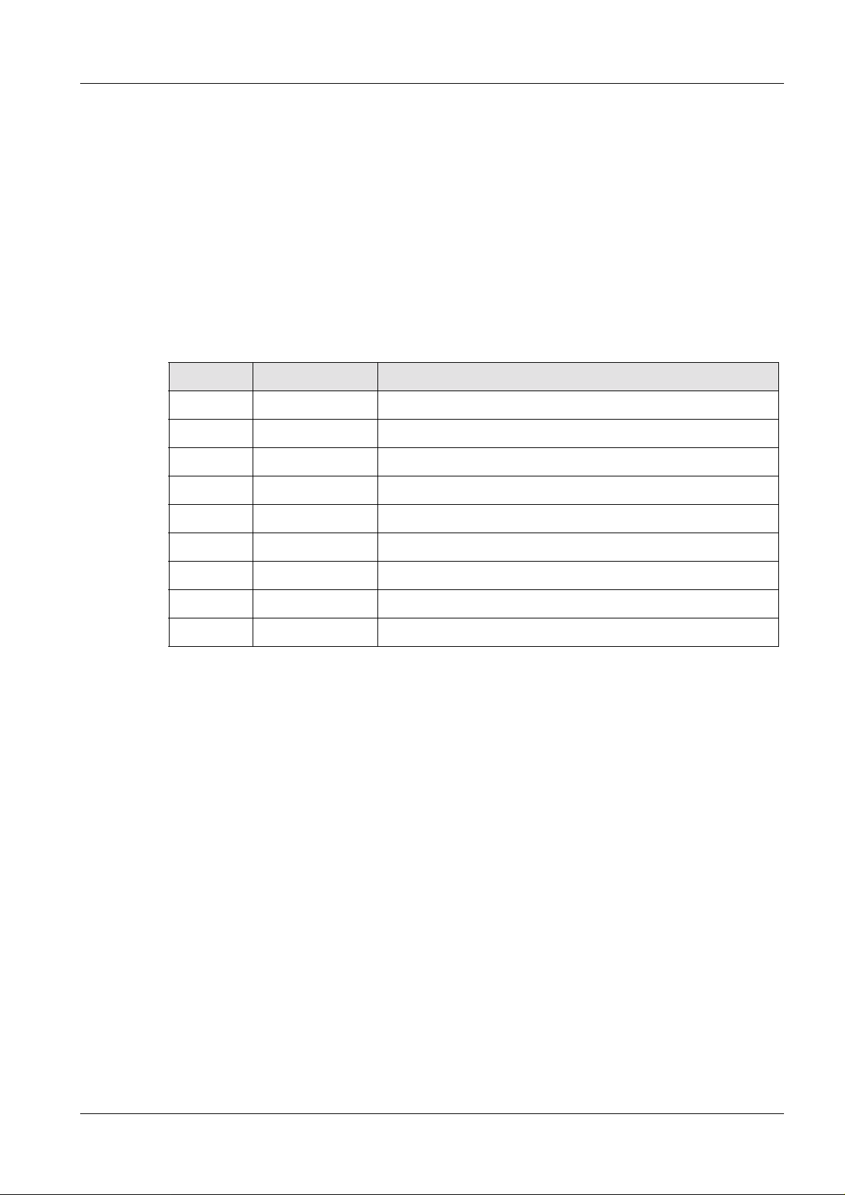
Setup 3
• Disconnect the network cables from the Fuji equipment. The original network connection
shall be restored when the AEC calibratio n has been performed.
• Connect the MAMMOMAT, Fuji FCR 5000 MA reader, Fuji CR Console and service PC
to the switch with the enclosed network cabl es (Siemens material No. 99 00 440)
according to Fig. 1. Use the same network socket s on the Fuji equipment as before.
• Connect the switch to the incoming mains.
• Connect the service PC to the MAMMOMAT according to the MAMMOMAT’s Technical
Manual.
3 - 1
MAMMOMAT 3000 Nova
Service PC Switch
Incoming mains
Fig. 1 Configuration
Image reader
Fuji CR Console
Incoming mains
Remaining wor k st eps 3
Remove and dispose of all packaging materials from the components.
Siemens-Elema AB SPB7-230.812.05 Page 1 of 2 MAMMOMAT 3000 Nova
Solna, Sweden Rev. 03 11.02 SPS-UD Installation
Page 12

3 - 2 Unpacking and setup of the AEC kit for Fuji CR
This page intentionally left blank.
MAMMOMAT 3000 Nova SPB7-230.812.05 Page 2 of 2 Siemens-Elema AB
Installation Rev. 03 11.02 SPS-UD Solna, Sweden
Page 13
Start-up of the Fuji FCR 5000MA 4
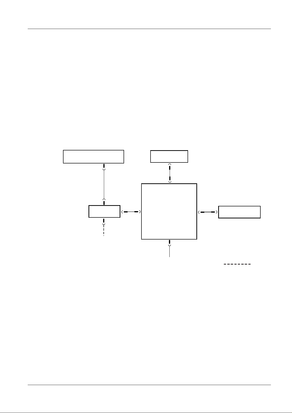
Starting up the image reader 4
1. Make sure that the power lamp on the operat ion panel lights green.
If it is not lit, the image re ader’s circuit breaker has been turned OFF. Turn the
circuit breaker back ON by turning it to the “I” side.
Power lamp
FFDM00006
4 - 1
Circuit breaker
Fig. 1 Confirming that the power lamp has lit
2. Press the system power switch ON.
FFDM00008
Fig. 2 System power switch ON
FFDM00007
Siemens-Elema AB SPB7-230.812.05 Page 1 of 2 MAMMOMAT 3000 Nova
Solna, Sweden Rev. 03 11.02 SPS-UD Installation
Page 14
4 - 2 Start-up of the Fuji FCR 5000MA
1
Erasing the IP cassette(s) 4
When conducting exposure with an IP that has been over exposed, the IP cassette must
be subjected to secondary- and primary erasure processing.
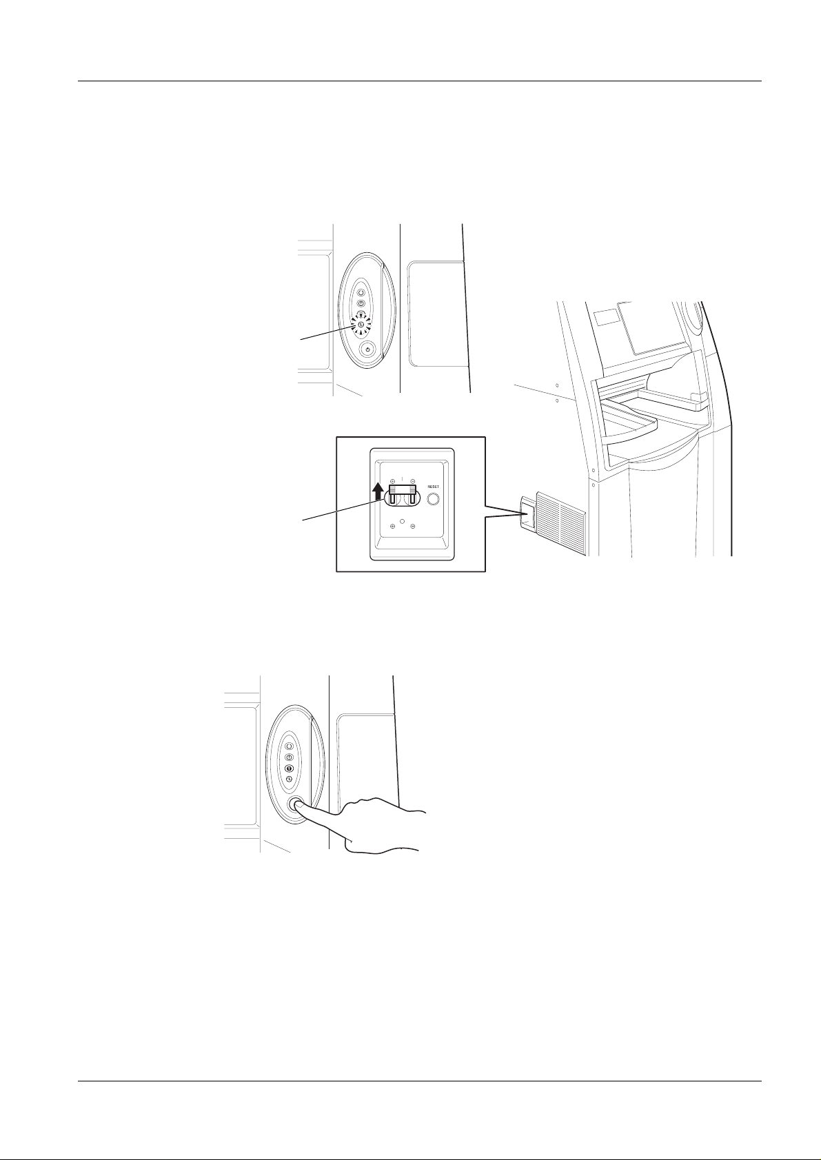
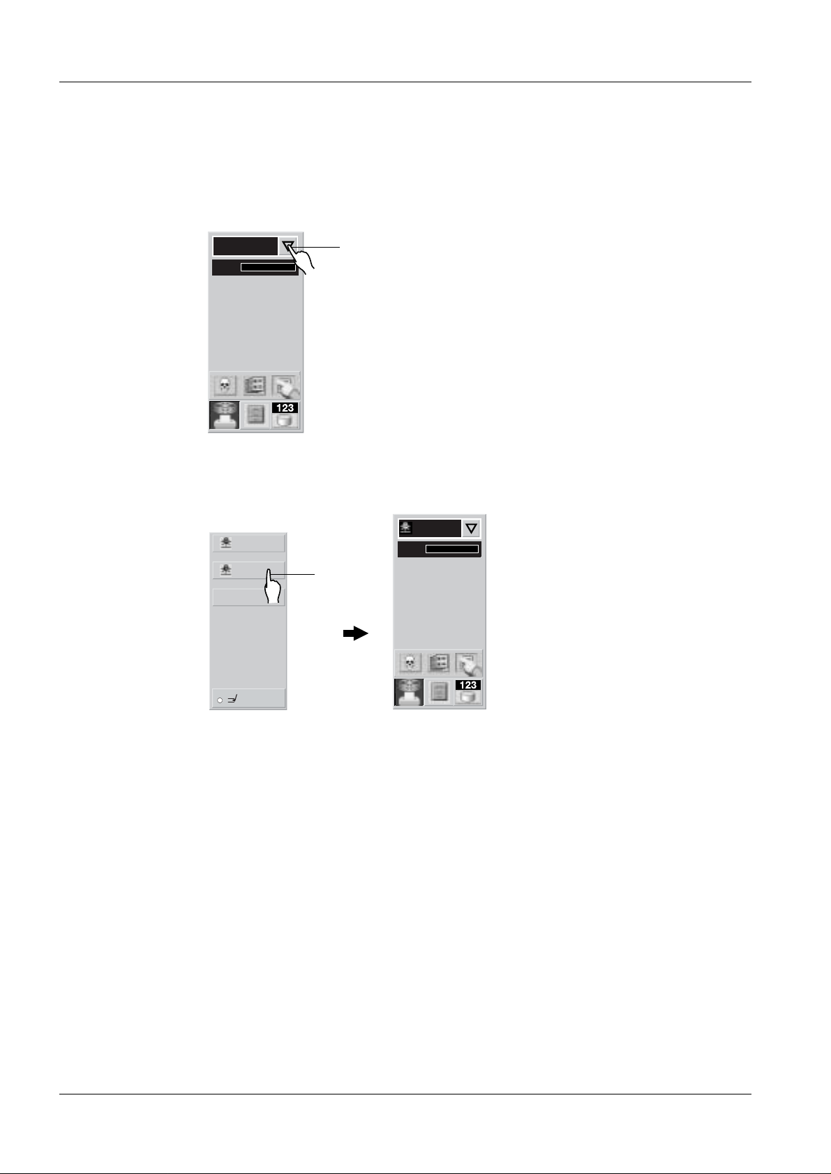
1. Touch the processing mode switchover key and the pr ocessing selection screen
will be displayed.
READING
FFDM00012
Fig. 3 Processing mode switchover key
2. Touch the secondary erasure key to select secondary erasure.
SECONDARY ERASURE
PRIMARY ERASURE
SECONDARY ERASURE
READING
URGENT
Fig. 4 Secondary erasure key
2
FFDM00013
3. Secondary erasure processing has been sele cted for the cassette to be insert ed.
Insert the appropriate ca ssette in the cassette setting uni t. The IP inside the
cassette will be subjected to secondar y erasure processing.
4. Touch the primary erasure key to selec t primary erasure.
5. Primary erasure processing has been select ed for the cassette to be inserted.
Insert the appropriate ca ssette in the cassette setting uni t. The IP inside the
cassette will be subjected to pri mary erasure processing.
MAMMOMAT 3000 Nova SPB7-230.812.05 Page 2 of 2 Siemens-Elema AB
Installation Rev. 03 11.02 SPS-UD Solna, Sweden
Page 15
Backup of Fuji CR Console 5
Make a backup of the Fuji CR Console’s original settings. The backup will be used to
restore the Fuji CR Console’s settings when the AEC calibration has been performed.
The following floppy disks are needed:
Service Utility backup floppy disks Two backup floppy disks to store Service Utility
data from before the installation, marked with “Service Utility Backup 1(2)” and “Service Utility
Backup 2(2)”.
User Utility backup floppy disks Two backup floppy disk to store User Utility from
before the installation, marked with “User Utility
Backup 1(2)” and “User Utili ty Backup 2(2) ”.
Starting the Service Ut il ity 5
The procedure for starting the Service Utility varies depending on whether the Fuji CR
Console power is ON or OFF.
When the power is OFF
Turn ON the PC power. Windows 2000 starts up. After about one minute the Fuji CR
Application starts. When the initial windo w opens , sequen tially c lic k its upper l eft and right
corners within a period of five seconds . The Service Utility starts and the IP Service Utility
window opens.
5 - 1
When the power is ON
Hold down the Shift key and choose Shut down on the menu. Keep the Shift key
pressed until the desktop screen appears. Fr om the menu, sequentially choose
Programs > Fuji Film > FCR. The Fuji CR Applic ation star ts in about one minute.
When the initial window opens, sequentially click its upper left and right corners within a
period of five seconds. The Service Utility starts and the IIP Service Utility window opens .
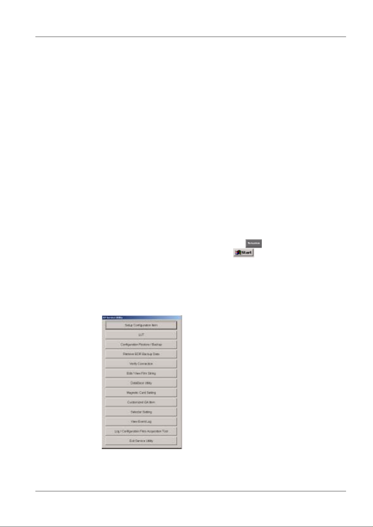
Service Utility Backup 5
1. Press the Configuration Restore / Backup button acc ording to Fig. 1.
Fig. 1 IIP Service Utility
Siemens-Elema AB SPB7-230.812.05 Page 1 of 4 MAMMOMAT 3000 Nova
Solna, Sweden Rev. 03 11.02 SPS-UD Installation
Page 16
5 - 2 Backup of Fuji CR Console
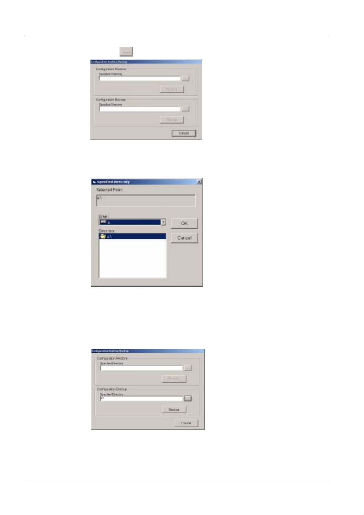
2. Press the button belonging to Configuration Bac kup according to Fig. 2.
Fig. 2 Configuration Restore / Backup
3. Insert the Service Utility Back up 1(2) floppy in drive A: Choose A: from Drive
combo box and press OK according to Fig . 3.
Fig. 3 Specified Directory
4. Press Backup button according to Fig. 4. Follow the instruct ion on the screen.
Even when the backup process ends, no message appears to indicate it. While
the process is being performed, th e mouse cursor is replaced by an hourglass
cursor. When the hourglass cursor chang es back to the mouse cursor, it means
that the process has ended.
Fig. 4 Configuration Restore / Backup
MAMMOMAT 3000 Nova SPB7-230.812.05 Page 2 of 4 Siemens-Elema AB
Installation Rev. 03 11.02 SPS-UD Solna, Sweden
Page 17
Backup of Fuji CR Console 5 - 3
5. Remove backup floppy.
6. When the process has ended, p ress Cancel button according to Fig . 4. Press Exit
Service Utility button according to Fig. 1.
7. From the menu, sequentially choose Programs > Fuji Film > FCR to start
the Fuji CR Application.
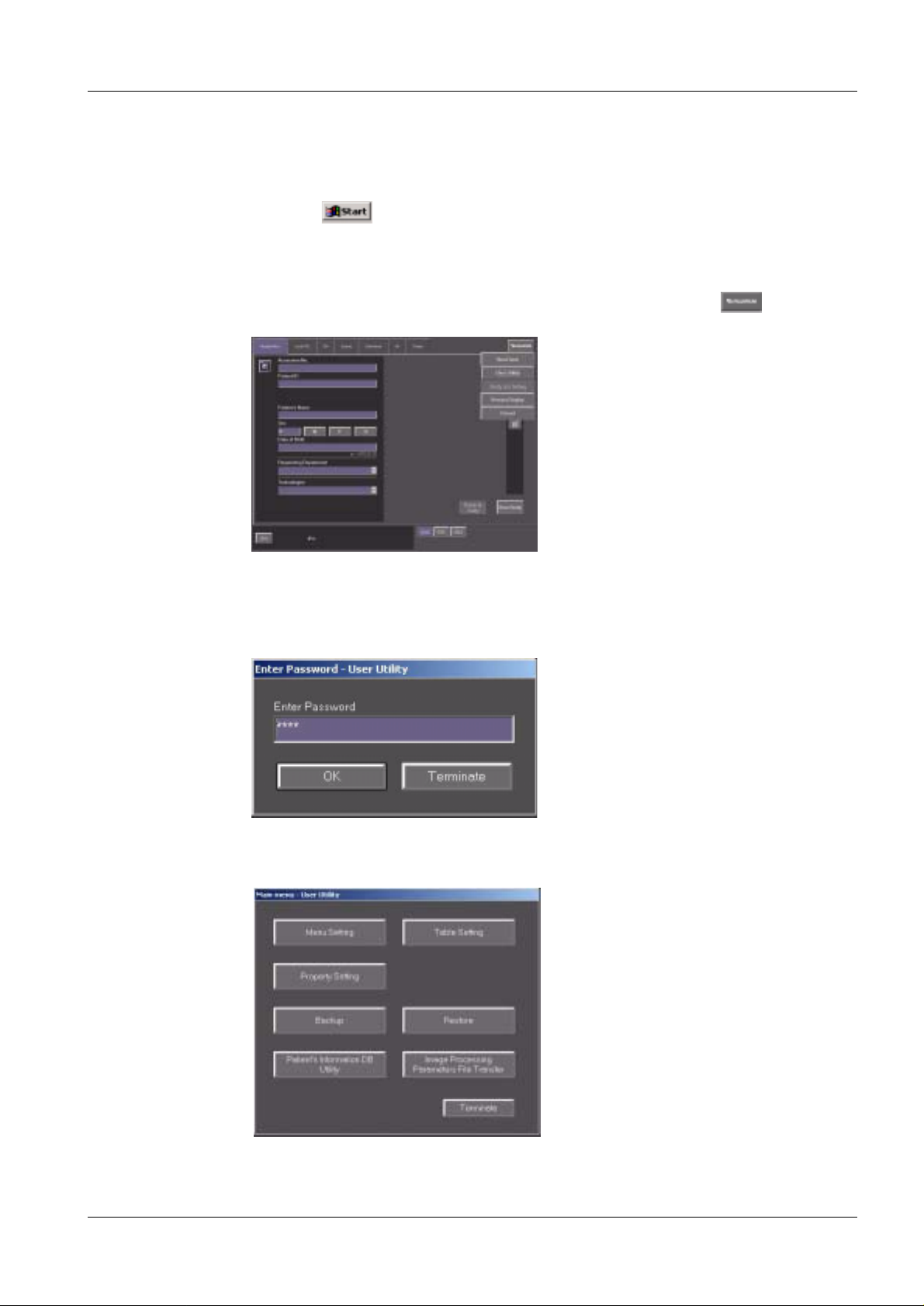
User Utility Backup 5
1. Enter the User Utility Main Menu b y choosing User Utility on the menu
according to Fig. 5.
Fig. 5 Enter User Utility
2. Press the OK button in the Enter Pass word – User Utility windo w , without
entering any pass word, according to Fig. 6.
Fig. 6 Enter Password – User Utility
3. Press Backup button according to Fig. 7.
Fig. 7 Main Menu - User Utility
Siemens-Elema AB SPB7-230.812.05 Page 3 of 4 MAMMOMAT 3000 Nova
Solna, Sweden Rev. 03 11.02 SPS-UD Installation
Page 18
5 - 4 Backup of Fuji CR Console
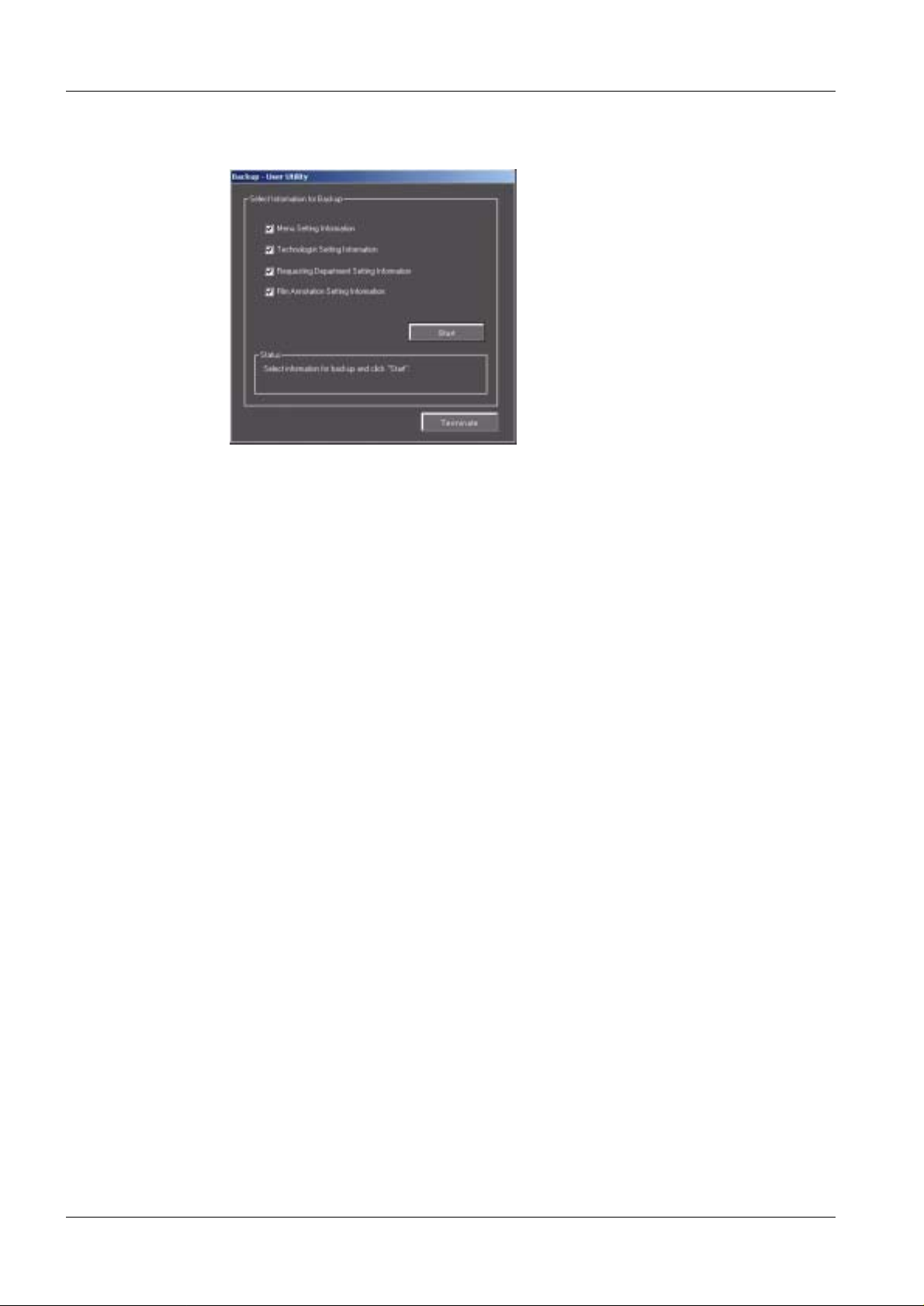
4. Insert the User Utility Back up 1(2) floppy in drive A: Mark all fo ur check boxes and
press Start button according to Fig. 8. Follow the instructi ons on the screen.
Fig. 8 Backup – User Utility
5. When the backup process is finished, pr ess the Terminate button according to
Fig. 8 and Terminate button according to Fig. 7.
MAMMOMAT 3000 Nova SPB7-230.812.05 Page 4 of 4 Siemens-Elema AB
Installation Rev. 03 11.02 SPS-UD Solna, Sweden
Page 19
Setup of service PC 6
Verify Fuji CR Console’s IP configuration 6
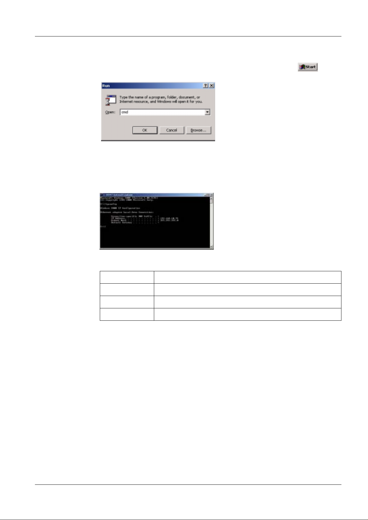
1. Verify the Fuji CR Console IP address: From t he Fuji CR Console’s menu,
choose Run…. Type cmd and press OK according to Fig. 1.
Fig. 1 Run
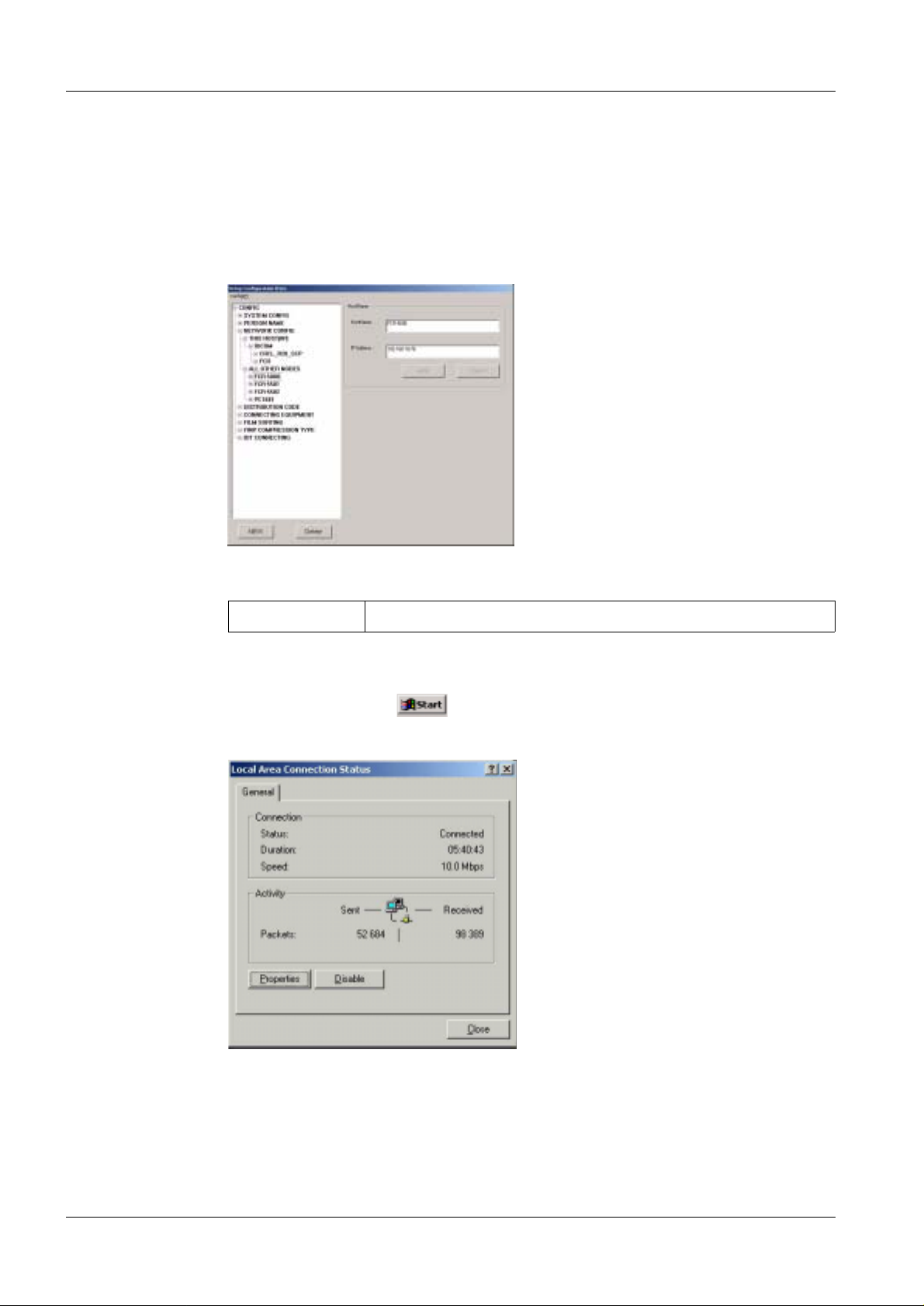
2. In the DOS prompt, type ipconfig and press Enter. The CR Console’s IP address,
subnet mask and default gateway will show accordi ng to Fig. 2 Note the
information in the table belo w.
6 - 1
Fig. 2 IP Configuration
IP address
Subnet mask
Default gateway
Hostname
3. Close Command window.
Siemens-Elema AB SPB7-230.812.05 Page 1 of 6 MAMMOMAT 3000 Nova
Solna, Sweden Rev. 03 11.02 SPS-UD Installation
Page 20
6 - 2 Setup of service PC
V erify Fuji FCR 5000MA IP configuration 6
1. Verify the Fuji FCR 5000MA IP address: Start t he Service Utility according to
"Starting the Service Utili ty" on Page 5 - 1. Press the Setup Configurati on Item
button according to Fig. 1, Page 5 - 1. Ma rk CONFIG > NETWORK CONFIG >
ALL OTHER NODES > FCR 5000 to view the Fuji reader IP address, according to
Fig. 3. Close the Service Utility by pr essing Config(F) > Close(C). Note the IP
address in the table below.
Fig. 3 Reader IP configuration
IP address
Setup of service PC IP address 6
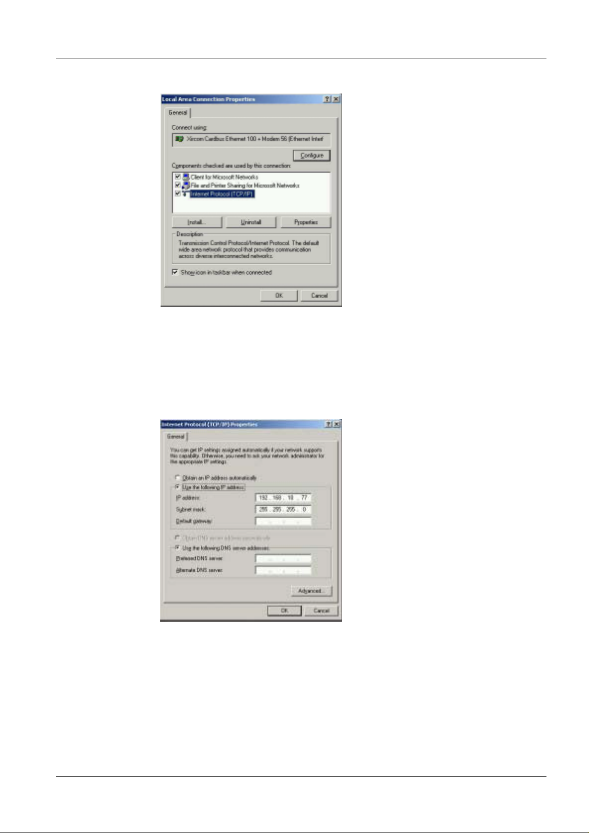
1. From the service PC’s menu, choose Settings > Control Panel >
Network and Dial-up connections > Local Area Connection. Press Properties
button according to Fig. 4.
Fig. 4 Local Area Connection Status
MAMMOMAT 3000 Nova SPB7-230.812.05 Page 2 of 6 Siemens-Elema AB
Installation Rev. 03 11.02 SPS-UD Solna, Sweden
Page 21
Setup of service PC 6 - 3
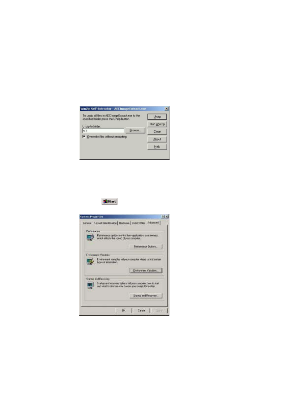
2. Mark TCP/IP and press the Properties button according to Fig. 5.
Fig. 5 Local Area Connection Properties
3. Change the service PC’s IP address in such a way t hat the three first groups are
identical to the CR Consoles (see step 2., Page 6 - 1) and the FCR 5000MA (see
step 1., Page 6 - 2), and the fourth gr oup is unique in the LAN. Change the service
PC’s Subnet Mask and Default Gateway to be ide ntical to the Fuji CR Console’s
and press OK button according to Fig. 6. Press OK but ton according to Fig. 5.
Press Close button according to Fig. 4.
Fig. 6 Internet Protocol (TCP/IP) Properties
Siemens-Elema AB SPB7-230.812.05 Page 3 of 6 MAMMOMAT 3000 Nova
Solna, Sweden Rev. 03 11.02 SPS-UD Installation
Page 22

6 - 4 Setup of service PC
Editing hosts file 6
1. The IP address of the Fuji CR Console needs to be adde d to the service PC’s
Windows file hosts. This file can be found in the direc tory
C:\WinNT\system32\drivers\etc. Open the file with e.g. Notepad and add a line
with the Fuji Consoles IP address (s ee step 2., Page 6 - 1), and a name to identify
it, according to Fig. 7. Save the fi le and exit Notepad.
Fig. 7 Edit the Windows file hosts
MAMMOMAT 3000 Nova SPB7-230.812.05 Page 4 of 6 Siemens-Elema AB
Installation Rev. 03 11.02 SPS-UD Solna, Sweden
Page 23
Setup of service PC 6 - 5
AECImageExtract installation 6
1. Start service PC.
2. Log in (make sure you have administrator ri ghts).
3. Open Windows Explorer.
4. Insert the AECImageExtract floppy i n drive A:.
5. Run the self-extracting file, AECImageExtract.exe.
6. Unzip to folder C:\, press Unzip button and press Close button according to Fig. 8.
Fig. 8 UnZip Self-Extractor
7. Remove AECImageExtract floppy.
Adding environmental variables 6
1. From the menu, choose Settings > Control Panel > System >
Advanced. Press Environmental Variables button according to Fig. 9.
Fig. 9 System Properties
Siemens-Elema AB SPB7-230.812.05 Page 5 of 6 MAMMOMAT 3000 Nova
Solna, Sweden Rev. 03 11.02 SPS-UD Installation
Page 24

6 - 6 Setup of service PC
2. Add a new User Variables for Administrator by pres sing New… button
according to Fig. 10.
Fig. 10 Environmental Variables
3. Type MERGE _INI in the Variable Name field and
C:\AECImageExtract\Merge\Mergecom.ini in the Variable Value field and
press OK button according to Fig. 11. Press OK button according to Fig. 10 and
according to Fig. 9. Restart the ser vice PC.
Fig. 11 New User Variable
Start the AECImageExtract application 6
1. Start service PC.
2. Log in (make sure you have administr ator rights).
3. Open Windows Explorer.
4. Start the AECImageExtract applicati on on the service PC by running the batch file
go.bat that can be found under the director y C:\AECImageExtract.
MAMMOMAT 3000 Nova SPB7-230.812.05 Page 6 of 6 Siemens-Elema AB
Installation Rev. 03 11.02 SPS-UD Solna, Sweden
Page 25

Setup of Fuji CR Co nsole 7
Verify the service PC’s hostname 7
1. From the service PC’s menu, choose Run…. Type cmd and press OK
button according to Fig. 1.
Fig. 1 Run cmd
2. In the DOS prompt, type “hostname” and press Enter. The service PC’ s
hostname will show according to Fig. 2. Close Command window. Note the
hostname in the table below.
7 - 1
Fig. 2 Hostname
Hostname
Siemens-Elema AB SPB7-230.812.05 Page 1 of 10 MAMMOMAT 3000 Nova
Solna, Sweden Rev. 03 11.02 SPS-UD Installation
Page 26

7 - 2 Setup of Fuji CR Console
Creating network nodes 7
1. Enter the Fuji CR Console’s IIP Servi ce Utility according to "Star ting the Service
Utility" on Page 5 - 1. Press the Setup Confi guration Item button according to
Fig. 3.
Fig. 3 Service Utility
2. Add a network node for the service PC by markin g CONFIG > NETWORK
CONFIG > ALL OTHER NODES and pressing the NEW button according to Fig.
4.
Fig. 4 Creating a new network node
MAMMOMAT 3000 Nova SPB7-230.812.05 Page 2 of 10 Siemens-Elema AB
Installation Rev. 03 11.02 SPS-UD Solna, Sweden
Page 27

Setup of Fuji CR Console 7 - 3
3. Type the service PC’s HostName (see step 2., Page 7 - 1) and IP address in
respectively field, mark DICOM check box and press OK button according to Fig.
5.
Fig. 5 Network node information
4. Type the service PC’s Application Entity Name; DICOM_HIC, which is preset by
the AECImageExtract application, type Port Number; 21760, also preset by
AECImageExtract, in respectively field, choose OD_FILE from the Attribute
combo box and press the New button according to Fig . 6.
Fig. 6 Creating Service Classes as SCP
5. Set Abstract Syntax combo box to CRImageStorage, set Role to SCP, s et
Transfer Syntax combo box to ImplicitVRLittleEndian, set Acceptable Density
to ST & HQ & SH, set Default Output Density to HQ / SH, set Image Processing
to NONE(N), clear the Multibyte check box and press the OK button according to
Fig. 7.
Fig. 7 CRImageStorage as SCP
Siemens-Elema AB SPB7-230.812.05 Page 3 of 10 MAMMOMAT 3000 Nova
Solna, Sweden Rev. 03 11.02 SPS-UD Installation
Page 28

7 - 4 Setup of Fuji CR Console
6. Press New button accordi ng to Fig. 6. Set Abstract Syntax combo box to
Verification, set Role to SCP, clear the MultiByte check box and press the OK
button according to Fig. 8. Press OK button according to Fig. 6.
Fig. 8 Verification as SCP
7. Mark the row in Network Config > This Host IIP > DICOM where the ser vice
classes has SCU roles, and press New button according to Fig. 9.
Fig. 9 Creating Service Classes as SCU
8. Set Abstract Syntax combo box to CRImageStorage, set Role to SCU, set
Transfer Syntax combo box to ImplicitVRLittleEndian, cl ear the Multibyte
check box and press the OK button according to Fig. 10.
Fig. 10 CRImageStorage as SCU
MAMMOMAT 3000 Nova SPB7-230.812.05 Page 4 of 10 Siemens-Elema AB
Installation Rev. 03 11.02 SPS-UD Solna, Sweden
Page 29

Setup of Fuji CR Console 7 - 5
9. Press the New button according to Fig. 9. Set Abstract Syntax combo box to
Verification, set Role to SCU, clear the Multibyte check box and press the OK
according to Fig. 11.
Fig. 11 Verification as SCU
10. Mark Connecting Equipment and press the New button according to Fig. 12.
Fig. 12 Connect new equipment
11. Choose, or write, OD_FILE in the Function combo box. Choose the service PC’s
AE Title in the first Equipment combo box, even th ough other equipment are
preset, and press OK button according to Fig. 13.
Fig. 13 C onnect ing service PC
12. Save Network configuration by pressing Config(F) > Save(V) in t he top left corner
according to Fig. 12. Exit the Servi ce Utility by pressing Config(F) > Close(C).
Siemens-Elema AB SPB7-230.812.05 Page 5 of 10 MAMMOMAT 3000 Nova
Solna, Sweden Rev. 03 11.02 SPS-UD Installation
Page 30

7 - 6 Setup of Fuji CR Console
V erify connection 7
1. Choose Verify Connection according to Fig. 3. Select service PC’s hostname in
the upper combo box and press Ping Network button.
2. Start AECImageExtract applicati on on service PC according to "Start the
AECImageExtract application" on Page 6 - 6.
3. Choose service PC AE Title in lower combo box and press Ver ify Connection
button. Press Close button accordi ng to Fig. 14.
Fig. 14 Verify Connection
4. Exit Service Utility by pressing Exit Serv ice Utility button according t o Fig. 3.
Create AEC Calibration exposure menu 7
1. Start the AECImageExtract applicati on on the service PC according to "Start the
AECImageExtract application" on Page 6 - 6.
2. From the menu on the Fuji CR Console, sequentially choose Programs >
Fuji Film > FCR. The Fuji CR Applicat ion starts in about one minute.
3. Choose User Utility on the menu accor ding to Fig. 15.
Fig. 15 Enter User Utility
MAMMOMAT 3000 Nova SPB7-230.812.05 Page 6 of 10 Siemens-Elema AB
Installation Rev. 03 11.02 SPS-UD Solna, Sweden
Page 31

Setup of Fuji CR Console 7 - 7
4. Press OK button in the Enter Password – User Utility window, without ent ering
any password, according to Fig. 16.
Fig. 16
5. Press Menu Setting button according to Fig. 17.
Fig. 17 User Utility Menu
6. Mark exposure menu Max 4.0 in the Exposure / Study Menu field, an d create a
new exposure menu by pressing New button according to Fig. 18.
Fig. 18 Menu Setting
Siemens-Elema AB SPB7-230.812.05 Page 7 of 10 MAMMOMAT 3000 Nova
Solna, Sweden Rev. 03 11.02 SPS-UD Installation
Page 32

7 - 8 Setup of Fuji CR Console
7. Name the new exposure menu AEC Calibration in the field ANK Exp osure Menu
Name. In Exposure Parameter 1 task card, set EDR Mode to Fix, change S
value to 121 and set Film Output Format to One Image ac cording to Fig. 19.
Fig. 19 Exposure Parameter 1
8. In Exposure Parameter 2 task card, set Film Reference Orientati on to Portrait,
Film Edge to Black and press OK button according t o Fig. 20.
Fig. 20 Exposure Parameter 2
9. Drag and drop the AEC Calibration Exposure Menu f rom the Exposure/Study
Menu field to one of the empty buttons in the TEST t ask card and press OK button
according to Fig. 21.
Fig. 21 Drag and Drop
MAMMOMAT 3000 Nova SPB7-230.812.05 Page 8 of 10 Siemens-Elema AB
Installation Rev. 03 11.02 SPS-UD Solna, Sweden
Page 33

Setup of Fuji CR Console 7 - 9
Property setting 7
1. The Property Settings has to be changed to pr event images to be sent to printers
and to other storages than the service PC.
2. Enter property setting by pressing t he Property Setting button according to Fi g.
17.
3. Set Setting of action to be taken… to Terminate Study after QA is completed.
(For Fuji CR Console software version A08: Set The method at the time pushed
“Study finish” button. (There is no unreg istration menu) to Finish exposure
& QA in the task card Study setting).
4. Set Auto-distribution Setting to Distributes automatically after QA
completion (in Fuji CR Console software vers ion A08 this is done in the task card
Distribution setting).
5. Set PRINT Attribute to (none) to prevent the AEC exposures to be printed (in Fuj i
CR Console software version A08 this is done in the task card Distribution
setting).
6. Set FILE Attribute to the service PC’s AE Title to enable automatic dist ribution of
images to the service PC (in Fuji CR Console sof tware version A08 this is done in
the task card Distribution se tting).
7. Press OK button according to Fig. 22. Exit the User Utilit y menu by pressing the
Terminate button according to Fi g. 17.
Fig. 22 Property Setting
Siemens-Elema AB SPB7-230.812.05 Page 9 of 10 MAMMOMAT 3000 Nova
Solna, Sweden Rev. 03 11.02 SPS-UD Installation
Page 34

7 - 10 Setup of Fuji CR Console
This page intentionally left blank.
MAMMOMAT 3000 Nova SPB7-230.812.05 Page 10 of 10 Siemens-Elema AB
Installation Rev. 03 11.02 SPS-UD Solna, Sweden
Page 35

Examination 8
1. Input patient informati on (either Patient ID or Patient´s Name is necessary) and
press the Exposure Menu button accor ding to Fig. 1.
Fig. 1 Patient registration
2. During the whole AEC calibration, choose t he AEC Calibration exposure menu
from the TEST task card according to Fig. 2 and press OK button.
8 - 1
Fig. 2 AEC Calibration
3. Start the study by pressing the Start St udy button according to Fig. 3.
Fig. 3 Start Study
Siemens-Elema AB SPB7-230.812.05 Page 1 of 4 MAMMOMAT 3000 Nova
Solna, Sweden Rev. 03 11.02 SPS-UD Installation
Page 36

8 - 2 Examination
4. Insert the IP cassette in the object table according to Fig. 4.
FFDM00020
Fig. 4 Insertion of IP cassette
5. Make an exposure with the MAMMOMAT. Register the cassette ei ther by the
Barcode Scanner, or by pressing the IP# but ton according to Fig. 3, and then type
the 8 digit number from the cassette according to Fig. 5 and press Enter on the
keyboard.
Fig. 5 Cassette registration
MAMMOMAT 3000 Nova SPB7-230.812.05 Page 2 of 4 Siemens-Elema AB
Installation Rev. 03 11.02 SPS-UD Solna, Sweden
Page 37

Examination 8 - 3
6. Make sure that the cassette ready lamp light s green.
Cassette ready lamp li ghts
FFDM00025
Fig. 6 Inserting the cassette
7. With the IP cassette’s barcod e window facing up and in front, insert the IP
cassette slowly straight al ong the guide on the right.
CAUTION
Be sure to insert the cassette as illustrated, straight along the
guide on the right. Cassettes that have been set upside-down, in
the wrong direction or at a slant will result in abnormalities and
may damage the equipment.
Cassette guide
FFDM00026
Fig. 7 Insert straight slowly
Siemens-Elema AB SPB7-230.812.05 Page 3 of 4 MAMMOMAT 3000 Nova
Solna, Sweden Rev. 03 11.02 SPS-UD Installation
Page 38

8 - 4 Examination
8. After approximately 60 s when the cassette removal lamp is lighting, remove the
cassette slowly and straight. (The cassette can be used directly for a new
exposure.)
FFDM00028
Fig. 8 Removing the cassette
9. When the image has been sent from the reader and app ears on the Fuji CR
Console Screen, press the button once to return to the Registrati on task
card and to send the image to the service PC acc ording to Fig. 9.
Fig. 9 Image transfer
MAMMOMAT 3000 Nova SPB7-230.812.05 Page 4 of 4 Siemens-Elema AB
Installation Rev. 03 11.02 SPS-UD Solna, Sweden
Page 39

Calibrating and adjusting the AEC 9
General 9
These instructions describe installation of AEC floppy disk with material No. 66 01 897.
This floppy di sk makes AEC tables for Fuji CR HR-BD imaging plate in IP CASS-BD M
available.
The AEC is based on correcti on tables. The tables are optimized for the IP/cassette combinations in table 1.
Table 1 Correction table identifications
Scanner IP Cassette Sensitivity Mo/Mo Mo/Rh W/Rh
9 - 1
Fuji
FCR5000MA
plus
Fuji
CR HR-BD
Fuji
IP CASS-BD M 0 1401 1402 1403
Siemens-Elema AB SPB7-230.812.05 Page 1 of 24 MAMMOMAT 3000 Nova
Solna, Sweden Rev. 03 11.02 SPS-UD Installation
Page 40

9 - 2 Calibrating and adjusting the AEC
m
A
p
Definitions 9
AD Value
D V alue
ax 1023
450
min 0
0.01 0.1 1 10
log Ex
Old backup floppy disk Backup floppy disk to store data from before the
installation. To be marked “Old backup” and with serial
No. of the MAMMOMAT system, date, and version of the
correction tables.
New backup floppy disk Backup floppy disk to store data during and after the
installation. To be marked “New backup ” and wit h serial
No. of the MAMMOMAT system, date, and version of the
correction tables.
MAMMOMAT 3000 Nova SPB7-230.812.05 Page 2 of 24 Siemens-Elema AB
Installation Rev. 03 11.02 SPS-UD Solna, Sweden
Page 41

Calibrating and adjusting the AEC 9 - 3
Protective measures 9
It is very important that any interv ention in the equipment wil l start by disconnect ing it from
the power supply with the main circuit-breaker.
WARNING
WARNING
If the system is only switched off at the control panel or with
S2/D711, line vol ta ge will still be prese nt a t the generat or l ine connection, line filter Z1, Z2, transformer T1, transformer T10 and
PC board D711 (see MAMMOMAT 3000 Nova Wiring Diagram).
Life-threatening electric shock hazard exists.
Disconnect mains cable and com ply with the information on this
page.
After shut-down of the system, there may still be 380 V DC
present on the intermediate circuit.
Life-threatening electric shock hazard exists.
The voltage level will be indicated by LED V24 on PC board D710.
The voltage will dr op to less than 30 V withi n about 3 minutes, the
LED goes out at about 30 V.
Symbols 9
Checks and adjustments that m ust be perf ormed with radi ation ON are i dentif ie d
by the radiation w a rning symbol.
Delay times between two exposures 9
Delay times listed below must be followed in order to prevent the tube from overheating.
Exposure mAs value Delay time between two exposures (seconds)
max 100 min 15
max 200 min 30
max 300 min 45
max 400 min 60
max 500 min 75
Siemens-Elema AB SPB7-230.812.05 Page 3 of 24 MAMMOMAT 3000 Nova
Solna, Sweden Rev. 03 11.02 SPS-UD Installation
Page 42

9 - 4 Calibrating and adjusting the AEC
Preparation of backup floppy 9
1. Start service PC.
2. Log in (make sure you have administr ator rights).
3. Open Windows Explorer.
4. Create a new folder under C: and name it “AEC_inst”.
5. Insert the service program floppy i n drive A:.
6. Copy the files service.exe and m300.h60 fr om A: to C:\AEC_inst.
7. Insert the floppy AEC correction tabl es in drive A:.
8. Copy all files from A: to C:\AEC_inst.
9. Mark an empty backup floppy with new backup, seri al number of the
MAMMOMAT system, version of the correction tables , and date. Insert the floppy
in drive A.
10. Copy the content of C:\AEC_inst to A:.
Use this floppy for the rest of the i nstallation.
11. Press Start and select Programs > Accessories > Command Prompt.
12. In the DOS prompt, type:
“CD \” and press Enter,
“MKDIR mammomat” and press Enter,
“CD mammomat” and press Enter,
“A:” and press Enter.
13. If AEC correction tables have been install ed on the MAMMOMAT before, make a
backup of these tables, see "Backup of ex isting system" on Page 9 - 4.
14. Start the service program by running the service.exe file from A:.
Backup of existing system 9
1. Make sure that the service fl oppy is still in drive A:.
2. Start the service program by writi ng: Service, then press Enter.
3. - In the log in-menu, enter your name and pr ess Enter.
- Type the password for the service progra m and press Enter.
- In Program-mode set: normal.
4. Check that service program version 4. 3 or higher is used. The version is shown in
the top left corner of th e display.
5. In Mainmenu select Configuration > Power. Note the displayed power values in
the test protocol on Page 12 - 1.
6. Take the backup to hard disk: Backup > Copy insta llation area to disk > All.
7. Take out the floppy with the service pro gram and insert an empty floppy disk and
mark it with old backup, serial number of system, version of the cor rection tables,
and date. This floppy is defined as old backu p floppy.
8. In Mainmenu select Configuration > Save config file. Press F2 t o save.
9. In Mainmenu select Service > Copy error buffer to file.
MAMMOMAT 3000 Nova SPB7-230.812.05 Page 4 of 24 Siemens-Elema AB
Installation Rev. 03 11.02 SPS-UD Solna, Sweden
Page 43

Calibrating and adjusting the AEC 9 - 5
10. If the MAMMOMAT is equipped with OPDOSE, press the left progr am button on
the panel. Note the displayed exposu re settings in the test protocol on Page 12 - 1.
Repeat for all four programs. Ente r menu Configuration > Miscellaneous >
Auto limits. Note the three values in test protocol on Page 12 - 1, in colu mn
“Breast thickness”.
11. Quit the service program by pres sing F10.
12. Type “C:” and press Enter.
13. Type “COPY *.TXT A:” and press Enter.
14. Check that the following backu p files are stored on the floppy disk ( by typing
“dir a:”, then pressing Enter):
- a_backup.txt for AEC parameters
- s_backup.txt for stand parameter s
- p_backup.txt for panel parameter s
- momo_h.txt for AEC correction tables
- morh_h.txt for AEC correction tabl es
- wrh_h.txt for AEC correction tabl es
- momo_d.txt for AEC correction tables
- morh_d.txt for AEC correction tabl es
- wrh_d.txt for AEC correction tabl es
- mammo.cfg for configuration parameters
- errorbuf.txt for err or log
15. Type “DEL *.TXT” and press Enter.
16. Remove the floppy disk and make it write pr otected.
17. Insert the new backup floppy in drive A:.
18. Start the service program by r unning the service.exe file from A:.
Siemens-Elema AB SPB7-230.812.05 Page 5 of 24 MAMMOMAT 3000 Nova
Solna, Sweden Rev. 03 11.02 SPS-UD Installation
Page 44

9 - 6 Calibrating and adjusting the AEC
Definitions 9
Object table group 9
An object table group contai ns all object tab les of the same type. There are four groups of
object tables - Grid, No grid, Magni fication and Stereo. For ex ample the obj ect tab le group
Grid, consists of Grid 18x24 and Grid 24x30.
NOTE
Stereo shall not be used together with Fuji CR.
General conditions 9
When performing the settings in this chapter, there are some general conditions valid for
all settings:
• The detector is to be in chest wall position.
MAM00616
• The AEC calibration plexi (material No. 65 61 224 and 65 61 232) must extend at least 10
mm beyond the chest wall edge of the table and be centere d. Place the AEC calibration
plexi in the same position for all exposures.
Calibration conditions 9
Compression plate must not be used during the calibration of corre ction tables. From the
point sensitivity correction (fine setting) a compression plate may be used.
Reference IP cassette 9
Every DIGISCAN M system should have a reference IP cassette. Use this reference IP
cassette where required and for the settings in this chapter. If there is no dedicated reference IP cassette, pick one IP cassette, mark it and use it for the settings in this chapter.
Mains voltage 9
Unless otherwise stated, the mains voltage and system must be ON and the service program running, before performing any setting in this chapter.
Sensitivity conditions 9
• One step (1/8 E.P.) corresponds to approximately 4 AD Values.
MAMMOMAT 3000 Nova SPB7-230.812.05 Page 6 of 24 Siemens-Elema AB
Installation Rev. 03 11.02 SPS-UD Solna, Sweden
Page 45

Calibrating and adjusting the AEC 9 - 7
Overview of work routine 9
Main menu
Configuration
Service
Normal mode
Test DUEP Communic.
Backup
Quit
Configuration
System type
Anode
Show configuration file
Save configuration file
AEC
Miscellaneous
Filament
AEC
Reset installation parameters
Detector normalization
AEC Correction tables
Sensitivity correction
Copy H to D
Copy D to H
Sensitivity
MAM00611
1. "AEC Correction tables" on Page 9 - 9.
2. "Sensitivity correcti on (fine setting)" on Page 9 - 17.
3. "Sensitivity" on Page 9 - 19.
Siemens-Elema AB SPB7-230.812.05 Page 7 of 24 MAMMOMAT 3000 Nova
Solna, Sweden Rev. 03 11.02 SPS-UD Installation
Page 46

9 - 8 Calibrating and adjusting the AEC
DLF switch off 9
Deactivate the DLF switch. In Main menu select Configuration > Miscellaneous > DLF
switch. Press spa c e to se t switc h to O F F. Pre ss F2 to save.
Cassette loaded 9
In Mainmenu select Configuration > Miscellaneous > Cassette loaded check. Press
space to set switch to OFF. Press F2 to save.
Increase grid speed 9
Increase the grid speed. In Main menu select Configuration > Grid speed. Set the fo l-
lowing values. Press F2 to save.
Grid
Grid fast speed time 1500
Grid fast speed 90
Grid slow speed 30
<ESC> to exit, <TAB> move to next entry field
1 Help 2 Save 3 45678910Quit
ms (2.5 s max)
% of max
% of max
MAM00761
MAMMOMAT 3000 Nova SPB7-230.812.05 Page 8 of 24 Siemens-Elema AB
Installation Rev. 03 11.02 SPS-UD Solna, Sweden
Page 47

Calibrating and adjusting the AEC 9 - 9
AEC correction tab
AEC Correction tables 9
This section will guide you through the following steps:
• Installation of correction tables (F2).
• Calibration of correction tables (F3), inclu ding rough setting of sensitiv ity correction.
The AEC uses one correction table for each Anode/Filter/Speed combination. Each correction table has separ ate corrections for eac h object tabl e group (Magnifi cation, Grid and
No grid).
Installation of AEC correction tables 9
1. Start the AECImageExtract applicat ion on the service PC by running the batch fi le
go.bat that can be found under the direc tory C:\AECImageExtract.
2. In Mainmenu select Configuration > AEC > AEC correction tables.
Fig. 1
The dashes in the ID column show that no correct ion table is installed (
).
AEC correction tab
Existing tables in the AEC:
Anode/Filter Speed ID Calibrated
Mo/Mo H ---- --- --- --- --Mo/Mo D ---- --- --- --- --Mo/Rh H ---- --- --- --- --Mo/Rh D ---- --- --- --- --W/Rh H ---- --- --- --- --W/Rh D ---- --- --- --- ---
<ESC> to exit, <F2> to install new table, <F3> to calibrate existing
1 Help 2 Inst Cal3 45678910Quit
Fig. 1 AEC correction tables
NOTE
Install the correction tables on D only!
les
Mag Grid No grid Stereo
MAM00599
Siemens-Elema AB SPB7-230.812.05 Page 9 of 24 MAMMOMAT 3000 Nova
Solna, Sweden Rev. 03 11.02 SPS-UD Installation
3. Make sure that the new backup floppy is in serted.
4. Decide for which combination you need to in stall correction table. (F or av ailable
identifications for correc tion tables see Tabl e 1, Page 9 - 1 or the new back up
floppy.)
Page 48

9 - 10 Calibrating and adjusting the AEC
5. Place the cursor by one of the desired Anod e/Filter/Speed combinations. Press
F2.
Install new table
New ID: 0000
<F2> to continue, <ESC> to exit
MAM00600
6. Type the ID number of the new correction table ( see Table 1, Page 9 - 1) in the
dialog which appears. Press F2 to ins tall the table. A message box will appear
before the correction file has been f ound.
Searching for correction file...
MAM00736
Installing correction table
ID: 1401 for Mo/Mo D
29% done
MAM00880
7. When the transaction of tables is finished, a dialog like Fig. 2, Pag e 9 - 12 will
appear. To complete the calibr ation, proceed from step 5 of that se ction.
NOTICE
In order to resume calibrati ng aft e r having quit the program:
Follow the instructions from step 1 under "Calibrate correction
tables" on Page 9 - 11.
MAMMOMAT 3000 Nova SPB7-230.812.05 Page 10 of 24 Siemens-Elema AB
Installation Rev. 03 11.02 SPS-UD Solna, Sweden
Page 49

Calibrating and adjusting the AEC 9 - 11
AEC correction tab
Calibrate correction tables 9
NOTE
The new backup floppy must be inserted.
The Anode/Filter/Speed combinations should be cali brated one at a time.
1. In Mainmenu select Configuration > AEC > AEC correction tables.
AEC correction tab
Existing tables in the AEC:
Anode/Filter Speed ID Calibrated
Mo/Mo H ---- --- --- --- --Mo/Mo D 1401 No No No No
Mo/Rh H ---- --- --- --- --Mo/Rh D 1402 No No No No
W/Rh H ---- --- --- --- --W/Rh D 1403 No No No No
<ESC> to exit, <F2> to install new table, <F3> to calibrate existing
1 Help 2 Inst Cal3 45678910Quit
les
Mag Grid No grid Stereo
MAM00881
NOTICE
All object table groups and Anode / Filter combinations available
at the site must be calibrated prior to release for clinical use.
2. Place the marker by one of the desired Anode/Fil ter/Speed combinations. Press
F3 to transfer the table.
3. This message box is displayed while the serv ice program receives the correction
table.
Receiving correction table
for Mo/Mo D
63% done
MAM00882
Siemens-Elema AB SPB7-230.812.05 Page 11 of 24 MAMMOMAT 3000 Nova
Solna, Sweden Rev. 03 11.02 SPS-UD Installation
Page 50

9 - 12 Calibrating and adjusting the AEC
4. When the transfer is done, the dialog Calibr ation AEC correction table appears.
Calibration AEC correction table
Mo/Mo D, Table ID: 1401
Object table group
Magnification Not calibrated
Grid Not calibrated
No grid Not calibrated
Stereo Not calibrated
<ESC> to exit, <F2> to save, <F3> to calibrate, <F4> to clear calibration
1 Help 2 Save Cal3 45678910Quit
Fig. 2 Dialog Calibration AEC correction table shows which object tables, in the current Anode/Filter/Speed
combination, have been calibrated.
Clear
5. To calibrate the correction table for an object table group, place the cur sor in front
of the group. Press F3.
Please mount a
grid table
and press <ENTER> to continue
or <ESC> to cancel.
<ENTER> - ok / <ESC> - cancel
6. Follow the instructions in the message box above and press Enter.
Sensitivity correction
MAM00608
MAM00883
Used: 0
New: 0
<F2> save, <F3> exp support, <F4> continue, <ESC> exit
Fig. 3 Dialog Sensitivity correction
MAM00764
7. Before calibrating the in stalled correction tab les, it is necessary to make a rough
setting of the sensitivity c orrection for the chosen object tab le group .
8. Insert the referenc e IP cassette in the object table.
NOTE
MAMMOMAT 3000 Nova SPB7-230.812.05 Page 12 of 24 Siemens-Elema AB
Installation Rev. 03 11.02 SPS-UD Solna, Sweden
Make sure the new backup floppy is inserted.
Page 51

Calibrating and adjusting the AEC 9 - 13
NOTE
9. Press F3.
10. Follow the instruction s in the message box in the service program, press Enter
and perform an examination according to "Examination" on Page 8 - 1.
11. Register the AD Value (Average p ixel value for the area of interest ) that is
displayed in the AECImageExtract window at the service PC.
12. If the value differs f rom 450, switch to the service program, adj ust the values in
dialog AEC - Sensitivity correction (Fig. 3) according to the Rough ref erence value
displayed in the AECImageExtract window.
13. Save the new Sensitivity correct ion value with F2. Repeat the procedures
described from step 8 to step 13 until th e value is within 450+2.
If the value is satisfacto ry, proceed by pressing F4.
Do not use a compression plate.
Please put x cm of Plexi
on the object table.
Perform an exposure and
press <ENTER> when ready
or <ESC> to cancel.
<ENTER> - ok / <ESC> - cancel
MAM00728
NOTE
NOTE
One adjustment step of sensitivity correction (1/8 E.P .)
corresponds to approximately 4 AD Values, i.e.
450 x–
----------------- -y=
4
x = obtained AD Value
y = suggested adjustment for sensitivity correction
It is important to use 450 and the specified AEC calibration plexi
(material No. 65 61 224 and 65 61 232) during the procedures
under “Calibrate correction tables”, since measurements are
relative to factory results at 450.
The AD Value preferred by the customer can be adjusted later
either in Sensitivity correction or Sensitivity.
Siemens-Elema AB SPB7-230.812.05 Page 13 of 24 MAMMOMAT 3000 Nova
Solna, Sweden Rev. 03 11.02 SPS-UD Installation
Page 52

9 - 14 Calibrating and adjusting the AEC
14. Take another IP cassette than the ref erence IP cassette. Since it will not be
developed, the IP cassette can be used for all exposures during the followin g
calibration.
NOTE
Using secondary erasure, erase the used IP cassette after the
fourth exposure, otherwise the IP cassette cannot be utilized for
one day.
Calibration object table group
Mo/Mo D, Table ID: 1401, Object table group Grid
Exp. Plexi kV Dose rate Diff. from nominal
1 3 25 --------- ------2 3 28 --------- ------3 4 25 --------- ------4 4 32 --------- ------5 4 35 --------- ------6 6 25 --------- ------7 7 28 --------- ------8 7 32 --------- ------9 7 35 --------- -------
<ESC> to exit, <F2> to calibrate & save, <F3> to measure dose rate
1 Help 2 Save Exp support3 4 5 6 7 8 9 10 Quit
MAM00885
Fig. 4 Dialog Calibration object table group shows the dose rates for a number of exposures. The dashed
lines below Dose rate indicate that no exposures have been performed yet.
15. To proceed with the calibration, pl ace the cursor by one of the alternativ es. Press
F3.
Please put x cm of Plexi
on the object table.
Perform an exposure and
press <ENTER> when ready
or <ESC> to cancel.
<ENTER> - ok / <ESC> - cancel
16. Follow the instructions in the message box shown.
NOTE
Do not use 2 8 1 cm plexi plates instead of a 2 cm plate.
MAM00728
MAMMOMAT 3000 Nova SPB7-230.812.05 Page 14 of 24 Siemens-Elema AB
Installation Rev. 03 11.02 SPS-UD Solna, Sweden
Page 53

Calibrating and adjusting the AEC 9 - 15
17. When the exposure is done, the di alog Calibration exposure appea rs with values
for Dose rate and Diff. from nominal.
Calibration exposure
Mo/Mo D, Table ID: 1401, Object table group Grid
Exp. 5
Tension 25 kV
PMMA 4 cm
Dose rate 267.23
Diff. from nominal -21.47%
<ESC> to exit, <F2> to save, <F3> to perform exposure
1 Help 2 Save Exp support3
5678910
4
Quit
MAM00884
NOTE
If the Diff. from nominal exceeds &50% ensure that the exposure
really has taken place, the thickness of AEC calibration plexi
(material No. 65 61 224 and 65 61 232) is correct and properly
positioned and that the cassette (loaded with IP) is in serted and
repeat the last exposure. If the difference still exceeds +50%
accept the value and proce ed.
18. Save the values with F2.
19. Repeat steps 15 to 18 until all exposur es are done.
20. Perform a secondary- and a primary erasur e of the IP cassette according to
"Erasing the IP cassette(s)" on Page 4 - 2.
21. When all exposures for one object t able group are done, save the values with F2
in the dialog Calibr ation object table group.
22. The dialog Calibration AEC correct ion table appears. Select the next obje ct table
group and repeat steps 5 to 22.
23. When all desired object t able groups are calibrated, pre ss F2 to install the
calibrated correction table in the AEC.
Installing correction table
ID: 1401 for Mo/Mo D
29% done
MAM00880
24. The dialog AEC correction tabl es appears. Repeat from step 2 until all avail able
Anode/ Filter combinations are cali brated.
Siemens-Elema AB SPB7-230.812.05 Page 15 of 24 MAMMOMAT 3000 Nova
Solna, Sweden Rev. 03 11.02 SPS-UD Installation
Page 54

9 - 16 Calibrating and adjusting the AEC
Recalibration of an object table 9
An already calibrated object table group can be recalibrated.
NOTE
1. Repeat the procedure described in steps 1 to 4, Page 9 - 11.
2. To recalibrate a correction table for an object table group, place the cur sor in front
of the group. Press F4. This will res et the existing calibration of the chosen object
table group and replace it with the origi nal correction table stored on the fl oppy.
3. Press F2 to save.
4. Recalibrate the desired object tabl e group according to the normal procedure,
from step 2, Page 9 - 11.
Make sure the new backup floppy is inserted.
MAMMOMAT 3000 Nova SPB7-230.812.05 Page 16 of 24 Siemens-Elema AB
Installation Rev. 03 11.02 SPS-UD Solna, Sweden
Page 55

Calibrating and adjusting the AEC 9 - 17
MAM00532
Sensitivity correction (fine setting) 9
NOTE
New backup floppy must be inserted. The specified AEC
calibration plexi (material No. 65 61 224 and 65 61 232) must be
used.
When all desired object table groups are calibrated, a fine setting of the sensitivity correction should be performed for all av ailable object tables.
AEC - Sensitivity correction
HD
Mo/Mo Mo/Rh W/Rh Mo/Mo Mo/Rh W/Rh
Grid 18x24 0 00 000
Grid 24x30 0 0 0 0 0 0
No grid 18x24 0 0 0 0 0 0
No grid 24x30 0 0 0 0 0 0
Magnification 1.5 0 0 0 0 0 0
Magnification 1.8 0 0 0 0 0 0
Stereo 0 0 0 0 0 0
valid entries from -120 to 120 in 1/8 E.P. (+/-15 E.P.)
<ESC> to exit, <TAB> move to next entry field, <F2> to save, <F3> exp support
1 Help 2 Save 3 45678910Quit
Fig. 5 Set the sensitivity correction for all desired object tables.
Exp support
1. In Mainmenu select Configuration > AEC > Sensit ivity correction.
2. Install an object table.
3. Insert the reference IP cass ette in the object table.
4. Perform an examination according to " Examination" on Page 8 - 1.
NOTE
From this point forward a compression plate may be used.
5. Register the AD Value (Average pixel val ue for the area of interest) t hat is
displayed in the AECImageExtract window at the service PC.
6. If the value differs from 400 (fact ory recommended value) or the customer
preferred value, switch to t he service program, adjust the valu es in dialog AEC -
Sensitivity correction (Fig. 3) according to the Fine reference value displayed in
the AECImageExtract window.
7. The AD value should be as close to 400 (or by customer pre ferred) as possible.
One adjustment step of sensiti vity correction (1/8 E.P.) corresponds to
approximately 4 AD Values. If the value i s more than 4 AD Values from the
preferred value, switch t o the service program and adjust the va lues in dialog AEC
Siemens-Elema AB SPB7-230.812.05 Page 17 of 24 MAMMOMAT 3000 Nova
Solna, Sweden Rev. 03 11.02 SPS-UD Installation
Page 56

9 - 18 Calibrating and adjusting the AEC
- Sensitivity correc tion (Fig. 5). Save with F2. Repeat the pr ocedure described in
steps 3 to 5.
NOTE
One adjustment step of sensiti vity correction (1/8 E.P.)
corresponds to approximately 4 AD Values, i.e.
400(or customer preferred) x–
--------------------------------------------------------------------------y=
4
x = obtained AD Value
y = suggested adjustment for sensitivity correction
8. Repeat this procedure for the other obj ect tables if applicable.
MAMMOMAT 3000 Nova SPB7-230.812.05 Page 18 of 24 Siemens-Elema AB
Installation Rev. 03 11.02 SPS-UD Solna, Sweden
Page 57

Calibrating and adjusting the AEC 9 - 19
M
Sensitivity 9
Adjustment of AD Value for the whole AEC is performed under Mainmenu > Configuration > AEC > Sensitivity.
AEC - Sensitivity
HD
Sensitivity 0 0
valid entries from -64 to 64 in 1/8 E.P. (+/-8 E.P.)
<ESC> to exit, <TAB> move to next entry field
NOTE
Save
The AD Value preferred by the customer can be set with this
1 Help 2 3 5 678910Quit
function. The customer’s own phantom(s) can also be used.
AM00654
Siemens-Elema AB SPB7-230.812.05 Page 19 of 24 MAMMOMAT 3000 Nova
Solna, Sweden Rev. 03 11.02 SPS-UD Installation
Page 58

9 - 20 Calibrating and adjusting the AEC
Testing the AEC-function 9
AEC performance test 9
Testing of the AEC-function is to be performed according to the test protocol on
Page 12 - 2, and for the object tables in question. (Should error codes Er013 or Er450
appear; change to AEC
calibration plexi (material No. 65 61 224 and 65 61 232) which is 1 cm thinner.)
NOTE
Tolerance only valid for IP/cassette combinations list ed in
Table 1 under "General" on Page 9 - 1.
Image detector dose 9
1. Position 3-5 cm plexi on the grid object table. Be careful to position th e plexi so
that it is overlapping the chest wall edge with approximately 1 cm, in order for the
AEC to operate in a correct way.
2. Insert the reference IP cas ette in the grid object table.
3. Make an AEC exposure with 28 kV and Mo/Mo. Select the AEC D button to use
the AEC mode.
4. Record the indicated mAs value in the test pr otocol.
5. Remove the reference IP cassette.
6. Position the ionization chamber ins ide the cassette compartment above the AEC
detector.
7. Manually select (on the control panel of MAMMOMAT 3000 Nova) the mAs value
that is closest to the measured AEC mAs value and use i t during the following
measurements (with AEC mode disabled).
8. Make an exposure with 28 kV and Mo/Mo.
9. Read the dose from the ionization chamber and reco rd the value in the test
protocol. The image detector dose shall not exceed 100 mGy (10mr ad), the
recommended dose is 70 mGy.
MAMMOMAT 3000 Nova SPB7-230.812.05 Page 20 of 24 Siemens-Elema AB
Installation Rev. 03 11.02 SPS-UD Solna, Sweden
Page 59

Calibrating and adjusting the AEC 9 - 21
Reinstall/Inst a ll program para meters for OPDOSE 9
NOTE
If OPDOSE shall be used for the IP cassettes, the following steps
must be done.
1. If the system is ON and the service progr am is running, go to step 4, else go to
step 2.
2. System ON.
3. Start up the service program.
4. In Mainmenu select Configuration > Miscellaneous > Panel progra mming.
The panel program switch must be ON. Save with F2.
5. In Mainmenu select Configuration > Miscellaneous > Auto limits. Make sure
the values are Program 1 30 mm, Program 2 45 mm and Program 3 60 mm or
the values desired by the customer. Chang e if needed and then save with F2.
6. Set kV (1/Fig. 6), density (2/ Fig. 6), H/D (3/Fig. 6) and anode/fi lter combination
(4/Fig. 6), for one of the progr ams according to the test valu es previously noted in
the protocol, except density co rrection which should be set to 0.
7. Save the program parameters if needed by press ing the store button (6/Fig. 6)
and then the program button (5/Fig. 6) . Keep both buttons pressed until t he
program button stops flashing (ap proximately 5 s). Repeat the procedure in st ep 5
to 6 for the remaining programs.
Fig. 6
WARNING
W
Mo
kV
1
2
AECmAs
3
Mo
Rh Rh
Mo
Program
4
5
Auto
Lim.
MAM00018
6
Siemens-Elema AB SPB7-230.812.05 Page 21 of 24 MAMMOMAT 3000 Nova
Solna, Sweden Rev. 03 11.02 SPS-UD Installation
Page 60

9 - 22 Calibrating and adjusting the AEC
Factory settings 9
Changes can be made with the service program (Configuration, Miscellaneous, Auto limits).
Thickness
≥ 61 mm 26 W / Rh
46 - 60 mm 27 Mo / Rh
31 - 45 mm 27 Mo / Mo
0 - 30 mm 26 Mo / Mo
Fig. 7 Installations with filter disc Mo 0.030 / Rh 0.025 / Rh 0.050
Thickness
≥ 61 mm 28 Mo / Rh
46 - 60 mm 27 Mo / Rh
31 - 45 mm 27 Mo / Mo
0 - 30 mm 26 Mo / Mo
Fig. 8 Installations with filter disc Mo 0.030 / Rh 0.025
kV Anode/filter
kV Anode/filter
combination
combination
MAMMOMAT 3000 Nova SPB7-230.812.05 Page 22 of 24 Siemens-Elema AB
Installation Rev. 03 11.02 SPS-UD Solna, Sweden
Page 61

Calibrating and adjusting the AEC 9 - 23
Testing OPDOSE
1. Mount an 18x24 cm compression plate to the MAMMOMAT 3000.
2. Select a thickness of AEC calibration plexi (material No. 65 61 224 and 65 61
232), that is within the thicknes s interval of the program to be test ed. The
thickness intervals can be found in Mai nmenu > Configuration > Misce llaneous
> Auto limits. For more information about Auto limits, s ee Chapter
“Miscellaneous -> Auto limits” in t he service manual “Service Program” for
MAMMOMAT 3000.
3. Select AUTO on control panel.
4. Place the AEC calibration plexi on the object table in question and compress to 6
kg or more.
5. Check that the correct program is bl inking on the control panel. Sel ect the
program by pressing the corresponding pr ogram button on the control panel.
6. Perform an examination according to " Examination" on Page 8 - 1, use the
BREAST, L (DSR) exposure menu from the BREAST task card.
7. Register the AD Value (Average pixel val ue for the area of interest) t hat is
displayed in the AECImageExtract window at the service PC.
8. The AD Value shall be as close to 400 as possible (or the density preferred by
customer). If necessary adjust density correction on control panel. Save by
pressing the store button and then the program button. Keep both butt ons pressed
until the program button stops flash ing.
9. Repeat the procedure described in steps 2 to 8 f or the other used programs.
10. Note the OPDOSE settings in the attached test protocol.
Final procedures 9
1. If the service program is running, go to step 7., else go to step 2..
2. Start service PC.
3. Log in (make sure you have administrator ri ghts).
4. Press Start and select Programs > Accessories > Command Prompt.
5. Type “CD mammomat” and press Enter. Make sure that the new bac kup floppy is
inserted. Type “A:” and press Enter .
6. Start the service program by writ ing: Service, then press Enter.
7. Activate the DLF switch. In Main menu select Configuration > Miscellaneous >
DLF switch, press space to set switch to ON. Press F2 to save.
8. In Mainmenu select Configuration > Miscellaneous > Cassette loaded check .
Set to ON.
Siemens-Elema AB SPB7-230.812.05 Page 23 of 24 MAMMOMAT 3000 Nova
Solna, Sweden Rev. 03 11.02 SPS-UD Installation
Page 62

9 - 24 Calibrating and adjusting the AEC
9. Reduce the grid speed. In Main menu select Configurat ion > Grid speed. Set
the following values. Press F2 t o save.
Grid
Grid fast speed time 500
Grid fast speed 80
Grid slow speed 20
<ESC> to exit, <TAB> move to next entry field
1 Help 2 Save 3 4 5 6 7 8 9 10 Quit
ms (2.5 s max)
% of max
% of max
10. In Main menu select Service > Copy error buffer to file.
11. Take the backup to hard disk: Backup > Copy insta llation area to disk > All.
12. Make sure the new backup floppy is insert ed, marked with serial number of
system and version of the correction t ables (can be found on the AEC floppy disk
with material No. 66 01 897).
13. In Mainmenu select Configuration > Save config file. Press F2 to save.
14. In Mainmenu select Service > Dele te error buffer. Press y to delete.
15. Quit the service program by pres sing F10.
16. Type “C:” and press Enter.
17. Type “COPY *.TXT A:” and press Enter.
18. Check that the following backup fil es are stored on the floppy disk (by typi ng
“dir a:”, then pressing Enter):
MAM00762
- a_backup.txt for AEC parameter s
- s_backup.txt for stand parameter s
- p_backup.txt for panel par ameters
- momo_h.txt for AEC correction tables
- morh_h.txt for AEC correction tabl es
- wrh_h.txt for AEC correction tabl es
- momo_d.txt for AEC correction tables
- morh_d.txt for AEC correction tabl es
- wrh_d.txt for AEC correction tabl es
- mammo.cfg for configuration parameter s
- errorbuf.txt for err or log
19. Type “DEL *.TXT”.
20. Type “CD..”.
21. Type “RMDIR mammomat”.
22. Mains voltage and system OFF.
NOTE
Keep all floppy disks in the plastic folder (material No. 61 62 411),
which is incl uded in the upgrade kit, with other documentati on for
the MAMMOMAT in question.
MAMMOMAT 3000 Nova SPB7-230.812.05 Page 24 of 24 Siemens-Elema AB
Installation Rev. 03 11.02 SPS-UD Solna, Sweden
Page 63

Restore configuration 10
Restore Service Utility 10
1. Start the Service Utility accor ding to "Starting the Servic e Utility" on Page 5 - 1.
2. Press the Configuration Restore /Backup button ac cording to Fig. 1.
10 - 1
Fig. 1 IIP Service Utility
3. Press the button belonging to Configuration Restore according to Fig. 2.
Fig. 2 Configuration Restore / Backup
Siemens-Elema AB SPB7-230.812.05 Page 1 of 4 MAMMOMAT 3000 Nova
Solna, Sweden Rev. 03 11.02 SPS-UD Installation
Page 64

10 - 2 Restore configuration
4. Insert the Service Utility Back up 1(2) floppy in drive A: Choose A: from Drive
combo box and press OK button accord ing to Fig. 3.
Fig. 3 Specified Directory
5. Press Restore button according to Fig. 4. Follow the instruct ions on the screen.
6. When the restore process is finis hed for disk 1(2) insert the Servic e Utility Backup
2(2) floppy in drive A: and press the Restore but ton according to Fig. 4.
7. When the restore process is finis hed for disk 2(2), press Cancel b utton according
to Fig. 4 and press Exit Service Utilit y button according to Fig. 1.
Fig. 4 Restore Service Utility
MAMMOMAT 3000 Nova SPB7-230.812.05 Page 2 of 4 Siemens-Elema AB
Installation Rev. 03 11.02 SPS-UD Solna, Sweden
Page 65

Restore configuration 10 - 3
Restore User Utility 10
1. From the menu, sequentially choose Programs > Fuji Film > FCR to start
the Fuji CR Application. Enter the User Utility according to Fig. 5.
Fig. 5 Enter User Utility
2. Press OK button in the Enter Password – User Utility window, without ent ering
any password, according to Fig. 6.
Fig. 6 Enter Passwor d – User Utility
3. Press Restore button accordi ng to Fig. 7.
Fig. 7 Main Menu - User Utility
Siemens-Elema AB SPB7-230.812.05 Page 3 of 4 MAMMOMAT 3000 Nova
Solna, Sweden Rev. 03 11.02 SPS-UD Installation
Page 66

10 - 4 Restore configuration
4. Insert the User Utility Backup 1(2) floppy in drive A:. Mark al l four check boxes and
press Start button according to Fig. 8. Follow the instructi ons on the screen.
When the restore process is finis hed, press the Terminate button according to
Fig. 8, Page 5 - 4 and Terminate button according t o Fig. 7.
Fig. 8 Restore – User Utility
MAMMOMAT 3000 Nova SPB7-230.812.05 Page 4 of 4 Siemens-Elema AB
Installation Rev. 03 11.02 SPS-UD Solna, Sweden
Page 67

Final work steps 11
ls
• Remove the service PC.
• Restore the network connection.
• Attach the enclosed labels on the MAMMOMAT label plate according to Fig. 1.
s
Stand
Item.
(1P) Model No.
(S) Serial No.
X-ray Equipment
Classified by
Underwriters Laboratories Inc.
with Respect to Electrical Fire Shock
and Mechanical Hazards Drty.
245 B
R
LR56549C
110V, 208V, 230V
240V, 277V, 400V
1 - 2 phase 50/60 Hz
Momentary 10 kVA
Long-time 0.8 kVA
This Mammomat 3000 X041E has been upgraded with
Automatic Exposure Control to work within
Mammomat 3000 system specifications together with
Fujifilm FCR 5000MA. All rights to this upgrade
are reserved for Siemens Medical Solutions.
Unauthourized use or copying prohibited.
Siemens-Elema AB * Made in Sweden
MODEL NO.:
SERIAL/LOT No.:
Made in Sweden
R
CERTIFIED TO THE REQUIREMENTS
OF THE CANADIAN ELECTRICAL
CODE. CSA HAS NOT INVESTIGATED
OTHER PHYSIOLOGICAL EFFECTS.
CERTIFIÉ SELÓN LES EXIGENCES DU
CÓDE CANADIEN DE L'ÉLECTRICITE.
L'ACNOR N'A PAS E'TUDIÉ LES AUTRES
EFFETS PHYSIOLOGIQUES POSSIBLES.
s
MADE IN SWEDEN
IVK
s
Stand
Item.
(1P) Model No.
IVK
(S) Serial No.
Made in Sweden
X-ray Equipment
Classified by
Underwriters Laboratories Inc. ®
with Respect to Electrical Fire Shock
and Mechanical Hazards Drty.
245 B
CERTIFIED TO THE REQUIREMENTS
OF THE CANADIAN ELECTRICAL
CODE. CSA HAS NOT INVESTIGATED
OTHER PHYSIOLOGICAL EFFECTS.
®
LR56549C
CERTIFIÉ SELÓN LES EXIGENCES DU
CÓDE CANADIEN DE L'ÉLECTRICITE.
L'ACNOR N'A PAS E'TUDIÉ LES AUTRES
EFFETS PHYSIOLOGIQUES POSSIBLES.
110V, 208V, 230V
240V, 277V, 400V
1 - 2 phase 50/60 Hz
Momentary 10 kVA
Long-time 0.8 kVA
s
This Mammomat 3000 X041E has been upgraded with
Automatic Exposure Control to work within
Mammomat 3000 system specifications together with
Fujifilm FCR 5000MA. All rights to this upgrade
are reserved for Siemens Medical Solutions.
Unauthourized use or copying prohibited.
Siemens-Elema AB * Made in Sweden
MODEL NO.:
SERIAL/LOT No.:
MADE IN SWEDEN
11 - 1
MAM00933
Attach
enclosed lab
e
Fig. 1 Attach labels
• Fill in the IVK list or report the IVK components to your responsibl e uptime service center
(USC).
• Make sure the "Start-up protocol" on Page 12 - 1 is completed.
Siemens-Elema AB SPB7-230.812.05 Page 1 of 2 MAMMOMAT 3000 Nova
Solna, Sweden Rev. 03 11.02 SPS-UD Installation
Page 68

11 - 2 Final work steps
This page intentionally left blank.
MAMMOMAT 3000 Nova SPB7-230.812.05 Page 2 of 2 Siemens-Elema AB
Installation Rev. 03 11.02 SPS-UD Solna, Sweden
Page 69

Start-up protocol 12
MAMMOMAT Serial number ........................................
Fuji FCR 5000MA Serial number ................................
Name of installer ...........................................................
Installation date .................... .........................................
Backup of existing system 12
Use these two protocols with the in structions in "Preparation of backup floppy" on Page 9
- 4 and onward.
Anode Power ( kW)
Large focus Mo
Large focus W
Small focus Mo
12 - 1
Small focus W
The customer’s own OPDOSE settings:
Program
buttons
kV Density
correction
speed button H anode/filter
combination
Breast
thickness
Siemens-Elema AB SPB7-230.812.05 Page 1 of 4 MAMMOMAT 3000 Nova
Solna, Sweden Rev. 03 11.02 SPS-UD Installation
Page 70

12 - 2 Start-up protocol
AEC performance test 12
To be performed for the object tables, wings, and speeds in question.
*Should error codes Er013 or Er450 appear; change to AEC calibration plexi which is 1
cm thinner.
IP Cassette
Manufacturer Type Manufacturer Type
D Fuji CR HR-BD Fuji IP CASS-BD M
Wing 1 M3000, Wing 2 M1000 12
For applicable anode/filter combinations.
Grid Table 18x24 (Bucky) mAs AD Value
Mo/Mo 25 kV, 6 cm plexi*
Mo/Mo 32 kV, 2 cm plexi
Tolerances: 400+32 (factory recommended value)
or customer preferred value+32
Grid Table 18x24 (Bucky) mAs AD Value
Mo/Rh 26 kV, 6 cm plexi*
Mo/Rh 32 kV, 2 cm plexi
Tolerances: 400+32 (factory recommended value)
or customer preferred value+32
Grid Table 18x24 (Bucky) mAs AD Value
W/Rh 25 kV, 6 cm plexi*
W/Rh 32 kV, 2 cm plexi
Tolerances: 400+32 (factory recommended value)
or customer preferred value+32
MAMMOMAT 3000 Nova SPB7-230.812.05 Page 2 of 4 Siemens-Elema AB
Installation Rev. 03 11.02 SPS-UD Solna, Sweden
Page 71

Start-up protocol 12 - 3
Magnification Table mAs AD Value
Mo/Mo 25 kV, 6 cm plexi*
Mo/Mo 32 kV, 2 cm plexi
Tolerances: 400+32 (factory recommended value)
or customer preferred value+32
Magnification Table mAs AD Value
Mo/Rh 26 kV, 6 cm plexi*
Mo/Rh 32 kV, 2 cm plexi
Tolerances: 400+32 (factory recommended value)
or customer preferred value+32
Magnification Table mAs AD Value
W/Rh 25 kV, 6 cm plexi*
W/Rh 32 kV, 2 cm plexi
Tolerances: 400+32 (factory recommended value)
or customer preferred value+32
Wing 2 M3000 12
Grid Table 18x24 (Bucky) mAs AD Value
Mo/Mo 25 kV, 6 cm plexi*
Mo/Mo 32 kV, 2 cm plexi
Tolerances: 400+32 (factory recommended value)
or customer preferred value+32
Siemens-Elema AB SPB7-230.812.05 Page 3 of 4 MAMMOMAT 3000 Nova
Solna, Sweden Rev. 03 11.02 SPS-UD Installation
Page 72

12 - 4 Start-up protocol
Image detector dose 12
Cassette No.:
IP No.:
mAs measured ("AEC mAs"):
Image detector dose: mGy
The image detector dose shall not exceed 100 mGy,
the recommended dose is 70 mGy.
mAs
OPDOSE settings 12
Use this protocol with the instructions in "Testing OPDOSE" on Page 7 - 29.
kV Density
correction
Speed button
(H or D)
Anode/filter
combination
Breast
thickness
AD Value
MAMMOMAT 3000 Nova SPB7-230.812.05 Page 4 of 4 Siemens-Elema AB
Installation Rev. 03 11.02 SPS-UD Solna, Sweden
Page 73

Troubleshooting Guide 13
Ping Network fails 13
• Verify that the network cable between the service PC and the switch is connect ed.
• Verify that the right information is used when creating new net work nodes.
Verify Connection fails 13
• Verify that the AECImageExtract application is installed in path C:\AECImageExtract\.
• Verify that the AECImageExtract application is running on the ser vice PC.
• Verify that the right information is used when creating new net work nodes.
No images are transferred to the Fuji CR Console 13
• Verify that the network cable between the Fuji FCR 5000MA and the switch are
connected to the same network socket in the reader as the ordinary cable, and that the
other end of the cable is connected to t he switch.
• Verify that the AEC Calibration exposure menu and property setting has been cor rectly
performed.
13 - 1
The AEC Calibration exposure menu does not appear in the exposure menu
Verify that the AEC Calibration exposure menu has been correctly performed.
If any other problem occurs, please refer to the AT-FS705 Series Installation Guide, Fuji
FCR 5000MA Operation Manual, Fuji CR Console Operation Manual or the local Fuji
office.
13
Siemens-Elema AB SPB7-230.812.05 Page 1 of 2 MAMMOMAT 3000 Nova
Solna, Sweden Rev. 03 11.02 SPS-UD Installation
Page 74

13 - 2 Troubleshooting Gu ide
This page intentionally left blank.
MAMMOMAT 3000 Nova SPB7-230.812.05 Page 2 of 2 Siemens-Elema AB
Installation Rev. 03 11.02 SPS-UD Solna, Sweden
Page 75

Changes to previous version 14
Page Chapter Change
9-6 Calibration conditions Text is new.
9-13 Calibrate correction tables Second note is new.
9-15 Calibrate correction tables The note is rewritten.
9-17 Sensitivity correction (fine setting) New note in step 4.
14 - 1
Siemens-Elema AB SPB7-230.812.05 Page 1 of 2 MAMMOMAT 3000 Nova
Solna, Sweden Rev. 03 11.02 SPS-UD Installation
Page 76

14 - 2 Changes to previous version
This page intentionally left blank.
MAMMOMAT 3000 Nova SPB7-230.812.05 Page 2 of 2 Siemens-Elema AB
Installation Rev. 03 11.02 SPS-UD Solna, Sweden
 Loading...