

Page 1

MAMMOMAT 1000/3000/3000 Nova
SP
Service
Service Program
from SW 4.0
© Siemens AG 2003
The reproduction, transmission or
use of this document or its contents
is not permitted without express
written authority. Offenders will be
liable for damages. All rights,
including rights created by patent
grant or registration of a utility
model _or_ design,_are_ reserved.
Register 5 English
Print No.: SPB7-230.114.03.05.02 Doc . Gen. Date: 02.03
Replaces: SPB7-230.114.03.04.02 66 30 896
Page 2

0 - 2 Revision
Chapter Page Revision
All All 04
Document revision level
The document corresponds to the version/revision level effective at the time of system delivery. Revisions to hardcopy documentation are not automatically distributed.
Please contact your local Siemens office to order current revision levels.
Disclaimer
The installation and service of equipment described herein is to be performed by qualified personnel
who are employed by Siemens or one of its affiliates or who are otherwise authorized by Siemens or
one of its affiliates to provide such services.
Assemblers and other persons who are not employed by or otherwise directly affiliated with or authorized by Siemens or one of its affiliates are directed to contact one of the local offices of Siemens or
one of its affiliates before attempti ng installation or service procedures.
M1000/3000/3000 Nova Register 5 SPB7-230.114.03 Page 2 of 4 Siemens-Elema AB
Service Program Rev. 05 02.03 SPS-UD Solna, Sweden
Page 3

Contents 0 - 3
Page
1 _______Working with the service PC _____________________________________1 - 1
Description of the syntax used in these instructions . . . . . . . . . . . . . . . . . . 1 - 1
Connecting the service PC . . . . . . . . . . . . . . . . . . . . . . . . . . . . . . . 1 - 2
Configuration of the service PC . . . . . . . . . . . . . . . . . . . . . . . . . . . . .1 - 3
Configuration of computer BIOS. . . . . . . . . . . . . . . . . . . . . . . . . . . 1 - 3
Configuration of Windows
Troubleshooting . . . . . . . . . . . . . . . . . . . . . . . . . . . . . . . . . . . . . 1 - 5
2 _______Adjustment and Service PC Programs _ ____________________________2 - 1
Configuration . . . . . . . . . . . . . . . . . . . . . . . . . . . . . . . . . . . . . . 2 - 1
System type . . . . . . . . . . . . . . . . . . . . . . . . . . . . . . . . . . . . . 2 - 1
Anode . . . . . . . . . . . . . . . . . . . . . . . . . . . . . . . . . . . . . . . . 2 - 2
Show configuration file. . . . . . . . . . . . . . . . . . . . . . . . . . . . . . . . 2 - 3
Save configuration file . . . . . . . . . . . . . . . . . . . . . . . . . . . . . . . . 2 - 4
AEC . . . . . . . . . . . . . . . . . . . . . . . . . . . . . . . . . . . . . . . . . 2 - 5
Miscellaneous . . . . . . . . . . . . . . . . . . . . . . . . . . . . . . . . . . . 2 - 14
Filament . . . . . . . . . . . . . . . . . . . . . . . . . . . . . . . . . . . . . . 2 - 24
Power . . . . . . . . . . . . . . . . . . . . . . . . . . . . . . . . . . . . . . . 2 - 25
Clock. . . . . . . . . . . . . . . . . . . . . . . . . . . . . . . . . . . . . . . . 2 - 26
Compression. . . . . . . . . . . . . . . . . . . . . . . . . . . . . . . . . . . . 2 - 27
Lift . . . . . . . . . . . . . . . . . . . . . . . . . . . . . . . . . . . . . . . . . 2 - 32
Rotation . . . . . . . . . . . . . . . . . . . . . . . . . . . . . . . . . . . . . . 2 - 34
Grid speed . . . . . . . . . . . . . . . . . . . . . . . . . . . . . . . . . . . . . 2 - 39
Beam limiting device. . . . . . . . . . . . . . . . . . . . . . . . . . . . . . . . 2 - 40
Service . . . . . . . . . . . . . . . . . . . . . . . . . . . . . . . . . . . . . . . . 2 - 41
View error buffer . . . . . . . . . . . . . . . . . . . . . . . . . . . . . . . . . . 2 - 41
Copy error buffer to file . . . . . . . . . . . . . . . . . . . . . . . . . . . . . . 2 - 42
Delete error buffer . . . . . . . . . . . . . . . . . . . . . . . . . . . . . . . . . 2 - 43
Display error message. . . . . . . . . . . . . . . . . . . . . . . . . . . . . . . 2 - 44
Show exposure counter . . . . . . . . . . . . . . . . . . . . . . . . . . . . . . 2 - 45
Reset exposure counter . . . . . . . . . . . . . . . . . . . . . . . . . . . . . . 2 - 46
Offset compensation test . . . . . . . . . . . . . . . . . . . . . . . . . . . . . 2 - 47
Panel test . . . . . . . . . . . . . . . . . . . . . . . . . . . . . . . . . . . . . 2 - 48
Stand test . . . . . . . . . . . . . . . . . . . . . . . . . . . . . . . . . . . . . 2 - 49
Show/Save exposure info . . . . . . . . . . . . . . . . . . . . . . . . . . . . . 2 - 52
Normal mode . . . . . . . . . . . . . . . . . . . . . . . . . . . . . . . . . . . . . 2 - 54
Generator data. . . . . . . . . . . . . . . . . . . . . . . . . . . . . . . . . . . 2 - 54
Stand data . . . . . . . . . . . . . . . . . . . . . . . . . . . . . . . . . . . . . 2 - 55
AEC data . . . . . . . . . . . . . . . . . . . . . . . . . . . . . . . . . . . . . 2 - 56
DLF data. . . . . . . . . . . . . . . . . . . . . . . . . . . . . . . . . . . . . . 2 - 58
Actual values . . . . . . . . . . . . . . . . . . . . . . . . . . . . . . . . . . . 2 - 59
Test DUEP Communicati on . . . . . . . . . . . . . . . . . . . . . . . . . . . . . . 2 - 60
Backup . . . . . . . . . . . . . . . . . . . . . . . . . . . . . . . . . . . . . . . . 2 - 61
Backup procedure in Windows
Quit . . . . . . . . . . . . . . . . . . . . . . . . . . . . . . . . . . . . . . . . . . 2 - 63
®
. . . . . . . . . . . . . . . . . . . . . . . . . . . . . 1 - 3
®
2000 Pro. . . . . . . . . . . . . . . . . . . . . 2 - 62
Siemens-Elema AB Register 5 SPB7-230.114.03 Page 3 of 4 M1000/3000/3000 Nova
Solna, Sweden Rev. 05 02.03 SPS-UD Service Program
Page 4

0 - 4 Contents
Page
3 ______ Dose Calculation Program (from SW 4.4 only!) ______________________3 - 1
Enable/Disable Dose Calculation. . . . . . . . . . . . . . . . . . . . . . . . . . . . 3 - 1
Configure Tube Specific Parameters . . . . . . . . . . . . . . . . . . . . . . . . . . 3 - 2
HVL values . . . . . . . . . . . . . . . . . . . . . . . . . . . . . . . . . . . . . 3 - 2
Dose Exchange factors. . . . . . . . . . . . . . . . . . . . . . . . . . . . . . . 3 - 3
Factory defaults. . . . . . . . . . . . . . . . . . . . . . . . . . . . . . . . . . . 3 - 4
Quit . . . . . . . . . . . . . . . . . . . . . . . . . . . . . . . . . . . . . . . . . . . 3 - 4
4 ______ Error messages ________________________________________________4 - 1
Error messages of the master Er 0XX . . . . . . . . . . . . . . . . . . . . . . . . . 4 - 1
Error messages of the panel Er 1XX . . . . . . . . . . . . . . . . . . . . . . . . . . 4 - 5
Error messages of the filament Er 3XX. . . . . . . . . . . . . . . . . . . . . . . . . 4 - 6
Error messages of the AEC Er 4XX . . . . . . . . . . . . . . . . . . . . . . . . . . 4 - 7
Error messages of the pow e r pack Er 6XX. . . . . . . . . . . . . . . . . . . . . . .4 - 13
Error messages of the stand Er 8XX . . . . . . . . . . . . . . . . . . . . . . . . . .4 - 17
5 ______ Changes to previous versi on ___________________ ___ _______________5 - 1
M1000/3000/3000 Nova Register 5 SPB7-230.114.03 Page 4 of 4 Siemens-Elema AB
Service Program Rev. 05 02.03 SPS-UD Solna, Sweden
Page 5

Working with the service PC 1
Description of the syntax used in these instructions 1
<.....> The indication of which function keys to press is given between
these characters, for example <ENTER>, <ESC> etc.
CAPITALS Capital letters indicate data which must be enter ed unchanged,
for example the name of a register, files etc.
Italics Italics represent data i n which a value should be entered, e.g. f or
user name, the name of the technician should be entered.
[.....] Square brackets enclose additions to commands which may be
optionally entered.
Bold Data relating to formats, user entries etc., which is important for
the following entry, is shown in bold as it appears on the mo nitor
screen.
This character indicates that at this point the space key must be
pressed.
xx yy zz Data can be entered in place of "x, y, z"
(e.g. day´s date).
1 - 1
{...} Curved bracket s indicate that out of several terms listed one be-
low the other, one must be selected.
Important remarks are indicated with this box.
* * * * * When the password is entered, only these characters are shown.
Menu Selection: When seve ral menu s, progr ams, files et c. are presented for selec-
tion, they are sho wn in a box (program window).
Selection is made with the <↓> and <↑> keys.
The module selected is highligthed in the display.
<ENTER> Every entry must be confirmed with the <ENTER> key.
<ESC> ESC allows paging back through the program.
<xx> + <y> Some functions are selected by pressing two keys
simultaneously. Procedure: Press, for example, the <Shift> key
and keep it depressed, press the <*> key and then release both
keys.
<F1> K ey <F1> calls up a selective help text.
<F10> Key <F10> exits the program.
PLD Programmable Logic Device on the AEC board (D701).
Flash Memory device on the AEC board (D701).
®
OS Operating System, e.g. "Microsoft
BIOS Basic Input and Output Syst em, a program st ored in the computer
hardware which launches start-up functions upon computer
power-up.
Siemens-Elema AB Register 5 SPB7-230.114.03 Page 1 of 6 M1000/3000/3000 Nova
Solna, Sweden Rev. 05 02.03 SPS-UD Service Program
Windows®"
Page 6

1 - 2 Working with the service PC
XXX - - XXX - XXX - - XXX
This shows where a particular subroutine can be found.
For example:
Main menu –
Configuration –
AEC–
Sensitivity correction-
Connecting the service PC 1
The service PC used must meet the following requirements:
• RAM minimum 4 MByte
• Type minimum 386SX/25MHz
• HD minimum 2.5 MByte free memory
The service PC must be connected with connecting cable part no. 99 00 440 RE999 to the
PC board in the generator. (Do not insert the diskette in the drive yet).
M1000/3000/3000 Nova Register 5 SPB7-230.114.03 Page 2 of 6 Siemens-Elema AB
Service Program Rev. 05 02.03 SPS-UD Solna, Sweden
Page 7

Working with the service PC 1 - 3
Configuration of the service PC 1
All Service Programs use the RS232 port in order to communicate with the MAMMOMAT.
This port is usually handled as COM1 by the OS of the service PC. Modern PC’s can be
equipped with new types of communication hardware, e.g. infrared port and built-in
modem, which may act as COM1 or share resources with COM1. This could cause malfunction of the Service Programs for the MAMMOMAT, which req uires the OS and computer BIOS to be re-configured.
The following procedures are designed to ensure general compatibility with the OS’s
Windows
®
95, Windows® 98 and Windows® 2000 Pro on modern PC’s. If the setti ngs are
saved, this procedure has to be done only once.
Configuration of computer BIOS 1
1. Enter the BIOS setup, usually done by pres sing e.g. <F2> during the boot
sequence of the BIOS.
2. Find the configuration of the I rDA (Infrared device) port and disable it.
3. Find the configuration of a buil t-in modem and make sure it is configured as
COM3.
4. Find the configuration of COM1 and make sure it use s the interrupt IRQ 4 and the
memory address range 03F8 - 03FF.
5. Save the BIOS settings and restart the PC.
Configuration of Windows
(This example is for Windows® 2000 Pro. Windows® 95 and Windows® 98 have a similar
approach, consult the OS documentation for details .)
1. Choose Settings from the Start Menu.
2. Choose Control Panel.
®
1
3. Choose System.
4. Choose the tab Hardware.
5. Press the button Device Manager.
If the IrDA-port was disabled in the c omputer BIOS, it should not be present in the
list of available hardware. If the IrDA is present anyway and its icon is not marked
with a red cross:
6. Double-click on the device row.
7. Choose the tab General In the appearing dialog box .
8. In the section Device Usage, change the statu s to "Disabled in the current
hardware profile".
9. Exit the dialog by pressing the OK-button.
Having performed the described configurations above, the Service Program should be
able to run without difficulties.
Siemens-Elema AB Register 5 SPB7-230.114.03 Page 3 of 6 M1000/3000/3000 Nova
Solna, Sweden Rev. 05 02.03 SPS-UD Service Program
Page 8

1 - 4 Working with the service PC
{A:}
{B:}
Configuration
Starting up and using the service PC - Service program
1. Switch on generator and service PC.
After initialization, the s ervice PC shows: C:\>
2. Now insert the diskette with th e service program.
3. Select the appropriate drive and then press <ENTER>. The screen shows:
A:\> or B:\>
4. Start the service program by typing "SERVICE" (ex tension -c if you have a color
display), then press <ENTER>.
The program asks for the user’s name: Your name, please
Type the name of the technician, for example NN, and then press <ENTER>.
5. The program asks for the password: Password, please
Type the password (********) and t hen press <ENTER>.
6. The display window shows: PROGRAM-MODE; Mode: Normal
If Mode: Normal is the correct choice then press < ENTER> or
if Mode: St and-alone is wanted press the <SPACE> key once and then
press <ENTER>.
The display window shows: Main menu
7. Select the program part to be used with keys < ↑> and/or <↓>, then press
<ENTER>.
The program part selected is shown with a b ackground:
If necessary, additional sub routines can be similarly selecte d here.
8. Make the necessary entries in the appr opriate part of the program. Save the
entered data with <F2>. Page back in the pro gram with <ESC>. The appropriate
instructions are shown on the monit or.
End the procedure with the service PC with <F10>.
M1000/3000/3000 Nova Register 5 SPB7-230.114.03 Page 4 of 6 Siemens-Elema AB
Service Program Rev. 05 02.03 SPS-UD Solna, Sweden
Page 9

Working with the service PC 1 - 5
{A:}
{B:}
Starting up and using the service PC - Dose Calculation program
(Dose calculation applies if SW 4.4 or higher)
1. Switch on generator and service PC.
After initialization, the service PC shows: C:\>
2. Now insert the diskette with the dose calculating program.
3. Select the appropriate drive and then press <ENTER>. The screen shows:
A:\> or B:\>
4. Start the service program by typing "DOSE_CFG", then press <ENTER>.
The program asks for the user’s name: Your name, please
Type the name of the technician, for ex ample NN, and then press <ENTER>.
5. The program asks for the password: Password, please
Type the password (********) and t hen press <ENTER>. This is the same
password that is used for the regula r service program.
6. The display window shows: PROGRAM-MODE; Mode: Normal
If Mode: Normal is the correct choice then press <ENTER> or
if Mode: Stand-alone is wanted press the <SPACE> key once and then
press <ENTER>.
The display window shows: Main menu
7. Select the program part to be used with ke ys <↑> and/ or <↓>, then press
<ENTER>.
8. Make the necessary entries in the approp riate part of the program. Sav e the
entered data with <F2>. Page back in the prog ram with <ESC>. The appropriate
instructions are shown on the moni tor.
End the procedure with the service PC with <F10>.
Troubleshooting 1
If communication with the MAMMOMAT still cannot be established, follow the instructions
in this section. The following procedure will disable the buffering of the RS232 port. (This
example is for Windows
approach, consult the OS documentation for details .)
1. Choose Settings from the Start Menu.
2. Choose Control Panel.
3. Choose System.
4. Choose the tab Hardware.
5. Press the button Device Manager.
6. Expand the row Ports.
®
2000 Pro. Windows® 95 and Windows® 98 have a similar
7. Double-click on the COM1 row.
8. Choose the tab Port Settings.
9. Press the button Advanced.
10. Uncheck the check box Use FIFO Buffers.
11. Exit the dialog by pressing the OK-bu tton.
Siemens-Elema AB Register 5 SPB7-230.114.03 Page 5 of 6 M1000/3000/3000 Nova
Solna, Sweden Rev. 05 02.03 SPS-UD Service Program
Page 10

1 - 6 Working with the service PC
This page intentionally left blank.
M1000/3000/3000 Nova Register 5 SPB7-230.114.03 Page 6 of 6 Siemens-Elema AB
Service Program Rev. 05 02.03 SPS-UD Solna, Sweden
Page 11
Adjustment and Service PC Programs 2
Normal mode
Test DUEP Communic.
Backup
Quit
Main menu
Service
Configuration
Save configuration file
AEC
Miscellaneous
Filament
Power
Clock
Compression
Lift
Rotation
Grid speed
Beam limiting device
Configuration
Show configuration file
System type
System type
M3000
1 Help 2 Save 3 4 5 6 7 8 9 10 Quit
System type
<ESC> to exit, <space> to toggle entry
Anode
NOTE: If changing system type, always check the power setting
and, when changing from M1000 to M3000, also the anode selection.
Collimator
Automatic
Collimator choice is valid only for M1000.
Changes in the 'System type' and 'Collimator' above become active
after next power up of the system.
MAM00536
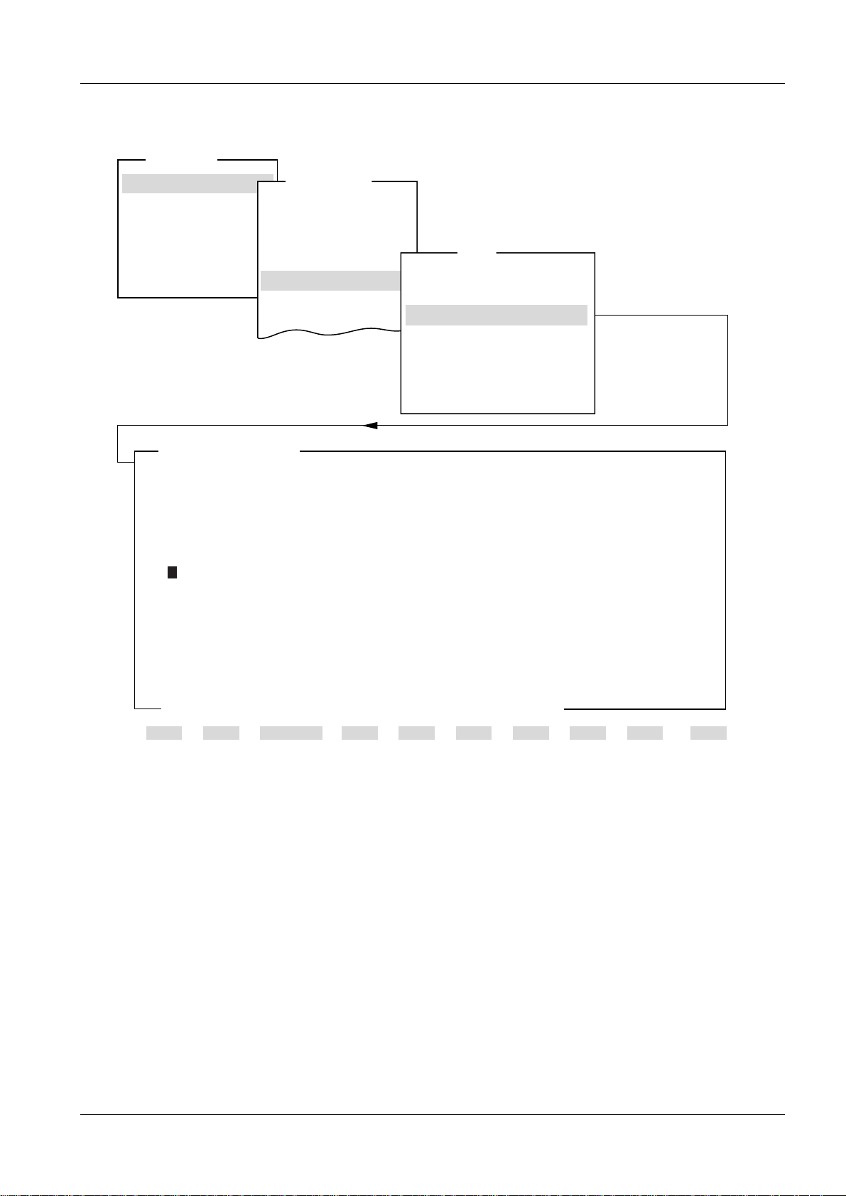
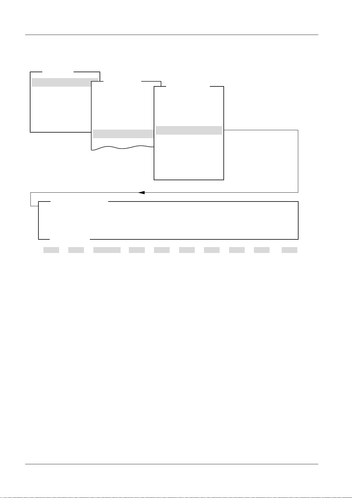
Configuration 2
System type 2
2 - 1
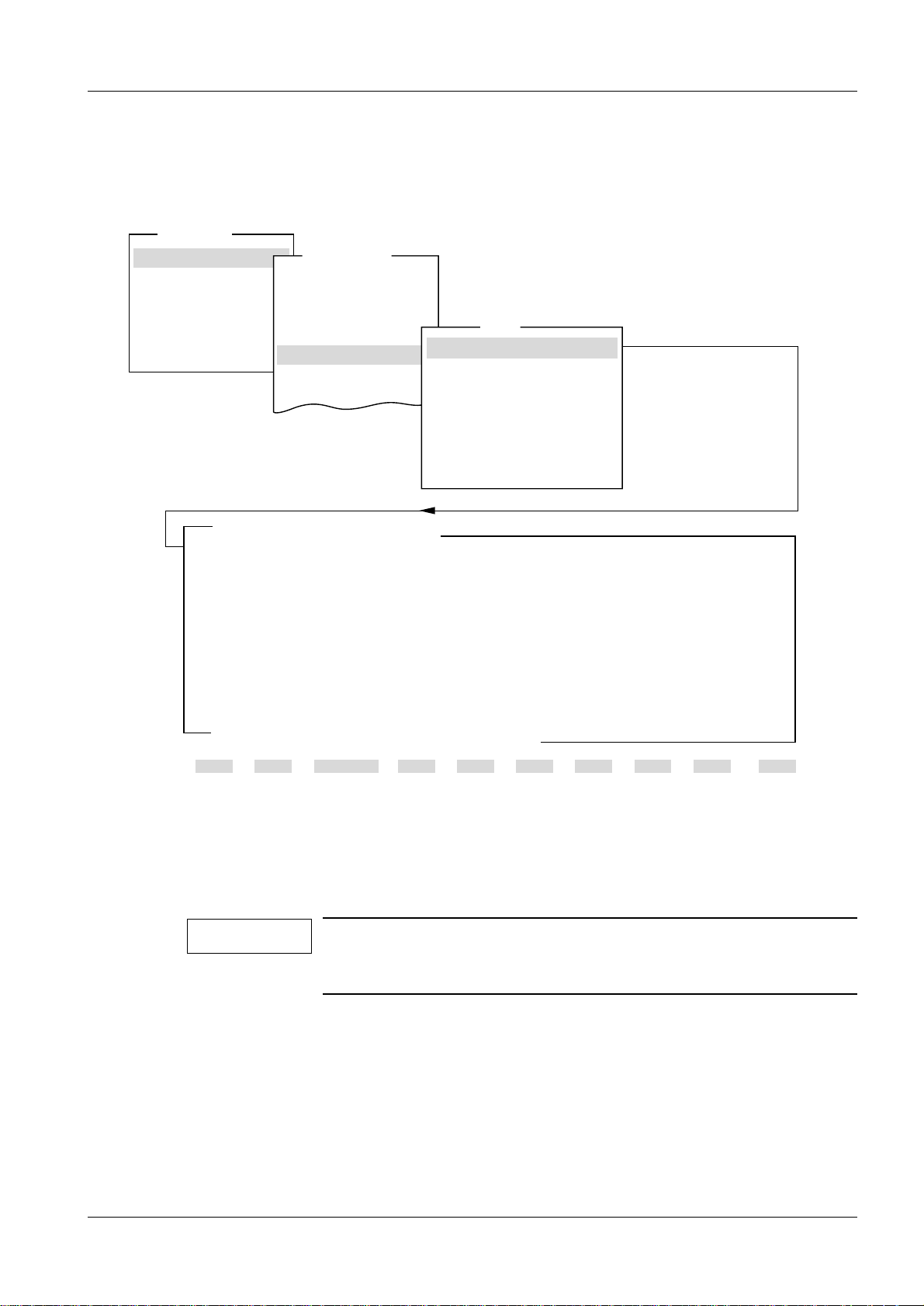
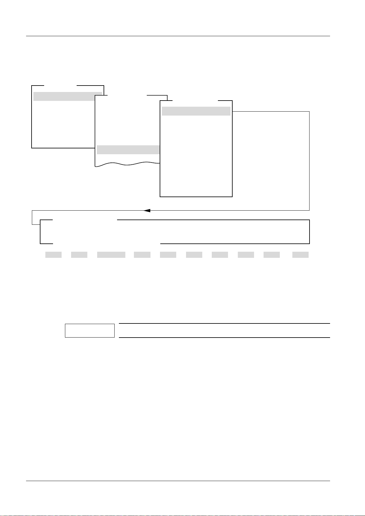
Fig. 1
System type indicates type of stand, gener ator and control panel. Collimator indicates
type of collimator in the stand. Collimator choice (Automatic or Manual) is valid only for
MAMMOMAT 1000.
When MAMMOMAT 1000 is selected, the tungsten anode is automatically deselected,
and furthermore, the Anode menu cannot be selected.
Siemens-Elema AB Register 5 SPB7-230.114.03 Page 1 of 64 M1000/3000/3000 Nova
Solna, Sweden Rev. 05 02.03 SPS-UD Service Program
Page 12
2 - 2 Adjustment and Service PC Programs
Normal mode
Test DUEP Communic.
Backup
Quit
Main menu
Service
Configuration
Save configuration file
Miscellaneous
Filament
Configuration
Show configuration file
Anode
Tungsten anode
1 Help 2 Save 3 45678910Quit
System type
AEC
Enable
NOTE: When changing the anode selection, always check the power setting.
<ESC> to exit, <space to toggle entry>
Anode
MAM00585
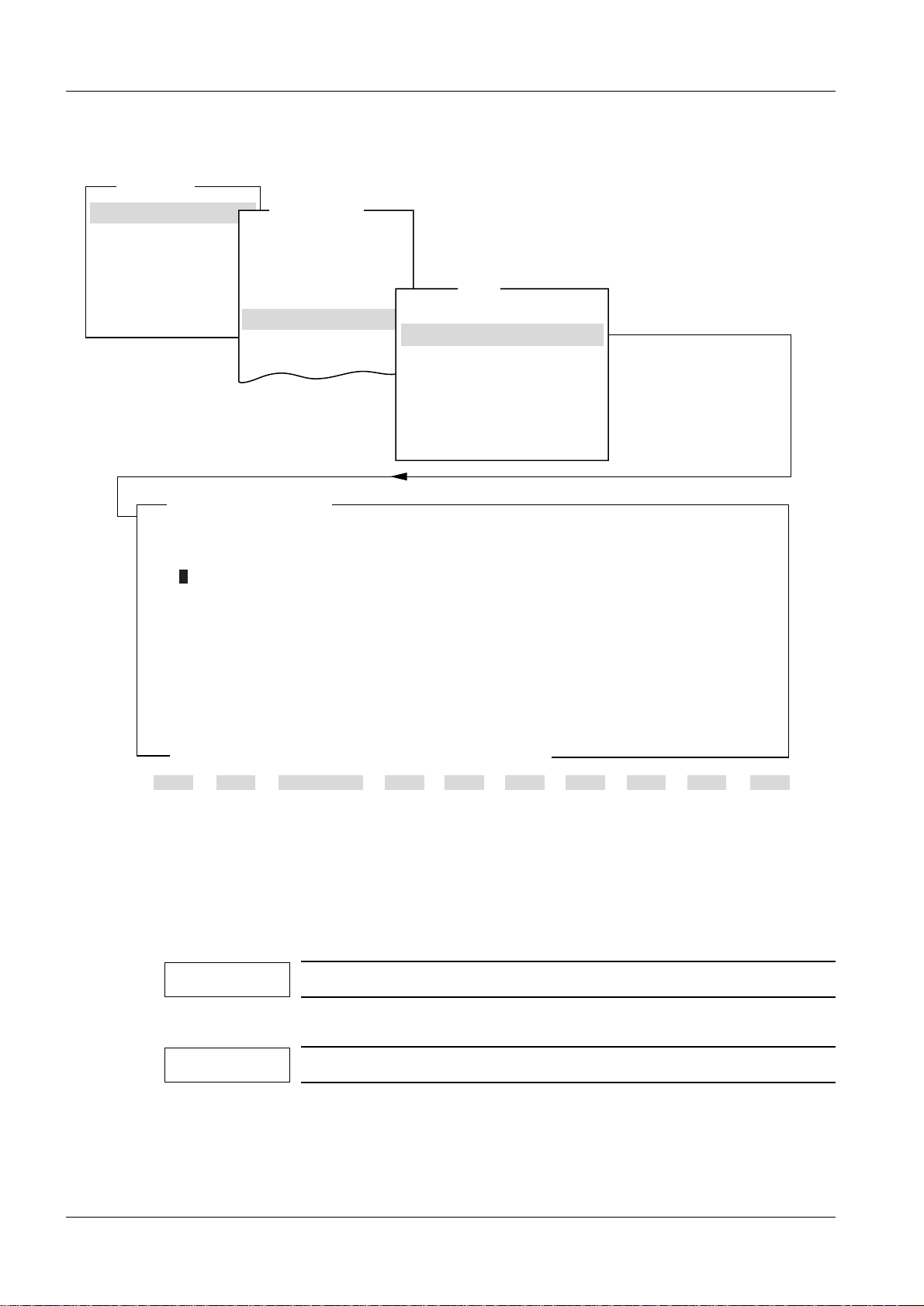
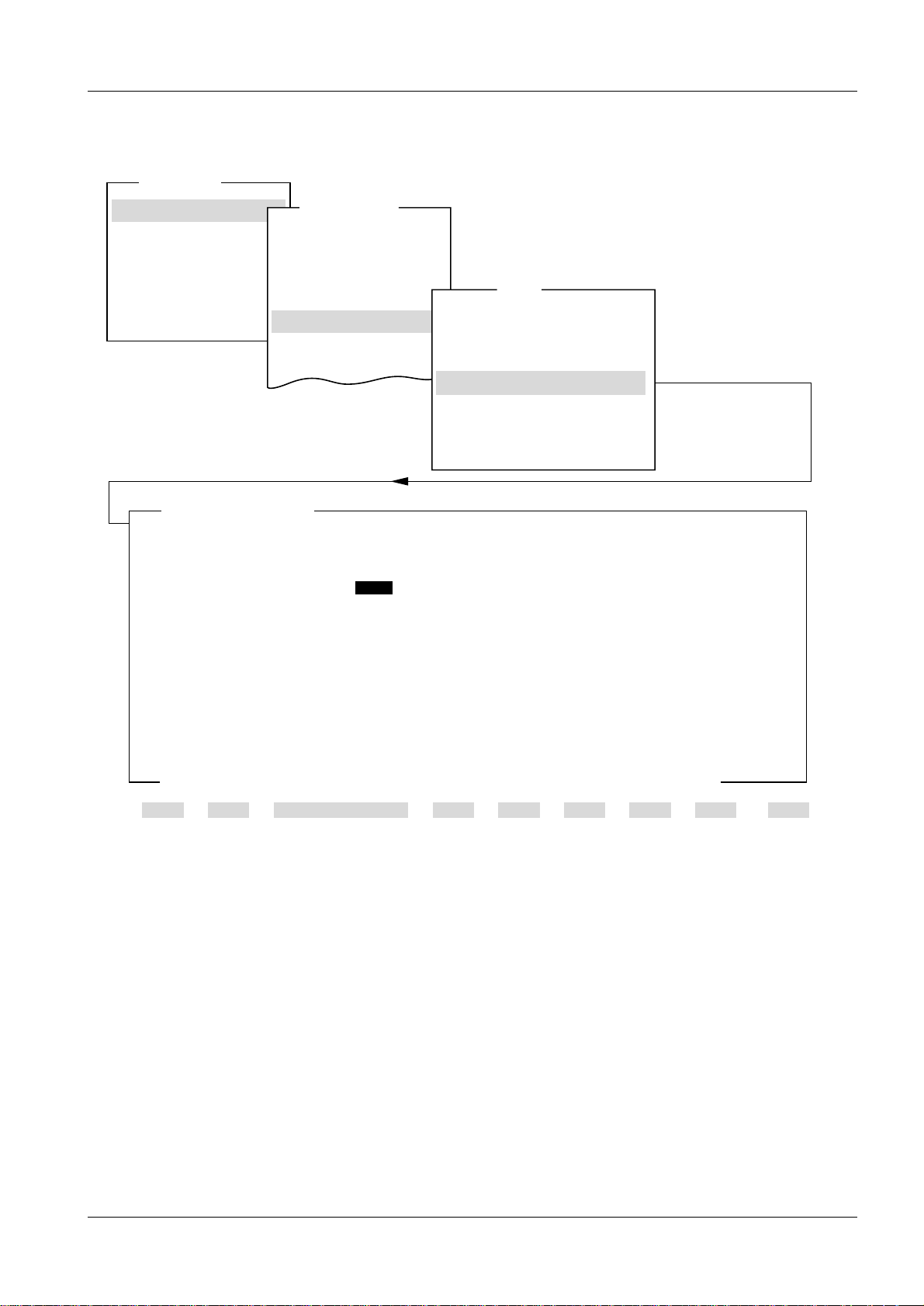
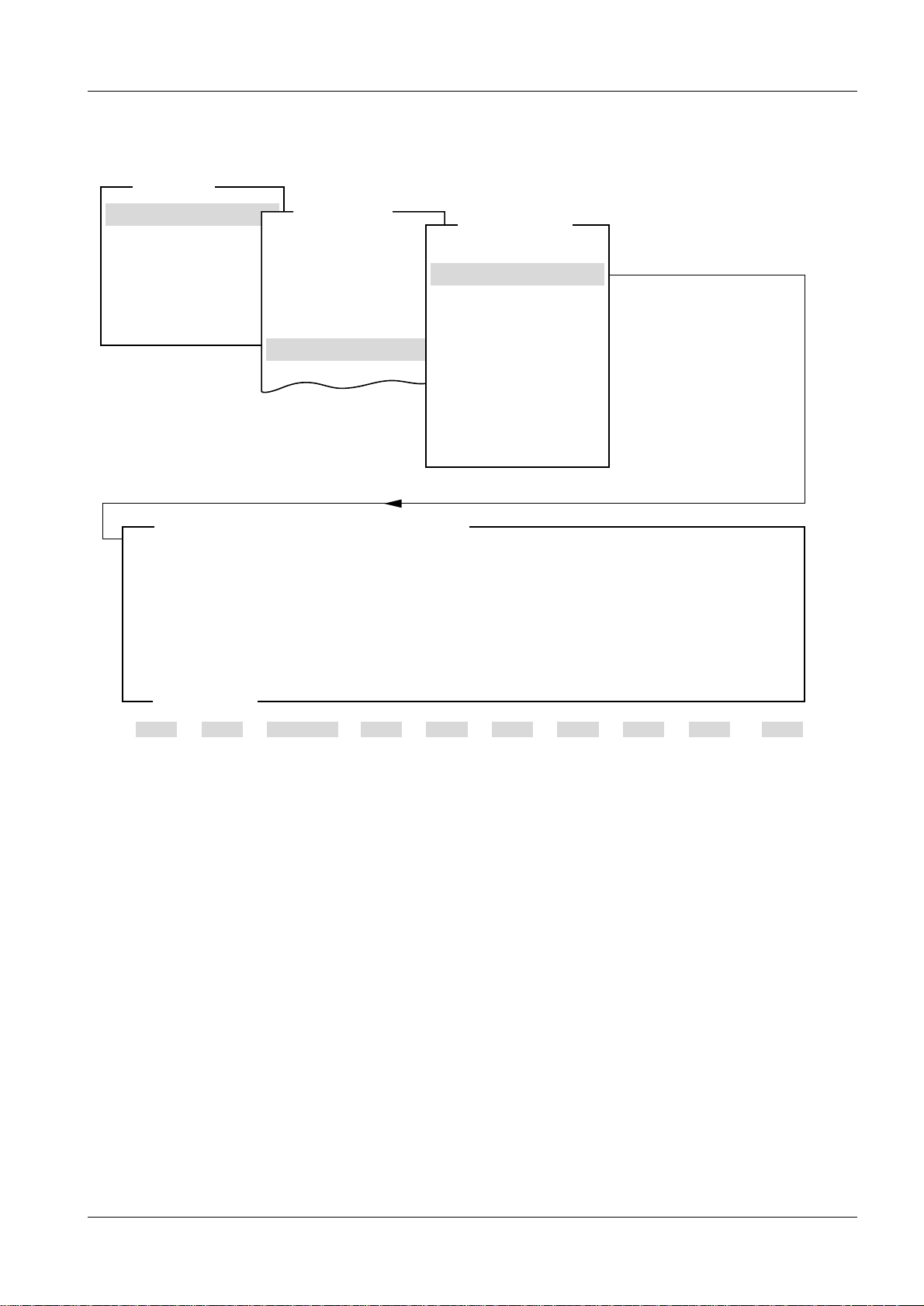
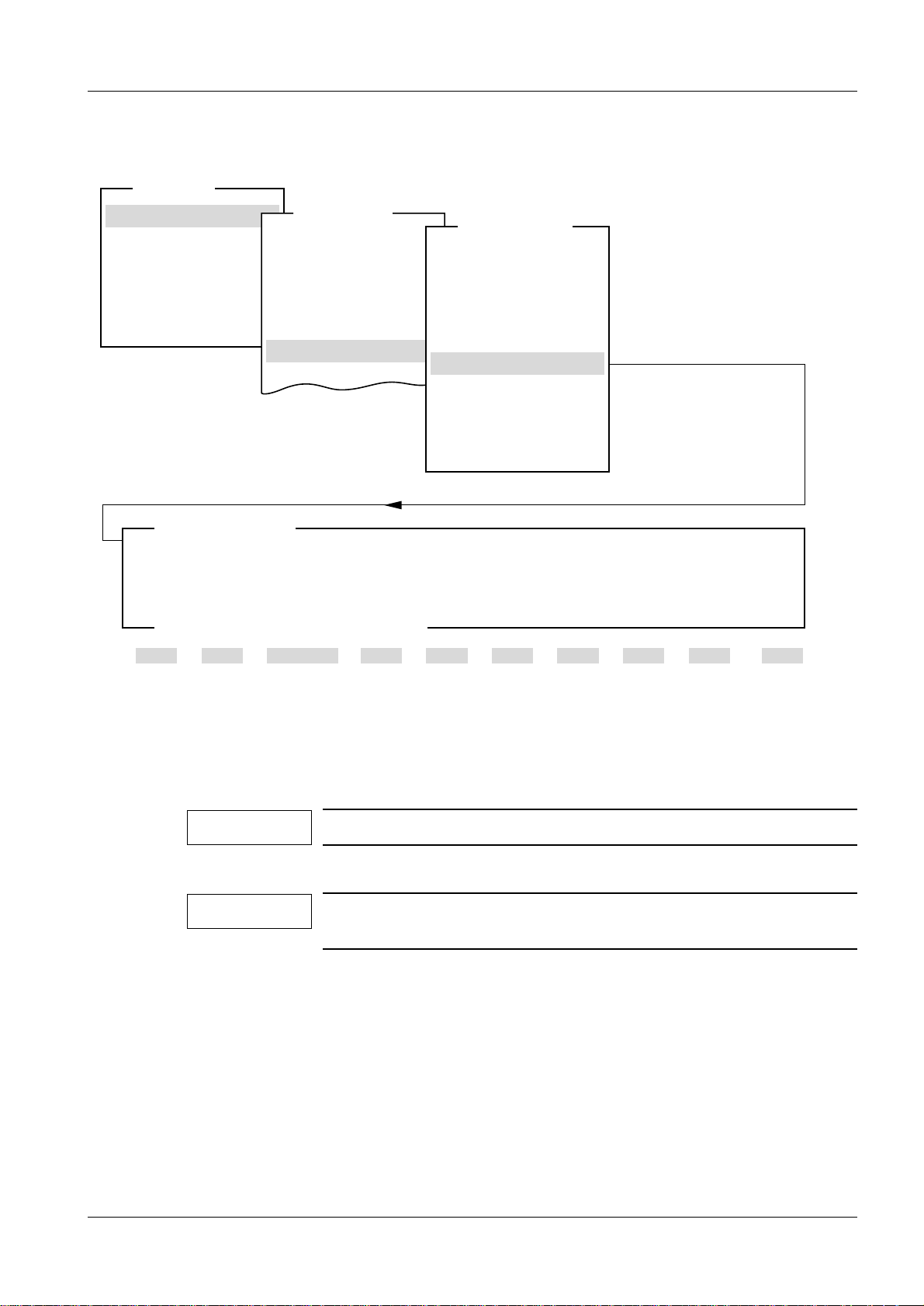
Anode 2
Fig. 2
Activation and deactivation of the tungsten anode. When deactivated, it will not be
possible to select the W/Rh alternative on the control panel.
NOTE
This menu is not selectabl e when the syst em typ e is set t o M1000.
M1000/3000/3000 Nova Register 5 SPB7-230.114.03 Page 2 of 64 Siemens-Elema AB
Service Program Rev. 05 02.03 SPS-UD Solna, Sweden
Page 13
Adjustment and Service PC Programs 2 - 3
Normal mode
Test DUEP Communic.
Backup
Quit
Main menu
Service
Configuration
AEC
Miscellaneous
Filament
Configuration
Show configuration file
1 Help 2 3 4 5 6 7 8 9 10 Quit
System type
Save configuration file
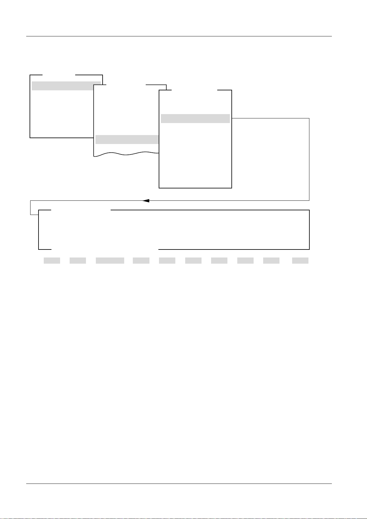
Show file mammo.cfg
System M3000 Tungsten Anode
Power
Molly large focus 3.75 kW Tungsten large focus 4.70 kW
Molly small focus 0.70 kW Tungsten small focus 0.85 kW
Filament current
Molly large focus 6500 mA Tungsten large focus 6500 mA
Molly small focus 6500 mA Tungsten small focus 6500 mA
Power supply OFF
Sensitivity Mo/Mo Mo/Rh W/Rh
Grid 18x24 (H/D) 0/0 0/0 0/0
Grid 24x30 (H/D) 0/0 0/0 0/0
No Grid 18x24 (H/D) 0/0 0/0 0/0
No Grid 24x30 (H/D) 0/0 0/0 0/0
Mag 1.5 (H/D) 0/0 0/0 0/0
Mag 1.8 (H/D) 0/0 0/0 0/0
Stereo (H/D) 0/0 0/0 0/0
Optimized compression
OPCOMP 18*24, 24*30 / OFF
mag 15, 18
/ OFF
Auto limits P1 30mm P2 45mm P3 60mm
Anode
ENABLED
Collimator AUTOMATIC
MAM00771
Any key to continue
Sensitivity correction (H/D) 0 0
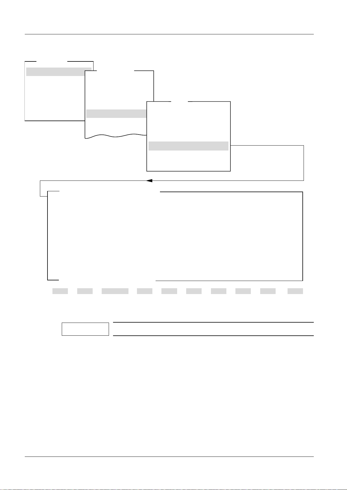
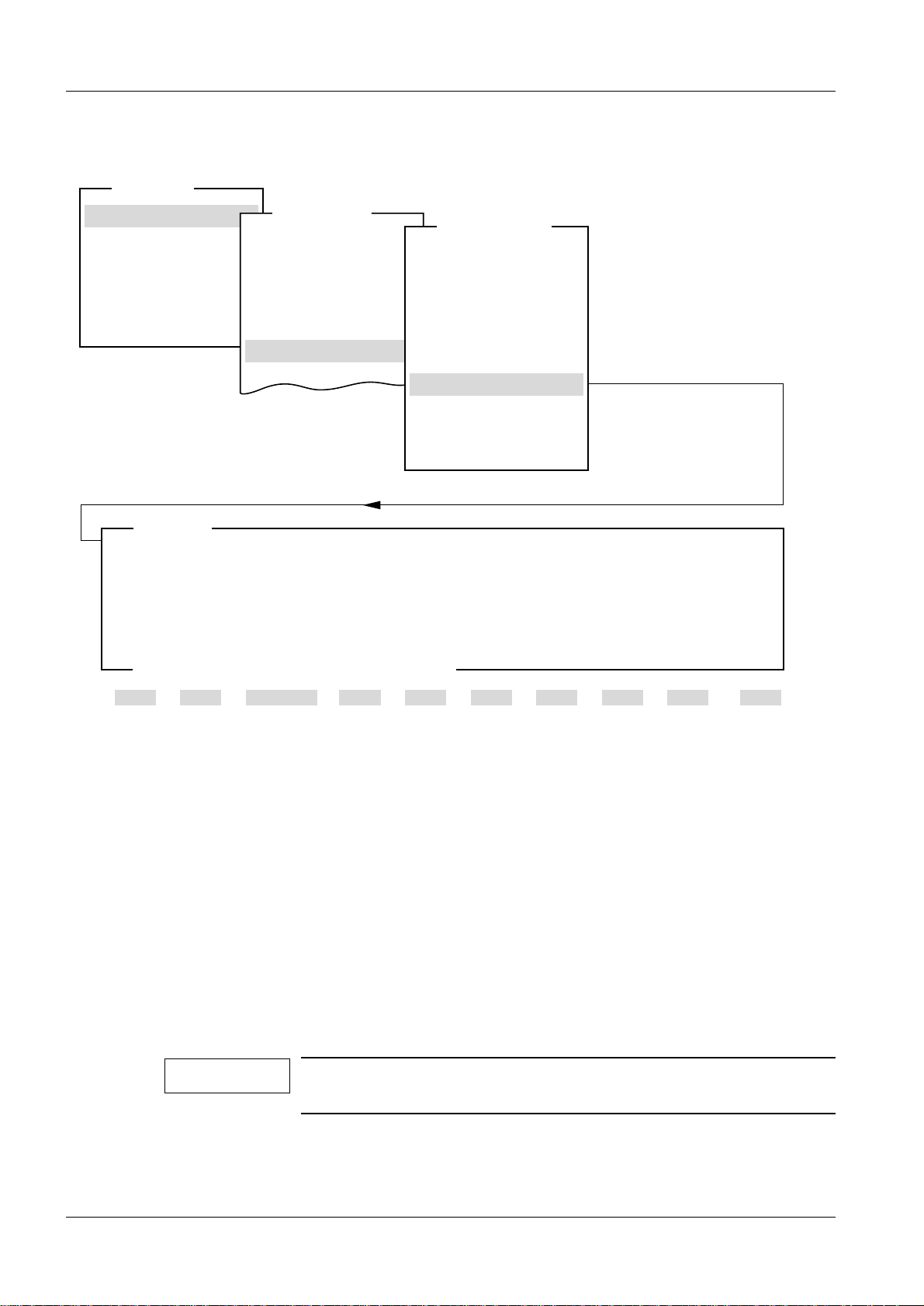
Show configuration file 2
Fig. 3
Siemens-Elema AB Register 5 SPB7-230.114.03 Page 3 of 64 M1000/3000/3000 Nova
Solna, Sweden Rev. 05 02.03 SPS-UD Service Program
This menu displa ys the system configuration as stored in the “mammo.cfg” file.
The file must be stored before it is possible to show it, see "Save configuration file" on
Page 2 - 4.
NOTE
All data are examples and may vary for the unit in question.
Page 14
2 - 4 Adjustment and Service PC Programs
Normal mode
Test DUEP Communic.
Backup
Quit
Main menu
Service
Configuration
AEC
Miscellaneous
Filament
Configuration
Show configuration file
1 Help 2 Save 3 4 5 6 7 8 9 10 Quit
System type
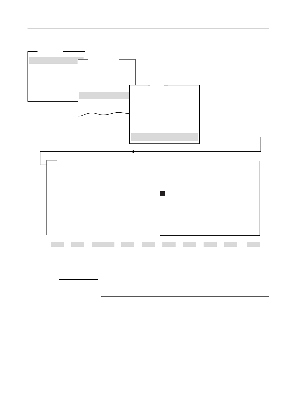
Save configuration file
Save configuration -> mammo.cfg
Anode
MAM00772
<ESC> to exit, <F2> save list in file mammo.cfg
System M3000 Tungsten Anode
Power
Molly large focus 3.75 kW Tungsten large focus 4.70 kW
Molly small focus 0.70 kW Tungsten small focus 0.85 kW
Filament current
Molly large focus 6500 mA Tungsten large focus 6500 mA
Molly small focus 6500 mA Tungsten small focus 6500 mA
Power supply
Sensitivity (H/D) 0 0
OFF
Sensitivity correction Mo/Mo Mo/Rh W/Rh
Grid 18x24 (H/D) 0/0 0/0 0/0
Grid 24x30 (H/D) 0/0 0/0 0/0
No Grid 18x24 (H/D) 0/0 0/0 0/0
No Grid 24x30 (H/D) 0/0 0/0 0/0
Mag 1.5 (H/D) 0/0 0/0 0/0
Mag 1.8 (H/D) 0/0 0/0 0/0
Stereo (H/D) 0/0 0/0 0/0
Optimized compression
OPCOMP 18*24, 24*30 / mag 15, 18 OFF OFF
Auto limits
P1 30mm P2 45mm P3 60mm
ENABLED
Collimator AUTOMATIC
/
Save configuration file 2
Fig. 4
This menu is used for storing information about the system configurat ion in the
“mammo.cfg” file. Pres s <F 2 > to save the file.
If the service program was started from a floppy disk, the file will be stored on flopp y. If the
service program was started from the hard disk, the file will be stored on hard disk.
M1000/3000/3000 Nova Register 5 SPB7-230.114.03 Page 4 of 64 Siemens-Elema AB
Service Program Rev. 05 02.03 SPS-UD Solna, Sweden
Page 15
Adjustment and Service PC Programs 2 - 5
AEC - Reset installation parameters
1
Help 2 Save 3 4 5 6 7 8 9 10 Quit
<ESC> to exit, <F2> to reset installation parameters
MAM00540
By pressing <F2> You will reset the AEC installation parameters.
All existing sensitivity settings and results
from performed detector normalization, including
installed correction tables, will be lost.
Normal mode
Test DUEP Communic.
Backup
Quit
Main menu
Service
Configuration
Save configuration file
Miscellaneous
Filament
Configuration
Show configuration file
System type
AEC
Reset installation parameters
Copy H to D
Copy D to H
Sensitivity
Reset installation parameters
Detector normalization
AEC Correction tables
Sensitivity correction
AEC
Anode
AEC 2
AEC -> Reset installation parameters
This menu is used for setting AEC installation parameters to default values and for
erasure of installed AEC Correction tables in the MAMMOMAT.
NOTE
It is not necessary to use this procedure with exchange of
detector. It must be used with exchange of D701 i f AEC backup is
not available.
Siemens-Elema AB Register 5 SPB7-230.114.03 Page 5 of 64 M1000/3000/3000 Nova
Solna, Sweden Rev. 05 02.03 SPS-UD Service Program
Page 16
2 - 6 Adjustment and Service PC Programs
Detector normalization
1 Help 2 Save 3 4 5 6 7 8 9 10 Quit
<ESC> to exit, <F2> to save, <F3> to measure dose rate
MAM00775
Exp support
Normal mode
Test DUEP Communic.
Backup
Quit
Main menu
Service
Configuration
Save configuration file
Miscellaneous
Filament
Configuration
Show configuration file
System type
AEC
Reset installation parameters
Detector normalization
AEC Correction tables
Sensitivity correction
Copy H to D
Copy D to H
Sensitivity
AEC
Anode
Wing 1 Wing 2
Exp. Dose rate Exp. Dose rate
1 430.6 1
---------
2
---------
2
---------
3
---------
3
---------
Average dose rate
---------
Average dose rate
---------
Normalization factor W1:
---------
Normalization factor W2:
---------
AEC -> Detector normalization
Fig. 5
This menu is used for normalization of the AEC detector in available wing. Values for Normalization factors are calculated and stored i n the AEC.
Exposure results are stored in the result file “detnorm.txt” on the backup floppy.
NOTE
NOTE
All data are examples and may v ary for the unit in question.
Wing 1 is not selectable when the system type is set to M1000.
M1000/3000/3000 Nova Register 5 SPB7-230.114.03 Page 6 of 64 Siemens-Elema AB
Service Program Rev. 05 02.03 SPS-UD Solna, Sweden
Page 17
Adjustment and Service PC Programs 2 - 7
MAM00616
1 Help 2 Save Exp support3 45678910Quit
MAM00767
<ESC> to exit, <F2> to save, <F3> to measure dose rate
Wing 1 Wing 2
Exp. Dose rate Exp. Dose rate
1
---------
1
---------
2
---------
2
---------
3
---------
3
---------
Average dose rate:
---------
Average dose rate:
---------
Normalization factor W1:
---------
Normalisation factor W2:
---------
Fig. 6 Average dose rate: Out of the three obtained values, the one that differs the most is
ignored. The average dose rate is then calculated based on the remaining two values.
Normalization factor: The value of the normalization factor should be between 512 and
2048. If not, ensure that the correct object table and AEC calibration plexi have been
Perform detector normalization:
• after replacement of an AEC detector for that wing.
• after replacement of D701 and restoring from backup of AEC and c orrection tables. If two
wing system, normalize both detectors.
• after AEC reset installation parameters. In a two wi ng M3000 normalize both detectors.
When performing detector normalizations:
• The detector is to be in chestwall position.
• The AEC calibration plexi (part no. 65 61 240) must extend at l east 10 mm beyond the
chestwall edge of the table and be center ed.
The following e xposures are to be made:
• with no cassette or film
• with the very same AEC calibration plexi and object table.
It is strongly suggested that y ou use a Grid 18x24 object table (Bucky).
1. Make sure a backup floppy is inserted.
2. In <Mainmenu> select <Configuratio n>, <AEC> and
<Detector normalization>.
Siemens-Elema AB Register 5 SPB7-230.114.03 Page 7 of 64 M1000/3000/3000 Nova
Solna, Sweden Rev. 05 02.03 SPS-UD Service Program
3. Bring the detector to be normalize d into the x-ray field.
Page 18
2 - 8 Adjustment and Service PC Programs
Please put x cm of Plexi
on the object table.
Perform an exposure and
press <ENTER> when ready
or <ESC> to cancel.
<ENTER> - ok / <ESC> - cancel
MAM00728
Calibration exposure
1 Help 2 Save Exp support3 45678910Quit
MAM00769
<ESC> to exit, <F2> to save, <F3> to perform exposure
Mo/Rh, wing 2
Exp. 1
Dose rate
---------
1 Help 2 Save Exp support3 45678910Quit
MAM00768
<ESC> to exit, <F2> to save, <F3> to measure dose rate
Wing 1 Wing 2
Exp. Dose rate Exp. Dose rate
1 213,18 1 204.99
2 213,92 2 205.72
3 215,04 3 204.85
Average dose rate: 213,55 Average dose rate: 204,92
Normalization factor W1: 1067
Normalization factor W2: 997
Fig. 7 Example of the final result of a wing calibration
4. Place the cursor by one of the exposures of the wing in use and press <F3> to
start the exposure procedure.
5. Follow the instructions in the message box.
6. After pressing <ENTER> the dialog Calib ration exposure appears. The Dose rate
should now have a value. Save the value with <F2>.
7. Repeat steps 4 to 6 for the other two exposur es, for the wing in question.
M1000/3000/3000 Nova Register 5 SPB7-230.114.03 Page 8 of 64 Siemens-Elema AB
Service Program Rev. 05 02.03 SPS-UD Solna, Sweden
8. If only one detector is to be normali zed, save the values by pressing <F2>.
Otherwise proceed to steps number 9 and 10.
9. Bring the other wing into the x-ra y field. Use the same object table.
10. Repeat steps 4 to 6 for the other three exposures. Save the values on floppy by
pressing <F2>.
Page 19
Adjustment and Service PC Programs 2 - 9
AEC correction tables
1 Help 2 Save 3 4 5 6 78910Quit
MAM00542
Cal
Normal mode
Test DUEP Communic.
Backup
Quit
Main menu
Service
Configuration
Save configuration file
Miscellaneous
Filament
Configuration
Show configuration file
System type
Reset installation parameters
Detector normalization
AEC Correction tables
Sensitivity correction
Copy H to D
Copy D to H
Sensitivity
AEC
AEC
Anode
<ESC> to exit, <F2> to install new table, <F3> to calibrate existing
Anode/Filter Speed ID Calibrated
Mag Grid No grid Stereo
Mo/Mo H 1001 No Yes No No
Mo/Mo D
----
--- --- --- --Mo/Rh H 1002 No No No No
Mo/Rh D
----
--- --- --- --W/Rh H 1003 No No No No
W/Rh D
----
--- --- --- ---
Existing tables in the AEC:
AEC -> Correction tables
Fig. 8
Siemens-Elema AB Register 5 SPB7-230.114.03 Page 9 of 64 M1000/3000/3000 Nova
Solna, Sweden Rev. 05 02.03 SPS-UD Service Program
This menu is used for:
• Installation of correction tables (F2).
• Calibration of correction tables (F3), in cluding rough setting of sens itivity correction.
The AEC uses one correction table for each Anode/Filter/Speed combination. Each correction table has separ ate co rrections for each object t abl e group (Ma gnificat ion, Grid, No
grid and Stereo). When pressing <F2> a dialog box will appear, in which the ID of the correction table to be instal led (from floppy disk) should be entered. When the transaction of
the correction table to the AEC is finishe d, the program will automatically go on to the calibration process.
To enter the calibration process without having installed new correction tables, press
<F3>. When pressing <F3> correction tables previously installed will be loaded from the
AEC. See “Installation and Start-Up Instructions” for further information.
Page 20

2 - 10 Adjustment and Service PC Programs
During the calibration process of a correction table calibration reference data is fetched
from a calibration file (“calxxxx.txt”, in which the four x:es represent the ID number). The
ID of this file is the same as f or the corr ection tab l e in use and is located on the floppy containing the AEC correction tables (original AEC correction tables shall normally be copied
from the floppy "AEC correction tables" to a backup floppy). The backup floppy m ust be
inserted during the entire calibration.
When pressing <F2> exposure data f rom the cal ibration process is stored in a result file,
e.g. “mrgh.txt”, on thi s floppy. In “mrgh.txt” the first letter rep resents t ype of anode (“m” fo r
molly or “w” for wolfram/tungsten), the second represents type of filter (“m” for molly or “r”
for rhodium), the third represents the ki nd of object table (“g” for grid, “n” for no grid, “s” for
stereo or “m” for magnification) and the fourth represents the speed (“h” for high or “d” for
detailed).
M1000/3000/3000 Nova Register 5 SPB7-230.114.03 Page 10 of 64 Siemens-Elema AB
Service Program Rev. 05 02.03 SPS-UD Solna, Sweden
Page 21
Adjustment and Service PC Programs 2 - 11
Sensitivity correction
1 Help 2 Save 3 5 6 7 8 9 10 Quit
Valid entries from -120 to 120 in 1/8 E.P. (+/-15 E.P.)
<ESC> to exit, <TAB> move to next entry field, <F2> to save, <F3> exp support
MAM00537
Exp support
HD
Mo/Mo Mo/Rh W/Rh Mo/Mo Mo/Rh W/Rh
Grid 18x24 0 00 000
Grid 24x30 0 0 0 0 0 0
No grid 18x24 0 0 0 0 0 0
No grid 24x30 0 0 0 0 0 0
Magnification 1.5 0 0 0 0 0 0
Magnification 1.8 0 0 0 0 0 0
Stereo 0 0 0 0 0 0
Normal mode
Test DUEP Communic.
Backup
Quit
Main menu
Service
Configuration
Save configuration file
Miscellaneous
Filament
Configuration
Show configuration file
System type
Reset installation parameters
Detector normalization
AEC Correction tables
Sensitivity correction
Copy H to D
Copy D to H
Sensitivity
AEC
AEC
Anode
AEC -> Sensitivity correction
Fig. 9
This menu is used for setting the sensitivity correction of the AEC channel for all object
table types, combinations of anode/filter and for speed H and D respectively.
By pressing <F3> the correct exposure parameters will be set for the generator and a
message box appears, showing which Plexiglas thickness should be used during exposure. A flopp y containing the AEC correction tables must be inserted since access to the
calibration file (“cal xxxx.txt”) is necessary when using the function <F3> exp support.
Values from -120 to 120 can be entered in 1/8 exposure points.
Also see “Installation and Start-Up Instructions”.
Siemens-Elema AB Register 5 SPB7-230.114.03 Page 11 of 64 M1000/3000/3000 Nova
Solna, Sweden Rev. 05 02.03 SPS-UD Service Program
Page 22
2 - 12 Adjustment and Service PC Programs
AEC - Copy settings between speeds
1
Help 2 Copy 3 4 5 6 7 8 9 10 Quit
<ESC> to exit, <F2> to copy H -> D
MAM00651
By pressing <F2> You will copy
all settings for speed H to speed D.
All existing settings for speed D will be overwritten.
Normal mode
Test DUEP Communic.
Backup
Quit
Main menu
Service
Configuration
Save configuration file
Miscellaneous
Filament
Configuration
Show configuration file
System type
AEC
Reset installation parameters
Copy H to D
Copy D to H
Sensitivity
Reset installation parameters
Detector normalization
AEC Correction tables
Sensitivity correction
AEC
Anode
AEC -> Copy H to D
This menu is used for copyi ng AEC data from speed H to speed D.
NOTE
Alternative Copy D to H works similarly to Copy H to D.
M1000/3000/3000 Nova Register 5 SPB7-230.114.03 Page 12 of 64 Siemens-Elema AB
Service Program Rev. 05 02.03 SPS-UD Solna, Sweden
Page 23
Adjustment and Service PC Programs 2 - 13
AEC - Sensitivity
1
Help 2 Save 3 4 5 6 78910Quit
<ESC> to exit, <TAB> move to next entry field
MAM00652
HD
Sensitivity 0 0
valid entries from -64 to 64 in 1/8 E.P. (+ / - 8 E.P.)
Normal mode
Test DUEP Communic.
Backup
Quit
Main menu
Service
Configuration
Save configuration file
Miscellaneous
Filament
Configuration
Show configuration file
System type
AEC
Reset installation parameters
Copy H to D
Copy D to H
Sensitivity
Reset installation parameters
Detector normalization
AEC Correction tables
Sensitivity correction
AEC
Anode
AEC -> Sensitivity
This dialog indicates the sensitivity of the AEC for speed H and speed D respectively.
Values from -64 to 64 can be entered in 1/8 exposure points.
NOTE
If only one type of film-screen-combination is used, set both values for H and D to the same level.
Also see “Installation and Start-Up Instructions”.
Siemens-Elema AB Register 5 SPB7-230.114.03 Page 13 of 64 M1000/3000/3000 Nova
Solna, Sweden Rev. 05 02.03 SPS-UD Service Program
Page 24
2 - 14 Adjustment and Service PC Programs
Normal mode
Test DUEP Communic.
Backup
Quit
Main menu
Service
Configuration
Save configuration file
Filament
Configuration
Show configuration file
Anode
Dynamic learn filament
Switch is ON
1 Help 2 Save 3 45678910Quit
System type
Miscellaneous
Reduction of power
AEC
Printer
Miscellaneous
Power supply
Potentiometer check
Panel programming
Auto limits
Cassette loaded check
Illumination time
Software version info
DLF switch
<ESC> to exit, <space> to toggle entry
MAM00543
Miscellaneous 2
Miscellaneous -> DLF switch
Fig. 10
Activation and deac tiv ation of the filament current adapt ation. When acti v ated, the ad aptation takes place after a total of ten exposures has been made with the actual focus, if the
deviation of the average value from the nominal value is not within -15% to + 5%.
NOTE
Without any exceptional reason, the DLF-switch shall be “ON”.
M1000/3000/3000 Nova Register 5 SPB7-230.114.03 Page 14 of 64 Siemens-Elema AB
Service Program Rev. 05 02.03 SPS-UD Solna, Sweden
Page 25
Adjustment and Service PC Programs 2 - 15
Normal mode
Test DUEP Communic.
Backup
Quit
Main menu
Service
Configuration
Save configuration file
Filament
Configuration
Show configuration file
Anode
Reduction of power depending on line quality
Tube is P40MoW
1 Help 2 Save 3 45678910Quit
System type
Miscellaneous
Reduction of power
AEC
Miscellaneous
Power supply
Potentiometer check
Panel programming
Auto limits
Cassette loaded check
Illumination time
Software version info
DLF switch
Select nominal line voltage
240 V <-- with cursor keys and <Enter>
Type in line impedance
Power is 4.70 kW TUNGSTEN
3.75 kW MOLLY
<ESC> to exit
MAM00544
Printer
Miscellaneous -> Reduction of power
Fig. 11
Calculates the maximum powe r allowed with regard to nominal voltage and line impedance.
Select the line voltage and type i n the line impedance y ou ha v e measured. The process or
will calculate the pow er and will indic ate when the power must be reduced because of the
line impedance.
Finally press <F2> to save.
Siemens-Elema AB Register 5 SPB7-230.114.03 Page 15 of 64 M1000/3000/3000 Nova
Solna, Sweden Rev. 05 02.03 SPS-UD Service Program
Page 26
2 - 16 Adjustment and Service PC Programs
Normal mode
Test DUEP Communic.
Backup
Quit
Main menu
Service
Configuration
Save configuration file
Filament
Configuration
Show configuration file
Printer type selection
Actual setting
1 Help 2 Save 3 45678910Quit
System type
Miscellaneous
Reduction of power
AEC
Printer
Power supply
Potentiometer check
Panel programming
Auto limits
Cassette loaded check
Illumination time
Software version info
DLF switch
no print
<ESC> to exit, <space> to toggle entry
Anode
Miscellaneous
MAM00546
Miscellaneous -> Printer
Fig. 12
Select no print, RS 232C or PC print.
RS 232C is used when the printer is connected directly to the generat or.
PC print is used when the printer is connected to the system via a PC that is con nected to
the generator.
M1000/3000/3000 Nova Register 5 SPB7-230.114.03 Page 16 of 64 Siemens-Elema AB
Service Program Rev. 05 02.03 SPS-UD Solna, Sweden
Page 27
Adjustment and Service PC Programs 2 - 17
Normal mode
Test DUEP Communic.
Backup
Quit
Main menu
Service
Configuration
Save configuration file
Filament
Configuration
Show configuration file
Power supply
Switch is
1 Help 2 Save 3 45678910Quit
System type
Miscellaneous
Reduction of power
AEC
Printer
Miscellaneous
Power supply
Potentiometer check
Panel programming
Auto limits
Cassette loaded check
Illumination time
Software version info
DLF switch
<ESC> to exit, <space> to toggle entry
Anode
OFF
MAM00547
Miscellaneous -> Power supply
Fig. 13
Indicates whether the MAMMOMAT is powered by an external power supply (e.g. Power
Aid) or not.
Siemens-Elema AB Register 5 SPB7-230.114.03 Page 17 of 64 M1000/3000/3000 Nova
Solna, Sweden Rev. 05 02.03 SPS-UD Service Program
Page 28
2 - 18 Adjustment and Service PC Programs
Normal mode
Test DUEP Communic.
Backup
Quit
Main menu
Service
Configuration
Save configuration file
Filament
Configuration
Show configuration file
Potentiometer check
A/D value
1 Help 2 Save 3 45678910Quit
System type
Miscellaneous
Reduction of power
AEC
Printer
Miscellaneous
Power supply
Potentiometer check
Panel programming
Auto limits
Cassette loaded check
Illumination time
Software version info
DLF switch
032A
<ESC> to exit
Anode
MAM00548
Miscellaneous -> Potentiometer check
Fig. 14
Sampled calibration v alue for the return current through the four potentiometers “preset
force”, “preset angle”, “thickness” and “angle”. This return current is continuously monitored by the system. Should the return current deviate too much from the calibration
value, this is probably due to a faulty potentiometer or due to a contact failure with one of
the potentiometers, which results in error code 825 or 826.
M1000/3000/3000 Nova Register 5 SPB7-230.114.03 Page 18 of 64 Siemens-Elema AB
Service Program Rev. 05 02.03 SPS-UD Solna, Sweden
Page 29
Adjustment and Service PC Programs 2 - 19
Normal mode
Test DUEP Communic.
Backup
Quit
Main menu
Service
Configuration
Save configuration file
Filament
Configuration
Show configuration file
Panel programming
Switch is
1 Help 2 Save 3 45678910Quit
System type
Miscellaneous
Reduction of power
AEC
Printer
Miscellaneous
Power supply
Potentiometer check
Panel programming
Auto limits
Cassette loaded check
Illumination time
Software version info
DLF switch
ON
<ESC> to exit, <space> to toggle entry
Anode
MAM00549
Miscellaneous -> Panel programming
Fig. 15
Activation and deactivation of the Memory button on the control panel, making it possible
to change the program settings for the four programs.
With the switch “OFF”, any change of data is blocked.
NOTE
NOTE
Should be switched “OFF” only if customer demands.
This menu is not selectable with software V4.1 when the system
type is set to M1000.
Siemens-Elema AB Register 5 SPB7-230.114.03 Page 19 of 64 M1000/3000/3000 Nova
Solna, Sweden Rev. 05 02.03 SPS-UD Service Program
Page 30
2 - 20 Adjustment and Service PC Programs
Normal mode
Test DUEP Communic.
Backup
Quit
Main menu
Service
Configuration
Save configuration file
Filament
Configuration
Show configuration file
Auto limits
Program 1
1 Help 2 Save 3 45678910Quit
System type
Miscellaneous
Reduction of power
AEC
Printer
Miscellaneous
Power supply
Potentiometer check
Panel programming
Auto limits
Cassette loaded check
Illumination time
Software version info
DLF switch
30 mm
Program 2 45 mm
Program 3 60 mm
Auto limits
Valid entries from 0 to 180 mm
<ESC> to exit, <TAB> move to next entry field
Anode
MAM00773
Miscellaneous -> Auto limits
Fig. 16
Set the upper thickness limits for the programs 1-3.
Program 1 has a lower limit of 0 and Program 4 has a higher limit of 180 mm.
Supposing the above used values are stored in auto mode:
• The program key P1 is automatically selected with a compression thick ness between 0
and 30 mm.
• The program key P2 is automatically selected with a compression thick ness between 31
and 45 mm.
• The program key P3 is automatically selected with a compression thick ness between 46
and 60 mm.
• The program key P4 is automatically selected with a compression thi ckness more than
60 mm.
NOTE
M1000/3000/3000 Nova Register 5 SPB7-230.114.03 Page 20 of 64 Siemens-Elema AB
Service Program Rev. 05 02.03 SPS-UD Solna, Sweden
This menu is not selectable with software V4.1 when the system
type is set to M1000.
Page 31

Adjustment and Service PC Programs 2 - 21
Normal mode
Test DUEP Communic.
Backup
Quit
Main menu
Service
Configuration
Save configuration file
Filament
Configuration
Show configuration file
Cassette loaded check
Switch is
1 Help 2 Save 3 45678910Quit
System type
Miscellaneous
Reduction of power
AEC
Printer
Miscellaneous
Power supply
Potentiometer check
Panel programming
Auto limits
Cassette loaded check
Illumination time
Software version info
DLF switch
ON
<ESC> to exit, <SPACE> to toggle entry
Anode
MAM00552
Miscellaneous -> Cassette loaded check
Fig. 17
Activate or deactivate the check that a cassette is loaded/reloaded.
With this function acti vat ed, the cassett e symbol on the contr ol panel will light up when th e
inserted cassette has been exposed or if no cassette is inserted at all. Exposure release
is in this case blocked. The film cassette must be exchanged after each exposure.
During service it might be helpful to set the switch to “OFF”. When finishing service, do
not forget to set it back to the original setting.
Siemens-Elema AB Register 5 SPB7-230.114.03 Page 21 of 64 M1000/3000/3000 Nova
Solna, Sweden Rev. 05 02.03 SPS-UD Service Program
Page 32

2 - 22 Adjustment and Service PC Programs
Normal mode
Test DUEP Communic.
Backup
Quit
Main menu
Service
Configuration
Save configuration file
Filament
Configuration
Show configuration file
Illumination time
Illumination time
1 Help 2 Save 3 45678910Quit
System type
Miscellaneous
Reduction of power
AEC
Printer
Miscellaneous
Power supply
Potentiometer check
Panel programming
Auto limits
Cassette loaded check
Illumination time
Software version info
DLF switch
20 s
<ESC> to exit
Anode
MAM00553
Miscellaneous -> Illumination time
Fig. 18
Duration of s witched-on field light (collimator lamp), 1-99 s.
Set the duration according to customer’s wishes.
M1000/3000/3000 Nova Register 5 SPB7-230.114.03 Page 22 of 64 Siemens-Elema AB
Service Program Rev. 05 02.03 SPS-UD Solna, Sweden
Page 33

Adjustment and Service PC Programs 2 - 23
Normal mode
Test DUEP Communic.
Backup
Quit
Main menu
Service
Configuration
Save configuration file
Filament
Configuration
Show configuration file
Version info
Version Date
Master 4.2 01-07-00
Stand 4.2 01-07-00
Panel 4.2 01-07-00
AEC 4.2 01-07-00
PLD 1.0 07-09-99
1 Help 2 3 45678910Quit
System type
Miscellaneous
Reduction of power
AEC
Printer
Miscellaneous
Power supply
Potentiometer check
Panel programming
Auto limits
Cassette loaded check
Illumination time
Software version info
DLF switch
Any key to continue
Anode
MAM00770
Miscellaneous -> Software version info
Fig. 19
Siemens-Elema AB Register 5 SPB7-230.114.03 Page 23 of 64 M1000/3000/3000 Nova
Solna, Sweden Rev. 05 02.03 SPS-UD Service Program
Shows software versions (and their release dates) used in the system.
Page 34

2 - 24 Adjustment and Service PC Programs
Normal mode
Test DUEP Communic.
Backup
Quit
Main menu
Service
Configuration
AEC
Miscellaneous
Configuration
Show configuration file
Filament
Large focus molly 6900
1 Help 2 Save 3 45678910Quit
System type
Save configuration file
Filament
Large focus tungsten 6500
Small focus molly 7500
Small focus tungsten 6500
Filament current @ 25 kV
Learn
<ESC> to exit, <TAB> to move to next entry field
Anode
MAM00555
Filament 2
Fig. 20
Indicates the adapted filament current of available anode materials for large and small
focus.
Adaptation exposu res f or the filament current are also made in this menu.
Pressing F3 sets the exposure parameters on the control panel, and subsequently press-
ing Alt-F6 starts the exposure. Repeat thi s procedure until the tube-current deviation is
within ±5%.
If the tube has been replaced, program the filament current value 200 mA lower than the
value stated i n the test certificate as a pre adjustment. (e .g. If tube v al ue is 6900, pr ogram
6700.)
If a new filament cur rent has been entered you m ust sa ve the new value ( press F2) bef ore
the learn filament is performed.
NOTE
The Dynamic-Learn-Filament may change this adjustment. But
the DLF will only learn when the exposure time is longer than 60
ms.
M1000/3000/3000 Nova Register 5 SPB7-230.114.03 Page 24 of 64 Siemens-Elema AB
Service Program Rev. 05 02.03 SPS-UD Solna, Sweden
Page 35

Adjustment and Service PC Programs 2 - 25
Normal mode
Test DUEP Communic.
Backup
Quit
Main menu
Service
Configuration
Save configuration file
AEC
Miscellaneous
Filament
Configuration
Show configuration file
System type
Power
Clock
Compression
Lift
Rotation
Grid speed
Beam limiting device
Power
1 Help 2 Save 3 4 5 6 7 8 9 10 Quit
Large focus molly 3.75 kW
Large focus tungsten 4.70 kW
Small focus molly .70 kW
Small focus tungsten .85 kW
Power
Input of decimal point not required!
<ESC> to exit, <TAB> move to next entry field
Anode
MAM00556
Power 2
Fig. 21
Indicates the maximum pow er f or large and small foc us of a vailable anode materials. The
values progr ammed must not exceed the values stated above.
The maximum power depends on the measured line impedance. (See Installation and
Start-Up Instructions.)
Siemens-Elema AB Register 5 SPB7-230.114.03 Page 25 of 64 M1000/3000/3000 Nova
Solna, Sweden Rev. 05 02.03 SPS-UD Service Program
Page 36

2 - 26 Adjustment and Service PC Programs
Normal mode
Test DUEP Communic.
Backup
Quit
Main menu
Service
Configuration
Save configuration file
AEC
Miscellaneous
Filament
Configuration
Show configuration file
System type
Power
Clock
Compression
Lift
Rotation
Grid speed
Beam limiting device
Clock
1 Help 2 Set 3 4 5 6 7 8 9 10 Quit
PC date = 25.05.99
PC time = 13:31.08
Mammo date = 25.05.99
Mammo time = 13:34.11
Oscillator on
Press <F2> to set mammo clock to PC clock
and to switch oscillator on.
Press <F3> to stop clock
<ESC> to exit
Anode
MAM00557
Off
Clock 2
Fig. 22
Indicates date and time.
M1000/3000/3000 Nova Register 5 SPB7-230.114.03 Page 26 of 64 Siemens-Elema AB
Service Program Rev. 05 02.03 SPS-UD Solna, Sweden
Date and time should be correct because they are used when storing an error message
and marking films.
Page 37

Adjustment and Service PC Programs 2 - 27
Normal mode
Test DUEP Communic.
Backup
Quit
Main menu
Service
Configuration
Save configuration file
AEC
Miscellaneous
Filament
Configuration
Show configuration file
System type
Power
Clock
Compression
Lift
Rotation
Grid speed
Beam limiting device
Compression
Calibration
Optimized compression
Compression configuration
Compression speed
Slow compression
Decompression speed
40 mm/s
3 kp/s
60 mm/s
1 Help 2 Save 3 45678910Quit
Configuration
<ESC> to exit, <TAB> move to next entry field
Anode
MAM00558
Compression 2
Compression -> Configuration
Fig. 23
Slow compression
When compression force e xceeds 1 kg (10N), the force i ncrease per sec ond is reg ulat ed.
The value indicates the reference value for the regulation.
Compression speed
Speed of compression plate in mm/s during compression.
Admissible values: 1 - 80. A higher value will not generate any error, nor will it cause any
speed increase.
Decompression speed
Speed of compression plate in mm/s during decompression. Same val ues as above.
Siemens-Elema AB Register 5 SPB7-230.114.03 Page 27 of 64 M1000/3000/3000 Nova
Solna, Sweden Rev. 05 02.03 SPS-UD Service Program
Page 38

2 - 28 Adjustment and Service PC Programs
Normal mode
Test DUEP Communic.
Backup
Quit
Main menu
Service
Configuration
Save configuration file
AEC
Miscellaneous
Filament
Configuration
Show configuration file
System type
Power
Clock
Compression
Lift
Rotation
Grid speed
Beam limiting device
Compression
Configuration
Optimized compression
Compression calibration
Preset force = 0 N
Force = 0 N
Preset force = 200 N
Thickness bottom
Thickness bottom
Thickness top
Force = 200 N
00
006D
FF
0 mm
01AC
039B
02A4
1 Help 2 Save 3 45678910Quit
Thickness top 180 mm
Calibration
Calibrate
<ESC> to exit, <TAB> move to next entry field
Anode
MAM00559
Compression -> Calibration
Fig. 24
Force = 0 N
Sampled calibration v alue for the for ce sensor at a compressio n force of 0 N after running
the compression plate downwards. Stop before reaching the object table.
Force = 200 N
Sampled calibration v alue for the force sensor at a compression force of 200 N. Put the
M1000/3000/3000 Nova Register 5 SPB7-230.114.03 Page 28 of 64 Siemens-Elema AB
Service Program Rev. 05 02.03 SPS-UD Solna, Sweden
scale on the object table and compress to 200 N by motor only. If 200 N is exceeded,
restart from 0 N!
Preset for ce = 0 N
Sampled calibration v alue with the preset force potentiometer set to minimum (turned
counter clockwise to end position).
Page 39

Adjustment and Service PC Programs 2 - 29
Preset force = 200 N
Sampled calibration v a lue with the preset force potentiometer set to maximum (turned
clockwise to end position).
Thickness bottom (HEX)
Sampled calibration v alue for the thickness sensor , when the compression plate is in bottom position.
Thickness bottom (mm)
Measured distance between compression plate and object table, when the compression
plate is in bottom position. If the compression plate reaches the object table (normal
case), type in 0.
Thickness top (HEX)
Sampled calibration v alue for the thickness sensor , when the compression plate is in
uppermost position.
Thickness top (mm)
Measured distance between compression plate and object table, when the compression
plate is in uppermost position. Measure with a ruler.
Siemens-Elema AB Register 5 SPB7-230.114.03 Page 29 of 64 M1000/3000/3000 Nova
Solna, Sweden Rev. 05 02.03 SPS-UD Service Program
Page 40

2 - 30 Adjustment and Service PC Programs
Normal mode
Test DUEP Communic.
Backup
Quit
Main menu
Service
Configuration
Save configuration file
AEC
Miscellaneous
Filament
Configuration
Show configuration file
System type
Power
Clock
Compression
Lift
Rotation
Grid speed
Beam limiting device
Compression
Calibration
Configuration
Optimized compression
Optimized compression
Tautness factor 18x24
OPCOMP 18 x 24 and 24 x 30
Tautness factor 24x30
Tautness factor mag 18
Tautness factor mag 15
OPCOMP mag 15 and 18
Flex factor 18x24
Loop count compare
Flex factor 24x30
Flex factor mag 15
Sample time diff
70
5137
70
70
70
1234
72
4
98
74
4
1 Help 2 Save 3 4 5 6 7 8 9 10 Quit
Flex factor mag 18 74
<ESC> to exit, <TAB> move to next entry field
Anode
MAM00560
Compression -> Optimized compression
Fig. 25
OPCOMP code 18x24 and 24x30
Enable or disab le OPCOMP. A correct input code will enable OPCOMP.
Adapting OPCOMP
If the factory-set OPCOMP is not to the customer’s satisfaction, an adjustment can be
made with the tautness factors in the “Optimiz ed compression” table. A lower tautness
value will increase the compression force and vice versa.
M1000/3000/3000 Nova Register 5 SPB7-230.114.03 Page 30 of 64 Siemens-Elema AB
Service Program Rev. 05 02.03 SPS-UD Solna, Sweden
Page 41

Adjustment and Service PC Programs 2 - 31
Increase/decrease the tautness factor by e.g. 10 the first time. Let the cust omer use this
setting for at least two w eeks, before further changes are made.
NOTE
OPCOMP has been thoroughly tested b y Siemens. If any factors
are changed, OPCOMP will no longer be an optimization of compression force and image quality according to Siemens’ clinical
test.
Tautness factor 18x24
This factor determines how hard a breast is pressed. Lower tautness factor gives more
pressure to the breast.
Tautness factor 24x30
This factor determines how hard a breast is pressed. Lower tautness factor gives more
pressure to the breast.
Tautness factor mag 15 (not used)
This factor determines how hard a breast is pressed when a magnification table 1.5 is
attached. Lower tautness factor gives more pressure to the breast.
Tautness factor mag 18 (not used)
This factor determines how hard a breast is pressed when a magnification table 1.8 is
attached. Lower tautness factor gives more pressure to the breast.
Loop count compare
Number of times that OPCOMP condition should be fulfilled to stop compression.
Sample time diff
Table index difference (time) between samples of thickness, used to determine if
OPCOMP condition is fulfilled.
Flex factor 18x24
A value of the mechanical system’s flexibility. The value is usually factory defined.
Flex factor 24x30
A value of the mechanical system’s flexibility. The value is usually factory defined.
Flex factor mag 15 (not used)
A value of the mechanical system’s flexibility for magnification table 1.5. The value is usually factory defined.
Flex factor mag 18 (not used)
A value of the mechanical system’s flexibility for magnification table 1.8. The value is usually factory defined.
Siemens-Elema AB Register 5 SPB7-230.114.03 Page 31 of 64 M1000/3000/3000 Nova
Solna, Sweden Rev. 05 02.03 SPS-UD Service Program
Page 42

2 - 32 Adjustment and Service PC Programs
Normal mode
Test DUEP Communic.
Backup
Quit
Main menu
Service
Configuration
Save configuration file
AEC
Miscellaneous
Filament
Configuration
Show configuration file
System type
Power
Clock
Compression
Lift
Rotation
Grid speed
Beam limiting device
Lift
1 Help 2 Save 3 4 5 6 7 8 9 10 Quit
Upward acceleration 1
Downward acceleration 1
Upward brake 10
Downward brake 10
Upward start 5
Downward start 5
Upward stop 40
Downward stop 40
<ESC> to exit, <TAB> move to next entry field
Anode
MAM00561
Lift 2
Fig. 26
Upward acceleration
To attain desired acceleration of the lift movement, the pulse width of the motor-control
signal is ramped up. The digit is a measure of the acceleration rate at the start of the lift
movement in upward direction. It indicates the increase of the dut y cycle on the signal for
M1000/3000/3000 Nova Register 5 SPB7-230.114.03 Page 32 of 64 Siemens-Elema AB
Service Program Rev. 05 02.03 SPS-UD Solna, Sweden
each change event, which occurs every 10 ms.
Admissible values: 1 - 99. The higher the value the faster the accele ration.
Downwar d acc ele r ation
Same as above, but for downwar d li ft m ovemen t.
Admissible values: 1 - 99
Page 43

Adjustment and Service PC Programs 2 - 33
Upward brake
To attain desired de- acceler ation of the l ift mo v ement, the pul se width of t he motor- control
signal is ramped do wn. The digi t is a measur e of at whi ch de-ac celerat ion rat e the up ward
lift movement st ops. It indicates the decrease of the duty cycle on the signal for each
change event, which occurs every 10 ms.
Admissible val ues: 1 - 99. The higher the value the faster it slows the motor down.
Downward brake
Same as above, but for downward li ft movement.
Admissible values: 1 - 99
Upward start
To enable instantaneous start of the upward movement, the motor-control signal starts
with a predetermined pulse width. The digit i s a measure of the size of the pulse width (in
percentage of the supply v oltage). Increase value, if mo vement does not start instantaneously, decrease value if movement starts too abruptly.
Admissible values: 1 - 99
Downward start
Same as above, but for downwar d movement.
Admissible values: 1 - 99
Upward stop
At upward movement, the parameter indicates at which duty cycle the ramping of the
pulse width is interrupted and the pulse width set to zero.
Admissible values: 1 - 99
Downward stop
Same as above, but for downwar d movement.
Admissible values: 1 - 99
Siemens-Elema AB Register 5 SPB7-230.114.03 Page 33 of 64 M1000/3000/3000 Nova
Solna, Sweden Rev. 05 02.03 SPS-UD Service Program
Page 44

2 - 34 Adjustment and Service PC Programs
Normal mode
Test DUEP Communic.
Backup
Quit
Main menu
Service
Configuration
Save configuration file
AEC
Miscellaneous
Filament
Configuration
Show configuration file
System type
Power
Clock
Compression
Lift
Rotation
Grid speed
Beam limiting device
Rotation
Rotation configuration
1 Help 2 Save 3 45678910Quit
Configuration
Calibration
Brake distance 6
<ESC> to exit
Anode
MAM00562
Rotation 2
Rotation -> Configuration
Fig. 27
The brake distance of the rotati on of the swivel arm system is measured in degrees, i.e.
how many degrees before the desired stop angle the rotation is being slowed down.
M1000/3000/3000 Nova Register 5 SPB7-230.114.03 Page 34 of 64 Siemens-Elema AB
Service Program Rev. 05 02.03 SPS-UD Solna, Sweden
Page 45

Adjustment and Service PC Programs 2 - 35
Normal mode
Test DUEP Communic.
Backup
Quit
Main menu
Service
Configuration
Save configuration file
AEC
Miscellaneous
Filament
Configuration
Show configuration file
System type
Power
Clock
Compression
Lift
Rotation
Grid speed
Beam limiting device
Rotation
Rotation calibration
1 Help 2 Save 3 5 678910Quit
Configuration
Calibration
<ESC> to exit, <TAB> move to next entry field
Calibrate Calculate
Anode
Angle 030A+135˚
Angle 02A8+90˚
Angle 007D-165˚
Angle 009D-150˚
Angle 00BE-135˚
Angle 00DF-120˚
Angle 00FF-105˚
Angle 0141-75˚
Angle 0161-60˚
Angle 0182-45˚
Angle 01A3-30˚
Angle 01C3-15˚
Angle 0205+15˚
Angle 0225+30˚
Angle 0120-90˚
Angle 005C-180˚
Angle 0246+45˚
Angle 0267+60˚
Angle 0287+75˚
Angle 02C9+105˚
Angle 02E9+120˚
MAM00574
Angle 0 01E4
Preset Angle 0˚ 00˚
Preset Angle 90˚ FF
Rotation -> Calibration (When the system type is set to M1000.)
Fig. 28
F1 Displays a help text.
F2 Saves the values from the entry fields in the stand electronics.
F3 Measures the value for the highlight ed entry field.
F4 Enters the measured value in th e entry field. (after F3 or F5)
F5 Calculates theoretical values for all 15° steps (except for -90°, 0° and +90°)
from -165° to +120° based on the values in the -180°, -90°, 0°, +90° and +135°
entry fields.
Siemens-Elema AB Register 5 SPB7-230.114.03 Page 35 of 64 M1000/3000/3000 Nova
Solna, Sweden Rev. 05 02.03 SPS-UD Service Program
Page 46

2 - 36 Adjustment and Service PC Programs
NOTE
F4 must be pressed after F5 and prior to F2 in order to save the
calculated values.
Preset Angle 0°
Highlight the entry field, set the preset angle potentiometer to minimum (fully counterclockwise) and calibr ate with F3, F4. Save with F2.
Preset Angle 90°
Highlight the entry field, set the preset angle potentiometer to ma ximum (fully clockwise)
and calibrate with F3, F4. Save with F2.
Preparation for angle calibration
Prior to calibrating the angles, highlight +135° and enter 03FF, highli ght +90° and enter
0300, highlight 0° and enter 0200, highli ght -90° and ent er 0100, hig hlight -18 0° and enter
0000, press F5 followed by F4. Save with F2.
Angle +135°, +90°, 0 °, -90°, -180°
Highlight +135°. Run the rotation motor to +135° (near the CW stop). Calibrate the value
with F3 followed b y F4. Highl ight +90 °. Run the rotati on motor to +90°. Cal ibrat e the v alue
with F3 followed by F4. Repeat this for 0°, -90° and -180°.
Remaining angles
Press F5 followed by F4 to calculate values for the remaining angles. Save with F2.
NOTE
The angles must be reprogrammed if the tube angle pot. R803, or
the CPU D801 is changed.
M1000/3000/3000 Nova Register 5 SPB7-230.114.03 Page 36 of 64 Siemens-Elema AB
Service Program Rev. 05 02.03 SPS-UD Solna, Sweden
Page 47

Adjustment and Service PC Programs 2 - 37
Normal mode
Test DUEP Communic.
Backup
Quit
Main menu
Service
Configuration
Save configuration file
AEC
Miscellaneous
Filament
Configuration
Show configuration file
System type
Power
Clock
Compression
Lift
Rotation
Grid speed
Beam limiting device
Rotation
Rotation calibration
1 Help 2 Save 3 5 678910Quit
Configuration
Calibration
<ESC> to exit, <TAB> move to next entry field
Calibrate Calculate
Anode
Angle 030A+135˚
Angle 005C-180˚
Angle 007D-165˚
Angle 009D-150˚
Angle 00BE-135˚
Angle 00DF-120˚
Angle 00FF-105˚
Angle 0120-90˚
Angle 0141-75˚
Angle 0161-60˚
Angle 0182-45˚
Angle 01A3-30˚
Angle 01C3-15˚
Angle 01E40˚
Angle 0205+15˚
Angle 0225+30˚
Preset angle 000˚
Preset angle FF90˚
Angle 0246+45˚
Angle 0267+60˚
Angle 0287+75˚
Angle 02A8+90˚
Angle 02C9+105˚
Angle 02E9+120˚
MAM00575
Rotation -> Calibration (When the system type is set to M3000 Nova.)
Fig. 29
F1 Displays a help text.
F2 Saves the values from the entry fields in the stand electronics.
F3 Measures the value for the highlight ed entry field.
F4 Enters the measured value in th e entry field. (after F3 or F5)
Siemens-Elema AB Register 5 SPB7-230.114.03 Page 37 of 64 M1000/3000/3000 Nova
Solna, Sweden Rev. 05 02.03 SPS-UD Service Program
F5 Calculates theoretical values for all 15° steps from -165° to +120° based on the
values in the -180° and +135°entry fields.
NOTE
F4 must be pressed after F5 and prior to F2 in order to save the
calculated values.
Page 48

2 - 38 Adjustment and Service PC Programs
Preset Angle 0°
Highlight the entry field, set the preset angle potentiometer to minimum (fully counterclockwise) and calibr ate with F3, F4. Save with F2.
Preset Angle 90°
Highlight the entry field, set the preset angle potentiometer to ma ximum (fully clockwise)
and calibrate with F3, F4. Save with F2.
Preparation for angle calibration
Prior to calibrating the angles, highlight +135° and enter 03FF, highlight -180° and enter
0000, press F5 followed by F4. Save with F2.
Angle +135°
Highlight +135°. Run the rotation motor to appr ox. +135° (near the CW stop) and move
the stereo lev er fully to stereo position. I f necessary, rotate the he ad slightly wi th the motor
until the lever can be fully engaged. Rotate the head upwards (towar ds 0°) to the stereo
stop and back to the center position until it stops. Calibrate the value with F3 followed by
F4.
Angle -180°
Highlight -180°. Run the rotation motor to approx. -180° (near the CCW stop) and move
the stereo lever fully to stereo position. If necessa ry, rotate the head sli ght ly u ntil the lever
can be fully engaged. Rotate the head upwards (towards 0°) to the stereo stop and back
to the centre position until it stops. Calibrate the value with F3 followed by F4.
Angle -165° to +120°
Press F5 followed by F4 to recalculate approximate values for the angles prior to calibration of the remaining angles. Save with F2.
Highlight -165
stereo position. If necessary, rotate the head slightly until the lever can be fully engaged.
Rotate the head upwards (towards 0
until it stops. Calibrate the value with F3 followed by F4.
Move the st ereo le v er bac k to normal mode and run the rotation motor t o the ne xt position,
°. Highlight -150° and calibrate as above. Calibrate all the remaining values in the
-150
table in the same manner. It is sufficient to calibrate each value with F3, F4 and save all
the values afterwards with F2.
Check 0° and all 15° steps from 0° to +90° for proper s tereo le v er o perati on b y setting the
preset angle control to 15, 30°, etc. and run the rotation motor to both plus and minus
angles. 0° is checked by allowing the head to stop when going from posit ive angle values
to negative angle values and vice.versa. Re-calibration any angle which needs improvement by highlighting it and calibrating as above. Remember to save (F2) after perform ing
a re-calibration .
°. Run the rotation motor to appro x . - 165° and mo ve the stereo lev er ful ly to
°) to the stereo stop and back to the centre position
NOTE
M1000/3000/3000 Nova Register 5 SPB7-230.114.03 Page 38 of 64 Siemens-Elema AB
Service Program Rev. 05 02.03 SPS-UD Solna, Sweden
The angles must be reprogrammed if the tube angle pot. R803, or
the CPU D801 is changed.
Page 49

Adjustment and Service PC Programs 2 - 39
Normal mode
Test DUEP Communic.
Backup
Quit
Main menu
Service
Configuration
Save configuration file
AEC
Miscellaneous
Filament
Configuration
Show configuration file
System type
Power
Clock
Compression
Lift
Rotation
Grid speed
Beam limiting device
Grid
1 Help 2 Save 3 45678910Quit
Grid fast speed time 500
Grid fast speed 80
Grid slow speed 20
ms (2.5 s max)
% of max
% of max
<ESC> to exit, <TAB> move to next entry field
Anode
MAM00563
Grid speed 2
Fig. 30
Grid fast speed time
The time during which the grid is moving at high speed after start of radiation.
Admissible values: 10 - 2500 ms
Grid fast speed
Indicates the high-speed reci procation of the grid applied after start, i.e. during exposur e.
The speed is indicated as a percentage of the maximum pulse width of the grid motorcontrol signal.
Admissible val ues: 1 - 99. The higher the value the faster the motor.
Grid slow speed
Indicates the low spee d of the grid after tr ansition fro m high speed. The speed is indi cated
as a percentage of the maximum pulse width of the grid motor-control signal.
Siemens-Elema AB Register 5 SPB7-230.114.03 Page 39 of 64 M1000/3000/3000 Nova
Solna, Sweden Rev. 05 02.03 SPS-UD Service Program
Page 50

2 - 40 Adjustment and Service PC Programs
Normal mode
Test DUEP Communic.
Backup
Quit
Main menu
Service
Configuration
Save configuration file
AEC
Miscellaneous
Filament
Configuration
Show configuration file
System type
Power
Clock
Compression
Lift
Rotation
Grid speed
Beam limiting device
Beam limiting device
1 Help 2 Calibrate 45678910Quit
Small molly, mm from edge 17 Steps from flank
Large molly, mm from edge 17 Steps from flank
Small tungsten, mm from edge 17 Steps from flank
Large tungsten, mm from edge 17 Steps from flank
<ESC> to exit, <TAB> move to next entry field
77
31
78
31
Anode
MAM00564
Beam limiting device 2
Fig. 31
mm from edge (focus)
Number of mm:s from film edge to radiation field after a calib ration exposure. Set to 17
when doing a calibration exposure.
Steps from flank
A calculated, non-editable value showing how far from the middle of its moving area the
beam limiting device will be moved.
NOTE
The Beam Limiting Device menu is not selectable when the collimator is set to Manual in configuration System type.
M1000/3000/3000 Nova Register 5 SPB7-230.114.03 Page 40 of 64 Siemens-Elema AB
Service Program Rev. 05 02.03 SPS-UD Solna, Sweden
Page 51

Adjustment and Service PC Programs 2 - 41
Normal mode
Test DUEP Communic.
Backup
Quit
Main menu
Service
Configuration
Delete error buffer
Display error message
Show exposure counter
Reset exposure counter
Offset compensation test
Panel test
Stand test
Show/Save exposure info
Service
Copy error buffer to file
View error buffer
1 Help 2 3 45678910Quit
- 0-Er 850-
- 1-Er 850-
- 2-Er 850-
- 3-Er 850-
- 4-Er 850-
- 5-Er 850-
- 6-Er 850-
- 7-Er 850-
- 8-Er 850-
Service 2
View error buffer 2
Fig. 32
Siemens-Elema AB Register 5 SPB7-230.114.03 Page 41 of 64 M1000/3000/3000 Nova
Solna, Sweden Rev. 05 02.03 SPS-UD Service Program
With this selection of the “View error buffer” menu, the error bu ffer in the panel is read in
and displayed on the screen. Using the arrow keys, you can now scroll through the entire
error buffer. If you want more detailed information about the indicated error, just press
<ENTER>. The error shown at the head of the list is the most recently occurred error. A
maximum of 40 errors can be stored.
Page 52

2 - 42 Adjustment and Service PC Programs
Normal mode
Test DUEP Communic.
Backup
Quit
Main menu
Service
Configuration
MAM00566
Delete error buffer
Display error message
Show exposure counter
Reset exposure counter
Offset compensation test
Panel test
Stand test
Show/Save exposure info
Service
Copy error buffer to file
View error buffer
PLEASE WAIT!
Saving error buffer!
Copy error buffer to file 2
Fig. 33
Choosing this menu item will read the error buffer and save to the file C:er rorbuf.txt.
When using the error buffer the first ti me the file error buf.txt is automatically created. This
file will be stored on har d disk. I f y ou w ant to ha ve on the fl opp y belongi ng to the particular
unit, transfer fil e to floppy.
M1000/3000/3000 Nova Register 5 SPB7-230.114.03 Page 42 of 64 Siemens-Elema AB
Service Program Rev. 05 02.03 SPS-UD Solna, Sweden
Page 53

Adjustment and Service PC Programs 2 - 43
Normal mode
Test DUEP Communic.
Backup
Quit
Main menu
Service
Configuration
1 Help 2 3 45678910Quit
MAM00567
Are you sure (y, n) ???
Delete error buffer
Delete the whole error buffer
<ESC> to exit, <y> to delete
Display error message
Show exposure counter
Reset exposure counter
Offset compensation test
Panel test
Stand test
Show/Save exposure info
Service
Delete error buffer
Copy error buffer to file
View error buffer
Delete error buffer 2
Fig. 34
Siemens-Elema AB Register 5 SPB7-230.114.03 Page 43 of 64 M1000/3000/3000 Nova
Solna, Sweden Rev. 05 02.03 SPS-UD Service Program
Selecting the “Delete error buffer” menu and pressing t he “Y” key empties the error buffer
in the panel. If you then try to call up “View erro r buffer again, the service program will
respond by displaying the message “Error buffer empty”.
It is recommended to empty the error bu ffer only on finishing a service call successfully!
Page 54

2 - 44 Adjustment and Service PC Programs
Normal mode
Test DUEP Communic.
Backup
Quit
Main menu
Service
Configuration
1 Help 2 3 45678910Quit
MAM00568
Display error message
Error number:
<ESC> to exit
Delete error buffer
Show exposure counter
Reset exposure counter
Offset compensation test
Panel test
Stand test
Show/Save exposure info
Service
Display error message
Copy error buffer to file
View error buffer
Display error message 2
Fig. 35
A text explaining the error will be shown after input of an error number and <RETURN>.
M1000/3000/3000 Nova Register 5 SPB7-230.114.03 Page 44 of 64 Siemens-Elema AB
Service Program Rev. 05 02.03 SPS-UD Solna, Sweden
Page 55

Adjustment and Service PC Programs 2 - 45
Normal mode
Test DUEP Communic.
Backup
Quit
Main menu
Service
Configuration
1 Help 2 3 45678910Quit
MAM00569
Show exposure counter
Actual exposure count is 450
Any key to continue
Delete error buffer
Display error message
Reset exposure counter
Offset compensation test
Panel test
Stand test
Show/Save exposure info
Service
Copy error buffer to file
View error buffer
Show exposure counter
Show exposure counter 2
Fig. 36
By selecting the “Show exposure counter” menu, the exposur e counter value in the panel
is read in and displayed on the screen.
It is indicating the number of e xposures taken with the attached X-ray tube.
Siemens-Elema AB Register 5 SPB7-230.114.03 Page 45 of 64 M1000/3000/3000 Nova
Solna, Sweden Rev. 05 02.03 SPS-UD Service Program
Page 56

2 - 46 Adjustment and Service PC Programs
Normal mode
Test DUEP Communic.
Backup
Quit
Main menu
Service
Configuration
1 Help 2 3 45678910Quit
MAM00570
Reset exposure counter
Reset exposure counter to zero
Are you sure (y,n) ???
<ESC> to exit, <y> to reset
Delete error buffer
Display error message
Show exposure counter
Service
Copy error buffer to file
View error buffer
Reset exposure counter
Offset compensation test
Panel test
Stand test
Show/Save exposure info
Reset exposure counter 2
Fig. 37
Selecting the “Reset exposure counter” menu and pressing the “Y” key resets the exposure counter value in the panel to zero.
NOTE
Only to be done after tube excha nge.
M1000/3000/3000 Nova Register 5 SPB7-230.114.03 Page 46 of 64 Siemens-Elema AB
Service Program Rev. 05 02.03 SPS-UD Solna, Sweden
Page 57

Adjustment and Service PC Programs 2 - 47
Normal mode
Test DUEP Communic.
Backup
Quit
Main menu
Service
Configuration
1 Help 2 5678910Quit
MAM00774
Test offset compensation
<ESC> to exit
Delete error buffer
Display error message
Show exposure counter
Service
Copy error buffer to file
View error buffer
Reset exposure counter
Offset compensation test
Panel test
Stand test
Show/Save exposure info
Prevent radiation on the detector by placing
a protective material in the path of the beam
Start a test by pressing F3
Test condition: 40 <= Doserate <= 62
3 Exp support
Offset compensation test 2
This menu is used for checking the offset of the AEC . It is necessary that a backup fl oppy
is inserted when entering the menu since exposure data from the test will be stored on it,
in the result file “offtest.txt”.
When pressing <F3> the correct e xposure parameters will be set for the generator and a
message box will appear, instructing the user to set the correct anode/filter combination
and then pressing <Enter>. After an e xposure has been released, the measured dose r ate
value is displayed in the menu. If the v a lue differs from specified limits an error indication
will be displayed.
Siemens-Elema AB Register 5 SPB7-230.114.03 Page 47 of 64 M1000/3000/3000 Nova
Solna, Sweden Rev. 05 02.03 SPS-UD Service Program
Page 58

2 - 48 Adjustment and Service PC Programs
Normal mode
Test DUEP Communic.
Backup
Quit
Main menu
Service
Configuration
1 Help 2 45678910Quit
MAM00571
Panel test
Panel
How often?
Selftest
Just once
Start test
<ESC> to exit, <TAB> move to next entry field
Delete error buffer
Display error message
Show exposure counter
Service
Copy error buffer to file
View error buffer
Reset exposure counter
Offset compensation test
Panel test
Stand test
Show/Save exposure info
Panel test 2
Fig. 38
When pressing F2 Start test, the panel self test will start.
M1000/3000/3000 Nova Register 5 SPB7-230.114.03 Page 48 of 64 Siemens-Elema AB
Service Program Rev. 05 02.03 SPS-UD Solna, Sweden
Page 59

Adjustment and Service PC Programs 2 - 49
Normal mode
Test DUEP Communic.
Backup
Quit
Main menu
Service
Configuration
1 Help 2 45678910Quit
MAM00572
Stand test : A/D converter
A/D channel
How often?
Force
Just once
Start test
<ESC> to exit, <TAB> move to next entry field, <SPACE> to toggle entry
Delete error buffer
Display error message
Show exposure counter
Service
Copy error buffer to file
View error buffer
Reset exposure counter
Offset compensation test
Panel test
Stand test
Show/Save exposure info
Stand test
Grid
A/D-converter
Filter
Collimator
Beam limiting device
Switches
Stand test 2
Stand test -> A/D-converter
Fig. 39
A/D converter test
This menu displa ys two fields for selection of test data. Desired field is selected with the
TAB key.
In the first fi eld you can choose which analog input (t o the CPU in t he stand) shal l be read
off.
The possible inputs are: F orce , Angle, Thic kness, Preset forc e, Preset angle , Grid motor V
and Pot check.
In the second field you can choose whether the rea ding shall be carried out just once or
continuously (until interruption).
In both fields you can scroll through the different alternatives by pressing the spacer.
Press F2 or the return key to read off desire d alternative.
Stand test, grid
Selection of this menu immediately starts the grid test. If a grid movement error is
detected, an error message is displayed, as usual, on the control panel.
Siemens-Elema AB Register 5 SPB7-230.114.03 Page 49 of 64 M1000/3000/3000 Nova
Solna, Sweden Rev. 05 02.03 SPS-UD Service Program
Page 60

2 - 50 Adjustment and Service PC Programs
Stand test, filter
Selection of this menu immediately starts the filter test. If a filter movement error is
detected, an error message is displayed, as usual, on the control panel.
Stand test, collimator
Selection of this menu immediately starts the collimator test. If a collimator movement
error is detected, an error message is displayed, as usual, on the control panel.
Stand test, beam limiting device
Selection of this menu immediately starts the beam limiting device test. If a beam limiting
device movement error is detected, an error message is displa yed, as usual, on the control panel.
NOTE
Stand test filter, stand test collimator and s tand test beam limit ing
device is not selectable when the collimator is set to Manual.
M1000/3000/3000 Nova Register 5 SPB7-230.114.03 Page 50 of 64 Siemens-Elema AB
Service Program Rev. 05 02.03 SPS-UD Solna, Sweden
Page 61

Adjustment and Service PC Programs 2 - 51
Normal mode
Test DUEP Communic.
Backup
Quit
Main menu
Service
Configuration
1 Help 2 45678910Quit
MAM00573
Stand test : Switches
How often? Just once
Start test
<ESC> to exit, <SPACE> to toggle entry
Delete error buffer
Display error message
Show exposure counter
Service
Copy error buffer to file
View error buffer
Reset exposure counter
Offset compensation test
Panel test
Stand test
Show/Save exposure info
Stand test
Grid
A/D-converter
Filter
Collimator
Beam limiting device
Switches
Stand test -> Switches
Fig. 40
Switches
This menu displays one field for selection of test data. You can choose whether the position reading of the switches shall be carried out just once or continuously (until interruption). Press the spacer to choose between these two different alternatives. Press F2 or
the return key to read off desired alternative.
Siemens-Elema AB Register 5 SPB7-230.114.03 Page 51 of 64 M1000/3000/3000 Nova
Solna, Sweden Rev. 05 02.03 SPS-UD Service Program
Page 62

2 - 52 Adjustment and Service PC Programs
Normal mode
Test DUEP Communic.
Backup
Quit
Main menu
Service
Configuration
1 Help 2 5 6 7 8 9 10 Quit
MAM00578
Exposure info
Save
<ESC> to exit, <F2> to save data, <ENTER> to refresh data
Delete error buffer
Display error message
Show exposure counter
Service
Copy error buffer to file
View error buffer
Reset exposure counter
Offset compensation test
Panel test
Stand test
Show/Save exposure info
Exposure number 10
Wing / Table / Screen 2 / Grid 18 x 24 / H
Tube type Mo/Mo
Tube tension 25 kV
Compression thickness 0 mm
Sensitivity 0 [1/8EP]
Sensitivity correction 0 [1/8EP]
Density correction 0 [1/8EP]
Correction table id 1001
Doserate 7863.24 dose/100us
Dose correction value 5
Total values for exposure
Measured dose 9870
Measured time 11.3 ms
Measured mAs 2.0 mAs
43
Show/Save e xposure info 2
M1000/3000/3000 Nova Register 5 SPB7-230.114.03 Page 52 of 64 Siemens-Elema AB
Service Program Rev. 05 02.03 SPS-UD Solna, Sweden
This menu displays exposure data from the latest exposure. Pressing <ENTER> will
update the exposure dat a.
If an exposure has be en made in AEC- mode t he exposure data can be saved by pressing
<F2>. The result file will automaticall y be located in the same directory as the Service
Program was started from. The name of the result file will be AE991105.txt (i.e. current
date picke d from the PC plus “.txt”).
Tube type
Displays the anode/fi lter combination used during exposure.
Page 63

Adjustment and Service PC Programs 2 - 53
Tube tension
Displays the kV-setting (on the control panel) used during the exposure.
Compression thickness
Displays the compression thickness used during exposure.
Sensitivity
Displays the sensit ivity value used during the exposure. The sensitivity is dependent on
selection of speed H or D.
Sensitivity correction
Displays the sensi tivity correction v alue used during e xposure. The sens itivity corre ction is
dependent on selection of object tab le type, speed (H or D) and on anode/filter combination.
Density correction
Displays the density correction value set on the control panel during exposure.
Correction table ID
Displays the ID number of t he correction table used during exposure.
Dose rate
Displays the v alue of measured dose r ate (counted in puls es per 100 µs) during exposur e.
Dose correction value
Displays the correction value used during exposure and measured in pulses. The correction value is determined by comparing dose rate with values in the AEC correction table.
Measured dose
Displays the total dose, measured in pulses.
Measured time
Displays the total time for the exposure.
Measured mAs
Displays the v alue of measured mAs during the exposure.
Siemens-Elema AB Register 5 SPB7-230.114.03 Page 53 of 64 M1000/3000/3000 Nova
Solna, Sweden Rev. 05 02.03 SPS-UD Service Program
Page 64

2 - 54 Adjustment and Service PC Programs
1 Help 2 3 45678910Quit
MAM00579
Generator data
Nominal high voltage
25 kV
Nominal tube current 150.0 mA
Nominal standby filament current 3500 mA
Nominal exposure filament current 7032 mA
Counter pulses for boost of rotation anode 275
<ESC> to exit, <ENTER> to refresh data
Test DUEP Communic.
Backup
Quit
Main menu
Service
Configuration
Normal mode
Normal mode
Stand data
Generator data
AEC data
DLF data
Actual values
Normal mode 2
Generator data 2
Fig. 41
M1000/3000/3000 Nova Register 5 SPB7-230.114.03 Page 54 of 64 Siemens-Elema AB
Service Program Rev. 05 02.03 SPS-UD Solna, Sweden
NOTICE
None of the menus under “Normal mode” are editable.
Nominal high volta ge
Shows the kV set on the control panel.
Nominal tube current
Shows the nominal value of the tube current.
Stand-by filament current
Shows the nominal value of the stand-by filament current.
Exposure filament current
Shows the nominal value of the filament preparation.
Counter pulses for boost of rot. anode
Shows the number of inverter pulses used for the anode acceleration.
Page 65

Adjustment and Service PC Programs 2 - 55
Test DUEP Communic.
Backup
Quit
Main menu
Service
Configuration
Normal mode
Stand data
Generator data
1 Help 2 3 45678910Quit
MAM00580
Stand data
Compression thickness
AEC data
DLF data
Actual values
Normal mode
34 mm
Compression force 10 N
Filter combination 1 (Mo/Mo)
<ESC> to exit, <ENTER> to refresh data
Stand data 2
Fig. 42
Siemens-Elema AB Register 5 SPB7-230.114.03 Page 55 of 64 M1000/3000/3000 Nova
Solna, Sweden Rev. 05 02.03 SPS-UD Service Program
Compression thickness
Shows object thickness at last compression.
Compression force
Shows the force at last compressi on.
Filter combination
Shows the chosen anode/filter combinati on o n the contr ol panel.
Page 66

2 - 56 Adjustment and Service PC Programs
Test DUEP Communic.
Backup
Quit
Main menu
Service
Configuration
Normal mode
Stand data
Generator data
1 Help 2 3 4 5 6 7 8 9 10 Quit
MAM00581
AEC data
AEC data
DLF data
Actual values
Normal mode
<ESC> to exit, <ENTER> to refresh data
Exposure number 10
Dens corr [1/8EP] 0
Wing B
Max (AEC-mode)/Requested (mAs-mode) mAs 576 mAs
Max exposure time 4000 ms
AEC-mode only
Estimated dose 8913
60% of estimated dose 5347
Measured time at 60% of est. dose 7.3 ms
Doserate at 60% of est. dose 7863.24 dose/100us
Dose correction value 0
Total values for exposure
Measured dose 9870
Measured time 11.3 ms
Measured mAs 2.0 mAs
PLD status/ Stereo comp ok! off
AEC data 2
Fig. 43
M1000/3000/3000 Nova Register 5 SPB7-230.114.03 Page 56 of 64 Siemens-Elema AB
Service Program Rev. 05 02.03 SPS-UD Solna, Sweden
This menu displays exposure data from the latest exposure. Pressing <ENTER> will
update the exposure dat a.
Density correction
Displays the densit y correction value set on the control panel during exposur e.
Wing
Indicates which wing is used. (Wing A = Wing 1, Wing B = Wing 2)
Max (AEC-mode)/Requested (mAs-mode) mAs
Shows the maximum mAs-value in AEC-mode and requested mAs-value in mAs-mode.
Maximum exposure time
Page 67

Adjustment and Service PC Programs 2 - 57
Shows the maximum exposure time allowed for selected operating mode.
Estimated dose
A precalculated value for total required dose for the exposure.
60% of estimated dose
60% of the precalculated value for total estimated dose for the exposure
Measured time at 60% of est. dose
Time measured when 60% of test dose has been detected.
Dose rate at 60% of est. dose
60% of estimated dose divided by measured time at 60% of estimated dose.
Dose correction value
Displays the correction value used during exposure and measured in pulses. The correction value is determined by comparing dose rate with values in the AEC correction table.
Measured dose
Displays the total dose, measured in pulses.
Measured time
Displays the total time for the exposure.
Measured mAs
Displays the v alue of measured mAs during the exposure.
PLD status
In case an error is reported from the PLD-circuit of t he AEC an error message will appear.
Norma lly “Ok!” is shown.
Stereo comp
If an exposure has been performed with a biopsy unit mounted and the tube head positioned in stereo angle this will be i ndicated by “ON”. A compensation is made in the AEC if
stereo mode is “ON”, to compensate for differing r adiation conditions due to the stereo
angle.
Siemens-Elema AB Register 5 SPB7-230.114.03 Page 57 of 64 M1000/3000/3000 Nova
Solna, Sweden Rev. 05 02.03 SPS-UD Service Program
Page 68

2 - 58 Adjustment and Service PC Programs
Test DUEP Communic.
Backup
Quit
Main menu
Service
Configuration
Normal mode
Stand data
Generator data
1 Help 2 3 45678910Quit
MAM00582
DLF data
Large focus molly
+0 % -22 % -2 %<- +0 % -1 % +0 % +0 % +0 % +0 % +0 %
avg = - 2 %
AEC data
DLF data
Actual values
Normal mode
Large focus tungsten
+0 %<- +0 % +0 % +0 % +0 % +0 % +0 % +0 % +0 % +0 %
avg = + 0 %
Small focus molly
+0 %<- +0 % +0 % +0 % +0 % +0 % +0 % +0 % +0 % +0 %
avg = + 0 %
Small focus tungsten
+0 %<- +0 % +0 % +0 % +0 % +0 % +0 % +0 % +0 % +0 %
avg = + 0 %
<ESC> to exit, <ENTER> to refresh data
DLF data 2
Fig. 44
This menu shows the percentage deviation between actual and desired tube current as
well as the average deviation for the last ten exposures.
The arrow indicates the latest exposure.
M1000/3000/3000 Nova Register 5 SPB7-230.114.03 Page 58 of 64 Siemens-Elema AB
Service Program Rev. 05 02.03 SPS-UD Solna, Sweden
Page 69

Adjustment and Service PC Programs 2 - 59
Test DUEP Communic.
Backup
Quit
Main menu
Service
Configuration
Normal mode
Stand data
Generator data
1 Help 2 3 4 5 6 7 8 9 10 Quit
MAM00583
Actual data
AEC data
DLF data
Actual values
Normal mode
Actual high voltage 25.1 kV
Actual tube current 150.6 mA
Actual standby filament current 3470 mA
Actual intermediate circuit voltage 311 V
Actual current time product 24.8 mAs
Actual exposure time 170 ms
<ESC> to exit, <ENTER> to refresh data
Actual values 2
Fig. 45
Actual high volta ge
Shows the actual kV at the start of the exposure.
Actual tube current
Shows the actual tube current at the start of the exposure.
Actual filament current
Shows the actual stand-by filament current.
Actual intermediate circui t voltage
Shows the intermediate circuit voltage applied at the start-up of the unit.
Actual current/time product
Shows the mAs value for the latest exposure.
Actual exposure time
Shows the exposur e time for the latest exposure. The time may be 400-500 ms longer
than the maximum exposure time in the AEC data menu, depending on tube current
Siemens-Elema AB Register 5 SPB7-230.114.03 Page 59 of 64 M1000/3000/3000 Nova
Solna, Sweden Rev. 05 02.03 SPS-UD Service Program
reduction and how the filament current is adapted.
Page 70

2 - 60 Adjustment and Service PC Programs
Main menu
Service
Configuration
1 Help 2 3 45678910Quit
MAM00495
Communication test
Normal mode
Switch is OFF
Save
Test DUEP Communic.
Backup
Quit
<ESC> to exit, <SPACE> to toggle entry
Test DUEP Communication 2
Fig. 46
NOTE
This function is only available with software V4.1.
The Test DUEP Communication menu alternative is used to trace internal messages
between generator, panel AEC and stand.
Press F2 to switch test on. Received messages are shown.
Press F2 to switch test off .
Press F2 to show messages or space+F2 to hide them.
Press space+F2 to store messages to the file C:messages.txt or F2 not to store them.
M1000/3000/3000 Nova Register 5 SPB7-230.114.03 Page 60 of 64 Siemens-Elema AB
Service Program Rev. 05 02.03 SPS-UD Solna, Sweden
Page 71

Adjustment and Service PC Programs 2 - 61
Main menu
Service
Configuration
MAM00584
Normal mode
Test DUEP Communic.
Backup
Quit
Backup
Copy installation area to floppy
Copy disk to installation area
Copy floppy to installation area
Copy installation area to disk
Submenu
Stand
Panel
AEC Correction tables
All
AEC
Backup 2
Fig. 47
This menu is used for handling different backup alternatives.
Copy installation area to disk/floppy
Will copy installation parameters for the item(s) chosen in the submenu, from the
MAMMOMAT to file(s) on hard disk/floppy (C:/A:).
Type of parameters Name of file
AEC a_backup.txt
Panel p_backup.txt
Stand s_backup.txt
AEC Correction tables momo_h.txt
momo_d.txt
morh_h.txt
morh_d.txt
wrh_h.txt
wrh_d.txt
Copy disk/floppy to installation area
Will copy installation parameters for the item(s) chosen in the submenu(s) from file(s) on
hard disk/floppy (C:/A:) to the MAMMOMAT.
Siemens-Elema AB Register 5 SPB7-230.114.03 Page 61 of 64 M1000/3000/3000 Nova
Solna, Sweden Rev. 05 02.03 SPS-UD Service Program
Page 72

2 - 62 Adjustment and Service PC Programs
Backup procedure in Windows® 2000 Pro 2
The floppy drive (drive A:) handling in the backup functionalit y of the Service Program is
not compatible with Windows
fails to detect a diskette in the floppy drive and therefore cannot write or read backup
directly from the floppy drive. The following instructions describes how to solve these
problems.
Copy installation area to disk/floppy
1. Open an MS-DOS or command prompt window.
2. Execute command "CD \"
3. Execute command "MKDIR mammomat"
4. Execute command "CD mammomat"
5. Insert the Service Program diskette int o drive A:
6. Execute command "A:"
7. Start the Service Program as described i n chapter 1
8. In the Service Program, choose "Copy ins tallation area to disk"
9. Exit the Service Program
10. In the MS-DOS or command prompt window, execute command "C:"
11. Insert an empty diskette (the back up diskette) into drive A:
®
2000 Pro. In Windows® 2000 Pro, the Service Program
12. Execute command "COPY *.TXT A:"
13. Execute command "DEL *.TXT"
14. Execute command "CD.."
15. Execute command "RMDIR mammomat"
16. Close the MS-DOS or command prompt window
Copy disk/floppy to in stallation area
1. Open an MS-DOS or command prompt window.
2. Execute command "CD \"
3. Execute command "MKDIR mammomat"
4. Execute command "CD mammomat"
5. Insert the backup diskette int o drive A:
6. Execute command "COPY A:*.TXT"
7. Replace the backup diskette with the Service Program diskette into drive A:
8. Execute command "A:"
9. Start the Service Program as described i n chapter 1
10. In the Service Program, choose "Copy dis k to installation area"
11. Exit the Service Program
12. In the MS-DOS or command prompt window, execute command "C:"
M1000/3000/3000 Nova Register 5 SPB7-230.114.03 Page 62 of 64 Siemens-Elema AB
Service Program Rev. 05 02.03 SPS-UD Solna, Sweden
Page 73

Adjustment and Service PC Programs 2 - 63
Main menu
Service
Configuration
MAM00586
Normal mode
Test DUEP Communic.
Backup
Quit
13. Execute command "DEL *.TXT"
14. Execute command "CD.."
15. Execute command "RMDIR mammomat"
16. Close the MS-DOS or command prompt window
Quit 2
<Exit> the Service Program. <F10> can also be used.
Siemens-Elema AB Register 5 SPB7-230.114.03 Page 63 of 64 M1000/3000/3000 Nova
Solna, Sweden Rev. 05 02.03 SPS-UD Service Program
Page 74

2 - 64 Adjustment and Service PC Programs
This page intentionally left blank.
M1000/3000/3000 Nova Register 5 SPB7-230.114.03 Page 64 of 64 Siemens-Elema AB
Service Program Rev. 05 02.03 SPS-UD Solna, Sweden
Page 75

Dose Calculation Program (from SW 4.4 only!) 3
Quit
Main menu
Configure Tube Specific Parameters
Enable/Disable Dose Calculation
Calculate Dose - ON/OFF
Display of dose on the Panel display is switched: ON
1 Help 2 Save 3 4 5678910Quit
<ESC> to exit, <space> to toggle entry
MAM00854
MAM00860
Auto
Lim.
Program
Mo
Mo
Mo
Rh Rh
W
AECmAs / mGy
WARNING
kV
Fig. 2
mAs / mGy value
Enable/Disable Dose Calculation 3
3 - 1
Fig. 1
To show calculat ed dose v alues on t he control con sole, enab le this opt ion (ON). The dos e
will be showed in the mAs/mGy display (Fig. 2), the value shown will shift from mAs to
dose with app. 2 second intervals.
NOTE
Selecting "OFF" will only prevent dose values from
showing in the mAs/mGy display. Dose calculations
will still be performed, and will show on print if the
printer option is installed.
Siemens-Elema AB Register 5 SPB7-230.114.03 Page 1 of 4 M1000/3000/3000 Nova
Solna, Sweden Rev. 05 02.03 SPS-UD Service Program
Page 76

3 - 2 Dose Calculation Program (from SW 4.4 only!)
Quit
Main menu
Configure Tube Specific Parameters
Enable/Disable Dose Calculation
Configuration
Factory defaults
Dose Calculation - HVL values
1 Help 2 Save 3 45678910Quit
<ESC> to exit, <TAB> move to next entry field>
MAM00855
HVL values
Dose Exchange factors
HVL is measured in mmAl and must be entered in the
table below multiplied by a factor 1000 e.g. a HVL
value of 0.350mm shall be entered as "350".
HVL for Mo/Mo <valid entries: 303 - 381> --HVL for Mo/Rh <valid entries: 350 - 435> --HVL for W/Rh <valid entries: 440 - 557> ---
Fig. 3
Configure Tube Specific Parameters 3
HVL values 3
If the HVL values have been measured, enter the correct values. HVL values are entered
for each anode/filter combination. The option "Factory defaults" will set standard values.
M1000/3000/3000 Nova Register 5 SPB7-230.114.03 Page 2 of 4 Siemens-Elema AB
Service Program Rev. 05 02.03 SPS-UD Solna, Sweden
Page 77

Dose Calculation Program (from SW 4.4 only!) 3 - 3
Quit
Main menu
Configure Tube Specific Parameters
Enable/Disable Dose Calculation
Configuration
Factory defaults
Dose Calculation - Dose Exchange factors
1 Help 2 Save 3 45678910Quit
<ESC> to exit, <TAB> move to next entry field>, <F2> to save
MAM00856
HVL values
Dose Exchange factors
The Dose Exchange factor is measured in mGy/mAs and must be entered
in the table below multiplied by a factor 10000 e.g. a Dose Exchange
factor of 0.035 mGy/mAs shall be entered as "350".
Mo/Mo Mo/Rh W/Rh
25 kV, Large focus
30 kV, Large focus
35 kV, Large focus
25 kV, Small focus
30 kV, Small focus
35 kV, Small focus
--- --- ---
--- --- ---
--- --- ---
--- --- ---
--- --- ---
--- --- ---
Valid entries depends on A/F, focus and kV
but are all within the range of 58 to 6414.
Fig. 4
Dose Exchange factors 3
If the dose exchange factor has been measured, enter the correct values. The option
"Factory defaults" will set standard values.
Siemens-Elema AB Register 5 SPB7-230.114.03 Page 3 of 4 M1000/3000/3000 Nova
Solna, Sweden Rev. 05 02.03 SPS-UD Service Program
Page 78

3 - 4 Dose Calculation Program (from SW 4.4 only!)
Quit
Main menu
Configure Tube Specific Parameters
Enable/Disable Dose Calculation
Configuration
Dose Calculation - install factory default parameters
1 Help 2 Save 3 45678910Quit
<ESC> to exit, <F2> to install default parameters
MAM00857
HVL values
Dose Exchange factors
By pressing <F2> You will install the factory default parameters
(HVL values and Dose Exchange factors).
All existing settings will be lost.
Factory defaults
Fig. 5
Quit
Main menu
Configure Tube Specific Parameters
Enable/Disable Dose Calculation
MAM00858
Fig. 6
Factory defaults 3
This option describes how to install the factory default parameters.
When installing factory default parameters all previously entered data (HVL values and
Dose exchange factors) will be lost.
Quit 3
Exit the dose calculation program. <F10> can also be used.
M1000/3000/3000 Nova Register 5 SPB7-230.114.03 Page 4 of 4 Siemens-Elema AB
Service Program Rev. 05 02.03 SPS-UD Solna, Sweden
Page 79

Error messages 4
Error messages of the master Er 0XX 4
Er 004
“Communication master - AEC faulty”
Displayed on PC: Communication master <-> AEC disturbed or AEC not ready
4 - 1
Description
If the master processor (D702) cannot activate the AEC processor (D701) via the serial
interface any more, or if any important data from the control deck is missing, the above
mentioned error is displayed.
Fault elimination
First you must chec k if PC board D701 is plugged in correct ly and if the connections to the
power supply and to the serial interface (see wiring diagram) function correctly.
If no fault can be found, PC board D701 or D702 should be replaced.
Er 005
“Flash in AEC is defective or not correctly initiated.”
Displayed on PC: Flash in AEC is defective or not correctly initiated
Description
During initialization, the AEC processor (D701) checks the data stored in its E2PROM by
means of stored check sums. If these data are incorrect or if the E
processor informs the master processor via the serial interfac e and the above mentioned
error is displayed.
The master also generates this error i f, during exposure release, no communication with
the AEC has been established yet.
2
PROM fails, the AEC
NOTE
As opposed to this, error 004 appears if communication started
with the master is disturbed.
Fault elimination
Reprogram E2PROM or replace E2PR OM or PC board D701. Repr ogram with t he service
PC, menu Backup.
Er 008
“Stand not ready”
Displayed on PC: Communication master <-> stand disturbed or stand not ready
Description
This error means that the communication between master processor and unit processor
via the serial interface is faulty or interrupted.
Fault elimination
Check if the power supply and th e serial interface (s ee wiring diagr am) to the un it functi on
correctly.
Siemens-Elema AB Register 5 SPB7-230.114.03 Page 1 of 30 M1000/3000/3000 Nova
Solna, Sweden Rev. 05 02.03 SPS-UD Service Program
Page 80

4 - 2 Error messages
Er 011
“Exposure has been stopped”
Displayed on PC: Exposure aborted by user
Description
If the exposure buttons are released prematurely, the exposur e is aborted immediately.
On the control deck, the LIMIT LED (→0←) lights up, an acoustic signal sounds and the
above-menti oned error is displayed.
Fault elimination
This error indication i s only for information and requi res no further action. Should i t appear
frequently, however, check the contacts of the exposure release buttons. Replace exposure release button(s), if necessary.
Er 012
“Time limit reached”
Displayed on PC: Time limit reached
Description
In order to prev ent t he tube assemb ly from o v erload, a timer runs during e xposure . This is
set with the time limit before exposure. If this timer runs down, the exposure is aborted
immediately, and the above error message is displayed. Depending on the mode of operation, the time limit is calculat ed as fol lows:
AEC mode
The time limit is the power- dependent load time plus a tolerance value (approx. 400 ms).
mAs mode
The time limit is the calculated exposure time plus a certain reserve. If this period is
shorter than 2 s, 2 s are assumed. If it exceeds 2 s, a reserve of 400 ms is added.
The time limit can be read off in ms with the se rvice PC in “normal mode” under item “AEC
data”. The value shown here does not include the extra 400 ms.
Fault elimination
The tube current and the filament current must be measured again with the oscilloscope
(test points I
read off with the service PC in normal mode. If the actual tube current is too lo w, you must
first ensure that the dynamic learn filament current (DLF switch) is switched on. The tube
must be readjusted in a ny case . Should diff iculties st ill occur, the tube-current actu al v alue
acquisition must be checked (see wiring diagram).
and IH on D705). The nominal and actual v alue of the tu be current can be
ROE
M1000/3000/3000 Nova Register 5 SPB7-230.114.03 Page 2 of 30 Siemens-Elema AB
Service Program Rev. 05 02.03 SPS-UD Solna, Sweden
Page 81

Error messages 4 - 3
Er 013
“Limit mAs during AEC exposure”
Displayed on PC: mAs limit reached in AEC exposure
Description
For safety reasons , wit h AEC exposures, the accumulated mAs is integr ated via the timer
independently of the AEC . If a focus, tube assembly and kV-dependent time limit (see
table) is obtained without the AEC being switched off, the exposure is aborted and the
above-mentioned error message is displayed.
Tube
assembly
P40 MoW-100G F1 196 mAs 163 mAs 140 mAs
P40 MoW-100G F2 600 mAs 500 mAs 428 mAs
P40 MoW-100G F3 238 mAs 198 mAs 170 mAs
P40 MoW-100G F4 752 mAs 627 mAs 537 mAs
25 kV 30 kV 35 kV
Fault elimination
The dose signal must be chec k ed fr om the detector or the chamber to the har dware of the
AEC (see wiring diagram).
If no error can be detected, PC board D701 or D702 must be replaced.
Er 014
“Corrected kV value out of range”
Displayed on PC: kV corrected for dose calculations is out of range
Description
The kV value used for the glandular dose cal culations is the "set kV" adjusted for the
actual HVL value of the tube . This corrected kV value is outside the limits of the look up
tables used for the glandular dose calculations. Er 014 is valid only for SW 4.4 or higher.
Fault elimination
Reload the tube specific HVL values with the help of the "dose calculation configuration
program".
Er 020
“PC mess bad length”
Displayed on PC: PC message had bad length
Description
The length of the message, sent from the service PC to the MAMMOMAT, is too long.
Fault elimination
Check that the right version of the service program is used.
Er 021
“PC dsr lost”
Displayed on PC: PC data set ready lost
Description
This error message is not enabled today.
Fault elimination
---
Siemens-Elema AB Register 5 SPB7-230.114.03 Page 3 of 30 M1000/3000/3000 Nova
Solna, Sweden Rev. 05 02.03 SPS-UD Service Program
Page 82

4 - 4 Error messages
Er 022
“PC rx error”
Displayed on PC: Receive message from PC failed.
Description
An error occurred when the MAMMOMAT was receiv ing data from the PC or printer.
Note: May occur if the printer is switched on/off while the rest of the system is powered.
Fault elimination
Check the cables and connectors to the PC or printer. Board 702 defectiv e. PC/Printer
defective.
Er 023
“PC tx error”
Displayed on PC: Transmit message to PC failed.
Description
An error occurred when the MAMMOMAT tried to send data to the service PC or printer.
Fault elimination
Check the cables and connectors to the PC or printer. Board 702 defectiv e. PC/Printer
defective.
Er 024
“PC time-out”
Displayed on PC: PC , ID cam era or work station has not sent ACK/NAK within two seconds.
Three tries are made.
Description
The service PC didn’t answer.
Fault elimination
Check the cables and connectors to the PC. PC defective.
Er 025
“PC NAK”
Displayed on PC: PC, ID camera or work station sends NAK three times as response to the
same message.
Description
The Service PC did not receive information from Master. Time-out occured and Service
PC responds with NAK.
Fault elimination
1. Reset error on panel and try again.
2. Reset MAMMOMAT and PC.
M1000/3000/3000 Nova Register 5 SPB7-230.114.03 Page 4 of 30 Siemens-Elema AB
Service Program Rev. 05 02.03 SPS-UD Solna, Sweden
Page 83

Error messages 4 - 5
Error messages of the panel Er 1XX 4
Er 105
“Incorrect check sum in the E
Displayed on PC: Checksum error in installation data stored in panel EEPROM
2
PROM”
Description
Each time the MAMMOMAT 3000 Nova is switched on, the installation area in the
2
E
PROM on the control deck are checked with a shadow area also stored in the
2
E
PROM. If any discrepancy was detected, the above mentioned error is displayed.
Fault elimination
The installation data can be corrected b y mea ns o f the service PC. If this error appears
more frequently, exc hange the deck PC board D740 and make a new installation of the
parameters in the control panel. The opdose parameters have to be programmed manually via the control deck. For the rest of the parameters, use the service PC, menu
Backup.
Er 106
“E2PROM program area error”
Displayed on PC: EEPROM program area error
Description
When data is stored in the E2PROM (D740 I12) of the control panel during programming
of the opdose parameters, this is read back once more to check whether it has been
stored correctly. If any differences occur, the above-mentioned error is displayed.
Fault elimination
The E2PROM (D740 I12) in the panel must be repl aced. If the error still occur s , the whol e
D740 must be replaced. In both cases a new instal lation of the parameters in the control
panel has to be performed. The opdose parameters hav e to be progr ammed manually via
the control deck. For the rest of the parameters, use the service PC, menu Backup.
Er 107
“Deck in STAND ALONE mode on exposure release”
Displayed on PC: No communication panel ↔ master
Description
If no data transmission takes place between the deck and the master during the first 20 s
after power on, the control deck switches to the so-called “stand alone” mode. The keyboard can be operated normally. If the exposure release button is operated in this mode,
the above mentioned error message is shown on the display.
Fault elimination
The cause of this erro r can be an i nterruption o n the serial i nterf ace to the mas ter. For this
reason, this connection must be checked exactly.
Siemens-Elema AB Register 5 SPB7-230.114.03 Page 5 of 30 M1000/3000/3000 Nova
Solna, Sweden Rev. 05 02.03 SPS-UD Service Program
Page 84

4 - 6 Error messages
Error messages of the filament Er 3XX 4
Er 302
“Filament current monitoring I
Displayed on PC: I
- filament current too low at standby
Hmin
Description
During “Stand-by”, the master chec ks whether there is any filament current. If the fil ament
current does not reach a predetermined value, the above-mentioned error is displayed.
Fault elimination
Check fuse F3 on T2 (see wiring diagram).
Check X8 connector (both on board D700 and on the cable).
Check filament wires.
Filament of tube assembly defective.
PC board D705 defective .
has responded.”
Hmin
M1000/3000/3000 Nova Register 5 SPB7-230.114.03 Page 6 of 30 Siemens-Elema AB
Service Program Rev. 05 02.03 SPS-UD Solna, Sweden
Page 85

Error messages 4 - 7
Error messages of the AEC Er 4XX 4
Er 401
“Error during configuration of PLD.”
Displayed on PC: Error during configuration of PLD.
Description
Configuration of PLD device in AEC failed.
Fault elimination
Switch off the MAMMOMAT. Wait approx. one minute. Start up the MAMMOMAT. If the
error occurs again change D701 circuit board.
Er 402
“Self-test of PLD failed.”
Displayed on PC: Self-test of PLD failed.
Description
Gain-test of circuit board D701 failed.
Fault elimination
Switch off the MAMMOMAT. Wait approx. one minute. Start up the MAMMOMAT. If the
error occurs again change D701 circuit board.
Er 403
“Self-test time-out. Fatal error in PLD’s internal program.”.
Displayed on PC: Self-test time-out. Fatal error in PLD’s internal program.
Description
Time-out occurred in the PLD device in AEC during gain-test of circuit board D701.
Fault elimination
Switch off the MAMMOMAT. Wait approx. one minute. Turn on the MAMMOMAT. If the
error occurs again change D701 circuit board.
Er 406
“PLD cannot perform requested operation because it is busy self-testing.”
Displayed on PC: PLD cannot perform requested operation because it is busy self-testing.
Description
PLD in AEC cannot perform requested operation because it is busy self-testing.
Fault elimination
Acknowledge displ ayed error and wait approx. one minute.
Siemens-Elema AB Register 5 SPB7-230.114.03 Page 7 of 30 M1000/3000/3000 Nova
Solna, Sweden Rev. 05 02.03 SPS-UD Service Program
Page 86

4 - 8 Error messages
Er 407
“Time-out error while erasing AEC flash memory”
Displayed on PC: Time-out error while erasing AEC flash memory
Description
The D701 contains a memory device called “flas h memory”. This memory is used for storing AEC parameters and correction tables. Before writing data into the memory it is first
necessary to erase the sector in which data is to be stored. Th e erasing procedure is controlled by a timer. If anything goes wrong while erasing AEC flash memory and time-out
occurs, this will result in an error .
Fault elimination
Switch off the MAMMOMAT. Wait approx. one minute. Start up the MAMMOMAT. If the
error occurs again change D701 circuit board.
Er 408
“Time-out error while writing to AEC flash memory (time-out in waiting for
OK indication).”
Displayed on PC: Time-out error while writing to AEC flash memory (time-out in waiting for
ok indication).
Description
The D701 contains a memory device called “flas h memory”. This memory is used for storing AEC parameters and correction t ab les. The procedure of writing thi s data is contro lled
by a timer. If anything goes wrong while writing to the AEC flash memory and time-out
occurs, this will result in an error.
Fault elimination
Switch off the MAMMOMAT. Wait approx. one minute. Start up the MAMMOMAT. if the
error occurs again change D701 circuit board.
Er 409
“AEC flash test has locked up (time-out of 15 seconds exceeded).”
Displayed on PC: AEC flash test has locked up (time-out of 15 seconds exceeded).
Description
During start-up of the unit the AEC performs a number of tests, e.g. testing of the flash
memory device on D701. This testi ng is contr olled b y a t imer and if something turns out to
be wrong a time-out is generated.
Fault elimination
Switch off the MAMMOMAT. Wait approx. one minute. Start up the MAMMOMAT. If the
error occurs again change D701 circuit board.
M1000/3000/3000 Nova Register 5 SPB7-230.114.03 Page 8 of 30 Siemens-Elema AB
Service Program Rev. 05 02.03 SPS-UD Solna, Sweden
Page 87

Error messages 4 - 9
Er 410
“Attempt to start an exposure before AEC flash memory has delivered correction values.”
Displayed on PC: Attempt to start an exposure before AEC flash memory has delivered cor-
rection values.
Description
Before an AEC exposure is relea sed, and based on the exposure settings on the panel,
the AEC fetches an estimated dose from a correction table stored in the flash memory. If
the exposure buttons are pressed during reading from flash, an error will occur.
Fault elimination
Acknowledge displayed error. Wait 15 seconds. Try to perform an exposure.
Er 412
“Attempt made to start an exposure while self-testing of the PLD in AEC was
in progress”
Displayed on PC: Attempt made to start an exposure while self-testing of the PLD in AEC
was in progress.
Description
Attempt made to start an exposure while self-testing of the PLD in AEC was in progress.
Fault elimination
Acknowledge displayed error. Wait 15 seconds. Try to perform an exposure.
Er 413
“Exposure too short, correction value could not be loaded in time.”
Displayed on PC: Exposure too short, correction value could not be loaded in time.
Description
An estimated dose is pre-calculated before an exposure is released. The minimum estimated dose is defined for a minimum object thickness. For a normal object thickne ss
(> 5 mm) the AEC will calculate a necessary correction to add to the estimated dose during the exposure . Thi s pro cedure tak e s a while , and f or very thin objects it is possible that
the AEC will not manage t o , wi thin th e time li mit, dec ide if a corr ection i s necessary or not.
This will result in a error, due to small object thickness.
Fault elimination
Acknowledge displayed error. Change exposure parameters (e.g. lower kV).
Siemens-Elema AB Register 5 SPB7-230.114.03 Page 9 of 30 M1000/3000/3000 Nova
Solna, Sweden Rev. 05 02.03 SPS-UD Service Program
Page 88

4 - 10 Error messages
Er 414
“Attempt to release an exposure after the PLD in AEC has failed self-test
configuration.”
Displayed on PC: Attempt to release an exposure after the PLD in AEC has failed self-test/
configuration.
Description
Caused by prev iously generated errors 401, 402, 403, 409 and not restarted MAMMOMAT.
Fault elimination
Switch off the MAMMOMAT. Wait approx. one minute. Start up the MAMMOMAT. If the
error occurs again change D701 circuit board.
Er 416
“Estimated dose out of range.”
Displayed on PC: Estimated dose out of range.
Description
Estimated dose out of range, which can be caused by
- ext reme setting of sensitivity
- ext reme setting of sensitivity cor rection
- ext reme setting of density correction.
This means that the exposure will be eli m inated by the max. mAs limit.
Fault elimination
Acknowledge disp layed error. Make sure the correct AEC Correction tables are installed.
Check settings of sensitivity, sensitivity correction and density correction.
Er 418
“Attempt to make offset compensation test while in AEC mode.”
Displayed on PC: Attempt to make offset compensation test while in AEC-mode.
Description
During an offset compensation test the AEC board is set in a special test mode and cannot perform an AEC exposure. Because of this, the test exposures have to be performed
in mAs mode during this test.
Fault elimination
Acknowledge disp layed error. Change to mAs and follow the instructions for offset compensation test correctly.
M1000/3000/3000 Nova Register 5 SPB7-230.114.03 Page 10 of 30 Siemens-Elema AB
Service Program Rev. 05 02.03 SPS-UD Solna, Sweden
Page 89

Error messages 4 - 11
Er 419
“Attempt to write to registers of PLD not available during exposure.”
Displayed on PC: Attempt to write to registers of PLD not available during exposure.
Description
This is an internal error not interfering with an e xposure and not shown on the control
panel.
Fault elimination
If this error is discovered during reading of the error buffer through service PC, please
report this immediately.
Er 420
“Dose or time monitor overflow in PLD.”
Displayed on PC: Dose or time monitor overflow in PLD.
Description
This is an internal error not interfering with an e xposure and not shown on the control
panel. Time and dose values reported by the service PC are not valid.
Fault elimination
If this error is discovered during reading of the error buffer through service PC, please
report this immediately.
Er 421
“Wrong test mode request received by PLD.”
Displayed on PC: Wrong test mode request received by PLD.
Description
This is an internal error not interfering with an e xposure and not shown on the control
panel.
Fault elimination
If this error is discovered during reading of the error buffer through service PC, please
report this immediately.
Er 422
“Attempt to read registers of PLD not available during exposure.”
Displayed on PC: Attempt to read registers of PLD not available during exposure.
Description
This is an internal error not interfering with an e xposure and not shown on the control
panel.
Fault elimination
If this error is discovered during reading of the error buffer through service PC, please
report this immediately.
Siemens-Elema AB Register 5 SPB7-230.114.03 Page 11 of 30 M1000/3000/3000 Nova
Solna, Sweden Rev. 05 02.03 SPS-UD Service Program
Page 90

4 - 12 Error messages
Er 423
“Counters for estimated doses in PLD not initialized in time.”
Displayed on PC: Counters for estimated dose in PLD not initialized in time.
Description
If mAs mode: Internal error not interfering with an exposure and not shown on the control
panel.
If AEC mode: Internal error interfering with an exposure and sho wn on the control panel.
Fault elimination
If mAs mode: If this error is discovered during reading of the error buffer through service
PC, please report this immediately.
If AEC mode: Acknowledge displayed err or. Wai t 15 seconds. Try to perform an exposure.
Er 450
“Exposure aborted by dose monitoring.”
Displayed on PC: Exposure aborted by dose monitoring.
Description
An AEC exposure could not be performed due to too low detected dose rat e.
Fault elimination
Acknowledge displayed error. Change exposure parameter settings (e.g. higher kV).
M1000/3000/3000 Nova Register 5 SPB7-230.114.03 Page 12 of 30 Siemens-Elema AB
Service Program Rev. 05 02.03 SPS-UD Solna, Sweden
Page 91

Error messages 4 - 13
Error messages of the power pack Er 6XX 4
Er 601
“Rotation not reached”
Displayed on PC: Rotation speed not reached within 3 s
Description
During starting of the rotating anode, the master counts the control pulses and compares
them with a ‘tube assembly and intermediate circuit v ol tage’-dependent table va lue . If this
is not reached within 3 s, Er 601 is dis played.
Fault elimination
BS signal missing (see wiring diagram).
Actuation of WRANST 2 fails (see wiring diagram).
Check oscillation current (see wiring diagram).
Rotating anode cable or stator defect ive.
Er 602
“Tube voltage < 17 kV”
Displayed on PC: kV
- minimum tube voltage 17kV not reached
min
Description
If 17 kV is not reached within 250 ms after the KVE signal, the above-mentioned error is
displayed (LED V39 on D705 lights up).
Fault elimination
Intermediate circuit voltage too low (see wiring diagram).
Tube current or power too high.
Check oscillation current (see wiring diagram).
Actuation of WRANST 1 or WRANST 2 fails (see wiring diagram).
SS relay not pulled up (see wiring diagram).
“kV
nom
” too low.
Board D702, D705 or D710 defective.
Er 603
“Tube voltage > 50 kV”
Displayed on PC: kV
- tube voltage greater than 50kV
max
Description
A threshold switch in the kV controller watches during exposure whether the high voltage
exceeds 50 kV. If this is the case, the exposure is aborted immediately via the KVA lead.
The error is indicated by LED “> 50 kV
’ ’ (D705.V41) lighting up and the above men-
ST
tioned error message.
Fault elimination
Check kV nominal v alue . Chec k tube current and pow er . Ac tual v alue acquisi tion defectiv e
(see wiring diagram). Replace PC board D705.
Siemens-Elema AB Register 5 SPB7-230.114.03 Page 13 of 30 M1000/3000/3000 Nova
Solna, Sweden Rev. 05 02.03 SPS-UD Service Program
Page 92

4 - 14 Error messages
Er 604
“WR blank is applied”
Displayed on PC: WR_AUSTAST - inverter short circuit blanking signal remains
Description
When I
then checks whether the b lanking signal is still applied. If this is the case, the above mentioned error is displayed.
in the inverter is exceeded, the control is interrupted for 200 ms. The software
max
Fault elimination
Replace PC board D705.
Er 605
“Module current too high during rotary anode acceleration”
Displayed on PC: Inverter short circuit during anode rotation boost
Description
If the I
tioned error is displayed.
monitoring responds during acceleration of the rotating anode, the above men-
max
NOTE
If this occurs, the system has to be switched off and restarted in
order to get out of the error state.
Fault elimination
Transistor mo dule in inverter defective.
Stator short-circuit.
Board D705 or D710 defective.
Er 606
“Module current too high during exposure”
Displayed on PC: Inverter short circuit during radiation
Description
Same as Er 605, but the error is displayed only after the monitoring has responded three
times.
NOTE
If this occurs, the system has to be switched off and restarted in
order to get out of the error state.
Fault elimination
Tube “surges”.
High-voltage cable defective.
Board D705 or D710 defective.
M1000/3000/3000 Nova Register 5 SPB7-230.114.03 Page 14 of 30 Siemens-Elema AB
Service Program Rev. 05 02.03 SPS-UD Solna, Sweden
Page 93

Error messages 4 - 15
Er 607
“Module current too high during braking”
Displayed on PC: Inverter sho rt circuit during brake cycle
Description
Same as Er 605.
NOTE
If this occurs, the system has to be switched off and restarted in
order to get out of the error state.
Fault elimination
Transisto r modu le in inverter defective.
Check oscillation current (see wiring diagram).
Rotating anode cable or stator defect ive.
Board D705 or D710 defective.
Er 608
“No CNT pulses”
Displayed on PC: No CNT pulses during anode rotation boost
Description
Master D702 monitors during acceleration of the rotating anode whether there are any
CNT pulses. If this is not the case, the above-mentioned error is displayed.
Fault elimination
Rotating anode cable defective
High impedance in stator.
Board D705 or D702defective.
Er 609
“UZ
Displayed on PC: U
intermediate circuit voltage < 180 V”
min
- intermediate circuit voltage too low
Zmin
Description
Master D702 measures the intermediate circuit v oltage. If this is < 180 V, the above-mentioned error is displayed.
Fault elimination
Check fuses F8, F9 for D711(see wiring diagram).
Check connections X83 and X86.
Board D711 defective.
Monitoring on PC board D702, D705 or D710 defective.
Siemens-Elema AB Register 5 SPB7-230.114.03 Page 15 of 30 M1000/3000/3000 Nova
Solna, Sweden Rev. 05 02.03 SPS-UD Service Program
Page 94

4 - 16 Error messages
Er 611
“KVA is missing during exposure”
Displayed on PC: KVA signal disabled during radiation
Description
During exposure , KVA becomes “H ” and the inverter is thus enabled. If this enabling fails,
the above-mentioned error is displayed.
Fault elimination
Check KVA lead (see wiring diagram).
Board D701, D702 or D705 defective.
Er 620
“UCTRL is missing”
Displayed on PC: U
Description
Master D702 monitors the control voltage of the transistor module in the inverter (+ 15V).
If this voltage fails, the above-mentioned err o r is displayed.
Fault elimination
+15V to control inverter not present
anst
Fuse F5 defective (see wiring diagram).
Measure voltage on T2.
Board D702 or D710 defective.
Er 630
“Pressure switch PH1 has responded”
Displayed on PC: PH1 pressure switch on the HV tank activated
Description
PH1 pressure switch on the HV tank is acti vated, the above-mentioned error is displayed.
Fault elimination
Overload of the tube assembly or of Hl.
Line interruption (see wiring diagram).
Board D702 defective (monitoring).
M1000/3000/3000 Nova Register 5 SPB7-230.114.03 Page 16 of 30 Siemens-Elema AB
Service Program Rev. 05 02.03 SPS-UD Solna, Sweden
Page 95

Error messages 4 - 17
Error messages of the stand Er 8XX 4
Er 801
“AR is not released”
Displayed on PC: Time-out of AR signal
Description
The processor generates the above mentioned error, if enabling of stand fails.
Fault elimination
Check whether VH is transmitted (see wiring diagram).
Does the green LED V2 (AR) on PC board D702 light up (see wiring diagram)?
Yes: Board D702 defective.
No: Check stand.
Grid does not run.
Er 802
“OKT 2 has responded”
Display ed on PC: OKT2 pressure switch on tube housi ng or beam form anode or do or s w itch
Description
Same as Er 630 (PH1 is replaced with OKT2, HV tank with tube housing).
Er 811
“Stand not ready for exposure”
Displayed on PC: Stand not ready for exposure
Description
Normally, the panel does not allow start of exposure, if any of the following errors is
present: No object table installed, no film cassette inserted, or film cassette not
exchanged after exposure, improper diaphr agm mounte d. Nor will it al lo w exposure, if the
tube assembly is at a colli sion endangered distance to the f loor . These oper ator errors are
indicated on the control panel (the LED at t he corresponding s ymbol lights up) . Should the
control panel nevertheless allow start of exposure, this might be due to a bit-error during
the transmission of data between t he stand and the cont rol panel. As a precautionary
measure, the stand also checks whether the conditions are fulfilled. If this is not the case,
error message 811 will be generated.
Fault elimination
Switch off the equipment and then swi tch it on again.
Siemens-Elema AB Register 5 SPB7-230.114.03 Page 17 of 30 M1000/3000/3000 Nova
Solna, Sweden Rev. 05 02.03 SPS-UD Service Program
Page 96

4 - 18 Error messages
Er 812
“Compression Protect Error”
Displayed on PC: Compression protect switch not OK in stand
Description
This signal is used to check the proper oper ation of the compression protect relay (Kl) on
the motor board (D802). The CPU (D801) reads the signal after a short delay after releasing the compression pedal in order to ch ec k that the relay has opened and disabled motor
running in the compression direction. Note that the test point on D802 is protected with
4,75k.
Fault elimination, trouble shooting
Normal active level 9V (test point COMP_PROT on D802). If the level is OV check 14V
and Kl on the motor board or look for short circuit on the ribbon cable between D801 and
D802. If the cable is OK, D802 should be replaced.
If the voltage is 18V on the te st point, the ribbon cable is open or D801 faulty.
If the voltage is OK replace D801.
Er 813
“Compression OK Error”
Displayed on PC: Compression Motor controller, or motor, error in stand
Description
This signal indicates an over current or lack of voltage (5V or 15V) i n the compression
motor drive. If o ver current, the signal appears after about 2 s and disappears after about
0,5 s. The signal causes D801 to stop sending pulses to the compression drive and thus
disables the compression motor. The red LED “comp error”, V2 lights when error
(comp_ok signal low) e xcept if 5V is missing.There is no test point.
Fault elimination, trouble shooting
If V2 is lit steadily, chec k fuses F3 (24V) and F2 (24VF & l5V). l5V is indicat ed by LED V49
and can be measured at test point l5V on D802. Test point 24VF should measure about
30V unloaded. 5V is indicated by LED V7 and test point 5V on D802. If 5V and 14V (normally about 18V unloaded) are missing check Fl on D801. Missing voltages can also be
caused by an open connection in Emergency Stop Switch S880.
Over current is most likely caused by a faulty motor , mechanic al o verloading of motorized
movement, short-circuited wiring or D805 or faulty D802.
M1000/3000/3000 Nova Register 5 SPB7-230.114.03 Page 18 of 30 Siemens-Elema AB
Service Program Rev. 05 02.03 SPS-UD Solna, Sweden
Page 97

Error messages 4 - 19
Er 815
“Compression Speed Error”
Displayed on PC: Compression speed too high, error suspected, in stand
Description
The CPU (D801) has detected compression speed greater than 13 cm/s. The software
causes the compression motor to reverse direction.
Fault elimination, trouble shooting
This error can be caused by play in the compression unit, defective compression measurement hardware, or short-circuited power stage on the motor board. In the first two
cases, replace the compressio n unit and re-cal ibr ate the compre ssion values with the service PC program. I n the t hird case , the compr ession motor wi ll run at max speed upw ar ds
except when a compression pedal is pres sed. It is not certain that error 815 will appear.
Replace D802.
Siemens-Elema AB Register 5 SPB7-230.114.03 Page 19 of 30 M1000/3000/3000 Nova
Solna, Sweden Rev. 05 02.03 SPS-UD Service Program
Page 98

4 - 20 Error messages
Er 816
“Collimator move error”
Displayed on PC: Collimator fails to reach correct position in time
Description
This error occurs if it tak es more than 8 s for the collimator plate to move from the 18x24
position to the 24x30 position, or vice versa.
At the two positions, the te st point COLL_Pl at CPU board (D801) is high (5V), and in
between it is low (0V). The test point value can also be read by the service program.
“Stand tests/Switches” will show al l s witches , and the one that corresponds to COLL_Pl is
named Collimator position 18x24.
Fault elimination, trouble shooting
Switch between 24x30 and 18x24 object tab les and check if the collimator plate moves at
all.
If it does not move:
- Check if the CPU sends out pulses, COLL_ST test point on D801, if not, replace
D801.
- Check if the wing board (D805) receives pulses, te st point COLL_ST on D805,
if not check cables and connectors between D801 and D805.
- Check voltages on wing board 5V and 14V.
- Check STEP_ENABLE test point on D805, it should be low (0V) when pulses
are output to the motor.
- Check if it is at an end position, and the direction is into the end. Direction test
point COLL_D at D805 should be low (0V) when moving collimator towards the
patient. If something is wrong, check cables and connector s.
If it moves:
- Check if the collimator position 18x24 light switch works as in the description
above.
- Check if it moves the whole time of 8 s. If it does but apparently not reaches the
other position in time, then something may be in the way that slows the speed
down, or the motor may be faulty. In the last case, try changing the motor.
- If the motor stops after just a short time, either the motor or the wing board
(D805) is faulty. Try replacing one of them.
M1000/3000/3000 Nova Register 5 SPB7-230.114.03 Page 20 of 30 Siemens-Elema AB
Service Program Rev. 05 02.03 SPS-UD Solna, Sweden
Page 99

Error messages 4 - 21
Err 817
“Filter move error”
Displayed on PC: Filter fails to reach correct position in time
Description
The filter control function on CPU board (D801) will output st epper motor pulses until the
new filter position can be sensed. The test point FILT P will show the status of filter position sensor. At any of the three filter positions FILT P will be low (0, 0V). A short distance
from the position, in either di recti on, FILT P wi ll be hig h (1, 5V). This r emains for a certain
number of stepper motor steps, different for the three filter positions, until there is a long
part where FILT P is low again. The test point value can also be read by the service program. “Stand tests/Switches” will show all switches.
The error is displayed if no area where th e FI LT P sensor is high, for the cho sen f ilt er, can
be found within a certain number of stepper motor steps.
Fault elimination, trouble shooting
Switch between the three anode/filter combinations on the control panel and check if the
filter disc moves at all.
If it does not mov e:
- check if the CPU sends out pulses to the wing board, FILT ST test point on
D805, if not, check cabl es and connectors between D801 and D805 and maybe
replace CPU board (D801) or wing board (D805).
- check voltages on wing board, 5V and 14V.
- check STEP ENABLE test point on D805, it should be low (0V) when pul ses are
output to the motor.
If it moves:
- check if the filter position light switch works as in the descri p tion above.
- check if it moves just slowly, then something may be in the way that slows the
speed down, or the motor may be faulty. In t he last case, tr y changing the motor.
- if the motor stops after just a short time either the motor or the wing board (D805)
is faulty. Try replacing one of them.
Siemens-Elema AB Register 5 SPB7-230.114.03 Page 21 of 30 M1000/3000/3000 Nova
Solna, Sweden Rev. 05 02.03 SPS-UD Service Program
Page 100

4 - 22 Error messages
Er 819
“Drive Protec t Error”
Displayed on PC: Drive protect switch not OK (lift and rotation), in stand
Description
This signal is used to check the proper operation of the drive protect relay (K6) on the
motor board (D802). The CPU (D801) reads the signal after a short delay after rel easing
the activated l ift or rotati on button i n order to chec k that t he rela y has opened and di sabled
motor running.
Fault elimination, trouble shooting
Normal active level 5V (test point DRIVE_PROT on D802). If the level is 0V check 24VF
and K3 on the motor board or look for short circuit on the ribbon cable between D801 and
D802. If the cable is OK, D802 should be replaced.
If the voltage is 30V on the te st point, the ribbon cable is open or D801 faulty.
If the voltage is OK replace D801.
NOTE
Overloading is possible due to improper balancing (adjustment of the spring or improper
loading of the lifting carriage) or improper adjus tment of the rot ation brake. Faulty motor,
short-circuited wiring or faulty D802 are other possible causes.
There is no corresponding error for the li ft & rotation drive to
Compression OK error. If this fault occurs, D801 stops sending
pulses to D802 and the selected motor stops. The LED V12,
DRIVE_ERROR functions in the same manner as COMP_ERROR.
Note that the current limit is lower when the lift motor is running
downwards. If there are problems with lift or rotation operation
indicating over-load, look at the DRIVE_ERROR LED to determine
if the motor is overloaded.
Er 820
“E2PROM write error”
Displayed on PC: Write/read back failure with EEPROM in stand
Description
If data are stored in the stand E2PROM (D801.I34) during adjustment, a check is performed to verify whether they have been correctly stored. Should differences occur, the
above-menti oned error is displayed.
Fault elimination
Repeat the attempt to write in the E2PROM. Should this not lead to any result, in spi te of
repeated attempts, the board D801 must be exchanged. A reinstallation of all stand
parameters must be carried out. Use the service PC to reinstall the stand par ameters from
floppy or disk.
M1000/3000/3000 Nova Register 5 SPB7-230.114.03 Page 22 of 30 Siemens-Elema AB
Service Program Rev. 05 02.03 SPS-UD Solna, Sweden
 Loading...