

Page 1

MAMMOMAT 1000/3000
Service Instructions
New AEC
SP
© Siemens AG 2000
The reproduction, tr ansmis sion or
use ofthi s document or itscontents
is not permitted witho ut express
written authority. Offenders will be
liable for damages. All rights,
including rights created by patent
grant or registration of a utility
model _or_ design,_are_ reserved.
Register 5 English
Print No.: SPB7-230.898.01.01.02 Doc. Gen. Date: 04.00
Replaces: n.a.
Page 2

0 - 2 Revision
Chapter Page Revision
1all01
2all01
3all01
4all01
5all01
6all01
MAMMOMAT 1000/3000 Register 5 SPB7-230.898.01 Page 2 of 4 Siemens AG
Rev. 01 04.00 TD SD 24 Medical Engineering
Page 3

Contents 0 - 3
Page
1 _______Functional description __________________________________________1 - 1
Overview ........................................1-1
MainfunctionoftheMAMMOMAT............................1-1
Tube.........................................1-1
Filter.........................................1-2
ObjectTable.....................................1-2
FilmandScreen...................................1-3
Detector.......................................1-3
MeasuredSignal...................................1-3
Gain.........................................1-3
DoseMeasuring...................................1-3
DoseRateMeasuring................................1-4
TimeDependency..................................1-4
TwoWings......................................1-4
UserChoices ....................................1-4
Exposurecontrol ....................................1-4
ControlofOneExposure ..............................1-5
InitialDose......................................1-5
DoseCorrection...................................1-5
EntireSetofControlParameters..........................1-7
CorrectionTables..................................1-7
SensitivityCorrection................................1-8
Sensitivity......................................1-8
2 _______Error messages ________________________________________________2 - 1
3 _______Parts replacement ______________________________________________3 - 1
ActionlistforMAMMOMAT1000/3000withnewAEC.................3-1
4 _______Description of LED’s and measuring points_________________________ 4 - 1
MeasuringpointsonAECboardD701.........................4-1
SwitchesonAECboardD701..............................4-1
JumpersonAECboardD701..............................4-1
LEDsonAECboardD701 ...............................4-2
5 _______Tests_________________________________________________________5 - 1
Check the AEC according to "Installation and start-up instructions"
forMAMMOMAT1000/3000............................5-1
Siemens AG Register 5 SPB7-230.898.01 Page 3 of 4 MAMMOMAT 1000/3000
Medical Engineering Rev. 01 04.00 TD SD 24
Page 4

0 - 4 Contents
Page
6 ______ Problems during Installation/ Service ______________________________6 - 1
AECCorrectiontables.................................6-1
Measured dose rate exceeds +
Errorduringbackupfromdisc/floppy .........................6-2
Errorduringresetofinstallationparameters......................6-3
Errorsduringoffsetcompensationtest.........................6-4
DetectorNormalization.................................6-6
Normalizationfactoroutofrange..........................6-6
Miscellaneous .....................................6-7
CommunicationErrorswithServicePC ......................6-7
30%........................6-1
MAMMOMAT 1000/3000 Register 5 SPB7-230.898.01 Page 4 of 4 Siemens AG
Rev. 01 04.00 TD SD 24 Medical Engineering
Page 5
F
Functional description 1
Overview 1
This document describes the control model of the AEC unit for M1000/3000. A view of the
function of the Mammomat is given together with a summary of possible exposure settings, their effects and characteristics of Mammomat performance. The function of dose
control is described together with an explanation of measurements done during the exposure, on which it is based.
Main function of the MAMMOMAT 1
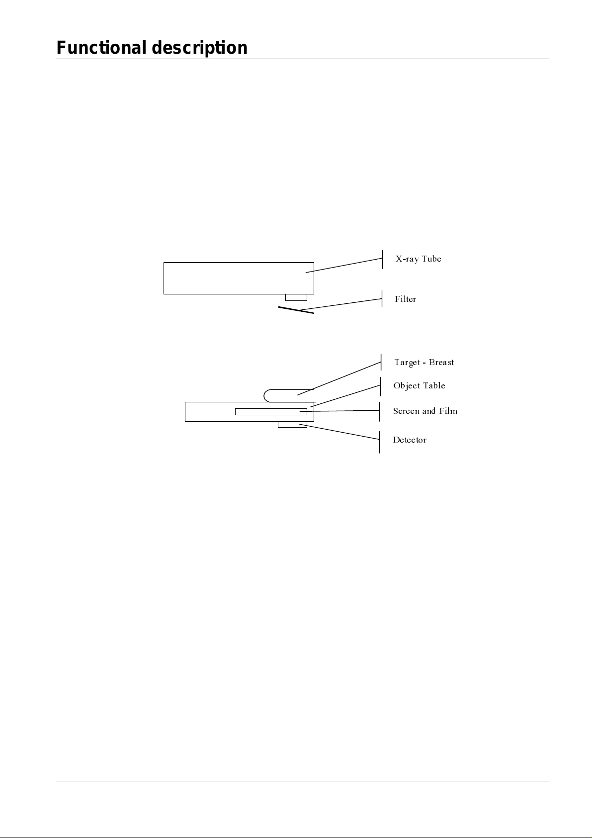
Picture below gives a schematic view of the exposure system.
X-ray Tube
ilter
1-1
Target - Breast
Obj ect Tab le
Screen and F ilm
Detector
Schematic view of the Mammomat
The generator supplies a voltage across the x-ray tube. The resulting radiation is filtered
before it reaches the target. Then it passes through an object table and reaches the fluorescent screen, which emits visible light giving the desired picture on the film. The part of
the radiation, which is not attenuated in the screen, reaches finally the detector and
results in a signal measured by the AEC unit. The main purpose of the AEC unit is to stop
the exposure so that the resulting picture is given the desired average optical density
based on current exposure settings and the measured signal from the detector.
Tube 1
When a voltage is applied acrossthe x-ray tube, the electrons, hitting the anode, initiate
radiation. The tube contains two different anode materials - molybdenum and tungsten giving different kind of x-ray spectra. There are actually two different anodes for each
mentioned material, used to give large and small focus for the x-ray beam. Small focus is
usedtogether with magnifying objecttables. Large focus is used for all other object tables.
Siemens AG Register 5 SPB7-230.898.01 Page 1 of 8 MAMMOMAT 1000/3000
Medical Engineering Rev. 01 04.00 TD SD 24
Page 6

1 - 2 Functional description
Theoperator isallowedto choosea desiredtubevoltagefrom a rangebetween23 and35
kV with 1 kV resolution. The voltage influences the energy spectrum and gives the operator a control of how hard x-rays are used during the exposure. The current through the
tube, which is directly proportional to the overall intensity of the beam, is a function of the
chosen voltage, the maximum power setting and the maximum current limit.
Neither the energy spectrum of the beam nor it's intensity are constantduring the exposure, due to raising and falling times for the voltage and the tube current. The voltage has
typical raising timesof app. 50 ms and the tube current 5 ms.
Filter 1
Different filtering is used to give the beam desired energy spectrum. For the molybdenum
anode, two filter selections are possible: molybdenum and rhodium. For the tungsten
anode, only rhodium is used as the filter material. This gives three possible anode/filter
combinations - Mo/Mo, Mo/Rh and W/Rh - resulting in three main kinds of x-ray beam.
Within each, a fine adjustment of the energy spectrum, i.e. the hardness of the beam, is
possible by adjusting the voltage.
Object Table 1
There are totally 7 different kinds of object tables that can be used described in the table
below.
Name Type Used beam focus Size Magnification
Grid 18 x 24 Grid Large 18 x 24 cm Grid 24 x 30 Grid Large 24 x 30 cm NoGrid 18 x 24 Grid-less Large 18 x 24 cm NoGrid 24 x 30 Grid-less Large 24 x 30 cm Mag 1.5 Magnification Small - 1.5
Mag 1.8 Magnification Small - 1.8
Biopsy
table
According to their x-ray characteristics and use, the object tables are ordered into four
groups: grid, grid-less, magnification and biopsy:
Gridtablesareusedtotakeordinarypicturesandareequippedwithamovinggridthat
reduces the amountof secondaryradiation, i.e.scatteredradiationfrom thetarget
object.
The grid-less tables are not equipped with a grid.
The Magnification tables have enlarged distance between the object and the film, giving
togetherwithsmallfocusof theradiation thedesiredmagnificationin thepicture.
Grid-less with
biopsyunit
Large
--
The biopsy table, also called stereotactictable, isvery similar to the grid-less tables.
Itis equippedwitha biopsyunit thattogether withstereotacticsisusedto identify the
3D-position of the biopsy target within the breast and perform the biopsy. The pictures
are smaller and can be taken from a direction not perpendicular tothe object table.
Angles of+
MAMMOMAT 1000/3000 Register 5 SPB7-230.898.01 Page 2 of 8 Siemens AG
10° are used.
Rev. 01 04.00 TD SD 24 Medical Engineering
Page 7

Functional description 1 - 3
Film and Screen 1
A considerable part of the radiation, which passes the target and possibly the grid of the
object table, is attenuated in the fluorescent screen. The energy is than emitted as visible
light and gives the desired picture on the film. The film is also sensitive to the x-rays, however the x-rays do not contribute to the picture significantly, compared to the visible light
emitted by the screen.
Detector 1
After passing the filter, the breast, the object table with screen and film, the radiation
finally reaches the detector. It is a semiconductor device that acts as a current source
supporting a current proportional to the overall intensity of the attenuated radiation. The
attenuation of the detector varies of course with the energy of the radiation, which makes
the generated current dependent on the energy spectrum of the beam. The generated
current is amplified and converted to a voltage level, which is the signal received from the
detector by the AEC unit.
Measured Signal 1
The signal from the detector is amplified on the AEC board and than converted to pulses
with a frequency proportional to the voltage level of the signal. The AEC unit contains a
PLD (Programmable Logic Device), programmed to register the detector signal by counting the pulses that the signal is conver ted to.
Gain 1
Before every exposure, there is a possibility to alter the gain applied to the detector signal
by the AEC board. Higher gain gives stronger signal to the V/F-converter, i.e. more pulses
and better precision in the counters of the PLD. There is however an upper bound for the
voltage level of the amplified signal - the V/F-converter functions for signals up to 10 V
and all voltages above this limit does not contribute to larger frequency of out-coming
pulses.
Dose Measuring 1
ThedoseismeasuredbycountingthepulsesfromtheV/F-converterduringatimeof
interest. This dose measure is not comparable to any conventional dose units because it
gives varying responses depending strongly on the energy spectrum of the radiation registered by the detector. However, for the same anode, filter, tube voltage, object table,
screen and object, this dose measure is directly proportional to the dose received by the
screen.
A logarithmic scale for the dose is also used. It is based on the usual definition of relative
exposure and the unit exposure points (EP).
Dose
ΕΦ
DoseDoseEP
01
log10 log log10
1
Dose
0
The used logarithmic scale is however absolute in the sense that 0 EP is defined to be
equal to 100 counts:
Dose
EP
10
Dose
counts
Siemens AG Register 5 SPB7-230.898.01 Page 3 of 8 MAMMOMAT 1000/3000
Medical Engineering Rev. 01 04.00 TD SD 24
10100
i.e.
Dose
EP
log10
Dose
100
counts
Page 8

1 - 4 Functional description
Dose Rate Measuring 1
In order to measure the dose rate, the pulses are counted during a period of time and the
resultingdoseisthendividedbythelengthofthetimeperiod.Theresultingdoserateis
an average over the chosen time interval.
Time Dependency 1
Due to the raising and falling times of the tube voltage and current, the detector signal is
also time dependent and has typical raising times of 50 ms.
Two Wings 1
The Mammomat can have one or two wings using separatedetectors.
User Choices 1
The following table summarises possible user choices affecting the exposure:
User choice Range Change consequence
Anode/ filter Mo/Mo, Mo/Rh, W/Rh Rough change of spectral properties of the
beam, possibly affecting power settings and
automatic choice of tube current.
Tube voltage 23 - 35 kV Fine change of spectral propertiesof the
beam, possibly affecting power settings and
automatic choice of tube current.
Speed H or D Choice between two sets of parameters for
two different film/ screen-combinations.
Density correction -24/8 to + 24/8 EP Relative adjustment of exposurelength,
0 = nominal AEC exposure.
Object table One of 7 See section Object Table
Wing 1 or 2 Different detectors in both wings.
Exposure control 1
Thecontrolmodelforthe AEC-unitis typically subdividedinto twoparts.Firstpart handles
the control of a single exposure with one set of exposure settings such as kV, anode/filter
etc. It is based on the knowledge of these parameters before the start and measurements
done during the exposure. Second part puts the control model for one exposure into a
systematic approach to all possible exposure settings for the Mammomat. It explains how
the entire set of control parameters for the AEC-unit is build up in order to cover all possible combinations of kV, object tables, anode/filter choices and up to 2 film/screen combinations.
MAMMOMAT 1000/3000 Register 5 SPB7-230.898.01 Page 4 of 8 Siemens AG
Rev. 01 04.00 TD SD 24 Medical Engineering
Page 9
Functional description 1 - 5
Ε
Φ
Control of One Exposure 1
Before start of exposure, the AEC-unit is only aware of exposure settings chosen by the
operator and has no knowledge of thickness or density of the actual breast. This implies a
two step approach to control of the entire exposure. First step is done before the exposure
start and contains calculation of an initial dose that will be executed before the AEC will
decide what to do next. During the execution of the initial dose, the unit measures the
dose rate and uses it to calculate a correction dose that has to be executed before the
exposure stops. When the AEC-unit has registered a total dose being equal to the sum of
the initial dose and the correction dose, it will stop the exposure.
Initial Dose 1
The initial d ose is chosen in EP. It co nsists of an estimated dose, a sensitivity, a sensitivity
correction and a density correction:
DcScSDoseDose
ΗΗΗΖ
EPEPEPEPestimatedEPinitial
,,,,,
where:
Dose
estimated,EP
- the estimated dose, a value specifically chosen for the used film/screen
combination, anode/filter combination, object table group and tube voltage.
- the sensitivity, a value controlling an overall level of target optical density for all
S,
EP
AEC-exposures.
SC,
- the sensitivity correction, chosen as a part of the calibration of specific equipment
EP
(Mammomat, object tables).
DC,
- the density correction, a value that is chosen by the operator for each exposure.
EP
The estimated dose is usually chosen, so it will give an OD = 1,5 for a 5 mm thick PMMAphantom.
Dose Correction 1
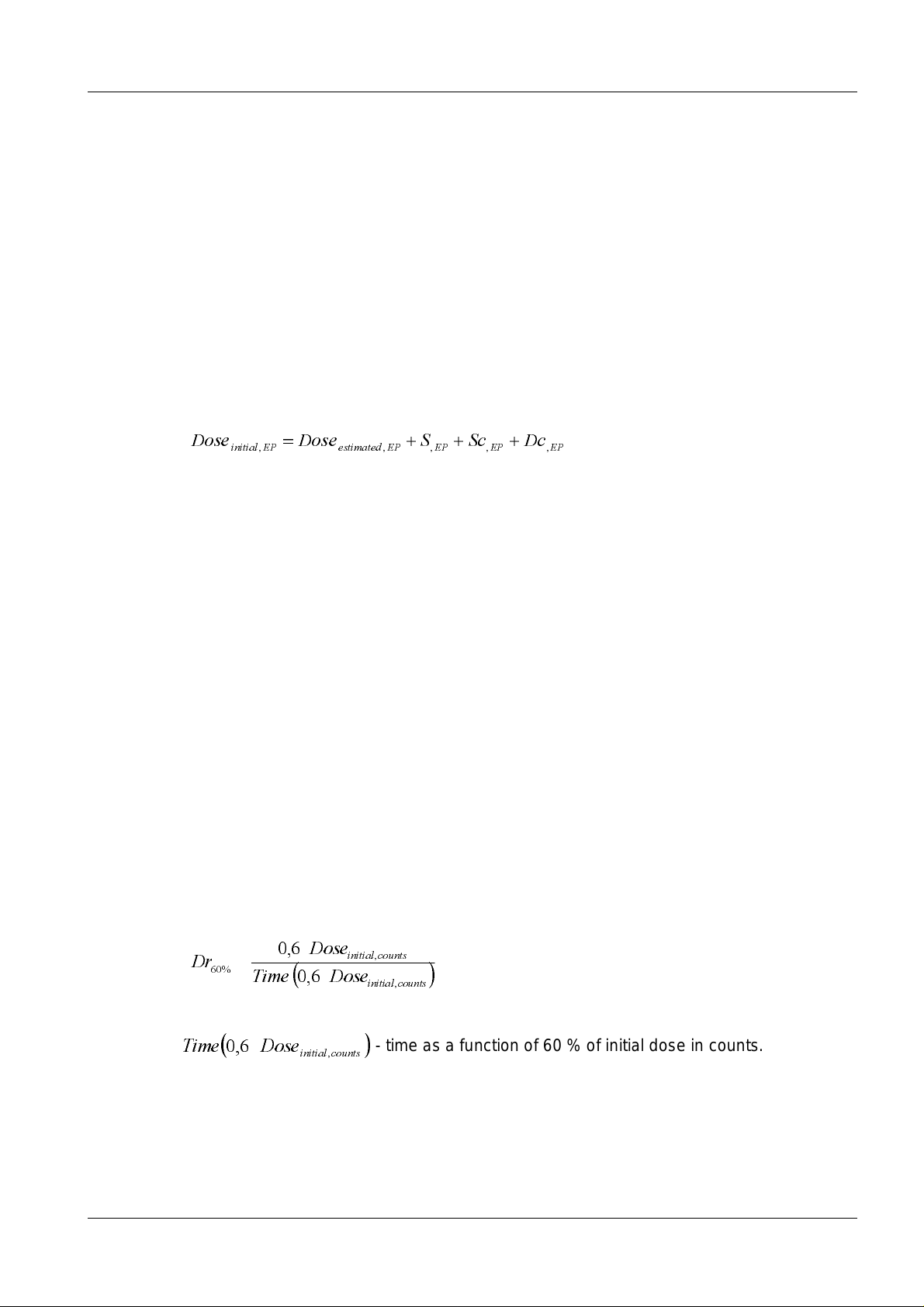
In order to measure the dose rate with the detector, the following procedure is used. The
initial dose is subdivided into a 60%-part and a 40%-part. Both parts are handled in the
AEC-unit by two separate counters, implemented in the PLD. At the exposure start, the
60% counter starts counting down at the rate of pulses from the V/F-converter that handles the amplifiedsignal from the detector. During counting down the 60% of the initial
dose, time is measuredby a time monitor. Whenthe 60% counterhas reached 0, the time
is read and used together with the actual value of 60 % of the initial dose as an average
dose rate:
Dose
Dr
6,0
%60
ΕΦ
DoseTime
6,0
countsinitial
,
countsinitial
,
where
DoseTime,6,0
Siemens AG Register 5 SPB7-230.898.01 Page 5 of 8 MAMMOMAT 1000/3000
Medical Engineering Rev. 01 04.00 TD SD 24
- time as a function of 60 % of initial dose in counts.
countsinitial
Page 10

1 - 6 Functional description
D
D
D
D
D
D
At the same time, the 40% counter is enabled and continues monitoring of the dose.
During execution of the remaining part of the initial dose, a calculation of the correction
dose has to be done. The measured dose rate is compared with a decreasing sequence
of dose rates, forming a so-called correction table. The index of each dose rate is a correctiondosein1/16EPneededforatargetgivingsuchadoserate,inordertogivethe
desired OD on the film. When the first dose rate, being equal to or lower than the measured, is found in the sequence, the corresponding index is used as the correction dose.
This givesthe total dose of:
ΕΦ
ΗΖ
In order to receive the dose correction in counts, which is needed for initialising the third
and last dose counter in the PLD of the AEC unit, the following formula is used:
DoseDoseDose
ϑΖ
where the total dose and the initial dose are translatedfrom EP to counts.
When the 40 % counter reaches 0, the correction counter initialised with the correction
dose is enabled. When the correction dose is executed as well, the AEC-unit stops the
exposure. The entire picture of dose calculation and execution is given in the figure below.
DoseDcScSDose
ΖΗΗΗ
EPinitialEPEPEPEPestimated
,,,,,
DrDoseDoseDose
EPcorrEPinitialEPtotal
countsinitialcountstotalcountscorr
,,,
%60,,,
Exposure start
Counter 60% = 0
Read time and
calculate correction
Dose
,
EP
Dose
Dose
Check correction table to get
Ζ
,
counts
countsinitial
,
Dose
6,0
DoseTime
ΕΦ
6,0
ΕΦ
DrDose
EPcorr
10
10100
,
countsinitial
Counter 40%
Counter 60%
Counter Corr
,
countsinitial
Ζ
4,0
6,0
%60,
Dr
Counter 40% = 0
correction loaded
Counter Corr = 0
Exposure finnished
%60
ose
Dose
counts
ose
10100
Dose
,
EP
10
ose
ϑΖ
countinitialcountstotalcountscorr
,,,
ose
ose
ose
ΗΖ
EPcorrEPinitialEPtotal
,,,
Dose calculation and execution in the AEC-unit
MAMMOMAT 1000/3000 Register 5 SPB7-230.898.01 Page 6 of 8 Siemens AG
Rev. 01 04.00 TD SD 24 Medical Engineering
Page 11

Functional description 1 - 7
Entire Set of Control Parameters 1
The entire set of control parameters consists of three differently used parts. First part contains parameters that are chosen specifically for a film/screen-combination at laboratory
by series of tests. These are called correction tables. Second part is sensitivity correction,
used to calibrate a specific Mammomat. Third part is sensitivity, used to adjust the target
OD for a specific Mammomat and one film/screen-combination (i.e. one speed) to the
level requested by the customer.
Correction Tables 1
Correction tables contains gain values, estimated doses and correction values. These are
structured in the following way:
Gain
(one value)
Set for 23 kV
Set for grid tables
Set fo r Mo/Mo
Set for one film/screen
Estimated dose
(one value)
4 sets
Correction sequence of dose rates
(a minimum of 80 values)
…
13 sets
…
Set fo r Mo/Rh Set for W/Rh
Set for stereo table
Set for 35 kVSet for 24 kV
kV-set: one gain value, one estimated dose and a minimumof 80 dose rates forming the
correction sequence, define the set of parameters used for specific tube voltage, object
table group, anode/filter and speed.
Table-group-set: 13 kV-sets defining the set of parameters for all tube voltages, one
object table group, anode/filter and speed.
Anode/Filter-set: 4 table-group-sets defining the set of parameters for all voltages, all
object table groups, one anode/filter and speed.
Film/screen-set: 3Anode/Filter-sets defining the set of parametersfor all user choices
withinone speedi.e.one film/screen-combination.
Because the Mammomat gives the user a possibility to choose between two different
speeds, it can be equipped withtwo film/screen sets of parameters - one for each speed,
HandD.
Siemens AG Register 5 SPB7-230.898.01 Page 7 of 8 MAMMOMAT 1000/3000
Medical Engineering Rev. 01 04.00 TD SD 24
Page 12

1 - 8 Functional description
Sensitivity Correction 1
The sensitivity correction is possible to choose differently for all 7 object tables, 3 anode/
filter- combinations and 2 speeds. This makes totally 42 possible values, adjustable in
1/8 EP-steps.
Sensitivity 1
One sensitivity setting is allowed for each speed, H and D, wh ich gives totally 2 sensitivities, adjustable in 1/8 EP-steps.
MAMMOMAT 1000/3000 Register 5 SPB7-230.898.01 Page 8 of 8 Siemens AG
Rev. 01 04.00 TD SD 24 Medical Engineering
Page 13

Error messages 2
ERROR messages of the new AEC Er 4xx are described in the document
"service program" from SW 4.0.
2-1
NOTICE
NOTICE
The error messages Er 419 - Er 422 are internal errors.
They do not interfer with an exposure and are not shown on the
control panel.
Please report this errors immediately in accordance with the
established processes.
Siemens AG Register 5 SPB7-230.898.01 Page 1 of 2 MAMMOMAT 1000/3000
Medical Engineering Rev. 01 04.00 TD SD 24
Page 14

2 - 2 Error messages
This page intentionally left blank.
MAMMOMAT 1000/3000 Register 5 SPB7-230.898.01 Page 2 of 2 Siemens AG
Rev. 01 04.00 TD SD 24 Medical Engineering
Page 15

Parts replacement 3
Action list for MAMMOMA T 1000/ 3000 with new AEC 3
Change of Consequence
3-1
Power
Filter
Tube
Inverter
Detector
D701
AE C T est according to
"Installation and startup
instructions for MAMMOMAT
1000/3000"
Install o ld backup of A EC and
correction tables
En tire calibration
of AEC
AEC Test
Not
ok
Detector
n o r ma lization
D702
D705
Object table
Adjust kV Filamen t adaption
S ens it iv it y corr ection
adjustm ent
Siemens AG Register 5 SPB7-230.898.01 Page 1 of 2 MAMMOMAT 1000/3000
Medical Engineering Rev. 01 04.00 TD SD 24
Page 16

3 - 2 Parts replacement
This page intentionally left blank.
MAMMOMAT 1000/3000 Register 5 SPB7-230.898.01 Page 2 of 2 Siemens AG
Rev. 01 04.00 TD SD 24 Medical Engineering
Page 17

Description of LED’s and measuring points 4
Measuring points on AEC board D701 4
TX Communication from D701
RX Bus communication
KVA_EXP_DONE Indicates end of normal exposure
KVA_ABORT_EXP Indicates exposure aborted by CPU on D701
0VD 0VA VCC 5 V
D15V 15 V for logic
P15V + 15 V
N15V -15 V
VOSCTL 1 Signal for control of offset compensation
SEL_RDL Detector signal
4-1
A3_RDL Amplified detector signal
A4_RDL Amplified detector signal compensated for offset
AD_RDL V/F converter output signal
FRDL V/F converter output pulses
OFS_RDL Offset compensation signal
X1 For factory test only
X2 For factory test only
Switches on AEC board D701 4
S1 For factory test only, set to zero
Jumpers on AEC board D701 4
X114 1-2Normal/2-3Nodosemonitoring
J1 Forces offset compensation mode
J2 Forces measuring mode
J3 Generates an offset test signal
Siemens AG Register 5 SPB7-230.898.01 Page 1 of 4 MAMMOMAT 1000/3000
Medical Engineering Rev. 01 04.00 TD SD 24
Page 18

4 - 2 Description of LED’s and measuring points
LEDs on AEC board D701 4
Processor
(status)
Gain PLD
(detected
error)
PLD
(configuration
status)
Processor LEDs ()
x x x x
x x x
x x
( EPROM Check finished)
x
x x
x x
x x
CPU not Running
RAM Check
EPROM Check
Flash check
Ready
RAM Error EPROM Error
Gain LEDs ()
0
2
=1
1
2
2
2
3
2
4
2
5
2
6
2
7
2
=2
=4
=8
=16
=32
=64
=128
NOTICE
x
x
x x
x
x x
x x
x x x
The gain displayed corresponses to the total gain, which is a
function of the correction table gain (SW controlled) and the D7 01
gain (HW controlled).
MAMMOMAT 1000/3000 Register 5 SPB7-230.898.01 Page 2 of 4 Siemens AG
Rev. 01 04.00 TD SD 24 Medical Engineering
Page 19

Description of LED’s and measuring points 4 - 3
PLD LED ()
If PLD is correctly configured and running, the LED is toggled with period of 1 sec.
PLD LEDs ()
If an error is detectedby the PLD an 8-bit code is displayed on the4 LED’s in a sequence
as follows:
1. Initially the 4 LSB (least significantbits) of the error code are displayed during
1second.
2. Thenthe 4 MSB(mostsignificantbits)of theerrorcode aredisplayed during
1second.
To indicate that the entire error code has been displayed, each of the four LED’sare
turnedon one at time.
The sequence described above will be repeated until reset of the PLD.
An error code detected by the PLD can also be found with the Service PC program by
entering the menu <Normal mode> <AEC data>.
Siemens AG Register 5 SPB7-230.898.01 Page 3 of 4 MAMMOMAT 1000/3000
Medical Engineering Rev. 01 04.00 TD SD 24
Page 20

4 - 4 Description of LED’s and measuring points
This page intentionally left blank.
MAMMOMAT 1000/3000 Register 5 SPB7-230.898.01 Page 4 of 4 Siemens AG
Rev. 01 04.00 TD SD 24 Medical Engineering
Page 21

Tests 5
Check the AEC according to "Installation and start-up instructions" for MAMMOMAT 1000/ 3000 5
If AEC tests fails, check that:
correct plexi has been used and positioning of plexi is correct and that used kV-setting is
correct.
usedfilm/screencombination iscorrect(reference cassetteshallbe used).
correction for variations in film developing process has been correctly performed.
5-1
Siemens AG Register 5 SPB7-230.898.01 Page 1 of 2 MAMMOMAT 1000/3000
Medical Engineering Rev. 01 04.00 TD SD 24
Page 22

5-2 Tests
This page intentionally left blank.
MAMMOMAT 1000/3000 Register 5 SPB7-230.898.01 Page 2 of 2 Siemens AG
Rev. 01 04.00 TD SD 24 Medical Engineering
Page 23

Problems during Installation/ Service 6
AEC Correction tables 6
Measured d ose rate exceeds + 30% 6
Perform
calibr a t ion of
AE C correction
table s
Me asured dose
rate exceeds +
30%
6-1
Not
OK
Not
OK
Not
OK
Ch eck size and
positioning of
used plexi
OK
Check that correct
film/s c r een is used
OK
C heck supply
voltage to the unit
Accept, but note
the e xposure s
where the
measured dose
rate exceeds!
Siemens AG Register 5 SPB7-230.898.01 Page 1 of 8 MAMMOMAT 1000/3000
Medical Engineering Rev. 01 04.00 TD SD 24
Page 24

6 - 2 Problems during Installation/ Service
Error during backup from disc/ floppy 6
Perform Backup
from
se rvic e p rog ra m
E rror d urin g
Backup
Rep eat
3times
Not
OK
Not
OK
Not
OK
Check backup files
on disc/ floppy
OK
Che ck co nnection
with Service PC
OK
Perform backup
Not OK a fter 3 times
Fata l e rro r
MAMMOMAT 1000/3000 Register 5 SPB7-230.898.01 Page 2 of 8 Siemens AG
Rev. 01 04.00 TD SD 24 Medical Engineering
Page 25

Problems during Installation/ Service 6 - 3
Error during reset of installation parameters 6
Perform R eset
inst a l la t io n
pa ra m e te rs fro m
se rvic e p rog ra m
E rro r o c cu re d
Not
OK
Re peat
3times
Not
OK
Che ck co nnection
with Service PC
OK
Perform reset
Not OK a fter 3 times
Chan ge D7 01
Siemens AG Register 5 SPB7-230.898.01 Page 3 of 8 MAMMOMAT 1000/3000
Medical Engineering Rev. 01 04.00 TD SD 24
Page 26

6 - 4 Problems during Installation/ Service
Errors during offset compensation test 6
Perform Offset
co mpe n s a tion te s t w ith
service program
Measured dose
rate out of range
No
Detector blocked
from radiation
Yes
Disconnect detector
cables X10 & X11
Press F3
Measured dose
rateoutofrange?
Yes
Change D701
Connect X 10 & X 11
Press F3
No
Measured dose
rate out of range ?
Yes
fro m 6-5 to 6-5
MAMMOMAT 1000/3000 Register 5 SPB7-230.898.01 Page 4 of 8 Siemens AG
Rev. 01 04.00 TD SD 24 Medical Engineering
F at al erro r
No
OK
Page 27

Problems during Installation/ Service 6 - 5
from 6-4to 6-4
Connect X 10
Press F3
No
Connect X 11
Press F3
Measured dose
rate out of range ?
Change detector
wing 2
Outofrange?
Yes
Change detector
wing 1
Siemens AG Register 5 SPB7-230.898.01 Page 5 of 8 MAMMOMAT 1000/3000
Medical Engineering Rev. 01 04.00 TD SD 24
Page 28

6 - 6 Problems during Installation/ Service
Detector Normalization 6
Normalization factor out of range 6
Perform
exposures for
nor ma liza t ion with
service program
N or ma liza t io n
factor out of range
after pressing
<F2> ?
Not
OK
Not
OK
Not
OK
Check size and
position of u se d P lex i
OK
Check that correct
table is use d and no
cassette is inserted
OK
Check connection of
detector
OK
Change detector
Fa ta l e rro r
MAMMOMAT 1000/3000 Register 5 SPB7-230.898.01 Page 6 of 8 Siemens AG
Rev. 01 04.00 TD SD 24 Medical Engineering
Page 29

Problems during Installation/ Service 6 - 7
Miscellaneous 6
Communication Errors with Service PC 6
Check if the PC is equipped with an IRtransmitter and disable it.
Siemens AG Register 5 SPB7-230.898.01 Page 7 of 8 MAMMOMAT 1000/3000
Medical Engineering Rev. 01 04.00 TD SD 24
Page 30

6 - 8 Problems during Installation/ Service
This page intentionally left blank.
MAMMOMAT 1000/3000 Register 5 SPB7-230.898.01 Page 8 of 8 Siemens AG
Rev. 01 04.00 TD SD 24 Medical Engineering
 Loading...