

Page 1

MAMMOMAT 1000/3000
Installation
Installation and Start-Up Instructions
© Siemens AB 1999
The reproduction, transmission or
use of this document or its contents
is not permitted without express
written authority. Offenders will be
liable for damages. All rights,
including rights created by patent
grant or registration of a utility
model _or_ design,_are_ reserved.
Register 3 English
Print No.: SPB7-230.033.07.03.02 Doc . Gen. Date: 11.99
Replaces: SPB7-230.033.07.02.02
65 27 464
Page 2

0 - 2 Revision
Chapter Page Revision
17 All 03
Mammomat 1000/3000 Register 3 SPB7-230.033.07 Page 2 of 2 Siemens-Elema AB
Installation and Start-Up Rev. 03 11.99 SPS-UD Solna, Sweden
Page 3

Contents 0 - 1
Page
1 _______Prerequisites __________________________________________________1 - 1
General . . . . . . . . . . . . . . . . . . . . . . . . . . . . . . . . . . . . . . . . .1 - 1
MAMMOMAT 1000 . . . . . . . . . . . . . . . . . . . . . . . . . . . . . . . . . 1 - 1
MAMMOMAT 3000 . . . . . . . . . . . . . . . . . . . . . . . . . . . . . . . . . 1 - 2
Meters and appliances, tools . . . . . . . . . . . . . . . . . . . . . . . . . . . . . . 1 - 3
Meters and appliances required. . . . . . . . . . . . . . . . . . . . . . . . . . .1 - 3
Tools required . . . . . . . . . . . . . . . . . . . . . . . . . . . . . . . . . . . . 1 - 3
Important notes on start-up . . . . . . . . . . . . . . . . . . . . . . . . . . . . . . . 1 - 4
Checking and recording for the area of applicati on of the X-ray decree (§16 Germany)1 - 4
Checking and recording for the DHHS area of applicati on . . . . . . . . . . . . . . . 1 - 5
Sections . . . . . . . . . . . . . . . . . . . . . . . . . . . . . . . . . . . . . . . 1 - 5
Note on delivery state . . . . . . . . . . . . . . . . . . . . . . . . . . . . . . . . . . 1 - 5
2 _______Protective measures ____________________________________________ 2 -1
Protective measures. . . . . . . . . . . . . . . . . . . . . . . . . . . . . . . . . . . 2 -1
3 _______Preparatory work_______________________________________________3 - 1
General . . . . . . . . . . . . . . . . . . . . . . . . . . . . . . . . . . . . . . . . .3 - 1
Scope of delivery . . . . . . . . . . . . . . . . . . . . . . . . . . . . . . . . . . 3 - 1
Unpacking . . . . . . . . . . . . . . . . . . . . . . . . . . . . . . . . . . . . . . 3 - 1
Unpacking the stand. . . . . . . . . . . . . . . . . . . . . . . . . . . . . . . . . . . 3 - 2
Removing the transport safeguards. . . . . . . . . . . . . . . . . . . . . . . . . . . 3 - 3
Removing the swivel-arm system transport sa feguard . . . . . . . . . . . . . . . 3 - 3
Transport safeguard for the lifting carriage . . . . . . . . . . . . . . . . . . . . . 3 - 3
Transport safeguard for the rotary motion. . . . . . . . . . . . . . . . . . . . . . . . 3 - 4
Protective strips for the metal curtain . . . . . . . . . . . . . . . . . . . . . . . . . . 3 - 5
Unpacking the generator and mounting the radiation shield (optional) . . . . . . . . .3 - 6
4 _______Installing the generator and the stand _____________________________4 - 1
Arranging the components . . . . . . . . . . . . . . . . . . . . . . . . . . . . . . . 4 - 1
Notes on installations with separate generat or and separate control console. . . . 4 - 1
Free-standing radiation shield (option) . . . . . . . . . . . . . . . . . . . . . . . . . 4 - 2
Removing the generator cover . . . . . . . . . . . . . . . . . . . . . . . . . . . . .4 - 2
Installing the cable ducts . . . . . . . . . . . . . . . . . . . . . . . . . . . . . . . . 4 - 3
Installations with separate control console . . . . . . . . . . . . . . . . . . . . . 4 - 3
Laying the cable harness . . . . . . . . . . . . . . . . . . . . . . . . . . . . . . . . 4 - 4
Installations with separate control console . . . . . . . . . . . . . . . . . . . . . 4 - 5
Aligning the stand . . . . . . . . . . . . . . . . . . . . . . . . . . . . . . . . . . . . 4 - 6
5 _______Cable connections______________________________________________5 - 1
EMC measures . . . . . . . . . . . . . . . . . . . . . . . . . . . . . . . . . . . . . 5 - 1
EMC measures at the cable entry. . . . . . . . . . . . . . . . . . . . . . . . . . . .5 - 1
Siemens-Elema AB Register 03 SPB7-230.033.07 Page 1 of 4 MAMMOMAT 1000/3000
Solna, Sweden Rev. 03 11.99 SPS-UD Installation and Start-up
Page 4

0 - 2 Contents
Page
Fitting the hose clamps and ferrite sleeves
. . . . . . . . . . . . . . . . . . . . . . . . . . . . . . . . . . . . . . . . . . . 5 - 1
Note on separate control console and separate generator. . . . . . . . . . . . . 5 - 2
EMC measures on the bottom plate . . . . . . . . . . . . . . . . . . . . . . . . . . 5 - 3
Fitting the cables X1, X8 and X9 onto the bottom plate . . . . . . . . . . . . . . 5 - 3
Connecting the stand cable-ha rness . . . . . . . . . . . . . . . . . . . . . . . . . . 5 - 4
High-voltage connectors, alternative types . . . . . . . . . . . . . . . . . . . . . 5 - 4
Connecting the high-voltage connector . . . . . . . . . . . . . . . . . . . . . . . . 5 - 5
Connecting the cable harness to the generat or . . . . . . . . . . . . . . . . . . . . 5 - 6
Unit control cable X1 . . . . . . . . . . . . . . . . . . . . . . . . . . . . . . . . 5 - 6
Filament cable X8. . . . . . . . . . . . . . . . . . . . . . . . . . . . . . . . . . 5 - 6
Power supply cable X14 . . . . . . . . . . . . . . . . . . . . . . . . . . . . . . 5 - 6
IONTOMAT signal cable X10 and X11 . . . . . . . . . . . . . . . . . . . . . . . 5 - 6
Rotating anode cable X9 . . . . . . . . . . . . . . . . . . . . . . . . . . . . . . 5 - 7
Installations with separate control console and separate generator
. . . . . . . . . . . . . . . . . . . . . . . . . . . . . . . . . . . . . . . . . . . 5 - 8
Main voltage connection . . . . . . . . . . . . . . . . . . . . . . . . . . . . . . . .5 - 10
Connecting the incoming mains to the stand (400 V, 2-pha se). . . . . . . . . . . . .5 - 11
400 V 2-phase connection . . . . . . . . . . . . . . . . . . . . . . . . . . . . .5 - 11
Connecting the mains supply to the generator (400 V, 2-phase). . . . . . . . . . . .5 - 12
Measures for changing from 2-phase to 1-phase con nection . . . . . . . . . . .5 - 13
6 ______ Mains connection and power supply_______________________________6 - 1
Checks before powering up the generator . . . . . . . . . . . . . . . . . . . . . . . 6 - 1
Measuring the line resistance . . . . . . . . . . . . . . . . . . . . . . . . . . . . . 6 - 1
Checking the line voltage in the generator . . . . . . . . . . . . . . . . . . . . . . . 6 - 2
Checking the supply voltages . . . . . . . . . . . . . . . . . . . . . . . . . . . . . 6 - 3
7 ______ Attaching the swivel-arm covers __________________________________7 - 1
Attaching the swivel-arm covers . . . . . . . . . . . . . . . . . . . . . . . . . . . . 7 - 1
Arranging the swivel-arm system. . . . . . . . . . . . . . . . . . . . . . . . . . 7 - 1
Connecting the cables to control-button boards and patient handles . . . . . . . 7 - 1
Attaching the side covers . . . . . . . . . . . . . . . . . . . . . . . . . . . . . . 7 - 2
Attaching the front cover . . . . . . . . . . . . . . . . . . . . . . . . . . . . . . 7 - 2
8 ______ Checking the microprocessors ___________________________________8 - 1
Microprocessors . . . . . . . . . . . . . . . . . . . . . . . . . . . . . . . . . . . . 8 - 1
9 ______ Checks without high voltage _____________________________________9 - 1
Checks without high voltage . . . . . . . . . . . . . . . . . . . . . . . . . . . . . . 9 - 1
10 _____ Checks with high voltage _______________________________________10 - 1
Preparation . . . . . . . . . . . . . . . . . . . . . . . . . . . . . . . . . . . . . . .10 - 1
Checking X-ray tube high voltage, tube currrent and mAs values . . . . . . . . . . .10 - 2
MAMMOMAT 1000/3000 Register 03 SPB7-230.033.07 Page 2 of 4 Siemens-Elema AB
Installation and Start-up Rev. 03 11.99 SPS-UD Solna, Sweden
Page 5

Contents 0 - 3
Page
Tube current reduction. . . . . . . . . . . . . . . . . . . . . . . . . . . . . . . 10 - 2
Oscilloscope diagrams. . . . . . . . . . . . . . . . . . . . . . . . . . . . . . . 10 - 3
11 ______Start-up and functional test of the IONTOMAT______________________11 - 1
Checking and programming with the service PC . . . . . . . . . . . . . . . . . . . 11 - 1
Sensitivity . . . . . . . . . . . . . . . . . . . . . . . . . . . . . . . . . . . . . 11 - 1
Sensitivity correction. . . . . . . . . . . . . . . . . . . . . . . . . . . . . . . . 11 - 2
Correction curve . . . . . . . . . . . . . . . . . . . . . . . . . . . . . . . . . . 11 - 2
Other film/screen combinations . . . . . . . . . . . . . . . . . . . . . . . . . . 11 - 3
Correction curve diagrams. . . . . . . . . . . . . . . . . . . . . . . . . . . . . 11 - 4
Checking the film density . . . . . . . . . . . . . . . . . . . . . . . . . . . . . . . 11 - 8
Checking the automatic transparency adaption. . . . . . . . . . . . . . . . . . . . 11 - 9
Checking the automatic transparency adaption and OPDOSE (MAMMOMAT 3000 only) 11
- 10
Checking cut-off dose and re solution (§16 Germany). . . . . . . . . . . . . . . . .11 - 11
Output values of constancy testing (§16 Ge rmany). . . . . . . . . . . . . . . . . .11 - 12
12 ______Further programming __________________________________________12 - 1
Setting the real time clock . . . . . . . . . . . . . . . . . . . . . . . . . . . . . . . 12 - 1
Prerequisite . . . . . . . . . . . . . . . . . . . . . . . . . . . . . . . . . . . . 12 - 1
Setting the time in the Mammomat . . . . . . . . . . . . . . . . . . . . . . . . . . 12 - 1
Setting the tube-current reduction. . . . . . . . . . . . . . . . . . . . . . . . . . . 12 - 1
Reducing the generator power . . . . . . . . . . . . . . . . . . . . . . . . . . . . 12 - 2
Main menu: . . . . . . . . . . . . . . . . . . . . . . . . . . . . . . . . . . . . 12 - 2
13 ______Checking the swivel-arm system_________________________________13 - 1
Rotary motion . . . . . . . . . . . . . . . . . . . . . . . . . . . . . . . . . . . . . 13 - 1
Vertical adjustment . . . . . . . . . . . . . . . . . . . . . . . . . . . . . . . . . . 13 - 2
Emergency stop . . . . . . . . . . . . . . . . . . . . . . . . . . . . . . . . . . . . 13 - 3
14 ______Field light ____________________________________________________14 - 1
Checking and adjusting the field light time . . . . . . . . . . . . . . . . . . . . . . 14 - 1
Checking the field light time . . . . . . . . . . . . . . . . . . . . . . . . . . . . 14 - 1
Adjusting the field light time . . . . . . . . . . . . . . . . . . . . . . . . . . . . . . 14 - 2
15 ______Checking the compression device and OPCOMP ___________________15 - 1
Checking the compression device. . . . . . . . . . . . . . . . . . . . . . . . . . . 15 - 1
Decompression button (only with separate control console) . . . . . . . . . . . 15 - 2
Checking the OPCOMP . . . . . . . . . . . . . . . . . . . . . . . . . . . . . . . . 15 - 3
Adapting OPCOMP . . . . . . . . . . . . . . . . . . . . . . . . . . . . . . . . . . 15 - 3
16 ______Checking the exposure blocking_________________________________16 - 1
Checking the exposure blocking . . . . . . . . . . . . . . . . . . . . . . . . . . . 16 - 1
Siemens-Elema AB Register 03 SPB7-230.033.07 Page 3 of 4 MAMMOMAT 1000/3000
Solna, Sweden Rev. 03 11.99 SPS-UD Installation and Start-up
Page 6

0 - 4 Contents
Page
17 _____ Checking the radiation field limitation_____________________________17 - 1
General. . . . . . . . . . . . . . . . . . . . . . . . . . . . . . . . . . . . . . . . .17 - 1
Measuring procedure. . . . . . . . . . . . . . . . . . . . . . . . . . . . . . . . . .17 - 2
Evaluation . . . . . . . . . . . . . . . . . . . . . . . . . . . . . . . . . . . . . . .17 - 3
Alignment radiation field/light field . . . . . . . . . . . . . . . . . . . . . . . . .17 - 3
Radiation field limitation . . . . . . . . . . . . . . . . . . . . . . . . . . . . . .17 - 3
18 _____ Final procedures _____________ __ ___ __ __________________________18 - 1
Service PC and measuring instruments . . . . . . . . . . . . . . . . . . . . . . . .18 - 1
Recording the programmed values . . . . . . . . . . . . . . . . . . . . . . . . .18 - 1
Reading the exposure counter and deleting the error memory. . . . . . . . . . .18 - 1
Saving the configuration file . . . . . . . . . . . . . . . . . . . . . . . . . . . .18 - 1
Removing the measuring instruments . . . . . . . . . . . . . . . . . . . . . . . . .18 - 2
Checking the protective grounding res istance . . . . . . . . . . . . . . . . . . . . .18 - 2
Mounting the cable duct covers . . . . . . . . . . . . . . . . . . . . . . . . . . . .18 - 2
Mounting the stand covers . . . . . . . . . . . . . . . . . . . . . . . . . . . . . . .18 - 2
Mammomat stand with separate rear side covers. . . . . . . . . . . . . . . . . .18 - 3
Mammomat stand with single rear cover.. . . . . . . . . . . . . . . . . . . . . .18 - 4
Fitting the Mammomat cap . . . . . . . . . . . . . . . . . . . . . . . . . . . . .18 - 5
Fitting the cable outlet cover . . . . . . . . . . . . . . . . . . . . . . . . . . . .18 - 5
Mounting the front cover onto the generator . . . . . . . . . . . . . . . . . . . . . .18 - 6
Final protective grounding resistance test . . . . . . . . . . . . . . . . . . . . . . .18 - 6
Face shield . . . . . . . . . . . . . . . . . . . . . . . . . . . . . . . . . . . . . . .18 - 7
Warni ng label on control panel . . . . . . . . . . . . . . . . . . . . . . . . . . . . .18 - 8
Affixing the ide n tification labels. . . . . . . . . . . . . . . . . . . . . . . . . . . . .18 - 9
Returning the LINA card . . . . . . . . . . . . . . . . . . . . . . . . . . . . . . . .18 - 9
19 _____ Bolting the stand/generator to the floor ___________________________19 - 1
Stativ and generator with integrated radiation shield and control panel . . . . . . . .19 - 1
Installation with separate generator . . . . . . . . . . . . . . . . . . . . . . . .19 - 2
Free-standing radiation shield (option) . . . . . . . . . . . . . . . . . . . . . . .19 - 3
20 _____ Appendix ______________ ___ ________________________________ ___20 - 1
Working with the service PC . . . . . . . . . . . . . . . . . . . . . . . . . . . . . .20 - 1
Description of the syntax used in these instructions . . . . . . . . . . . . . . . .20 - 1
Connecting the service PC . . . . . . . . . . . . . . . . . . . . . . . . . . . . .20 - 2
Starting up and using the service PC. . . . . . . . . . . . . . . . . . . . . . . .20 - 2
Measuring protocol . . . . . . . . . . . . . . . . . . . . . . . . . . . . . . . . . . .20 - 3
MAMMOMAT 1000/3000 Register 03 SPB7-230.033.07 Page 4 of 4 Siemens-Elema AB
Installation and Start-up Rev. 03 11.99 SPS-UD Solna, Sweden
Page 7
Prerequisites 1
General 1
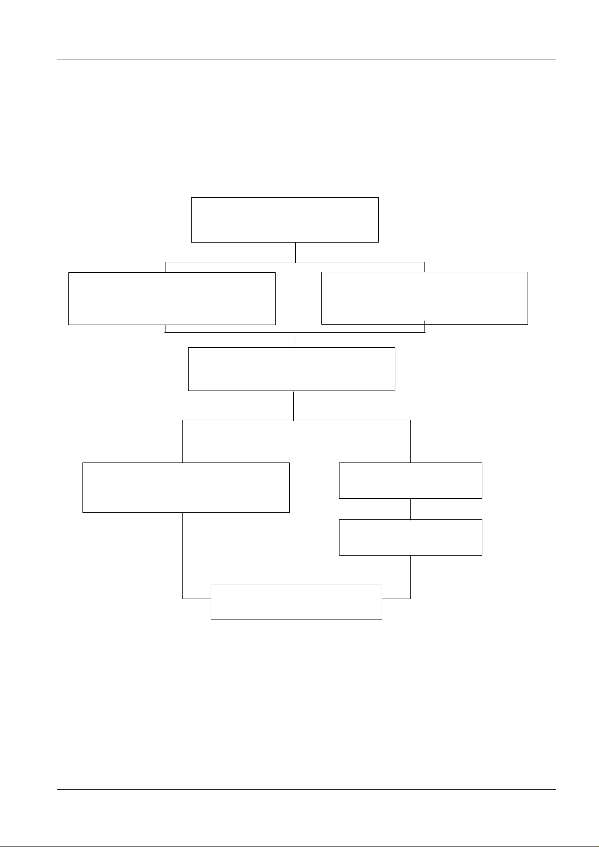
The configuration of the Mammomat installation is dependent on the customer’s choice.
Up to twelve various combinations are possible as shown below:
MAMMOMAT 1000 1
Mammomat 1000 - Basic unit
1 - 1
Molybdenum anode X-ray tube
assembly with filter Mo 0.03
Fixed object-table arm
("Wing 2" no counterweight)
Generator with integrated
control panel and radiation shield
Molybdenum anode X-ray tube
assembly with filter disc
Mo 0.03/Rh 0.025
Separate generator
Separate control console
Free-standing radiation shield
Fig. 1
Siemens-Elema AB Register 3 SP B7-230.033.07 Page 1 of 6 Mammomat 1000/3000
Solna, Sweden Rev. 03 11.99 SPS-UD Installation and Start-Up
Page 8
1 - 2 Prerequisites
NOTICE
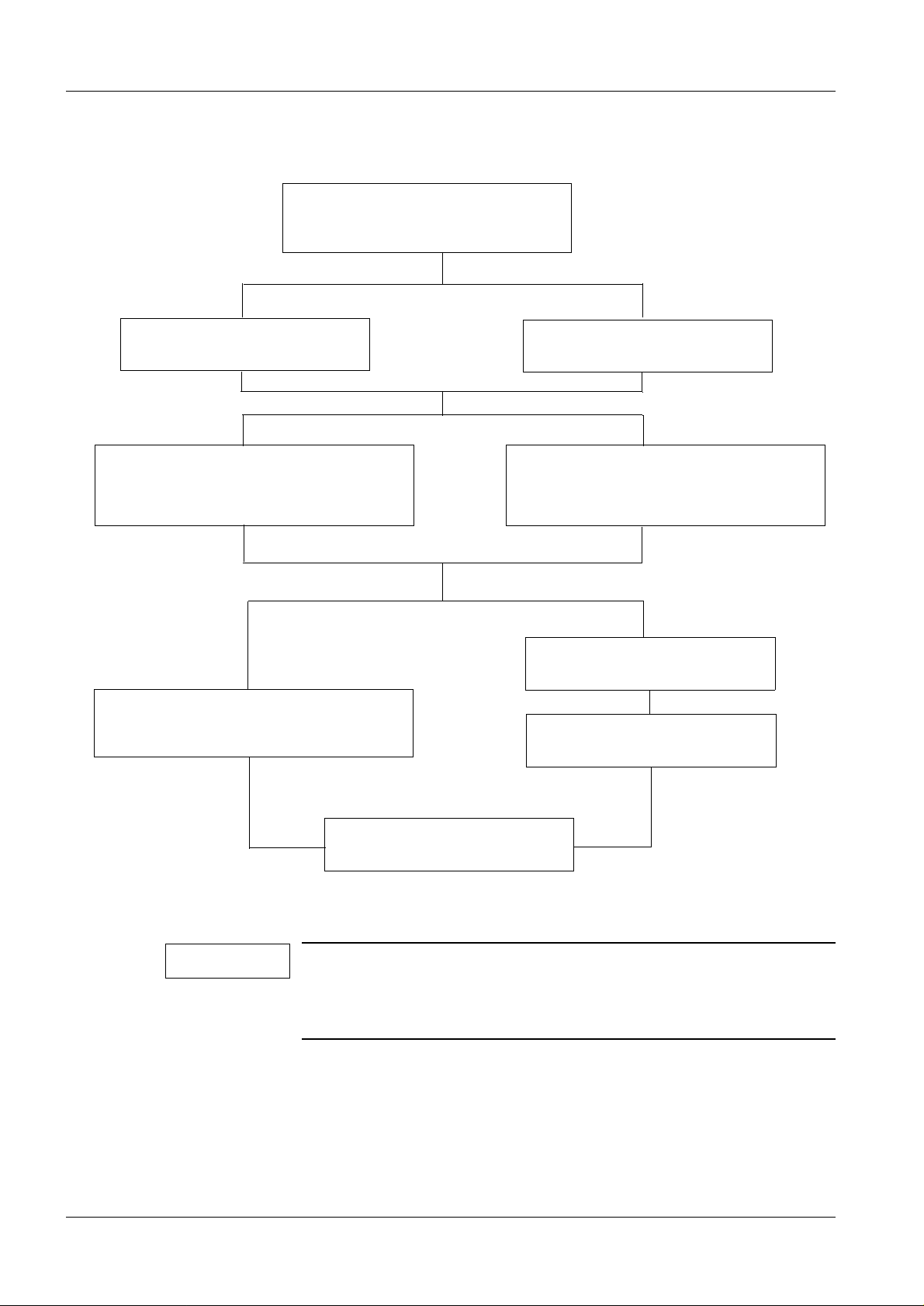
MAMMOMAT 3000 1
Mammomat 3000 - Basic unit
Pivoting object-table arm
("Wing 1"+ "Wing 2")
Molybdenum/tungsten anode X-ray
tube assembly with filter disc
Mo 0.03/Rh 0.025/Rh 0.050
Generator with integrated
control panel and radiation shield
Fixed object-table arm
("Wing 1" + counterweight)
Molybdenum anode X-ray tube
assembly with filter disc
Mo 0.03/Rh 0.025
Separate generator
Separate control console
Free-standing radiation shield
Fig. 2
A P40 MoW tube will be delivered irrespective of whether the customer has chosen the molybdenum/tungsten anode X-ray tube or
the molybdenum anode X-ray tube. In the last case, the tungsten
anode is deselected by the software.
Unless otherwise stated, these instructions describe the stand with pivoted object-table
arm and generator with integrated radiation shield and control panel.
Depending on the installation configurat ion, some points may be omitted.
Mammomat 1000/3000 Register 3 SP B7-230.033.07 Page 2 of 6 Siemens-Elema AB
Installation and Start-Up Rev. 03 11.99 SPS-UD Solna, Sweden
Page 9
Prerequisites 1 - 3
NOTICE
WARNING
NOTICE
Meters and appliances, tools 1
Meters and appliances required 1
Calibrated instruments are required.
• Power Line Impedance Meter 84 28 104 RE999.
• Protective ground-wire tester 44 15 899 RV090.
• Oscilloscope, e.g TEKTRONIX 314.
• Digital multimeter incl. mAs meter.
• Densitometer e.g PDA 81.
• Service PC (e.g Siemens-Nixdorf PCD 3NSX/20 or similar) with connecting cable (PC-
Generator), part no. 99 00 440 RE999.
• Normi 7 test body (provided by the customer) or SIB phantom Type 42 001 (PTW or
INAK).
• Centering cross, part no. 96 60 051 RE 999.
• Plexiglass plates, three plates measuring150 mm x 20 mm x 20 mm and one plate
measuring 150 mm x 150 mm x 10 mm, part no. 85 49 438 and 97 88 423 respectively.
For safety reasons, the existing protective ground conductor in
the power cord must under no circumstances be disconnected
when operating the oscilloscope. For those measurements, in
which any resulting ground loop may falsify the measuring result,
use the differential amplifier (difference measurement).
Tools required 1
• Standard installation tool kit.
• Torque wrench for bolting the stand/generator to the f loor (optional).
• Electrical screwdriver with adjustable torque is r ecommended.
Checks and/or adjustments, which must be made with X-ray
radiation switched on, are marked with the warning symbol:
Siemens-Elema AB Register 3 SP B7-230.033.07 Page 3 of 6 Mammomat 1000/3000
Solna, Sweden Rev. 03 11.99 SPS-UD Installation and Start-Up
Page 10

1 - 4 Prerequisites
NOTICE
Important notes on start-up 1
The MAMMOMAT is adjusted, programmed and tested in the factory, leaving only the
adaption to the on-site mains voltage and the functi onal tests to be performed.
When the measurements to be made (kV, mAs, etc.) are within th e tolerances stated in
these instructions, this confirms that the settings made in the factory have not changed
and the equipment is fully serviceable.
The measured values marked with
entered in the "start-up" column in the test certificate provided.
The service PC is required only for programming according to:
? in Chapter 10 "Checks with high voltage" shall be
• Chapter 10 "Checks with high voltage"
• Chapter 11 "Start-up and functional test of the IONTOMAT"
Programming the "Correction curve"
Setting the "sensitivity" (film density)
Setting the "sensitivity correction" (adaption to different exposure techniques)
• Chapter 12 "Further programming"
• Chapter 18 "Final procedures"
Description of the Service-PC syntax is found in Chapter 20 "Appen dix".
If the generator is switched off with the Service PC connected,
wait approximately 5 s before switching it on again.
Checking and recording for the area of application of the X-ray
decree (§16 Germany)
1
In the area of application of the X-ray decree, an acceptance test certificate is supplied,
with most of the data filled in by the factory.
Only:
• the cut-off dose
• the resolution of the film/screen systems used
• the output values of the constancy test
must be determined by the owner of the equipment and recorded in the acceptance test
certificate. Furthermor e, the front page of the acceptance test certificate must also be
completed with the operator´s data.
Mammomat 1000/3000 Register 3 SP B7-230.033.07 Page 4 of 6 Siemens-Elema AB
Installation and Start-Up Rev. 03 11.99 SPS-UD Solna, Sweden
Page 11

Prerequisites 1 - 5
Checking and recording for the DHHS area of application 1
In the area of application of the DHHS regulations, maintenance measurements must be
made according to the "DHHS Maintenance Instructio ns" SPB7-230.662.03.01.02 and the
"DHHS Supplements to the instructions for use" SPB7-230.661.02.01.02.
Sections 1
• Required labels.
• Radiation ON indicators.
• Manual termination of exposure.
• Checking the maximum adjustable mAs.
• Filters in beam limiting device (BLD).
• Reproducibility.
• kVp-accuracy.
• mAs-accuracy.
• Automatic exposure control (AEC).
• Coincidence of radiation field/image receptor.
• Alignment of light field/X-ray field.
• Illuminance of light localizer (light field).
• Shut-down of motor-driven compression movement.
The result must be recorded in "DHHS Measurement certificates"
SPB7-230.663.03.01.02.
Some of the values to be determined can be taken from the acceptance test certificate.
The radiation-field limitat ion is set at the factor y and recorded i n the acceptance t est certi f-
icate.
If the measurements to be made concerning the radiation-fi eld li mitati on are withi n the tol-
erances stated in these instructions, this confirms that the settings made at the factory
have not changed.
Note on delivery state 1
The MAMMOMAT has been tested and adjusted at the factory, and should therefore be
ready for operation after completion of the i nstallation.
The equipment is set to 400 V, 2-pase, on delivery.
Siemens-Elema AB Register 3 SP B7-230.033.07 Page 5 of 6 Mammomat 1000/3000
Solna, Sweden Rev. 03 11.99 SPS-UD Installation and Start-Up
Page 12

1 - 6 Prerequisites
This page intentionally left blank.
Mammomat 1000/3000 Register 3 SP B7-230.033.07 Page 6 of 6 Siemens-Elema AB
Installation and Start-Up Rev. 03 11.99 SPS-UD Solna, Sweden
Page 13
Protective measures 2
WARNING
WARNING
CAUTION
e
WARNING
Protective measures 2
It is very important that any interventi on in the equipment will start with disconnecting it
from the power supply with the main circuit-breaker. Before removing or inse rting any of
the printed circuit board, swit ch of the equipment. To prevent accidental triggering of high
voltage and radiation, set the switch S2 (SS) on p.c. board D702 to "OFF" (lower posit ion,
no triggering of the SS relay).
If the system is only switched off at the control panel or with
S2/D711, line voltage will still be present at the generator line
connection, line filter Z1, Z2, transformer T1, transformer T10 and
p.c. board D711 (see wiring diagram).
After shut-down of the system, there may still be 380 V DC
present on the intermediate circuit. This will be indicated by LED
V24 on p.c. board D710. The voltage will drop to less than 30 V
within about 3 minutes, the LED goes out at about 30 V.
2 - 1
The p.c. boards contain electrostatic highly sensitive components
requiring particular care in their handling (ground before making
contact and place only on a conductive surface).
The edges of the metal curtain of the stand are very sharp and
may cause severe injury. Apply the protective strips as mentioned
in section Protective Measures after removing the covers fr om th
the stand. Remove the protective strips only when the covers are
to be mounted or when vertical adjustment of the swivel-arm
system is necessary.
Siemens-Elema AB Register 3 SP B7-230.033.07 Page 1 of 2 Mammomat 1000/3000
Solna, Sweden Rev. 03 11.99 SPS-UD Installation and Start-Up
Page 14

2 - 2 Protective measures
This page intentionally left blank.
Mammomat 1000/3000 Register 3 SP B7-230.033.07 Page 2 of 2 Siemens-Elema AB
Installation and Start-Up Rev. 03 11.99 SPS-UD Solna, Sweden
Page 15

Preparatory work 3
WARNING
General 3
Scope of delivery 3
The MAMMOMAT is normally packed in o ne crate and one ca rdboard bo x ( the number of
packages is dependent on the customer’s choice, however):
Crate (length 2140 mm, width 800 mm, height 1375 mm)
The crate contains:
• Compression plate
• Stand with X-ray tube assembly and base plate
• Object table 18 cm x 24 cm (Bucky)
• External diaphragm
• Cover panels
• Installation material
• Optional: Stanchions for the lead-glass pane (radiati on shield)
3 - 1
• Cable ducts
• Technical documents
Cardboard box (lenght 1210 mm, width 820 mm, height 700 mm)
The cardboard box contains:
• Generator with integrated control panel, high-v oltage generator and base plate.
• Optional: Lead-glass pane
• Optional: Separate control console
Further accessories are packed in a separate cardboard box.
Unpacking 3
As a general rule, the directional marks on the crates should be observed during transport, storage and unpacking.
The stand crate is bolted together, while the cardboard box is secured with plastic straps.
Wear safety footwear!
Siemens-Elema AB Register 03 SP B7-230.033.07 Page 1 of 8 Mammomat 1000/3000
Solna, Sweden Rev. 03 11.99 SPS-UD Installation and Start-Up
Page 16
3 - 2 Preparatory work
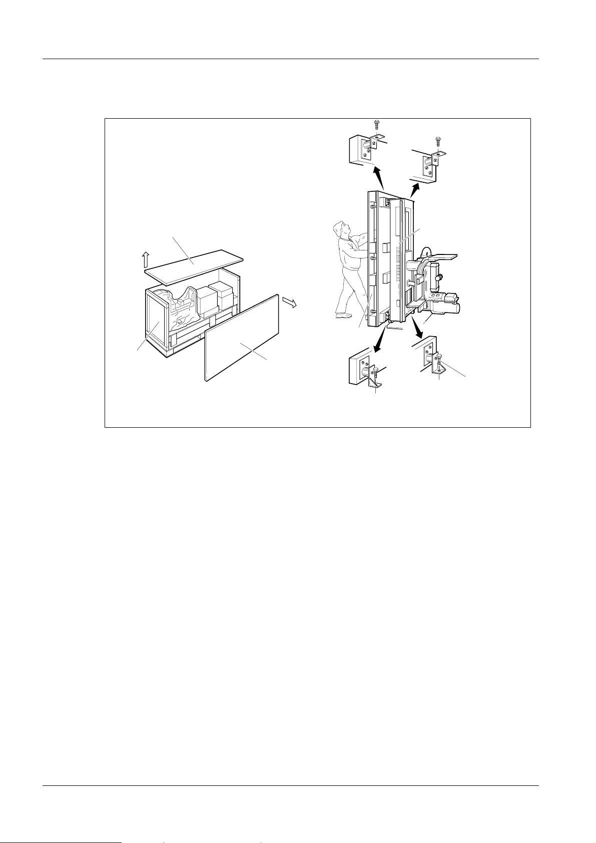
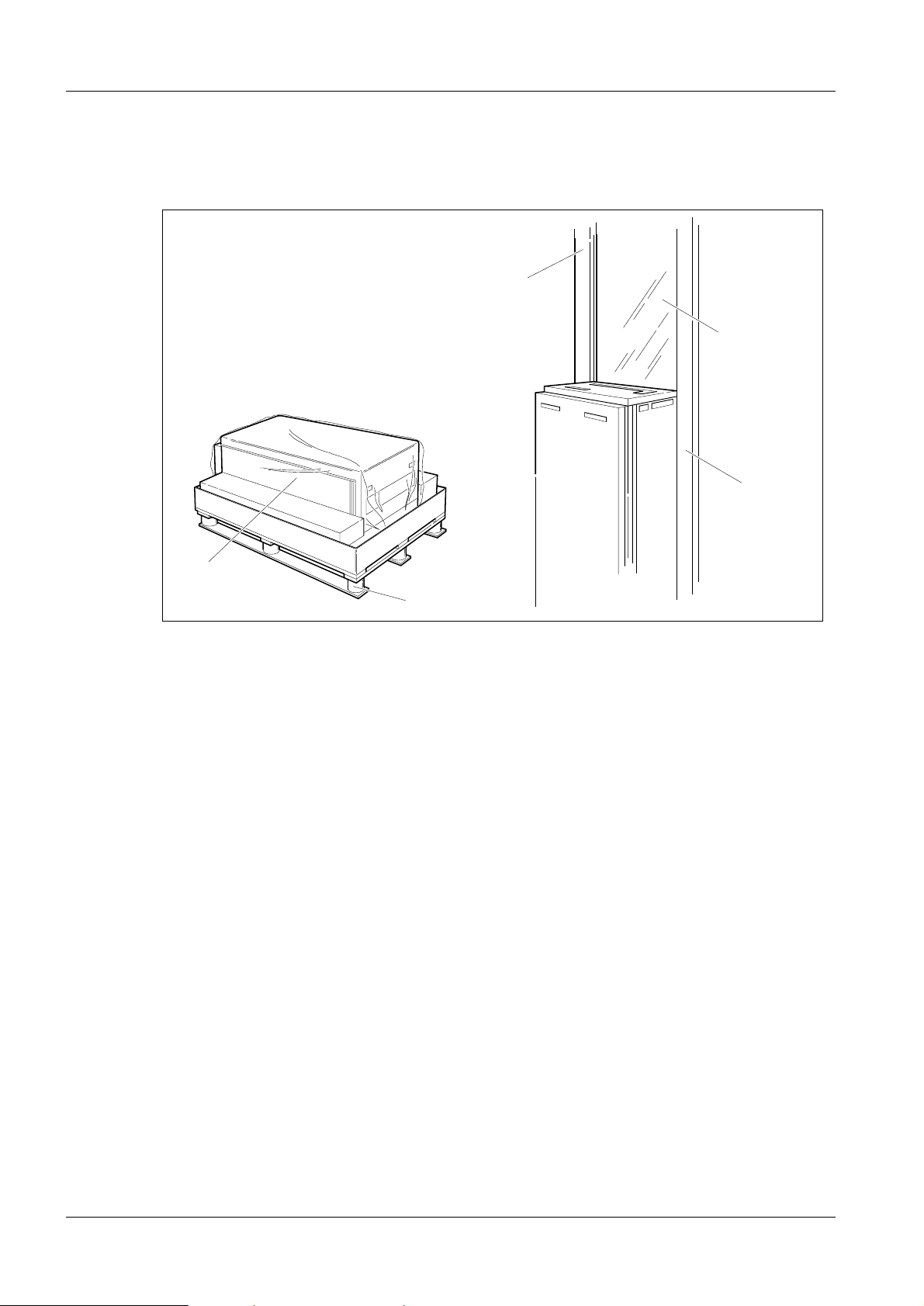
Unpacking the stand 3
1
3
Fig. 1 Unpacking the stand
1
2
5
2
4
6
Unpacking
1. Open the stand crate by removing the top (1) and then the side wall (2).
2. Take out all enclosed packages (accessor ies, installation material, cover panels
etc.) from the crat e.
MAM00167
3. Remove the wooden supports.
4. Remove the remaining walls (3 ).
5. Move the stand and pallet to the site of erection.
6. Upend the stand (4), with pallet (5) (two persons are required).
7. Loosen the four bolts (6) and remove the pa llet (5).
Mammomat 1000/3000 Register 03 SP B7-230.033.07 Page 2 of 8 Siemens-Elema AB
Installation and Start-Up Rev. 03 11.99 SPS-UD Solna, Sweden
Page 17
Preparatory work 3 - 3
NOTICE
Removing the transport safeguards 3
Removing the swivel-arm system transport safeguard 3
1
2
3
MAM00081
Fig. 2 Swivel-arm system transport safeguard
1. Loosen the transport safeguard nuts ( 1/Fig. 2) and remove the tube head scr ews
(2/Fig. 2).
2. Push the red transport safeguard (3/Fi g. 2) inwards, away from the tube head.
Removal of the swivel-arm system transport safeguard is done
after the equipment has been powered up, see further section
"Attaching the swivel-arm covers" on page 7 - 1.
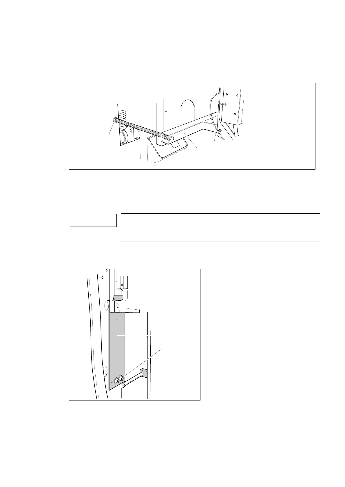
Transport safeguard for the lifting carriage 3
2
1
MAM00082
Fig. 3 Transport safeguard for the lifting carriage
1. Loosen the two screws (1/Fig. 3) and remove the red transport safeguard (2/ Fi g.
3). Reinsert screws (1/Fig. 3), they might be needed for service purposes.
Siemens-Elema AB Register 03 SP B7-230.033.07 Page 3 of 8 Mammomat 1000/3000
Solna, Sweden Rev. 03 11.99 SPS-UD Installation and Start-Up
Page 18
3 - 4 Preparatory work
NOTICE
MAM00312
The lifting carriage transport safeguard shall be kept for service
purposes (Fig. 5).
2. Cut and remove the cable tie securing the balancing spring during transport.
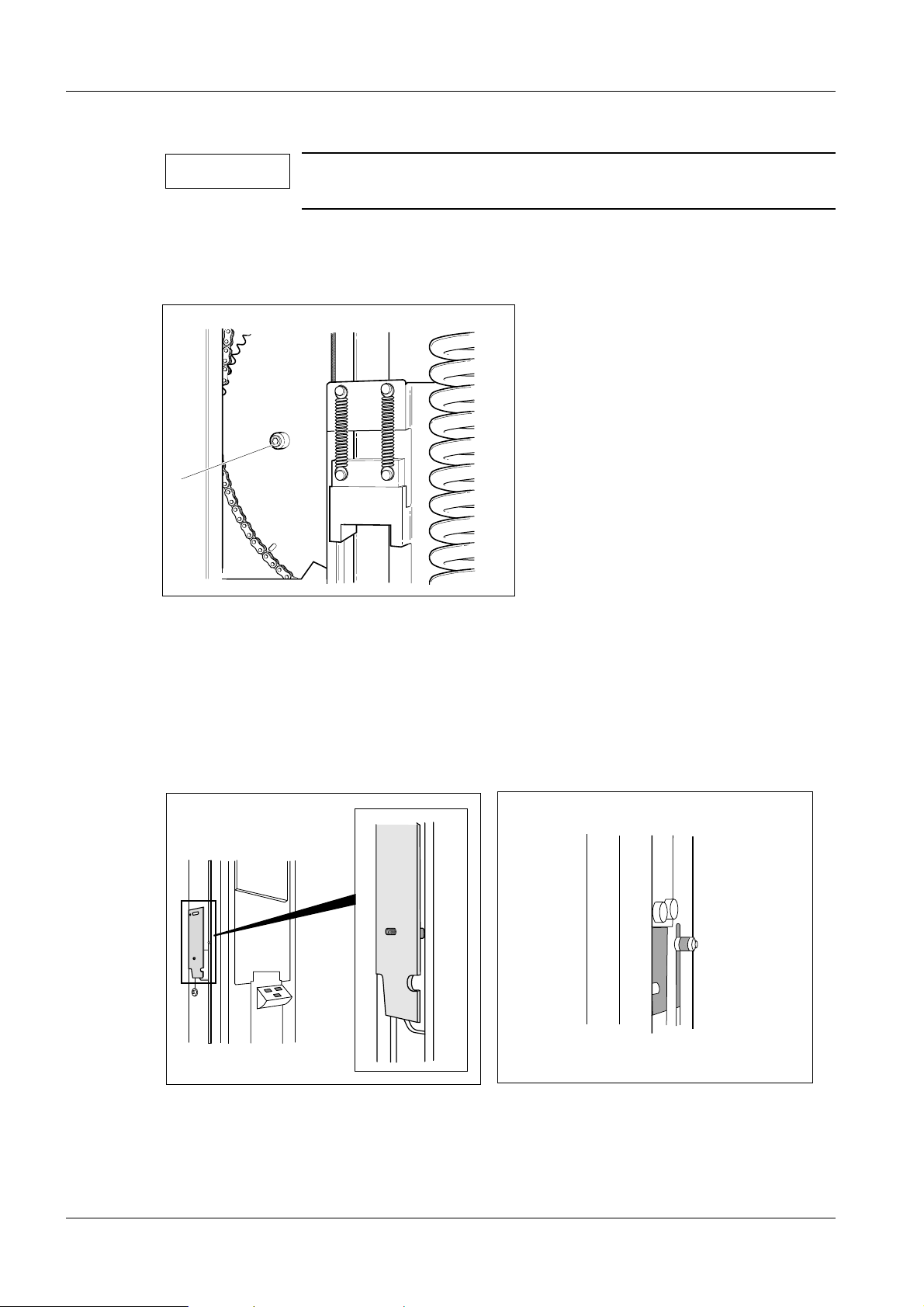
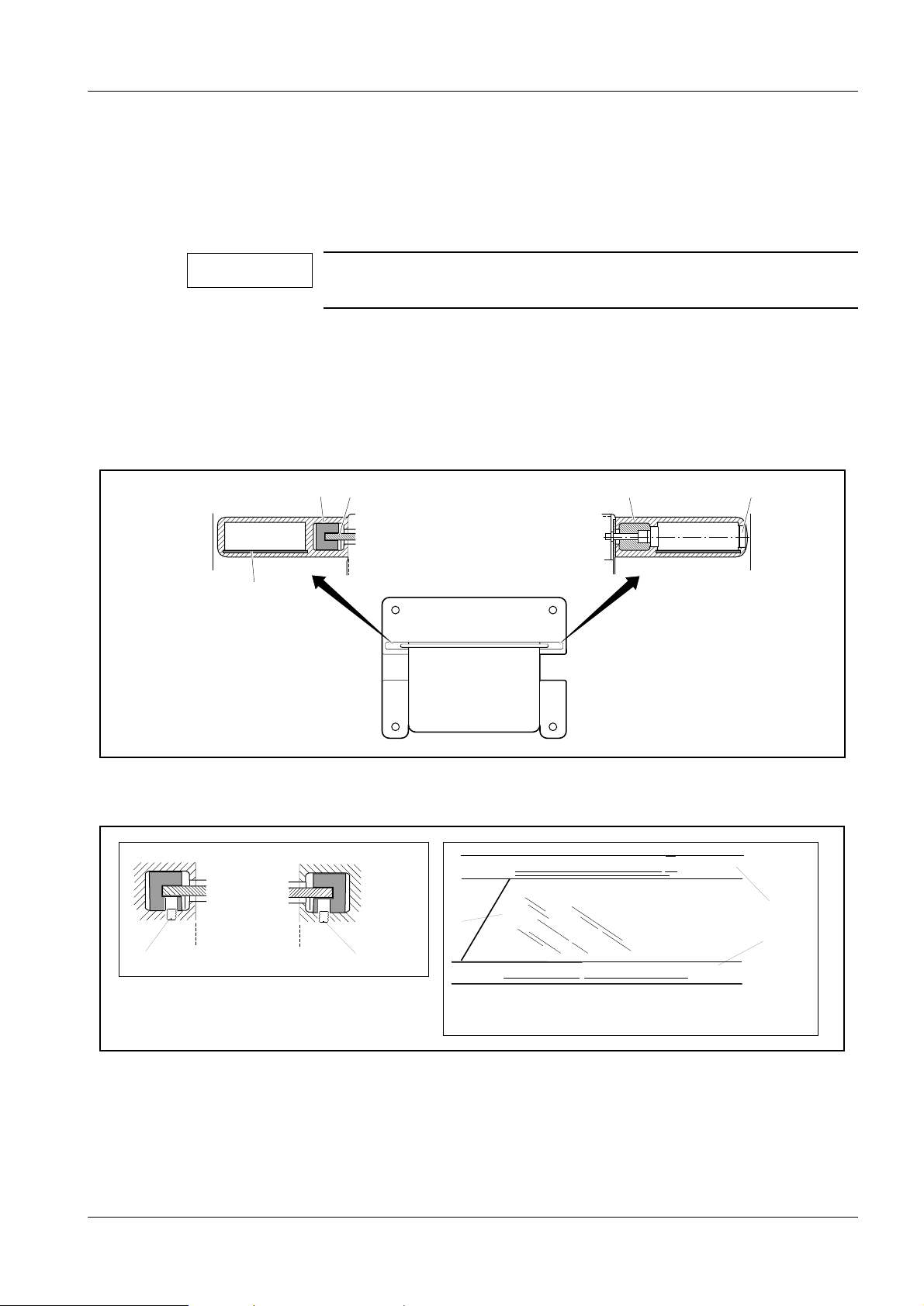
Transport safeguard for the rotary motion 3
1
MAM00083
Fig. 4 Transport safeguard for the rotary motion
1. Remove the transport safeguard screw (1/F ig. 4) with spacer to enable rotary
motion.
The screw and the spacer should be kept for the mounti ng of the lifting carriage
transport safeguard.
2. Mount the red lifting carriage t ransport safeguard with screw and spacer
(1/Fig. 4) on the left hand side of the stand, see Fig. 5. Insert the screw through the
slot from the inside of the sta nd, see Fig. 6
MAM00314
MAM00313
Fig. 5 Transport safeguard mounted on the stand Fig. 6 Screw and spacer inserted from the inside of the
stand
3. Tighten the screw. Make sure that the transport safeguard is parallell to the
stand.
Mammomat 1000/3000 Register 03 SP B7-230.033.07 Page 4 of 8 Siemens-Elema AB
Installation and Start-Up Rev. 03 11.99 SPS-UD Solna, Sweden
Page 19
Preparatory work 3 - 5
CAUTION
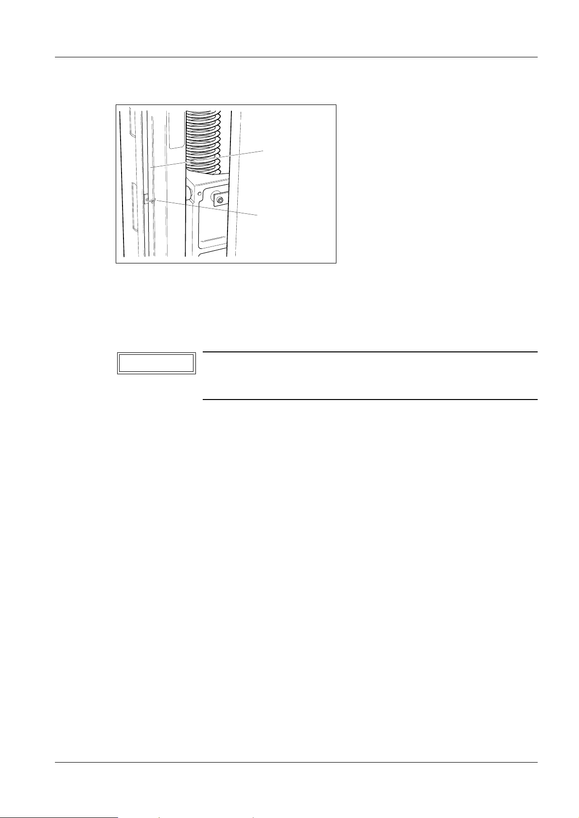
Protective strips for the metal curtain 3
1
2
MAM00084
Fig. 7 Protective strips for the metal curtain
The edges of the metal curtain are very sharp and are therefore provided with protective
strips (1) on delivery. These strips must always be ap plied onto the edges of the metal
curtain during service and maintenance work.
The protective strips must be removed from the metal curtain
before any vertical adjustment of the swivel-arm system is
performed.
Holders (2) for storing the protective strips when n o t in use, are provided on both si des of
the curtain, see Fig. 7.
Siemens-Elema AB Register 03 SP B7-230.033.07 Page 5 of 8 Mammomat 1000/3000
Solna, Sweden Rev. 03 11.99 SPS-UD Installation and Start-Up
Page 20
3 - 6 Preparatory work
Unpacking the generator and mounting the radiation shield
(optional)
1
3
3
4
3
2
MAM00085
Fig. 8 Unpacking the generator
1. Open the cardboard box by cutting the plas tic straps.
2. Lift out the lead-glass and put it away in a safe place.
3. Remove the protective cover from the generat or.
4. Upend the generator (1/Fig. 8) and lift i t off the pallet (2/Fig. 8) ( two persons are
required).
Mammomat 1000/3000 Register 03 SP B7-230.033.07 Page 6 of 8 Siemens-Elema AB
Installation and Start-Up Rev. 03 11.99 SPS-UD Solna, Sweden
Page 21
Preparatory work 3 - 7
NOTICE
➪ Optional:
5. Insert sheet-metal strip (5/Fi g. 9) (additional radiation prot ection) into both
stanchions.
6. Fit the lead-glass (4/Fig. 9) into both vibration absorbing stri p (6/Fig. 9) and fix it
softly by screws (1/Fig. 10).
The screws must be mounted before the lead-glass is inserted in
the stanchions.
7. Fit the lead-glass (2/Fig. 10) into the groove of one of the stanchions (3 /Fig. 10)
and keep it in position while mounting t he other stanchion (3 /Fig. 10).
8. Mount the stanchions and lead-glass unit wi th 6 screws onto the generator (3, 4 /
Fig. 8) (two persons are required ).
9. Cover the holes with plastic caps (7/F ig. 9).
6
5
Fig. 9 Mounting the radiation shield
3
74
MAM00086
3
2
1
1
MAM00630
3
MAM00633
Fig. 10
Siemens-Elema AB Register 03 SP B7-230.033.07 Page 7 of 8 Mammomat 1000/3000
Solna, Sweden Rev. 03 11.99 SPS-UD Installation and Start-Up
Page 22

3 - 8 Preparatory work
This page intentionally left blank.
Mammomat 1000/3000 Register 03 SP B7-230.033.07 Page 8 of 8 Siemens-Elema AB
Installation and Start-Up Rev. 03 11.99 SPS-UD Solna, Sweden
Page 23
Installing the generator and the stand 4
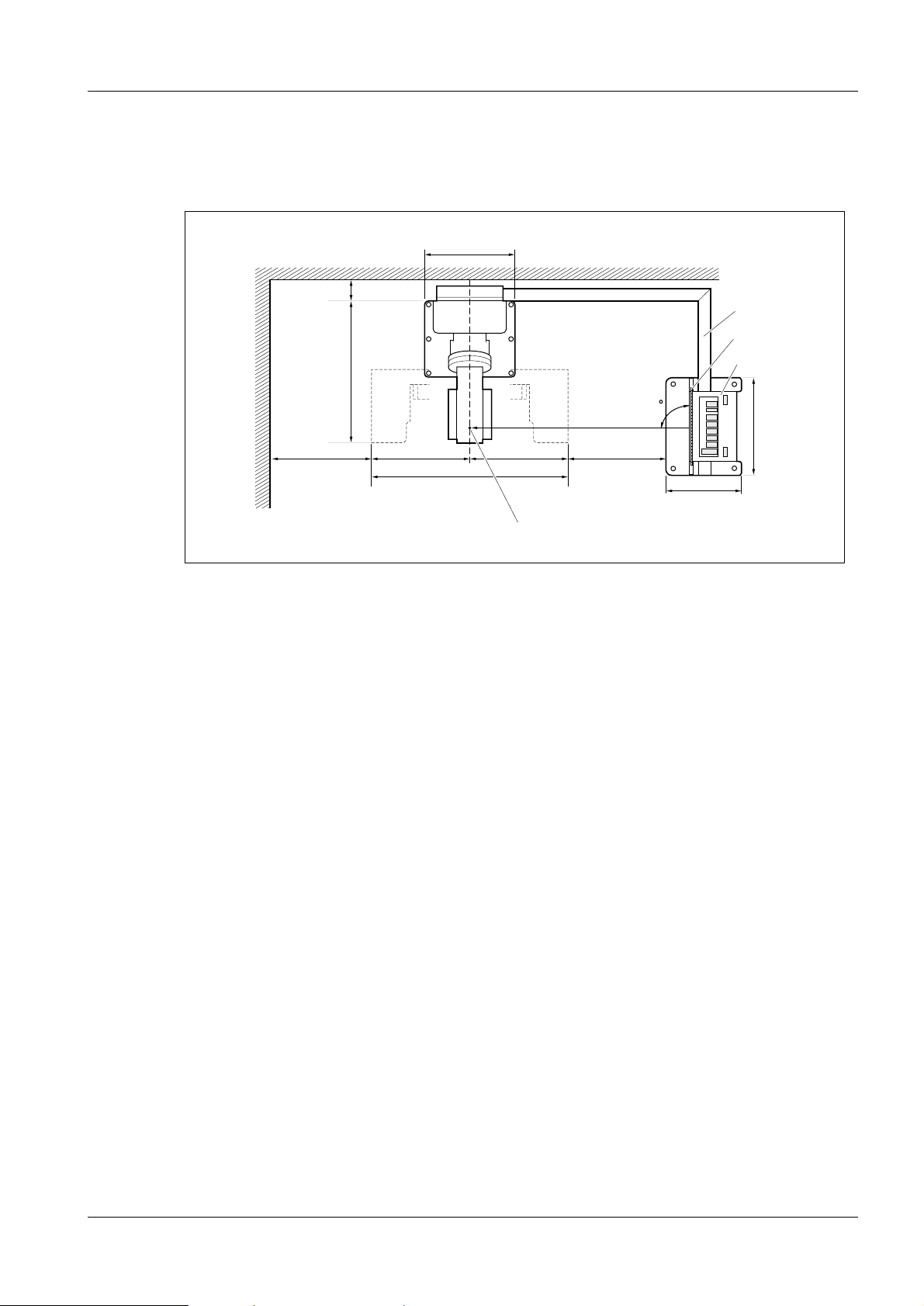
Arranging the components 4
Position the stand and the generator in accor dance with inst alla ti on plan and Fi g. 1 below.
640
4 - 1
700
Fig. 1 Installation, top view
180
1091
700 700
1400
4
90
700
540
1
2
3
708
MAM00503
Cable duct (1) and generator (3) with radiation shield (2) can be instal led opt ionall y to the
left or to the right of the the stand. The cables can also be laid under floor. Maximum cable
length between stand and generator is approximately 3.5 m.
Radiation shield (2) at right angles to the swivel-arm system and centered to the focus
mark (4) on the tube-head cover according to Fig. 1.
Recommended minimum distance to wall and generator base plate respectively is
700 mm (shorter distances may be used at the customer´s desire, if in compliance with
local regulations).
For the installation of the cable duct, a minimum distance of 180 mm between wall and
stands is required.
Notes on installations with separate gene rator and separate cont rol console
- The separate genera tor can be installed in any suitable place. The maximum dist ance
of 3.5 m (maximum cable length) to the stand must be maintained, however. If
separately installed, the genera tor must be bolted to the floor alternati vely be attached
to the wall by means of wall brackets, see furt her Chapter 19 "Bolting the stand/
generator to the floor".
- The separate cont rol console can be installed in a suit able place (wall-mounted or
mounted on a table, for example in an adjacen t room with radiation-proof window), or
be mounted onto the free-standing radiation shield (option). The connect ion cable to
the generator measures 10 m.
4
Siemens-Elema AB Register 3 SP B7-230.033.07 Page 1 of 6 Mammomat 1000/3000
Solna, Sweden Rev. 03 11.99 SPS-UD Installation and Start-Up
Page 24
4 - 2 Installing the generator and the stand
NOTICE
Free-standing radiation shield (option) 4
For the installation of the free-standi ng radi ation shield, please refer to separate instructions enclosed with the radiation shiel d.
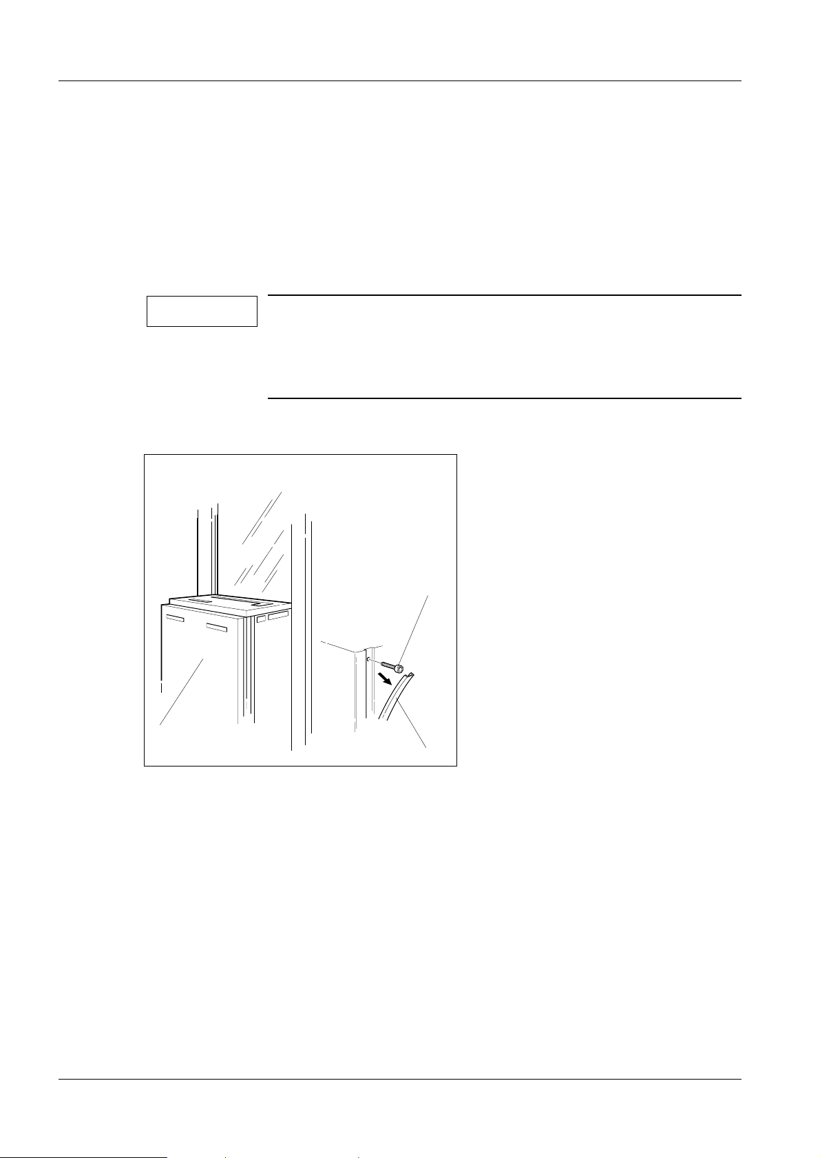
Removing the generator cover 4
1. Pry loose the plastic strip (1) and remove the sixteen screws (2), eight on eac h
side.
Pay special attention to the contact washers (there are four contact washers on either side). They are needed again when reassembling the front cover to establish protective ground
connection and to fulfil EMC (Electro Magnetic Compatibility)
requirements.
2. Remove the front cover (3) from the gener ator.
3
Fig. 2 Removing the generator cover
2
MAM00091
1
Mammomat 1000/3000 Register 3 SP B7-230.033.07 Page 2 of 6 Siemens-Elema AB
Installation and Start-Up Rev. 03 11.99 SPS-UD Solna, Sweden
Page 25
Installing the generator and the stand 4 - 3
NOTICE
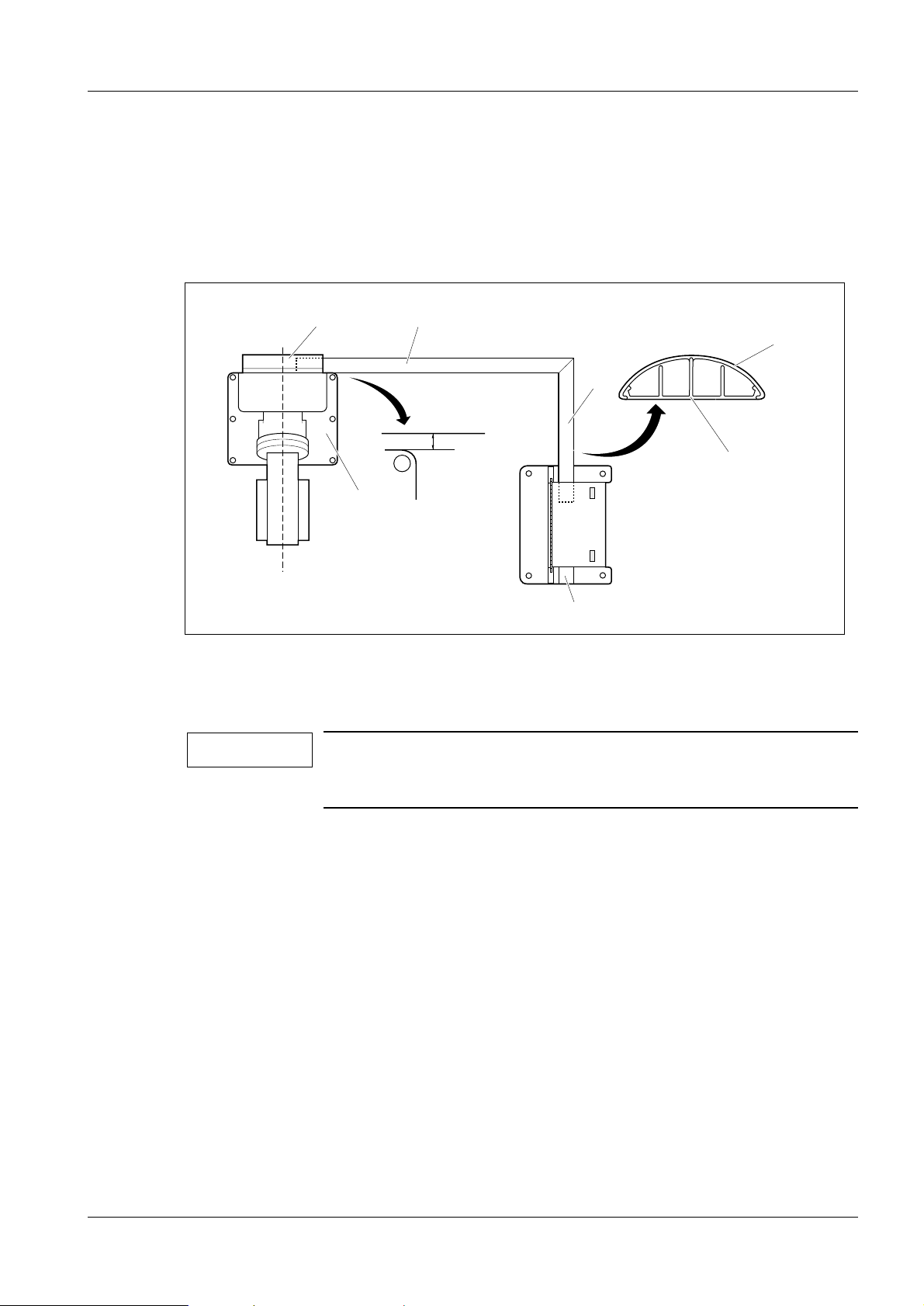
Installing the cable ducts 4
1. Position the cable ducts (1) to the stand and t he generator respectively.
2. Leave sufficient space, approx 10 mm between the cable ducts (1) and the base
plate of the stand (3) to allow for t he mounting of the cable outlet cover (4).
3. Check that the cable duct (1) is sligh tly overlapped by the cable outlet cover (4) .
4
3
Fig. 3 Installing the cable ducts (top view)
1
1
10 mm
6
7
1. Mark the outlines of the cable duct s (1) on the floor.
2. Cut the bottom of the cable ducts (6) and the cable duct cover (5) to proper lengt h.
Fig. 3 shows a right-angled installation of the cable ducts. If the
generator is to be inst alled at an other angl e to the s tand, you just
have to cut the cable ducts correspondingly.
5
MAM00089
3. Fasten the bottom plate of the cable ducts ( 6) to the floor according to marki ng,
using double-sided adhesive tape.
4. At the generator, cover the cable entry not used with the enclosed cover plate ( 7).
Installations with separate control console 4
For the connection cable separate control console – gener ator, additional cable duct s are
required, unless the cables are to be laid underfloor.
Siemens-Elema AB Register 3 SP B7-230.033.07 Page 3 of 6 Mammomat 1000/3000
Solna, Sweden Rev. 03 11.99 SPS-UD Installation and Start-Up
Page 26
4 - 4 Installing the generator and the stand
NOTICE
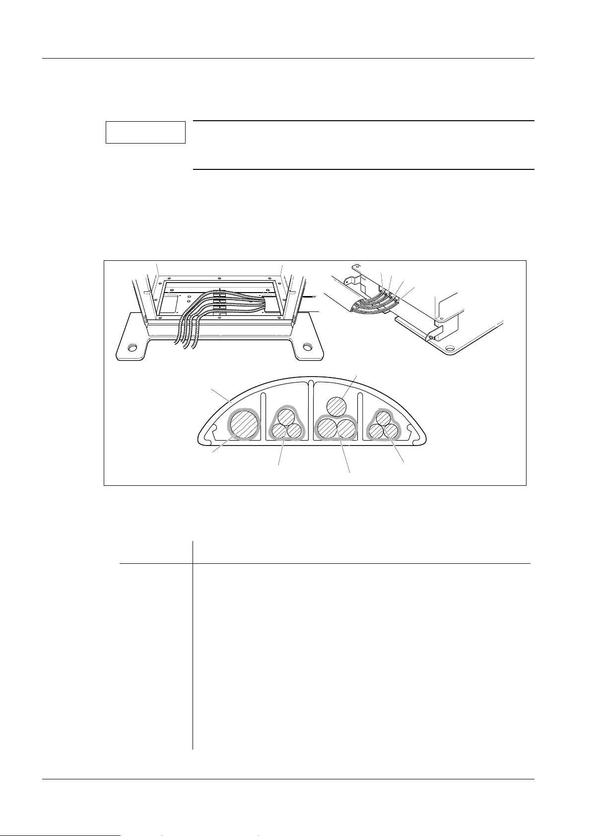
Laying the cable harness 4
Remove the transport safeguards which consist of cable ties
(four around the cable harness and one at the end of each
shielded cable).
1. Separate the cable harness.
2. Lay the stand cable harness in the cable duct, as shown in Fig. 4, all the way to the
generator.
3. Fit the cable duct covers (6) onto the c able ducts.
1
2
3
4
6
1
2
Fig. 4 Laying the cable harness
The cable harness consists of four shiel ded cables, see Fig. 4.
Pos in Fig. 4 Description
1 High voltage cable H1
2 IONTOMAT signal cables X10 and X11
Unit control cable X1
Power supply cable X14
MAM00092
5
MAM00215
4
3
3 Anode rotation cable X9
Filament cable X8
4 Mains supply cables L1, L2
Protective ground
5 Decompression-button cable (only with separate control consol e)
Mammomat 1000/3000 Register 3 SP B7-230.033.07 Page 4 of 6 Siemens-Elema AB
Installation and Start-Up Rev. 03 11.99 SPS-UD Solna, Sweden
Page 27
Installing the generator and the stand 4 - 5
Installations with separate control console 4
Lay the connecting cable from the control console in additional cable ducts, alternatively
underfloor, to the free cable entry of the generator, see further section Chapter 5 "Cable
connections" on page 5 - 8.
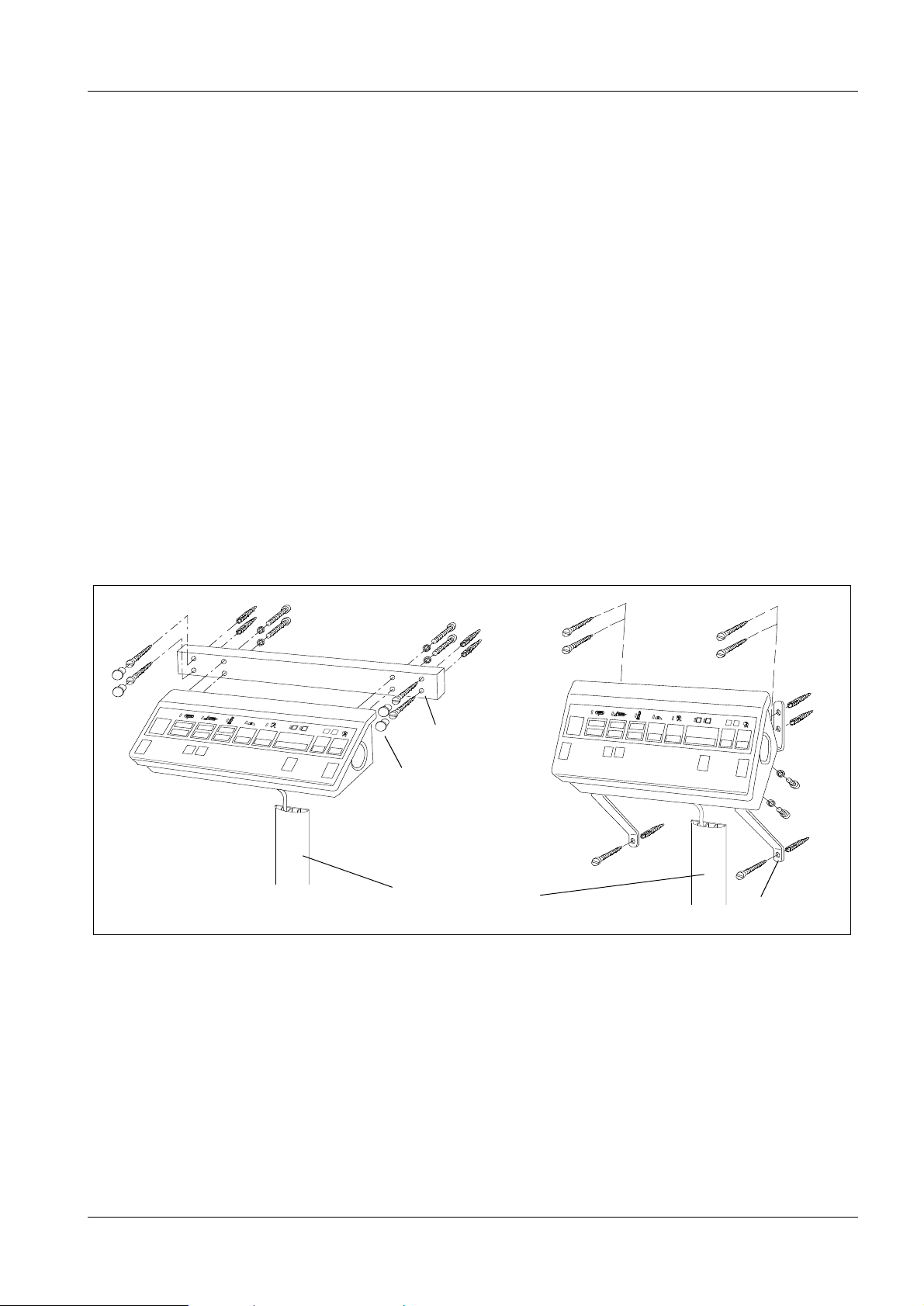
The separate control consol e can be wal l-mounted – hor izont ally o r v ertic ally as shown in
Fig. 5 below – or be mounted on a table, either in the examination room or in an adjacent
room with radiation-proof window. It is important that the control console be placed so that
the operator has good view of the patient from the control console.
Ensure that the control console is attached to the wall with a dequate safety mar gins. Dowels and screws are not supplied. Please obtai n th ese lo cally and ensure that they are sui table for the material used in the wall. The separate control console has a weight of 4 kg.
There are two cable outlets on the separate control console; one at the back and one on
the underside. On delivery, the cable is led through the outl e t at the back of the control
console. For wall-mounted contro l console, the cable shall be led t hrough the outl et on the
underside.
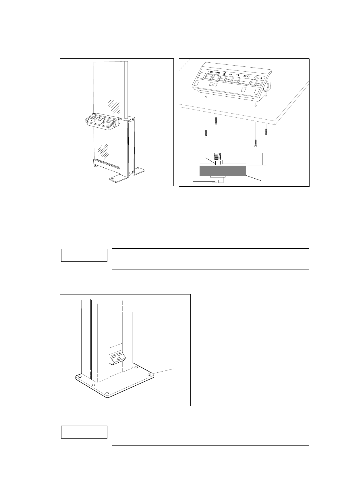
If the control console is to be mounted on a table, the minimum/maximum length of the
screws penetrating into the control console must be observed, see Fig. 7 below.
The control console can als o be mounted o n t he free- standin g ra diat ion shi eld ( opt ion) as
shown in Fig. 6 below, see separate instructions enclosed with the radiation shield.
MAM00168
Horizontal mounting
Fig. 5 Wall-mounted control console
6.5 mm
∅
Plastic cap
Wall-mounted cable duct
is recommended
Vertical mounting
6.5 mm
∅
MAM00169
Siemens-Elema AB Register 3 SP B7-230.033.07 Page 5 of 6 Mammomat 1000/3000
Solna, Sweden Rev. 03 11.99 SPS-UD Installation and Start-Up
Page 28
4 - 6 Installing the generator and the stand
NOTICE
NOTICE
MAM00171
<
min. 10 mm –
max. 30 mm
<
Table top
MAM00170
Fig. 6 Control console on free-standing radiation shield
(option)
Welded nut
M6
Fig. 7 Control console mounted on table
Aligning the stand 4
1. Align the stand vertically by means of the l evelling screws (1/Fig. 8) .
For adjustment of the levelling scr ews, use a ratchet spanner 1/2" with ex tension
(without socket).
It is important that all six screws bear against the floor to ensure
optimum stability of the stand.
2. Cover the levelling screws with the c over discs supplied.
1
MAM00090
Fig. 8 Levelling screws
If bolting to the floor is required, please refer to Chapter 19 "Bolting the stand/generator to the floor" on page 19 - 1.
Mammomat 1000/3000 Register 3 SP B7-230.033.07 Page 6 of 6 Siemens-Elema AB
Installation and Start-Up Rev. 03 11.99 SPS-UD Solna, Sweden
Page 29

Cable connection s 5
EMC measures 5
The following measures are required to ensur e electr omagnetic compat ib ili ty of the equipment.
EMC measures at the cable entry 5
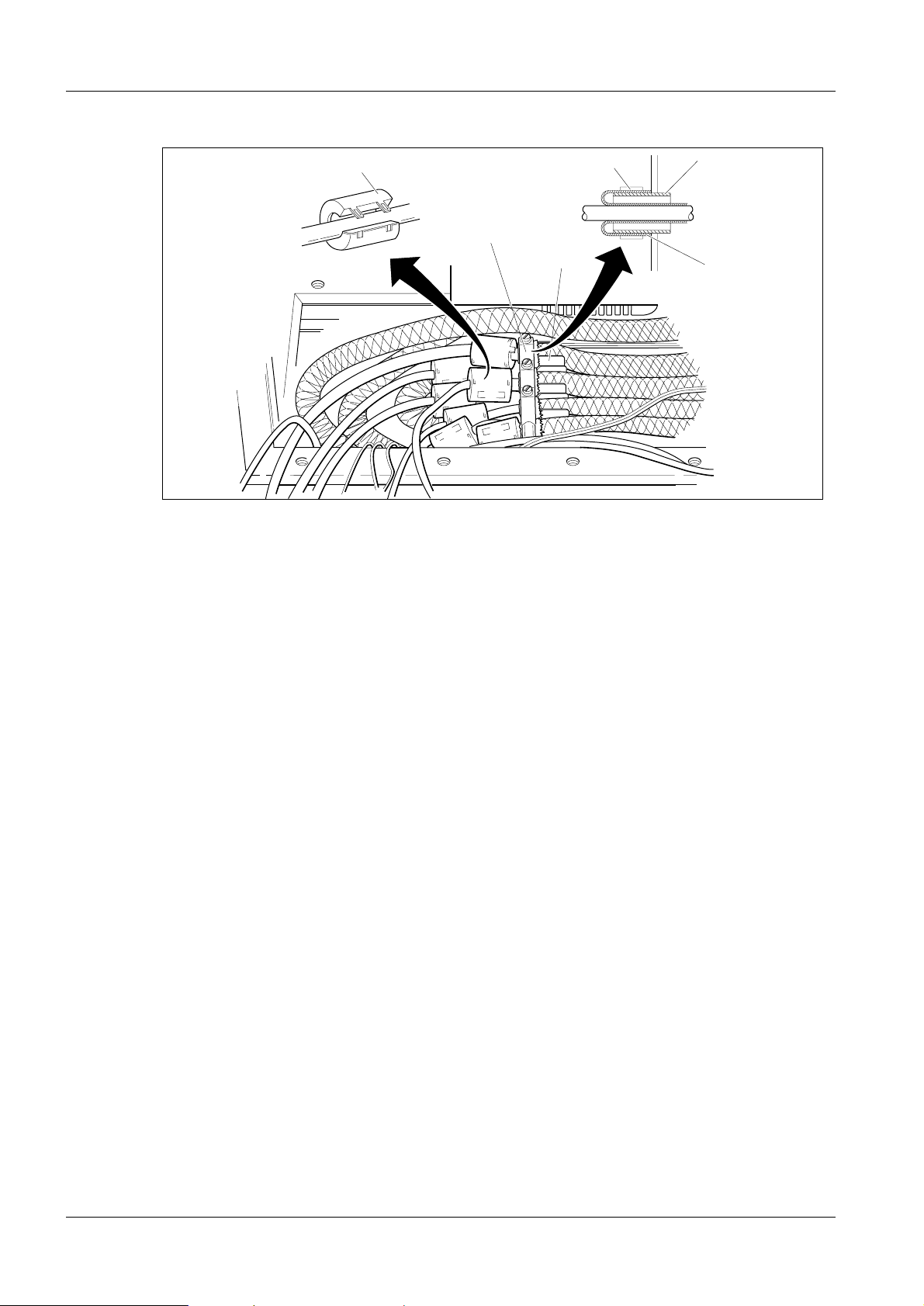
Fitting the hose clamps and ferrite sleeves
3cm
5 - 1
5
Fig. 1 Cables from the stand
1. Lay the cable harness from the stand to the generator and leave approximately
3 cm of the shielding at the U-bracket, see Fig. 1.
Stow away excessive cable lengths as shown in Fig. 2.
MAM00100
Siemens-Elema AB Register 3 SP B7-230.033.07 Page 1 of 14 Mammomat 1000/3000
Solna, Sweden Rev. 03 11.99 SPS-UD Installation and Start-Up
Page 30
5 - 2 Cable connections
4
Fig. 2 Ferrite sleeves and hose clamp
3
3
2
2
1
2. Provide each incoming cable with a ferrite sleeve (4), except for mains s upply
cables L1 and L2 and the ground wire, which shall be laid t ogether in one and the
same ferrite sleeve. Ferrite sl eeves are included in the delivery.
MAM00098
3. Provide each cable with a hose clamp (3). Hose clamps are included in the
delivery.
4. Fold the shield braid (1) backwards over the U-bracket (2) on each cable and
secure with the hose clamp (3).
Note on separate control console and separate generator 5
If the installation includes a separate control console and separat e generator , please refer
to page 5 - 8 for information on ho w to inst all the addi tional connecti on cable bet ween the
control console and the generator.
Mammomat 1000/3000 Register 3 SP B7-230.033.07 Page 2 of 14 Siemens-Elema AB
Installation and Start-Up Rev. 03 11.99 SPS-UD Solna, Sweden
Page 31

Cable connections 5 - 3
NOTICE
NOTICE
EMC measures on the bottom plate 5
Fitting the cables X1, X8 and X9 onto the bottom plate 5
3
Fig. 3 Bottom plate
4
2
1
1. Fit the bottom plate at the botto m of the generator stand as shown in Fig. 3.
2. Carefully cut away the insulation on c ables X1, X8 and X9 to lay bare the shield
braid (1).
3. Select proper clamps (2) with regar d to the thickness of the cables. Cable clamps
in different sizes are provided on t he bottom plate.
4. Fit the clamp (2) over the shiel d braid and screw tight to ensure satisf actory
contact between shield braid and cl amp.
5. Fasten the bottom plate with four sc rews (3) and contact washers (4).
Cable X9 shall also be clamped to the side wall of the cabinet, if
not already done, see Fig. 7 in this chapter.
MAM00099
Do not remove insulation and do not ground the shields of the
IONTOMAT signal cables to X10 and X11.
Siemens-Elema AB Register 3 SP B7-230.033.07 Page 3 of 14 Mammomat 1000/3000
Solna, Sweden Rev. 03 11.99 SPS-UD Installation and Start-Up
Page 32

5 - 4 Cable connections
NOTICE
Connecting the stand cable-harness 5
High-voltage connectors, alternative types 5
3
1
2
MAM00161
Type A
Fig. 4 High-voltage connector, alternative types
Type B
The high-voltage connector (1) is factory-adjusted for correct fit.
Mount the angular cable-sleeve halves and sleeve nut (Type B
only). The high-voltage connector shall be inserted wit h silicone
oil, silicone-rubber ring (2) and sili cone-r ubber disc (3) . Lubrica te
the silicone-rubber disc and the pins with silicon oil bef ore
mounting the disc. Make sure that there aren’t any air bubbles
between the disc and the connector.
3
1
2
MAM00093
Mammomat 1000/3000 Register 3 SP B7-230.033.07 Page 4 of 14 Siemens-Elema AB
Installation and Start-Up Rev. 03 11.99 SPS-UD Solna, Sweden
Page 33

Cable connections 5 - 5
Connecting the high-voltage connector 5
3
2
1
Type A Type B
Fig. 5 Connecting the high-voltage connector, alternative types
4
MAM00162
1
2
tillf00162
Type A
1. Plug in the high-voltage connector (1) at H1.
2. Tighten the sleeve nut (2) by hand.
3. Tighten the stop screws on the sleeve nut.
4. Position the high-voltage cable (3 ) to the right in the generator an d fasten with
cable ties (4).
3
4
MAM00243
Type B
1. Plug in the high-voltage connector (1) at H1.
2. Tighten the sleeve nut (2) by hand.
3. Position the high-voltage cable (3 ) to the right in the generator an d fasten with
cable ties (4).
Siemens-Elema AB Register 3 SP B7-230.033.07 Page 5 of 14 Mammomat 1000/3000
Solna, Sweden Rev. 03 11.99 SPS-UD Installation and Start-Up
Page 34

5 - 6 Cable connections
NOTICE
NOTICE
Connecting the cable harness to the generator 5
Required EMC measures are described on page 5 - 1 in this chapter.
2
1
6
5
Fig. 6 Cable harness at the generator
F10 F20
F1
F2
F3
F4
F5
3
4
7
MAM00165
MAM00165
Unit control cable X1 5
1. Connect the unit control cable X1 to D700 X1 (1).
Filament cable X8 5
1. Connect the filament cable X8 to D700 X8 (2).
Power supply cable X14 5
1. Connect the power supply cable X14 to D711 X14 ( 3).
2. Strain-relieve it on the side wi th a cable tie (4).
IONTOMAT signal cable X10 and X11 5
The Iontomat signal cable consists of two cables laid together as
one cable with two connectors labeled X10 and X11 at the end of
the cable.
1. Connect the IONTOMAT signal cable connectors, X10 and X11, to D700 X10 ( 5)
and X11 (6).
Mammomat 1000/3000 Register 3 SP B7-230.033.07 Page 6 of 14 Siemens-Elema AB
Installation and Start-Up Rev. 03 11.99 SPS-UD Solna, Sweden
Page 35

Cable connections 5 - 7
CAUTION
Rotating anode cable X9 5
2
4
3
1
MAM00163
Fig. 7 Connecting X9 to the generator
1. Connect the rotating anode cable X9 to D711 X9 (1 ).
2. Connect the two blue free wires from connector D711 X9 (1) to capacitor C51 (2).
3. Clamp the cable to the chassis with a cable cl amp (3).
When fitting the cable clamp, ensure satisfactory contact
between shield braid (4) and chassis.
Siemens-Elema AB Register 3 SP B7-230.033.07 Page 7 of 14 Mammomat 1000/3000
Solna, Sweden Rev. 03 11.99 SPS-UD Installation and Start-Up
Page 36

5 - 8 Cable connections
NOTICE
MAM001 2
Installations with separate control console and separate generator
MAM00166
Connection cable from separate control console
5
Fig. 8 Connection cable from separate control console
Shielding the cable from the separate control console as
described below is an absolute demand to comply with the EMC
regulations.
1. Lay the connection cable from the separate control consol e in additional cable
ducts, alternatively under floor, to t he f ree cabl e entry of the gener ato r, see Fig. 8.
2. Lay the connection cable in a free U-bracke t. Fold the shield braid over the
U-bracket and secure with a hose clamp as shown i n Fig. 9.
MAM00173
Fig. 9 Shielding the control console cable
Mammomat 1000/3000 Register 3 SP B7-230.033.07 Page 8 of 14 Siemens-Elema AB
Installation and Start-Up Rev. 03 11.99 SPS-UD Solna, Sweden
MAM00172
Page 37

Cable connections 5 - 9
F
3. Shield the control console cabl e to the bottom plate of the generator as shown i n
Fig. 10.
4. Provide the cables with ferrite sleev es. Cables X5 and X32 can be laid together in
one ferrite sleeve, X30 and the decompres sion-button cable in another sleeve
(two extra ferrite sleeves are i ncluded in the delivery). Plug together the decompression button cables. Shiel d the decompression button cable to t he bottom plate
, see Fig. 10. Lay the decompressio n button cable in the cable duct, alter -natively
underfloor, to the stand, see Fig. 4 i n Chapter 4 "Installing the generator and the
stand".
X5, X32
Ground wire
Fig. 10 Cables from separate control console
X30
Decompression
button cable
5. Connect X5 and X32 to the corresponding sockets on cir cuit board D700, X30 to
connector T3/X30 at the side of t he circuit board chassis. Connect the ground wire
to the protective ground termin al below fuse F10, see Fig. 11.
3
F4
F5
MAM00174
Protective
F10 F20
X32 X5 T3/X30
Fig. 11 Connecting the cables from the separate control console
Siemens-Elema AB Register 3 SP B7-230.033.07 Page 9 of 14 Mammomat 1000/3000
Solna, Sweden Rev. 03 11.99 SPS-UD Installation and Start-Up
ground
MAM00164
Page 38

5 - 10 Cable connections
NOTICE
6. Shield the decompression button cable to the stand chassis as shown in Fig. 12.
Connect to terminals 2 and 3 in terminal block X803 on the inside of the stand
chassis, see Fig. 12.
Fig. 12 Connecting the decompression button cable at the stand
1
Z801
2
1
23
X880
4
X885
MAM00175
Main voltage connection 5
The equipment has been set to 400 V, 2-phase, in the factory (see test certificate).
Adjustment to the line frequency is not needed. If the mains volt age is not 400 V, 2-p hase
at the installation site, a reconnection of the mains is necessary.
Should a reconnection for the mains voltage be necessary, this must be done at transformer T10 as well as p.c. board D711 (insertion or removal of fuses and labeling is specified in the wiring diagram, see Line Input page 5-3).
Change the rated voltage labels to the correct voltage (there are two labels on the generator and one on the stand). Labels are included in the install ation material.
For more details about changing mains, insertion or removal of
jumpers, fuses, labeling etc, see Wiring Diagram.
Mammomat 1000/3000 Register 3 SP B7-230.033.07 Page 10 of 14 Siemens-Elema AB
Installation and Start-Up Rev. 03 11.99 SPS-UD Solna, Sweden
Page 39

Cable connections 5 - 11
Connecting the incoming mains to the stand (400 V, 2-phase) 5
400 V 2-phase connection 5
N
L1
L2
L3
1
2
1
1
4
3
1
Fig. 13 Incoming mains cable
1. Connect the incoming mains cable (1) to X899 (2) in the stand as shown in Fig. 13
and Fig. 14.
2. Fit plastic tubes (4) on the plates.
3. Strain-relieve (3) the i ncoming mains cable.
TWO-PHASE
GENERATOR STAND
F10
F20
X881
Incoming mains
208, 230, 240, 277 or 400 VAC
P.ENL1L2L3
X899
MAM00097
MAM00095
Fig. 14 Incoming mains, 2-phase
Siemens-Elema AB Register 3 SP B7-230.033.07 Page 11 of 14 Mammomat 1000/3000
Solna, Sweden Rev. 03 11.99 SPS-UD Installation and Start-Up
Page 40

5 - 12 Cable connections
Connecting the mains supply to the generator (400 V, 2-phase) 5
F1
Fig. 15 Mains supply to the generator
F10 F20
F2
F3
F4
F5
2
1
3
MAM00176
1. Check that there is no wire jumper at F2 0 (1) and no brass plug at F5 (2).
Fuses must be inserted into fuse holde rs F20 and F5.
2. Connect the mains supply cables between stan d and generator to fuses F10 and
F20 on the generator.
Wire marked L1 to F10 and L2/N to F20.
3. Connect the protective ground wire fr om the stand to the generator (3).
Mammomat 1000/3000 Register 3 SP B7-230.033.07 Page 12 of 14 Siemens-Elema AB
Installation and Start-Up Rev. 03 11.99 SPS-UD Solna, Sweden
Page 41

Cable connections 5 - 13
CAUTION
NOTICE
Measures for changing from 2-phase to 1-phase connection 5
SINGLE PHASE
GENERATOR STAND
F10
X881
Fig. 16 Incoming mains, 1-phase
Incoming mains
110, 208, 230, 240 or 277 VAC
P.ENL1L2L3
X899
MAM00096
1. Move wire marked N/L2 from X899 L2 to X899 N (stand).
2. Connect incoming phase of the power supply to L1 and the neutral conductor of
the power supply (0 V) to N and fuse F20.
3. Strain-relieve the incoming main s cable as shown in Fig. 13.
4. Short circuit F20 (1) and F5 (2) in Fi g. 15 with the jumper and brass plug included
in the service bag.
For single-phase mains connection, make sure that the neutral
conductor of the power supply (0V) is connected to terminal N
and fuse F20.
Connections on transformer T10 must be adapted to the actual
mains voltage, see Wiring Diagram for details.
5. Connect the mains supply cable between s tand and generator to fuses F10 and
F20 on the generator. Wire marked L1 to F10 and L2/N t o F20.
Siemens-Elema AB Register 3 SP B7-230.033.07 Page 13 of 14 Mammomat 1000/3000
Solna, Sweden Rev. 03 11.99 SPS-UD Installation and Start-Up
Page 42

5 - 14 Cable connections
This page intentionally left blank.
Mammomat 1000/3000 Register 3 SP B7-230.033.07 Page 14 of 14 Siemens-Elema AB
Installation and Start-Up Rev. 03 11.99 SPS-UD Solna, Sweden
Page 43

Mains connection and power supply 6
Checks before powering up the generator 6
On P.C. board D702:
1. Set switch S1(UZW) to "OFF" (lower positi on).
2. Set switch S2 (SS) to "OFF" (lower position)
.
6 - 1
ZBL
AR
KVE
BRAKE
STATUS
UZW
SS
TEST
V6
V7
V1
V2
V3
V4
V5
VH
NSE1
NSE2
DS
SS
BS
GND
X990
X967
X980
X981
X982
X983
X984
X985
S1
S2
S3
J39
X962
X964
X960
R13
R11
R43
J50
X965
X961
X963
IHREG
MAREG
X966
X968
X969
X702
MAM00106
Fig. 1 P.C. board D702
Measuring the line resistance 6
See Fig. 2.
1. Remove fuses F10 (1) and F20 (2) or, when sin gle-phase supply, fuse F10 (1).
2. Connect line resistance meter to fu se holders F10 and F20.
3. Mains supply "ON".
4. Carry out measurement.
5. Mains supply "OFF".
Siemens-Elema AB Register 3 SP B7-230.033.07 Page 1 of 4 Mammomat 1000/3000
Solna, Sweden Rev. 03 11.99 SPS-UD Installation and Start-Up
Page 44

6 - 2 Mains connection and power supply
To achieve the full output, the resistance measured must not exceed the following values:
• 0.25 c at 110 V (1-phase)
• 0.45 c at 208 V
• 0.50 c at 230 V
• 0.60 c at 240 V
• 0.65 c at 277 V
• 0.85 c at 400 V (2-phase)
If the above values are exceeded, reduce the generator power in accordance to Chapter
13 "Checking the swivel-arm system" in this manual.
Checking the line voltage in the generator 6
1. If not already done, remove fuses F10 (1) and F20 (2) or, when single-phase
supply, fuse F10 (1).
4
5
6
1
2
3
Fig. 2 Line voltage in the generator
2. Mains supply "ON".
3. Measure the voltage at fuse holders F10 ( 1) and F20 (2).
4. Check that the mains voltage agrees with the v oltage plugged on transformer T10
(3) and P.C. board D711 (4), located above line f ilter Z1 (5).
5. Mains supply "OFF".
MAM00177
6. Reinsert fuses F10 (1) and F20 (2).
7. Mains supply "ON" (Do not switch the system on yet).
8. Measure the voltage at transformer T1 (6) terminals 1 and 3, transformer T1 is
located under the line filter Z1 (5). There must be 195 V- 253 V between the
terminals.
9. Measure the voltage at the output of lin e filter Z1 it must lie within 195 V- 264 V.
Mammomat 1000/3000 Register 3 SP B7-230.033.07 Page 2 of 4 Siemens-Elema AB
Installation and Start-Up Rev. 03 11.99 SPS-UD Solna, Sweden
Page 45

Mains connection and power supply 6 - 3
Checking the supply voltages 6
The correct supply voltages +5 V, +15 V and +24 V have already been tested in the factory. Only a visual check of the function is therefor e needed.
1. System "ON".
2. Check that the following orange dio des are "ON" on p.c. board D704:
V39 (+15 V)
V38 (-15 V)
V41 (+5 V)
V40 (+24 V)
Siemens-Elema AB Register 3 SP B7-230.033.07 Page 3 of 4 Mammomat 1000/3000
Solna, Sweden Rev. 03 11.99 SPS-UD Installation and Start-Up
Page 46

6 - 4 Mains connection and power supply
This page intentionally left blank.
Mammomat 1000/3000 Register 3 SP B7-230.033.07 Page 4 of 4 Siemens-Elema AB
Installation and Start-Up Rev. 03 11.99 SPS-UD Solna, Sweden
Page 47

Attaching the swivel-arm covers 7
Attaching the swivel-arm covers 7
Arranging the swivel-arm system 7
1. Remove the cable tie securing the balanc ing spring at the back of the stand.
2. Install object table, no compressi on force (swivel-arm system still ups ide down).
3. Remove the protective strips from the meta l curtain.
4. Run the lifting carriage upwards.
5. Put back the protective strips onto t he metal curtain.
6. Rotate the swivel-arm system to 0 degre es by pressing one of the switches for
clockwise rotation on the supporti ng arm.
7. System and mains "OFF".
8. Remove the swivel-arm system transpo rt safeguard, see Chapter 3 "Preparato ry
work".
Connecting the cables to control-button boards and patient handles 7
7 - 1
MAMMOMAT 1000/3000
4
2
2
Fig. 1 Connecting the cables
Before installing the side covers, the cables are to be connected.
MAMMOMAT 1000/3000
1. Connect cables X807 (1) to control-butt on circuit boards D807 (2).
2. Connect ground wires (3) to patient handles (4).
1
1
4
3
3
MAM00108
Siemens-Elema AB Register 3 SP B7-230.033.07 Page 1 of 2 Mammomat 1000/3000
Solna, Sweden Rev. 03 11.99 SPS-UD Installation and Start-Up
Page 48

7 - 2 Attaching the swivel-arm covers
NOTICE
CAUTION
CAUTION
Attaching the side covers 7
Screws in different sizes are inc luded in the delivery.
5
4
Fig. 2 Covers and sign
2
1
1. Mount the side covers (1) with six screws (2) on each side.
Do not forget to fit the sign (3) when mounting the side covers.
Use the two longer screws.
3
MAM00178
Attaching the front cover 7
Because of the risk of damages, the following work must be carried out with caution. If the covers are exposed to internal stress
due to poor fit, cracks might arise.
1. The side covers must be flush at the front. If necessary, loosen the screws and
adjust the side covers.
2. Carefully fit the front cover (4) so that both openings engage with the lugs of the
side covers.
3. Carefully swing the front cover upwards and l et it snap in position over the side
covers.
The front cover must not press against the collimator (risk of
damage).
4. Fasten the front cover to the side covers with two short screws (5).
Mammomat 1000/3000 Register 3 SP B7-230.033.07 Page 2 of 2 Siemens-Elema AB
Installation and Start-Up Rev. 03 11.99 SPS-UD Solna, Sweden
Page 49

Checking the microprocessors 8
Microprocessors 8
The following LED displays on the processor P.C. boards indicate whether the relevant
microprocessors are operating correctly.
1. Mains and system "ON".
The following conditions must be indi cated after not more than 15 s.
8 - 1
Microprocessors for:
Master: P.c. board D702
IONTOMAT PM: P.c. board D701
P.C. board D711:
• V9 "ON" (line voltage on).
• V13 "OFF" (system stand-by).
• V11 "ON" (system on).
• V16 "ON" (intermediate circuit - filament).
LED displays
Must be off.
Flashing rapidly.
Must be off.
Must be flashing
(2-3 Hz).
MAM00110
Siemens-Elema AB Register 3 SP B7-230.033.07 Page 1 of 2 Mammomat 1000/3000
Solna, Sweden Rev. 03 11.99 SPS-UD Installation and Start-Up
Page 50

8 - 2 Checking the microprocessors
This page intentionally left blank.
Mammomat 1000/3000 Register 3 SP B7-230.033.07 Page 2 of 2 Siemens-Elema AB
Installation and Start-Up Rev. 03 11.99 SPS-UD Solna, Sweden
Page 51

Checks without high voltage 9
NOTICE
Checks without high voltage 9
1. System "OFF".
2. On P.C. board D702 set switch S1 (UZW) to "ON" (upper p osition) and switch S2
(SS) to "OFF" (lower position).
3. System "ON".
4. Insert a cassette.
The cassette must be removed and reinserted after each
exposure to allow for the next exposure release. This is to avoid
double exposures.
5. Press the exposure buttons on the control panel . The rotating anode shal l start up.
At the end of the limit time, the rot ating anode is braked.
6. Release the exposure buttons.
7. System "OFF".
9 - 1
Siemens-Elema AB Register 3 SP B7-230.033.07 Page 1 of 2 Mammomat 1000/3000
Solna, Sweden Rev. 03 11.99 SPS-UD Installation and Start-Up
Page 52

9 - 2 Checks without high voltage
This page intentionally left blank.
Mammomat 1000/3000 Register 3 SP B7-230.033.07 Page 2 of 2 Siemens-Elema AB
Installation and Start-Up Rev. 03 11.99 SPS-UD Solna, Sweden
Page 53

Checks with high voltage 10
WARNING
NOTICE
Preparation 10
This section describes how to check:
• Radiographic voltage.
• Tube current.
• mAs values.
Radiation
Check that the high-voltage plug is plugged into H1 and properly
secured.
10 - 1
kV>17
V39
kV>50
V41
IHIST
UZIST
KVIST
0VA
KVE
KVA
ZBL
0VD
V40
X706
X707
X705
X704
X713
X710
X712
X711
X708
X714
X715
X716
X717
X709
R136
X703
WR_AUS
MASOLL
MAIST
IHSOLL
ISCHWING
KVSOLL
BRAKE
Fig. 1 P.C. board D705
1. Set switch S2 (SS) to "ON" (upper position) on P.C. board D702.
2. Remove the jumper and connect the mAs meter to mAs measuri ng sockets X3
and X4 on P.C. board D710.
MAM00111
Siemens-Elema AB Register 3 SP B7-230.033.07 Page 1 of 6 Mammomat 1000/3000
Solna, Sweden Rev. 03 11.99 SPS-UD Installation and Start-Up
Page 54

10 - 2 Checks with high voltage
NOTICE
NOTICE
NOTICE
3. Connect oscilloscope to P.C. board D705 as follows:
• Channel 1 to measuring point "KVIST(actual value)" (1 V= 5 kV).
• Channel 2 to measuring point "MAIST(actual value)" (1 V= 40 mA).
• Trigger at measuring point "KVE" (start with high volt age "ON"), rising edge.
• Twist the measuring leads and connect their grounding br aids to measuring
point "0 VA".
4. Connect service PC to circuit board D702 using th e connection cable.
Switch S3 on circuit board D702 must be set to upper position.
5. Start service program, see Chapter 20 "Append ix".
6. Check the anode menu for correct selecti on (tungsten anode enabled or disabled,
depending on which type of X-ray tube the customer has choosen). See Service
Program Instructions RX B7-230.114.0 1. ... .
It is possible to select tungsten anode, even if the customer does
not have this option. However, the 50 µm Rh filter will then be
missing.
Checking X-ray tube high voltage, tube currrent and mAs values10
1. System "ON".
2. Set the "cassette loaded" switch to " OFF" with the service PC program:
Configuration - Miscellaneous - Cassette loaded check.
3. Trigger test exposures with the following exposure values and check the kV
values and tube current characterist ic on the oscilloscope (see oscill ograms).
The accuracy of the kV is &5% plus &1.5 kV during the first 5 ms of the exposure.
For mA values < 50 mA, the accuracy of the kV is &5% plus &2 kV during the first
5ms.
The tube current must rise quickly to t he set value at the beginning of the exposure and run linearly during th e exposure, however, not when TCR is running.
The accuracy of the mAs product must be &10%.
4. Replace the jumper previously removed.
Tube current reduction 10
In MAMMOMAT, the tube current reduction is factory-set to "ON"
(see Chapter 12 "Further programming" and test certificate). In
this way, the tube current is reduced to approximately 50 mA at
the start of the exposure during the time programmed in Chapter
12 "Further programming". The tube current reduction is eff ective
only in IONTOMAT mode with Bucky.
Mammomat 1000/3000 Register 3 SP B7-230.033.07 Page 2 of 6 Siemens-Elema AB
Installation and Start-Up Rev. 03 11.99 SPS-UD Solna, Sweden
Page 55

Checks with high voltage 10 - 3
NOTICE
NOTE
Oscilloscope diagrams 10
• MAMMOMAT in mAs mode, see Fig. 2 - Fig. 9.
• MAMMOMAT with tube current reduction switched on, Iontomat mode with Bucky, see
Fig. 10 - Fig. 11.
• MAMMOMAT in Iontomat mode with tube current reduction switched off, see
Fig. 12 - Fig. 13.
Checks indicated by
filter disc Mo 0.03 / Rh 0.025 (molybdenum rotating anode).
Tube P40 MoW, MAMMOMAT 3000
* tungsten anode 0.3
30 kV 20 mAs (P = 4.7 kW)
* shall be disregarded in installations with
Tube P40 MoW, MAMMOMAT 1000/3000
molybdenum anode 0.3
30 kV 20 mAs (P = 3.75 kW)
?
MAM00179
Fig. 2 Fig. 3
30 kV 1 V/T (1 T <=> 5 kV) 30 kV 1 V/T (1 T <=> 5 kV)
?
MAM00112
158 mA 1 V/T (1 T <=> 40 mA) 125 mA 1 V/T (1 T <=> 40 mA)
127 ms 20 ms/T 160 ms 20 ms/T
Record the measured kV and mAs value in the measuring protocol, page 20 - 3.
Siemens-Elema AB Register 3 SP B7-230.033.07 Page 3 of 6 Mammomat 1000/3000
Solna, Sweden Rev. 03 11.99 SPS-UD Installation and Start-Up
Page 56

10 - 4 Checks with high voltage
Tube P40 MoW, MAMMOMAT 3000
* tungsten anode 0.3
35 kV 100 mAs (P = 4.7 kW)
MAM00180
Fig. 4 Fig. 5
Tube P40 MoW, MAMMOMAT 1000/3000
molybdenum anode 0.3
35 kV 100 mAs(P = 3.75 kW)
35 kV 1 V/T (1 T <=> 5 kV) 35 kV 1 V/T (1 T <=> 5 kV)
134 mA 1 V/T (1 T <=> 40 mA) 107 mA 1 V/T (1 T <=> 40 mA)
0.75 s 0.2 s/T 0.93 s 0.2 s/T
MAM00113
25 kV 100 mAs (P = 4.7 kW)
MAM00181
Fig. 6 Fig. 7
25 kV 100 mAs(P = 3.75 kW)
25 kV 1 V/T (1 T <=>5 kV) 25 kV 1 V/T (1 T <=> 5 kV)
188 mA 2 V/T (1 T <=> 80 mA) 150 mA 2 V/T (1 T <=> 80 mA)
0.53 s 0.1 s/T 0.67 s 0.1 s/T
MAM00114
Mammomat 1000/3000 Register 3 SP B7-230.033.07 Page 4 of 6 Siemens-Elema AB
Installation and Start-Up Rev. 03 11.99 SPS-UD Solna, Sweden
Page 57

Checks with high voltage 10 - 5
NOTICE
NOTICE
Tube P40 MoW, MAMMOMAT 3000
* tungsten anode 0.15
30 kV 10 mAs (P = 0.85 kW)
Tube P40 MoW, MAMMOMAT 1000/3000
molybdenum anode 0.15
30 kV 10 mAs (P = 0.70 kW)
?
MAM00182
Fig. 8 Fig. 9
30 kV 1 V/T (1 T <=> 5 kV) 30 kV 1 V/T (1 T <=> 5 kV)
28 mA 0.5 V/T (1 T = 20 mA) 23 mA 0.5 V/T (1 T <=> 20 mA)
360 ms 50 ms/T 430 ms 100 ms/T
>>
?
MAM00115
Small focus is selected by attaching a magnification table.
Record the measured kV and mAs value in the measuring protocol, page 20 - 3.
Siemens-Elema AB Register 3 SP B7-230.033.07 Page 5 of 6 Mammomat 1000/3000
Solna, Sweden Rev. 03 11.99 SPS-UD Installation and Start-Up
Page 58

10 - 6 Checks with high voltage
MAM00317
30 kV
Iontomat
(P = 4.7 kW)
40 mm plexiglass
Tube P40 MoW, MAMMOMAT 3000
* tungsten anode 0.3
30 kV
Iontomat w. grid
(P = 4.7 kW)
40 mm plexiglass
MAM00316
Fig. 10 Fig. 11
30 kV 1 V/T (1 T <=> 5 kV) 30 kV 1 V/T (1 T <=> 5 kV)
158 mA 1 V/T (1 T = 40 mA) 125 mA 1 V/T (1 T <=> 40 mA)
Tube P40 MoW, MAMMOMAT 1000/3000
molybdenum anode 0.3
30 kV
Iontomat w. grid
40 mm plexiglass
*) 100 ms /t *) 100 ms /T
(P = 3.75 kW)
MAM00315
Fig. 12 Fig. 13
30 kV 1 V/T (1 T <=> 5 kV) 30 kV 1 V/T (1 T <=> 5 kV)
158 mA 1 V/T (1 T <=> 40 mA) 125 mA 1 V/T (1 T <=> 40 A)
*) 100 ms /T) *) 100 ms /T
*) total exposure time dependent on programmed sensitivity
30 kV
Iontomat
40 mm plexiglass
(P = 3.75 kW)
MAM00318
Mammomat 1000/3000 Register 3 SP B7-230.033.07 Page 6 of 6 Siemens-Elema AB
Installation and Start-Up Rev. 03 11.99 SPS-UD Solna, Sweden
Page 59

Start-up and functional test of the IONTOMAT 11
NOTICE
NOTICE
Checking and programming with the service PC 11
Use the service PC to check and program the IONTOMAT.
Operation of the service PC is described in Chapter 20 "Appendix".
The tables in this kit are optimized for the foll o wing four film/screen combinations.
Table 1
11 - 1
Film
Kodak Min-RE
Fuji UM-MA HC
Agfa Mamoray MR6
Dupont Microvision C
Screen
Kodak Min-R
Fuji HR Mammo Fine
Agfa MR Detail S
Dupont Quantavision ME
Cassette
Kodak Min-R2
Fuji EC-MA
Agfa MR Detail S
Dupont Quantavision
Sensitivity
11
9.5
7
12
Correction
curve
A
B
C
D
Program the IONTOMAT values as follows:
If it is a M 3000 stand equipped with one "wing" only and counterweight, the programming for "wing 2" shall be omitted. If it is a
M 1000 stand, the programming is done for "base plate".
Sensitivity 11
Start with the sensitivi ty li sted i n the tabl e f or the film/ scr een combinat ion used by the customer. Program this values for "wing 1" and "wing 2" under H. If the customer uses one
more film/screen combination, program this value for "wing 1" and "wing 2" under D, otherwise program the same values as under H.
If the film/screen combination used by the customer is not listed in table 1, star t
with sensitivity 11.
MAM00185
Be sure to use the same type of cassette, screen and film in each
object table as the customer uses.
IONTOMAT PM - Sensitivity
Wing 1
Wing 2
Valid entries from 0 to 31 in 1/2 E.P.
Input of decimal point not required!
Help 2 Save 3 45678910Quit
1
Fig. 1
HD
11.0
11.0 11.0
11.0
Values from 0 to 31 can be entered.
Siemens-Elema AB Register 3 SP B7-230.033.07 Page 1 of 12 Mammomat 1000/3000
Solna, Sweden Rev. 03 11.99 SPS-UD Installation and Start-Up
MAM00186
Page 60

11 - 2 Start-up and functional test of the IONTOMAT
Sensitivity correction 11
IONTOMAT PM - Sens. correction
Without grid
Wing 1
.0
Wing 2
.0
With grid
Magnification
Valid entries from -8 to 8 in 1/2 E.P.
For pos entries 1 st digit is < space >, for neg entries type < - >.
Input of decimal point not required!
1 Help 2 Save 3 45678910Quit
Fig. 2
.0
.0
.0
.0
MAM00187
Indicates the sensitivi ty correction f or dif ferent types of object tab les. The positio n "without
grid" applies to Stereotactic Biopsy Attachment as well.
Factory set to "0", "0", "0".
Different film-density corrections can be programmed for the different tables with the
"Sens-cor" module.
Correction curve 11
Program "Correction curve" according to table 1 abo ve (see al so M3000 Servi ce Instructions).
If the customer uses another combination or a mixture of those listed in table 1,
please refer to page 11 - 3.
IONTOMAT PM - Correction curve
Curve number
Speed H
Speed D
1 Help 2 Save 3 45678910Quit
Fig. 3
_A
A
Values shown as delivered.
MAM00188
Mammomat 1000/3000 Register 3 SP B7-230.033.07 Page 2 of 12 Siemens-Elema AB
Installation and Start-Up Rev. 03 11.99 SPS-UD Solna, Sweden
Page 61

Start-up and functional test of the IONTOMAT 11 - 3
NOTICE
Other film/screen combinations 11
In case the customer uses another film/screen combination t han those the correction
curves are optimized for, see table 1 of correction curves on page 11 - 1, proceed as follows:
1. Begin with curve C, speed H, and make test exposures usi ng a grid table at 25 kV
(Mo/Mo), 2 and 6 cm plexi (5 cm if limit (ER550) or ER 013 occurs, due to
insufficient dose rat e). If the image from 6 cm plexi (O.D.-6 cm) is lighter than one
from 2 cm plexi (O.D.-2 cm), choose correction curve A or B (A makes images
from thick objects darker than B does, i .e. A corrects more than B). On the other
hand, if O.D.-6 cm is darker than O.D.-2 cm, choose curve D. Repeat the test with
the chosen curve. The difference betwee n O.D.-6 cm and O.D.-2 cm (
should be less than 0.30 O.D.
2. Now test 27 kV, 2 and 6 cm. Try even 30 and 35 kV if these kV´s are of interest for
the customer. If this
another curve (choose between A, B, C and D) at 27 kV. Choose the best one and
repeat the test at 25 kV. Continue in this manner until the res ult is as good as
possible for the kV´s of interest for the customer. Diagrams 1, 3, 5 and 7 on the
following pages can be of help. Note th at the steeper the curve is, the more the
thicker objects are corrected (t hey will be darker).
∆ Ο.D.
is ≤ 0.30 O.D., go to 3. If not, it is necessar y to test
∆ Ο.D.)
3. Check also the correction with 2 cm plexi between the diffe rent kV values of
interest. If this
not be possible to reach the specified O. D. corrections, choose then the best
compromise for the customer´s needs.
4. Do the same tests with magnification table, but use 2 and 5 cm plexi instead. The
permissible
satisfactory, try another curve wit h speed button D. Choose between correction
curves A, B, C and D. Diagrams 2, 4, 6, and 8 on the foll owing pages can be of
help. Normally, the magnification tables and the conta ct exposures tables function
properly with the same curve family, which means t hat the other speed button can
be used for another film/screen combinat ion.
5. Test the chosen curve/curves with t he other anode/filter combinations as well .
∆ Ο.D.
∆ Ο.D.
The film density levels may vary from cassette to cassette.
Therefore, be sure to use one and the same cassette for all test
exposures.
is ≤ 0.30 O.D., an acceptable curve has been chosen. It may
for magnification table s is ≤ 0.40 O.D. If the result is not
Siemens-Elema AB Register 3 SP B7-230.033.07 Page 3 of 12 Mammomat 1000/3000
Solna, Sweden Rev. 03 11.99 SPS-UD Installation and Start-Up
Page 62

11 - 4 Start-up and functional test of the IONTOMAT
Correction curve diagrams 11
The following diagrams approximately show the families of correction curves. The axes
"Quotient" and "Transparency correction" are the values shown in "Normal mode, Iontomat data" with the service program.
25 kV Mo/Mo Grid
25
dark
20
A
15
O.D.
10
5
light
0
70
Diagram 1
25
dark
20
15
71
thin object
72 73 74 75 76 77
quotient
25 kV Mo/Mo Mag
78 79
thick object
B
C
D
80
MAM00189
A
B
O.D.
light
10
5
0
65
thin object
70 75
quotient
thick object
C
D
MAM00190
Diagram 2
Mammomat 1000/3000 Register 3 SP B7-230.033.07 Page 4 of 12 Siemens-Elema AB
Installation and Start-Up Rev. 03 11.99 SPS-UD Solna, Sweden
Page 63

Start-up and functional test of the IONTOMAT 11 - 5
27 kV Mo/Mo Grid
25
dark
20
A
15
O.D.
10
light
dark
O.D.
light
B
C
5
0
75
thin object
80 100
85
quotient
90 95
thick object
D
MAM00191
Diagram 3
27 kV Mo/Mo Mag.
40
35
30
25
20
15
10
5
0
70
thin object
75 95
80
quotient
85 90
thick object
A
B
C
D
MAM00192
Diagram 4
Siemens-Elema AB Register 3 SP B7-230.033.07 Page 5 of 12 Mammomat 1000/3000
Solna, Sweden Rev. 03 11.99 SPS-UD Installation and Start-Up
Page 64

11 - 6 Start-up and functional test of the IONTOMAT
30 kV Mo/Mo Grid
35
dark
30
25
20
O.D.
15
10
5
light
0
85
Diagram 5
90 125
thin object
95
100 105
quotient
110 115 120
thick object
A
B
C
D
MAM00193
40
35
dark
30
25
20
O.D.
15
10
5
light
0
80
Diagram 6
thin object
30 kV Mo/Mo Mag.
90 120
100
quotient
110
thick object
A
B
C
D
MAM00194
Mammomat 1000/3000 Register 3 SP B7-230.033.07 Page 6 of 12 Siemens-Elema AB
Installation and Start-Up Rev. 03 11.99 SPS-UD Solna, Sweden
Page 65

Start-up and functional test of the IONTOMAT 11 - 7
35 kV Mo/Mo Grid
30
dark
25
A
O.D.
10
light
dark
O.D.
light
20
15
5
0
110
thin object
120 150
130
quotient
140
thick object
B
C
D
MAM00195
Diagram 7
35 kV Mo/Mo Mag.
40
35
30
25
20
15
10
5
0
100
thin object
110 150
120
quotient
130 140
thick object
A
B
C
D
MAM00196
Diagram 8
Siemens-Elema AB Register 3 SP B7-230.033.07 Page 7 of 12 Mammomat 1000/3000
Solna, Sweden Rev. 03 11.99 SPS-UD Installation and Start-Up
Page 66

11 - 8 Start-up and functional test of the IONTOMAT
NOTICE
Checking the film density 11
The sensitivity to be programmed must be determined by means of test exposur es with
anode/filter combination Mo/Mo at 25 kV, or kV preferred by the customer, and 20 mm
plexiglass.
The plexi must extend at least 3 0 mm behind the rear ed ge of the det ector marking on t he
compression plate and 10 mm beyond the chest wall edge of the table.
The detector shall be nearest the chest wall.
When making test exposures, ensure correct positioning of the plexiglass plates.
Object table
Plexiglass plate
approx
Fig. 4
Measuring
point
40 mm
Minimum projecting
Length: 10 mm
Detector nearest chest wall. Place the plexi plates in the same
position for all exposures and measure the density as shown
above on the emulsion side of the film.
Start with the sensitivity listed in table 1 and adjust a density of approx 1.5 ("Sensitivity
H"). Repeat this procedure on the other "wing" (base plate) .
Change to the other film/screen combination, if used, and program "Sensitivity D" for the
density as above. Repeat this procedure on the other "wing" (base plate).
The final values are dependent on the type of cassette used and desired opti cal density.
Mammomat 1000/3000 Register 3 SP B7-230.033.07 Page 8 of 12 Siemens-Elema AB
Installation and Start-Up Rev. 03 11.99 SPS-UD Solna, Sweden
Page 67

Start-up and functional test of the IONTOMAT 11 - 9
NOTICE
NOTICE
Checking the automatic transparency adaption 11
Check the automatic transparency adaption with a grid table wit h 20, 40 and 60 mm plexi
at the voltage(s) preferred by the customer (within 25-35 kV) and all anode/filter combinations. If the dose rate is too low (error 013 or "Limit") , use 50 mm plexi instead of 60 mm.
Tolerance:
0.3 density difference at constant voltage and thickness 20-60 mm.
≤
0.3 at constant thickness and 25-35 kV.
≤
Tolerance valid for grid tables and film/screen combinat ion
according to table 1.
These limits apply for film with max. gamma 4.0 measured at the density chosen.
The film density levels may vary from cassette to cassette. Therefore, be sure to use one and the same cassette for all test exposures.
Siemens-Elema AB Register 3 SP B7-230.033.07 Page 9 of 12 Mammomat 1000/3000
Solna, Sweden Rev. 03 11.99 SPS-UD Installation and Start-Up
Page 68

11 - 10 Start-up and functional test of the IONTOMAT
NOTICE
Checking the automatic transparency adaption and OPDOSE
(MAMMOMAT 3000 only)
The unit factory-set with the following values, which are to be regarded as recommendation. Changes can be done with the service PC prog ram (Configuration, Miscellaneous ,
Auto limits)
Fig. 5 Installations with filter disc Mo 0.030 / Rh 0.025 /Rh 0.050
.
Thickness
Th ≥ 60 mm 26 W / Rh
60 > Th ≥ 45 mm 27 Mo / Rh
45 > Th ≥ 30 mm 27 Mo / Mo
30 mm > Th 26 Mo / Mo
Thickness
Th ≥ 60 mm 28 Mo / Rh
kV Anode/filter
combination
kV Anode/filter
combination
11
60 > Th ≥ 45 mm 27 Mo / Rh
45 > Th ≥ 30 mm 27 Mo / Mo
30 mm > Th 26 Mo / Mo
Fig. 6 Installations with filter disc Mo 0.030 / Rh 0.025
When making test exposures, follow the instructi ons on page 11 - 8 for positioning the
plexiglass plates and measuring the density.
Both "wings" must be checked, if the stand is equipped with
pivoting object-table arm (Bucky selector).
Start with 60 mm plexi and compress. Make sure that the display indicates at least
60 mm. Make an exposure and measure the optical density. Repeat this procedure with
50 mm, 40 mm and 20 mm plexi.
Change density with the densit y setti ng buttons on t he control panel as needed ( the panel
programming switch must be ON, see Service PC program Configuration, Miscella-
neous, Panel programming). The optical density for the four different programs shall be
as near as possible to 1.5 O.D. (or the density preferred by the customer). Store with the
memory button.
Mammomat 1000/3000 Register 3 SP B7-230.033.07 Page 10 of 12 Siemens-Elema AB
Installation and Start-Up Rev. 03 11.99 SPS-UD Solna, Sweden
Page 69

Start-up and functional test of the IONTOMAT 11 - 11
Checking cut-off dose and resolution (§16 Germany) 11
This test is only required in the Federal Republic of Germany in the area of application of
the X-ray decree. The result must be entered in the acceptance test cer ti ficate supplied.
Both tables must be checked.
Ascertain the cut-off dose (K
Test arrangement (front view)
1st exposure 2nd exposure
) and resolution (Rg) with the NORMI 7 test body
B
NORMI 7
test body
Radiographic system
Film cassette
Double detector
Fig. 7
NORMI 7
test body
Radiographic syste m
Dosimeter chamb er
Double detector
Procedure:
1. Select 30 kV and AEC (Iontomat) on the control panel .
2. Place the NORMI 7 test body on the object t able flush with the chest wall side.
3. Slide film cassette into th e object table.
4. Trigger the first exposure.
5. Note the mAs reading (Q
6. Develop the film. Measure the resolu tion (R
) shown on the control panel.
G(1)
) and the density (D) and enter in the
g
form.
7. Position the dosimeter chamber in the casse tte slot.
8. Select 250 mAs on the control panel.
9. Trigger second exposure.
10. Record the dose value (K
)
(Q
G(2)
) measured as well as the associated mAs reading
B(2)
11. Calculate and record the cut- off dose as follows:
G1()
g2()
K
Siemens-Elema AB Register 3 SP B7-230.033.07 Page 11 of 12 Mammomat 1000/3000
Solna, Sweden Rev. 03 11.99 SPS-UD Installation and Start-Up
K
B
B2()
⋅=
-------------Q
Q
Page 70

11 - 12 Start-up and functional test of the IONTOMAT
Output values of constancy testing (§16 Germany) 11
Determine the output values of the constancy testing at approx. 30 kV with the customer´s
own constancy test body (NORMI 7 test body etc.) and enter them in the form stapled to
the acceptance test certificate. Both tables must be checked
Test arrangement
Fig. 8
(Front view)
NORMI 7
test body
(Top view)
Pen dosimeter
Radiographic system
Film cassette
Double dete ctor
NORMI 7
test body
A
123
Steel balls
B
CD
Plexiglass steps: Woven steel wire:
1 = 40 mm A = 100 µm
2 = 43 mm B = 80 µm
Radiographic
system
Pen dosimeter
4
3 = 49 mm C = 63 µm
4 = 46 mm D = 40 µm
Procedure:
1. On the control panel, select a value of ap prox. 30 kV and AEC.
2. Place the test body on the object table f lush with the chest wall side.
3. Slide film cassette into the obj ect table.
4. Trigger the exposure and develop the film.
5. Measure the resolution (A-D), densit y (1-4) and the over-radiation on the c hest
wall side and enter in the form (steel bal ls).
6. Read off the pen dosimeter and record the dos e value.
Mammomat 1000/3000 Register 3 SP B7-230.033.07 Page 12 of 12 Siemens-Elema AB
Installation and Start-Up Rev. 03 11.99 SPS-UD Solna, Sweden
Page 71

Further programming 12
NOTE
Setting the real time clock 12
Prerequisite 12
The correct date and time must be set in the serv ice PC. If not set date at C:\> by typing date
<ENTER> and time at C:\> by typing time <ENTER>.
Setting the time in the Mammomat 12
Main menu:
1. Select Configuration <↑> <↓> < ENTER>.
2. Select Clock <↑> <↓> < ENTER>.
3. Press <F2>.
With <F2> the date and time set in the servi ce PC are taken over by the
Mammomat .
Setting the tube-current reduction 12
In Mammomat, the tube-current reduction is factory-set to "ON", which means that the
tube current is reduced to approx. 50 mA during the first 100 ms of the exposure. In this
way, possible grid lines are avoided.
12 - 1
If the tube-current reduction is set to "OFF" , grid lines may occur at short exposure times
(< 100 ms).
The tube-current reduction is effective only in Iontomat mode.
Main menu:
1. Select Configuration <↑> <↓> < ENTER>.
2. Select Miscellaneous <↑> <↓> < ENTER>.
3. Select Tube mA red. <↑> <↓> < ENTER>.
Tube-current reduction (TCR) at short exposure times.
TCR switch is ON/OFF.
Exposure time with 50 mA tube current is 100 ms.
4. Switch ON or OFF with <↓>.
5. Save the programmed values with <F2>.
Siemens-Elema AB Register 3 SP B7-230.033.07 Page 1 of 2 Mammomat 1000/3000
Solna, Sweden Rev. 03 11.99 SPS-UD Installation and Start-Up
Page 72

12 - 2 Further programming
Reducing the generator power 12
To achieve full power, the measured resistance must not exceed the following values:
• 0.25 O at 110 V (1-phase)
• 0.45 O at 208 V
• 0.50 O at 230 V
• 0.60 O at 240 V
• 0.65 O at 277 V
• 0.85 O at 400 V (2-phase)
If the above values are exceeded, reduce the generator power as follows:
Main menu: 12
1. Select Configuration <↑> <↓> < ENTER>.
2. Select Miscellaneous <↑> <↓> < ENTER>.
3. Select Red. of power <↑> <↓> < ENTER>.
Reduction of power depending on line quality.
Tube is P 40 MoW.
4. Select nominal line voltage ____ V with cur sor keys <↑> <↓> and < ENTER>.
5. Type in line impedance ____ Ω. Enter the measured line impedance.
Calculated power is ___ kW. Max. possible tube p ower is displayed.
6. Save the programmed values with <F2>.
Mammomat 1000/3000 Register 3 SP B7-230.033.07 Page 2 of 2 Siemens-Elema AB
Installation and Start-Up Rev. 03 11.99 SPS-UD Solna, Sweden
Page 73

Checking the swivel-arm system 13
1
Rotary motion 13
1. System "OFF".
The rotary motion and the vertical adjustment of the swivel-arm system shall be
blocked.
3
MAMMOMAT 3000
2
13 - 1
MAMMOMAT 1000
4
5
3
1
2
MAMMOMAT 1000
1
3
MAM00197
1
4
3
Fig. 1 Swivel-arm system
2. System "ON", object table install ed and projection angle set to minimum with
MAM00510
presetting knob (2/Fig. 1).
3. Check the rotary motion of the swivel-ar m system by pressing buttons (1/Fig. 1)
one by one.
The rotation of the swivel-arm sy stem shall stop when the button is released or
when end position is reached (+135 degrees clockwise and - 180 degrees
counterclockwise). The projecti on angle is shown on the display at the lo wer part
of the stand.
Mammomat 1000/3000 Register 3 SP B7-230.033.07 Page 1 of 4 Siemens-Elema AB
Installation and Start-Up Rev. 03 11.99 SPS-UD Solna, Sweden
Page 74

13 - 2 Checking the swivel-arm system
NOTICE
CAUTION
NOTICE
mm
F
OC
Fig. 2 Display at the lower part of the stand
o
MAM00216
4. Set the projection angle to 60 degre es with presetting knob (2/Fig. 1).
The preset angle is displayed for a pprox 3 s.
5. Press one of the buttons (1/Fig. 1).
The rotary motion of the swivel-arm system shall stop aut omatically when the
preset projection angle (both + and - ) is reached and at 0 degrees.
All eight rotary motion buttons (four on either side) must be
checked. After the button has been released, the swivel-arm system shall remain in the position set.
Vertical adjustment 13
Before vertical adjustment of the swivel -arm system is performed,
be sure to remove the protective stri ps from the metal curtain, see
page 3 - 5.
1. Press the buttons for upward and downward movement ( 3/Fig. 1) of the swivelarm system.
The movement shall stop automatically when either end posit ion is reached or
when the button is released.
All eight vertical adjustment buttons (f our on either si de) must be
checked. The switching off in upper and lower end position is
effected by switches S881 and S884 respectively.
Mammomat 1000/3000 Register 3 SP B7-230.033.07 Page 2 of 4 Siemens-Elema AB
Installation and Start-Up Rev. 03 11.99 SPS-UD Solna, Sweden
Page 75

Checking the swivel-arm system 13 - 3
Emergency stop 13
1. Press the emergency stop button (4/Fig . 1).
The button shall latch and all moto rized movements of the equipment shall be
blocked ("Er 824" shall appear). To res et the emergency-stop button, tur n it
clockwise.
Mammomat 1000/3000 Register 3 SP B7-230.033.07 Page 3 of 4 Siemens-Elema AB
Installation and Start-Up Rev. 03 11.99 SPS-UD Solna, Sweden
Page 76

13 - 4 Checking the swivel-arm system
This page intentionally left blank.
Mammomat 1000/3000 Register 3 SP B7-230.033.07 Page 4 of 4 Siemens-Elema AB
Installation and Start-Up Rev. 03 11.99 SPS-UD Solna, Sweden
Page 77

Field light 14
Checking and adjusting the field light time 14
Checking the field light time 14
14 - 1
MAMMOMAT 3000
Fig. 1 Field-light switch
MAMMOMAT 1000
1
MAMMOMAT 1000
MAM00198
1
2
4
3
1. Switch on the field light by pressing swi tch (1/Fig. 1) or by pressing the
compression foot switch (2/Fig. 2) .
The field light shall go out automatica lly after a preset period of time (normall y
20 s.).
1
MAM00511
2
MAM00133
Fig. 2 Foot switch
Siemens-Elema AB Register 3 SP B7-230.033.07 Page 1 of 2 Mammomat 1000/3000
Solna, Sweden Rev. 03 11.99 SPS-UD Installation and Start-Up
Page 78

14 - 2 Field light
NOTE
Adjusting the field light time 14
The illumination time of the light field can be adjuste d according to the customer´s desire
within a certain range.
Shorter illumination time means increased life time of the lamp.
1. Connect the service PC to the generator an d start the program as described in
Chapter 20 "Appendix".
2. Program according to the following:
Main menu:
1. Select Configuration <↑> <↓> < ENTER>.
2. Select Miscellaneous <↑> <↓> <ENTER>.
3. Select Illumination time <↑> <↓> <ENTER>.
4. Type in illumination time and save wit h < F2>.
Mammomat 1000/3000 Register 3 SP B7-230.033.07 Page 2 of 2 Siemens-Elema AB
Installation and Start-Up Rev. 03 11.99 SPS-UD Solna, Sweden
Page 79

Checking the compression device and OPCOMP 15
Checking the compression device 15
5
3
2
1
4
MAM00199
Fig. 1 Swivel-arm system
15 - 1
1. Attach compression plate (1/Fig. 1) if not already done.
2. Check that the compression plate cannot be removed wi thout pressing the
compression plate release button (2 /Fig. 1).
3. Check the function of the knobs for manual compression/decompression (3/Fig.
1).
4. Place a piece of soft materi al on the object table, for exa mple a rolled up towel or a
piece of foam-rubber (4/Fig. 1).
5. Check the function of the foot switch f or motorized compression/decompression
(1) and (2) in (Fig. 2).
1
2
MAM00132
Fig. 2 Foot switch
Siemens-Elema AB Register 3 SP B7-230.033.07 Page 1 of 4 Mammomat 1000/3000
Solna, Sweden Rev. 03 11.99 SPS-UD Installation and Start-Up
Page 80

15 - 2 Checking the compression device and OPCOMP
NOTICE
6. Press the foot switch for motorized dec ompression to move the compression plate
upwards while at the same time pressing the compr ession plate in the opposite
direction by hand.
The upward movement of the compression plate shal l now stop (safety switch).
7. Set the compression to 7 kg by using the presetting knob (5/Fig. 1).
The preset compression force appears on the di splay at the lower part of the stand
(1/Fig. 3).
2
1
mm
F
OC
o
MAM00134
Fig. 3 Display at the lower part of the stand
8. Press the foot switch for motorized co mpression to move the compression plat e
downwards while simultaneously pressing the compression plate in the opposite
direction by hand.
The compression plate shall now slow down and stop, when the pr eset
compression force is reached.
During compression, the motorized verti cal adjustment as well as
the rotary motion of the swivel-arm system shall be blocked.
Decompression button (only with separate control console) 15
Check the decompression button on the separate control console f or prop er functi on,
i.e. that the compression plate moves upwards when the button is pressed.
Mammomat 1000/3000 Register 3 SP B7-230.033.07 Page 2 of 4 Siemens-Elema AB
Installation and Start-Up Rev. 03 11.99 SPS-UD Solna, Sweden
Page 81

Checking the compression device and OPCOMP 15 - 3
NOTICE
Checking the OPCOMP 15
1. Decompress.
2. Set the compression force to 20 kg by using the presetting knob (5/Fig. 1) and
compress.
The compression movement must be interrupted by OPCOMP before 20 kg is
reached, i.e. at 5-15 kg depending on the material (4/Fig. 1) used.
Adapting OPCOMP 15
If the factory-set OPCOMP is not to the customer’s satisfaction, an adjustm ent can be
done with the tautness factors in the "Best compression table" , see Service Instructions. A
lower tautness value will increase the comp ression force and vice versa.
• Increase/decrease the tautness factor by e.g. 10 the first t ime. Let the customer use this
setting for at least two weeks, befor e further changes are made.
Opcomp has been thoroughly tested by Siemens. If any factors
are changed, OPCOMP will no longer be an optimization of com-
pression force and image quality according to Siemens’ clinical
test.
Siemens-Elema AB Register 3 SP B7-230.033.07 Page 3 of 4 Mammomat 1000/3000
Solna, Sweden Rev. 03 11.99 SPS-UD Installation and Start-Up
Page 82

15 - 4 Checking the compression device and OPCOMP
This page intentionally left blank.
Mammomat 1000/3000 Register 3 SP B7-230.033.07 Page 4 of 4 Siemens-Elema AB
Installation and Start-Up Rev. 03 11.99 SPS-UD Solna, Sweden
Page 83

Checking the exposure blocking 16
NOTICE
NOTICE
Checking the exposure blocking 16
MAM00200
16 - 1
Fig. 1 Swivel-arm system
Check that the exposure release is blocked during the following conditions:
• No film cassette inserted.
• No object table installed.
The "casette loaded" switch must be set to "ON" with the service
PC program: Configuration - Miscellaneous - Cassette loaded
check.
The film cassette must be exchanged after each exposure. A second exposure before exchanging the casette is not possible
(exposure release is blocked).
Siemens-Elema AB Register 3 SP B7-230.033.07 Page 1 of 2 Mammomat 1000/3000
Solna, Sweden Rev. 03 11.99 SPS-UD Installation and Start-Up
Page 84

16 - 2 Checking the exposure blocking
This page intentionally left blank.
Mammomat 1000/3000 Register 3 SP B7-230.033.07 Page 2 of 2 Siemens-Elema AB
Installation and Start-Up Rev. 03 11.99 SPS-UD Solna, Sweden
Page 85

Checking the radiation field limitation 17
General 17
The nominal width of the radiation field is 248 mm (18×24 mode) and 308 mm (24×30
mode). The nominal depth of the radiation field is 191 mm (18x24 mode) and 243 mm
(24x30 mode), adjusted so that there will be no white edge on the film.
• On the chest wall side, the radiation field must extend beyond the film edge but not more
than 9 mm. That applies for both the 18x24 and the 24x30 mode.
• On the sides, the radiation field must not extend outside the obj ect table and not extend
more than 13 mm outside the film.
• on the nipple side, the radiation field must not extend beyond the film edge by more than
13 mm.
Left edge: &6.5 mm
17 - 1
Right edge:
Back edge:
Front edge:
&6.5 mm
&6.5 mm
&6.5 mm
Siemens-Elema AB Register 3 SP B7-230.033.07 Page 1 of 4 Mammomat 1000/3000
Solna, Sweden Rev. 03 11.99 SPS-UD Installation and Start-Up
Page 86

17 - 2 Checking the radiation field limitation
Measuring procedure 17
4
3
1
Fig. 1 Checking the radiation field
2
5
MAM00135
1. Put film into the cassette (1/Fi g. 1). The film shall be centred in the casse tte.
2. Insert the cassette into the ob ject table (2/Fig. 1).
3. Place the film bag (3/Fig. 1) on the obj ect table. The film bag must extend beyond
the chest wall edge by minimum 10 mm.
If no corresponding film bag is avail able, you can place two film cassettes side by
side on the object table.
4. Place a centering cross (4/F ig. 1) on the film bag or cassettes.
5. Switch on the light field and mark the edge s of the light field with four coins
(5/Fig. 1).
6. Write down the values of the centering cro ss corresponding to the side edges and
the front edge of the object table.
7. Release exposure (Mo/Mo).
8. Develop exposed films.
Mammomat 1000/3000 Register 3 SP B7-230.033.07 Page 2 of 4 Siemens-Elema AB
Installation and Start-Up Rev. 03 11.99 SPS-UD Solna, Sweden
Page 87

Checking the radiation field limitation 17 - 3
NOTICE
Evaluation 17
Centering cross
*left: +/- 6.5 mm
*right: +/- 6.5 mm
*front: +/- 6.5 mm
*back: +/- 6.5 mm
left*
Object table
Light field
back*
188/248
right*
Allowed overradiation vs. object table
-4 mm
+5 mm
Chest-wall side
Cassette film
Fig. 2 Field limitation
front*
Radiation field
MAM00648
Values for evaluation are defined in the plane of the film bag.
Alignment radiation field/light field 17
1. On the film that was placed in the film bag, mark the light field limit with guidanc e
of the coin marks as shown in (Fig. 2) above.
The maximum divergence between radiation field and light f ield of 6.5 mm must
not be exceeded on any side.
Radiation field limitation 17
1. Measured from the chest wall side of th e object table, the radiation fiel d must be
within -4 and +5 on the chest wall side and must not exceed 188 mm (18x24 film)
and 248 mm (24x30 film) on the nipple side.
2. The radiation field must under no ci rcumstances extend beyond the side edges of
the object table. The margins to t he edges must at least be 7 mm. Compare the
side values read off on film-bag fi lm with the corresponding values wri tten down in
point 6 above.
Correction, see Service Instructions.
3. Finally check the radiation f ield on a film exposed inside the obj ect table.
18x24 film must be completely exposed on all sides. 24x30 film might have up t o
1
3 mm white edge on the nipple side
. The other sides must be completely
exposed
Repeat this check with all object tables and both "wings" (base plates).
1. adjust within the given tolerance in point 1 above if necessary
Siemens-Elema AB Register 3 SP B7-230.033.07 Page 3 of 4 Mammomat 1000/3000
Solna, Sweden Rev. 03 11.99 SPS-UD Installation and Start-Up
Page 88

17 - 4 Checking the radiation field limitation
This page intentionally left blank.
Mammomat 1000/3000 Register 3 SP B7-230.033.07 Page 4 of 4 Siemens-Elema AB
Installation and Start-Up Rev. 03 11.99 SPS-UD Solna, Sweden
Page 89

Final procedures 18
NOTICE
Service PC and measuring instruments 18
Recording the programmed values 18
Save the programmed values at menu command "SAve config.file".
Main menu:
1. Select Configuration <↑> <↓> < ENTER>.
2. Select Save config.file <↑> <↓> < ENTER>.
3. Press <F2>.
Save data with <F2>.
No write protection on the diskette! (Only if started from diskette).
Reading the exposure counter and deleting the error memory 18
Read the exposure counter and delete the error memory after putting the stand into service.
18 - 1
A/ Reading the exposure counter
Main menu:
1. Select Service <↑> <↓> < ENTER>.
2. Select Show exposure counter <↑> <↓> < ENTER>.
3. Enter the current counter reading in t he certificate.
B/ Deleting the error memory
Main menu:
1. Select Service <↑> <↓> < ENTER>.
2. Select Delete error buffer <↑> <↓> < ENTER>.
3. Delete the error memory with <Y>.
Saving the configuration file 18
Main menu:
1. Select Backup <↑> <↓> < ENTER>.
2. Select Copy installation area to fl oppy <↑> <↓> < ENTER>.
3. Select All <↑> <↓> < ENTER>.
4. Leave the program with <F10>.
Siemens-Elema AB Register 3 SP B7-230.033.07 Page 1 of 10 Mammomat 1000/3000
Solna, Sweden Rev. 03 11.99 SPS-UD Installation and Start-Up
Page 90

18 - 2 Final procedures
WARNING
Removing the measuring instruments 18
1. Turn OFF the generator.
2. Remove the service PC.
3. Remove connected measuring instruments.
Checking the protective grounding resistance 18
Using the protective ground-wire te ster, measure the res ist ance between the protective
ground terminal in the stand (X899, see Chapter 5 "Cable connections") and all metallic
parts of the equipment which the patient/oper ator may come in cont act with, incl . all object
tables. The protective ground resistanc e must not exceed 0.1Ω.
Mounting the cable duct covers 18
If not already done, mount the cable duct covers, see Chapter 4 "Installing the generator
and the stand".
Mounting the stand covers 18
The Mammomat stand covers exist in two versions, one with separate rear side covers
and one with a single rear cover that also covers the rear sides.
When mounting the stand covers, make sure that the screws at
the top of the stand are securely tightened and have functioning
contact washers. These screws are used to establish protective
ground connections. Before mounting the front covers, be sure to
remove the protective strips from the metal curtain (2) . Store the
strips in the holders provided on both sides of the curtain.
Mammomat 1000/3000 Register 3 SP B7-230.033.07 Page 2 of 10 Siemens-Elema AB
Installation and Start-Up Rev. 03 11.99 SPS-UD Solna, Sweden
Page 91

Final procedures 18 - 3
Mammomat stand with separate rear side covers. 18
1
4
3
5
9
10
7
2
8
MAM00202
MAM00213
6
11
12
Fig. 1 Mounting the stand covers on a stand with separate rear side covers.
1. Fit the rear cover (3) to the stand and fast en it with screws (4) and contact washers
(1).
Be careful not to damage the cables at the cable outle t!
2. Fit left and right front cover s (8) to the stand and fasten with screws and contact
washers (9).
3. Fit left and right rear side cover s (5) (6) to the stand and fasten with sc rews and
contact washers (7).
4. Fit inner plastic strip (10) to t he front and side covers and fasten with scr ews (11),
eight on either side.
5. Press on the outer plastic stri p (12).
Siemens-Elema AB Register 3 SP B7-230.033.07 Page 3 of 10 Mammomat 1000/3000
Solna, Sweden Rev. 03 11.99 SPS-UD Installation and Start-Up
Page 92

18 - 4 Final procedures
Mammomat stand with single rear cover. 18
1
4
3
8
7
9
Fig. 2 Mounting the stand covers on a stand with single rear cover.
5
MAM00214
2
6
MAM00203
The covers are delivered with a protective plastic film, which shall be removed and
discarded.
1. Fit left and right front covers (6) to the stand and fasten with screws and contact
washers (5).
2. Fit the rear cover (3) to the stand and fast en it with screws (4) and contact washers
(1).
Be careful not to damage the cables at the cable outlet!
3. Fit inner plastic strip (7) to t he front and side covers and fasten with scr ews (8),
eight on either side.
4. Press on the outer plastic st rip (9).
Mammomat 1000/3000 Register 3 SP B7-230.033.07 Page 4 of 10 Siemens-Elema AB
Installation and Start-Up Rev. 03 11.99 SPS-UD Solna, Sweden
Page 93

Final procedures 18 - 5
Fitting the Mammomat cap 18
2
1
MAM00626
Fig. 3 Mammomat cap
MAM00627
1. Fit the rubber list on the edge of the st and (1).
2. Place the cap on the top of the Mammomat (2).
Fitting the cable outlet cover 18
3
2
1
MAM00130
Fig. 4 Cable-outlet cover
1. Fit the cable outlet cover (1) to t he stand and fasten with screws (2) and contact
washers (3).
Siemens-Elema AB Register 3 SP B7-230.033.07 Page 5 of 10 Mammomat 1000/3000
Solna, Sweden Rev. 03 11.99 SPS-UD Installation and Start-Up
Page 94

18 - 6 Final procedures
WARNING
Mounting the front cover onto the generator 18
2
3
MAM00204
1
Fig. 5 Mounting the front cover
1. Fit the front cover (3) to the gener ator and fasten it with sixteen scr ews (2).
2. Press on the outer cover strip (1) .
When attaching the front cover, make sure that all eight contact
washers (four on either side) are used again as in the original
assembly (under the screws with clearance holes in the plastic
strips). The screws must be securely tightened and the washers
must be functional. This is necessary to establish protective
ground connection.
Final protective grounding resistance test 18
Using the protective ground wire tester, measure the resistance between the mains
grounding connection (incl mains cable) and any metallic part of the stand and generator
which the patient/operator may come in contact with.
The protective ground resistance must not exceed 0.2Ω.
Mammomat 1000/3000 Register 3 SP B7-230.033.07 Page 6 of 10 Siemens-Elema AB
Installation and Start-Up Rev. 03 11.99 SPS-UD Solna, Sweden
Page 95

Final procedures 18 - 7
Face shield 18
1
MAM00205
Fig. 6 Face shield
1. Slide the face shield (1) onto t he holder for external diaphragms.
Siemens-Elema AB Register 3 SP B7-230.033.07 Page 7 of 10 Mammomat 1000/3000
Solna, Sweden Rev. 03 11.99 SPS-UD Installation and Start-Up
Page 96

18 - 8 Final procedures
NOTICE
Warning label on control panel 18
The control-panel warning label comes in eleven languages; English, German, French,
Spanish, Italian, Dutch, Danish, Norwegian, Finnish, Greek, and Swedish. The warning
labels are found in a plastic bag under thumb index 3 in the Technical Manual.
Warning label in english is provided on delivery.
Choose appropriate language and affix the label over t he existing label on the control
panel, see Fig. 7. Be sure to position the label properly before af fixing it. The label sticks
immediately.
WARNING
ThisX-ray unitmay
bedangerous to
patientand operator
unlesssafe exposure
factorsand operating
instructions are
observed.
kV m As AEC
Ð
Fig. 7 Warning label on control panel
HD
Mo Mo W
Mo Rh Rh
Program. Auto Li
MAM00206
Mammomat 1000/3000 Register 3 SP B7-230.033.07 Page 8 of 10 Siemens-Elema AB
Installation and Start-Up Rev. 03 11.99 SPS-UD Solna, Sweden
Page 97

Final procedures 18 - 9
Affixing the identification labels 18
The identification labels for the stand are enc losed in a pl astic bag together wi th the LINA
card. The plastic bag is filed under index tab 3 in the technical manual .
1. Remove the protective film from the ba ck of the identification-label pl ate.
2. Affix the plate on the right side co ver down at the foot of the stand as shown in Fig.
8. Be sure to position t he plate correctly before p ressing it onto the si de cover. The
adhesive sticks immediately.
11 mm ±1 mm
2.5 mm ±1 mm
MAM00207
Fig. 8 Affixing the identification labels
MAM00208
Returning the LINA card 18
Fill in the LINA card and return it to the address stated in the instructions on the card.
Siemens-Elema AB Register 3 SP B7-230.033.07 Page 9 of 10 Mammomat 1000/3000
Solna, Sweden Rev. 03 11.99 SPS-UD Installation and Start-Up
Page 98

18 - 10 Final procedures
This page intentionally left blank.
Mammomat 1000/3000 Register 3 SP B7-230.033.07 Page 10 of 10 Siemens-Elema AB
Installation and Start-Up Rev. 03 11.99 SPS-UD Solna, Sweden
Page 99

Bolting the stand/generator to the floor 19
NOTICE
CAUTION
Stativ and generator with integrated radiation shield and control
19 - 1
panel
19
Should a permanent fastening to the floor be required due to local regulations (for example in earthquake areas) or due to the quality of the floor covering, the stand/generator
can be secured to the floor by means safety dowels and screws. When bolting the stand
to the floor, the fixing screws shall pass through the ho llow levelling screws (1). When
bolting the generator with integrated radi ation shiel d and contr ol panel to the floor, the predrilled fixing holes (2) shall be used.
1
MAM00138
Fig. 1 Base plate for the stand
2
Fig. 2 Base plate for the generator
2
1. Position the stand /generator and mar k out appropriate fixing holes on the f loor,
using the base plate as a template.
The base plates shall be secured with at least four screws each
(two on either side).
2. Drill the holes and insert dowels and screws ( use Liebig safety dowel M6 S10/35
and washer DIN 9021B, ISO 7093 or equivalent. Tighten the sc rews to 10 Nm.
Make sure that the screws do not come in contact with any conductive material such as reinforcing iron.
MAM00139
Siemens-Elema AB Register 3 SP B7-230.033.07 Page 1 of 4 Mammomat 1000/3000
Solna, Sweden Rev. 03 11.99 SPS-UD Installation and Start-Up
Page 100

19 - 2 Bolting the stand/generator to the floor
Installation with separate generator 19
The separate generator must be bolted to the floor and/or be secured to the wall by
means of the enclosed wall brackets. For bolting the separ ate generator to the floor,
the same procedure as for generator with integrated control panel and radiation shield
applies, see page 19 - 1.
For attaching the wall brackets to the generator , the uppermost screw hole for the leadglass stanchions shall be used. Ensure that the wall brackets are secured to the wall with
adequate safety margins. Dowels and screws are not supplied. Please obtain these
locally and ensure that they are suitable for the material used in the wall.
SIEMENS
MAM00209
Base plate for separate generator
Predrilled
fixing holes
∅
8 mm
Fig. 3 Base plate and wall brackets for separate generator
MAM00210
Generator secured with wall brackets
Mammomat 1000/3000 Register 3 SP B7-230.033.07 Page 2 of 4 Siemens-Elema AB
Installation and Start-Up Rev. 03 11.99 SPS-UD Solna, Sweden
 Loading...