

Siemens Mammomat 300 Wiring Diagram
MAMMOMAT 300
Wiring Diagram
RX B7-120.051.01.08.02 English
Replaces:RX B7-120.051.01.07.02 12.95
Weitergabe sowie Vevielfältigung dieser Unterlage, Ververtung und Mitteilung
ihres inhalts nicht gestattet, soweit nicht ausdrûcklich zugestanden. Zuwiderhandlungen verpflichten zu Schadenersatz. Alle Rechte fûr den Fall der Patenterteilung oder GM-Eintragung vorbehalten.
Proprietry data, company confidential. All rights reserved.
Confié a titre de secret d’enterprise. Tous droits réservés.
Confiado como secrato industrial. Nos reservamos todos los derechos.
63 85 772

X041E
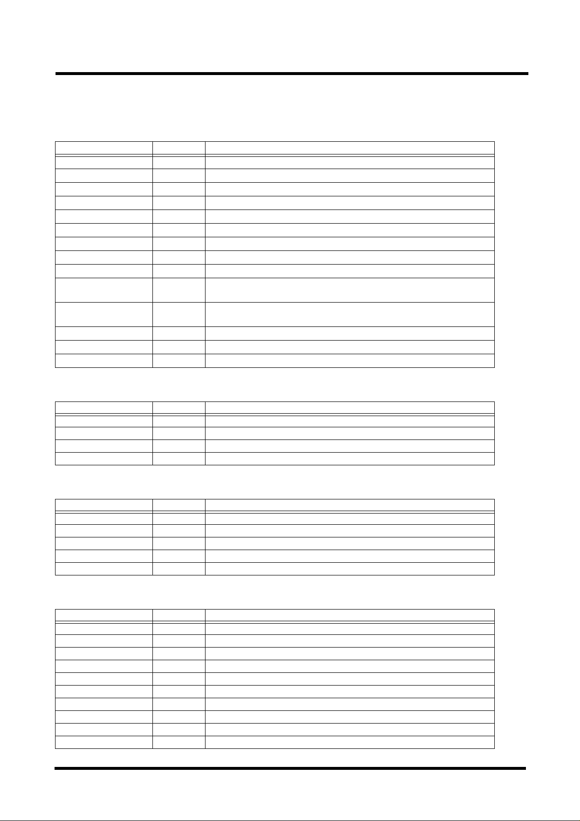
REVISION STATUS
From serial No.
Revision no. of
document
Page Revision no. of page
0-1 0111111
0-2 0111111
1-1 0111111
1-2 0000000
2-1 0122333
2-2 0111222
2-3 0122222
2-4 0122222
2-5 0111121
2-6 0122222
2-7 0111112
2-8 0122222
2-9 0122222
2-10 0000000
1006
1021
1056
1096
1221
1426
4001
012345678910111213141516171819
3-1 0122222
3-2 0123333
3-3 0122333
3-4 0122333
3-5 0111111
3-6 0122333
3-7 0122333
3-8 0122222
3-9 0122222
3-10 0122222
3-11 0122223
3-12 0111111
3-13 0122333
3-14 0111111
3-15 0112222
3-16 0000000
Siemens-Elema SRX-U RX B7-120.051.01.0 8.02 MAMMOMAT 300
Solna, Sweden REV.06 12.95 63 85 772

REVISION STATUS
X041E
From serial No.
Revision no. of
document
Page Revision no. of page
4-1 0122222
4-2 0122223
4-3 0111111
4-4 0122223
4-5 0122233
4-6 0111111
4-7 0122222
4-8 0122222
4-9 0111111
4-10 0122222
4-11 0122222
4-12 0122222
4-13 0122222
4-14 0111111
1006
1021
1056
1096
1221
1426
4001
012345678910111213141516171819
5-1 0122223
5-2 0122222
5-3 0122223
5-4 0122222
5-5 0122222
5-6 0122223
5-7 0122222
5-8 0122223
5-9 0122222
5-10 0123333
6-1 0111111
6-2 0122222
7-1 0123455
7-2 0123455
Siemens-Elema SRX-U RX B7-120.051.01.0 8.02 MAMMOMAT 300
Solna, Sweden REV.06 12.95 63 85 772

X041E 0-1
TABLE OF CONTENTS
1 System Overview..................................................1-1
2 Stand Overvie w................. ... .. ................. .. ... ......... 2-1
Placement of PC-boards and Components, Stand ...........................2-1
List of Boards and Fuses, Stand.......................................................2-2
List of Switches and Components, Stand..........................................2-3
List of Signals and Testpoints, Stand ................................................2-4
List of Voltages and Testpoints, Stand ..............................................2-8
3 Stand Functional Diagrams...................................3-1
Block Diagram Cable Connections....................................................3-1
Grounding Connections ....................................................................3-2
Mains Connection, Power Supply CPU.............................................3-3
Power Supply Motor Control .............................................................3-4
Display ..............................................................................................3-5
CPU Board Internal, Generator Interface..........................................3-6
Tube, Temperature Monitoring..........................................................3-7
Lift and Rotation Motor Drive.............................................................3-8
Lift and Rotation Switches.................................................................3-9
Compression Measurement Signals ...............................................3-10
Compression Motor Drive................................................................3-11
Tube Angle Measurement, Pot. Return...........................................3-12
Collimator........................................................................................3-13
Object Table ....................................................... ....... ...... ................3-14
Automatic Exposure Control (AEC).................................................3-15
4 Generator Overview..............................................4-1
Mains Voltage Connection ................................................................4-1
List of PC-Boards and Components, Generator................................4-2
List of Fuses, Generator....................................................................4-3
Placement of PC-Boards and Components, Generator....................4-4
Control Panel Functions....................................................................4-5
List of Switches and Components, Generator...................................4-6
List of Signals and Testpoints, Generator..........................................4-8
Signal Diagram ...............................................................................4-14
Siemens-Elema SRX-U RX B7-120.051.01.0 8.02 MAMMOMAT 300
Solna, Sweden REV.01 12.95 63 85 772

0-2 X041E
TABLE OF CONTENTS
5 Generator Functional Diagrams............................5-1
Block Diagram. ...... ...... .............................................. ...... ....... ........... 5-1
Ground, 0V and Protection Ground Distribution................................5-2
Line Input ..........................................................................................5-3
Back Plane D700 ..............................................................................5-4
Principle Diagram, Master.................................................................5-5
Principle Diagram, Tube Filament.....................................................5-6
Principle Diagram, Inverter Control and KV Regulation....................5-7
Principle Diagram, Inverter................................................................5-8
Principle Diagram, Control Panel......................................................5-9
Principle Diagram, Iontomat............................................................5-10
6 Generator PC Board Overview.............................6-1
7 Compatibility List................................................... 7-1
Siemens-Elema SRX-U RX B7-120.051.01.0 8.02 MAMMOMAT 300
Solna, Sweden REV.01 12.95 63 85 772
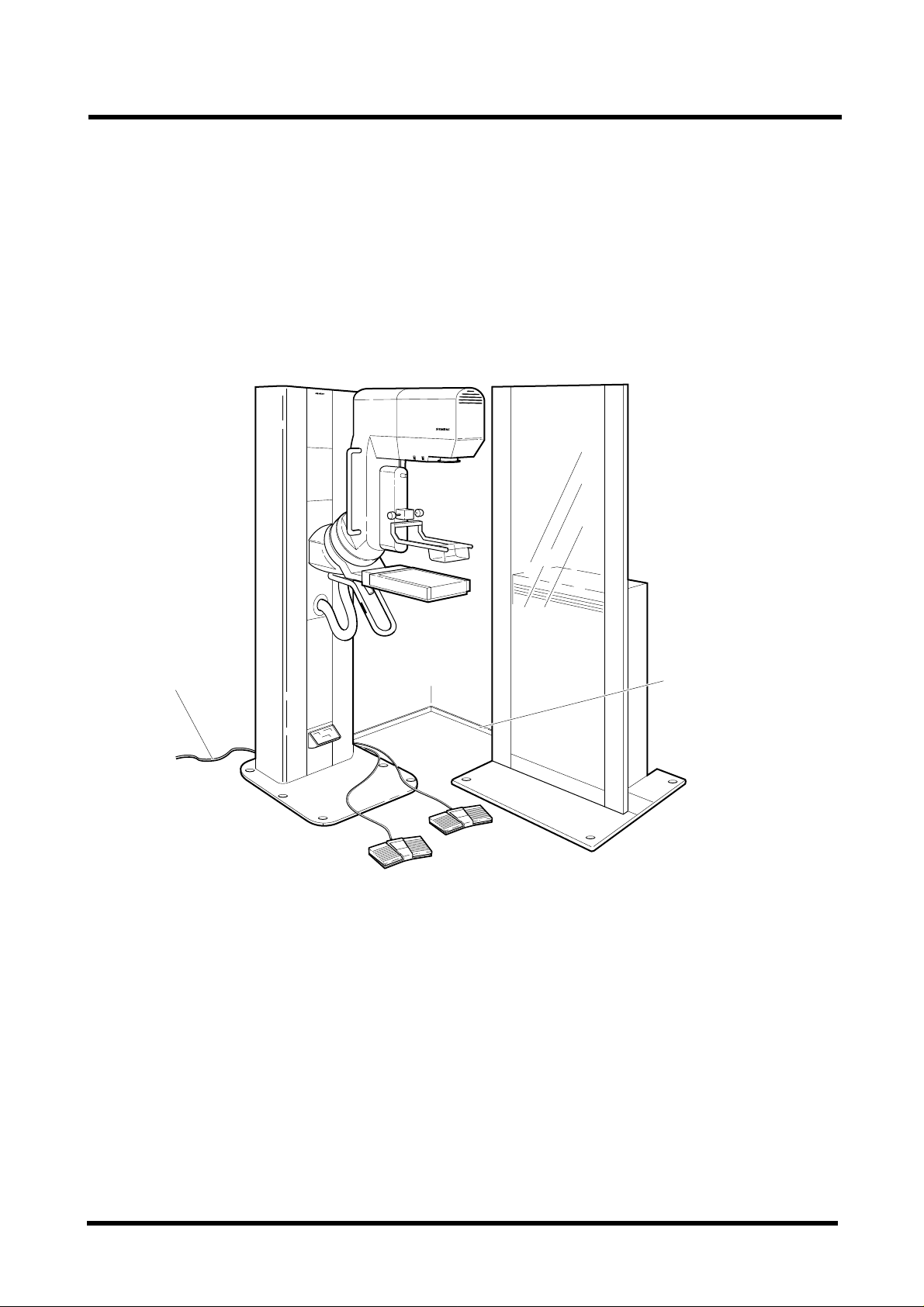
X041E 1-1
SYSTEM OVERVIEW
Cable ductCable duct
STAND GENERATOR
9555 0001
Siemens-Elema SRX-U RX B7-120.051.01.0 8.02 MAMMOMAT 300
Solna, Sweden REV.01 12.95 63 85 772

1-2 X041E
Siemens-Elema SRX-U RX B7-120.051.01.0 8.02 MAMMOMAT 300
Solna, Sweden REV.00 12.95 63 85 772
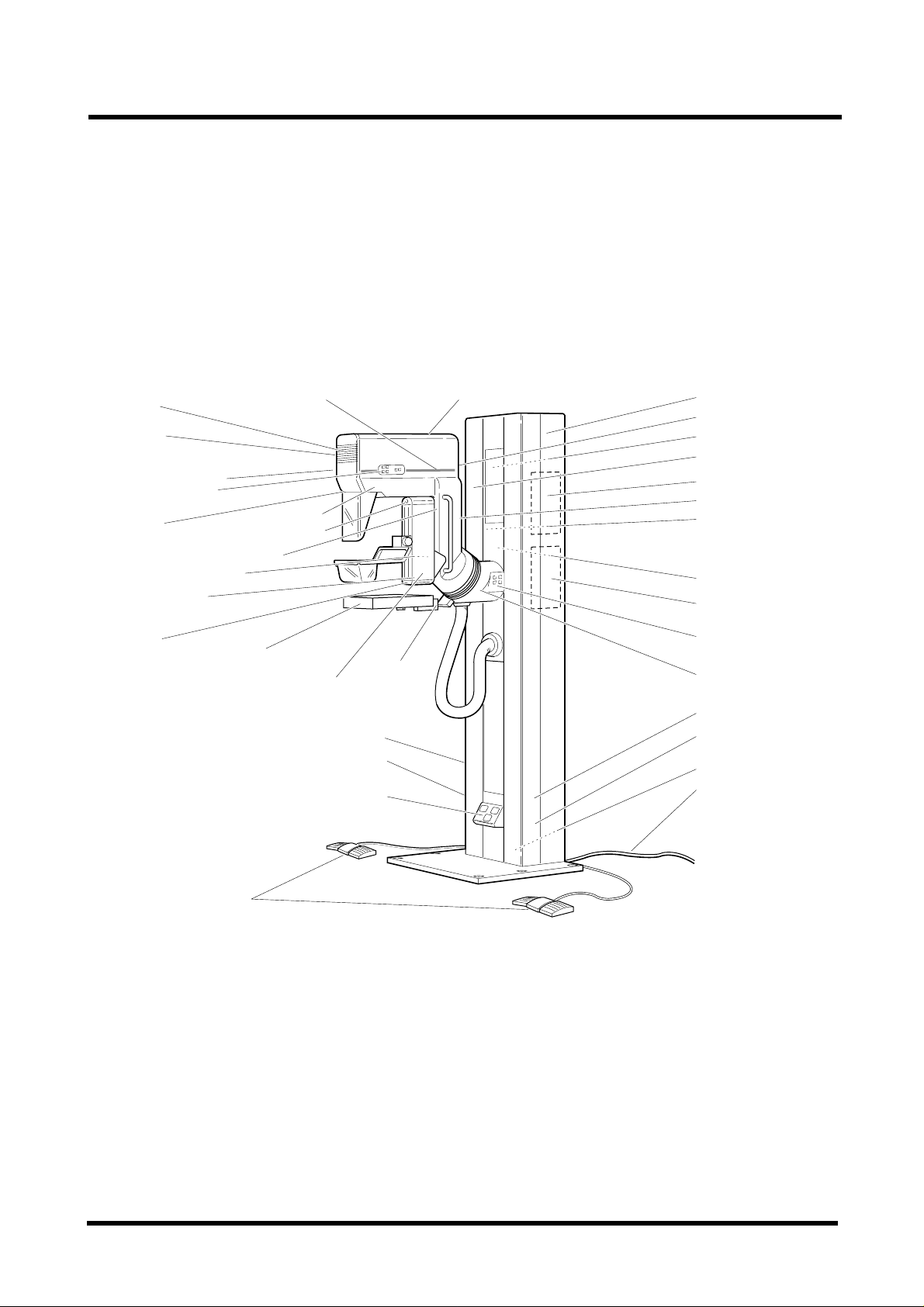
X041E 2-1
PLACEMENT OF PC-BOARDS AND COMPONENTS, STAND
Tube
K7-K9
D807 Rigth side
D807 Left side
Lamp
M2 (Compression)
Strain gauge
D804
R861
X874
Object table
S1
S2
M
S897
R863
S883
S884
D803
S892
X892
M6 (Fan)D805
M1 (Lift)
R871
S882
S881
D801
S880
D806
With
Photo transistor
M3 (Rotation)
D802
D808 Right side
D808 Left side
D803
X880
X899
T801
Incoming mains
Fooy pedals
9555500
Siemens-Elema SRX-U RX B7-120.051.01.0 8.02 MAMMOMAT 300
Solna, Sweden REV.03 12.95 63 85 772

2-2 X041E
LIST OF BOARDS AND FUSES, STAND
PCB OVERVIEW
D801 CPU BOARD
D802 MOTOR CONTROL BOARD
D803 DISPLAY BOARD
D804 FORCE AMPLIFIER BOARD
D805 WING BOARD
D806 ANGLE DETECTOR BOARD
D807 BOARD FOR LIFT, ROTATION AND LAMP SWITCHES
D808 BOARD FOR LIFT AND ROTATION SWITCHES
FUSES OVERVIEW
PCB FUSE FUSED VOLTAGE
D801 F1 2 AT +5V, +5V_REF, +5V_DSP, +7V
D801 F2 1 AT +5V_DUEP
D802 F1 5 AT +5V, +5V_M, +14V, D805/+5V
D802 F2 3.15 AT +24VF, +15V
D802 F3 6.3 AT +24V
D802 F4 4 AT 16VAC (LAMP)
D802
Chassis-mounted
fuses
NOTE! See spare parts list for replacement fuses.
F5 1 AT
F801 2 AT
F802 1 AT 11 V_DP
F803 5 AT 14 VAC
F804 5 AT 16 VAC
F805 6.3 AT 24 VAC
24VACF (FAN)
11 VAC
Siemens-Elema SRX-U RX B7-120.051.01.0 8.02 MAMMOMAT 300
Solna, Sweden REV.02 12.95 63 85 772
X041E 2-3
LIST OF SWITCHES AND COMPONENTS, STAND
SWITCHES
Switch Page Description
S2/Object table 3-14/2A Cassette inserted switch.
S1/D801 3-6/1D Reset switch for stand CPU.
S1/Object table 3-14/2A Grid out switch located in the object table.
S1-S6/D807 3-8/2A Control switches for lamp, lift- and rotation movement. Left and right side.
S1-S4/D808 3-8/4B Control switches for lift- and rotation movement. Left and right side.
S861 3-11/2G Compression limit switch, compression unit.
S862 3-11/2G Decompression limit switch, compression unit.
S880 3-4/2B Emergency stop, switches off 24VAC and 14VAC, machine blocked.
S881 3-8/2G Lift up limit switch, rotating unit.
S882 3-4/2A Limit switch, distance tube head - floor <50 mm, switches off 24VAC,
machine blocked.
S883 3-8/4B Collision protection switch, risk for collision when tubehead is less than
120 mm from the floor.
S884 3-8/2G Down limit switch, rotating unit.
S892 3-14/2C Object table locked in position.
S897 3-13/2D Diaphragm switch.
POTENTIOMETERS
Potentiometer Page Description
R803 3-12/2A Tube angle, 2k.
R861 3-10/3E Preset force, 10k.
R863 3-10/3E Thickness, 2k.
R871 3-12/2A Preset angle, 10k.
MOTORS
Motor Page Description
M1 3-8/2G Lift motor.
M2 3-11/2G Compression motor.
M3 3-8/3G Rotation motor.
M6 3-7/4E Fan, tube cooling.
M 3-14/2A Grid motor
MISCELLANEOUS
Misc. Page Description
T801 3-3/2C Mains transformer.
LAMP 3-13/3G Object illumination.
R801 3-13/5F Lamp resistor.
R807 3-8/2G Lift motor varistor.
COMP. UNIT 3-10/2C Compression unit.
CABLE DUCT 3-2/3A Generator to stand cable protection
GROUND RAIL 3-2/1E System grounding terminal
K7 3-7/4E Fan thermostat
K8 3-7/4E Tube temperature above normal
K9 3-7/4E Tube temperature too high
Siemens-Elema SRX-U RX B7-120.051.01.0 8.02 MAMMOMAT 300
Solna, Sweden REV.03 12.95 63 85 772
2-4 X041E
LIST OF SIGNALS AND TESTPOINTS, STAND
Misc. Page Description
L801 - L809 3-8, 3-11 UHF chokes (EMC)
Page Signal Name Origin Via Destination Testpoint LED
3-14/2E AEC_POS D805 D801
3-6/2B AR D801 GENERATOR D801 AR
3-10/3B BR_OPEN D804 D804.X843 pin 8 V2
3-10/3B BR_RET D804 D804.X843 Pin 7
3-14/1A CASS_LOADED OBJ. TABLE D805 D801
3-11/1B
3-10/2F COMP_FORCE D804 D801 D804.X843 pin 5
3-11/1E COMP D802 D805 COMP. UNIT
3-11/3E COMP_OK D802 D801 D802 V2
3-11/1E COMP_PROT D802 D801 D802
3-11/1B
3-11/2D C_PWM D802 D802
3-11/4F COMPRESS PEDAL D805 D801, D802
3-11/1E DECOMP D802 D805 COMP. UNIT
3-11/4F DECOMPRESS PEDAL D801
3-8/2C
3-8/4F DRIVE_OK D802 D801 D802 V12
3-8/1E DRIVE_PROT D802 D801 D802
3-14/3B GRID_MOTOR_N D802 D805 OBJ. TABLE
3-14/2A GRID_OUT OBJ. TABLE D805 D801 D801 GRID_O
3-14/2G
3-10/3D I1_OUT D804 D804.X843 pin 6
3-6/2B
3-13/3G LAMP D807 D805 D801
3-13/4D
3-9/3A LIFT_DOWN D807, D808 D805 D801, D802
3-9/3A LIFT_UP D807, D808 D805 D801, D802
3-8/2E L_PWM D802 D802
3-6/3B MPS D801 GENERATOR D801
3-7/4C OKT1_ TUBE/K8 GENERATOR
3-7/4C OKT2_ TUBE/K9 GENERATOR
COMP_DIR D801 D802 D802 COMP_D
*
COMP_SPEED D801 D802 D801, D802
*
DIR D801 D802 D802
*
GRID_SPEED D801 D802 D801 GRID_SP
*
KVA D801 D700
*
LAMP_CTRL D801 D802
*
(GENERATOR)
COMP_SP
D801
COMP_ERR
DRIVE_ERR
“*SIGNAL” = “SIGNAL” active low
Siemens-Elema SRX-U RX B7-120.051.01.0 8.02 MAMMOMAT 300
Solna, Sweden REV.02 12.95 63 85 772

X041E 2-5
LIST OF SIGNALS AND TESTPOINTS, STAND
Signal Name Description
AEC_POS AEC-detector in position near breast. Not used in M300.
AR Signal given to generator as exposure request. If grid used, grid has started.
BR_OPEN Bridge open, strain gauge for compression force not working correctly.
BR_RET Compression force strain guage return line (appr. 0V)
CASS_LOADED Cassette inserted in object table.
COMP_DIR Controls compression motor to compress (moving down)
*
COMP_FORCE Analog signal indicating compression force.
COMP Power output via compression limit switch to compression motor.
COMP_OK Compression motor working correctly, no over current.
COMP_PROT Compression relay K1 is working correctly, checked 1s after pedal release.
COMP_SPEED Pulse Width Modulated signal to control speed of compression motor.
*
C_PWM Pulse Width Modulated power output to compression motor.
COMPRESS Operator control signal to move compression plate down.
DECOMP Power output via decompression limit switch to compression motor.
DECOMPRESS Operator control signal to move compression plate up.
DIR Selecting direction of rotation or lift motor.
*
DRIVE_OK Rotation and lift motor are working correctly, no over current.
DRIVE_PROT DMG relay K3 is working correctly, checked 3s after rot/lift botton is released.
GRID_MOTOR_N Grid motor return line.
GRID_OUT Active when the grid is not in stand by position.
GRID_SPEED Pulse Width Modulated signal control speed of grid motor.
*
I1_OUT Output signal from compression force preamplifier.
KVA Signal to terminate exposure.
*
LAMP Operator control signal to the field lamp.
LAMP_CTRL Signal to switch object illumination on.
*
LIFT_DOWN Operator control signal to move compre ssion plate down.
LIFT_UP Operator control signal to m ove compress ion plate up.
L_PWM Pulse Width Modulated power output to rotation or lift motor.
MPS Multi processor serial communication for information exchange Master - Slaves.
OKT1_ Signal from temperature switch K8 on the tube.
OKT2_ Signal from the over pressure switch K9 on the tube.
Siemens-Elema SRX-U RX B7-120.051.01.0 8.02 MAMMOMAT 300
Solna, Sweden REV.01 12.95 63 85 772

2-6 X041E
LIST OF SIGNALS AND TESTPOINTS, STAND
Page Signal Name Origin Via Destination T es tpoin t LED
3-12/2D POT_RETURN POT D801
3-10/2E PRES_FORCE R861 D801
3-12/1A PRESET_ANGLE R871 D805 D801
3-11/2D PU D802 D802
3-6/1E
3-6/1E
3-6/1E RESET_SW D801
3-9/3A ROT_CW D807, D808 D 80 5 D802
3-9/3A ROT_CCW D807, D808 D805 D802
3-12/4A ROT_POS D806 D801
3-6/3D RXD GEN. D801 D801
3-8/3C
3-8/2C
3-13/4A STEREO_COLL S897 D801
3-14/1B TABLE_ C ONF IG OBJ.TABLE D805 D801
3-10/3E THICKNESS R863 D801
3-12/2A TUBE_ANGLE R803 D 801
3-6/4D TXD D801 GENERATOR D801 TXD
3-6/3B VH GEN. D801
3-10/3C ZERO D804 D804.X843 pin 4
RESET D801
*
RESET_HW D801
*
SEL_ROT D801 D802 D802 SEL_ROT
*
SPEED D801 D802 D801, D802 SPEED
*
“*SIGNAL” = “SIGNAL” active low
Siemens-Elema SRX-U RX B7-120.051.01.0 8.02 MAMMOMAT 300
Solna, Sweden REV.02 12.95 63 85 772
X041E 2-7
LIST OF SIGNALS AND TESTPOINTS, STAND
Signal Name Description
POT_RETURN Return line potentiometers connected to 0VA via a resistor.
PRES_FORCE Analog signal as preset value for maximum compression force.
PRESET_ANGLE Analog signal as preset value for requested rotation angle.
PU Pull up signal for error comparators = +15V, +5V, +24V voltages OK.
RESET Reset signal to the CPU.
*
RESET_HW Reset signal from the CPU to the reset circuit, used for slave restart and CPU watchdog
*
RESET-SW Signal from the reset switch to the CPU via the reset circuit.
*
ROT_CW Operator control signal to rotate the x-ray system clockwise.
ROT_CCW Operator control signal to rotate the x-ray system counter clockwise.
ROT_POS Low level signal pulse indicating +10 or -10 degrees of rotation.
RXD Input for receiving data via MPS.
SEL_ROT Low level signal selects the rotation drive to be controlled.
*
SPEED Pulse Width Modulated signal to control speed of rotation or lift motor.
*
STEREO_COLL Diaphragm switch, diaphragm in place. For 18 x 24 or spot diaphragm.
TABLECONFIG Inputs from object table, see configuration table.
THICKNESS Analog signal indicating the compression thickness.
TUBE ANGLE Analog signal indicating the rotation angle.
TXD Output for sending data via MPS.
VH The stand is informed that the generator has completed its preparation.
ZERO Used for adjusting offset of the compression force amplifiers.
reset.
Siemens-Elema SRX-U RX B7-120.051.01.0 8.02 MAMMOMAT 300
Solna, Sweden REV.01 12.95 63 85 772
2-8 X041E
LIST OF VOLTAGES AND TESTPOINTS, STAND
Page Voltage Origin Supplied
from
3-3/4E +5V D80 1 11V Digital IC,
3-3/4E
3-10/3B
3-3/3E +5V_DSP D801 11V D803, Display 5V_DSP V6 D801/F1
3-3/2E
3-10/3B
3-3/3E +5V_DP D801 11V_DP Generator
3-3/3D 0VD GND D801/X811 Digital IC 0VD1, 0VD2
3-3/3D
3-10/3B
3-6/5D 0V_DP D700/GND Generator inter-
3-3/2C 11V T801 230VAC +5V, +5V_DSP,
3-6/5B 11V_DP T801 230VAC +5VDP D801/F2
3-4/3D +5V D802 14VAC Digital IC 5V V7 D802/F1
3-4/4E +5V_M D802 +5V D801-D802
3-4/3D +14V D802 14VAC +5V, D805/+5V 14V D802/F1
3-4/2D +15V D802 +24V Transistor
3-4/2C +24V D802 24VAC +15V, +24VF D802/F3
3-4/2D +24VF D802 +24V Switches,
3-4/3A 14VAC T801 230VAC +14V D802/F1
3-13/5E 16VAC T801 230VAC LAMP D802/F4
3-4/2A 24VAC T801 230VAC D802/F3
3-4/2E 24VACF D802 24VAC Fan D802/F5
3-4/3B 0V GND D802/X821 Ground 0V, OV1
3-4/2F +5V D805 D802/+14V Digital IC 5V V17 D802/F1
3-4/2G +5V_R D805 +5V User switches D802/F1
3-4/3D +14V D802 +24V Switches,relays D802/24VF D802/F2
3-4/2D +24VF D802 +24V Switches,relays D802/24VF D802/F2
3-3/2B 230VAC Generator D701/X14 Stand X881/2,3
3-3/1C P.E. Stand X899 Inc. mains voltage Whole system X899/PE
3-3/1C N Stand X 899 Inc. mains voltage Whole system X899/N
3-3/1C L1 Stand X899 Inc. mains voltage Whole system X899/L1
3-3/1C L2 Stand X899 Inc. mains voltage Whole system X899/L2
3-3/1C L3 Stand X899 X899/L3
+5V_REF D801 +5V Pots.
+7V D801 11V Analog IC,
0VA 0VD D801 Analog IC
Supply for Testpoint LED Fuse
5V V7 D801/F1
+5V_REF
D804
D804
interface
D804
face ground
+7V
upto interface
drivers
relays
5V_REF
X843 pin 2
7V
X843 pin1
5V_DP V8 D801/F2
0V A1, 0VA 2
X843 pin 3
0V_DP
15V V49 D802/F2
24VF D802/F2
V5 D801/F1
V7 D802/F1
D801/F1
D801/F1
Siemens-Elema SRX-U RX B7-120.051.01.0 8.02 MAMMOMAT 300
Solna, Sweden REV.02 12.95 63 85 772
X041E 2-9
LIST OF VOLTAGES AND TESTPOINTS, STAND
Voltage Description ( typical value)
+5V Regulated DC voltage, 4.75V < +5V < 5.25V
+5V_REF Regulated DC voltage, +5V -5% < +5V_REF < +5V
+5V_DSP Regulated DC voltage, 4.75V < +5V_DSP < 5.25V
+7V Regulated DC voltage, 6.60V<+7V<7.25V
+5V_DP Regulated DC voltage, 4.75V < +5V_DP < 5.25V
0VD Digital ground
0VA Analog ground
0V_DP Generator interface ground. Floating, grounded by generator.
11V AC supply voltage, 11VAC
11V_DP AC supply voltage, 11VAC
1)
1)
+5V Regulated DC voltage, 4.75V < +5V < 5.25V
+5V_M Regulated DC voltage, 4.75V < +5V_M < 5.25V
+14V Unregulated DC voltage, 18V
1)
+15V Regulated DC voltage, 14.25V < +15V < 15.75V
+24V Unregulated DC voltage, 32V
+24VF Unregulated DC voltage, 32V
14VAC AC supply voltage, 14 VAC
16VAC AC supply voltage, 16 VAC
24VAC AC supply voltage, 24VAC
1)
1)
1)
1)
1)
24VACF AC supply voltage for the fan
0V Circuit ground
+5V Regulated DC voltage, 4.75V < +5V < 5.25V
+5V_R Regulated DC voltage, 4.40V < +5V_R < 5.25V
+14V Unregulated DC voltage, 18V
+24VF Unregulated DC voltage, 32V
1)
1)
230VAC Stand mains voltage input, 195VAC < 230VAC < 253VAC
P.E. Protective earth terminal, incoming mains
N Neutral line terminal, incoming mains
L1 Line 1 terminal, incoming mains vo ltage
L2 Line 2 terminal, incoming mains vo ltage
L3 Not used
1)
STANDBY TYPICAL VALUE, 230VAC INPUT
Siemens-Elema SRX-U RX B7-120.051.01.0 8.02 MAMMOMAT 300
Solna, Sweden REV.03 12.95 63 85 772

2-10 X041E
Siemens-Elema SRX-U RX B7-120.051.01.0 8.02 MAMMOMAT 300
Solna, Sweden REV.00 12.95 63 85 772
X041E 3-1
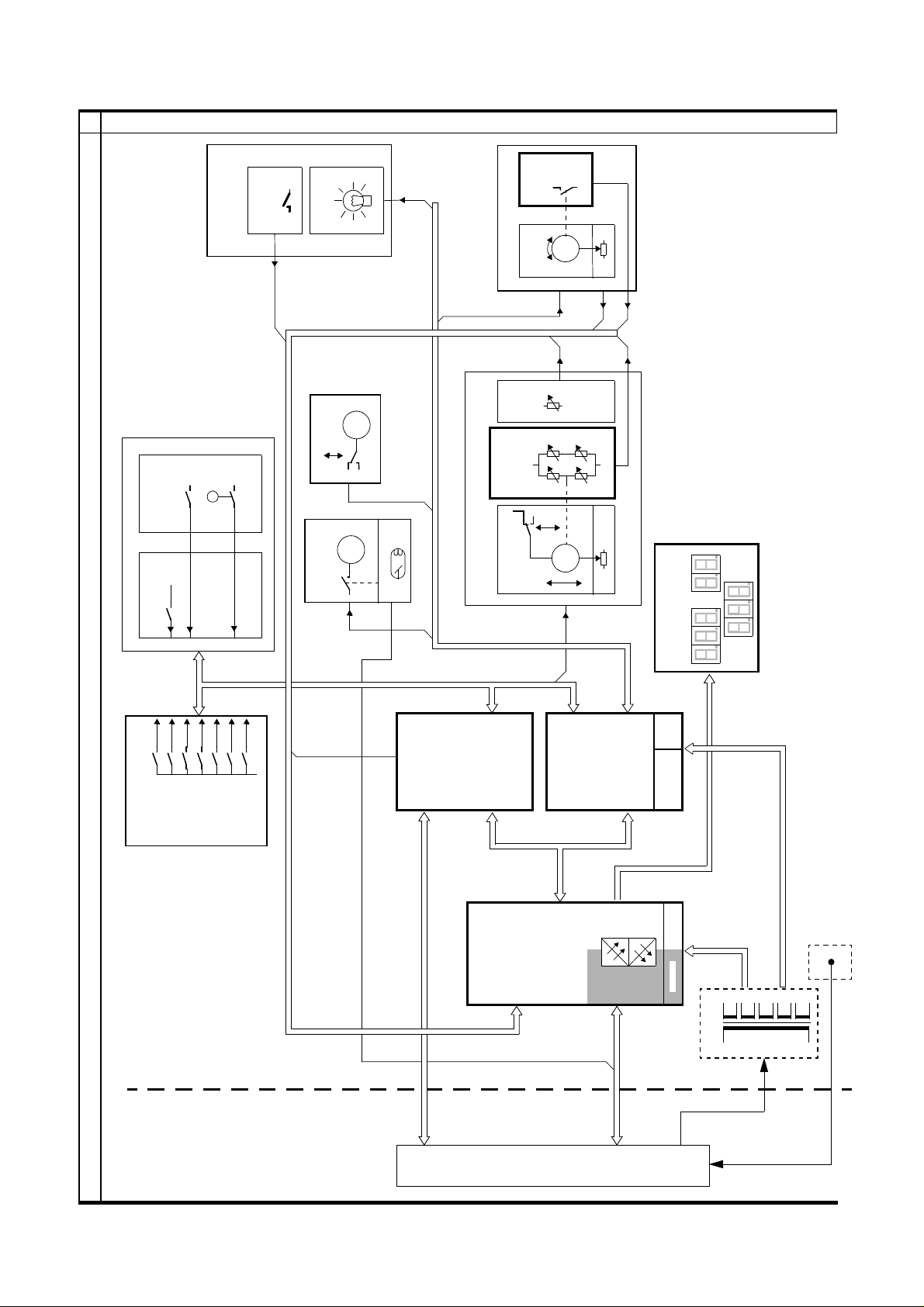
BLOCK DIAGRAM CABLE CONNECTIONS
123
4
5
OBJECT TABLE
TABLE BASE OBJECT TABLE
LAMP
X894
COLLIMA TOR
X894
D806
ANGLE
DETECTOR
ROTATION
ROTATION
X888
X874
PRESET
FORCE
X841 X861
M
D804
COMPRESSION
CASS IN PLACE
M
GRID OUT
GRID
X887
M
FAN LIFT
T. IN POS
TUBE TEMP
X895
X895
COMPRESSION
FORCE
F
MM
COMPRESSION
USER INTERFACE
STAND
X826-X829
COMP
DECOMP
X892
X844-X849
X880
ROT CW
ROT CCW
LIFT UP
LIFT DOWN
D803
DISPLAY
X801
X851
X889
X865
X869
X871
X863
X865
X868
+24V
D805
WING BOARD
X855
X856
X858
LAMP
X870
X860
D801
80C535
CPU BOARD
X824
D802
X812
X813
X814
X813
X814
X823
X824
X821
16V AC
+24V +15V
+7V +5V
+5V_DP
+14V +5V
INCOMING MAINS
110, 208, 230, 240, 277 OR 400V
X811
X886
X886
SINGLE OR TWO PHASE
X899
MOTOR CONTROL
X822
X823
X816
T801
230V FROM GENERATOR
X886
ABCDEFG
GENERATOR
Siemens-Elema
SRX-U RX B7-120.051.01.08.02
Solna, Sweden
REV.
02
X10
.
GEN
X11
X1 X815
MAMMOMAT 300
12.95
63 85 772
3-2 X041E
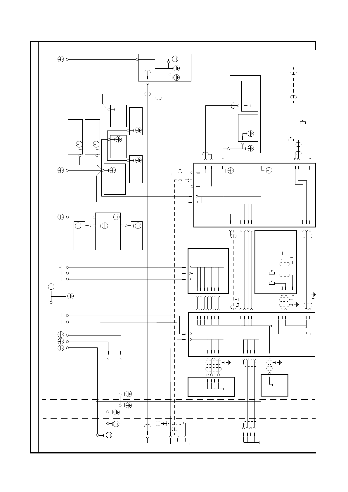
GROUNDING CONNECTIONS
123
FRONT
COVER
TUBE
REAR
H3
X896
COVER
X897
HOUSING
4
5
STAND
BELLOWS RING
GROUND RAIL
CURTAIN
BELLOWS RING
UPPER
LIFT
CARRIAGE
TUBE
TUBE
COMPRESSION
UNIT
PLATE
CHASSIS
PATIENT
HANDLE
PATIENT
HANDLE
LOWER
X884
DETECTOR
4
0V_RDL
FILAMENT
ROTATION
OBJEKT
BOARD
9
WING 2
X892
16
X869
14
BOARD
X871
SHLD_1
252729
12
X855
0V
30
X856
COMPRESSION
6
5
58
2
X821
4
X870 6
X860
D805
WING
D802
MOTOR
BOARD
1234568
X822
NOTE
DOTTED CONNECTIONS INDICATE
SHEILDED CABLES WITHOUT
0V CONNECTION
10k
R871
PRESET_ANGLE
R803
2k
TUBE_ANGLE
X86856
X863
X855
1
SHLD
4
5
3
POT_RET
X859
0V
0V A
2
X841
D804
COMPRESSION
FORCE
THICK-
NESS
2k
R863
726
10k
X874
UNIT
PRES_FORCE
R861
INCOMING MAINS
X899
P.E.
1
2
33
34
X813
1
137
8
X815
141615
X814
0V
0V_DUEP
36
X813
9
17
20
0V A
X880
1234568
X812
4
3
X811
1
4
X881
D801
CPU
X816
151617
0V D
18
STAND
4
X861
D806
0V
ANGLE
DETECTOR
151617
18
X801
D803
FOR FOOTPEDALS
CABLE
CABLE
DUCT
DISPLAY
0V D
ABCDEFG
GENERATOR
Siemens-Elema
Solna, Sweden
X9
X8
X11
A
J
P
H
0V_RDL
SRX-U RX B7-120.051.01.08.02
REV.
03
12.95
X1
136
11
GND
MAMMOMAT 300
63 85 772
 Loading...