

Page 1

MAMMOMAT 1000/3000
Service
Service Program
SP
© Siemens AG 1999
The reproduction, transmission or
use of this document or its contents
is not permitted without express
written authority. Offenders will be
liable for damages. All rights,
including rights created by patent
grant or registration of a utility
model _or_ design,_are_ reserved.
Register 5 English
Print No.: SPB7-230.114.02.01.02 Doc . Gen. Date: 03.99
Replaces: n.a.
65 19 792
Page 2

0 - 2 Revision
Chapter Revision
All 01
Mammomat 1000/3000 Register 5 SPB7-230.114.02 Page 2 of 4 Siemens-Elema AB
Service Program Rev. 01 03.99 SPS-UD Solna, Sweden
Page 3

Contents 0 - 1
Page
This document is valid from serial No. 6500 and from FW-version 3.0.
1 _______Working with the service PC _____________________________________1 - 1
Description of the syntax used in these instructions . . . . . . . . . . . . . . . . . . 1 - 1
Connecting the service PC . . . . . . . . . . . . . . . . . . . . . . . . . . . . . . . 1 - 2
2 _______Adjustment and service PC programs _____________________________2 - 1
Configuration . . . . . . . . . . . . . . . . . . . . . . . . . . . . . . . . . . . . . . 2 - 1
Service . . . . . . . . . . . . . . . . . . . . . . . . . . . . . . . . . . . . . . . . 2 - 37
Normal mode . . . . . . . . . . . . . . . . . . . . . . . . . . . . . . . . . . . . . 2 - 47
Te st DUEP communication . . . . . . . . . . . . . . . . . . . . . . . . . . . . . . 2 - 55
Backup . . . . . . . . . . . . . . . . . . . . . . . . . . . . . . . . . . . . . . . . 2 - 56
3 _______Error messages________________________________________________3 - 1
General . . . . . . . . . . . . . . . . . . . . . . . . . . . . . . . . . . . . . . . . .3 - 1
Error messages of the master Er 0XX. . . . . . . . . . . . . . . . . . . . . . . . . . 3 - 2
Error messages of the control deck Er 3XX. . . . . . . . . . . . . . . . . . . . . . . 3 - 7
Error messages of the IONTOMAT PM Er 5XX . . . . . . . . . . . . . . . . . . . . .3 - 8
Error messages of the power pack Er 6XX . . . . . . . . . . . . . . . . . . . . . . 3 - 11
Error messages of the stand Er 8XX . . . . . . . . . . . . . . . . . . . . . . . . . 3 - 15
Siemens-Elema AB Register 5 SPB7-230.114.02 Page 1 of 2 Mammomat 1000/3000
Solna, Sweden Rev. 01 03.99 SPS-UD Service Program
Page 4

0 - 2 Contents
Page
This page intentionally left blank.
Mammomat 1000/3000 Register 5 SPB7-230.114.02 Page 2 of 2 Siemens-Elema AB
Service Program Rev. 01 03.99 SPS-UD Solna, Sweden
Page 5

Working with the service PC 1
Description of the syntax used in these instructions 1
< ..... > The indication of which function keys to press is given between
these characters, for example <ENTER>, <ESC> etc.
CAPITALS Capital letters indicate data which must be entered unchanged,
for example the name of a register, files etc.
1 - 1
Italics
[ ..... ] Square brackets enclose additions to commands which may be
Bold Data relating to formats, user entries etc., which is important for
xx yy zz Data can be entered in place of
{...} Curved brackets indicate that out of several terms listed one be-
NOTICE
* * * * * When the password is entered, only these characters are shown.
Menu Selection: When several menus, programs, fi les etc. are presented f or selec-
Italics represent data in whi ch a value should be ent ered, e. g. for
user name, the name of the technician should be entered.
optionally entered.
the following entry, is shown in bold as it appears on the monitor
screen.
This character indicates that at this point the space key must be
pressed.
"x, y, z"
(e.g. day´s date).
low the other, one must be selected.
Important remarks are indicated with this box.
tion, they are shown in a box (program window).
Selection is made with the <↓> and <↑> keys.
The module selected is highligthed in the display.
<ENTER> Every entry must be confirmed with the <ENTER> key.
<ESC> ESC allows paging back through the program.
<xx> + <y> Some functions are selected by pressing two keys
simultaneously. Procedure: Press, for example, the <Shift> key
and keep it depressed, press the <*> key and then release both
keys.
<F1> Key <F1> calls up a selective help text.
<F10> Key <F10> exits the program.
Siemens-Elema AB Register 5 SPB7-230.114.02 Page 1 of 6 Mammomat 1000/3000
Solna, Sweden Rev. 01 03.99 SPS-UD Service Program
Page 6

1 - 2 Working with the service PC
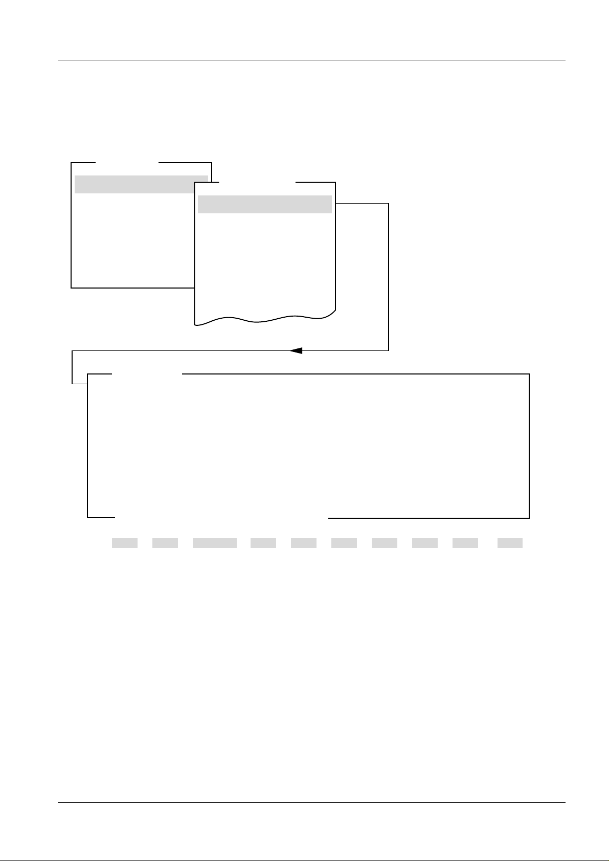
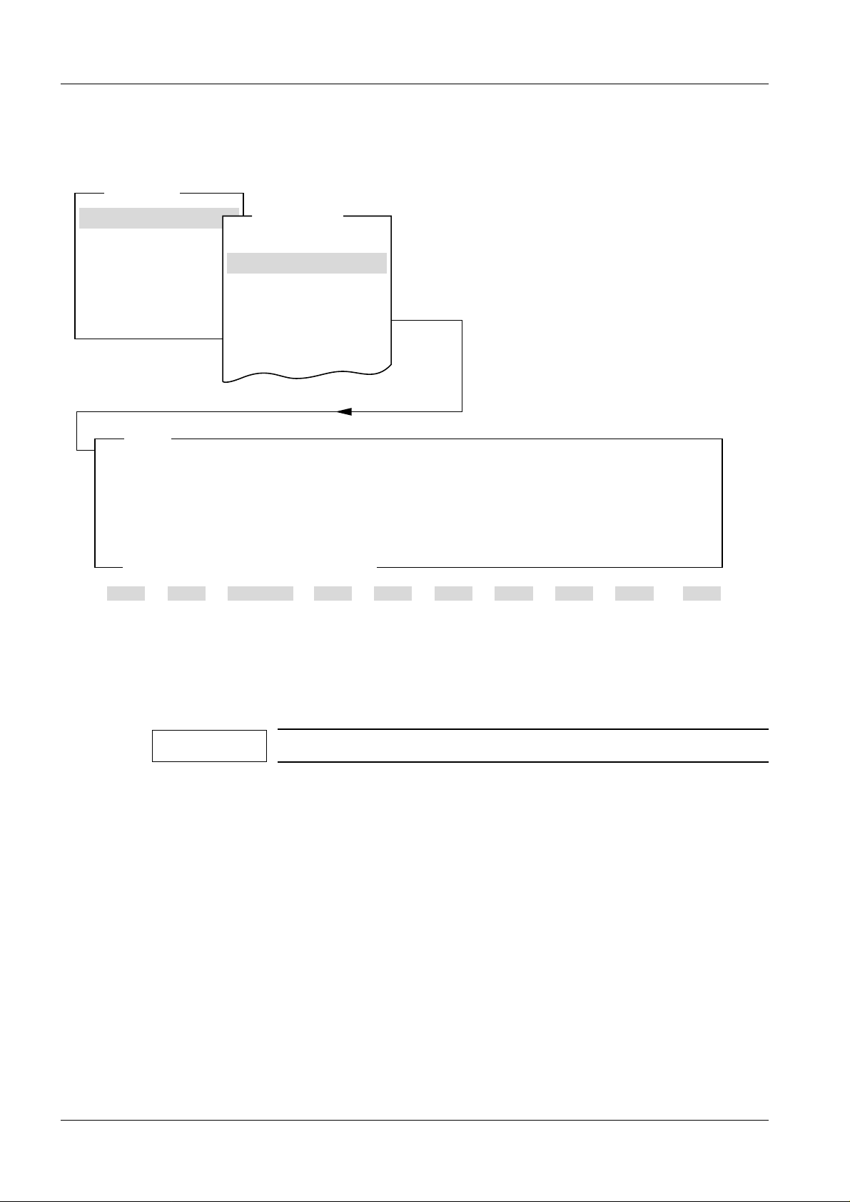
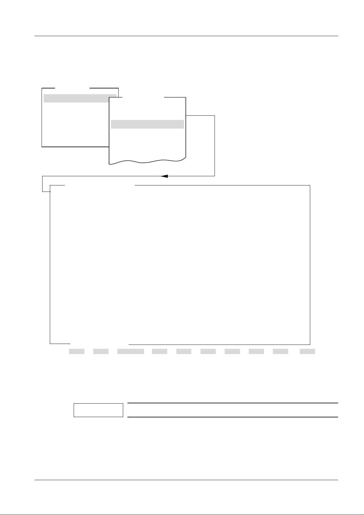
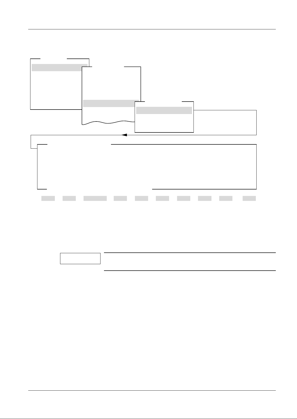
XXX - - XXX - XXX - - XXX
By this means, the way is shown how to call up a particular subroutine (display windows).
For example:
Main menu –
Configuration –
Iontomat –
Corr . curve –
Connecting the service PC
The service PC must be connected with connecti ng cable part no. 99 00 440 RE999 to p.c.
board in the generator (do not i nsert the diskette in the drive yet). Use port COM 1 on the
service PC.
Starting up and using the service PC
1. Switch on generator and service PC.
After initialization, the s ervice PC shows: C:\>
2. Now insert the discette with th e service program.
3. Select the appropriate drive and then press <ENTER>. The screen shows:
A:\> or B:\>
{A:}
{B:}
4. Start the service program by typing ’SERVICE’, then press <ENTER>.
The program asks for the use’sr name:
Type the name of the technician, for examp le NN, and then press <ENTER>.
5. The program asks for the password:
Type the password (********) and then pr ess <ENTER>.
6. The display window shows:
If
Mode: Normal
Mode: Stand-alone
if
press <ENTER>.
The display window shows:
7. Select the program part to be used with keys < ↑> and/or <↓>, then press
<ENTER>.
The program part selected is shown with a b ackground:
If necessary, additional sub routines can be similarly selected here.
8. Make the necessary entries in the appr opriate part of the program. Save the
entered data with <F2>. Page back in the pro gram with <ESC>. The appropriate
instructions are shown on the monit or.
End the procedure with the service PC with <F10>.
is the correct choice then press < ENTER> or
PRGRAM-MODE; Mode: Normal
is wanted press the <SPACE> key once and then
Main menu
Your name, please
Password, please
Configuration
Mammomat 1000/3000 Register 5 SPB7-230.114.02 Page 2 of 2 Siemens-Elema AB
Service Program Rev. 01 03.99 SPS-UD Solna, Sweden
Page 7
Adjustment and Service PC Programs 2
2 - 1
Configuration 3
System type 3
Main menu
Configuration
Service
Normal mode
Test DUEP Communic.
Backup
Quit
System type
NOTE: If changing system type, always check the power setting
and, when changing from M1000 to M3000, also the anode selection.
Collimator choice is valid only for M1000.
Changes in the ’System type’ and ’Collimator’ above become active
after next power up of the system.
Configuration
System type
Anode
Show configuration file
Save configuration file
Iontomat
Miscellaneous
Filament
System type
Collimator
M3000
Automatic
<ESC> to exit, <space> to toggle entry
1 Help 2 Save 3 45678910Quit
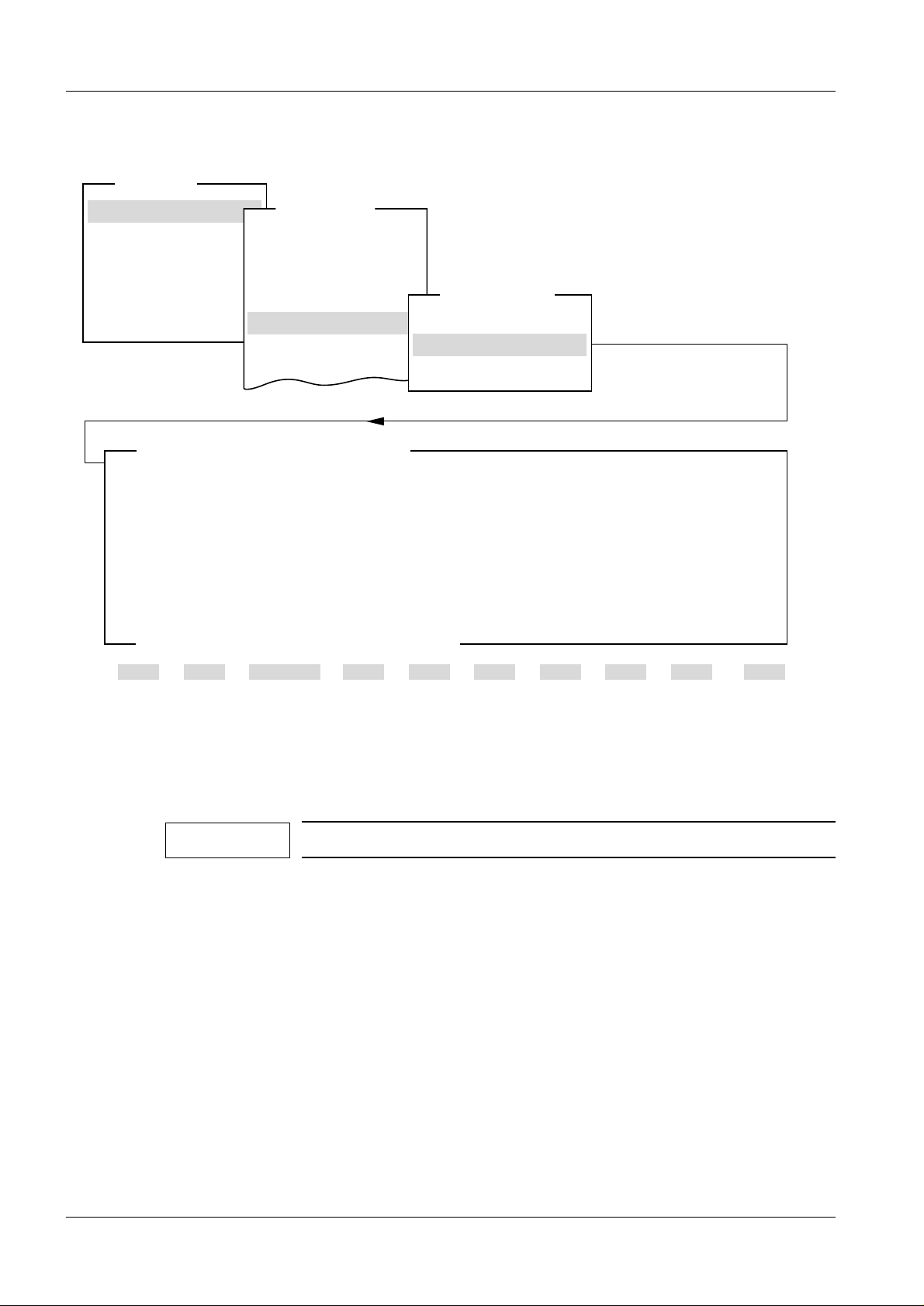
Fig. 1
System type indicates type of stand, generator and control panel. Collimator indicates
type of collimator in the stand. Collimator choice (Automatic or Maual) valid only for
MAMMOMAT 1000.
When MAMMOMAT 1000 is selected, the tungsten anode is automatically deselected,
and furthermore, the
Siemens-Elema AB Register 5 SPB7-230.114.02 Page 1 of 56 Mammomat 1000/3000
Solna, Sweden Rev. 01 03.99 SPS-UD Service Program
Anode
menu cannot be selected.
MAM00449
Page 8
2 - 2 Adjustment and Service PC Programs
NOTICE
Anode 3
Main menu
Configuration
Service
Normal mode
Test DUEP Communic.
Backup
Quit
Anode
Configuration
System type
Anode
Show configuration file
Save configuration file
Iontomat
Miscellaneous
Filament
Tungsten anode
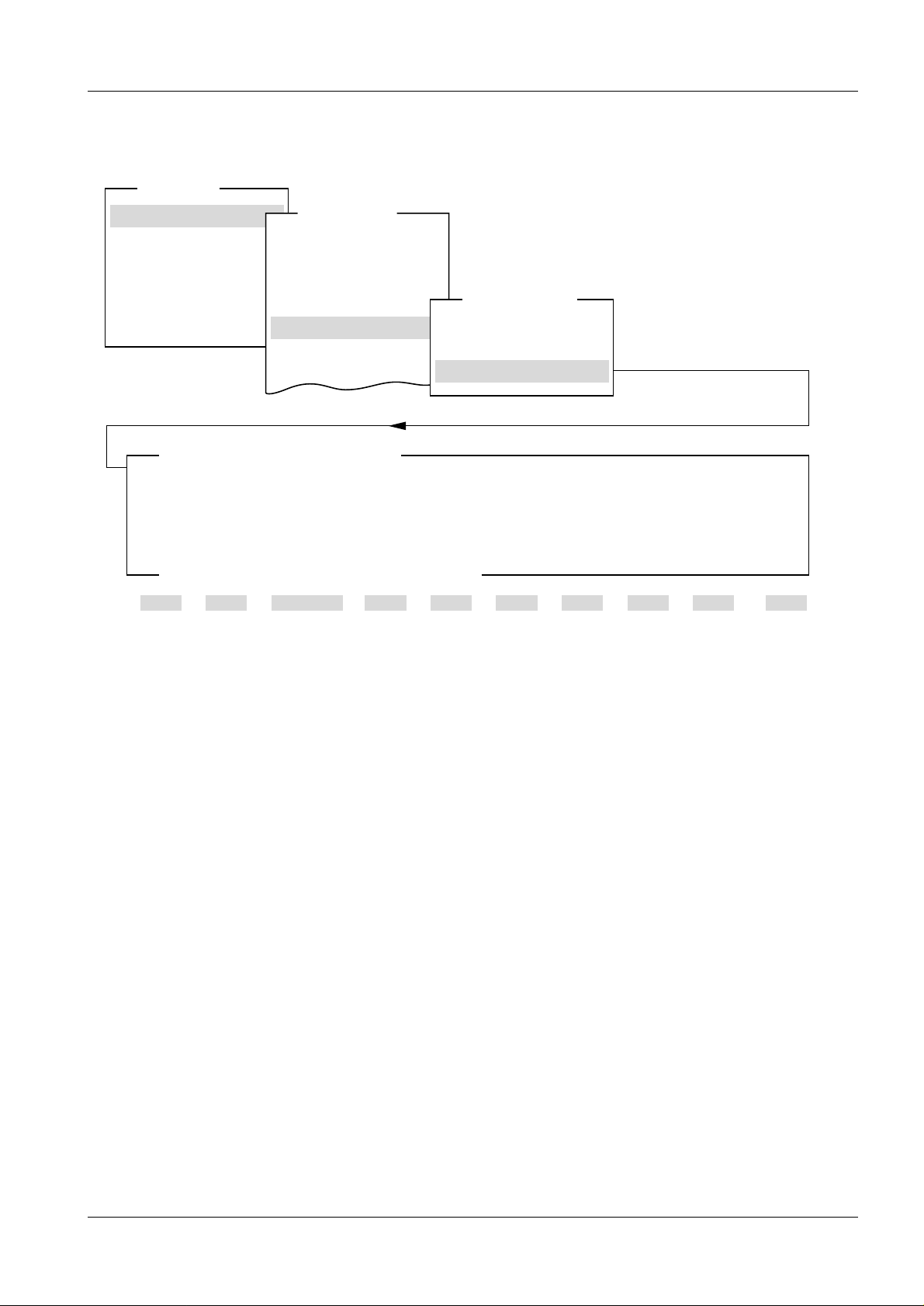
NOTE: When changing the anode selection, always check the power setting.
<ESC> to exit, <space to toggle entry>
1 Help 2 Save 3 45678910Quit
Fig. 2
Enable
Activation and deactivation of the tungsten anode. When deactivated, it will not be
possible to select W/Rh alternative on the control panel.
This menu is not selectable when t he s ystem type i s set t o M1000.
MAM00454
Mammomat 1000/3000 Register 5 SPB7-230.114.02 Page 2 of 56 Siemens-Elema AB
Service Program Rev. 01 03.99 SPS-UD Solna, Sweden
Page 9
Adjustment and Service PC Programs 2 - 3
NOTICE
Show configuration file 3
Main menu
Configuration
Service
Normal mode
Test DUEP Communic.
Backup
Quit
Show file mammo.cfg
Configuration
System type
Anode
Show configuration file
Save configuration file
Iontomat
Miscellaneous
Filament
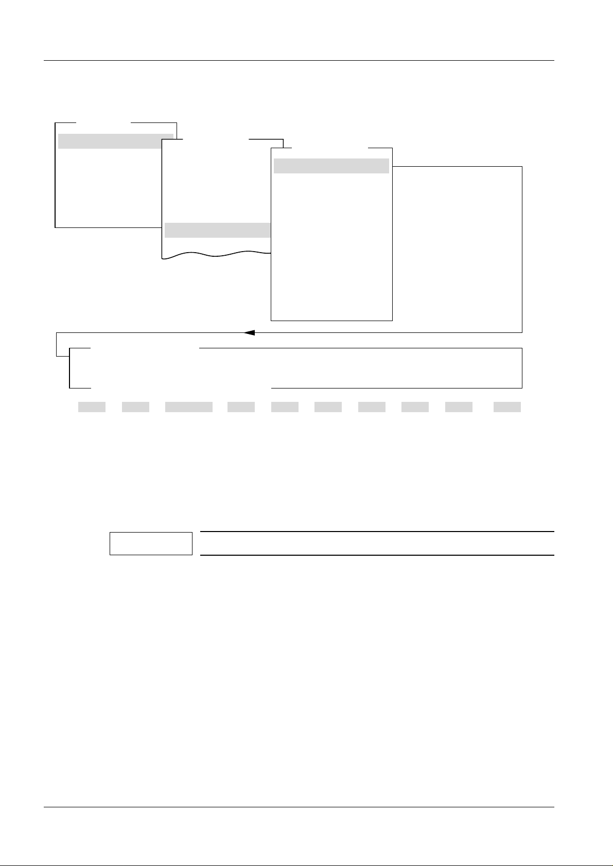
Fig. 3
System M3000
Power
Molly large focus 3.75 kW Tungsten large focus 4.70 kW
Molly small focus 0.70 kW Tungsten small focus 0.85 kW
Filament current
Molly large focus 6500 mA Tungsten large focus 6500 mA
Molly small focus 6500 mA Tungsten small focus 6500 mA
Tube current reduction ON
Power supply OFF
Sensitivity Wing 1
H 11.0
D 11.0
Correction curve A
Sensitivity correction
no grid
grid
magnification
Optimized compression
OPCOMP 18*24 and 24*30 ON
OPCOMP mag 15 and 18 OFF
Auto limits P1 30mm P2 45mm P3 60mm
Any key to continue
1 Help 2 3 45678910Quit
Tungsten Anode
H AD
ENABLED
Reduction time: 100 ms
Wing 2
11.0
11.0
Wing 1
0
0
0 0
Wing 2
0
0
Collimator AUTOMATIC
This menu displays the system configuration as stored in the “mammo.cfg” file.
MAM00450
All data are examples and may vary for the unit in question.
Siemens-Elema AB Register 5 SPB7-230.114.02 Page 3 of 56 Mammomat 1000/3000
Solna, Sweden Rev. 01 03.99 SPS-UD Service Program
Page 10

2 - 4 Adjustment and Service PC Programs
Save configuration file 3
Main menu
Configuration
Service
Normal mode
Test DUEP Communic.
Backup
Quit
Save configuration -> mammo.cfg
Configuration
System type
Anode
Show configuration file
Save configuration file
Iontomat
Miscellaneous
Filament
System M3000 Tungsten Anode
Power
Molly large focus 3.75 kW Tungsten large focus 4.70 kW
Molly small focus 0.70 kW Tungsten small focus 0.85 kW
Filament current
Molly large focus 6500 mA Tungsten large focus 6500 mA
Molly small focus 6500 mA Tungsten small focus 6500 mA
Tube current reduction ON
Power supply OFF
Sensitivity Wing 1
H 11.0
D 11.0
Correction curve A
Sensitivity correction
no grid
grid
magnification
Optimized compression
OPCOMP 18*24 and 24*30 ON
OPCOMP mag 15 and 18 OFF
Auto limits P1 30mm P2 45mm P3 60mm
<ESC> to exit, <F2> save list in file mammo.cfg
1 Help 2 Save 3 45678910Quit
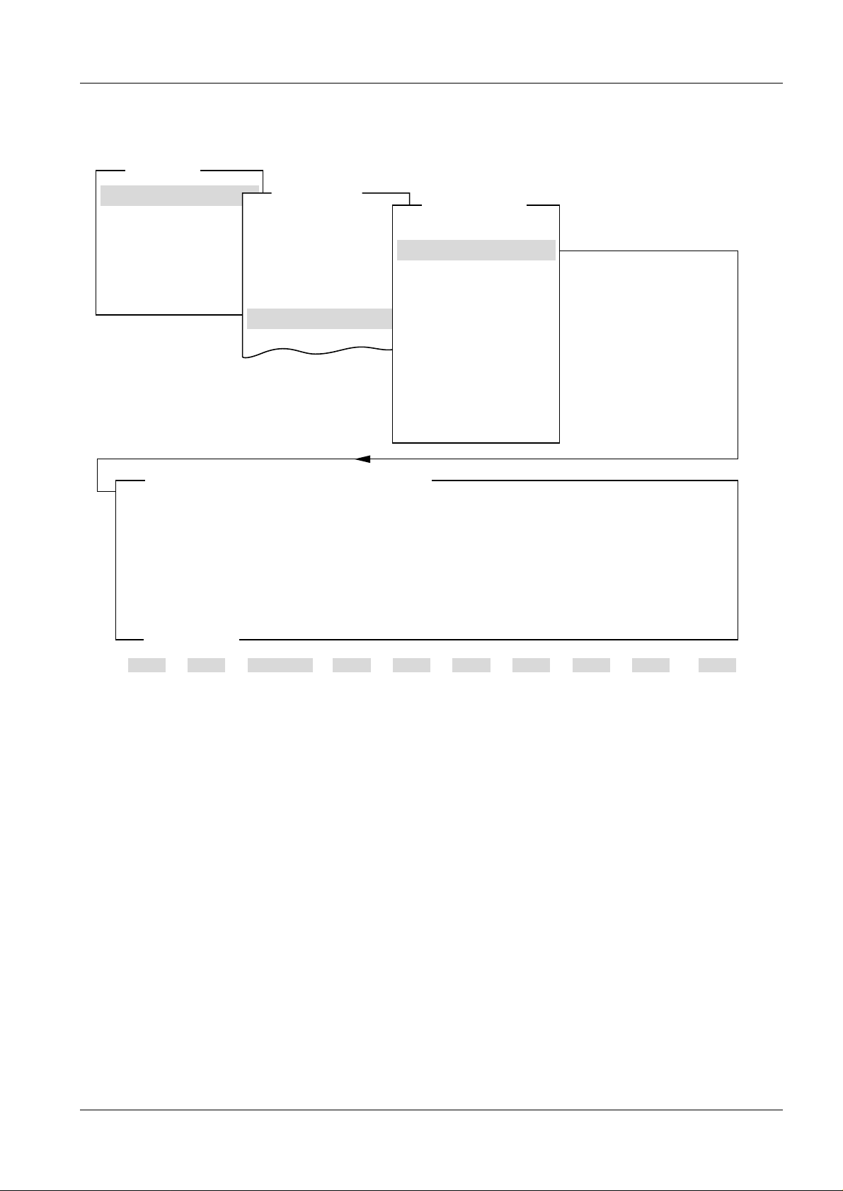
Fig. 4
H AD
ENABLED
Reduction time: 100 ms
Wing 1
0
0
00
Collimator AUTOMATIC
Wing 2
11.0
11.0
Wing 2
0
0
MAM00451
This menu is used for storing information about the system confi guration in the
“mammo.cfg” file.
The file will be stor ed on the hard disk of the service PC at current directory, if the service
PC program is running from this.
If the service PC program is running from a floppy disk, the file wil l be stored on this.
Mammomat 1000/3000 Register 5 SPB7-230.114.02 Page 4 of 56 Siemens-Elema AB
Service Program Rev. 01 03.99 SPS-UD Solna, Sweden
Page 11
Adjustment and Service PC Programs 2 - 5
NOTICE
IONTOMAT PM, sensitivity 3
Main menu
Configuration
Service
Normal mode
Test DUEP Communic.
Backup
Quit
IONTOMAT PM - Sensitivity
Wing 1 11.0
Wing 2 11.0 11.0
Configuration
System type
Anode
Show configuration file
Save configuration file
Iontomat
Miscellaneous
Filament
IONTOMAT PM
Sensitivity
Sensitivity correction
Correction curve
HD
11.0
Valid entries from 0 to 31 in 1/2 E.P.
Input of decimal point not required!
<ESC> to exit, <TAB> move to next entry field
1 Help 2 Save 3 45678910Quit
Fig. 5
Indicates the sensiti vity of the IONTOMAT channel for high speed (H) and high resolution
screen (D) respectively.
Values from 0 to 31 can be entered in 1/2 exposure points.
If only one type of film-screen-combination is used, set both val ues (for H and D) to the same level.
Also see “Installation and Start-Up Inst ructions”.
MAM00455
Siemens-Elema AB Register 5 SPB7-230.114.02 Page 5 of 56 Mammomat 1000/3000
Solna, Sweden Rev. 01 03.99 SPS-UD Service Program
Page 12
2 - 6 Adjustment and Service PC Programs
NOTICE
IONTOMAT PM, sensitivity correction 3
Main menu
Configuration
Service
Normal mode
Test DUEP Communic.
Backup
Quit
IONTOMAT PM - Sensitivity correction
Without grid 0
With grid 0
Magnification 0
Configuration
System type
Anode
Show configuration file
Save configuration file
Iontomat
Miscellaneous
Filament
IONTOMAT PM
Sensitivity
Sensitivity correction
Correction curve
Wing 1 Wing 2
0
0
0
Valid entries from -8 to 8 in 1/2 E.P.
For pos entries 1st digit is <space> for neg entries type <->.
Input of decimal point not required!
<ESC> to exit, <TAB> move to next entry field
1 Help 2 Save 3 45678910Quit
Fig. 6
Indicates the sensitivity correction for different types of object tables.
All data are examples and may vary for the unit in question.
MAM00456
Mammomat 1000/3000 Register 5 SPB7-230.114.02 Page 6 of 56 Siemens-Elema AB
Service Program Rev. 01 03.99 SPS-UD Solna, Sweden
Page 13
Adjustment and Service PC Programs 2 - 7
IONTOMAT PM, correction curve 3
Main menu
Configuration
Service
Normal mode
Test DUEP Communic.
Backup
Quit
IONTOMAT PM - Correction curve
Configuration
System type
Anode
Show configuration file
Save configuration file
Iontomat
Miscellaneous
Filament
Curve number
Speed H A
Speed D A
IONTOMAT PM
Sensitivity
Sensitivity correction
Correction curve
<ESC> to exit, <TAB> move to next entry field
1 Help 2 Save 3 45678910Quit
Fig. 7
Indicates which correction curve shall be used for high speed (H) and high resolution (D)
screen respectively.
For further information, please refer to the installation manual, chapter “Start-up and functional test of the IONTOMAT PM”.
MAM00457
Siemens-Elema AB Register 5 SPB7-230.114.02 Page 7 of 56 Mammomat 1000/3000
Solna, Sweden Rev. 01 03.99 SPS-UD Service Program
Page 14
2 - 8 Adjustment and Service PC Programs
NOTICE
Miscellaneous, DLF switch 3
Main menu
Configuration
Service
Normal mode
Test DUEP Communic.
Backup
Quit
Dynamic learn filament
Configuration
System type
Anode
Show configuration file
Save configuration file
Iontomat
Miscellaneous
Filament
Miscellaneous
DLF switch
Reduction of power
Tube mA reduction
Printer
Power supply
Potentiometer check
Panel programming
Auto limits
Cassette loaded check
Illumination time
Version info
Switch is ON
<ESC> to exit, <space> to toggle entry
1 Help 2 Save 3 45678910Quit
Fig. 8
Activation and deactivation of the filament current adapti on. When activated, the adapti on
takes place after a total of ten exposures has been made wit h the actual focus, i f the deviation of the average value from the nominal value is within -15% to + 5%.
Without any exceptional reason, the DLF-switch shall be “ON”.
MAM00458
Mammomat 1000/3000 Register 5 SPB7-230.114.02 Page 8 of 56 Siemens-Elema AB
Service Program Rev. 01 03.99 SPS-UD Solna, Sweden
Page 15
Adjustment and Service PC Programs 2 - 9
Miscellaneous, reduction of power 3
Main menu
Configuration
Service
Normal mode
Test DUEP Communic.
Backup
Quit
Reduction of power depending on line quality
Configuration
System type
Anode
Show configuration file
Save configuration file
Iontomat
Miscellaneous
Filament
Miscellaneous
DLF switch
Reduction of power
Tube mA reduction
Printer
Power supply
Potentiometer check
Panel programming
Auto limits
Cassette loaded check
Illumination time
Version info
Tube is P40MoW
Select nominal line voltage
240 V <-- with cursor keys and <Enter>
Type in line impedance
Power is 4.70 kW TUNGSTEN
3.75 kW MOLLY
<ESC> to exit
1 Help 2 Save 3 45678910Quit
Fig. 9
Calculates the maximum power allowed with regard to nominal voltage and line impedance.
Select the line voltage a nd type in t he line impeda nce you have meas ured. The proce ssor
will calculate the power and wi ll indicat e whe n the power must be redu ced be cause of the
line impedance.
Finally press <F2> to save.
MAM00459
Siemens-Elema AB Register 5 SPB7-230.114.02 Page 9 of 56 Mammomat 1000/3000
Solna, Sweden Rev. 01 03.99 SPS-UD Service Program
Page 16
2 - 10 Adjustment and Service PC Programs
Miscellaneous, tube current reduction 3
Main menu
Configuration
Service
Normal mode
Test DUEP Communic.
Backup
Quit
Tube current reduction (TCR) at short exposure time (100ms)
Configuration
System type
Anode
Show configuration file
Save configuration file
Iontomat
Miscellaneous
Filament
Miscellaneous
DLF switch
Reduction of power
Tube mA reduction
Printer
Power supply
Potentiometer check
Panel programming
Auto limits
Cassette loaded check
Illumination time
Version info
TCR switch is ON
Exposure time with 50 mA tube current is 100 ms
<ESC> to exit, <space> to toggle entry
1 Help 2 Save 3 45678910Quit
Fig. 10
Activation and deactivation of TCR.
When this function is activated, the tube current is reduced to 50 mA, in IONTOMAT
mode, at the start of exposure.
The time for the reduction is always 100 ms.
MAM00460
Mammomat 1000/3000 Register 5 SPB7-230.114.02 Page 10 of 56 Siemens-Elema AB
Service Program Rev. 01 03.99 SPS-UD Solna, Sweden
Page 17
Adjustment and Service PC Programs 2 - 11
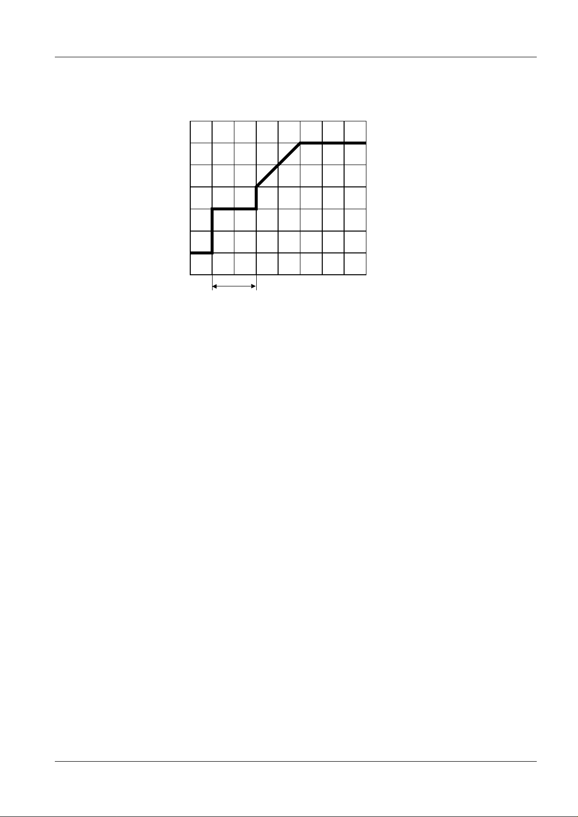
If TCR switch is “ON”, the tube current will look like this: 3
50 mA
approx.
100 ms
MAM00461
Fig. 11
Siemens-Elema AB Register 5 SPB7-230.114.02 Page 11 of 56 Mammomat 1000/3000
Solna, Sweden Rev. 01 03.99 SPS-UD Service Program
Page 18
2 - 12 Adjustment and Service PC Programs
Miscellaneous, printer 3
Main menu
Configuration
Service
Normal mode
Test DUEP Communic.
Backup
Quit
Configuration
System type
Anode
Show configuration file
Save configuration file
Iontomat
Miscellaneous
Filament
Miscellaneous
DLF switch
Reduction of power
Tube mA reduction
Printer
Power supply
Potentiometer check
Panel programming
Auto limits
Cassette loaded check
Illumination time
Version info
Printer type selection
Actual setting
<ESC> to exit, <space> to toggle entry
1 Help 2 Save 3 45678910Quit
Fig. 12
No print
Select no print, RS 232C or PC print.
RS 232C is used when the printer is connected directly to the generator.
PC print is used when the printer is connected to the system via a PC connected to the
generator.
MAM00462
Mammomat 1000/3000 Register 5 SPB7-230.114.02 Page 12 of 56 Siemens-Elema AB
Service Program Rev. 01 03.99 SPS-UD Solna, Sweden
Page 19
Adjustment and Service PC Programs 2 - 13
Miscellaneous, power supply 3
Main menu
Configuration
Service
Normal mode
Test DUEP Communic.
Backup
Quit
Power supply
Configuration
System type
Anode
Show configuration file
Save configuration file
Iontomat
Miscellaneous
Filament
Miscellaneous
DLF switch
Reduction of power
Tube mA reduction
Printer
Power supply
Potentiometer check
Panel programming
Auto limits
Cassette loaded check
Illumination time
Version info
Switch is
<ESC> to exit, <space> to toggle entry
1 Help 2 Save 3 45678910Quit
Fig. 13
OFF
Indicates whether the Mammomat is powered by an external power supply (e.g. Power
Aid) or not.
MAM00463
Siemens-Elema AB Register 5 SPB7-230.114.02 Page 13 of 56 Mammomat 1000/3000
Solna, Sweden Rev. 01 03.99 SPS-UD Service Program
Page 20
2 - 14 Adjustment and Service PC Programs
Miscellaneous, potentiometer check 3
Main menu
Configuration
Service
Normal mode
Test DUEP Communic.
Backup
Quit
Potentiometer check
Configuration
System type
Anode
Show configuration file
Save configuration file
Iontomat
Miscellaneous
Filament
Miscellaneous
DLF switch
Reduction of power
Tube mA reduction
Printer
Power supply
Potentiometer check
Panel programming
Auto limits
Cassette loaded check
Illumination time
Version info
A/D value
<ESC> to exit
1 Help 2 Save 3 45678910Quit
Fig. 14
032A
Sampled calibration value for the return current through the four potentiometers “preset
force”, “preset angle”, “thickness” and “angle”. This retur n current is continuously monitored by the system. Should the return current deviate too much from the calibration
value, this is probably due to a faulty potentiometer or due to a contact failure with one of
the potentiometers, which results in error code 825 or 826.
MAM00464
Mammomat 1000/3000 Register 5 SPB7-230.114.02 Page 14 of 56 Siemens-Elema AB
Service Program Rev. 01 03.99 SPS-UD Solna, Sweden
Page 21
Adjustment and Service PC Programs 2 - 15
NOTICE
NOTICE
Miscellaneous, panel programming 3
Main menu
Configuration
Service
Normal mode
Test DUEP Communic.
Backup
Quit
Panel programming
Configuration
System type
Anode
Show configuration file
Save configuration file
Iontomat
Miscellaneous
Filament
Miscellaneous
DLF switch
Reduction of power
Tube mA reduction
Printer
Power supply
Potentiometer check
Panel programming
Auto limits
Cassette loaded check
Illumination time
Version info
Switch is
<ESC> to exit, <space> to toggle entry
1 Help 2 Save 3 45678910Quit
Fig. 15
ON
Activation and deactivation of the Memory button on the control panel, making it possible
to change the program settings for the four programs.
With the switch “OFF”, any change of data is blocked.
Should be switched “OFF” only if customer demands.
This menu is not selectable when the sys tem t ype is set to M1000.
MAM00465
Siemens-Elema AB Register 5 SPB7-230.114.02 Page 15 of 56 Mammomat 1000/3000
Solna, Sweden Rev. 01 03.99 SPS-UD Service Program
Page 22
2 - 16 Adjustment and Service PC Programs
NOTICE
Miscellaneous, auto limits 3
Main menu
Configuration
Service
Normal mode
Test DUEP Communic.
Backup
Quit
Auto limits
Configuration
System type
Anode
Show configuration file
Save configuration file
Iontomat
Miscellaneous
Filament
Auto limits
Program 1
Program 2 45 mm
Program 3 60 mm
Miscellaneous
DLF switch
Reduction of power
Tube mA reduction
Printer
Power supply
Potentiometer check
Panel programming
Auto limits
Cassette loaded check
Illumination time
Version info
30 mm
Valid entries from 0 to 180 mm
<ESC> to exit, <TAB> move to next entry field
1 Help 2 Save 3 45678910Quit
Fig. 16
Set the upper thickness limits for the programs 1-3.
Program 1 has a lower limit of 0 and Program 4 has a higher limit of 180 mm.
Supposing the above used values are stored in auto mode:
• The program key P1 is automatically selected with a compression thickness between 0
and 30 mm.
• The program key P2 is automatically selected with a compression thickness between 31
and 45 mm.
• The program key P3 is automatically selected with a compression thickness between 46
and 60 mm.
• The program key P4 is automatically selected with a compression thickness more than
60 mm.
MAM00466
This menu is not selectable when t he s ystem type i s set t o M1000.
Mammomat 1000/3000 Register 5 SPB7-230.114.02 Page 16 of 56 Siemens-Elema AB
Service Program Rev. 01 03.99 SPS-UD Solna, Sweden
Page 23
Adjustment and Service PC Programs 2 - 17
Miscellaneous, cassette loaded check 3
Main menu
Configuration
Service
Normal mode
Test DUEP Communic.
Backup
Quit
Cassette loaded check
Configuration
System type
Anode
Show configuration file
Save configuration file
Iontomat
Miscellaneous
Filament
Miscellaneous
DLF switch
Reduction of power
Tube mA reduction
Printer
Power supply
Potentiometer check
Panel programming
Auto limits
Cassette loaded check
Illumination time
Version info
Switch is
<ESC> to exit, <SPACE> to toggle entry
1 Help 2 Save 3 45678910Quit
Fig. 17
ON
Activate or deactivate the check that a cassette is loaded/reloaded.
With this function activa ted, the casset te symbol on the contr ol panel will light up when the
inserted cassette has been exposed or if no cassette is insert ed a t all. Exposure release
is in this case blocked. The film cassette must be exchanged after each exposure.
During service it might be helpful to set the switch to “OFF”. When finishing service, do not
forget to set it back to the original setting.
MAM00467
Siemens-Elema AB Register 5 SPB7-230.114.02 Page 17 of 56 Mammomat 1000/3000
Solna, Sweden Rev. 01 03.99 SPS-UD Service Program
Page 24
2 - 18 Adjustment and Service PC Programs
Miscellaneous, illumination time 3
Main menu
Configuration
Service
Normal mode
Test DUEP Communic.
Backup
Quit
Illumination time
Configuration
System type
Anode
Show configuration file
Save configuration file
Iontomat
Miscellaneous
Filament
Miscellaneous
DLF switch
Reduction of power
Tube mA reduction
Printer
Power supply
Potentiometer check
Panel programming
Auto limits
Cassette loaded check
Illumination time
Version info
Illumination time
<ESC> to exit
1 Help 2 Save 3 45678910Quit
Fig. 18
20 s
Duration of switched-on field light (collimator lamp). 1-99 s.
Duration should be set according to customer’s wishes.
MAM00468
Mammomat 1000/3000 Register 5 SPB7-230.114.02 Page 18 of 56 Siemens-Elema AB
Service Program Rev. 01 03.99 SPS-UD Solna, Sweden
Page 25
Adjustment and Service PC Programs 2 - 19
Miscellaneous, version info 3
Main menu
Configuration
Service
Normal mode
Test DUEP Communic.
Backup
Quit
Version info
Configuration
System type
Anode
Show configuration file
Save configuration file
Iontomat
Miscellaneous
Filament
Miscellaneous
DLF switch
Reduction of power
Tube mA reduction
Printer
Power supply
Potentiometer check
Panel programming
Auto limits
Cassette loaded check
Illumination time
Version info
MASTER PANEL STAND
Version:
Date: 94-02-15 93-11-23 94-03-05
Any key to continue
1 Help 2 3 45678910Quit
Fig. 19
2.1 1.2 1.4
Shows software versions and dates for the three computers in the system.
MAM00469
Siemens-Elema AB Register 5 SPB7-230.114.02 Page 19 of 56 Mammomat 1000/3000
Solna, Sweden Rev. 01 03.99 SPS-UD Service Program
Page 26
2 - 20 Adjustment and Service PC Programs
NOTICE
Filament 3
Main menu
Configuration
Service
Normal mode
Test DUEP Communic.
Backup
Quit
Filament
Filament current @ 25 kV
Large focus molly 6900
Large focus tungsten 6500
Small focus molly 7500
Small focus tungsten 6500
Configuration
System type
Anode
Show configuration file
Save configuration file
Iontomat
Miscellaneous
Filament
<ESC> to exit, <TAB> to move to next entry field
1 Help 2 Save 3 45678910Quit
Fig. 20
Learn
Indicates the adapted filament current of both anode materials for large and small focus.
Adaption exposures for the filament current are also made in this menu.
Pressing F3 sets the exposure parameters on the control panel, and subsequently press-
ing Alt-F6 starts the exposure. Repeat this procedure until the tube-current deviation is
within ±5%.
If the tube has been replaced, program the filament current value 200 mA lower than the
value stated in the test certificat e as a preadjust ment. (e.g. If tube value is 6900, pr ogram
6700.)
If a new filament current ha s been entered you must sav e the new value (press F2) before
the learn filament is performed.
The Dynamic-Learn-Filament may change this adjustment. But
the DLF will only learn when the exposure time is longer than 60
ms.
MAM00470
Mammomat 1000/3000 Register 5 SPB7-230.114.02 Page 20 of 56 Siemens-Elema AB
Service Program Rev. 01 03.99 SPS-UD Solna, Sweden
Page 27

Adjustment and Service PC Programs 2 - 21
Power 3
Main menu
Configuration
Service
Normal mode
Test DUEP Communic.
Backup
Quit
Configuration
System type
Anode
Show configuration file
Save configuration file
Iontomat
Miscellaneous
Filament
Power
Clock
Compression
Lift
Rotation
Grid speed
Beam limiting device
Power
Power
Large focus molly 3.75 kW
Large focus tungsten 4.70 kW
Small focus molly .70 kW
Small focus tungsten .85 kW
Input of decimal point not required!
<ESC> to exit, <TAB> move to next entry field
1 Help 2 Save 3 45678910Quit
Fig. 21
Indicates the maximum power for large and small focus of both anode materials.
The values programmed must not exceed the values stated above.
These maximum values are only possible when the line impedance is not too high.
MAM00471
Siemens-Elema AB Register 5 SPB7-230.114.02 Page 21 of 56 Mammomat 1000/3000
Solna, Sweden Rev. 01 03.99 SPS-UD Service Program
Page 28

2 - 22 Adjustment and Service PC Programs
Clock 3
Main menu
Configuration
Service
Normal mode
Test DUEP Communic.
Backup
Quit
Configuration
System type
Anode
Show configuration file
Save configuration file
Iontomat
Miscellaneous
Filament
Power
Clock
Compression
Lift
Rotation
Grid speed
Beam limiting device
Clock
PC date = 25.05.94
PC time = 13:31.08
Mammo date = 18.11.93
Mammo time = 14:19.11
Oscillator off
Press <F2> to set mammo clock to PC clock
and to switch oscillator on.
<ESC> to exit
1 Help 2 Set 3 45678910Quit
Fig. 22
Off
Indicates date and time.
Date and time should be correct because they are used when storing an error message
and marking films.
MAM00472
Mammomat 1000/3000 Register 5 SPB7-230.114.02 Page 22 of 56 Siemens-Elema AB
Service Program Rev. 01 03.99 SPS-UD Solna, Sweden
Page 29

Adjustment and Service PC Programs 2 - 23
Compression, configuration 3
Main menu
Configuration
Service
Normal mode
Test DUEP Communic.
Backup
Quit
Configuration
System type
Anode
Show configuration file
Save configuration file
Iontomat
Miscellaneous
Filament
Power
Clock
Compression
Lift
Rotation
Grid speed
Beam limiting device
Compression
Configuration
Calibration
Optimized compression
Compression configuration
Slow compression
Compression speed
Decompression speed
<ESC> to exit, <TAB> move to next entry field
1 Help 2 Save 3 45678910Quit
Fig. 23
3 kp/s
40 mm/s
60 mm/s
Slow compression 3
When compression force exceeds 1 kg (10N) , the f orce i ncrease p er s econd i s regul ated.
The value indicates the reference value for the regulation.
Compression speed 3
Speed of compression plate in mm/s during compression.
Admissible values: 1 - 80. A higher value will not generate any error, nor wil l it cause any
speed increase.
Decompression speed 3
MAM00473
Speed of compression plate in mm/s during decompression. Same values as above.
Siemens-Elema AB Register 5 SPB7-230.114.02 Page 23 of 56 Mammomat 1000/3000
Solna, Sweden Rev. 01 03.99 SPS-UD Service Program
Page 30

2 - 24 Adjustment and Service PC Programs
Compression, calibration 3
Main menu
Configuration
Service
Normal mode
Test DUEP Communic.
Backup
Quit
Configuration
System type
Anode
Show configuration file
Save configuration file
Iontomat
Miscellaneous
Filament
Power
Clock
Compression
Lift
Rotation
Grid speed
Beam limiting device
Compression
Configuration
Calibration
Optimized compression
Compression calibration
Force = 0 N
Force = 200 N
Preset force = 0 N
Preset force = 200 N
Thickness bottom
Thickness bottom
Thickness top
Thickness top 180 mm
<ESC> to exit, <TAB> move to next entry field
1 Help 2 Save 3 45678910Quit
Fig. 24
Calibrate
006D
02A4
00
FF
01AC
0 mm
039B
Force = 0 N 3
Sampled calibration value for the forc e sensor at a compression f orce of 0 N after running
the compression plate downwards. Stop before reaching the object table.
Force = 200 N 3
Sampled calibration value for the force sensor at a compression force of 200 N. Put the
scale on the object table and compress to 200 N by motor only. If 200 N is exceeded,
restart from 0 N!
MAM00474
Mammomat 1000/3000 Register 5 SPB7-230.114.02 Page 24 of 56 Siemens-Elema AB
Service Program Rev. 01 03.99 SPS-UD Solna, Sweden
Page 31

Adjustment and Service PC Programs 2 - 25
Preset force = 0 N 3
Sampled calibration value with the preset force potentiometer set to minimum (turned
counter clockwise to end position).
Preset force = 200 N 3
Sampled calibration value with the preset force potentiometer set to maximum (turned
clockwise to end position).
Thickness bottom (HEX) 3
Sampled calibration value for the thickness sensor, when the compression plate is in bottom position.
Thickness bottom (mm) 3
Measured distance between compression plate and object table, when the compression
plate is in bottom position. If the compression pla te reaches the object table (normal
case), type in 0.
Thickness top (HEX) 3
Sampled calibration value for the thickness sensor, when the compression plate is in
uppermost position.
Thickness top (mm) 3
Measured distance between compression plate and object table, when the compression
plate is in uppermost position. Measure with a rule r.
Siemens-Elema AB Register 5 SPB7-230.114.02 Page 25 of 56 Mammomat 1000/3000
Solna, Sweden Rev. 01 03.99 SPS-UD Service Program
Page 32

2 - 26 Adjustment and Service PC Programs
NOTICE
Compression, optimized 3
Main menu
Configuration
Service
Normal mode
Test DUEP Communic.
Backup
Quit
Configuration
System type
Anode
Show configuration file
Save configuration file
Iontomat
Miscellaneous
Filament
Power
Clock
Compression
Lift
Rotation
Grid speed
Beam limiting device
Compression
Configuration
Calibration
Optimized compression
Best compression table
OPCOMP code 18 x 24 and 24 x 30
OPCOMP code mag 15 and 18
Tautness factor 18x24
Tautness factor 24x30
Tautness factor mag 15
Tautness factor mag 18
<ESC> to exit, <TAB> move to next entry field
1 Help 2 Save 3 45678910Quit
Fig. 25
5137
1234
70
70
70
70
Loop count compare
Sample time diff
Flex factor 18x24
Flex factor 24x30
Flex factor mag 15
Flex factor mag 18 74
72
98
74
4
4
OPCOMP code 18x24 and 24x30 3
Enable or disable OPCOMP. A correct input code will enable OPCOMP.
OPCOMP is aviable as an option for M1000.
Adapting OPCOMP 3
MAM00475
If the factory-set OPCOMP is not to the customer’s satisfaction, an adjustment can be
done with the tautness fact ors in the “ Best compre ssion table ”. A lower taut ness valu e will
increase the compression force and vice versa.
Mammomat 1000/3000 Register 5 SPB7-230.114.02 Page 26 of 56 Siemens-Elema AB
Service Program Rev. 01 03.99 SPS-UD Solna, Sweden
Page 33

Adjustment and Service PC Programs 2 - 27
NOTICE
Increase/decrease the tautness fact or by e.g. 10 the first time. Let the customer use this
setting for at least two weeks, before further changes are made.
OPCOMP has been thoroughly tested by Siemens. If any factors
are changed, OPCOMP will no longer be an optimization of com-
pression force and image quality according to Siemens’ clinical
test.
Tautness factor 18x24 3
This factor determines how hard a breast is pressed. Lower tau tness factor gives more
pressure to the breast.
Tautness factor 24x30 3
This factor determines how hard a breast is pressed. Lower tau tness factor gives more
pressure to the breast.
Tautness factor mag 15 (not used) 3
This factor determines how hard a breast is pressed when a magnification table 1.5 is
attached. Lower tautness factor gives more pressure to the breast.
Tautness factor mag 18 (not used) 3
This factor determines how hard a breast is pressed when a magnification table 1.8 is
attached. Lower tautness factor gives more pressure to the breast.
Loop count compare 3
Number of times that OPCOMP condition should be fulfilled to stop compression.
Sample time diff 3
Table index difference (time) between sample s of thi ckness, used to determine if
OPCOMP condition is fulfilled.
Flex factor 18x24 3
A value of the mechanical system’s flexibility. The value is usually factory defined.
Flex factor 24x30 3
A value of the mechanical system’s flexibility. The value is usually factory defined.
Flex factor mag 15 (not used) 3
A value of the mechanical system’ s flexibility for magnifi cation table 1.5. The value is usually factory defined.
Flex factor mag 18 (not used) 3
A value of the mechanical system’ s flexibility for magnifi cation table 1.8. The value is usually factory defined.
Siemens-Elema AB Register 5 SPB7-230.114.02 Page 27 of 56 Mammomat 1000/3000
Solna, Sweden Rev. 01 03.99 SPS-UD Service Program
Page 34

2 - 28 Adjustment and Service PC Programs
Lift 3
Main menu
Configuration
Service
Normal mode
Test DUEP Communic.
Backup
Quit
Configuration
System type
Anode
Show configuration file
Save configuration file
Iontomat
Miscellaneous
Filament
Power
Clock
Compression
Lift
Rotation
Grid speed
Beam limiting device
Lift
Upward acceleration 1
Downward acceleration 1
Upward brake 10
Downward brake 10
Upward start 5
Downward start 5
Upward stop 40
Downward stop 40
<ESC> to exit, <TAB> move to next entry field
1 Help 2 Save 3 45678910Quit
Fig. 26
Up acceleration 3
To attai n desired acceleration of the lift movement, the pulse width of the motor- control
signal is ramped up. The digit is a measure of the acceleration rate ate the start of the lift
movement in upward direction. It indicates the increase of the duty cycle on the signal for
each change event, which occurs every 10 ms.
Admissible values: 1 - 99. The higher the value the faster the acceleration.
MAM00477
Mammomat 1000/3000 Register 5 SPB7-230.114.02 Page 28 of 56 Siemens-Elema AB
Service Program Rev. 01 03.99 SPS-UD Solna, Sweden
Page 35

Adjustment and Service PC Programs 2 - 29
Down acc 3
Same as above, but for downward lift movement.
Admissible values: 1 - 99
Up brake 3
To attain desired deacceleration of the lift movement, the pulse width of the motor-control
signal is ramped down. The digit is a measure of at which deaccel erati on rate the upward
lift movement shall stop. It indicates the decr ease of the duty cycle on the signal for each
change event, which occurs every 10 ms.
Admissible values: 1 - 99. The higher the value the faster it slows the motor down.
Down brake 3
Same as above, but for downward lift movement.
Admissible values: 1 - 99
Up start 3
To enable instantaneous start of the upward movement, the motor-control signal starts
with a predetermined pulse width. The digit is a measure of the size o f the pulse width (in
percentage of the supply voltage). Increase val ue, if movement does not start instantaneously, decrease value if movement starts too abruptly.
Admissible values: 1 - 99
Down start 3
Same as above, but for downward movement.
Admissible values: 1 - 99
Up stop 3
At upward movement, the parameter indicates at which duty cycle the ramping of the
pulse width is interrupted and the pulse wid th set to zero.
Admissible values: 1 - 99
Down stop 3
Same as above, but for downward movement.
Admissible values: 1 - 99
Siemens-Elema AB Register 5 SPB7-230.114.02 Page 29 of 56 Mammomat 1000/3000
Solna, Sweden Rev. 01 03.99 SPS-UD Service Program
Page 36

2 - 30 Adjustment and Service PC Programs
Rotation, configuration 3
Main menu
Configuration
Service
Normal mode
Test DUEP Communic.
Backup
Quit
Configuration
System type
Anode
Show configuration file
Save configuration file
Iontomat
Miscellaneous
Filament
Power
Clock
Compression
Lift
Rotation
Grid speed
Beam limiting device
Rotation
Configuration
Calibration
Rotation configuration
Brake distance 6
<ESC> to exit
1 Help 2 Save 3 45678910Quit
Fig. 27
The brake distance of the tube, i.e. how many degrees before wanted stop angle that
rotation is being slowed down.
MAM00478
Mammomat 1000/3000 Register 5 SPB7-230.114.02 Page 30 of 56 Siemens-Elema AB
Service Program Rev. 01 03.99 SPS-UD Solna, Sweden
Page 37

Adjustment and Service PC Programs 2 - 31
NOTICE
Rotation, calibration (When the system type is set to M1000.) 3
Main menu
Configuration
Service
Normal mode
Test DUEP Communic.
Backup
Quit
Configuration
System type
Anode
Show configuration file
Save configuration file
Iontomat
Miscellaneous
Filament
Power
Clock
Compression
Lift
Rotation
Grid speed
Beam limiting device
Rotation
Configuration
Calibration
Fig. 28
Rotation calibration
Angle 030A+135
Angle 02A8+90
Angle 0 01E4
Angle 007D-165
Angle 009D-150
Angle 00BE-135
Angle 00DF-120
Angle 00FF-105
Angle 0141-75
<ESC> to exit, <TAB> move to next entry field
1 Help 2 Save 3 5 678910Quit
Calibrate Calculate
Angle 0120-90
Angle 005C-180
Angle 0161-60
Angle 0182-45
Angle 01A3-30
Angle 01C3-15
Angle 0205+15
Angle 0225+30
Preset Angle 0 00
Preset Angle 90 FF
Angle 0246+45
Angle 0267+60
Angle 0287+75
Angle 02C9+105
Angle 02E9+120
F1 Displays a help text.
F2 Saves the values from the entry fields in the stand electronics.
F3 Measures the value for the highlighted entry field.
F4 Enters the measured value in the entry field. (after F3 or F5)
F5 Calculates theoretical values for all 15° steps (except for -90°, 0° and +90°)
from -165° to +120° based on the values in the -180°, -90°, 0°, +90° and +135°
MAM00452
entry fields.
F4 must be pressed after F5 and prior to F2 in order to save the
calculated values.
Siemens-Elema AB Register 5 SPB7-230.114.02 Page 31 of 56 Mammomat 1000/3000
Solna, Sweden Rev. 01 03.99 SPS-UD Service Program
Page 38

2 - 32 Adjustment and Service PC Programs
NOTICE
Preset Angle 0° 3
Highlight the entry field, set the preset angl e po tentiometer to minimum (fully counterclockwise) and calibrate with F3, F4. Save with F2.
Preset Angle 90° 3
Highlight the entry field, set the preset angle potentiometer to maximum (fully clockwise)
and calibrate with F3, F4. Save with F2.
Preparation for angle calibration 3
Prior to calibrating the angles, high light +135° and enter 03FF, highlight +90° and enter
0300, highlight 0° and enter 0200, highlight -90° and enter 0100, hig hlight -18 0° and enter
0000, press F5 followed by F4. Save with F2.
Angle +135°, +90°, 0 °, -90°, -180° 3
Highlight +135°. Run the rotation motor to +135 ° (near the CW stop). Calibrate the value
with F3 followed by F4. Highli ght +90°. Run t he rotati on motor to + 90°. Calibrate the val ue
with F3 followed by F4. Repeat this for 0°, -90° and -180°.
Remaining angles 3
Press F5 followed by F4 to calculate values for the remaining angles. Save with F2.
The angles must be reprogrammed if the tube angle pot. R803, or
the CPU D801 is changed.
Mammomat 1000/3000 Register 5 SPB7-230.114.02 Page 32 of 56 Siemens-Elema AB
Service Program Rev. 01 03.99 SPS-UD Solna, Sweden
Page 39

Adjustment and Service PC Programs 2 - 33
NOTICE
Rotation, calibration (When the system type is set to M3000.) 3
Main menu
Configuration
Service
Normal mode
Test DUEP Communic.
Backup
Quit
Configuration
System type
Anode
Show configuration file
Save configuration file
Iontomat
Miscellaneous
Filament
Power
Clock
Compression
Lift
Rotation
Grid speed
Beam limiting device
Rotation
Configuration
Calibration
Rotation calibration
Angle 030A+135
Angle 005C-180
Angle 007D-165
Angle 009D-150
Angle 00BE-135
Angle 00DF-120
Angle 00FF-105
Angle 0120-90
Angle 0141-75
<ESC> to exit, <TAB> move to next entry field
1 Help 2 Save 3 5 678910Quit
Fig. 29
Calibrate Calculate
Preset angle 000
Preset angle FF90
Angle 0161-60
Angle 0182-45
Angle 01A3-30
Angle 01C3-15
Angle 01E40
Angle 0205+15
Angle 0225+30
Angle 0246+45
Angle 0267+60
Angle 0287+75
Angle 02A8+90
Angle 02C9+105
Angle 02E9+120
F1 Displays a help text.
F2 Saves the values from the entry fields in the stand electronics.
F3 Measures the value for the highlighted entry field.
F4 Enters the measured value in the entry field. (after F3 or F5)
F5 Calculates theoretical values for all 15° steps from -165° to +120° based on the
values in the -180° and +135°entry fields.
MAM00070
F4 must be pressed after F5 and prior to F2 in order to save the
calculated values.
Siemens-Elema AB Register 5 SPB7-230.114.02 Page 33 of 56 Mammomat 1000/3000
Solna, Sweden Rev. 01 03.99 SPS-UD Service Program
Page 40

2 - 34 Adjustment and Service PC Programs
NOTICE
Preset Angle 0° 3
Highlight the entry field, set the preset angl e po tentiometer to minimum (fully counterclockwise) and calibrate with F3, F4. Save with F2.
Preset Angle 90° 3
Highlight the entry field, set the preset angle potentiometer to maximum (fully clockwise)
and calibrate with F3, F4. Save with F2.
Preparation for angle calibration 3
Prior to calibrating the angles, high light +135° and enter 03FF, highlight -180° and enter
0000, press F5 followed by F4. Save with F2.
Angle +135° 3
Highlight +135°. Run the rotation motor to approx. +135° (near the CW stop) and move
the stereo lever full y to stereo position. If necessary, r otate the head slightl y with the motor
until the lever can be fully engagded. Rotate the head upwards (towards 0°) to the stereo
stop and back to the centre position until it st ops. Calibrate the value with F3 followed by
F4.
Angle -180° 3
Highlight -180°. Run the rotation motor to approx. -180° (near the CCW stop) and move
the stereo lever fully to stereo posi tion . If necessary, rotate the head slightly until the lever
can be fully engagded. Rot ate the head upwar ds (to wards 0°) t o t he ster eo stop and back
to the centre position until it stops. Calibrate the value with F3 followed by F4.
Angle -165° to +120° 3
Press F5 followed by F4 to recalculate approximate values for the angles prior to calibration of the remaining angles. Save with F2.
Higlight -165
stereo position. If necessary, rotate the head slightly until the leve r can be fully engaged.
Rotate the head upwards (towards 0
until it stops. Calibrate the value with F3 fol lowed by F4.
Move the stereo lever back to normal mode and run the rotation motor to the next position, -150
the table in the same manner. It is sufficient to calibrate each value with F3, F4 and save
all the values afterwards with F2.
Check 0° and all 15° st eps from 0° to +90° for proper stereo l ever operation by setting the
preset angle control to 15, 30°, etc and run the rotation motor to both plus and minus
angles. 0° is checked by allowing the head to stop when going from positiv angle values to
negativ angle values and vice.versa. Recalibrate any angle which needs improvement by
highlighting it and calibrating as above. Remember to save (F2) after performing a recalibration.
°. Run the rotation motor to approx. -165° and move the stereo lever fully to
°) to the stereo stop and back to the centre position
°. Highlight -150° and calibrate as above. Calibrate all the remaining values in
The angles must be reprogrammed if the tube angle pot. R803, or
the CPU D801 is changed.
Mammomat 1000/3000 Register 5 SPB7-230.114.02 Page 34 of 56 Siemens-Elema AB
Service Program Rev. 01 03.99 SPS-UD Solna, Sweden
Page 41

Adjustment and Service PC Programs 2 - 35
Grid speed 3
Main menu
Configuration
Service
Normal mode
Test DUEP Communic.
Backup
Quit
Configuration
System type
Anode
Show configuration file
Save configuration file
Iontomat
Miscellaneous
Filament
Power
Clock
Compression
Lift
Rotation
Grid speed
Beam limiting device
Grid
Grid fast speed time 500
Grid fast speed 80
Grid slow speed 20
<ESC> to exit, <TAB> move to next entry field
1 Help 2 Save 3 45678910Quit
Fig. 30
ms (2.5 s max)
% of max
% of max
Grid fast speed time 3
The time during which the grid is moving at high speed after start of radiation.
Admissible values: 10 - 2500 ms
Grid fast speed 3
Indicates the high-speed reciprocation of the grid applied after start, i.e. during exposure.
The speed is indicated as a percentage of the maximum pulse width of the grid motorcontrol signal.
Admissible values: 1 - 99. The higher the value the faster the motor.
Grid slow speed 3
MAM00479
Indicates the low speed of the gr id after trans ition from high s peed. The speed is indicat ed
as a percentage of the m aximum pulse width of the grid motor-control signal.
Siemens-Elema AB Register 5 SPB7-230.114.02 Page 35 of 56 Mammomat 1000/3000
Solna, Sweden Rev. 01 03.99 SPS-UD Service Program
Page 42

2 - 36 Adjustment and Service PC Programs
NOTICE
Beam limit 3
Main menu
Configuration
Service
Normal mode
Test DUEP Communic.
Backup
Quit
Configuration
System type
Anode
Show configuration file
Save configuration file
Iontomat
Miscellaneous
Filament
Power
Clock
Compression
Lift
Rotation
Grid speed
Beam limiting device
Beam limiting device
Small molly, mm from edge 17 Steps from flank
Large molly, mm from edge 17 Steps from flank
Small tungsten, mm from edge 17 Steps from flank
Large tungsten, mm from edge 17 Steps from flank
<ESC> to exit, <TAB> move to next entry field
1 Help 2 Calibrate 45678910Quit
Fig. 31
77
31
78
31
mm from edge (focus) 3
Number of mm:s from film edge to radiation field after a calibration exposure. Set to 17
when doing a calibration exposure.
steps from flank 3
A calculated value, not editabl e, t hat shows how far fr om the mi ddle of the moving ar ea of
the beam limiting device that the beam limiting device will be moved.
Beam Limiting Device
The
mator is set to Manual in configuration System type.
menu is not selectable when the colli-
MAM00480
Mammomat 1000/3000 Register 5 SPB7-230.114.02 Page 36 of 56 Siemens-Elema AB
Service Program Rev. 01 03.99 SPS-UD Solna, Sweden
Page 43

Adjustment and Service PC Programs 2 - 37
Service 3
View error buffer 3
Main menu
Configuration
Service
Normal mode
Test DUEP Communic.
Backup
Quit
Service
View error buffer
Copy error buffer to file
Delete error buffer
Display error message
Show exposure counter
Reset exposure counter
Panel test
Stand test
0 - Er 608
1 - Er 826
1 Help 2 3 45678910Quit
Fig. 32
With this selection of the “View erro r buffer” menu, the error buffer in the panel is read in
and displayed on the screen. Using the arrow keys, you can now scroll through the entire
error buffer. If you want more detailed information about the indicated error, just press
<ENTER>. The error shown at the head of the list is the most recently occurred error. A
maximum of 40 errors can be stored.
MAM00481
Siemens-Elema AB Register 5 SPB7-230.114.02 Page 37 of 56 Mammomat 1000/3000
Solna, Sweden Rev. 01 03.99 SPS-UD Service Program
Page 44

2 - 38 Adjustment and Service PC Programs
Copy error buffer to file 3
Main menu
Configuration
Service
Normal mode
Test DUEP Communic.
Backup
Quit
Service
View error buffer
Copy error buffer to file
Delete error buffer
Display error message
Show exposure counter
Reset exposure counter
Panel test
Stand test
Saving error buffer to file
Please wait!
MAM00482
Fig. 33
Choosing this menu item will read the error buf fer and save to the file C:errorbuf.txt.
When using the error buffer the first time the fi le error buf .txt i s automati cally created. Thi s
file will be stored on hard disk. If you want to have on the fl oppy belonging to the parti cular
unit, transfer file to floppy.
Mammomat 1000/3000 Register 5 SPB7-230.114.02 Page 38 of 56 Siemens-Elema AB
Service Program Rev. 01 03.99 SPS-UD Solna, Sweden
Page 45

Adjustment and Service PC Programs 2 - 39
Delete error buffer 3
Main menu
Configuration
Service
Normal mode
Test DUEP Communic.
Backup
Quit
Delete error buffer
Service
View error buffer
Copy error buffer to file
Delete error buffer
Display error message
Show exposure counter
Reset exposure counter
Panel test
Stand test
Fig. 34
Delete the whole error buffer
Are you sure (y, n) ???
<ESC> to exit, <y> to delete
1 Help 2 3 45678910Quit
Selecting the “Delete error buffer” menu and pressing the “Y” key empties the error buffer
in the panel. If you then try to call up “View error buffer again, the service program will
respond by displaying the message “Error buffer empty”.
It is recommended to empty the error buffer only on finishing a service call successfully!
MAM00483
Siemens-Elema AB Register 5 SPB7-230.114.02 Page 39 of 56 Mammomat 1000/3000
Solna, Sweden Rev. 01 03.99 SPS-UD Service Program
Page 46

2 - 40 Adjustment and Service PC Programs
Display error message 3
Main menu
Configuration
Service
Normal mode
Test DUEP Communic.
Backup
Quit
Display error message
Service
View error buffer
Copy error buffer to file
Delete error buffer
Display error message
Show exposure counter
Reset exposure counter
Panel test
Stand test
Fig. 35
Error number:
<ESC> to exit
1 Help 2 3 45678910Quit
A text explaining the error will be shown after input of an error number and <RETURN>.
MAM00484
Mammomat 1000/3000 Register 5 SPB7-230.114.02 Page 40 of 56 Siemens-Elema AB
Service Program Rev. 01 03.99 SPS-UD Solna, Sweden
Page 47

Adjustment and Service PC Programs 2 - 41
Show exposure counter 3
Main menu
Configuration
Service
Normal mode
Test DUEP Communic.
Backup
Quit
Show exposure counter
Service
View error buffer
Copy error buffer to file
Delete error buffer
Display error message
Show exposure counter
Reset exposure counter
Panel test
Stand test
Fig. 36
Actual exposure count is 317
Any key to continue
1 Help 2 3 45678910Quit
By selecting the “Show exposure counter” menu, the exposure counter value in the panel
is read in and displayed on the screen.
It is indicating the number of exposures taken with the attached X-ray tube.
MAM00485
Siemens-Elema AB Register 5 SPB7-230.114.02 Page 41 of 56 Mammomat 1000/3000
Solna, Sweden Rev. 01 03.99 SPS-UD Service Program
Page 48

2 - 42 Adjustment and Service PC Programs
NOTICE
Reset exposure counter 3
Main menu
Configuration
Service
Normal mode
Test DUEP Communic.
Backup
Quit
Reset exposure counter
Service
View error buffer
Copy error buffer to file
Delete error buffer
Display error message
Show exposure counter
Reset exposure counter
Panel test
Stand test
Fig. 37
Reset exposure counter to zero
Are you sure (y,n) ???
<ESC> to exit, <y> to reset
1 Help 2 3 45678910Quit
Selecting the “Reset exposure counter” menu and pressing the “Y” key resets the exposure counter value in the panel to zero.
Only to be done after tube exchange.
MAM00486
Mammomat 1000/3000 Register 5 SPB7-230.114.02 Page 42 of 56 Siemens-Elema AB
Service Program Rev. 01 03.99 SPS-UD Solna, Sweden
Page 49

Adjustment and Service PC Programs 2 - 43
Panel test 3
Main menu
Configuration
Service
Normal mode
Test DUEP Communic.
Backup
Quit
Panel test
Service
View error buffer
Copy error buffer to file
Delete error buffer
Display error message
Show exposure counter
Reset exposure counter
Panel test
Stand test
Fig. 38
Panel
How often?
<ESC> to exit, <TAB> move to next entry field
1 Help 2 45678910Quit
Start test
Selftest
Just once
When pressing F2 Start test, the panel selftest will start.
MAM00487
Siemens-Elema AB Register 5 SPB7-230.114.02 Page 43 of 56 Mammomat 1000/3000
Solna, Sweden Rev. 01 03.99 SPS-UD Service Program
Page 50

2 - 44 Adjustment and Service PC Programs
Stand test, A/D-converter 3
Main menu
Configuration
Service
Normal mode
Test DUEP Communic.
Backup
Quit
Stand test : A/D converter
<ESC> to exit, <TAB> move to next entry field, <SPACE> to toggle entry
Service
View error buffer
Copy error buffer to file
Delete error buffer
Display error message
Show exposure counter
Reset exposure counter
Panel test
Stand test
A/D channel
How often?
Force
Just once
Stand test
A/D-converter
Grid
Filter
Collimator
Beam limiting device
Switches
Fig. 39
1 Help 2 45678910Quit
Start test
A/D converter test 3
This menu displays two fields for selection of test data. Desired fields is selcted with the
TAB key.
In the first field you can choose which analog input (to the CPU in the st and) shall be read
off.
The possible inputs are: Force, Angle, Thickness, Preset force, Preset angle, Grid motor
V and Poti check.
In the second field you can choose whether the reading shall be carried out just once or
continously (until interruption).
In both fields you can scroll through the different alternatives by pressing the spacer.
Press F2 or the return key to read off desired alternative.
MAM00488
Mammomat 1000/3000 Register 5 SPB7-230.114.02 Page 44 of 56 Siemens-Elema AB
Service Program Rev. 01 03.99 SPS-UD Solna, Sweden
Page 51

Adjustment and Service PC Programs 2 - 45
NOTICE
Stand test, grid 3
Selection of this menu immediately starts the grid test. If a grid movement error is
detected, an error message is displayed, as usual, on the control panel.
Stand test, filter 3
Selection of this menu immediately starts the fi lter test. If a filter movement error is
detected, an error message is displayed, as usual, on the control panel.
Stand test, collimator 3
Selection of this menu immediately starts the collimator test. If a collimator movement
error is detected, an error message is displayed, as usual, on the control panel.
Stand test, beam limiting device 3
Selection of this menu immediately starts the beam limiting device test. If a beam limiting
device movement error is detected, an error message is displayed, as usual, on the control panel.
Stand test filter , stand test col limator and stand t est beam limiting
device is not selectable when the collimator is set to Manual.
Siemens-Elema AB Register 5 SPB7-230.114.02 Page 45 of 56 Mammomat 1000/3000
Solna, Sweden Rev. 01 03.99 SPS-UD Service Program
Page 52

2 - 46 Adjustment and Service PC Programs
Stand test, switches 3
Main menu
Configuration
Service
Normal mode
Test DUEP Communic.
Backup
Quit
Stand test : Switches
How often? Just once
<ESC> to exit, <SPACE> to toggle entry
Service
View error buffer
Copy error buffer to file
Delete error buffer
Display error message
Show exposure counter
Reset exposure counter
Panel test
Stand test
Stand test
A/D-converter
Grid
Filter
Collimator
Beam limiting device
Switches
Fig. 40
1 Help 2 45678910Quit
Start test
Switches 3
This menu displays one field for selection of test data. You can choose whether the position reading of the switches shall be carried out just once or continuously (until interruption). Press the spacer to choose between these two different alternatives. Press F2 or
the return key to read off desired alte rnative.
MAM00489
Mammomat 1000/3000 Register 5 SPB7-230.114.02 Page 46 of 56 Siemens-Elema AB
Service Program Rev. 01 03.99 SPS-UD Solna, Sweden
Page 53

Adjustment and Service PC Programs 2 - 47
NOTICE
Normal mode
Generator data 3
Main menu
Configuration
Service
Normal mode
Test DUEP Communic.
Backup
Quit
Normal mode
Generator data
Stand data
IONTOMAT data
DLF data
Actual values
Fig. 41
Generator data
Nominal high voltage
Nominal tube current 150.0 mA
Nominal standby filament current 3500 mA
Nominal exposure filament current 7032 mA
Counter pulses for boost of rotation anode 275
<ESC> to exit, <ENTER> to refresh data
1 Help 2 3 45678910Quit
25 kV
None of the menus under “Normal mode” are editable.
Nominal high voltage 3
Shows the kV set.
Nominal tube current 3
MAM00490
Shows the nominal value of the tube current.
Stand-by filament current 3
Shows the nominal value of the stand-by filament curr ent.
Exposure filament current 3
Shows the nominal value of the filament preparation.
Siemens-Elema AB Register 5 SPB7-230.114.02 Page 47 of 56 Mammomat 1000/3000
Solna, Sweden Rev. 01 03.99 SPS-UD Service Program
Page 54

2 - 48 Adjustment and Service PC Programs
Counter pulses for boost of rot. anode 3
Shows the number of inverter pulses used for the anode accelera tion.
Mammomat 1000/3000 Register 5 SPB7-230.114.02 Page 48 of 56 Siemens-Elema AB
Service Program Rev. 01 03.99 SPS-UD Solna, Sweden
Page 55

Adjustment and Service PC Programs 2 - 49
Stand data 3
Main menu
Configuration
Service
Normal mode
Test DUEP Communic.
Backup
Quit
Stand data
Normal mode
Generator data
Stand data
IONTOMAT data
DLF data
Actual values
Fig. 42
Compression thickness
Compression force 10 N
Filter combination 1 (Mo/Mo)
<ESC> to exit, <ENTER> to refresh data
1 Help 2 3 45678910Quit
34 mm
Compression thickness 3
Shows the thickness at last compression.
Compression force 3
Shows the force at last compression.
Filter combination 3
Shows the choosen anode/filter combination on the control panel.
MAM00491
Siemens-Elema AB Register 5 SPB7-230.114.02 Page 49 of 56 Mammomat 1000/3000
Solna, Sweden Rev. 01 03.99 SPS-UD Service Program
Page 56

2 - 50 Adjustment and Service PC Programs
IONTOMAT data 3
Main menu
Configuration
Service
Normal mode
Test DUEP Communic.
Backup
Quit
IONTOMAT data
Normal mode
Generator data
Stand data
IONTOMAT data
DLF data
Actual values
Fig. 43
Sense correction
Channel B
Quotient (TRA/RDL) 64 / 255
Transparency correction 3 / 8
Dose counter (RDL)
Transparency counter (TRA) 1469
Maximum current time product 600 mAs
Maximum exposure time 2000 ms
<ESC> to exit, <ENTER> to refresh data
1 Help 2 3 45678910Quit
1.0 E.P.
4322
Sense correction 3
Shows the sum of the density correction programmed via the “Sens. corr” menu and the
density correction set on the control deck.
Channel 3
Indicates which IONTOMAT channel is used.
MAM00492
Quotient (TRA/RDL) 3
Indicates the ratio between the dose pulses for the upper and lower detector .
Transparency correction 3
Dependent on the film - screen combination and the object, a density cor rection takes
place automatically. The digit indicates the size of the correction.
Mammomat 1000/3000 Register 5 SPB7-230.114.02 Page 50 of 56 Siemens-Elema AB
Service Program Rev. 01 03.99 SPS-UD Solna, Sweden
Page 57

Adjustment and Service PC Programs 2 - 51
Dose counter (RDL) 3
Number of pulses from upper detector.
Transparency counter (TRA) 3
Number of pulses from lower detector.
Maximum current/time product 3
Shows the maximum mAs value allowed for selected operating mode.
Maximum exposure time 3
Shows the maximum exposure time allowed for selected operating mode.
Siemens-Elema AB Register 5 SPB7-230.114.02 Page 51 of 56 Mammomat 1000/3000
Solna, Sweden Rev. 01 03.99 SPS-UD Service Program
Page 58

2 - 52 Adjustment and Service PC Programs
DLF data 3
Main menu
Configuration
Service
Normal mode
Test DUEP Communic.
Backup
Quit
DLF data
Normal mode
Generator data
Stand data
IONTOMAT data
DLF data
Actual values
Fig. 44
Large focus molly
+0 % -22 % -2 %<- +0 % -1 % +0 % +0 % +0 % +0 % +0 %
avg = - 2 %
Large focus tungsten
+0 %<- +0 % +0 % +0 % +0 % +0 % +0 % +0 % +0 % +0 %
avg = + 0 %
Small focus molly
+0 %<- +0 % +0 % +0 % +0 % +0 % +0 % +0 % +0 % +0 %
avg = + 0 %
Small focus tungsten
+0 %<- +0 % +0 % +0 % +0 % +0 % +0 % +0 % +0 % +0 %
avg = + 0 %
<ESC> to exit, <ENTER> to refresh data
1 Help 2 3 45678910Quit
This menu shows the percentage deviation between actual and desired tube current as
well as the average deviation for the last ten exposures.
The arrow indicates the latest exposure.
MAM00493
Mammomat 1000/3000 Register 5 SPB7-230.114.02 Page 52 of 56 Siemens-Elema AB
Service Program Rev. 01 03.99 SPS-UD Solna, Sweden
Page 59

Adjustment and Service PC Programs 2 - 53
Actual values 3
Main menu
Configuration
Service
Normal mode
Test DUEP Communic.
Backup
Quit
Actual values
Normal mode
Generator data
Stand data
IONTOMAT data
DLF data
Actual values
Fig. 45
Actual high voltage 25.1 kV
Actual tube current 150.6 mA
Actual standby filament current 3470 mA
Actual intermediate circuit voltage 311 V
Actual current time product 24.8 mAs
Actual exposure time 170 ms
<ESC> to exit, <ENTER> to refresh data
1 Help 2 3 45678910Quit
Actual high voltage 3
Shows the actual kV at the start of the exposure.
Actual tube current 3
Shows the actual tube current at the start of the exposure.
Actual filament current 3
Shows the actual stand-by filament current.
MAM00494
Actual intermediate circuit voltage 3
Shows the intermediate circuit voltage applied at the start-up of the unit.
Actual current/time product 3
Shows the mAs value for the latest exposure.
Siemens-Elema AB Register 5 SPB7-230.114.02 Page 53 of 56 Mammomat 1000/3000
Solna, Sweden Rev. 01 03.99 SPS-UD Service Program
Page 60

2 - 54 Adjustment and Service PC Programs
Actual exposure time 3
Shows the exposure time for the latest exposure. The time may be 400-500 ms longer
than the maximum exposure time in the IONTOMAT data menu, depending on tube current reduction and how the filament current is adapted.
Mammomat 1000/3000 Register 5 SPB7-230.114.02 Page 54 of 56 Siemens-Elema AB
Service Program Rev. 01 03.99 SPS-UD Solna, Sweden
Page 61

Adjustment and Service PC Programs 2 - 55
Test DUEP Communication
Main menu
Configuration
Service
Normal mode
Test DUEP Communic.
Backup
Quit
Communication test
Switch is OFF
<ESC> to exit, <SPACE> to toggle entry
Fig. 46
1 Help 2 3 45678910Quit
Save
The Test DUEP Communication menu alternative is used to trace internal messages
between generator, panel iontomat and stand. This can be helpful when having problems
to report to software responsible.
Press F2 to switch test on. Received messages are shown.
Press F2 to switch test off.
Press F2 to show messages or space+F2 to hide them.
Press space+F2 to store messages to the file C:messages.txt or F2 not to store them.
MAM00495
Siemens-Elema AB Register 5 SPB7-230.114.02 Page 55 of 56 Mammomat 1000/3000
Solna, Sweden Rev. 01 03.99 SPS-UD Service Program
Page 62

2 - 56 Adjustment and Service PC Programs
Backup
Main menu
Configuration
Service
Normal mode
Test DUEP Communic.
Backup
Quit
Fig. 47
Backup
Copy installation area to disk
Copy installation area to floppy
Copy disk to installation area
Copy floppy to installation area
Submenu
Iontomat
Stand
Panel
All
MAM00496
Quit
Copy installation area to disk/floppy 3
Will copy installation parameters for the item(s) chosen in the submenu to file(s) on hard
disk/floppy (C:/A:).
The files will be named:
• i_backup.txt for iontomat parameters
• p_backup.txt for panel parameters
• s_backup.txt for stand parameters
Copy disk/floppy to installation area 3
Will copy installation parameters for the item(s) chosen in the submenu(s) from file(s) on
hard disk/floppy (C:/A:).
Exit the Service Program.
F10 can also be used.
Mammomat 1000/3000 Register 5 SPB7-230.114.02 Page 56 of 56 Siemens-Elema AB
Service Program Rev. 01 03.99 SPS-UD Solna, Sweden
Page 63

Error messages 4
NOTICE
General 4
• These messages only contain notes on error correction, no instruct ions for trouble-
shooting.
The service PC used must meet the following requirement:
• RAM minimum 4 MByte
• TYP minimum 386SX/25MHz
• HD minimum 2.5 MByte free memory
A short description is delivered with the service PC-SW.
3 - 1
Siemens-Elema AB Register 5 SPB7-230.114.02 Page 1 of 26 Mammomat 1000/3000
Solna, Sweden Rev. 01 03.99 SPS-UD Service Program
Page 64

3 - 2 Error messages
NOTICE
Error messages of the master Er 0XX
Er 004
“Communication master - IONTOMAT PM faulty”
Displayed on PC: Communication master <-> IONTOMAT disturbed or deck not ready
Description
If the master processor (D702) cannot acti vate the IONTOMAT processor (D701) via th e serial interface any more, or if any important data from the control deck are missing, the above
mentioned error is displayed.
Fault elimination
First you must check if PC board D701 is plugged in correctly and if the connections to the
power supply and to the serial interface (see wiring diagram) function correctly .
If no fault can be found, PC board D701 or D702 should be replaced.
Er 005
“E2PROM in IONTOMAT PM defective or not programmed”
Displayed on PC: EEPROM in IONTOMAT is defective or not programmed
Description
During initialization, the IONTOMAT processor (D701) checks the data stored in its
2
PROM by means of stored check sums. If these data are incorrect or if the E2PROM fails,
E
the IONTOMAT processor informs the master processor via the serial interface and the
above mentioned error is displayed.
The master also generates thi s error if, during exposure r elease, no communication with t he
IONTOMAT PM has been established yet.
As opposed to this, error 004 appears if a communication already
started with the master is disturbed.
Fault elimination
Reprogram E2PROM or replace E2PROM or PC board D701. Reprogram with the service
PC, menu Backup.
Er 008
“Stand not ready”
Displayed on PC: Communication master <-> stand disturbed stand not ready
Description
This error means that the communoc ation between master processor and unit pro cessor via
the serial interface is faulty or interrupted.
Fault elimination
Check if the power supply and the serial interface (see wir ing diagram) to the unit function
correctly.
Mammomat 1000/3000 Register 5 SPB7-230.114.02 Page 2 of 26 Siemens-Elema AB
Service Program Rev. 01 03.99 SPS-UD Solna, Sweden
Page 65

Error messages 3 - 3
Er 011
“Exposure has been stopped”
Displayed o n PC: Exposure aborted by user
Description
If the exposure buttons are rel eased prematu rely, the e xposure is aborted immediately. On
the control deck, the LIMIT LED (→0←) lights up, an aqoustic signal sounds and the abovementioned error is displayed.
Fault elimination
This error indication is only for information and requires no further acti on. Should it appear
frequently, however, check t he contacts of the exposure r elease buttons. Replac e exposure
release button(s), if necessary.
Er 012
“Time limit reached”
Displayed o n PC: Time limit reached
Description
In order to prevent the tube assembly from overload, a timer runs during exposure. This is
set with the time limit before exposure. If thi s ti me r runs down, the exposure is aborted immediately, and the above error message is displayed. Dependin g on the mode of operat ion,
the time limit is calculated as follows:
IONTOMAT mode
The time limit is the power-dependent load time pl us a tolerance value (approx. 400 ms).
mAs mode
The time limit is the calculate d exposure t ime plus a cert ain reserv e. If thi s period is shorter
than 2 s, 2 s are assumed. If it exceeds 2 s, a reserve of 400 ms is added.
The time limit can be read off in ms with the service PC in “normal mode” under ite m “iontomat data”. The value shown here does not include the extra 400 ms.
Fault elimination
The tube current and the filament current must be measured again with the oscilloscope
(test points I
read off with the service PC in normal mode. If the actual tube current is to low, yoy must
first ensure that the dynamic learn filament current (DLF switch) is switched on. The tube
must be readjusted in any case. Should difficulties still occur, the tube-current actual value
acquisition must be checked (see wiring diagram).
and IH on D705). The nominal and actual value of the tube current can be
ROE
Siemens-Elema AB Register 5 SPB7-230.114.02 Page 3 of 26 Mammomat 1000/3000
Solna, Sweden Rev. 01 03.99 SPS-UD Service Program
Page 66

3 - 4 Error messages
Er 013
“Limit mAs during IONTOMAT exposure”
Displayed on PC: mAs limit reached in IONTOMAT exposure
Description
For safety reasons, with IONTOMAT PM exposures, th e accumulated mAs is integrated via
the timer independently of the IONTOMAT PM. If a focus , tube assembly and kV-dependent
time limit (see table) is obtained without the IONTOMAT PM being switched off, the exposure is aborted and the above-mentioned error message is displayed.
Tube
assembly
P40 MoW-100G F1 196 mAs 163 mAs 140 mAs
P40 MoW-100G F2 600 mAs 500 mAs 428 mAs
P40 MoW-100G F3 238 mAs 198 mAs 170 mAs
P40 MoW-100G F4 752 mAs 627 mAs 537 mAs
25 kV 30 kV 35 kV
Fault elimination
The dose signal must be checked from the detector or the chamber to the hardware of the
IONTOMAT PM (see wiring diagram).
If no error can be detected, PC board D701 or D702 must be replaced.
Er 020
“PC mess bad length”
Displayed on PC: PC message had bad length
Description
The length of the message, sent from the service PC to the mammomat, is too long.
Fault elimination
Check that the right version of the service program is used.
Er 021
“PC dsr lost”
Displayed on PC: PC data set ready lost
Description
This error message is not enabled today.
Fault elimination
---
Mammomat 1000/3000 Register 5 SPB7-230.114.02 Page 4 of 26 Siemens-Elema AB
Service Program Rev. 01 03.99 SPS-UD Solna, Sweden
Page 67

Error messages 3 - 5
Er 022
“PC rx error”
Displayed on PC: Receive message from PC fail ed.
Description
An error occured when the mamm omat was receiving data from the PC or printer.
Note: May occur if the printer is switched on/off while the rest of the system is powered.
Fault elimination
Check the cables and connectors to the PC or printer.Board 702 defective. PC/Printer defective.
Er 023
“PC tx error”
Displayed on PC: Transmit message to PC failed.
Description
An error occured when the mammomat tried to send data to the service PC or printer.
Fault elimination
Check the cables and connectors to the PC or printer. Board 702 defective. PC/Printer defective.
Er 024
“PC time out”
Displayed on PC: PC communication time out
Description
The service PC didn’t answer.
Fault elimination
Check the cables and connectors to the PC. PC defective.
Er 105
“Incorrect check sum in the E2PROM”
Displayed on PC: Checksum error in installation data stored in deck E
Description
2
PROM
2
Each time the MAMMOMAT 3000 is switched on, the installation area in the E
PROM on
the control deck are checked wi th a shadow area als o stored in the E2PROM. If any discrepancy was detected, the above mentioned error is displayed.
Fault elimination
The installation data can be correcte d by means of the servi ce PC. If this error appears
morefrequently, exchange the deck PC board D740 and make a new installation of the parameters in the control panel . The opdose parameters have to be programmed manually via
the control deck. For the rest of the parameters, use the servi ce PC, menu Backup.
Siemens-Elema AB Register 5 SPB7-230.114.02 Page 5 of 26 Mammomat 1000/3000
Solna, Sweden Rev. 01 03.99 SPS-UD Service Program
Page 68

3 - 6 Error messages
Er 106
“E2PROM program area error”
Displayed on P C: Deck E2PROM writing failed in opdose program area
Description
2
When data are stored in the E
of the opdose parameters, these are read back once more to check whether they have been
stored correctly. If any differences occur, the above-mentioned error is displayed.
Fault elimination
2
The E
D740 must be replaced. In both cases a new installation of the parameters in the control
panel has to be performed. The opdose parameters have to be programmed manually via
the control deck. For the rest of the parameters, use the service PC, menu Backup.
PROM (D740 I12) in the panel must be replaced. If the error still occurs, the whole
Er 107
“Deck in STAND ALONE mode on exposure release”
Displayed on PC: No communication panel ↔ master
PROM (D740 I12) of the control panel during programming
Description
If no data transmission takes place between the deck and the master during the first 20 s
after power on, the control deck switc hes to the so-called “stand alone” mode. The keyboard
can be operated normally. If the exposure release button is operated in this mode, the above
mentioned error message is displayed on the display.
Fault elimination
The cause of this error can be an interruption on the serial interface to the master. For this
reason, this connection must be checked exactly.
Mammomat 1000/3000 Register 5 SPB7-230.114.02 Page 6 of 26 Siemens-Elema AB
Service Program Rev. 01 03.99 SPS-UD Solna, Sweden
Page 69

Error messages 3 - 7
Error messages of the control deck Er 3XX
Er 302
“Filament current monitoring I
has responded”
Hmin
Displayed on PC: I
Description
During “Stand-by”, the master checks whether there is any filament current. If the filament
current does not reach a predetermined value, the above-mentioned error is displayed.
Fault elimination
Check fuse F3 on T2 (see wiring diagram).
Check leads.
Filament of tube assembly defective.
PC board D705 defective.
filament current too low at standby
Hmin
Siemens-Elema AB Register 5 SPB7-230.114.02 Page 7 of 26 Mammomat 1000/3000
Solna, Sweden Rev. 01 03.99 SPS-UD Service Program
Page 70

3 - 8 Error messages
Error messages of the IONTOMAT PM Er 5XX
Er 513
“Programmed detector not admissible”
Displayed on PC: Programmed detector not valid
Description
The detector is selected automatically during adjustment:
Double detector for MAMMOMAT 3000, 18 cm x 24 cm, 24 cm x 30 cm
For this detector and additi onal ones, whic h are not used with MAMMOMAT 3000, the I ON-
TOMAT PM stores the characteristics in its E
the above-mentioned error message is transmitted to the generator and displayed. The error
cause may be a “tilted” bit in the E
2
PROM on the D701 board.
2
PROM. If an invalid characteristic is found,
Fault elimination
In order to correct the characteri stic, the adjustment must be per formed completely. The displayed plug positions and film density correction values must be acknowledged with CR, if
they are correct. Invisibly for the user, the necessary detector is determined again and
stored again in the IONTOMAT-E
2
PROM together with the plug positions. If the error still
appears after leaving the adjustment, the E2PROM J103 on the D701 board must be replaced and the IONTOMAT PM must be reprogrammed via the adjustment modules.
Er 515
“Programmed plug position not admissible”
Displayed on P C: Programmed sensitivity not valid
Description
During adjustment, the sensi tivity ( dose ref erence v alue) of the IONTOMAT PM can be programmed for different film/sc reen systems. The va lues sel ected ar e stor ed i n the E
of the IONTOMAT PM on the D701 board. Only values from 0 up to and incl. 31 in half ex-
posure points are admissi ble for this so-called “plug position”. Inputs which are not within
this range of values are rejected during input in the adjustment module. Should, nevertheless, the IONTOMAT PM find an invalid value in its E
tioned error number to the generator, which displays it. The cause for this error may be a
“tilted” bit in the E
2
PROM.
2
PROM, it transmits the above-men-
2
PROM
Fault elimination
The “plug positions” neces sary f or th e film /screen sy stems used must be ente red agai n via
adjustment. If the error still occurs aft er completion of the adjustment, the E
2
PROM J103 on
D701 must be replaced and the IONTOMAT PM must be reprogrammed.
Er 522
“IONTOMAT E2PROM missing or defect”
Description
2
If the E
played.
Fault elimination
Replace the D701 board and make a new install ation of the para meters in the I ONTOMAT.
Use the sevice PC, menu Backup.
Mammomat 1000/3000 Register 5 SPB7-230.114.02 Page 8 of 26 Siemens-Elema AB
Service Program Rev. 01 03.99 SPS-UD Solna, Sweden
PROM on IONTOMAT board (D701) is missing or defective this error will be dis-
Page 71

Error messages 3 - 9
NOTICE
Er 523
“Ports or timer on D701 defective”
Displayed on PC: Ports or timer on D701 defective
Description
After switching-on, the IONTOMAT PM che cks with test signals whet her the ports and timer
on subassembly D701 function correctly. I f it fi nds any discr epancies, the above-mentioned
error number is sent to the generator and displayed on the control deck.
Fault elimination
Replace PC board D701.
Er 524
“BR8 on D701 missing”
Displayed on PC: Jumper BR8 missing, or defective analog input on D701
Description
After switching-on, the IONTOMAT PM checks whether the impedance at the input of the
RDL signal on the D701 board has the correct v a lue. An incorrect value may be present, if
jumper BR8 has not been plugged in, or if there is an int erruption in the direc tion of this input.
The above-mentioned error is displayed i n both cases.
For this reason, jumper BR8 must be withdrawn for drift measurement only after switching on the generator.
Fault elimination
Check whether jumper BR8 on the D701 board has been plugged in correctly. Otherwise,
check signal path RDL or UDL for interr uptions (see wiring di agram) or replace boar d D701.
Er 525
“Interrupt inputs on the D701 defective”
Displayed on PC: Interrupt inputs on D701 defective
Description
After switching-on, the IONTOMAT PM checks whet her the int errupt input s of subassembly
D701 function correctly. If this is not the case , the above-mentioned error is displayed.
Fault elimination
Replace PC board D701.
Siemens-Elema AB Register 5 SPB7-230.114.02 Page 9 of 26 Mammomat 1000/3000
Solna, Sweden Rev. 01 03.99 SPS-UD Service Program
Page 72

3 - 10 Error messages
Er 550
“Dose monitoring has responded”
Displayed on PC: Exposures aborted by dose monitoring
Description
The IONTOMAT PM measures the dose accumulated within the first 100 ms and extrapolates it over t he time limit. If the dose calculated in this way does not reach half of the dose
reference value, the exposure is aborted prematurely. The cause may be a kV value that
has been selected too low with very thick breast. Another cause may be an interruption of
the RDL signal.
Fault elimination
Place two plexiglass plates (á 20 mm) on the object table and make an iontomatized exposure with 30 kV. If the exposure is terminated correctly, the error cause was a kV value selected incorrectly with thic k breast. If the LIMIT err or still app ears, signal path RDL must be
checked for any interruptions (see wiring diagr am).
Mammomat 1000/3000 Register 5 SPB7-230.114.02 Page 10 of 26 Siemens-Elema AB
Service Program Rev. 01 03.99 SPS-UD Solna, Sweden
Page 73

Error messages 3 - 11
Error messages of the power pack Er 6XX
Er 601
“Rotation not reached”
Displayed on PC: Rotation speed not reached in 3 s
Description
During starting of the rotating anode, the master counts the control pulses and compares
them with a ‘tube assembly and intermediate circuit voltage’-dependent table value. If this
is not reached within 3 s, Er 601 is displayed.
Fault elimination
BS signal missing (see wiring diagram).
Actuation of WRANST 2 fails (see wiring di agram).
Check oscillation current (see wiring diagram).
Rotating anode cable or stator defective.
Er 602
“Tube voltage < 17 kV”
Displayed on PC: kV
- minimum tube voltage 17 kV not reached
min
Description
If 17 kV is not reached within 250 ms after the KVE s ignal, the above-mentio ned error is displayed (LED V39 on D705 lights up).
Fault elimination
Intermediate circuit voltage too low (see wiring diagram).
Tube current or power too high.
Check oscillation current (see wiring diagram).
Actuation of WRANST 1 or WRANST 2 fails (s ee wiring diagram).
SS relay not pulled up (see wiring diagram).
“kV
” too low.
nom
Board D702, D705 or D710 defective.
Er 603
“Tube voltage > 50 kV”
Displayed on PC: kV
Description
A treshold switch in the kV control ler watches duri ng exposure wh ether the high vo ltage exceeds 50 kV. If this is the case , the exposur e is abort ed immedi ately via t he KVA lead. The
error is indicated by LED “> 50 kV
message.
- tube voltage greater than 50 kV
max
’’ (D705.V41 ) lighting up and the above mentioned error
ST
Fault elimination
Check kV nominal value.
Check tube current and power.
Actual value acquisition defective (see wiring diagram).
Replace PC board D705.
Siemens-Elema AB Register 5 SPB7-230.114.02 Page 11 of 26 Mammomat 1000/3000
Solna, Sweden Rev. 01 03.99 SPS-UD Service Program
Page 74

3 - 12 Error messages
NOTE
NOTICE
Er 604
“WR blank is applied”
Displayed on PC: WR-AUSTAST - inverter short circuit blanking signal remains
Description
When I
then checks whether the blanking signal is still applied. If this is the case, the above mentioned error is displayed.
Fault elimination
Replace PC board D705.
in the inverter is exceeded, the control is interr upted for 200 ms. The software
max
Er 605
“Module current too high during rotary anode acceleration”
Displayed on PC: Inverter short circuit during anode rotation boost
Description
If the I
tioned error is displayed.
Fault elimination
Transistor module in inverter defect ive.
Stator short-circuit.
Board D705 or D710 defective.
monitoring responds during acceleration of the rotating anode, the above men-
max
If this occurs, the system has to be switched off and restarted in
order to get out of the error state.
Er 606
“Module current too high during exposure”
Displayed on PC: Inverter short circuit during rotation
Description
Same as Er 605, but the error is displayed only after the monitoring has responded three
times.
If this occurs, the system has to be switched off and restarted in
order to get out of the error state.
Fault elimination
Tube “surges”.
High-voltage cable defective.
Board D705 or D710 defective.
Mammomat 1000/3000 Register 5 SPB7-230.114.02 Page 12 of 26 Siemens-Elema AB
Service Program Rev. 01 03.99 SPS-UD Solna, Sweden
Page 75

Error messages 3 - 13
NOTICE
Er 607
“Module current too high during braking”
Displayed o n PC: Inver ter short circuit during brake cycle
Description
Same as Er 605.
If this occurs, the system has to be switched off and restarted in
order to get out of the error state.
Fault elimination
Transistor module in inverter defective.
Check oscillation current (see wiring diagram).
Rotating anode cable or stator defective.
Board D705 or D710 defective.
Er 608
“No CNT pulses”
Displayed on PC: No CNT pulses during anode rotation boost
Description
Master D702 monitors during acceleration of the rotating anode whether there are any CNT
pulses. If this is not the case, the above-menti oned error is displayed.
Fault elimination
Rotating anode cable defective
High impedance in stator.
Board D705 or D702defective.
Er 609
“UZ
Displayed on PC: U
Description
Master D702 measures the intermediate circuit voltage. If this is < 180 V, the above-mentioned error is displayed.
Fault elimination
Check fuses F8, F9 for D711(see wiring diagram).
Check connections X83 and X86.
Board D711 defective.
Monitoring onPC board D702, D705 or D710 defective.
intermediate circuit voltage < 180 V”
min
- intermediate circuit voltage too low
Zmin
Siemens-Elema AB Register 5 SPB7-230.114.02 Page 13 of 26 Mammomat 1000/3000
Solna, Sweden Rev. 01 03.99 SPS-UD Service Program
Page 76

3 - 14 Error messages
Er 611
“KVA is missing during exposure”
Displayed on PC: KVA signal disabled during radiation
Description
During exposure, KVA becomes “H” and the inverter is thus enabled. If this enabling fails,
the above-mentioned error is displayed.
Fault elimination
Check KVA lead (see wiring diagram).
Board D701, D702 or D705 defective.
Er 620
“UCTRL is missing”
Displayed on PC: U
+15V to control inverter not present
anst
Description
Master D702 monitors the c ontr ol vol tage of t he tr ansistor module in th e i nverter (+ 15V). I f
this voltage fails, the above-mentioned error is displayed.
Fault elimination
Fuse F5 defective (see wiring diagram).
Measure voltage on T2.
Board D702 or D710 defective.
Er 630
“Pressure switch PH1 has responded”
Displayed on PC: PH1 pressure switch on the HV tank activated
Description
PH1 pressure switch on the HV tank is activated, the above-mentioned error is displayed.
Fault elimination
Overload of the tube assembly or of Hl.
Line interruption (see wiring diagram).
Board D702 defective (monitoring).
Mammomat 1000/3000 Register 5 SPB7-230.114.02 Page 14 of 26 Siemens-Elema AB
Service Program Rev. 01 03.99 SPS-UD Solna, Sweden
Page 77

Error messages 3 - 15
Error messages of the stand Er 8XX
Er 801
“AR is not released”
Displayed on PC: Time out of AR signal
Description
The processor generates the above mentioned error, if enabling of stand fails.
Fault elimination
Check whether VH is transmitted (see wiring diagram).
Does the green LED V2 (AR) on PC board D702 light up (see wiring diagram)?
Yes: Board D702 defective.
No: Check stand.
Grid does not run.
Er 802
“OKT 2 has responded”
Displayed on PC: OKT pressure switch on tube housing or beam form anode or door switch
Description
Same as Er 630 (PH1 is replaced with OKT2, HV tank with tube housing).
Er 811
“Stand not ready for exposure”
Displayed on PC: Stand not ready for exposure
Description
Normally, the panel does not allow start of exposure, if any of the followin g errors is present:
No object table installed, no film casset te i nserted, or film cassette not exchanged after exposure, improper diaphragm mounted. Nor will it al low exposure, if the tube assembly is at
a collision endangered distance to the floor. These operator errors are indi- cated on the
control panel (the LED at the corresponing symbol lights up). Should the control panel nevertheless allow start of exposu re, this mi ght be due to a bi t -error dur ing t he transmissi on of
data between the stand and the control panel. As a precautionary measure, the stand also
checks whether the conditions are fulfilled. If this is not the case, erro message 811 will be
generated.
Fault elimination
Switch off the equipment and then switch it on again.
Siemens-Elema AB Register 5 SPB7-230.114.02 Page 15 of 26 Mammomat 1000/3000
Solna, Sweden Rev. 01 03.99 SPS-UD Service Program
Page 78

3 - 16 Error messages
Er 812
“Compression Protect Error”
Displayed on P C: Compression protect switch not OK in stan d
Description
This signal is used to check the proper operati on of the compression protect relay (Kl) on
the motor board (D802). The CPU (D801) reads the signal aft er a short delay after releasing
the compression pedal in order to check that the relay has opened and disabled motor running in the compression direction. Note that the test point on D802 is protected with 4,75k.
Fault elimination, trouble shooting
Normal active level 9V (test poi nt COMP_PROT on D802). If the level is OV check 14V and
Kl on the motor board or look for short circuit on the r ibbon cable between D801 and D802.
If the cable is OK, D802 should be replaced.
If the voltage is 18V on the test point, the ribbon cable is open or D801 faulty.
If the voltage is OK replace D801.
Er 813
“Compression OK Error”
Displayed on PC: Motor controller board or motor error
Description
This signal indicates an overcurr ent or lack of voltage (5V or 15V) in the compression moto r
drive. If overcurrent, t he signal appears after about 2 s and disappears a fter about 0,5 s. The
signal causes D801 to stop sending pulses to the compression drive and thu s disables the
compression motor. The red LED “comp error”, V2 light s wh en error
(comp_ok signal low) except if 5V is missing.There is no test point.
Fault elimination, trouble shooting
If V2 is lit steadily, check f uses F3 ( 24V) and F2 (24VF & l5V). l5 V is indi cated by LED V49
and can be measured at test poi nt l5V on D802. Test point 24VF should measure about 30V
unloaded. 5V is indicated by LED V7 and test point 5V on D802. If 5V and 14V (normally
about 18V unloaded) are missing check Fl on D801. Missing voltages can also be caused
by an open connection in Emergency Stop Switch S880.
Overcurrent is most likely caused by a faulty motor, mechanical overloading of motorized
movement, short-circuited wiring or D805 or faulty D802.
Er 815
“Compression Speed Error”
Displayed on PC: Compression speed too high, error suspected, in stand
Description
The CPU (D801) has detected compression speed greater than 13 cm/s. The software
causes the compression motor to reverse direction.
Fault elimination, trouble shooting
This error can be caused by play in the compression unit, defective compression measurement hardware, or short-circuited power st age on the motor board. In the first two cases,
replace the compression unit and recalibrate the compression values with the service PC
Mammomat 1000/3000 Register 5 SPB7-230.114.02 Page 16 of 26 Siemens-Elema AB
Service Program Rev. 01 03.99 SPS-UD Solna, Sweden
Page 79

Error messages 3 - 17
program. In the third case, the compression motor will run at max speed upwards except
when a compression pedal is pressed. It is not certain th at error 815 will appear. Replace
D802.
Er 816
“Collimator move error”
Displayed o n PC: Coll imator fails to reach correct position in time
Description
This error occurs if it takes more than 8 s for the collimator plate to move from the 18x24
position to the 24x30 position, or vice versa.
At the two positions, the test point COLL_Pl at CPU board (D801) is high (5V), and in be-
tween it is low (0V). The test point value can also be read by the service program. “Stand
tests/Switches” will show all swit ches, and the one that corresponds to COLL_Pl is named
Collimator position 18x24.
Fault elimination, trouble shooting
Switch between 24x30 and 18x24 object tables and check i f the collimator plate moves at all.
If it does not move:
- Check if the CPU sends out pulses, COLL_ST test point on D801, if not, replace
D801.
- Check if the wing board (D805) receives pulses, t e st point COLL_ST on D805,
if not check cables and connectors between D801 and D805.
- Check voltages on wing board 5V and 14V.
- Check STEP_ENABLE test point on D805, it should be low (0V) when pulses
are output to the motor.
- Check if it is at an end position, and the direction is into the end. Direction test
point COLL_D at D805 should be low (0V) when moving collimator towards the
patient. If something is wrong, check cables and connector s.
If it moves:
- Check if the collimator position 18x24 light switch works as in the description
above.
- Check if it moves the whole time of 8 s. If it does but apparently not reaches the
other position in time, then something may be in the way that slows the speed
down, or the motor may be faulty. In the last case, try changing the motor.
- If the motor stops after just a short time, either the motor or the wing board
(D805) is faulty. Try replacing one of them.
Siemens-Elema AB Register 5 SPB7-230.114.02 Page 17 of 26 Mammomat 1000/3000
Solna, Sweden Rev. 01 03.99 SPS-UD Service Program
Page 80

3 - 18 Error messages
Err 817
“Filter move error”
Displayed on PC: Filter fails to reach correct position in time
Description
The filter control function on CPU board (D801) will output stepper motor pulses until the
new filter position can be sensed. The test point FILT P will show the status of filt er position
sensor. At any of the three filter positions FILT P will be low (0, 0V). A short distance from
the position, in either di rection, FILT P will be high (1, 5V). This remai ns for a certain number
of stepper motor steps, different for the three f ilter posit ions, until there is a long part where
FILT P is low again. The test point value can also be read by the service program. “Stand
tests/Switches” will show all switches .
The error is displayed if no area where the FILT P sensor is high, for the chosen filter, can
be found within a certain number of stepper motor steps.
Fault elimination, trouble shooting
Switch between the three anode/filter combin ations on the control panel and check if the filter disc moves at all.
If it does not move:
- check if the CPU sends out pulses to the wing board, FILT ST test point on
D805, if not, check cables and connectors between D801 and D805 and maybe
replace CPU board (D801) or wing board (D805).
- check voltages on wing board, 5V and 14V.
- check STEP ENABLE test point on D805, it should be low (0V) when pulses are
output to the motor.
If it moves:
- check if the filter position light switch works as in the description above.
- check if it moves just slowly, then something may be in the way that slows the
speed down, or the motor may be faulty. In t he last case, tr y changing the motor .
- if the motor stops after just a short time either the motor or the wing board (D805)
is faulty. Try replacing one of them.
Er 819
“Drive Protect Error”
Displayed on PC:
Description
Drive protect switch not OK (lift and rotation) in stand
This signal is used to check the proper operation of the driv e protect relay (K6) on t he motor
board (D802). The CPU (D801) reads the signal after a short delay after releasing the activated lift or rotation button in order to check that the relay has opened and disabled motor
running.
Mammomat 1000/3000 Register 5 SPB7-230.114.02 Page 18 of 26 Siemens-Elema AB
Service Program Rev. 01 03.99 SPS-UD Solna, Sweden
Page 81

Error messages 3 - 19
NOTICE
Fault elimination, trouble shooting
Normal active level 5V (te st point DRIVE_PROT on D802). If the level is 0V check 24VF and
K3 on the motor board or l ook for short circuit on the ribbon cable bet ween D801 and D802.
If the cable is OK, D802 should be replaced.
If the voltage is 30V on the test point, the ribbon cable is open or D801 faulty.
If the voltage is OK replace D801.
There is no corresponding error for the lift & rotati on drive to
Compression OK error. If this fault occurs, D801 stops sending
pulses to D802 and the selected motor stops. The LED V12,
DRIVE_ERROR functions in the same manner as COMP_ERRO R.
Note that the current limit is lower when the lift motor is running
downwards. If there are problems with lift or rotation operation
indicating over-load, look at the DRIVE_ERROR LED to determine
if the motor is overloaded.
Overloading is possible due to improper balancing (adjustment of the spring or improper
loading of the lifting carraige) or improper adj ustment of the rotation brake. Fault y motor,
short-circuited wiring or faulty D802 are other possible causes.
Er 820
“E2PROM write error”
Displayed on PC: Write/read back failure with E2PROM in stand
Description‘
2
If data are stored in the stand E
formed to verify whether they have been correctly st ored. Should differences occur, the
above-mentioned error is displayed.
Fault elimination
Repeat the attempt to write in the E
repeated attempts, the board D801 must be exchanged . A rei nstal la tion of al l st and parameters must be carried out. Use t he servic e PC to r einstal l the s tand paramete rs from f loppy
or disk.
Er 821
2
PROM version error”
“E
Displayed on PC: Stand E
2
Description
The version number of the stand PROM is also stored in the E
starting up the equipment, the ver sion number stor ed in t he E
version number of the PROM. Should t hey not correspond, the abo ve-mentioned error code
is displayed on the control pa nel. This occurs after exchange of software versio n, to indicate
that a new version has been installed.
PROM (D801.I34) during adjustment, a check is per-
2
PROM. Should this not lead to any result, in spite of
PROM has wrong version number
2
PROM (D801.I34). When
2
PROM is compared with the
Fault elimination
2
The version number of the new software is automati cally written in i nto the E
PROM. Switch
off the equipment and then switch it on again. The error shall not return.
Siemens-Elema AB Register 5 SPB7-230.114.02 Page 19 of 26 Mammomat 1000/3000
Solna, Sweden Rev. 01 03.99 SPS-UD Service Program
Page 82

3 - 20 Error messages
Er 822
“Grid run error”
Displayed on PC: Grid failed to move properly
Description
The grid has to move properly from start. This is supervised by the CPU. The CPU measures
the time from start till the grid has reached one of the end positions and then been abl e to
leave it.
To check that the grid runs properly and not jams, the time f or the grid to move between the
two end positions is also measured the first time.
If the time for start or run check exceeds 2 sec, this error will appear.
Fault elimination, trouble shooting
Check programming of Grid fast speed (normall y 80%) and Grid fast speed time (normally
500 ms).
Check the bucky board, fir st tr y another boa rd. Make s ure the grid moves fr eely t hrough i ts
whole travel in both directions.
Check the output voltage at t est poi nt GRID_M on D802 . At 80% speed and nomina lly 3 0V
on 24VF, GRID_M should be 30 - 0 .8*30 = 6V during fast grid movement. Check for possible
short circuits if the s ignal remains about 30V. This voltage goes to the bucky via board D805
and its relay Kl. Test poi nt GRID_SP on D802 is the c ontrol signal f rom D801. It i s a 5V, 20
kHz PWM signal. At 80% speed, the si gnal should be low about 40 µs and high about 10 µs
per period. Replace D802 i f th e cor rect outpu t is not achieve d desp it e proper input , cabling
and bucky.
Er 824
“Motor voltage error”
Displayed on PC: Stand motor voltage drops unnaturally
Description
The CPU (D801) measures voltage 24VF f rom the motor board (D802). If this value is below
about 16V Er 824 is reported.
Fault elimination, trouble shooting
Check that the stand has voltage (generator - X14 connected, F4 OK). The stand display
should be on.
Check that the Emergency Stop is not activated and that its wiring is OK.
Check that LED V49, 15V, is lit. If not, check fuses F2 and F3 on D802 in the stand.
Check voltage 24VF (measure with reference to test point 0V on D802).
Check the ribbon cable between D802 and D801.
Replace D801.
Mammomat 1000/3000 Register 5 SPB7-230.114.02 Page 20 of 26 Siemens-Elema AB
Service Program Rev. 01 03.99 SPS-UD Solna, Sweden
Page 83

Error messages 3 - 21
Er 825
“Pot missing error”
Displayed on PC: One or more potentiometers seems to have lost contact with the stand
Description
The four potentiometers, R803-tube angle, R871-preset angle, R861-preset force and
R863-thickness have their retum current through signal pot_return. This is done to assure
that no pot is missing or partly disconnected so that it can give a value le ading to improper
operation of the stan d. At st and co nfigur ation or af ter r epla cing a pot entiomet er o r the co mpression unit, the corr ect value f or the si gnal p otent iometer chec k must be re ad and stored
in the stand’s E
value is more than 32 bits lower than the programmed value.
Fault elimination, trouble shooting
Check that all pots function properly. An error can be caused by an open connection, connector or pot. If all four pots f unction proper ly, check the programrning of pot check and correct it. The need for such an adjustment may indicate a pot about to fail.
Er 826
“Pot short circuit”
2
PROM with the Service PC Program. This error is rep orted if t he measured
Displayed on PC: There is a short circuit somewhere among potentiometers
Description
The same circuitry as Er 825 is used. In this case the error indicates that the value is more
than 32 bits higher than the programmed value.
Fault elimination, trouble shooting
Check the actual and progr amrned pot check val ues with the service PC p rogram. If the va lue is only slightly too high, chec k all pots for mechanical damage or sensitivity. A shor t circuit
(pot or wiring) should give max value for pot_check (3FF).
Err 827
“Collimator position error”
Displayed on PC: Collimator position is wrong
Description
After having positioned the col limator plate with the hel p of collimator posit ion 18x24 sensor
(COLL_Pl test point) the colli mato r posit ion 24x3 0 sens or (C OLL_P2 test point) is c hecked
as an extra security. I f the value of the sensor does not match the reached positio n the error
is displayed. The value of COLL_P2 should be high (1, 5V) at the posit ion for the 18x24 object tables.
Fault elimination, trouble shooting
Check if the two collimator pos ition switches work as in the desc ription above. Check cables
and connectors. Check if the collimator plat e mov es the whole way between the two positions, otherwise see Err 816.
Siemens-Elema AB Register 5 SPB7-230.114.02 Page 21 of 26 Mammomat 1000/3000
Solna, Sweden Rev. 01 03.99 SPS-UD Service Program
Page 84

3 - 22 Error messages
Er 828
“Collimator package move error”
Displayed on PC: Beam limiting device does not reach flank in time
Description
At a switch of anode material and/or focus the control function on CPU board (D801) will first
move the beam limiting device (collimator package) in the direction where it will notice a
change in the collimator package position sensor, a flank.
The signal from collimator package position sensor can be f ound at test point FOCUS_P on
D801.
The test point value can also be read by the service program. “Stand tests/Switches” will
show all switches. The name there is Beam li mit in g device. The point where the chan ge (0>1 or 1->0, OV->5V or 5V->OV) will take place, the flank, lies in the middle of the moving
area of the collimator package, and between the two positions for Moll y Large focus and
Wolfram Large focus.
After having reached the flank, it will output a certain nbr of stepping motor steps in the direction of the wished focus position.
The error is displayed if the f lank cannot be sense d within a cert ain number of ste pping motor steps.
Fault elimination, trouble shooting
Switch between W and Mo anode materials with the anode/filter combinations buttons on
the control panel and check if the collimator package moves at al l.
If it does not move:
- check if the CPU sends out pulses to the wing board, FOCUS_ST test point on
D805, if not, check cables and connectors between D801 and D805 and maybe
replace CPU board (D801) or wing board (D805).
- check voltages on wing board, 5V and 14V.
- check STEP ENABLE test point on D805, it should be low (0V) when pulses are
output to the motor.
- check if it is at an end position, and the direction is into the end. Direction test
point FOCUS_D at D805 should be low (0V) when moving collimator package
up (towards the tube).
If something is wrong, check cables and connectors.
If it moves :
- check if the collimator package position light switch works as in the description
above.
- check if it moves just slowly, then something may be in the way that slows the
speed down, or the motor may be faulty. In t he last case, tr y changing the motor .
- if the motor stops after just a short time either the motor or the wing board (D805)
is faulty. Try replacing one of them.
Mammomat 1000/3000 Register 5 SPB7-230.114.02 Page 22 of 26 Siemens-Elema AB
Service Program Rev. 01 03.99 SPS-UD Solna, Sweden
Page 85

Error messages 3 - 23
Er 850
“Incorrect checksum for stand installation menu in stand EEPROM”
Displayed on PC: Incorrect checksum for stand installation menu
Description
Each time the Mammomat 3000 is switched on, the adjustment data in the stand EEPROM
(D801.I34) are checked with a checksum. Each menu under “Stand config” has its own
checksum. If a discrepancy was detected in the stand installation menu, the above mentioned error is displayed.
Fault elimination
Install all stand parameters using the service PC “Back-up” menu.
Er 851
“Incorrect checksum for calibrate compression menu in stand EEPROM”
Displayed on PC: Incorrect checksum for calibrate compression menu
Description
Each time the Mammomat 3000 is switched on, the adjustment data in the stand EEPROM
(D801.I34) are checked with a checksum. Each menu under “Stand config” has its own
checksum. If a discrepancy was detected in the cali brate compression menu, the above
mentioned error is displayed.
Fault elimination
Install all stand parameters using the service PC “Back-up” menu.
Er 852
“Incorrect checksum for rotation calibration menu in stand EEPROM”
Displayed on PC: Incorrect checksum for rotation calibration menu
Description
Each time the Mammomat 3000 is switched on, the adjustment data in the stand EEPROM
(D801.I34) are checked with a checksum. Each menu under “Stand config” has its own
checksum. If a discrepancy was detected in the rota tion calibration menu, the above mentioned error is displayed.
Fault elimination
Install all stand parameters using the service PC “Back-up” menu.
Er 853
“Incorrect checksum for rotation calibration menu in stand EEPROM”
Displayed on PC: Incorrect checksum for rotation calibration menu
Description
Each time the Mammomat 3000 is switched on, the adjustment data in the stand EEPROM
(D801.I34) are checked with a checksum. Each menu under “Stand config” has its own
checksum. If a discrepancy was detected in the rota tion calibration menu, the above mentioned error is displayed.
Fault elimination
Install all stand parameters using the service PC “Back-up” menu.
Siemens-Elema AB Register 5 SPB7-230.114.02 Page 23 of 26 Mammomat 1000/3000
Solna, Sweden Rev. 01 03.99 SPS-UD Service Program
Page 86

3 - 24 Error messages
Er 854
“Incorrect checksum for lift parameters menu in stand EEPROM”
Displayed on PC: Incorrect checksum for lift parameters menu
Description
Each time the Mammomat 3000 is switched on, the adju stment data in the stand EEPROM
(D801.I34) are checked with a checksum. Each menu under “Stand config” has its own
checksum. If a discrepancy was det ected in the lift parameters menu, the above ment ioned
error is displayed.
Fault elimination
Install all stand parameters using the service PC “Back-up” menu.
Er 855
“Incorrect checksum for best compression menu in stand EEPROM”
Displayed on PC : Incorrect checksum for best compression menu
Description
Each time the Mammomat 3000 is switched on, the adju stment data in the stand EEPROM
(D801.I34) are checked with a checksum. Each menu under “Stand config” has its own
checksum. If a discrepancy was detected in the best compression menu, the above mentioned error is displayed.
Fault elimination
Install all stand parameters using the service PC “Back-up” menu.
Er 856
“Incorrect checksum for rotation parameters menu in stand EEPROM”
Displayed on PC: Incorrect checksum for rotation parameters menu
Description
Each time the Mammomat 3000 is switched on, the adju stment data in the stand EEPROM
(D801.I34) are checked with a checksum. Each menu under “Stand config” has its own
checksum. If a discrepancy was detect ed in the r otati on par ameters menu, t he above mentioned error is displayed.
Fault elimination
Install all stand parameters using the service PC “Back-up” menu.
Er 857
“Incorrect checksum for beam limiting device menu in stand EEPROM”
Displayed on PC: Incorrect checksum for beam limiting device menu
Description
Each time the Mammomat 3000 is switched on, the adju stment data in the stand EEPROM
(D801.I34) are checked with a checksum. Each menu under “Stand config” has its own
checksum. If a discrepancy was detected in the beam limiting device menu, the above mentioned error is displayed.
Fault elimination
Install all stand parameters using the service PC “Back-up” menu.
Mammomat 1000/3000 Register 5 SPB7-230.114.02 Page 24 of 26 Siemens-Elema AB
Service Program Rev. 01 03.99 SPS-UD Solna, Sweden
Page 87

Error messages 3 - 25
Er 858
“Incorrect checksum for rotation parameters menu in stand EEPROM”
Displayed on PC: Incorrect checksum for rotation parameters menu
Description
Each time the Mammomat 3000 is switched on, the adjustment data in the stand EEPROM
(D801.I34) are checked with a checksum. Each menu under “Stand config” has its own
checksum. If a discrepancy was detect ed in the r ota tion par ameter s menu, the above mentioned error is displayed.
Fault elimination
Install all stand parameters using the service PC “Back-up” menu.
Er 859
“Incorrect checksum for rotation calibration menu in stand EEPROM”
Displayed on PC: Incorrect checksum for rotation calibration menu
Description
Each time the Mammomat 3000 is switched on, the adjustment data in the stand EEPROM
(D801.I34) are checked with a checksum. Each menu under “Stand config” has its own
checksum. If a discrepancy was detected in the rota tion calibration menu, the above mentioned error is displayed.
Fault elimination
Install all stand parameters using the service PC “Back-up” menu.
Siemens-Elema AB Register 5 SPB7-230.114.02 Page 25 of 26 Mammomat 1000/3000
Solna, Sweden Rev. 01 03.99 SPS-UD Service Program
Page 88

3 - 26 Error messages
This page intentionally left blank.
Mammomat 1000/3000 Register 5 SPB7-230.114.02 Page 26 of 26 Siemens-Elema AB
Service Program Rev. 01 03.99 SPS-UD Solna, Sweden
 Loading...