

Page 1
MAMMOMAT 1000/3000
Wiring Diagrams
© Siemens AB 1999
The reproduction, transmission or
use of this document or its contents
is not permitted without express
written authority. Offenders w ill be
liable for damages. All rights,
including rights created by patent
grant or registration of a utility
model _or_ design,_are_ reserved.
Register 6 English
Print No.: SPB7-230.051.05.02.02 Doc. Gen. Date: 10.99
Replaces: SPB7-230.051.05.01.02 65 27 25 8
Page 2

0 - 2 Revision
Chapter Page Revision
1202
2 2, 4-9, 11-12 02
3 1-2, 11 02
5202
MAMMOMAT 1000/3000 Register 6 Drucknr_kurz_V Page 2 of 4 Siemens-Elema AB
Manual_V Rev . _V 10.99 SPS-UD Solna, Sweden
Page 3

Contents 0 - 3
Page
This document is valid from serial No. 6500
1 _______System Overview ______________________________________________1 - 1
System Overview. . . . . . . . . . . . . . . . . . . . . . . . . . . . . . . . . . . 1 - 1
MAMMOMAT 1000. . . . . . . . . . . . . . . . . . . . . . . . . . . . . . . . 1 - 1
MAMMOMAT 1000 WITH REMOTE CONTROL. . . . . . . . . . . . . . . . . 1 - 2
MAMMOMAT 3000 . . . . . . . . . . . . . . . . . . . . . . . . . . . . . . . .1 - 3
2 _______Stand Overview _______________________________________________ 2 - 1
Placement of PC-boards and Components, Stand . . . . . . . . . . . . . . . . . .2 - 1
MAMMOMAT 1000 . . . . . . . . . . . . . . . . . . . . . . . . . . . . . . . .2 - 1
MAMMOMAT 3000. . . . . . . . . . . . . . . . . . . . . . . . . . . . . . . . .2 - 2
List of Boards and Fuses, Stand . . . . . . . . . . . . . . . . . . . . . . . . . . .2 - 4
PCB Overview . . . . . . . . . . . . . . . . . . . . . . . . . . . . . . . . . . .2 - 4
Fuses Overview . . . . . . . . . . . . . . . . . . . . . . . . . . . . . . . . . .2 - 4
List of Switches and Components, Stand . . . . . . . . . . . . . . . . . . . . . . .2 - 5
Switches . . . . . . . . . . . . . . . . . . . . . . . . . . . . . . . . . . . . . 2 - 5
Potentiometers . . . . . . . . . . . . . . . . . . . . . . . . . . . . . . . . . . .2 - 6
Motors . . . . . . . . . . . . . . . . . . . . . . . . . . . . . . . . . . . . . . .2 - 6
Miscellaneous . . . . . . . . . . . . . . . . . . . . . . . . . . . . . . . . . . .2 - 6
List of Signals and Test Points, Stand . . . . . . . . . . . . . . . . . . . . . . . . .2 - 8
List of Voltages and Test Points, Stand . . . . . . . . . . . . . . . . . . . . . . . 2 - 12
3 _______Stand Functional Diagrams ______________________________________3 - 1
Block Diagram Cable Connections. . . . . . . . . . . . . . . . . . . . . . . . . . .3 - 1
Grounding Connections . . . . . . . . . . . . . . . . . . . . . . . . . . . . . . . .3 - 2
Mains Connection, Power Supply CPU . . . . . . . . . . . . . . . . . . . . . . . 3 - 3
Grounding Connections . . . . . . . . . . . . . . . . . . . . . . . . . . . . . . . 3 - 3
Power Supply Motor Control . . . . . . . . . . . . . . . . . . . . . . . . . . . . . .3 - 4
Display . . . . . . . . . . . . . . . . . . . . . . . . . . . . . . . . . . . . . . . . .3 - 5
CPU Board Internal, Generator Interface . . . . . . . . . . . . . . . . . . . . . . .3 - 6
Tube, Temperature Monitoring . . . . . . . . . . . . . . . . . . . . . . . . . . . .3 - 7
Lift and Rotation . . . . . . . . . . . . . . . . . . . . . . . . . . . . . . . . . . . 3 - 8
Lift and Rotation Motor Drive . . . . . . . . . . . . . . . . . . . . . . . . . . . . .3 - 9
Lift and Rotation Switches . . . . . . . . . . . . . . . . . . . . . . . . . . . . . . 3 - 10
Lift and Rotation Switches, M1000 with Remote Control . . . . . . . . . . . . . . 3 - 11
Compression Measurement Signals . . . . . . . . . . . . . . . . . . . . . . . . . 3 - 12
Compression Motor Drive . . . . . . . . . . . . . . . . . . . . . . . . . . . . . . 3 - 13
Tube Angle Measurement, Pot. Return,Tilt Signal . . . . . . . . . . . . . . . . . 3 - 14
Collimator 1 . . . . . . . . . . . . . . . . . . . . . . . . . . . . . . . . . . . . . 3 - 15
Collimator 2 . . . . . . . . . . . . . . . . . . . . . . . . . . . . . . . . . . . . . 3 - 16
Siemens-Elema AB Register 6 SP B7-230.051.05 Page 3 of 4 Mammomat 1000/3000
Solna, Sweden Rev. 02 10.99 SPS-UD Wiring Diagrams
Page 4

0 - 4 Contents
Page
Object Table 1 + 2 . . . . . . . . . . . . . . . . . . . . . . . . . . . . . . . . . .3 - 17
Automatic Exposure Control (AEC) . . . . . . . . . . . . . . . . . . . . . . . . . .3 - 18
4 ______ Generator Overview ____________________________________________4 - 1
Mains Voltage Connection . . . . . . . . . . . . . . . . . . . . . . . . . . . . . . 4 - 1
List of PC-boards and Components, Generator . . . . . . . . . . . . . . . . . . . 4 - 2
Subassembly and PC board overview/Baugruppen un d Platinenübersicht . . . . 4 - 2
Control Panel Functions . . . . . . . . . . . . . . . . . . . . . . . . . . . . . . . 4 - 3
Fuses . . . . . . . . . . . . . . . . . . . . . . . . . . . . . . . . . . . . . . . 4 - 3
List of Switches and Components, Generator . . . . . . . . . . . . . . . . . . . . 4 - 4
Control Panel Functions. . . . . . . . . . . . . . . . . . . . . . . . . . . . . . . . 4 - 5
List of Switches and Components, Generator . . . . . . . . . . . . . . . . . . . . 4 - 6
Switches. . . . . . . . . . . . . . . . . . . . . . . . . . . . . . . . . . . . . . 4 - 6
Potentiometers . . . . . . . . . . . . . . . . . . . . . . . . . . . . . . . . . . 4 - 6
Compon ent Overview (Generator)/ Bauteileübersicht (Generator) . . . . . . . . 4 - 7
List of Signals and Test Points, Generator . . . . . . . . . . . . . . . . . . . . . . 4 - 8
Signal Diagram . . . . . . . . . . . . . . . . . . . . . . . . . . . . . . . . . . . .4 - 14
5 ______ General Functional Diagrams_____________________________________5 - 1
Block Diagram . . . . . . . . . . . . . . . . . . . . . . . . . . . . . . . . . 5 - 1
Ground, 0V and Protec t ion Ground Dis t ribution. . . . . . . . . . . . . . . . . . 5 - 2
Line Input. . . . . . . . . . . . . . . . . . . . . . . . . . . . . . . . . . . . 5 - 3
Back Plan e D 700 . . . . . . . . . . . . . . . . . . . . . . . . . . . . . . . . 5 - 4
Principle D iagram, Mas t er . . . . . . . . . . . . . . . . . . . . . . . . . . . . 5 - 5
Principle D iagram, Tube Filament . . . . . . . . . . . . . . . . . . . . . . . . 5 - 6
Principle D iagram, Foc us Selection Bo ard . . . . . . . . . . . . . . . . . . . . 5 - 7
Principle D iagram, Inve rt er Control an d k V R egulation . . . . . . . . . . . . . . 5 - 8
Principle D iagram, Inve rt er . . . . . . . . . . . . . . . . . . . . . . . . . . . 5 - 9
Principle D iagram, Cont rol Panel . . . . . . . . . . . . . . . . . . . . . . . .5 - 10
Principle D iagram, Iont om at . . . . . . . . . . . . . . . . . . . . . . . . . . .5 - 11
6 ______ Generator PC Board Overview____________________________________6 - 1
Contact Location . . . . . . . . . . . . . . . . . . . . . . . . . . . . . . . . . . . 6 - 1
Mammomat 1000/3000 Register 6 SP B7-230.051.05 Page 4 of 4 Siemens-Elema AB
Wiring Diagrams Rev . 02 10.99 SPS-UD Solna, Sweden
Page 5
X041E 1-1
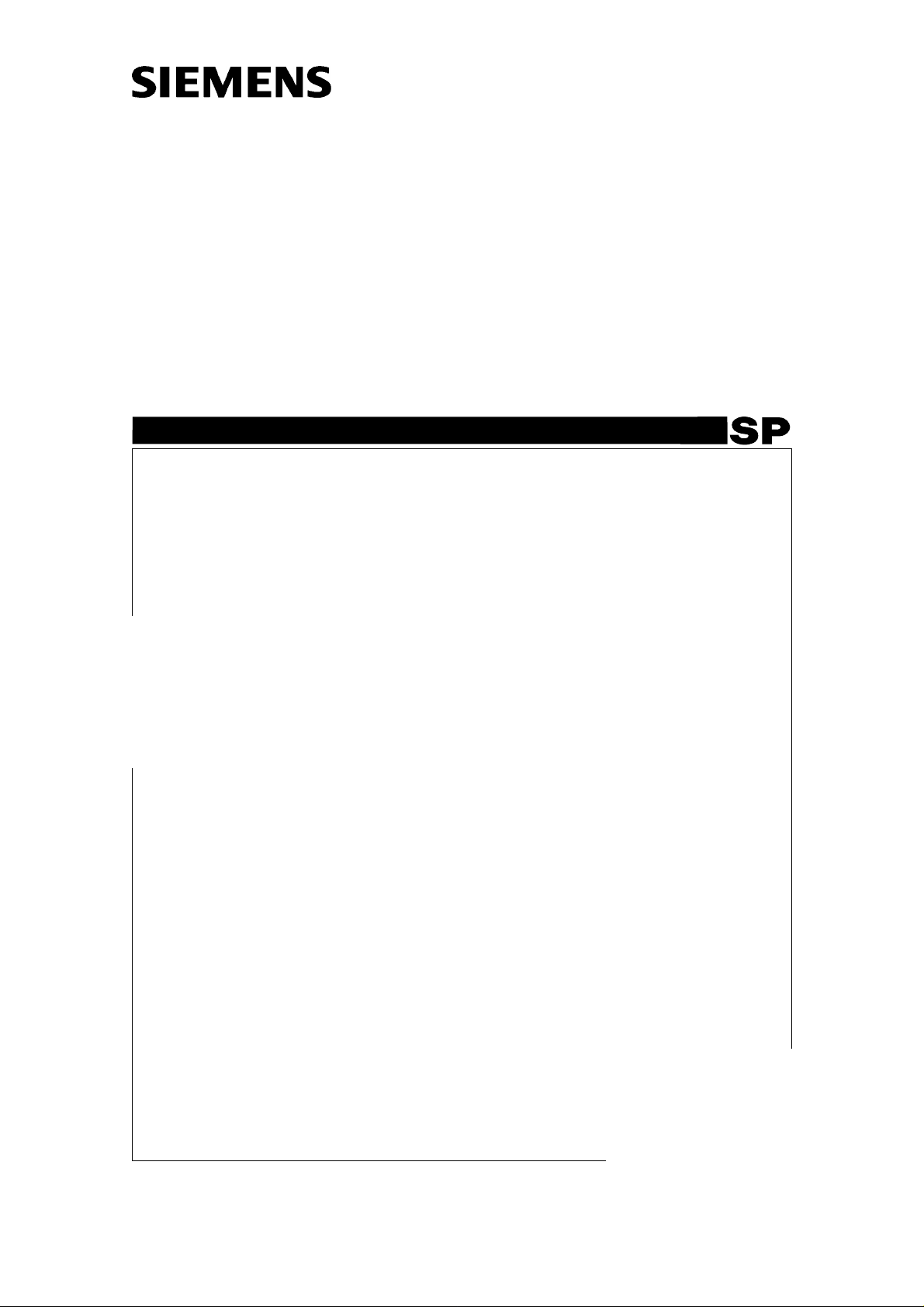
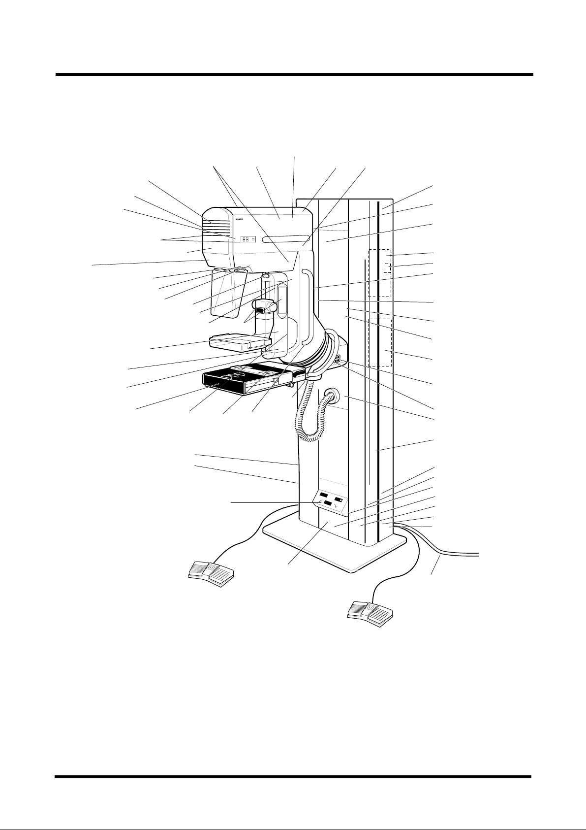
SYSTEM OVERVIEW
MAMMOMAT 1000 0
MAMMOMAT 1000
Fig. 1 Mammomat1000 with generator with integrated control panel a nd radiation shield.
MAMMOMAT
Siemens Elema AB Register 6 SP B7-230.051.05 Page 1 of 4 Mammomat 1000/3000
Solna, Sweden Rev . 02 10.99 SPS-UD Wiring Diagrams
Page 6
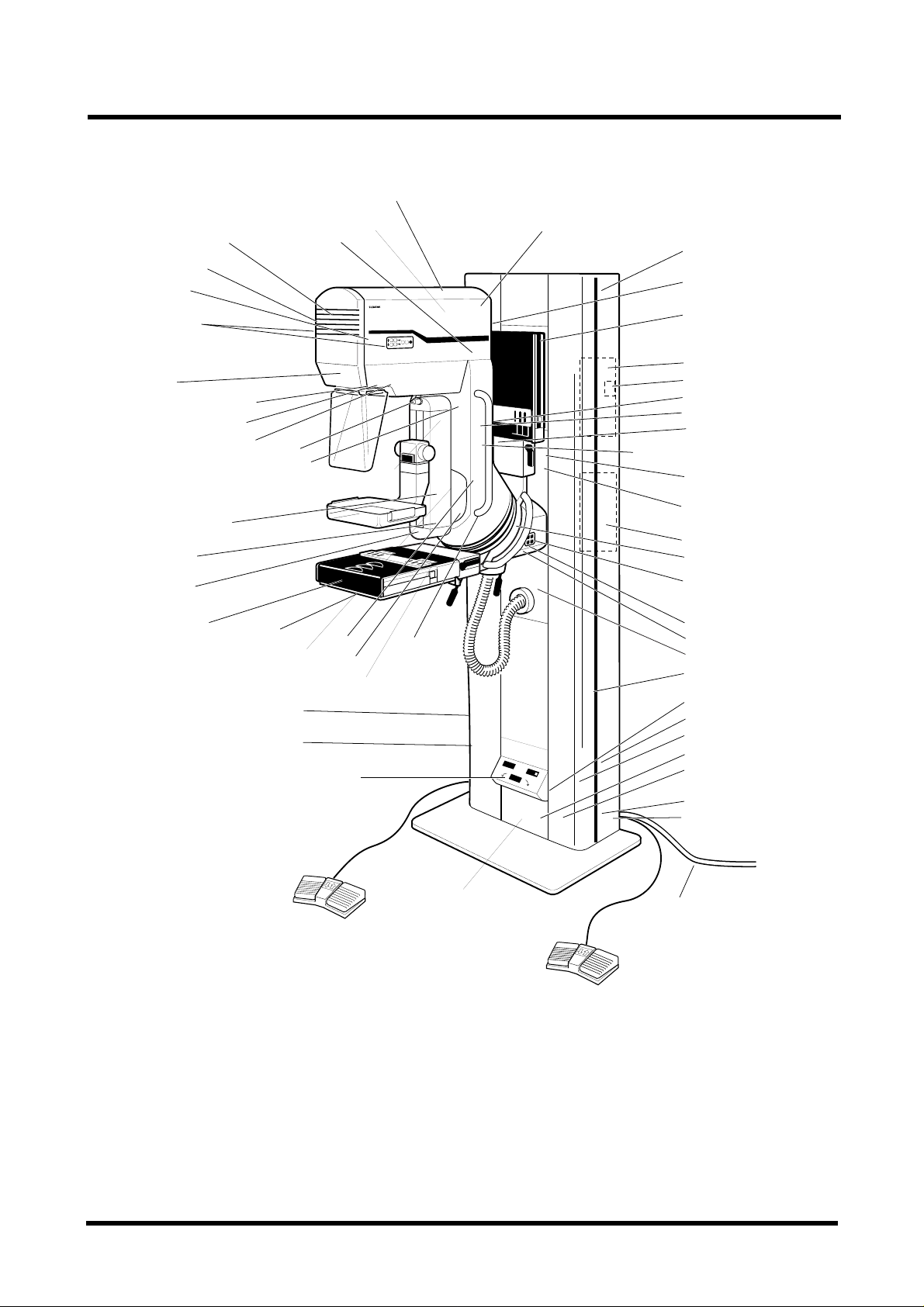
1-2 X041E
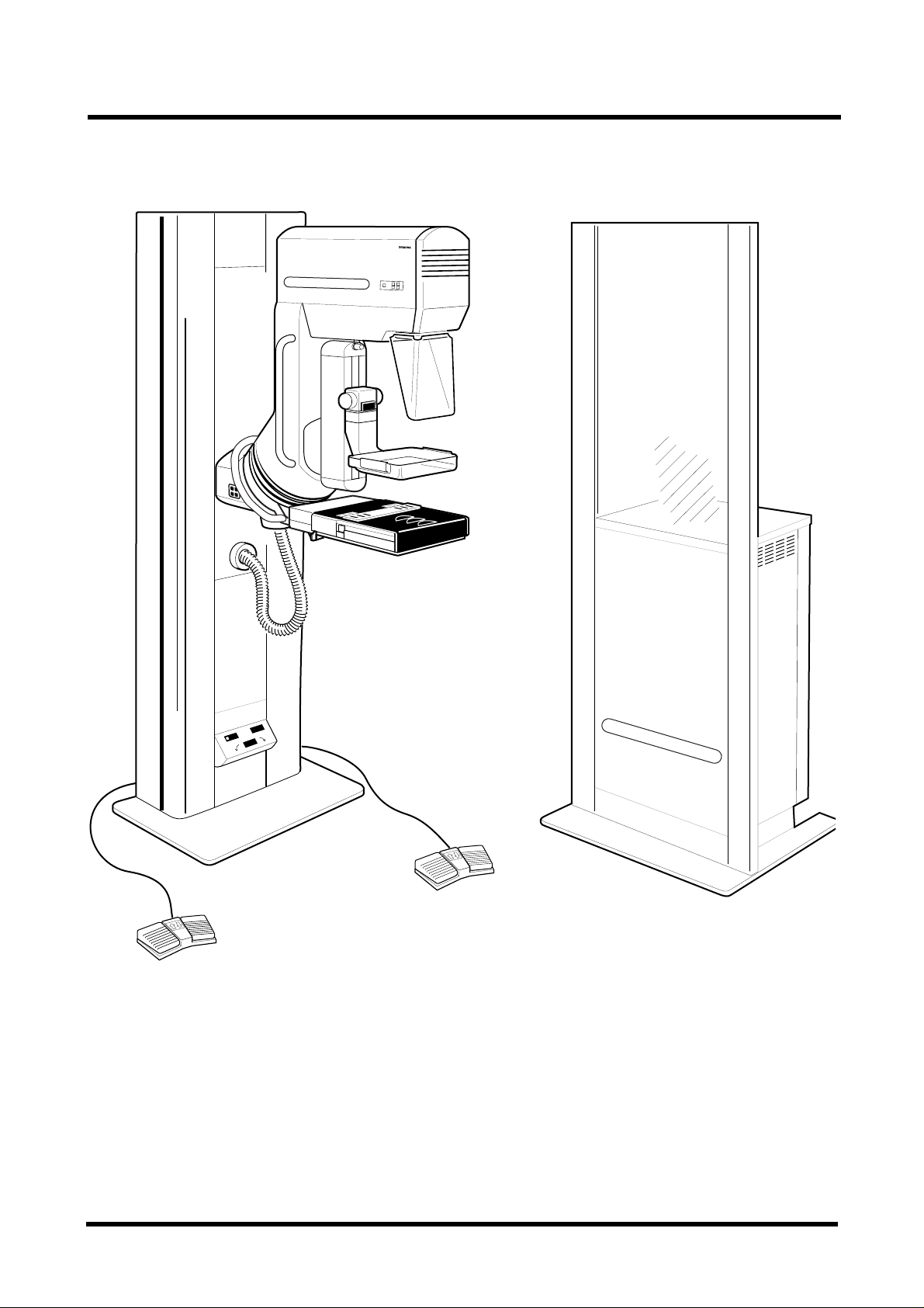
SYSTEM OVERVIEW 1
MAMMOMAT 1000 WITH REMOTE CONTROL 0
MAMMOMAT 1000
MAMMOMAT 1000
MAMMOMAT
MAMMOMAT
Fig. 2 Mammomat 1000 gene rat or with integrated control panel and ra diation shield .
MAM00638
MAM00638
Siemens Elema AB Register 6 SP B7-230.051.05 Page 2 of 4 Mammomat 1000/3000
Solna, Sweden Rev . 02 10.99 SPS-UD Wiring Diagrams
Page 7
X041E 1-3
SYSTEM OVERVIEW 1
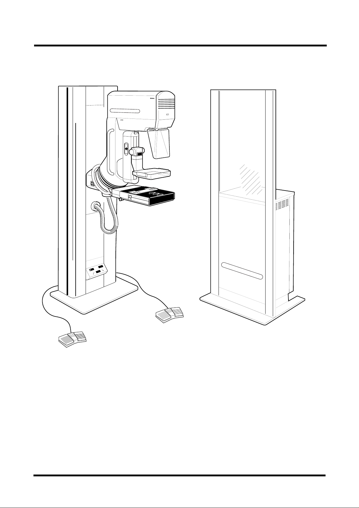
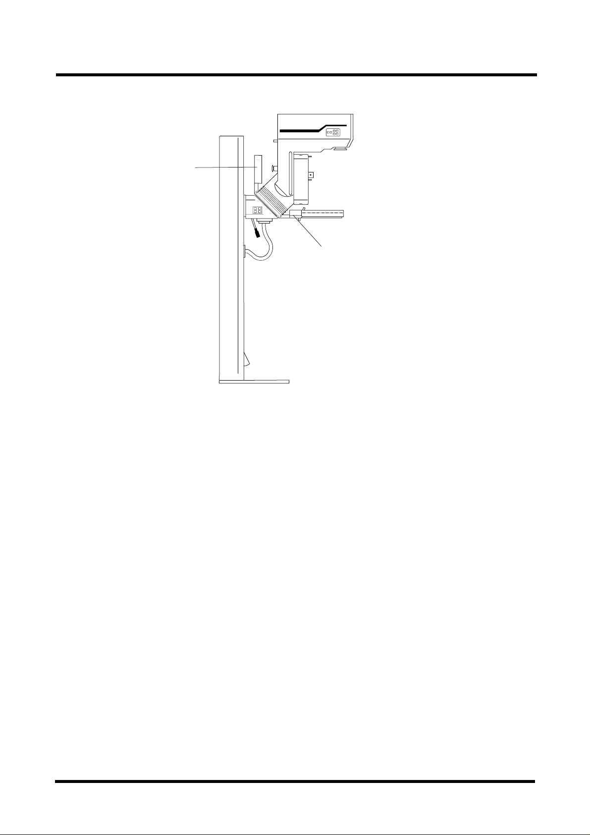
MAMMOMAT 3000 0
Fig. 3
MAMMOMAT 3000 in stallation with pivoted obje c t- ta ble arm and generator with integrated control panel and radiation shield.
Alternat iv ely, the contro l panel and the radiation shi eld can be sepa rat ed from the generator, see overle af .
Siemens Elema AB Register 6 SP B7-230.051.05 Page 3 of 4 Mammomat 1000/3000
Solna, Sweden Rev . 02 10.99 SPS-UD Wiring Diagrams
MAM00421
Page 8
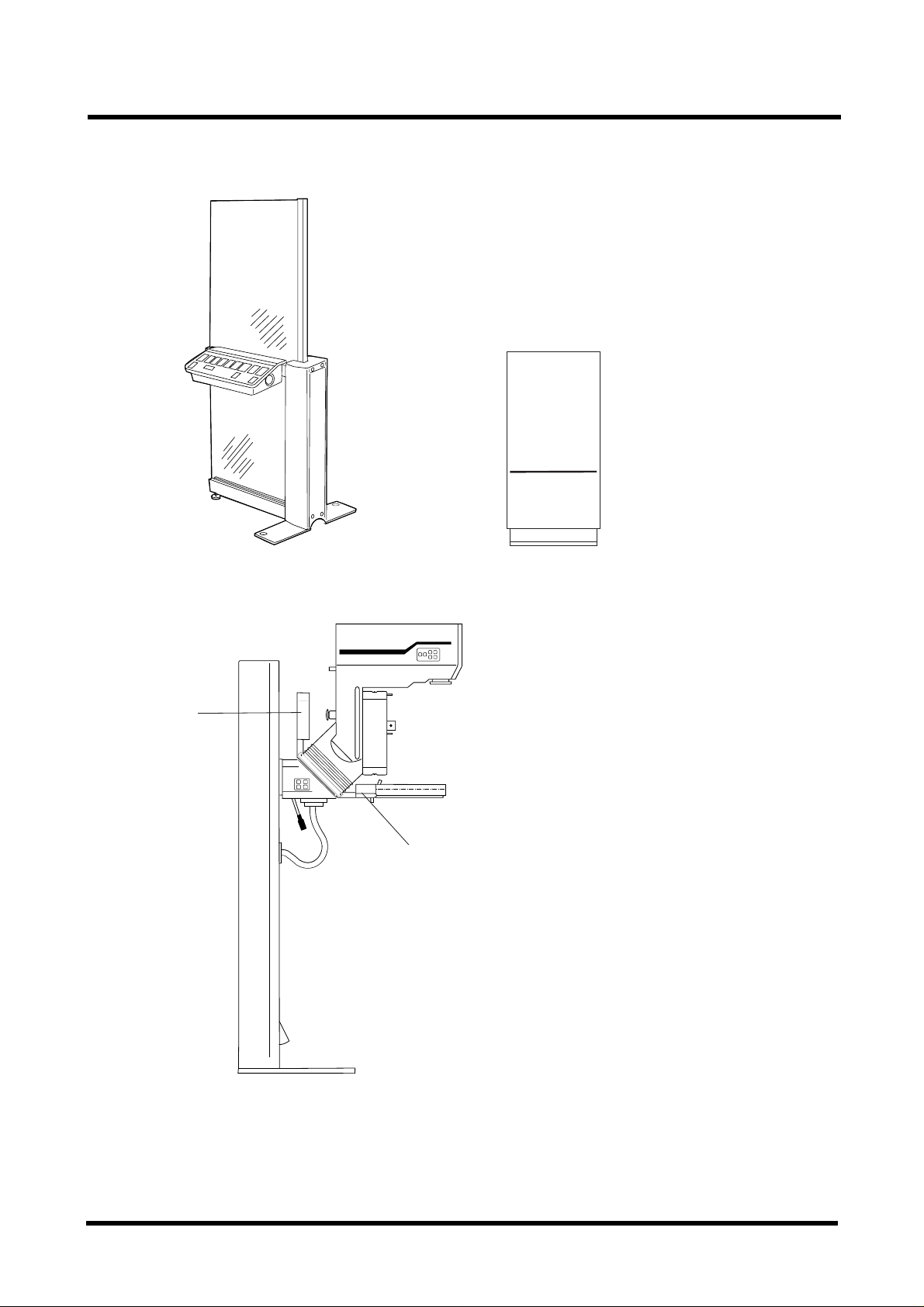
1-4 X041E
MAM00423
SYSTEM OVERVIEW 1
MAMMOMAT 1000/3000
SIEMENS
MAMMOMAT 3000
Counterweight
Fig. 4 Free-standing radiation shield with separate
contro le console
SIEMENS
·
Fixed object-table arm
MAM00424
Fig. 5 Separate generator
MAMMOMAT 3000
MAM00427
Fig. 6 Stand with fixed object-table arm
Pivoted object-table arm (“f ly ing wing”) replac ed by fixed objec t -t able arm and cou nt erweight.
Siemens Elema AB Register 6 SP B7-230.051.05 Page 4 of 4 Mammomat 1000/3000
Solna, Sweden Rev . 02 10.99 SPS-UD Wiring Diagrams
Page 9
X041E 2-1
PLACEMENT OF PC-BOARDS AND COMPONENTS, STAND
MAMMOMAT 1000 0
K7-K9
S867*
m5*
D807 Right side
D807 Left side
S865*
S866*
m4*
m7*
* not fitted with one
filter collimator
** not used with one
filter collimator
*** not used
Lamp, X894
M2 (Compression)
Strain gauge
D804
Object table
S1
S2
M
Tube
S897
S868*
m8*
D813****
R861
X874
S861
S862
S883
S884
D813****
R863
S892
X892
D803
X801
X877
X878**
D811****
X858***
X870
M6
MAMMOMAT 1000
D813****
Z801
D812****
D805
M1 (Lift), X887, R807
R871
S882
D801
D809
S880
S881
S869
M3 (Rotation)
X888
D802
D808 Right side
D808 Left side
R803
X898, R806
R805
X881
X885
X880, X803
T802
T801
X899
F801-805
MAM00637
Incoming mains
**** option, remote control
Fig. 7
Siemens Elema AB Register 6 SP B7-230.051.05 Page 1 of 16 Mammomat 1000/3000
Solna, Sweden Rev . 02 10.99 SPS-UD Wiring Diagrams
Page 10
2-2 X041E
PLACEMENT OF PC-BOARDS AND COMPONENTS, STAND
MAMMOMAT 3000 0
M6
K7-K9
S867, M5
D807 Right side
D807 Left side
S865
S866
Lamp, X894
M4
M7
Tube
S897
S868
m8
R861
X874
D805
X877
X878
R863
D810
M1 (Lift), X887, R807
R871
S882
D801
D809
S880
S896
S881
S892
X892
S869
M2 (Compression)
Strain gauge
D804
Object table
S1
S2
M
S890
S884
S861
S862
S883
S896
S895
S891
X891
D803
X801
X858
X870
Z801
M3 (Rotation)
X888
D802
S894
D808 Right side
D808 Left side
R803
S860
X898, R806
R805
X880, X803
X881
X885
T802
T801
X899
F801-805
MAM00426
Incoming mains
Fig. 8 Stand with pivoted object-table arm
Siemens Elema AB Register 6 SP B7-230.051.05 Page 2 of 16 Mammomat 1000/3000
Solna, Sweden Rev . 02 10.99 SPS-UD Wiring Diagrams
Page 11
X041E 2-3
PLACEMENT OF PC-BOARDS AND COMPONENTS, STAND
SIEMENS
·
Counterweight
Fixed object-table arm
MAM00427
Fig. 9 Stand with fixed object-table arm
Pivoted object-table aram (“flying w ing”) replaced by fixed objec t -t able arm and c ounterweigh t
Siemens Elema AB Register 6 SP B7-230.051.05 Page 3 of 16 Mammomat 1000/3000
Solna, Sweden Rev . 02 10.99 SPS-UD Wiring Diagrams
Page 12

2-4 X041E
LIST OF BOARDS AND FUSES, STAND
PCB Overview 0
D801 CPU BOARD
D802 MOT OR CONTROL BOARD
D803 DISPLAY BOARD
D804 FORCE AMPLIFIER BOARD
D805 WING BOARD
D807 BOARD FOR LIFT, ROTATION AND LAMP SWITCHES (NOT FIT-
TED IN M1000)
D808 BOARD FOR LIFT AND ROTA TION SWITCHES
D809 THICKNESS ADAPTER BOARD
D810 TILT SWITCH BOARD (Not fit ted i n M1000)
Option, remote control (MAMMOMAT 1000 only) 0
D81 1 REMOTE CONTROL TRANSMITTER (2 INCLUDED)
D812 REMOTE CONTROL RECEIVER (1 INCLUDED)
D833 REMOTE CONTROL DETECTOR (4 INCLUDED)
Fuses Overview 0
PCB FUSE FUSED VOLTAGE
D801 F1 2 AT +5V, +5V_REF, +5V_DSP, +7V
D801 F2 1 AT +5V_MPS
D802 F1 5 AT +5V, +5V_M, +14V, D805/+5V
D802 F2 3.15 AT +24VF, +15V
D802 F3 6.3 AT +24V
D802 F5 5AT 17VAC (LAMP)
D802
Chassis-mounted
fuses
F4 1 AT 24VACF (FAN)
F801 2 AT 11 VAC
F802 1 AT 11 V_M P S
F803 5 AT 14 VAC
F804 5 AT 17 VAC
F805 6.3 AT 24 VAC
NOTE! See spare parts list for replacement fuses.
Siemens Elema AB Register 6 SP B7-230.051.05 Page 4 of 16 Mammomat 1000/3000
Solna, Sweden Rev . 02 10.99 SPS-UD Wiring Diagrams
Page 13

X041E 2-5
LIST OF SWITCHES AND COMPONENTS, STAND
Switches 0
Switch Page Description
S1/D 801 3-6/1D Reset switch fo r st a n d C P U .
S1/Object table 3-16/2A Grid out switch located in the object tabl e.
S1-1-4/D802 3-9/3D Current li m it switches: 1=+3%, 2=+6 %, 3=+12% , 4=+24%.
S1-5/D802 3-9/3D Tacho On/Off switch for rotation motor drive.
S1-S6/D807* 3-10/2A Control switches for lamp, lift- and r otation movement. Left and right side.
S1-S6/D811**** Control swithces and transmitter fo r la mp , lift- and rotation move ment.
Left and right side. 2 provided.
S1-S4/D808 3-10/4B Control switches for lift- and rotat ion movement. Left and right side.
S2/Object table 3-16/2A Cassette inserted switch.
S860* 3-16/3C Stereo lever switch
S861 3-12/2G Compression limit switch, compression unit.
S862 3-12/2G Decompression limit switch, compression unit.
S865** 3-15/2E 18 x 24 Collimator optoswitch
S866** 3-15/3E 24 x 30 Collimator optoswitch**.
S867** 3-15/4E Filter position, optoswitch**.
S868** 3-15/5E Focus position optoswitch**.
S869 3-8/3G Tacho opt oswitch
S880 3-4/2B Emergency stop, switches off 24VAC and 14VAC, machine blocked.
S881 3-9/2G Lift up limit switch, rotating unit.
S882 3-4/2A Limit switch, dista nce tube head - floor <50 mm, switch es off 24VAC,
machine blocked.
S883 3-8/4B Collision protection switch, risk of collision when tubehead is less than
120 mm from the floor.
S884 3-9/2G Lift down limit switch, rotating unit.
S890* 3-16/3C AEC in position switch (Wing 1)
S891* 3-16/3C Object table locked in position (Wing1)*.
S892 3-16/2C Object table locked in posi tion (Wing 2)***.
S894* 3-16/3C Select wing 1 switch*, ***.
S895* 3-16/3C Select wing 2 switch*, ***.
S896* 3-13/5B Tilt opto-switch. 0° or ±10
S897 3-15/2G Diaphr agm swit ch.
S3 3-12/5F Decompression button (only with separate control console)
*.
**.
*.
0
used with stereo option*.
.
* Not fitted in M1000
** Not fitted in M1000 with one filter
*** Not fitted in M3000 one wing
**** M1000 option, remote control
Siemens Elema AB Register 6 SP B7-230.051.05 Page 5 of 16 Mammomat 1000/3000
Solna, Sweden Rev . 02 10.99 SPS-UD Wiring Diagrams
Page 14
2-6 X041E
LIST OF SWITCHES AND COMPONENTS, STAND
Potentiometers 0
Potentiometer Page Description
R803 3-13/2A Tube angle, 2k.
R861 3-11/3E Preset force, 10k.
R863 3-11/3E Thickness, 2k.
R871 3-13/2A Preset angle, 10k.
Motors 0
Motor Page Description
M 3-16/2A Grid motor, pl aced in object table with gri d.
M1 3-9/2G Lift motor.
M2 3-12/2G Compression motor.
M3 3-9/ 3G Ro tation motor.
M4* 3-15/3D Collimator stepping motor
M5* 3-15/4D Filter st epping motor
M6 3-7/4E Fan, tube cooling.
M7* 3-14/4G Mirror magnet
M8* 3-15/5D Focus stepping motor
M9 3-9/ 5G Ro tat ion brake.
M10 3-9/5G Rotation brake.
*.
*.
*.
*.
* Not fitted in M1000 with one fil ter
Miscellaneo us 0
Misc. Page Description
COMP. UNIT 3-11, 3-12 Compression unit.
CABLE DUCT 3-2/3A Generator to stand cable protecti on.
GROUND RAIL 3-2/1E System grounding terminal.
K7 3-7/4E Fan thermost at.
K8 3-7/4E Tube overtemperature t herm ostat.
K9 3-7/4E Tube housing overpressure switch.
L804 - L809 3-9/SG
3-12/2G
LAMP 3-14/5G F iel d light lamp.
R805 3-9/5G Brake resistor, 6.2Ω.
R806 3-9/5G Brake varistor
R807 3-9/2G Lift motor varistor.
R860 3-11/2A Strain gauge (R=300-400 Ω)
T801 3-3/2C Mains transformer.
T802 3-3/3C Insolation transformer
Z801 3-3/4C Stereo mains filter, stand
C801 - C803 3-12/5G EMC capacitors
VHF choke (EMC)
Siemens Elema AB Register 6 SP B7-230.051.05 Page 6 of 16 Mammomat 1000/3000
Solna, Sweden Rev . 02 10.99 SPS-UD Wiring Diagrams
Page 15

X041E 2-7
LIST OF SIGNALS AND TEST POINTS, STAND
This page int entionally le ft blank.
Siemens Elema AB Register 6 SP B7-230.051.05 Page 7 of 16 Mammomat 1000/3000
Solna, Sweden Rev . 02 10.99 SPS-UD Wiring Diagrams
Page 16

2-8 X041E
LIST OF SIGNALS AND TEST POI NTS,STAND
Page Signal Name Origin Via Destination Testpoint LED
3-9/1C ACT_SPEED TACHO D802 ACT_SPEED
3-16/3C AEC_POS S890 D801 D801
3-10/2A ANGLE_MEM A.M. -pot D807 D801
3-6/2B AR VH D801 GENERATOR D801 AR
3-11/3B BR_OPEN D804 D804.X843 pin 8 V2
3-11/3B BR_RET D804 D804.X843 Pin 7
3-9/4B
3-9/4E
3-9/4E
3-15/3C C_LA D805 M4
3-15/3C C_LB D805 M4
3-9/4E C_LIM D802 V11
3-15/3C
3-15/3C
3-15/3C
3-15/3C
3-12/2D C_PWM D802 M2 D802
3-16/1A CASS_LOADED OBJ. TABLE D805 D801
3-16/2C
3-16/2C
3-16/3E COLL_POS_18X24 18x24 switch D805 D801 COLL_P1
3-16/4E COLL_POS_24X30 24x30 switch D805 D801 COLL_P2
3-12/1E COMP_LIMIT D802 D805 COMP. UNIT
3-12/1B
3-11/2F COMP_FORCE D804 D801 D804.X843 pin 5
3-12/3E COMP_OK D802 D801 D802 V2
3-12/1E COMP_PROT D802 D801 D802
3-12/1B
3-12/4F COMPRESS PEDAL D805 D801, D802
3-9/2D D_PWM D802 D802
3-12/1E DECOMP_ LIMIT D802 D805 COMP. UNIT
3-12/4F DECOMPRESS PEDAL / ** D801
3-9/3B
3-9/4F DRIVE_OK D802 D801 D802
3-9/1E DRIVE_PROT D802 D801 D802
3-15/3D FI_LA D805 M5
3-15/3D FI_LB D805 M5
3-15/3D
“*SIGNAL” = “SIGNAL” active low
**plus decomp ression button on sepa rate control console.
BRAKE D801 D802
*
BRAKE_RET D802 M9, M10 D802
*
BRAKE_RELAY D802 not used
*
C_PA1 D805 M4
*
C_PA2 D805 M4
*
C_PB1 D805 M4
*
C_PB2 D805 M4
*
COLL_DIR D801 D805 D805 COLL_D
*
COLL_STEP D801 D805 D801, D805 COLL_ST
*
COMP_DIR D801 D802 D802 COMP_D
*
COMP_SPEED D801 D802 D801, D802
*
DIR D801 D802 D802
*
FI_PA1 D805 M5
*
COMP_SP
COMP_ERR
V24DRIVE_ERR
Siemens Elema AB Register 6 SP B7-230.051.05 Page 8 of 16 Mammomat 1000/3000
Solna, Sweden Rev . 02 10.99 SPS-UD Wiring Diagrams
Page 17

X041E 2-9
LIST OF SIGNALS AND TEST POINTS, STAND
Signal Name Description
ACT_SPEED Test point for frequency to volt age converted tacho signal .
AEC_POS AEC-detector in position near breast.
ANGLE_MEM Operator control signal for preset stop angle.
AR Signal given to generator as exposure request. If grid used, grid has started.
BR_OPEN Bridge open, compression force stra in gauge not working correctly .
BR_RET Compression force strain guage retur n li ne (appr . 0V)
*BRAKE Control signal to brake reversing relay.
*BRAKE_RET Output to the brakes for max or min braking when active.
BRAKE RELAY Output to brake reversing relay, max brake if *BRAKE_RET active.
*
C_LA Output li ne A. Col li m ator stepping motor M4
C_LB Output li ne B. Col li m ator stepping motor M4
C_LIM Rotation and fast-acting current limit
C_PA1 Output Phase A1. Collimator stepping motor M4
*
C_PA2 Output Phase A2. Collimator stepping motor M4
*
C_PB1 Output Phase B1. Collimator stepping motor M4
*
C_PB2 Output Phase B2. Collimator stepping motor M4
*
C_PWM Pulse Width Modulated power output to compression motor.
CASS_LOADED Cassette inserte d in obj ect table.
COLL_DIR Directi on Control signal . For the fi lter stepping motor.
*
COLL_STEP Step control signal for the collimator ste pp in g m o to r.
*
COLL_POS_18X24 Signal from the 18 x 24 colli m ator optoswitch
COLL_POS_24X30 Signal from the 24 x 30 colli m ator optoswitch
COMP Power output via compression limit switch to compression motor.
COMP_DIR Controls compression motor to compress (mo ving down)
*
COMP_FORCE Analog signal indicating compression force.
COMP_OK Compression motor working correctly, no over current.
COMP_PROT Compression relay K4 is working correctly, checked 1s after pedal release.
COMP_SPEED Pulse Width Modulated signal to control speed of compression motor (20kHz) .
*
COMPRESS Operator control signal to move compression plate down.
D_PWM Pulse Width Modulated power output to r otation or lift motor.
DECOMP Power output via decompression limit switch to compression motor.
DECOMPRESS Operator control signal to move compression plate up.
DIR Selecting direct ion of rotation or lift motor.
*
DRIVE_OK Rotation and lift motor are working corr ectly, no over current, approx. 1.5 s delay.
DRIVE_PROT DMG relay K6 is working correctl y, checked 3s after rot/l if t button is released.
FI_LA Output line A. Filter stepping motor M5
FI_LB Output line B. Filter stepping motor M5
FI_P A1 Output phase A1. Filter steppi ng mo tor M5
*
Siemens Elema AB Register 6 SP B7-230.051.05 Page 9 of 16 Mammomat 1000/3000
Solna, Sweden Rev . 02 10.99 SPS-UD Wiring Diagrams
Page 18

2-10 X041E
LIST OF SIGNALS AND TEST POINTS, STAND
Page Signal Name Origin Via Destination Testpoint LED
3-15/4C
3-15/4C
3-15/4C
3-15/2C
3-15/2B FILTER_POS Filter switch D805 D801 FILT_P
3-15/2C
3-15/5C FO_LA D805 M8
3-15/5C FO_LB D805 M8
3-15/5C
3-15/5C
3-15/5C
3-15/5C
3-15/1C
3-15/1B FOCUS_POS Focus switch D805 D801 FOCUS_P
3-15/1C
3-16/3B GRID_MOTOR_N D802 D805 OBJ. TABLE D802 GRID_M
3-16/2A GRID_OUT OBJ. TABLE D805 D801 D801 GRID_O
3-16/2G
3-1 1/3D I1_OUT D804 D804.X843 pin 6
3-6/2B
3-14/5G LAMP D807, D812** D805 D801
3-14/4C
3-14/5F LAMP_V D802 LAMP D802 LAMP
3-8/3D LED D802 TACHO switch
3-15/2E LED_1 D805 18 x 24 switch
3-15/3E LED_2 D805 24 x 30 switch
3-15/4E LED_3 D805 Filter switch
3-15/5E LED_4 D805 Focus switch
3-10/2A LIFT_DOWN D807, D808, D812** D805 D801, D802
3-10/2A LIFT_UP D807, D808, D812** D805 D801, D802
3-14/4F
3-6/3B MPS D801 GENERATOR D801
3-7/4C OKT1_ TUBE/K8 GENERATOR
3-7/4C OKT2_ TUBE/K9 GENERATOR
3-9/2C PGM_SPEED D802 PGM_SPEED
3-13/2D POT_RETURN POT D801
3-11/2E PRES_FORCE R861 D801
3-13/1A PRESET_ANGLE R871 D805 D801
FI_PA2 D805 M5
*
FI_PB1 D805 M5
*
FI_PB2 D805 M5
*
FILTER_DIR D801 D805 D805 FILT_D
*
FILTER_STEP D801 D805 D805 FILT_ST
*
FO_PA1 D805 M8
*
FO_PA2 D805 M8
*
FO_PB1 D805 M8
*
FO_PB2 D805 M8
*
FOCUS_DIR D801 D805 D805 FOCUS_D
*
FOCUS_STEP D801 D805 D805 FOCUS_DT
*
GRID_SPEED D801 D802 D801 GRID_SP
*
KVA D801,D701
*
LAMP_CTRL D801 D802
*
MIRROR_MAGNET D802 M7 D802 MIRROR
*
D702, D705
D700 (GENERATOR) D801 (D705, X715)
“*SIGNAL” = “SIGNAL” acti ve low * * M1 000 option, remote contr ol, D807 not fitted
Siemens Elema AB Register 6 SP B7-230.051.05 Page 10 of 16 Mammomat 1000/3000
Solna, Sweden Rev . 02 10.99 SPS-UD Wiring Diagrams
Page 19

X041E 2-11
LIST OF SIGNALS AND TEST POINTS, STAND
Signal Name Description
FI_PA2 Output phase A2. Filter steppi ng m otor M5
*
FI_PB1 Output phase B1. Filter stepping m otor M5
*
FI_PB2 Output phase B2. Filter stepping m otor M5
*
FILTER_DIR Control signal . For the filter stepping motor.
*
FILTER_POS Signal from the filter pos collimator optoswitch
FILTER_STEP Step control. For the filter stepping motor.
*
FO_LA Output line A. Focus ste pping motor M8
FO_LB Output line B. Focus ste pping motor M8
FO_PA1 Output Phase A1. Focus stepping motor M8
*
FO_PA2 Output Phase A2. Focus stepping motor M8
*
FO_PB1 Output Phase B1. Focus stepping motor M8
*
FO_PB2 Output Phase B2. Focus stepping motor M8
*
FOCUS_DIR Control sign al f or the focus stepping motor.
*
FOCUS_POS Signal from the focus pos collimator optoswitc h.
FOCUS_STEP Step contr ol si gnal for the focus step ping motor .
*
GRID_MOTOR_N Grid motor return line.
GRID_OUT Active when the grid is not in end position.
GRID_SPEED Pulse Width Modulated si gnal control speed of grid motor.
*
I1_OUT Output signal from compress ion force preamplifier.
KVA Signal to terminate exposure. WIRED-OR line, see generator.
*
LAMP Operator control signal for the field light lamp.
LAMP_CTRL Signal to switch on the field light lamp.
*
LAMP_V Output to the field light lamp.
LED Output to the LED in the tacho opto switch in the rotation motor.
LED_1 Output to the LED in the 18 x 24 collimator opto switch.
LED_2 Output to the LED in the 24 x 30 collimator opto switch.
LED_3 Output to the LED in the filter collimator opto swi tch.
LED_4 Output to the LED in the focus collimator opto switch.
LIFT_DOWN Operator control signal to move compression plate down.
LIFT_UP Operator control signal to move compression plate up.
MIRROR_MAGNET Output to mirror magnet. Enabled via *LAMP_CTRL.
*
MPS Multi processor ser ial communication for information exchange Master - Slaves.
OKT1_ Signal from temperat ure switch K8 on the tube.
OKT2_ Signal from the over pr essure switch K9 on the tube.
PGM_SPEED T est point for duty cycle to vol tage converted programmed speed signal.
POT_RETURN Return line for potentiometers connected to 0VA via a 20Ω resistor.
PRES_FORCE Analog signal as preset value for maximum compression force.
PRESET_ANGLE Analog signal as preset value for requested rotation angle.
Siemens Elema AB Register 6 SP B7-230.051.05 Page 1 1 of 16 Mammomat 1000/3000
Solna, Sweden Rev . 02 10.99 SPS-UD Wiring Diagrams
Page 20

2-12 X041E
LIST OF VOLTAGES AND TEST POINTS , STAND
Page Signal Name Origin Via Destinati on Testpoint LED
3-12/2D PU D802 PU
3-9/4B
3-6/1E
3-6/1E
3-6/1E RESET_SW D801
3-10/3A ROT_CW D807, D808,
3-10/3A ROT_CCW D807, D808,
3-13/4A ROT_POS** D806** D801
3-6/3D RXD GEN. D801 D801
3-9/3B
3-16/3C SELECT_WING1 S891 D801
3-16/4C SELECT_WING2 S892 D801
3-9/2B
3-15/2C
3-15/1B STEREO_COLL S897 D801
3-16 STEREO_LEVER S860 D805 D801
3-14/1B TABLE_CONFIG OBJ.TABLE D805 D801
3-8/3G TACHO Tacho switch D802 D802 TACHO
3-11/3E THICKNESS R863 D801
3-11/5E THICKNESS_B THICKNESS D809
3-11/5F THICKNESS_STE-
3-13/5B TILT S896/D810 D80 5 D801 D810 V8
3-13/2A TUBE_ANGLE R803 D801
3-6/4D TXD D801 GENERATOR D801 TXD
3-6/3B VH GEN. D801
3-11/3C ZERO D804 D804.X843 pin 4
RELEASE D801 D802 D802
*
RESET D801
*
RESET_HW D801
*
D805 D801, D802
D812***
D805 D801, D802
D812***
SEL_ROT D801 D802 D802 SEL_ROT
*
SPEED D801 D802 D801, D802 SPEED
*
STEP_ENABLE D801 D805 D805 STEP_EN
*
D809 X885
REO
“*SIGNAL” = “SIGNAL” active low.
** Not used with software v2.1 or higher.
*** M1000 option, remote control, D807 not fitted
Siemens Elema AB Register 6 SP B7-230.051.05 Page 12 of 16 Mammomat 1000/3000
Solna, Sweden Rev . 02 10.99 SPS-UD Wiring Diagrams
Page 21

X041E 2-13
LIST OF VOLTAGES AND TEST POINTS, STAND
Signal Name Description
PU Pull up signal for er ror comparators = +15V, +5V, +24V voltages OK.
RELEASE Control signal to release the brakes from min or max to permanent magnet braking.
*
RESET Reset signal to the CPU.
RESET_HW Reset signal from the CPU to the reset cicuit, caused by slave restart and CPU watchdog
reset.
RESET_SW Signal from the reset switch to the CPU via the reset circuit.
ROT_CW Operator control signal to rot ate the x-ray system clockwise.
ROT_CCW Operator control signal to rotate t he x-ray system cou nter clockwise.
ROT_POS Low level signal pulse indicating +10 or -10 degrees of rotati on.
RXD Input for receiving data via MPS.
SEL_ROT Low level signal selects the rotation drive to be controlled.
*
SELECT_WING1 Signal from select wing 1 switch. Wing 1 selected.
SELECT_WING2 Signal from select wing 2 switch. Wing 2 selected.
SPEED Pulse Width Modulated signal to control speed of rotation or l ift motor (20 kHz).
*
STEP_ENABLE Control signal to ena ble all stepping motors.
*
STEREO_COLL External diaphragm switch, diaphragm in place. For stereo or spot diaphragm, 18 x 24
collimator in M1000 with one filter.
STEREO_LEVER Signal from stereo lever switch, indicating lever not in stereo position.
TABL E_CO NFIG 4 inputs from object table, see table configuration .
TACHO Signal from rotation motor tachometer.
THICKNESS Analog signal indicating the compression thickness.
THICKNESS_B Buffer ed output to the thicknes s adapter board D809 (Stereo opt ion)
THICKNESS_STE-REO Isolated anal og signal indicating compression thickness for stereo evaluation unit.
TILT Indicates that the stereo angl e is 0° or ±10°. Visible through vent opening behind tube.
TUBE ANGLE Analog signal indicating the rot ation angle.
TXD Output for sending data via MPS.
VH The stand is informed that the generator has completed its preparation.
ZERO Used for adjusting offset of the compression force amplifiers.
Siemens Elema AB Register 6 SP B7-230.051.05 Page 13 of 16 Mammomat 1000/3000
Solna, Sweden Rev . 02 10.99 SPS-UD Wiring Diagrams
Page 22

2-14 X041E
LIST OF VOLTAGES AND TEST POINTS , STAND
Page Voltage Origin Supplied from Supply for T est LED Fuse
3-3/4E +5V D801 11V Di gital IC,
+5V_REF
3-3/4E
3-1 1/3B
3-3/3E +5V_DSP D801 11V D803, Display 5V_DSP V6 D801/F1 F801
3-3/2E
3-10/3B
3-3/3E +5V_MPS D801 11V_MPS Generato r
3-3/3D 0VD GND D801/X811 Digital IC 0VD1,OVD2
3-3/3D
3-10/3B
3-6/5D 0V_MPS D700/GND Generator inter-
3-3/2C 11V T801 230VAC +5V, +5V_DSP,
3-6/5B 1 1V_MPS T801 230V AC +5V_MPS D801/F2 F802
3-4/3D +5V D802 14VAC Digital IC 5V V57 D802/F1 F803
3-4/4E +5V_M D802 +5V D801-D802
3-2/5C 0V_W D801 D805/X856 Optointerface
3-2/4C 0V_M D801 D80 2/X822 Optoi nterface
3-4/3D +14V D802 14VAC +5V, D805 14V D802/F1 F803
3-4/2D +15V D802 +24VF Transistor
3-4/2C +24V D802 24VAC +15V D802/F3 F805
3-4/2D +24VF D802 +24V Switches,
3-4/3A 14VAC T801 230V AC +14V D802/F1 F803
3-14/5B 17VAC T801 230VAC LAMP 17VACF D802/F5 F804
3-14/4E 17VACF D802 17VAC LAMP 17VAC_RET D802/F5 F80 4
3-14/4D 0V_L D802 D802 Lamp control
3-14/5D -V_L D802 17VACF Lamp control
3-4/2A 24VAC T801 230V AC D802/F3 F805
3-4/2E 24VACF D802 24VAC Fan D802/F4
3-4/3B 0V GND D802/X821 Ground 0V, 0V1
3-4/2F +5V D805 D802/+14V Di gital IC 5V V17 D802/F1 F803
3-4/2G +5V_R D805 +5V User switches D802/F1 F803
+5V_REF D801 +5V Pots.
D804
+7V D801 11V Analog IC,
D804
interface
0V A 0VD D801 Analog IC
D804
face ground
+7V
opto interface
drivers M1,M3
relays, etc
5V V7 D801/F1 F801
5V_REF
X843 pin 2
7V
X843 pin1
5V_MPS V26 D801/F2 F802
0V A1
X843 pin 3
D801 MPS
15V V16 D802/F2
24VF D802/F2
V5 D801/F1 F801
V57 D802/F1 F803
D801/F1 F801
D801/F1 F801
Siemens Elema AB Register 6 SP B7-230.051.05 Page 14 of 16 Mammomat 1000/3000
Solna, Sweden Rev . 02 10.99 SPS-UD Wiring Diagrams
Page 23

X041E 2-15
LIST OF VOLTAGES AND TEST POINTS, STAND
Voltage Description ( typical value)
+5V Regulated DC voltage, 4.75V < +5V < 5.25V
+5V_REF DC voltage, +5V -5% < +5V_REF < +5V
+5V_DSP Regulated DC voltage, 4.75V < +5V_DSP < 5.25V
+7V Regulated DC voltage, 6.60V<+7V<7.25V
+5V_MPS Regulated DC voltage, 4.75V < +5V_MPS < 5.25V
0VD Digital ground
0VA Analog ground
0V_MPS Generator interface ground. Floating, grounded by generator.
1 1V AC supply voltage, 11VAC
1 1V_M P S AC supply voltag e, 11VAC
+5V Regulated DC voltage, 4.75V < +5V < 5.25V
+5V_M Regulated DC voltage, 4.75V < +5V_M < 5.25V for optointerface D801-D805
0V_W Digital ground optointerface D801 - D805
0V_M Digital ground optointerface D801 - D802
+14V Unregulated DC voltage, 18V
+15V Regulated DC voltage, 14.25 V < +15V < 15.75V
+24V Unregulated DC voltage, 32V
+24VF Unregulated DC volta ge, 32V
14V AC AC supply voltage, 14 VAC
17VAC AC supply voltage, 17 VAC
17VACF AC supply for lamp
0V_L Floating ground for LAMP voltage regulation
-V_L Unregulated supply voltage for lamp control circuit
24VAC AC supply voltage, 24VAC
24VACF AC supply voltage for the fan 1)
0V Circuit ground
+5V Regulated DC voltage, 4.75V < +5V < 5.25V
+5V_R Regulated DC voltage, 4.40V < +5V_R < 5.2 5V
1) 2)
1) 2)
1)
1)
1)
1) 2)
1) 2)
1)2)
1)2)
1)2)
1) 2)
2)
Siemens Elema AB Register 6 SP B7-230.051.05 Page 15 of 16 Mammomat 1000/3000
Solna, Sweden Rev . 02 10.99 SPS-UD Wiring Diagrams
Page 24

2-16 X041E
LIST OF VOLTAGES AND TEST POINTS , STAND
Page Voltage Origin Supplied
from
3-3/2B 230VAC Generator D711/X14 Stand X881/2,3
3-3/1C P.E. Stand X899 Inc. ma ins voltage Whole syst em X899/PE
3-3/1C N Stand X899 Inc. mains voltage Whole system X899/N
3-3/1C L1 Stand X899 Inc. mains voltage Whole syst em X899/L1
3-3/1C L2 Stand X899 Inc. mains voltage Whole syst em X899/L2
3-3/1C L3 Stand X899 Not used X899/L3
1)
ST ANDBY TYPICAL VALUE, 230VAC INPUT
2)
Floating voltage. Measure with digital multimeter or differential amplifier.
Vol tage Description ( typical value)
230V AC Stand mains volta ge input, 207VAC < 230VAC < 253VAC
P.E. Protective earth terminal, incoming mains
N Neutral line terminal, incoming mains
L1 Line 1 terminal, incoming mains voltage
L2 Line 2 terminal, incoming mains voltage
L3 Not used
Supply for Test LED Fuse
Siemens Elema AB Register 6 SP B7-230.051.05 Page 16 of 16 Mammomat 1000/3000
Solna, Sweden Rev . 02 10.99 SPS-UD Wiring Diagrams
Page 25

X041E 3-1
BLOCK DIAGRAM CABLE CONNECTIONS
123
FILTER
FOCUS
M8
COLLIMATOR
X879
X890
OBJECT TABLE 2
OBJECT TABLE 1
T. IN POS
TABLE BASE 1 OBJECT TABLE 1
MIRROR
18X24
24X30
M7
M4
SPOT
STEREO
LAMP
X854
X852
X877
X853
X894
PRESET
M5
X866
X867
X878
M1
M
CASS IN PLACE
GRID OUT
GRID
X887
D804
COMPRESSION
M6
FAN LIFT
SET WING 1
AEC IN_POS
STEREO
TUBE TEMP, PR ESS URE
X895
X895
COMPRESSION
4
5
D810
D806*
ANGLE
DETECTOR
TILT
STEREO LE VER
TACHO
BRAKE
ROTATION
ROTATI O N
X868
X888
X874
FORCE
COMPRESSION
FORCE
X868
X841 X861
M9, M10
X824
X823
X826
* D806 no t used with s oftware v2.1 or higher.
**REMOTE CONTROL OPTION
F
M2 M3
D803
X891
X892
X883
X884
X3**
X808
X807
USER INTERFACE
COMP
DECOMP
ROT CW
ROT CCW
LIFT UP
X893
X823
X824
X851
X857
X859
X865
X869
X871
X864*
X856
X863
X868
+5V_R
D805
WING BOARD
X858
LIFT DOWN
LAMP
ANGLE MEM
X870
X889
X855
X856
X860
X824
+5V +/4V
D802
MOTOR CONTROL
X825
X822
X823
X824
DISPLAY
X801
X821
17V AC
+24V +15V
+14V +5V
X1**
X809
X812
X813
X814
230 VAC
Tostereo
D809
Z801
80C535
T802
X802
STAND
X885
Stereo ( option)
D801
CPU BOARD
X813
X814
X816
INCOMING MAINS
110, 208, 230, 240, 277 OR 400V
X811
+7V +5V
X886
+5V_MP
X886
SINGLE OR TWO PHASE
X899
T801
230V FROM GENERATOR
X886
ABCDEFG
GENERATOR
X10
X11
.
GEN
X1 X815
Siemens-Elema AB SP B7-230.051.05 Page 1 of 18 Mammoma t 1000/3000
Solna Sweden Rev . 02 10.99 SPS-UD Wiring Diagram
Page 26

3-2
GROUNDING CONNECTION S
X041E
123
FRONT
COVER
REAR
H3
X896
FILAMENT
PATIENT
HANDLE
TUBE
PLATE
TUBE
CHASSIS
PATIENT
HANDLE
COMPRESSION
UNIT
COVER
X897
ROTATION
X870
GROUND RAIL
CURTAIN
UPPER
LIFT
CARRIAGE
LOWER
STAND
0V
INCOMING MAINS
X899
NOT FIT TED
X81
D810
IN M1000
P.E.
0V
X81
D812
M1000 OPTION
4
X880
TUBE
4
6
4
X858
58
2
X821
4
3
X811
HOUSING
6
X871
87
X860
D805
X866
D802
MOTOR
BOARD
1234568
X822
1234568
X812
D801
CPU
FERRIT SL EE VE
WING
6
X816
X859
BOARD
X823
151617
0V
D804
X813
X885
PRES_FORCE
252423
COMPRESSION
THICK-
R863
R861
0V_W
36
FORCE
2k
10k
X814
X841
NESS
X874
5
22
0V A
2
726
141615
NOTE
DOTTED CONNECTIONS INDICATE
SHIELDED CABLES WITHOUT
0V CONNECTION
10k
R871
PRESET_ANGLE
R803
2k
TUBE_ANGLE
X86856
X863
1
SHLD
345
X855
POT_RET
9
17
20
0V_A
13
4
4
DETECTOR
X884
X892
WING 2
WING 1
0V
5
8
18
4X883
FERRIT SLEEVE
0V_RDL
X2
X893
25
24
23
22
Stereo
1
X856
X813
X815
252729
1
2
137
option
30
COMPRESSION
UNIT
33
34
0V_MPS
8
X1
X891
SHLD_1
12
X855
0V
0V_M
0V D
3
STAND
4
151617
18
X801
D803
FOR FOOT SWITCHES
CABLE
CABLE
DUCT
DISPLAY
0V D
X861
D806*
X809
D809
0V
ANGLE
0V_A
7
X809
DETECTOR
13
X885
ABCDEFG
L1
L2
GENERATOR
X14
X9
X8
X11
468
P
X10
468
0V_RDL
Siemens-Elema AB SP B7-230.051.05 Page 2 of 18 Mammoma t 1000/3000
Solna Sweden Rev . 02 10.99 SPS-UD Wiring Diagram
X1
136
11
GND
with software
v2.1 or hi gh er
* D806 not us ed
0V
13
X893
Page 27

X041E 3-3
MAINS CONNECTION, POWER SUPPLY CPU
123
X811
F1
2AT
0VD2
D801
7V
0VA
V5
7V
0VA1
0VA1
7V
V5
0VD
+5V_DSP
V6
0VD2
5V_DSP
0VD1
5V_REF
5V_REF
5V
5V_DSP
V6
+5V
+5V_REF
6.8
5V
4
F2
1AT
5V_MPS
V26
0V_MPS
V7
0VD2
0VD
V7
0VD1
5
GENERATOR STAND
~
0VA
F1
2AT
0VD
=
D801
6
9
X811
3
X886
F801
GROUND RAIL
3
X886A
RD
2 AT
48
4
11V
GN
11V_MPS
T801
YE
1
P.E. N L1 L2 L3
X899
INCOMING MAINS
208,230,240,277, OR 400 V
TWO PHASE
P.E.
X886A
1
X886
2
2
X881
YE
2
2
3
3
230V AC
Z3
F10
F20
3
SURGE-
ARRESTER
V
V
T10
X14
VARIST OR
D711
1
7
GND
1
X880-4
Z801
(SEE PAGE 3-6)
X802
1
T802
3
X802
42 2
NL2
SINGLE PHASE
INCOMING MAINS
110,208,2 30,240 OR 277V
P.E. L1 L3
X899
GROUND RAIL
P.E.
1
X881
F10
GENERATOR STAND
ABCDEFG
Siemens-Elema AB SP B7-230.051.05 Page 3 of 18 Mammoma t 1000/3000
Solna Sweden Rev . 02 10.99 SPS-UD Wiring Diagram
Page 28

3-4
POWER SUPPLY MOTOR CONTROL
X041E
123
X866
X864
X865
0V 5V
V35
+5V_R
F
V
4
2
+
D805
4
X860
R
F
F
F
V
C
C
F
4
A
A
V
2
V
V
4
+
4
4
2
2
2
+
9
X824
14
12
18
X823
+5V
0V
50
V35
5V
0V
+14V
5V
UREG
V
0
6
5
T
L
O
V
_
R
F
F
O
V
V
T
4
4
O
2
2
M
+
+
11
17
7
X822
D805
X824
X822
D802
V
V
4
0
1
+
8
9
X823
X823
V16
15V
M
_
V
5
+
X82210X824
24VF
0V
0V
V
5
+
11
X871
X860
X821
5AT
1AT
6.3AT
3.15AT
5AT
14VACR
5
X873
X859
F1 F2 F3 F4 F5
4
X872
X868
X869
X855
X856
X857
X823
V57
5V
14V
0V1
V
1
5
V
1
V
0
+
0
2
0
8
D
ABCDEFG
6
1
V
V
5
1
F
V
4
2
V
V
4
0
2
+
T
4
A
F
1
T
A
3
3
F
.
6
1
2
6
8
X
6
3
8
1
8
X
5
0
8
F
A
6
3
8
1
8
X
Y
G
1
0
8
T
1
Y
C
N
E
0
8
G
8
S
R
P
E
O
M
T
E
S
2
8
8
S
T
A
C
3
.
A
6
6
4
8
V
1
8
4
X
2
A
6
4
8
1
8
T
X
V
=
~
1
2
8
X
E
Y
6
8
1
8
X
G
V
E
5
R
1
U
T
A
2
5
F
1
.
3
V
0
2
5
8
)
3
-
3
E
E
G
Y
A
P
2
E
E
S
(
V
V
4
5
1
V
0
V
0
V
0
=
~
R
C
T
1
A
A
F
5
V
4
1
1
2
8
X
6
8
8
X
A
6
8
8
X
3
4
0
9
1
3
T
0
A
8
5
F
0
9
1
C
A
V
K
H
4
B
W
1
7
5
V
V
V
5
+
0
8
8
S
0
G
E
V
5
R
U
)
3
1
-
3
E
G
A
C
P
A
E
V
E
7
S
1
(
Siemens-Elema AB SP B7-230.051.05 Page 4 of 18 Mammoma t 1000/3000
Solna Sweden Rev . 02 10.99 SPS-UD Wiring Diagram
Page 29

X041E 3-5
DISPLAY
123
OK
OPCOM
x8
0123456
BIN/OCT
124
x8
ENC11D
ADDRESS
0VD
D803
D0D1D2D3D4D5D6
34567
X801
DATA
0V
D7
8
9
10
151617
+5V_DSP
STROBEA3A2
2
1
19
18
20
141112
4
THICKNESS
7
&
0VD
A1
13
X801
FORCE
D803
5
OK
ANGLE
OPCOM
DATA
34567
X816
D0D1D2D3D4
D801
ABCDEFG
POWER SUPPLY
8
9
10
D6D7D5
DATA
151617
0VD1
0V
2
1
19
18
20
+5V_DSP
ADDRESSSTROBE
141112
5V_DSP
13
A3A2A1
ADDRESS
X816
CPU
V6
0VD1
5V_DSP
D801
Siemens-Elema AB SP B7-230.051.05 Page 5 of 18 Mammoma t 1000/3000
Solna Sweden Rev . 02 10.99 SPS-UD Wiring Diagram
Page 30

3-6
CPU BOARD INTERNAL, GENERATOR INTERF ACE
X041E
123
X813
X812
AR
KVA
COLL_ST
GRID_SP
COMP_SP
SPEED
FILT_P
ROT_POS
FOCUS_P
D801 TESTPOINTS AND LED’s
RESET
*
<4.6V
COMP
RESE T SW
*
+5V
S1
RESET_HW
*
STATUSLED’s
J1
X816
PROM
0VD2
COLL_P2
COLL_P1
V1
V2
X112MHz
V1V2V3
V3
GRID_0
V4
V4
X814
J1
CPU
TXD
RXD
0VA1
7V
V5
X811
F1
5V_REF
5V_DSP
0VD1
5V
V7
V6
I9
DATA AND ADDRE SS
PROM RAM EEPROM
128k x 8 32k x 8 8k x 8
CPU
80C535
4
F2
X815
V26
5V_MPS
MPS
0V_MPS
S1
RESET SWITCH
5
STATUS LED’s DURING STARTUP:
PROM/RAM TEST V1, V4 LIT.
V2, V3 LIT IF PROM CHECKSUM ERROR.
V3, V4 LIT IF RAM ERROR.
ALL TESTS PASSED, V1-V4 ARE DARK.
RESET
0VD
D801
GENERATOR STAND
ABCDEFG
0V_MPS
KVA
*
RESET
*
D700
BACKPLANE
AR
*
6
X815
KVA
*
12
X1
4
137
5
AR
VH
5
6
314
RXD
0VA
0VD
0VD1
+5V_MPS
0V_MPS
0V_MPS
8
0V_MPS
11
GND
TXD
MPS
2
MPS
2
COMMUNICATION
+5V_MPS
0V_MPS
5V_MPS
V26
=
~
GENERATOR INTERFACE
F2
1AT
1
2
X811
FLOATING, GROUNDED BY GENERATOR
56
1AT
F802
X886
BUBN
11V_MPS
56
X886A
T801
Siemens-Elema AB SP B7-230.051.05 Page 6 of 18 Mammoma t 1000/3000
Solna Sweden Rev . 02 10.99 SPS-UD Wiring Diagram
Page 31

X041E 3-7
TUBE, TEMPERATURE MONITORING
123
IOII
K7
K9
TUBE
K8
FAN
FRONT VI EW
TO H1
H11
h2W
h1W
TUBE
h2M
K8 K9 K7
h1MH3G
W
M
TUBE
0
X897
I
II
2
1
0
h3
h1M
X896
1
0
TOP VIEW
h2M
START FAN
START WARNING BLINK
ON PANEL
INHIBIT EXPOSURE
K7K8K9
K9
P
G
h1W
h2W
4
3
4
2
G
1
X815
6
X895/H11.X1
D802
4
X824
1
X895/H11.X1
2
K7
K8
ϑ
ϑ
FAN
1
5
X821
F3 F4
M6
X815
D801
5
2
3
18
X824
9
+24V
0V
8
X9
H1
HIGH VOLTAGE
GENERAT OR
12
GENERATOR STAND
C51
ABCDEFG
F4
1AT
0V_MPS
ROTATION
1
0
FILAMENT
1
2
3
0
2
4
D801
D802
OKT2_TUBE_
OKT1_TUBE_
9X13
3
2
5
6
4
9X95
1
1
X8
SM_FOC2
LG_FOC1
0V_FIL
SM_FOC1
K5
K4
LG_FOC2
BIAS
8
GND
+15V_EXT
7
10 +15V_EXT
~
F3
6.3AT
6
1
X821
S880
EMERGENCY
STOP
S882
14
13
X886
F805
6.3AT
24VAC
24VAC RN
13
14
X886A
VT
GR
T801
Siemens-Elema AB SP B7-230.051.05 Page 7 of 18 Mammoma t 1000/3000
Solna Sweden Rev . 02 10.99 SPS-UD Wiring Diagram
Page 32

3-8
LIFT AND ROTATION
X041E
123
RDBKWHBUGN
BRAKE_RET
LAMP
X825 X822
D802
TACHO
PGM_SPEED
ACT_SPEED
V24
DRIVE_ERR
S1
*DIR
*SPEED
D802
*SEL_ROT
LIFT MOTOR
X822
DRIVE_PROT
DRIVE_PROT
1
X887
21
ACT_SPEED
TACHO
X825
K2 K3
X823
D_PWM
0V
M1
L806
GN
M
R807
S881
UP LIMIT
4
X823
13
D_PWM
PGM_SPEED
*SPEED
4
X822
17
*DIR
0V1
RD
S884
L807
10
TACHO S869
X887
DOWN LIMIT
7
5
4
S1
3
2
1
*SEL_ROT
11
X888 L808
2
3
+3%+6%+12%+24% SERVO
0V
0V1
RD
M
1
ROTATION
MOTOR
M3
6
17
15
24VF
+24VF
BRAKE_RET
+5V
CURRENT LIMIT
(FACTORY ADJUSTED)
0V
0V
BK
L809
2
RDBKWHBUGN
1
X826
x825
1
LED
R805
X898
5
BU
2
R806
M9
RD
1
M10
4
BRAKE
TACHO
*BRAKE_RETURN
3
2
5
4
GND
2
3
5
0V
+5V
0V
DRIVE_OK
X824
X824
8
26 22
25
X822 16 13
1
2
5
10
*SPEED
*DIR
*SEL_ROT
X812
17
141411
S883
COLLISION
0VD1
D801
21
ABCDEFG
DRIVE_PROT
X812
0VD
(TABLE IN
PLACE)
X813
TABLE_CONFIG
CPU
(X4)
X814
SEE PAGE 3-14
*SPEED
20 KHz
COLLISION
258311322
X813
TUBE_ANGLE
COMP_FORCE
PWM
ANGLE_MEM
LAMP
X812
DRIVE_OK
LIFT_UP
LIFT_DOW
252613
ROT_CCW
ROT_CW
16
M1/M3
+24VF
X812
D801
ROT_CCW
ROT_CW
X813
LAMP
*SPEED
ANGLE_MEM
3-10
SEE PAGE
LIFT_DOWN
LIFT_UP
0VD1
Siemens-Elema AB SP B7-230.051.05 Page 8 of 18 Mammoma t 1000/3000
Solna Sweden Rev . 02 10.99 SPS-UD Wiring Diagram
Page 33

X041E 3-9
LIFT AND ROTATION MOTOR DRIVE
123
RD
ROTATION
+5V
COMPYX X>Y
4
3
2
1
S1
TACHO
BK
M
L809
2
MOTOR
M3
V24
DRIVE ERROR
(OVERCURRENT)
D
+5V
CURRENT LIMIT
+3% +6% +12% +24%
0V
> C1
22
DRIVE_OK
+5V
0V
R
0V
+5V
M1
M
R807
+24VF
+24VF
PWM
K6
RD
S884
10
+24VF
L807
K3
+24VF
K7
X887
DOWN LIMIT
7
D_PWM
0V
2
3
+24VF
K2
&
(OVER-
CURRENT)
L808
1
X888
6
PU
0V
L806
GN
LIFT MOTOR
1
X887
S881
UP LIMIT
4
21
X823
X822
13
+24V
C_LIM
0V
17
V11
0V
+24VF
4
*BRAKE_RETURN
X824
15
BRAKE_RET
0V
0V
8
*BRAKE_RELAY
+24VF
+5V
R805
+24VF
+24VF
5
BU
2
X898
0V
0V
R806
M9
RD
1
M10
BRAKE
0V
0V
PGM_
SPEED
0V
CPU
DRIVE_PROT
SEE PAGE
3-8
D802
ACT_SPEED
TACHO
4
X825
0VD1
F/V
0VD
TACHO
MUX
*SPEED
X822
X812
*SPEED
5
0V
17
17
S1
SERVO
*BRAKE
*DIR
*RELEASE
18
14
14
15 15
18
X824
1
2
LIFT_UP
LIFT_DOWN
5
10
ROT_CCW
ROT_CW
*SEL_ROT
11
11
DRIVE_OK
25
X822 161326
CPU
ABCDEFG
CPU
20 KHz
PWM
D801
Siemens-Elema AB SP B7-230.051.05 Page 9 of 18 Mammoma t 1000/3000
Solna Sweden Rev . 02 10.99 SPS-UD Wiring Diagram
SEE PAGE
3-8
Page 34

3-10
LIFT AND ROTATION SWITCHES
X041E
123
S6
X807
S6S5
S3
S4S1
D808
S2
S3
S4S1
S2
X808
D807
TO D801, D802, S883
SEE PAGE 3-8
LIFT_DOWN
LIFT_UP
+24VF
X856
16
15
13
14
ROT_CW
12
22
10
(NOT USED)
S3 S4 S5
S2
LIFT_B
S1
LIFT_A
POSITION
FUNCTI ON AL TABLE FOR
ROT_CCW
ANGLE_MEM
20
LEFT S.B. L_DOWN L_UP RO T_CW ROT _CCW ANGLE_M EM LAMP
S1-S6 ON D807, D808
LAMP
7
36
34
D805
RIGHT S.B. L_UP L_DOWN ROT_CW ROT_CCW ANGLE_MEM LAMP
4
X865
0V
X851
X889
5
X856
+5V_R
LIFT_DOWN
D805
LIFT_UP
1234567
X851
1234567
X807
ROT_CW
ROT_CCW
+24VF
+5V_R
LIFT_DOWN
LIFT_UP
ROT_CW
LIFT_DOWN
+5V_R
LIFT_UP
ROT_CW
ROT_CCW
LAMP
LAMP
SPARE
ANGLE_MEM
8
1234567
X865
SPARE
ANGLE_MEM
8
123
X889
135
X808
+5V_R
LIFT_A
S1S2S3
ROT_CCW
4
567
7
9
LIFT_B
ROT_CW
ROT_CCW
S4
111315
SPARE 1
SPARE 2
8
SPARE 3
D808
264
X808
8
1234567
X807
8
1
X808
357
8
101214
9
111315
16
+5V_R
LIFT_A
LIFT_B
ROT_CCW
ROT_CW
S1S2S3S4S5
ABCDEFG
D807
LEFT
SIDE
BOARD
LIFT_A
LIFT_B
S1S2S3
648
ROT_CW
ANGLE_MEM
LAMP
SPARE
S6
+5V_R
ROT_CW
LIFT_A
LIFT_B
S1S2S3S4S5
ROT_CCW
ANGLE_MEM
LAMP
SPARE
S6
D807
RIGHT
SIDE
BOARD
+5V_R
D808
2
X808
ROT_CCW
S4
101214
SPARE 2
SPARE 3
RIGHT SIDE BOARD LEFT SIDE BOARD
16
SPARE 1
Siemens-Elema AB SP B7-230.051.05 Page 10 of 18 Mammomat 1000/3000
Solna Sweden Rev . 02 10.99 SPS-UD Wiring Diagram
Page 35

X041E 3-11
LIFT AND ROTATION SWITCHES,
123
S3
S4S1
S2
X808
D808
TO D801, D802, S883
SEE PAGE 3-8
LIFT_DOWN
LIFT_UP
+24VF
X856
16
15
X851
1234567
SOLDERED
+5V_R
13
8
+24VF
12
10
14
M1000 WITH REMOTE CONTROL
4
X864
X865
S3 S4
S2
LIFT_B
S1
LIFT_A
POSITION
LEFT S.B. L_DOWN L_UP RO T_CW ROT _CCW
FUNCTIONAL TABL E FO R
S1-S4 ON D808
LAMP
ROT_CCW
ROT_CW
ANGLE_MEM
7
20
22
34
RIGHT S.B. L_UP L_DOWN ROT_CW ROT_CCW
36
0V 5V
R50
0OHM
X851
X889
D805
5
X860
7
9
X856
X3
X81
X2B X2A
31
5
0
SW1
D813
+5V
+5V_R
LIFT_UP
LIFT_DOWN
ROT_CW
D805
1234567
X864
8
X3
+5V
5V
ROT_CCW
7
6
5
D812
+5V
8
7 65
432
9
10
X2B
ABCDEFG
1
X1C
X1D
D813
4
I
D813
OR D)
(A,B,C
X1
1,
2,3
I
LAMP
SPARE
ANGLE_MEM
8
0V
X860
LIFT_DOWN
+5V_R
LIFT_UP
ROT_CW
ROT_CCW
LAMP
SPARE
ANGLE_MEM
8
7
6
5
4
3
2
1
X865
+5V_R
123
X889
135
X808
LIFT_DOWN
LIFT_UP
ROT_CW
ROT_CCW
4
7
567
9
8
111315
OR4
LED
1
3
2
4
9
10
X2A
X1B
D813
3
I
X81
0V
5
SW1
ADR
+5V
0
0V
7
8
54321
6
345
6
1
2
X1A
0
0V
+5V
1
I
D813
2
I
D811
+
D811
JP1
S6
S4
_
+
ADR
6
0
S5
S2
S1
D808
+5V_R
264
X808
1
X808
+5V_R
LIFT_A
LIFT_B
S1S2S3
357
LIFT_A
LIFT_B
S1S2S3
ROT_CW
8
ROT_CW
ROT_CCW
SPARE 1
S4
101214
9
111315
SPARE 1
ROT_CCW
S4
SPARE 2
SPARE 3
0
ADR
5
16
D811
_
+
SPARE 2
SPARE 3
RIGHT SIDE BOARD LEFT SIDE BOARD
D808
ROT_CW
LAMP
ROT_CCW
LIFT_DOWN
X808
2
648
101214
16
LIFT_UP
Siemens-Elema AB SP B7-230.051.05 Page 11 of 18 Mammomat 1000/3000
Solna Sweden Rev . 02 10.99 SPS-UD Wiring Diagram
Page 36

3-12
COMPRESSION MEASUREMENT SIGNALS
123
X041E
4
5
20
POT_RETURN
11
X814
1-20
X801
7
1
X809X809
X885X893
+5V
5
D809
2
1
THICKNESS_STEREO
6
+
+
THICKNESS_B
1
1
POT_RETURN
0VA
+7V
13
SEE PAGE 3-13
12
13
7
8
-
-
4
see page 3-16
13
THICKNESS
0V
7
CMR SHIELD
3
OK
FORCE
OPCOM
D803
1-20
X816
CPU
1
1
0VD
+5V_REF
+7V
0VA
A/D
1
D801
3
8
10
16
X814
COMP_FORCE
6
781
X874
4
6
4
3
PRES_FORCE
+5V_REF
10k
15
5
2
2k
THICKNESS
R863
POT_RETURN
R861
213
X841
+7V
0VA
+5V_REF
COMPRESSION UNIT
D804
X842
ABCDEFG
R860
4
11_OUT
COMP_FORC
X816
GAIN
20k
0VA
V2
(BR OPEN)
OFFSET
20k
0VA +5V_REF
+5V_REF
1
4
2
3
R
+5V_REF
R
F
RR
+5V_REF
0.1V
0VA
STRAIN GAUGE
ZERO
4
0VA
BR_OPEN
0VA
+7V
+5V_REF
BR_RET
X843 27138 56
D801
X842
GAIN OFFSET
BR_OPEN
BR_RET
I1_OUT
COMP_FORCE
D804
X843
ZERO
0VA
5V_REF
+7V
X841
TEST CONNECTOR
V2
X814
0VA1
5V_REF
7V
X809
D809
Siemens-Elema AB SP B7-230.051.05 Page 12 of 18 Mammomat 1000/3000
Solna Sweden Rev . 02 10.99 SPS-UD Wiring Diagram
Page 37

X041E 3-13
COMPRESSION MOTOR DRIVE
123
S861
S862
COMP_LIMIT
COMPRESSION UNIT
4
1
3
2
X872
D805
1
3
X860
COMP_LIMIT
23
X822
COMP_PROT
+14V
X82312
0V
DECOMP_LIMIT
K4
M2
COMP
MOTOR
GN
DECOMP_LIMIT
L804
X873
+14V
6
9
+14V
BK
M
L805
RD
BK
NOT USED
1
3
2
1
2
4
12
+24VF
2
X876
+24VF
+24VF
0V
5
7
8
3-2
SEE PAGE
8
+5V
0V
PU
3
1
X875
+24VF
X856 31 32
33
X856
COMPRESS
3
24
X822
X824
0V
V2
COMP ERROR
(OVER CURRENT )
COMP_OK
+24VF
0V
1
X880
BK
COMPRESSION PEDALS
X823 14
4
C802
C803
3
2
BK
4
WH
WH
RD
RD
2
1
X803
COMP.
5
C801
4
3
DECOMPRESSION BUTTON (ONLY
+24 VF
ON SEPARATE CONTROL CONSOLE)
S3
+14V
D802
COMP_PROT
(LOW = COMPRESS)
COMP_D
X822
X812
CPU
D801
ABCDEFG
23
X812
X814
SEE PAGE 3-1 1
+24VF
K5
1
9
COMP_
DIR
*
9
864
THICKNESS
COMP_FORCE
+5V
PU (SEE PAGE 3- 8)
0V
0V1
C_PWM
+15V
0V
+5V
0V
0V
COMP
Y
COMP
X X>YYX X>Y
DC1R
+5V
0V
0V
COMP_OK
DECOMPRESS
COMPRESS
D805
X872
X868
X855
X873
X869
X871
X859
X856
X857
X860
&
(OVERCURR ENT)
COMP_SP
20
COMP_
SPEED
*
20
0VD
0VD1
COMP_SP
PWM
20KHz
COMPRESS
29
X813
PRES_FORCE
0VD
0VD2
1 23
X880
TABLE_CONFIG
DECOMPRES S
COMP_OK
TABLE IN PLACE
27
24
X812
X813
(SEE PAGE 3-14)
(x4)
X812
D801 D802
X824
X822
V16
COMP_ D
COMP_ SPPUCOMP_ PROT
+15V
4
0V
10
0VD2
COMP_SP
X823
C_PW M
X814
0V1
Siemens-Elema AB SP B7-230.051.05 Page 13 of 18 Mammomat 1000/3000
Solna Sweden Rev . 02 10.99 SPS-UD Wiring Diagram
Page 38

3-14
TUBE ANGLE MEASUREMENT, POT. RETURN, TILT SIGNAL
123
4
X041E
5
THICK NE SS
FORCE
D803
D801
X813
OK
ANGLE
OPCOM
1-20
X801
1-20
X816
CPU
5V_REF
+5V_REF
X814
1
5
1
1
18
D801 TESTPOINTS AND LED’s
X863
D805
A/D
0VD
0VA
0VA 0VA
+5V_REF
20
0VA
POT_RETURN
2
9
15
17
3
1
6
3
8
X
X816
PROM
ROT_POS
TILT
8
X809
D809
ROT_POS
1
X855 X868
0V_M
M
_
V
5
+
X813 35 36
X814
CPU
0VA1
7V
V5
X860
X856
31
X811
F1
D810
S1
RESET SWITCH
X80
LED
X81X82X83
software v2.1 or higher
* D806 not used with
** Not fitted in M1000
TILT
17
X856
0VD1
5V_REF
0VD2
5V
5V_DSP
V7
V6
X861 X862
D806
+24VF
D805
6
2
10
X855
+5V_REF
PRESET_ANGLE
D805
321
ABCDEFG
X863
R871
10k
(SEE PAGE 2-3)
4
5
POT_RETURN
PRESET ANGLE
1
3
3
5
1
X874
POT_RETURN
TUBE_ANGLE
675
8
X868
R803
2k
TUBE ANGLE
COMPRESSION
2POT_RETURN
THICKNESS
PRES_FORCE
2k
R863
10k
R861
+/- 10°
UNIT
M3
X861
D806*
1
X862
ROT_POS
1
3
2
4
0V
YE
RD
9
X868
X83
+24VF
0V_M
D810**
2
1
X80
RDBKWHBNBU
4
X860
X81
X82
TILT
V8
+5V
6
5
4
3
YE
S896**
0°, ±10°
Siemens-Elema AB SP B7-230.051.05 Page 14 of 18 Mammomat 1000/3000
Solna Sweden Rev . 02 10.99 SPS-UD Wiring Diagram
2
Page 39

X041E 3-15
COLLIMATOR 1
123
LAMP
MIRROR
X822
X813
X812
COLL_ST
FILT_P
FOCUS_P
X823
COLL_P2
COLL_P1
D801 D802
FOCUS_ST
FOCUS_D
FILT_ST
FILT_D
COLL_ST
COLL_D
D805
STEP_ENV
X851
* NOT FITTED IN M1000 WITH ONE FILTER
X821
17VACF
F5
17VAC_RET
5V/DIV
X856
X860
50ms/DIV
COLLIMATOR
0V
MIRROR
X878
X823
+24VF
4
*
M7
MIRROR
MAGNET
1
12
2
X824
6
MIRROR
0V
V52
0V
17VACF
0V
0V_L
R131
SET LAMP_V
5
LAMPL1
1
1
X894
16
X823
LAMP
LAMP_V
Phase
angle
control
angle
RMS
U
+
RMS
/DC
–
2
3
18
17VAC_RET
-V_L
0V_L
0V_L
-V_L
F5
1234568
D802
X822
7
X856
+5V_R
LAMP
15
24VF
X812
0V
12
X822
12
X812
0V_M
LAMP_CTRL
*
D805
7
1
X851
7
1
X865
4
X860
CPU
5AT
7
X821
9
12
11
X886
5AT
F804
12
11
X886A
17VAC
OG
YE
T801
1
1
7
X807
LAMP
7
X807
LAMP
D801
LAMP
13
X813
29
ABCDEFG
S6
D807
LEFT SIDE BOARD
Siemens-Elema AB SP B7-230.051.05 Page 15 of 18 Mammomat 1000/3000
Solna Sweden Rev . 02 10.99 SPS-UD Wiring Diagram
S6
D807
LAMP ON
RIGHT SIDE BOARD
COMPRESS
SEE PAGE 3-11
Page 40

3-16
COLLIMATOR 2
123
X877X877
21
X041E
4
5
8
X855716
12
13
EXTERNAL
S897
COLLIMATOR
+24VF
+5V
16 X856
+5V
COLL_POS_18X24
+5V
0V
0V
+5V
+5V
COLL_POS_24X30
+5V
0V
0V
+5V
FILTER_POS
+5V
+5V
0V
0V
+5V
FOCUS_POS
+5V
+5V
0V
0V
D805
123
4
5
OGYEBN BK
C_PA2
6
COLLPOS_24X30
0V
M4*
GN
C_LB
C_PB1
C_PB2
X866
FILTER
8
7
X867
+14V
123
4
LED_30V+5V
FILT_POS
RDBKWHBUGN
*
FILTER S867
M5*
YE
BK OGBN
RDYEOGBKBN
65412
FI_LA
FI_PB2
FI_PA2
FI_PA1
5
6
0V
123
X890
LED_40V+5V
RDBKWHBUGN
4
5
6
FOCUS_POS
0V
*
FOCUS S868
M8*
BN BK YE
OG
FOCUS
RDYEBKBNOG
GN
X879854217
873
FI_LB
FI_PB1
FO_LA
+14V
FO_PA1
FO_PA2
GN
3
6
FO_LB
FO_PB1
FO_PB2
0V
123
4
5
X852
LED_10V+5V
RDBKWHBUGN
* NOT FITTED IN M1000 WITH ONE FILTER
17
FILTER STEP*FILTER DIR*STEP_ENABLE
*
18
28
2220X813
FOCUS STEP
FOCUS DIR
*
*
18 X 24 S865*
21
30
COLL STEP
COLL DIR
*
*
6
X853
COLLPOS_18X24
0V
LED_20V+5V
RDBKWHBUGN
24 X 30 S866*
COLLIMATOR
RDYEOGBKBN
54123
6
X854
C_LA
+14V
C_PA1
0V
CPU
(TABLE IN
PLACE)
STERE O COLL
D801
15
X813
ABCDEFG
TABLE_CONFIG
COLL_ST
+14V
FOCUS_P
(X4)
STEP
DRIVE
FILT_P
COLL_P2
COLL_P1
5
24
26
12
SEE PAGE 3-1 6
D805
MOTOR
COLL_D COLL_ST
21
23
X856
+14V
STEP
DRIVE
MOTOR
STEP_EN
FILT_D
FILT_ST
28
19
26
+14V
0V
0V
STEP
DRIVE
MOTOR
FOCUS_STFOCUS_D
24
35
Siemens-Elema AB SP B7-230.051.05 Page 16 of 18 Mammomat 1000/3000
Solna Sweden Rev . 02 10.99 SPS-UD Wiring Diagram
Page 41

X041E 3-17
OBJECT TABLE 1 + 2
123
19
X812
0VD
0VD2
GRID_SP
20KHz
PWM
GRID_O
D801
1
2
7109144
X813
CONNECTOR X892 WITH CABLING, S892, S894 AND S895 ARE OMITTED.
X868-2 IS JUMPERED TO X868-10.
* ONE TABLE OPTION (FIXED OBJECT-TABLE ARM): OBJECT TABLE 2,
S860, S894, S895 ARE OMITTED. X868-1, X868-3 ARE JUMPERED TO X868-10.
** M1000 OBJECT TABLE 1, CONNECTOR X891 WITH CABLING, S890, S891,
TABLE_CONFIG_0
TABLE_CONFIG_1
TABLE_CONFIG_2
TABLE_CONFIG_3
1
X8564235
3
16
CASS_LOADED
GRID_OUT
AEC_POS
8
6
252729
0V_W
11
23
33
34
SELECT_WING_1
STEREO_LEVER
9
30
0V
18
4
12
X824
GRID_M
GRID_SPEED
*
GRID_MOTOR_N
+24VF
+24VF
+24VF
K8
GRID_SP
5
-1.25
U
0V
0VA
0V UREG
0V
0V
0V
0V
1
I
0V
0V
D802
19
X822
X872
X868
8
7
X860
X869
X876
X875
X873
X871
X859
1
D805
12345
X869
X892 *
+24VF
ABCDEFG
1
2
123
TABLE
CONFIG
S2
CASS
LOADED
8
11
10
S892 *
7
8
5
3
4
0
(SEE
BELOW)
S1
GRID_OUT
M
OBJEC T TABLE 2 *
X855
X856
X857
D805
X860
1
AEC_POS
+24VF
STEREO_LEVER
7
1
12345
X871
X857
12345
X891**
6
9
123
+24VF
GRID_MOTOR_N
TABLE
CONFIG
(SEE
BELOW)
S2
CASS
LOADED
8
6
10711
X859
**
S890
GRID_OUT
CASS_LOADED
8
6
0
S1
GRID_OUT
**
S891
7
9
GRID_MOTOR_N
M
1
**
10
1
X868
S860
1
25
X893
MOTOR AND GRIDOUT SWITCH
OMITTED IF NO GRID
OBJECT TABLE 1**
0V
K1
SELECT_WING_2
SELECT_WING_1
3
**
S895*
SEE PAGE
3-11
OBJECT TABLE
GRID_MOTOR_N
2
*
11
**
X856
S894
STEREO
(OPTION)
1
X885
3
9
7
1
CONNECTOR
REAR VIEW
TABLE CONFIGURATION
D802
25
D801
TABLE TYPE
3210
NC NC NC NC NO TABLE LOCKED IN PLACE
TABLE_CONFIG
X824
X822
GRID_SP
GRID_M
0V
X813
X812
GRID_SP
NC NC NC 24V 18X24 W I TH GRID
NC NC 24V NC 24X30 W I TH GRID
NC NC 24V 24V 18X24 WITHO UT GR I D
NC 24V NC NC 24X30 WITHOUT GRID
NC 24V NC 24V MAGNIFICAT ION 1. 5
GRID_0
0VD2
(18x24)
NOT USED__
X__
X__
X__
NC 24V 24V NC STEREOTAXI MOUNTED
NC 24V 24V 24V MAGNIFI CATION 1.8
24V__
Siemens-Elema AB SP B7-230.051.05 Page 17 of 18 Mammomat 1000/3000
Solna Sweden Rev . 02 10.99 SPS-UD Wiring Diagram
Page 42

3-18
AUTOMATIC EXPOSURE CONTROL (AEC)
123
TRA2
RDL2
N15V_ION
P15V_ION
TRA1
RDL1
0V_RDL
0V_TRA
TRA1
RDL1
X041E
4
RDL2
N15V_ION
P15V_ION
0V_TRA
0V_RDL
5
TRA2
A23
A245
X701
B23
B24
A25
B25
C24
C23
D700 D701
7
8
416
3
2
X10
3
X11
52416
8
7
A23
A245
X701
B23
B24
A25
B25
C24
C23
D700 D701
7
416
8
2
3
X10
X11
352
1
6
8
4
7
STAND GENERATOR
X858
4
2
3
5
1
6
4
2
5
X870
3
6
1
OPTION
TRA1
RDL1
0V_RDL
P15V_ION
N15V_ION
RDL2
TRA2
0V_RDL
N15V_ION
P15V_ION
X858
2
4
1
5
3
6
4
2
5
X870
3
6
1
OPTION
TRA1
RDL1
0V_RDL
P15V_ION
N15V_ION
RDL2
TRA2
0V_RDL
P15V_ION
N15V_ION
2
3
4
1
X883
RDL
TRA
DETECTOR WING 1**
5
-15V
+15V
0V_RDL
DETECTOR WING 2 *
2
3
4
1
X884 *
RDL
TRA
5
-15V
+15V
0V_RDL
2
3
1
X883
RDL
4
TRA
-15V
0V_RDL
DETECTOR WING 1**
*
234
5
1
X884
RDL
+15V
TRA
5
-15V
+15V
0V_RDL
DETECTOR WING 2 *
ABCDEFG
* ONE TABLE OPTION (FIXED OBJECT-TABLE ARM): DETECTOR WING 2 AND X894 WITH CABLING ARE OMITTED.
**M1000 DETECTOR WING 1 AND X883 WITH CABLING OMITTED.
Siemens-Elema AB SP B7-230.051.05 Page 18 of 18 Mammomat 1000/3000
Solna Sweden Rev . 02 10.99 SPS-UD Wiring Diagram
ALTERNATIVE AEC CABLING
Page 43

X041E 4-1
MAINS VOLTAGE CONNECTION
The system is factory connected for 400V 2-phase mains. For other voltages see note
below and page 5-3.
Note
For 1-phase connection:
• Move wire N/L2 from X899 L2 to X899 N (stand). Connect incoming phase to L1 and
0V to N.
• F20 in the generator must be short circuited with the jumper included in the
installation ki t.
• D711/F5 must be short circuited with the brass plug included in the installation kit.
For 240V mains connection:
• The fuse in position D711/F2 (4AT) shall be moved to position D711/F3. F2 shall be
left open.
Caution:
When changes are made, the fuse values must be changed to the correct values with
labels inc luded in the ins ta llat ion kit. A trian gle shall be plac ed adjacent to each open
or short circ uited fuse and shall cover any existing fus e value.
Siemens Elema AB Register 6 SP B7-230.051.05 Page 1 of 14 Mammomat 1000/3000
Solna, Sweden Rev . 02 10.99 SPS-UD Wiring Diagrams
Page 44

4-2 X041E
LIST OF PC-BOARDS AND COMPONENTS, GENERATOR
Subassembly and PC bo ar d ove rvi ew/Baugruppen und Platinenübersicht0
H1 High-voltage generator
Hochspannungser zeuger
V1-V4Transistor module
Transistormodul
C51 Phase shif t capacitor for rotary anode
Phasenschieberkondensator für Drehanode
D700 Back plane board
Rückwand
D701 Iontomat board
Iontomat
D702 Master board
Master
D704 Power supply board
Netzteil
D705 Filament control board
Heizung
D706 Focus selection board
D710 Inverter board (without V1-V4)
Wechselrichter (ohne V1-V4)
D71 1 Power input board
Netzeingang
D740 Control panel board
Bediendeck
D741 Power switch board
T1 Transfor me r for power supply
T ransformator für Spannungsversorgung
T2 Transfor me r for power supply
T ransformator für Spannungsversorgung
T3 Transfor me r for power supply of D740
T10 Li ne voltage transformer
Netzspannungstransformator
Z1 Mains filter
Netzfilter
Z2 Mains filter
Netzfilter
Z3 Transient protection filter
Siemens Elema AB Register 6 SP B7-230.051.05 Page 2 of 14 Mammomat 1000/3000
Solna, Sweden Rev . 02 10.99 SPS-UD Wiring Diagrams
Page 45

X041E 4-3
CONTROL PANEL FUNCTIONS
Fuses 0
LOCA TION FUSE FUSED VOLTAGE
Incoming mains F10 20 AT (35 AT) /500 V L1
Incoming mains F20 20 AT/500 V L2
D711 F1 Not used
D71 1 F2 4 AT/250 V 230V_T1
D71 1 F3 4 AT/250 V 240V_T1
D71 1 F4 4 AT/250 V 230V_STAND
D71 1 F5 4 AT/250 V N_T1
D711 F6 1.5 AT/250 V PRIM1_T2
D71 1 F7 1 AT/250 V 19V_T1
D711 F8 1.5 AT/250 V UZ
D711 F9 1.5 AT/250 V N_UZW
T2 F3 6.25 AT/250 V U1_HEIZ
T2 F4 0.5 AT/250 V U2_24V
T2 F5 1 AT/ 250 V U2_13V
T2 F6 1.5 AT/250 V U2_+5V
T2 F7 1.5 AT/250 V U2_+15V
T2 F8 1.5 AT/250 V U2_-15V
T3 F1 1 AT/250 V 24V_AC1
NOTE! See spare parts list for replacement fuses.
See note on page 4-1.
Siemens Elema AB Register 6 SP B7-230.051.05 Page 3 of 14 Mammomat 1000/3000
Solna, Sweden Rev . 02 10.99 SPS-UD Wiring Diagrams
Page 46

4-4 X041E
LIST OF SWITCHES AND COMPONENTS, GENERATOR
D741 *
D710
H1
V4
D740 *
C51/R51
V2
V3 V1
X9
S1
D711
F9
F8
S2
X42
s1
Z2
D701
X11
X10
D700
D702
X32
D704
X1
X5
D705
X999
X41
X40
D706
X8
X998
6 5 4 4 3 2 1 1
T3
F1
T10
Z3
F8...F5
T2
F6
F1...F5
T1
Included in the separate control console, if generator separately installed.
*
Z1
F7
F3
F4
F10 F20
X14
Fig. 10
Siemens Elema AB Register 6 SP B7-230.051.05 Page 4 of 14 Mammomat 1000/3000
Solna, Sweden Rev . 02 10.99 SPS-UD Wiring Diagrams
Page 47

X041E 4-5
CONTROL PANEL FUNCTIONS
1
WARNING
Fig. 11
14
kV
32
15
4
16
17
AECmAs
5
6
18
W
Mo
Mo
Rh Rh
Mo
7**
Program
8*
19
9*
Auto
10*
20
11
21
Lim.
2
12
1 Mammomat 3000 ON/OFF
2 Exposure release buttons with green light s. Both buttons m ust be press ed during t he entir e exposure . This is
to ensure that the operator is standing behind the radiation shield during the exposure.
3 +/- kV selection and display
4 +/- mAs selection and display. In AEC mode (Automatic Exposure Control), the display remai ns dark before
exposure. After the exposure, the mAs value reached during radiography is indicated.
5 +/- film density adjustment and display.
6 AEC. These buttons are used to activate AEC mode (Automat ic Exposure Control) and to select screen/film
system. H stands for high speed and D for detail screens.
7 Buttons for selection of anode/fil ter combination in manual mode.**
8 Buttons for selection of one of four pre-p rogrammed exposure parameter settings.*
9 Button for storing exposure parameter (see 8).*
10 Button to select/deselect auto mode.*
1 1 But ton to s elect /desel ect automati c decom pressi on aft er expos ure. When of f, use foot swit ch or th e knob s for
manual decompress ion.
12 Limit button (acknowledgement) . Serves to reset the system aft er erro rs, indica ted by an error code, or faulty
exposures (limit errors), indi cated also by the limit lamp and acoustic signal (e.g limit mAs, dose monitoring,
interrupted exposure).
13 Limit lamp. Flashing: Tube temperature is abov e normal. Lit: Limit err or (see 12).
14 Cassette is missing or needs to be replaced (it has already been exposed).
15 Object table or object table arm is not locked in position.
16 Risk of collisi on be t w e en tu b e hea d and flo o r (limit swit ch is ac tu a te d ).
In stereotactic mode: The tube head is not in 0° or ± 10° position.
17 AEC detector not in chest wall position (only in stereotactic mode).
18 Diaphragm not in correct position. In stereotactic mode: External diaphr agm not i n position.
19 Focal spot indication. Indicates focus in operat ion. Small focus is automatically selected, when a magnifica-
tion table is used.
20 Green light indicates that the unit is ready for exposure. This indicator has the same function as the green
lights on the stand display and the exposure release buttons.
21 Yellow li ght and an acoustic signal indicate radiation ON.
Decompression button (only on separate control console, see overview on next page).
13
*Not used in M1000
**Not used in M1000 with one fil ter.
Siemens Elema AB Register 6 SP B7-230.051.05 Page 5 of 14 Mammomat 1000/3000
Solna, Sweden Rev . 02 10.99 SPS-UD Wiring Diagrams
Page 48

4-6 X041E
LIST OF SWITCHES AND COMPONENTS, GENERATOR
Decompression button
Fig. 12 Separate Control Console
Switches 0
Switch Page Origin Description
S1 5-5/2D D702 UZW OFF/ON ON=Upper position
S2 5-5//2D D702 SS OFF/ON ON=Upper position
S3 5-5/3D D702 For service PC connection:
ON= Upper position
For serial printer connection:
OFF=Lower position
S1 5-7/1E D706 Manual activation of Power aid unit
S1 5-3/2F D711 System ON (Parallell with D741/S2)
S2 5-3/2F D711 System OFF (Parallell with D741/S1)
S27A, S27B 5-10/3A D740 Preparation and exposure release buttons
S1 5-3/2G
5-10/1B
S2 5-3/2G
5-10/1B
S3 3-12/5F Separate control
D741 System OFF
D741 System ON
Decompression button
console
Potentiometers 0
Potentiometers Page Origin Descr iption
R5 5-7/3D D706 Adjustment of bias vol tage for Molybden (Mo)
R4 5-7/3D D706 Adjustment of bias voltage for Tungsten (W)
Siemens Elema AB Register 6 SP B7-230.051.05 Page 6 of 14 Mammomat 1000/3000
Solna, Sweden Rev . 02 10.99 SPS-UD Wiring Diagrams
Page 49

X041E 4-7
LIST OF SWITCHES AND COMPONENTS, GENERATOR
Component Overview (Generator)/Bauteileübersicht (Generator) 0
Component Page O rigin Description
K8 5-11/3F D701 Iontomat software controlled dri ft measurement (NOT USED)
Iontomat Software gesteuerte Drift Messung (NOT USED)
K1 5-6/3F D705 Small/lar ge focus changeover
Umschalten kleiner/ großer Fokus
K2 5-8/2D D705 Inverter frequency changeover
Umschalten der Wechselrichterf requenz
K3 5-8/3D D705 Control for brakes
Ansteuerung für Brems en
K1 5-7/3D D706 MO/W bias volt age changeover
K2 5-7/3D D706 Connects bias voltage to tube
K3 5-7/4E D706 MO/W filament current chang eover for large focus
K4 5-7/2E D706 Bias voltage monitoring
K5 5-7/4E D706 MO/W filament current chang eover for small focus
K6 5-7/1D D706 Relay output f or xray indication
K1 5-9/3E D710 SS relay
SS-Relais
K2 5-9/1C D711 By-passes intermediate circ uit charging resistors
Überbrückt Zwisch enkreis Ladewiderstände
K3 5-3/2E D711 Switches on generator and stand
Schaltet Generat or und Stativ ein
K4 5-9/3F D711 Starting rotary anode
Anlauf Drehanode
K5 5-9/3F D711 Starting and braking, rotary anode
Anlauf und Bremsen Drehanode
K6 5-3/2E D711 System ON
System EIN
K7 5-3/2E D711 System supply OFF
System AUS
K8 5-6/3C D711 Filament int ermediate circui t ON
Heizungs-Zwischenkreis EIN
K9 5-6/3C D711 By-passes charging resistors of the heating
Überbrückt Ladewid erstände Heizung
K10 5 - 3 /2E D711 Swi t c h es on P2 4V
Schaltet Trafo P24V ein
K1 1 5-9/1B D711 Intermediate ci rcuit ON
Zwischenkreis EIN
K12 5-9/1B D711 Intermedia te ci rcuit ON
Zwischenkreis EIN
Siemens Elema AB Register 6 SP B7-230.051.05 Page 7 of 14 Mammomat 1000/3000
Solna, Sweden Rev . 02 10.99 SPS-UD Wiring Diagrams
Page 50

4-8 X041E
LIST OF SIGNALS AND TEST POINTS, GENERATOR
Page Signal name Origin Destination Testpoint LED
5-5/1E
5-7/3C
5-5/2E
5-7/3E
5-5/2C AR X1.4 STAND => X702.C13 D702.V2.GN
ANODE_W_ X702.A19 => X706.B8
ANST2_ X702.B16 => X705.B15
5-5/3E
5-8/1B
5-5/1E BS_ X702.B8 => D 711.X3.12 D702.X984.BS
5-8/4E CNT X705.A11 => X702.A13 D702.X966.CNT
5-5/1E DS_ X702.C7 => D711.X3.13 D702.X982.DS
5-5/2E FOKUS_ X702.B10 => X705.B8
5-5/3E IHREG X702.A11 => X705.A9 D702.X968.IHREG
5-5/4F
5-6/4B
5-5/4C
5-6/4B
5-8/2E IMAX_WR D710.X2.10 => X705.C12 D705.V40.GE
5-8/4E ISCHWING1 D710.X2.18 => X705.A12 D705.X710
5-5/4E
5-8/1B
BRAKE_ X702.C8 => X705.C6 D705.X717 D702.V4.GN
IHSOLL X702.C23 => X705.C27 D705.X705
IHref. 1V=1A
IHIST X705.C28 => X702.C24 D705 .X704
IHact. 1 V = 1A
WR
AUSTAST
I Swing 1V=10A
KV A_ X701.C9X
702.C9X70
5.C7
D705.X715
5-5/4E
5-8/1B
5-8/3C KVIST D710.X73 =>
KVE_ X702.B9 => X701.B9
X705.B15
X705.B11 D705.X71 1
X702.A24
D705.X714 D702.V3.GN
kVact. 1V = 5kV
“SIGNA L_” = ”SIGNAL” is ac t iv e low
Siemens Elema AB Register 6 SP B7-230.051.05 Page 8 of 14 Mammomat 1000/3000
Solna, Sweden Rev . 02 10.99 SPS-UD Wiring Diagrams
Page 51

X041E 4-9
LIST OF SIGNALS AND TEST POINTS, GENERATOR
Signal name Explanations
ANODE_W_ Activates relays K1, K3 and K5 on D706. Sele cts filament curren t and bi as voltage for
tungsten (W)
ANST2 Blocks V2 and V3 of the inverter at braking.
Blockiert V2 und V3 des Wechselrichters beim Bremsen.
AR Signal given to generator as expos ure request. If grid used, grid has started.
Rasterkontrakt vom Aufnahmetisch zum Einschalten der Aufnahme.
BRAKE_ Anode braking after exposure end.
Abbremsen der Drehanode nach dem Ende der Aufnahme.
BS_ Controls the relay K5 on D711 for braking. K5 is also energized at boost of anode rotation.
Steuert Relais K5 auf D711 an zum Abbrem sen. K5 ist aber auch beim Anlauf det Drehanode
angesteuert.
CNT Enables the MASTER to count the periods of th e inverter at anode rotation boost.
Ermöglicht dem MASTER das Zählen der Schwinungen des Wechselrichters beim Hochlauf.
DS_ Controls the relay K4 on D711 to start anode rotation boost.
Steuert Relais K4 auf D711 an zum Anlassen der Drehanode.
FOKUS_ Controls the relay K1 on D705 to select, large focus.
Steuert Relais K1 auf D705 an zur Anwahl, großer Fokus.
IHREG Turns the filament regula tor on. The regulator is on at standby, preparation and exposure, i.e.
always after the power -on initialisation of the generator.
Schaltet den Heizungsregler ein. Der Regler ist EIN in STANDBY, Vorbereitung und Aufnahme,
das heißt immer, wenn der Gener ator initialisi ert hat.
IHSOLL The reference val ue for the filament cur rent is given from the MASTER to the regul ator.
Der Heizstrom - Sollwe rt wird vom MASTER zum Regler gegeben.
IHIST The actual value for the filament current can be read by the MASTER.
Der Heizstrom - Istwer t kann vom MASTER gelesen werden.
IMAX_WR The maximum current of one of the 4 POWER MOS-FET modules is exceeded.
Der maximale Strom von einem der 4 POWER MOS-FET in dem W echselrichter ist überschritten.
ISCHWING1 The output current in the inverter is measured at anode rotation boost, exposure and braking.
Der Schwingstr om im We chselrichter wird gem essen bei Hochlauf, Aufnahme, Bremsen.
KVA_ WIRED-OR line is “1” during the exposure and can be pulled to “0” at any time during the expo-
sure by D701 or D702, or D705. During the anode rot ati on boost, ex posure, braking the KVA signal is “1” to enable th e inverter.
ATTENTION: The signal is inverted at measuring point D705.X715
WIRED-OR Leitung ist “1” währ end der Aufnahme und kann jederzeit von D701 oder D702 oder
D705 “0” gezogen werden zum Abschalten der Aufnahme. Während Hochlauf, Aufnahme,
Bremsen ist KVA “H” damit der We chselrichter fr eigegeben ist.
ACHTUNG: Am Meßpunkt D705. X715 ist das Signal invertiert.
KVE_ Output signal from the MASTER start the exposure.
Signal ausgegeben von MASTER zum Einschalten der Aufnahm e.
KVIST The kVactual valu e is given by the D710 to the MASTER and to the regulator D705.
Der kVist Wert wird vom D710 zum MASTER gegeben und zum Regler D705.
Siemens Elema AB Register 6 SP B7-230.051.05 Page 9 of 14 Mammomat 1000/3000
Solna, Sweden Rev . 02 10.99 SPS-UD Wiring Diagrams
Page 52

4-10 X041E
LIST OF SIGNALS AND TEST POINTS, GENERATOR
Page Signal name Origin Destination Testpoint LED
5-5/4F
5-8/2B
5-5/3C
5-8/3D
5-11/1C
KVSOLL X702.A23 => X705.A27 D705.X712
kVref. 1V = 5kV
KV>17 X705.B10 => X702.B12 D705.V39.GE
5-5/3C
5-7/4E
5-6/5B MAIST D710.X2.22 => X705.B28 D705.X707
5-5/5C
5-65B
5-5/3E
5-6/4B
5-5/4F
5-6/4B
5-5/5E MPS MASTER: SLAVES:
5-5/2E NSE1_ X702.A7 => X711.X3.11 D702.X980
KV>50 X705.C10 => X702.C12 D705.V41.GE
mAact
1V = 40mA
.
MAIST_CAL X705.B29 => X702.B25
MAREG X702.B11 => X705.B9 D702.X969.MAREG
MASOLL X.702.B23 => X705.B27 D705.X706
1V=40mA
mAref
.
X702.A17(Master) <=> X5.4 (Control Panel)
X701.A17 (Iontomat)
X1.2 (Stand)
5-5/1E NSE 2_ X702.B7 => D71 1.X3.7 D702.X981
5-5/1C OKT1_ X1.9 STAND VIA D706 X702.A15
5-5/1C OKT2_ X1.8 STAND VIA D706 X702.B15
5-5/2C PH1_ D710.X2.2 => X702.A14
5-11/4D
5-11/4D
5-5/3E
5-8/4B
5-5/2E
5-8/2E
RDL_1
RDL_2
RESET_FF_ X702.C11 => X705.C9
SS_ X702.A8 => X705.A6
X10.3
X11.3
=> X701.A23
X701.C23
D710.X6.1
D701.X341 (RDL)
D702.X983
“SIGNA L_” = ”SIGNAL” is ac t iv e low
Siemens Elema AB Register 6 SP B7-230.051.05 Page 10 of 14 Mammomat 1000/3000
Solna, Sweden Rev . 02 10.99 SPS-UD Wiring Diagrams
Page 53

X041E 4-11
LIST OF SIGNALS AND TEST POINTS, GENERAT OR
Signal name Explanations
KVSOLL The kVreference value is given by the MASTER to the regulator D705.
Der kVsoll Wert wird vom MASTER zum Regler D705 gegeben.
KV>17 As soon as kVactual value exceeds 17kV, this will be considered as “X-Ray on” and is repo rt ed
to the MASTER.
Sobald kVist 17 kV überschritten hat, wird dies als “Strahlung vorhanden” bewertet und dem
MASTER gemeldet.
KV>50 If kVactual value exceeds 50 kV this is considered as a faul and latched on the D705 in a FLIP-
FLOP.
Überschreitet kVist 50 kV so wird dies als Fehler bewertet und auf der D705 in einem FLIPFLOP gespeichert.
MAIST The actual value of the tube current is given to the regulator D705.
Der mA ist wert wird zum Regler D705 gegeben.
MAIST_CAL This value is fed to the MASTER and it calculates the mAs-product for exposure ter mination,
when the requested mAs are reached. For Iontomat mod e the mAs product is calculated.
Dieser Wert wi rd dem MASTER zugefürhrt und dieser bildet daraus das mAs-Produkt zum
Abschalten wenn die gewünschten mAs erreicht wurden, respektiv zur mAs-Nachanzeige bei
lontomat Betrieb.
MAREG If X-rays are present, an tube current regula tor is addit ional ly connect ed to the filament re gulato r .
Sobald Strahl ung vorhanden ist, wird dem Heizstromregler noch zuzätzlich der Röhrens tromregler aufgeschaltet.
MASOLL The reference value for mA is given from the Master to the regulator D705.
Der mA-Sollwert wird vom Master zum Regler D705 gegeben.
MPS Multi processor serial communication interface. For info rm ation exchange Master-Slaves.
Serieller Datenaustausch Maste r-Slave.
NSE1_ Power-on of the int ermediate voltage UZ by rel ays K11 and K12 through damping resistors.
Einschalte n der Zwi schenkreisspannung UZ durch Relais K11 und K12 über Dämpfungswiderstände.
NSE 2_ Controls the rela y D7 11. K2, bypassing the damping resistors.
Steuert das Relais D711. K2, welches die Dämpfungswiederstände überbrückt.
OKT1_ Overtemperature of the tube housing is announced to the MASTER.
Übertemp. Strahlergehäuse wird dem MASTER gemeldet.
OKT2_ Overpressure of the tube housing is announced to the MASTER. In serial wit h door switch and
bias voltage monitoring. (D706).
Überdruck im Strahlergehäuse wird dem MASTER gemeldet.
PH1_ Overpressure of the HT generator tank is announced to the MASTER.
Überdruck Hochspannungstrafo wird dem MASTER gemeldet.
RDL_1
RDL_2
RESET_FF_ Reset of the fault latching flip-f lop kV>50 by the MASTER.
SS_ On board D705 the relay K2 switches the frequency to ROT - ANODE 160Hz. On board D710
Power of dose signal , comes from the double detector, is only used on board D701.
Dosisleis tung, kommt vom Doppeldetek tor, wird nur auf der D701 Platine verar beitet.
Zurücksetzen des Fehlerspeicher - FLIP-FLOP kV>50 durch den MASTER
the relay K1 disconnects the H. V. transf ormer.
Auf D705 schaltet K2 die Frequenz um auf Rot - Anode 160Hz. Auf D710 schaltet K1 den Hochspannungstrafo ab.
Signal
Siemens Elema AB Register 6 SP B7-230.051.05 Page 1 1 of 14 Mammomat 1000/3000
Solna, Sweden Rev . 02 10.99 SPS-UD Wiring Diagrams
Page 54

4-12 X041E
LIST OF SIGNALS AND TEST POINTS, GENERATOR
Page Signal name Origin Destination Testpoint LED
5-11/5D
5-11/5D
TRA_1
TRA_2
X10.5
X11.5
=> X701.A24
X701.C24
D701.X342 (TRA)
5-5/2C
5-8/5E
5-8/1F UZIST D710.X2.8 => X702.A29
5-5/2C VH X702.B13 => X1.5 GERÄT D702.X967.VH
5-5/3E
5-6/4B
5-8/3E WR_ANST1 X705.A13 => D710.X6.14
5-8/3E WR_ANST2 X705.B13 => D710.X6.15
5-5/3C
5-8/1E
5-5/3E
5-8/1B
5-5/2E
5-6/3B
5-5/2E
5-6/3B
U_ANST_ D710.X2.26 => X702.A18
D705.X713
X705.A25
WENDEL_ X702.A10 => X705.A8
WR_AUSTAST_ X705.A10 => X702.A12 D705.V40.GE
ZBL_ X702.A9 => X705.A7 D705.X716 D702.V1.GN
ZK_HEIZ1_ X702.C10 => D711.X3.1
ZK_HEIZ2_ X702.A16 => D711.X3.4
UZ IST 1V = 50V
D710.V24.RT
“SIGNA L_” = ”SIGNAL” is ac t iv e low
Siemens Elema AB Register 6 SP B7-230.051.05 Page 12 of 14 Mammomat 1000/3000
Solna, Sweden Rev . 02 10.99 SPS-UD Wiring Diagrams
Page 55

X041E 4-13
LIST OF SIGNALS AND TEST POINTS, GENERATOR
Signal name Explanations
TRA_1
TRA_2
U_ANST_ Check if +15V to control the POWER - MOS modules is present.
UZIST Actual value of the inverter intermediate voltage. The LED V24 on board D710 is on at UZ>30V.
VH The stand is informed that the generator has completed its pr eperation.
WENDEL_ The filament regulator on board D705 is i nformed which filament is connected. From this results
WR_ANST1 Control of POWER - MOS module V1 and V4.
WR_ANST2 Control of POWER - MOS module V2 and V3.
WR_AUSTAST_ By exceeding of Imax i n the inverter, the inverter control is disabled during 200ms.
ZBL_ The MASTER enables the power section (e. i. invert er) to make preparation .
ZK_HEIZ1_ The relay K8 switches the filament in termediate circuit on through damping resistors.
ZK_HEIZ2_ The relay K9 bypasses the damping resis tors.
Signal of the double detector to evaluat e the object tranparen cy. Is used only on board D701.
Signal von Doppel detektor zum Ermitteln der T ransparenz des Objektes. Wird nur auf der D701
Platine verarbeitet.
Überwachung ob +15V zum Ansteuern der POWER MOS - Module vorhanden ist.
Ist - Wert Zwi schenkreisspann ung W echselrichter. LED V24 auf D710 ist an bei UZ>30V.
Dem Gerät wird mitget eilt, daß der Generato r die Vorbereitung beendet hat.
the limitation of IHmax to 5,8A or 8,3A.
Dem Heizungsregler auf D705 wird mitgeteilt welcher Heizfaden angeschlossen ist. Daraus ergibt sich die Bergrenzung von IHmax bis 5,8A oder 8,3A.
Ansteuerung POWER MOS - Module V1 und V4.
Ansteuerung POWER MOS - Module V2 und V3.
Bei Überschreiten von Imax im Wechselrichter wird die Ansteuerung für 200ms unterbrochen.
Der MASTER gibt den Leistungsteil (d. h. Wechselrichter) zu Vorbereitung frei.
Relais K8 schaltet den Heizungszwischenkreis über Dämpfungswiderstände ein.
Relais K9 überbrückt die Dämpfungswiderstände.
Siemens Elema AB Register 6 SP B7-230.051.05 Page 13 of 14 Mammomat 1000/3000
Solna, Sweden Rev . 02 10.99 SPS-UD Wiring Diagrams
Page 56

4-14 X041E
SIGNAL DIAGRAM
POWER-ON SEQUENCE
EINSCHALTSEQUENZ
MEASURING POINT SIGNAL
MESSPUNKT
D702 X980 NSE1
D702 X981 NSE2
___ ZKH1
___ ZKH2
Power on 50ms 90ms 490ms 550ms
LED MEASURING POINT SIGNAL
MESSPUNKT
___ D702 X984 BS
___ D702 X982 DS
___ D702 X983 SS
D702 V1 GN D705 X716 ZBL
___ ___ ANST2
___ D702 X967 VH
___ D705 X715 KVA
D702 V4 GN D705 X717 BRAKE
D702 V2 GN ___ AR
D702 V3 GN D705 X714 KVE
D705 V39 YE ___ kV>17
___ D702 X969 mA REG
___ D702 X966 CNT
Stand-by
Ruhezustand
Preparation
Vorbereitung
~40ms
Exposure
Aufnahme
Brakin g
Bremsen
Stand-by
Ruhezustand
Grid contact
Rasterkontakt
Fig. 13
Siemens Elema AB Register 6 SP B7-230.051.05 Page 14 of 14 Mammomat 1000/3000
Solna, Sweden Rev . 02 10.99 SPS-UD Wiring Diagrams
Page 57

X041E 5-1
BLOCK DIAGRAM
123
D706
40-80V
FOCUS SELECTION
BOARD (5-7)
STEP UP
CONV ERTER
24V_FOC
III0
H1
MAISTKVIST
4
INPUT
D
SERVICE-PC
RS 232C
A
IHIST
5
P
STAND
µ
CONTROL
PANEL
BOARD
(5-10)
D740
P
µ
POWER
INPUT
BOARD
(5-3, 5-9)
D711
=
D710
Z3
SURGE-
ARRESTER
V
V
VARIST OR
T10
65432
400V
277V
230V
208V
D711
Z1
1
110V
20ATL1
F10
ABCDEFG
N
PE
STAND
INCOMING MAINS
110, 208, 23 0, 240, 277 OR 400V
SINGLE OR TWO PHASE
L1
P
µ
D
A
OUTPUT
D702
IHSOLL
INVERTE R BO ARD
(5-8, 5-9)
D705
FILAMENT
CONTROL
BOARD
(5-6)
=
MASOLL
KVSOLL
MAST ER BOARD
(5-5)
P
µ
U
POWER INPUT
BOARD
P15V
(5-3)
=
N15V
24V_FOC
230V
208V
T2
T1 240V
20AT
F20
L2/N
L2
L3
T3
24V_AC
~230 V
TO STAN D
===
=
POWER SUPPLY
BOARD
=
VCC
(5-3)
D704
X10
D701
OBJECT
TABLE 1
DOUBLE
DETECTOR
24V_AC
F
IONTOMAT BOARD
(5-11)
X11
OBJECT
TABLE 2
Siemens-Elema AB SP B7-230.051.05 Page 1 of 12 Mammomat 1000/3000
Solna Sweden Rev. 02 10.99 SPS-UD Wiring Diagram
Page 58

5-2
GROUND, 0V AND PROTECTION GROUND DISTRIBUTION
X041E
123
0V_SHIELD
X21 3 5 7 9 111315 1719 21 232425
16
ALTERNATIVE
0V CONNECTION
0V_SHIELD
X701...X706
AGND
0V_SHIELD
AGND
1143
X6 3X2 4X1 1X6
X21 3 5 7 9 111315 1719 21 232425X6 12 13 6 3
3
0V_SIGNAL
0V_SIGNAL
0V_24V
0V_PWR
P
X1 1
4
5
X104
GND
0V
X103
0V
X102
X704 , X706
0V_FOC
ABCDEFG
BACK PLANE BOARD
GND
X701...X706
GND
GND
GND
GND
X5 3 6
11
INVERTER
BOARD
D710
H1
STAND
D801
0V_REL_T1
0V_INV
0V_FIL
0V_FIL
6
34
X32
98
X3 10
1213
X6
X8 3
D741
0V_REL
X32 3 4
66
X6 6
0V_LAST
0V_LAST_T1
D711
POWER
INPUT
GND
X5 3 6
GENERATOR
CHASSI
=
BOARD
0V_P
D740
CONTROL
PANEL
BOARD
X702
0V_REL
0V_REL
0V_TUBE
X705
X706
0V_BIAS
X815 1 3 7 8
X896 h3
3
TRANSFORMER
X30
TOP COVER
CONNECTION
REMOTE CONTROL CONSOLE (OPTION)
←
PE GROUND RAIL
X899
GENERATOR CHA SS I S
Z1
T1 T2 T10
3
X30
D700
Siemens-Elema AB SP B7-230.051.05 Page 2 of 12 Mammomat 1000/3000
Solna Sweden Rev. 02 10.99 SPS-UD Wiring Diagram
Page 59

X041E 5-3
LINE INPUT
123
P24V
∼
230V(240V)
D711
X81
Z3
SURGE-
V
T10
6Z154321
(5-9/3D)
55
ABC27
24V_REL
16
16
P24V
K10
4ATF2
(F3)
240V_T1
230V_T1
9
7113
32 4
19V
D741
V11
208V_T1
231
D711
D710
X6X6
X702
D700
X3
X3
X82
X13
T1
ARRESTER
V
VARISTOR
N_T1
31
X32X32
ON
*
YE
F5
S2
1
1
6
6
K6
K7
K3 K10
4AT
K3
230V_STAND
X14
X881X886
STAND
T801 YE
F2
4AT
X81Z1X82
(5-10/1B)
2
2
OFF
*
5
S1
YE
V13
K6
K7
X21
+24V
K6
0V_LAST
K3
4AT
F4
N_STAND
3
1
21
23
YE
230V
(F5)
S1
3
3
0V_REL
8
9
5
K7
GND/0V
V9
10
8
9
10
0V_LAST
0V_LAST_T1
S2
X22
RD
=
D740
X30
X706
ABC27
X706
24V_FOC
0V_FOC
D700
X704
ABC27
X16
24V
0V_24V
5-10/3A
1
2
V40
∼
24V_AC1
24V_AC2
1AT
1.5AT
1
2
X30
F6
F7
F1
1 AT
0V_WECHSEL_T1
19V_T1
PRIM1_T2
PRIM2_T2
5
14
X13
1
13
T3
ϑ
3
1
X31
230V
D711
F2
F5
4AT
X81
X82
D711
4AT
∼
D704D7 00
X704
ABC23
U1_24V
7
X4
7
T2
1
0V
230V
F2
F5
4AT
X81
X82
ABC29
24V
4
1
3, 6
X5
X5
ABC1,2
X705 X706
ABC1,2 ABC1,2 ABC1,2
ABC3,4 ABC3,4 ABC3,4 ABC3,4
X701 X702
X701 X702 X705 X706
VCC
GND
ABC29
X17
YE
ABC3,4
5V
GND
X15
X14
5V
GND
P15V
YE+5V
V41
U REG
+5V
U REG
=
2
X6
ABC5
ABC31
ABC5 ABC5 ABC5
ABC31 ABC31 ABC31
X701 X702 X705 X706
X701 X702 X705 X706
P15V
ABC1,2
X11
V39
+15V
ABC31
+15V
X12
AGND
V38
YE
-15V
+15V
U REG
=
∼
ABC7
ABC25
U2_24V
8
0.5 AT
F4 8
4AT
ABC9
ABC13
ABC15
U1_+5V
U2_+5V
U1_+15V
1
2
3
1.5 AT
F6 34
33
D711
F3
35
230V
4AT
240V
F5
(F2)
X81
4AT
X82
U2_+15V
F7 36
U1_-15V
4
1.5 AT
37
5
3
X6
ABC32
ABC32 ABC32
ABC32
X701 X702 X705 X706
AGND
AGND
N15V
YE
-15V
4
X6
ABC30
ABC30 ABC30
ABC30
X701 X702 X705 X706
N15V
ABC32
X13
ABC30
-15V
=
∼
ABC19
ABC21
U2_-15V
5
6
1.5 AT
F8 38
230V
D711
F2
F5
4AT
X81
X82
(5-6/2B)
5
4AT
(5-8/5C)
6.25 AT
F3 6
1 AT
F5 32
31
20AT
400V
2 PHASE
F10 20AT
L1
L2(N) F20
PE
N
STAND
ABCDEFG
X899
L1L2L3
INCOMING MAINS
110, 208, 230, 240,
277 OR 400V
SINGLE OR TWO
PHASE
T10
65432
35AT
F10
1
110V
1 PHASE
Z1
T10
65432
1
20AT
208V
(F20)
2/1 PHASE
F10
Z1
T10
65432
20AT
F20
1
20AT
230V
2/1 PHASE
F10
Z1
T10
65432
20AT
F20
1
20AT
F10
20AT
240V
2/1 PHASE
F20
Z1
T10
65432
20AT
F10
1
20AT
277V
2/1 PHASE
F20
NOTE: READ PAGE 4-1 BEFORE CHANGING
Siemens-Elema AB SP B7-230.051.05 Page 3 of 12 Mammomat 1000/3000
Solna Sweden Rev. 02 10.99 SPS-UD Wiring Diagram
MAINS CONNECTION
Page 60

5-4
BACK PLANE D700
X041E
123
D706
Focus select i on board
DOOR SWITCH
X40
1DOOR_
3 OKT2_DOOR_
XRAY IND ICATION
X41
1 X_IND1
3 X_IND2
POWER AID
X42
2PA1
3PA2
D706
Focus selection board
X706
A1 B1 C1 GND
A2 B2 C2 GND
A3 B3 C3 VCC
D705
Filament control board
X705
A1 B1 C1 GND
A2 B2 C2 GND
A3 B3 C3 VCC
C7 DS_
C8 nc
C9 POWER_AID_
C10 D15V_EXT
C11 nc
B8 ANODE_W_
B9 nc
B10 OKT2_TUBE_
B11 OKT1_TUBE_
A4 B4 C4 VCC
A5 B5 C5 D15V
A6 B6 C6 nc
A7 B7 nc
A8 SS_
A9 FOKUS_
A10 OKT2_
A11 OKT1_
A12 B12 C12 SM_FOC1
A13 B13 C13 SM_FOC1
A14 B14 C14 SM_FOC2
A15 B15 C15 SM_FOC2
A16 B16 C16 LG_FOC1
A17 B17 C17 LG_FOC1
A18 B18 C18 LG_FOC2
A19 B19 C19 LG_FOC2
A20 B20 C20 SM_FOC
A21 B21 C21 SM_FOC
A22 B22 C22 LG_FOC
A23 B23 C23 LG_FOC
A24 B24 C24 nc
A25 B25 C25 BIAS
A26 B26 C26 nc
A27 B27 C27 24V_FOC
A28 B28 C28 0V_BIAS
C6 BRAKE_
C7 KVA_
C8 ZB_HW
C9 RESET_FF_
C10 KV>50
C11 KVIST_-
C12 IMAX_WR
C13 IMAX_0V
C14 SINGLE_PULS_
B7 KVE_
B8 FOKUS_
B9 MAREG
B10 KV>17
B11 KVIST_+
B12 ISCHWING2
B13 WR_ANST2
B15 ANST2_
A4 B4 C4 VCC
A5 B5 C5 D15V
A6 SS_
A7 ZBL_
A8 WENDEL_
A9 IHREG
A10 WR_AUSTAST_
A11 CNT
A12 ISCHWING1
A13 WR_ANST1
A16 B16 C16 ZK_HZ+
A17 B17 C17 ZK_HZ+
A18 B18 C18 ZK_HZ-
A19 B19 C19 ZK_HZ-
A20 B20 C20 0V_FIL
A21 B21 C21 0V_FIL
A22 B22 C22 SM_FOC
7NSE2_
80V_REL
5
ON
OFF
*
*
D741
Power switch board
X32
1
2
30V_REL
40V_REL
D740
Control panel boardX51VCC
2ZB_HW
3GND
4MPS56GND
9 0V_REL_T1
10 0V_REL_T1
11 NS E1_
12 BS_
13 DS_1415
16 24V_REL
(Filament)
H11
X8
1SM_FOC1
2LG_FOC1
3OV_FIL
4BIAS
5SM_FOC2
6LG_FOC2
X102 0V
X103 0V
X104 GND
4
OFF
ON
*
2ZK_HEIZ+
3ZK_HEIZ-
A32 B32 C32 AGND
4ZK_HEIZ2_
5
*
6
A29 B29 C29 0V_FOC
A30 B30 C30 N15V
A31 B31 C31 P15V
A32 B32 C32 AGND
D711
Power inpu t bo a rdX31ZK_HEIZ1_
C26 IHMAX
C27 IHSOLL
C28 IHIST
C29 ISCHWING
B27 MASOLL
B28 MAIST
B29 MAIST_CAL
A23 B23 C23 SM_FOC
A24 B24 C24 LG_FOC
A25 B25 C25 LG_FOC
A27 KVSOLL
A28 KVIST
A29 UZIST
A30 B30 C30 N15V
A31 B31 C31 P15V
D704
Power supp ly board
X704
A1 B1 C1 GND
A2 B2 C2 GND
A3 B3 C3 VCC
A4 B4 C4 VCC
A5 B5 C5 D15V
A7 B7 C7 U1 _+ 5V
A9 B9 C9 U2 _+ 5V
D702
Master Board
RS232C Interface
X99012RXD
3TXD
4DTR
5GND
6DSR78
9
D702
Master Boar d
X702
A1 B1 C1 GND
A2 B2 C2 GND
A3 B3 C3 VCC
A4 B4 C4 VCC
D701
ABCDEFG
Iontomat board
X701
A1 B1 C1 GND
A2 B2 C2 GND
A3 B3 C3 VCC
A4 B4 C4 VCC
C7 DS_
B7 NSE2_
A5 B5 C5 D15V
A7 NSE1_
A8 SS_
C9 KVA_
B9 KVE_
B12 KV>17
A5 B5 C5 D15V
C17 RES_N15V
B17 RES_P15V
A13 B13 C13 U1_+15V
A15 B15 C15 U2_+15V
C8 BRAKE_
B8 BS_
A9 ZBL_
A17 MPS
B9 KVE_
A23 RDL1
C9 KVA_
B23 0V_RDL
A19 B19 C19 U1_-15V
A21 B21 C21 U2_-15V
A23 B 23 C23 U1_24 V
A25 B 25 C25 U2_24 V
A27 B 27 C27 24V_F O C
A29 B29 C29 0V_FOC
A30 B30 C30 N15V
A31 B31 C31 P15V
A32 B32 C32 AGND
D710
Inverter boardX21 0V_SHIELD
2PH1_
3 0V_SHIELD
C10 ZK_HEIZ1_
C11 R ESET_FF_
C12 KV>50
C13 AR
B10 FOKUS_
B11 MAREG
B12 KV>17
B13 VH
B14 TH1_
A10 WENDEL_
A11 IHREG
A12 WR_AUSTAST_
A13 CNT
A14 PH1_
C23 RDL2
C24 TRA2
B24 0V_TRA
B25 N15V_I O N
A24 TRA1
A25 P15V_I O N
A30 B 30 C30 N15V
A31 B 31 C31 P15V
A32 B32 C32 AGND
C16 SINGLE_PULS_
C17 RES_N 15V
B15 OKT2_
B16 ANST2_
B17 RES_P 15V
A15 OKT1_
A16 ZK_HEIZ2_
A17 MPS
A18 U_ANST_
C23 IHSOLL
C24 IHIST
C25 IHMAX
B19 POWER_AID_
B23 MASOLL
A19 ANODE_W_
A23 KVSOLL
B25 MAIST_CAL
A24 KVIST
A25 UZIST
4GND
5 0V_SHIELD
A27 B 27 C27 24V_REL
A29 B29 C29 0V_REL
6TH1_
7 0V_SHIELD
A30 B 30 C30 N15V
A31 B31 C31 P15V
D710
8UZIST
A32 B32 C32 AGND
Inverter bo ar dX61SS_
2P15V
9 0V_SHIELD
10 IMAX_WR
11 0V_SHIELD
12 IMAX_0V
3AGND
13 0V_SHIELD
14 KVIST_+
Stand
T2
4N15V
5 24V_R EL
15 0V_SHIELD
X1
60V_REL
16 KVIST_-
1GND
X4
7 U1_13V
17 0V_SHIELD
2MPS
1U1_+5V
Double detector
8 U2_13V
18 ISCHWING1
3GND
2U2_+5V
X11
9FOKUS_1011 0V_SHIELD
19 0V_SHIELD
4GND
3 U1_+15V
1 P15V_ION
20 ISCHWING2
5VH
6AR
4 U2_+15V
2N15V_ION
3 RD2
21 0V_SHIELD
5 U1_-15V
12 0V_TUBE
22 MAIST
7 D15V_EXT
8 OKT2_TUBE_
6 U2_-15V
40V_RDL
13 0V_INV
23 0V_ SH I ELD
9 OKT1_TUBE_
7 U1_24V
5TRA2
60V_RDL
14 WR_ANST1
24 0V_SHIELD
8 U2_24V
15 WR_ANST2
25 0V_SHIELD
10 D15V_EXT
11 GND
9 U1_13V
70V_TRA
80V_RDL
16 0V_SHIELD
26 U_ANST_
12 KVA_
10 U2_13V
Double detector
X10
1P15V_ION
2 N15V_ION
3RDL1
40V_RDL
5TRA1
60V_RDL
70V_TRA
80V_RDL
Siemens-Elema AB SP B7-230.051.05 Page 4 of 12 Mammomat 1000/3000
Solna Sweden Rev. 02 10.99 SPS-UD Wiring Diagram
Page 61

X041E 5-5
PRINCIPLE DIAGRAM, MASTER
123
PA2
PA1
3
2
X42
(5-7)
(5-7/3D)
(5-7/1D)
(5-9/1C)
(5-9/3F)
(5-9/3F)
(5-6/3C)
(5-6/3C)
(5-9/1B)
(5-9/1B)
K11
K12
11
11
A7
NSE1_
X983
>1>1>1
SS
P24V
D710
X6
X6
SS_
(5-9/3E)
(5-8/2D)
(5-8/3D)
(5-6/3F)
(5-6/4B)
(5-6/4B)
(5-6/4B)
(5-8/4B)
(5-8/1B)
(5-8/1B)
C9A7C6
A9
C11
ZBL_
BRAKE_
GNZBL
(5-8/1B)
B7
C8
GNBRAKE
K1
K2K3K1
1
D705
1
A6
B8A8A9
B15
X705
A8
S2
B10
B16
FOKUS_
ANST2_
WENDEL_
B9
B11
A11
A10
IHREG
MAREG
X968
RESET_FF_
X969
S1
D15V
K6
K2
P24V
K2K4K5
A9C7A8
D711
7
X3
X3
K1,K3,K5
D706
B8
C9
X706
K8
K9
4
1
12
13
4
7
1
12
13
D700
B8
B7
B19
A19
X702
POWER_AID_
ANODE_W_
C7
DS_
BS_
NSE2_
X981
X982
X984
A16
C10
ZK_HEIZ1_
X980
ZK_HEIZ2_
S1
UZW
4
STAND
(5-11/3G)
(5-8/1B)
(5-8/2B)
(5-6/4B)
(5-6/4B)
D701
X705
KVE_
D705
B9
C9
C7
10
X1
B9
A27
B27
X705
KVA_
KVSOL L 1V⇔5KV
C9
KVA_
C27
MASOLL 1V⇔40mA
IHSOLL 1V⇔1A
C23
B23
A23
D702 C
GNKVE
A
A
A
D
D
D
R43
5
STAND
(5-10/5B)
(5-11/1C)
D740
44
X5
D701
X5
A17
X701
I 1
J39
TIMER
32 K RAM
128 K EPROM
2
X1
MPS
A17
MPS
J50
CALENDER
NON V.RAM
CPU
OKT1_
OKT2_
B15
X702
A10
K4
B11 A11
B10
C10
X706
D15V
7
X1
D15V_EXT
STAND
DOOR
D702
SWITCH
X40 1 3
D706
ABCDEFG
X962
X961
F
U
R13
X960
ANA
MUX
+10V
B25
1V⇔100mA
B29
(5-5/4B)
RS 232C
INTERFACE
NOTE: POTENTIOMETERS R11, R13 AND R43 ARE FACTORY ADJUSTED
MAIST_CAL
X990
9
SERVICE
PC
D705
X965
X964
F
U
R11
X963
ANA
MUX
IHIST
KVIST
UZIST
C28
A24
A25
1V⇔50V
1V⇔1A
1V⇔5kV
A29
A28
X705
(5-9/1G)
C24
(5-8/3C)
(5-6/5B)
GNV2
S3
TEST
X966
X867
CNT
kV>50
kV>17
U_ANST_
VH
AR
A15
C13
PHI_
B13
A18
WR_AUSTAST_
A12
B12
C12
PR.RUN
REC.DATA
TR.DATA
K.TEST
RD RD RD RD
V6 V6 V7 V7
STATUS
V5
GN
A13
D700
9
8
6
10
D15V_EXT
OKT2_TUBE_
OKT1_TUBE_
5
OVER PRESSURE H .V.TANK H1 A14
2
4
26
X2
A10
B10
C10
X705
2
4
26
X2
(5-8/1E)
(5-7/5E)
D710
X101
X102
2P
H1 1
D705
(5-8/3E)
A11
(5-8/4E)
(5-8/4E)
8
X2X2
8
(5-9/1F)
D710
Siemens-Elema AB SP B7-230.051.05 Page 5 of 12 Mammomat 1000/3000
Solna Sweden Rev. 02 10.99 SPS-UD Wiring Diagram
Page 62

5-6
PRINCIPLE DIAGRAM, TUBE FILAMENT
X041E
123
SEE PAGE 5-7
LG_FOC
SM_FOC
D700
X705
D15V
K1
FOKUS_
D705
B8
X705
X705
ABC16
ABC23
ABC22
KL_FOK
K1
ABC1833
ABC17
ABC25
ABC24
GR_FOK
ABC19
0V_FIL
ABC21
ABC20
0.022R
R4
IHIST
4
PWM
30kHz
5
ABCDEFG
D700
D702
2
X702
B10
(5-5/2E)
X3
2
X3
ZK_HEIZ-
ZK_HEIZ+
RD
V16
=
IHMAX LIM IT
M300 P49-8.3A
1V⇔1AX705
X121
K9
K9K8
K8
D711
U1_HEIZ
U2_HEIZ
15
16
X13
6
6.25 AT
F3
T2
1
35
5
X13
F6F2
D711
SEE PAG E 5-3 (1C)
Z3/Z1
T10
65432
F10
L1
1
1.5AT
K3
K3
(5-3/2E)
4AT
4AT
F5
X81
X82
1
F20
L2
INCOMING MAINS
see pa g e 5-3
P24V
K9
P24V
K8
1
4
X3
1
4
X3
ZK_HEIZ1_
ZK_HEIZ2_
D700
A16
C10
X702
(5-5/2E)
(5-5/2E)
D702
IHIST
IHSOLL
5.8A
X704 1V⇔1A
8.3A
X706
MASOLL
1V⇔40mA
1V⇔40mA
mAIST
X707
D705
A9
C28C24
X705
IHIST
IHREG
A11
X968
(5-5/4C)
(5-5/3E)
A8
B9
B27
C27
1V⇔1A
IHSOLL
0⇔8.3A
MAREG
WENDEL_
A10
C23
X969
(5-5/4F)
(5-5/3E)
(5-5/3E)
B29
MASOLL
1V⇔40mA
1V⇔100mA
MAIST_CAL
B11
B23
B25
(5-5/4F)
(5-5/5C)
B28
MAIST
1V⇔200mA
2222
X2 X2
(5-9/5F)
D710
Siemens-Elema AB SP B7-230.051.05 Page 6 of 12 Mammomat 1000/3000
Solna Sweden Rev. 02 10.99 SPS-UD Wiring Diagram
Page 63

X041E 5-7
PRINCIPLE DIAGRAM, FOCUS SELECTION BOARD
123
1
X706
D706
R5 (MO)
R4 (W)
1
3
BIAS
P15V_FOC
0V_FOC
V1
5-5/1C
D700
OKT2_TUBE_
OKT2_
A10
X706
B10
K4
P15V_FOC
0V_FOC
X8
4
0V
BIAS
ABC25
ABC28
ABC29
X706
BIAS
0V_BIAS 0V_BIAS
24,9k
0V_FOC
K2
K2
1
Exposure
X_IND1
X4131
X41
S1
X42
1
light
DOOR
SWITCH
PA1
PA2
X_IND2
32X42
S1
X40
1
X40
4
X896
G
h1M
h2M
h1Wh3h2W
1
3
20BK
6
2
5
1
SM_FOC1
SM_FOC2
LG_FOC1
LG_FOC2
ABC13
ABC14
ABC16
ABC17
ABC18
ABC12
ABC15
D15V
K5
D15V
D15V
K5
ABC19
K3
K3
5
3
0V_FIL
K6
D15V
K6
DS_
C7
X706
D700 D706
C7
X702
ABCDEFG
40-80V
P15V_FOC
0V_FOC
STEP UP
CONVERTER
0V_FOC
R4
W
D15V
MO
K1
ANODE_W_
FOKUS_
B8
A9
X706
A19
X702 B10
X706
ABC21
ABC22
ABC20
X705
ABC22
D15V
X705 B8
ABC23
SM_FOC
LG_FOC
ABC23
ABC24
ABC25
K1
D705
24V_FOC
U REG
+15V
27
0V_FOC
R5
V1
5-3/ ?
24V_FOC
0V_FOC
29
P15V_FOC
24V_FOC
SS_
POWER_AID_
A8
A8
C9
B19
0V
ABC20
ABC21
R4
D702
5-5/1E
5-5/2E
5-5/1E
5-5/1E
5-5/2E
SEE PAGE 5-6
Siemens-Elema AB SP B7-230.051.05 Page 7 of 12 Mammomat 1000/3000
Solna Sweden Rev. 02 10.99 SPS-UD Wiring Diagram
Page 64

5-8
PRINCIPLE DIAGRAM, INVERTER CONTROL AND KV REGULATION
X041E
123
1
2
1
(5-9/2D)
4
V1
3
RD
IMAX1 (5-9/1D)
IMAX2 (5-9/1F)
IMAX3 (5-9/2D)
IMAX4 (5-9/2F)
X13
X11
G1
S1
2
BU
1
(5-9/2F)
4
V4
3
RD
X42
X41
G4
S4
D710
15
14
X6
D702
15
14
X6
X702
D702
10X212
(5-5/3C)
10X212
A12
X702
D702
(5-5/2E)
A8
X702
2
3
BU
(5-5/2E)
(5-5/4C)
B16
RD
X21
G2
(5-5/3C)
B12
A24
4
1
(5-9/1F)
V2 4
X22
S2
(5-5/3C)
C12
2
BU
(5-5/3C)
A13
3
RD
X31
G3
X5
18
20
X2
20
18
X2
5
(5-9/2D)
+15V
V3 4
BU
X32
S3
OSC
7
8
X6
7
X6
26
X2
8
26
X2
D700
WR_AUSTAST_
WR_AUSTAST_
KVA_
&
>1
X715
X717
X714
C7
C6
X705
KVA_
KVE_
BRAKE_
C8
C9
X702
IMAX_WR
C12
A10
X705
Fmax
BLOCK
X712
KVSOLL
1V⇔5kV
X716
0VA0VD
X709 X708
B7
A7
ZBL_
A9
B9
A27A23
KVSOLL
IMAX_0V
SS_
A6
C13
P15V
K2K2
F ANODE ROT.
160Hz
FACTOR Y
ADJUSTED
R136
Fmax
HT
WR_ANST2
WR_ANST1
A13
B13
K3
F
U
X711
KVIST
1V⇔5kV
B11
C11
KVIST_-
KVIST_+
1V⇔10kV
14
X2
P15V
KVIST
ANST2_
B15
A28
kV>17
K3
YE
KV>50
KV>17
B10
C10
kV>50
YE
Q
Q
R
>50kV
C9
RESET_FF_
C11
X702
ISCHWING1
CNT
A11
A12
50R
X710
1V⇔10A
ISCHWING
U1_13V
ISCHWING2
9
X4
B12
31
T2
(5-3/5D)
U_ANST_
U2_13V
10
A18
X702
(5-5/2C)
D702
1AT
F5 32
16
14
X2
ABCDEFG
(5-5/4E)
(5-5/3E)
(5-5/4E)
D702 D700 D705
(5-5/3E)
Siemens-Elema AB SP B7-230.051.05 Page 8 of 12 Mammomat 1000/3000
Solna Sweden Rev. 02 10.99 SPS-UD Wiring Diagram
(5-5/4F)
(5-8/4F)
R+
H1
X73
20K
D710
D702
(5-5/3E)
Page 65

X041E 5-9
PRINCIPLE DIAGRAM, INVERTER
123
1V⇔50V
UZIST
X713
D705
X705
D700
X2
X2
UZIST
V24
D710
X7
X7
(5-5/4C)
(5-5/1E)
D702
X702
A25
A29
(5-5/1E)
X702
B8
C7
H11
II
D700 D702
8
8
S4
S2
G2
Imax2
2
X20
1
2
UZ>30V
RD
1,4
7,10
1,4
7,10
BU
RD
X22
X21
3
V2
1
UZ
2
2
X10
1
1
Imax1
3, 6
9, 12
3, 6
9, 12
G4
Imax4
BU
21
X41
3
X40
2
WR2
X62
300V..330V
X61
WR1
1
V1
BU
X13
RD
X11
G1S1(5-7/2G)
BU
X42
V4
4
1
2
12
3
X30 X201 X202
4
X31
G3S3(5-7/4G)
Imax3
X3
12
13
X3
12
13
DS_
BS_
K4
K5
D711
P24V
1X100
1
V3
RD
T10
2
1
BU
X32
ISCHWING2
ISCHWING1
X2
18
X2
18
X911289
II
CPH
K4
1
2
K5
34
X12 X12
33
DA1
2X100
K1 4
24V
SS_
20X65
20X65
C51
I
I
4
3
1
K1
1
1
I
0
K4
1
2
DA2
0
5
K5
11
C48
C49
C50
H1
4
5
H11
(5-8/3C)
X705
B11
KVIST_+
1V⇔10kV
D700 D705
X2
14
X2
14
KVIST_+
X73
R+
R+
200M
V
X71
U
X72
HIGH VOLTAGE GENERATOR
MAIST
X707
1V⇔40mA
3
B28
MAIST
1V⇔200mA
X2
22
X2
22
mAs
20k
SNX74
S
5R
X4 X3
X75
N
X8
0V
D700
X6
12
P
X6 12
=
X89
X87
K2
34
1.5AT
F8
F9
X85
X86
Z2
LINE
X83
X84
K11
14
D711
X81
Z3/Z1
65432
L1
INCOMING MAINS
X82
1
F20
see page 5-3
SEE PAGE 5-3 (1C)
T10
ABCDEFG
F10
1.5AT
14
K12
L2
X810
X88
12
K2
K11
P24V
X3
X3
D700D702
D700
X705
A12
24A
D705
1V⇔10A
ISCHWING
X710
T =6.25ms
P24V
K2
K12
7
11
NSE2_
NSE1_
7
11
A7
B7
X702
(5-5/2E)
(5-5/1E)
2ms
500mV
24V
B12
50R
(5-8/2D)
(5-8/4C)
0
20µs
2V
D705. ISCHWING
HOCHLAUF P49 MO-G
ANODE ROTATION RUN-UP
A6
A8
X702
K2
D702
(5-5/2E)
D15V
84A
2ms
EXPOSURE
D705. ISCHWING
500mV
AUFNAHME 3,6kW P49 MO-G
10A
0
T =6.25ms
BRAKING
D705. ISCHWING
BREMSEN P49 MO-G
Siemens-Elema AB SP B7-230.051.05 Page 9 of 12 Mammomat 1000/3000
Solna Sweden Rev. 02 10.99 SPS-UD Wiring Diagram
Page 66

5-10
PRINCIPLE DIAGRAM, CONTROL PANEL
X041E
123
1
X1
KV_1
KV_0
TBL CAS
TILT
COLL AEC
MAS_2
MAS_1
MAS_0
X30
DEN_2
DEN_1
DEN_0
AEC_H
X5
AEC_D
AF_2
AF_3 AF_1
PROG_1
MPSGNDVCC
U
P
V6
C
M
O
V4
R
P
M
A
V3
R
V2
PWR
DECOMP
LIM
XRAY
OK
AEC_D
AEC_H
PROG_2
PROG_1
LED_3
AF_3
AF_2
AF_1
LED_2
AUTO
PROG_4
PROG_3
LED_1
S27B
S27A
X27A.4
X27A.3
X27B.3
R113
UREG
+18V
EN
OK
24V_P
120R
X27B.4
OV_P
DEN_1 DEN_0
DEN_2
EEPROM
8K x 8
MEMBRANE SWITCH PANEL
4
S6
S12
AF>
KV+
S5
KV-
S4
KV+
S3
KV-
X1
S19
DEC
S11
AF<
S18
AUTO
S10
P4
S16
AEC_D
S9
P3
AEC_H
S15
D+
S8
P2
S14
D-
S7
4
LIM
S20
P1
S13
3
2
5
S17
MEM
1
56789
11
12
10
PROG_2
PROG_3
FOC_L FOC_S
PROG_4
XRAY OK
D740
S3, DECOMPRESSION SWITCH INCLUDED IN THE SEPARATE CONTROL CONSOLE, SEE 3-12/5F.
*
S2 S1
X32
D741
S2
LIM DECOMP AUT O
1
S1
D741
2
1
X32
ON
OFF
*
*
0V_REL
1
X32
2
ABCDEFG
D700
(5-3/2G)
S1 0V_P 5V_P
FOC_S
FOC_L
COLL
AEC
TILT
TBL
CAS
EPROM
X27A X27B
V2
5V_P
PWR
LED_0
U REG
24V_P
0V_P
PWR
0V_P
+5.1V
5V_P
5V_P
MAS_1 MAS_0
RAM
32K x 8
KV_0 MAS_2
KV_1
EPROM
128K x 8
CPU
EXP
X412MHz
J1
80C535
S1
RESET
TXD
RXD
RAM RO M CPU
V3 V4 V6
=
D740
0V_P
1
2
4
3
24V_AC1
4
X30 X30
F1
T3
3
24V_AC2
TOP PLATE
1
2
3
1AT
ϑ
(5-3/3D)
24V_P
1
2
1
X27A
S27A
SEPARATE CONTROL
CONSOLE
*
S27B
2
X27B
MPS
VCC
GND
6
3
4
2
X5
2
4
11
3
X5
MPS
ZB_HW
D700
VCC
5-5/5F
6
GND
GND
5-3/4G
Siemens-Elema AB SP B7-230.051.05 Page 10 of 12 Mammomat 1000/3000
Solna Sweden Rev. 02 10.99 SPS-UD Wiring Diagram
Page 67

X041E 5-11
PRINCIPLE DIAGRAM, IONTOMAT
123
KVA_
C9
(5-5/4E)
X701
INT1
60% DOSE
1
KVA_
IONTOMAT µP-BUS
+15V
VOSCTL
VOSCTL
AGND
X2 1
UDL
MPA1
X21
2-3=WI THOUT DO S E-MONITOR
D701
TRANSMIT-DATA
DATEN-SENDEN
MASTER-SLAVE
PROCESSOR
RUN
RD
V102V102
RD
V101 V101
PROCESSOR
STATUS
KERNEL-TEST
PROM
2
IONTOMAT µP-BUS
EPROM E
RD RD
KERN_TEST
RECEIVE-DATA
DATEN-EMPFANG
SLAVE-MASTER
J113 J103
IONTOMAT µP-BUS
X2 4
S&H
VOSCTL
X2 6
X2 2
KVA
60% DOSE
102
EVENT COUN TER
X2 5
F
U
BR8
R137
K8
K8
FACTORY
ADJUSTED
X2 7
3X2
VOSCTL
CPU
123
X114
X114
N15V_ION
P15V_ION
0V_RDL
0V_TRA
X343
1-2=NORMAL OPERATIO N
MPA6
MPA4
EVENT CNTR
X26
S&H
S&H
X24
IONTOMAT µP-BUS
MUX
RDL1
4
01
MPA5
X25
U
R30
MPA3
MPA2
X222 X23
X221
RDL
X341
RDL2
5
MPB5
X225
+15V
MPB6
F
FACTORY
ADJUSTED
0VA
-15V
TEST
X226
MPB3
S&H
VOSCTL
MPB4
X224
MPB2
X222 X223
MPB1
X221
IONTOMAT µP-BUS
TRA
X343
X342
MUX
TRA1
+15V
F
U
U
R230
FACTORY
ADJUSTED
VOSCTL
-15V
TRA2
TEST
X701
A17
B12
MPS
kV>17 kV>17
D700
X702
X705
A17
B10
GENERATORSTAND
(5-8/4E)
(5-5/5F)
D702
D705
5
3
X10
35241
X858
12345
X883
4
2
B23
B24
1
6
7
6
B25
A25
5
4
3
2
1
8
X11
X8703524
X8841234
6
7
1
6
5
C23
A23
8
X10
X8583524
5
4
3
2
7
6
8
1
1
6
X11
X8703524
C24
A24
543
2
6
7
1
1
6
ABCDEFG
TRA
TRA
RDL
-15V
+15V
**
0V_RDL
M1000 OB JECT TABLE 1 AND X883 WI TH
CABL ING OMITTED.
**
DOUBLE DET EC TOR
ONE TABLE OPTION (FIXED OBJECT-TABLE
ARM): OBJECT TABLE 2 AND X894 WI TH
CABLING OMITTED.
*
OBJECT
TABLE 1
Siemens-Elema AB SP B7-230.051.05 Page 11 of 12 Mammomat 1000/3000
Solna Sweden Rev. 02 10.99 SPS-UD Wiring Diagram
RDL
-15V
+15V
0V_RDL
DOUBLE DETECTOR
OBJECT *TABLE 2
ALTERNATIVE AEC CABLING.
8
Page 68

5-12
X041E
123
This page intentionally left blank.
4
5
ABCDEFG
Siemens-Elema AB SP B7-230.051.05 Page 12 of 12 Mammomat 1000/3000
Solna Sweden Rev. 02 10.99 SPS-UD Wiring Diagram
Page 69

X041E 6-1
CONTACT LOCATION
123
D702
X966
X968
IHREG
J50
I 1
J39
S1
UZW
CALENDAR CHIP
RAM
EPROM
D702 C
S3
S2
V1V2V3V4V5
V6
SS
V7
TEST
ZBL
X965
X962
X967
X980
X981
X983
X982
VH
SSBSGND
N SE1
N SE2
DS
AR
KVE
BRA KE
STATUS
X702
X969
MAREG
X961
X964
X984
X963
R11
R43
R13
X960
X985
X990
1
D704
4
5
X1
V39
V38
-15V
+15V
V40
V41
5V
0V
24V
GND
AGND
TRA-LV2 X105
J103
J113
D701
X104
X103
J119
V101
V102
1
ABCDEFG
X701
X343
MP0VA
MPTRA X342
MPB2 X222
X341
MPRDL
X22MPA2
MPA1 X21
X703
D705
X24
MPB4 X224
MPB6 X226
R30
R230
X114
3
R137
X221
X223
X128
X127
X23
X225
MPB1
MPB3
MPB5
X26MPA6
MPA4
R136
X2
X118
X25
127
1
BR8
MPA5
MPA3
V39
kV>17
X706
X707
X705
X704
X713
X710
X712
X711
X708
X714
X715
X716
X717
V41
V40
0VA
IHIST
UZIST
kV>50
MAIST
MASOLL
WR_AUS
KVIST
IHSOLL
KVSOLL
ISCHWING
X709
Siemens-Elema AB SP B7-230.051.05 P age 1 of 2 Mammomat 1000/3000
Solna Sweden Rev . 02 10.99 SPS-UD Wiring Diagram
Page 70

6-2 X041E
CONTACT LOCATION
123
D
S
V1
X61
D710
X202
U
X71
X12
V
X72
S
D
V3
D
S
V2
D
S
V4
4
X13
S1
X11
G1
X10
X32
S3
G3
X30
X201 X31
X22
S2
X21
G2
X20
X42
S4
X41
G4
X1
N
R+
X75
X73
PH1
mAs
X3 X4
X101
2
X2
1
5
1
3
X7
12
16
v24
S
X74
TH1
COM
X103
X102
X6
X5
0V-SIGNAL
26
1
25
25
26
x2
ABC
ABC
1
1
D700
X701
32
32
X11
X10
1
1
8
8
ABCDEFG
x85 X82 x81
X83
F8
D711
1
1
3X14
F4 F5
F3
F1 F2
X87
X88 X89
X810
X7
1X916
X13
F6
x84
X86
F9
12
10
3
1
3
X12
1
16
F7
1
GND/0V
V16
X22
X3
S1
S2
V13
V11
V9
X21
16
+24V
1
ABC
X706
X8
2
1
6
5
114
16
116X3
110X4
X705
X999
25 14
226
x6
1
32
X998
2
ABC
X702
32 1
X5
X32
1
1
1
ABC
1
X704
32
X1
1
1
3
12 10
13
X104
X103
X102
Siemens-Elema AB SP B7-230.051.05 P age 2 of 2 Mammomat 1000/3000
Solna Sweden Rev . 02 10.99 SPS-UD Wiring Diagram
 Loading...