

Page 1

MAMMOMAT 1000/3000 Nova - Opdimar
Service
Service Instructions
ASW V3.1
© Siemens AG 2003
The reproduction, transmission or
use of this document or its contents
is not permitted without express
written authority. Offenders will be
liable for damages. All rights,
including rights created by patent
grant or registration of a utility
model _or_ design,_are_ reserved.
Register 5 English
Print No.: SPB7-230.061.11.02.02 Doc. Gen. Date: 07.03
Replaces: SPB7-230.061.11.01.02 (66 31 951)
Page 2

0 - 2 Revision
Chapter Page Revision
All All 02
Document revision level 0
The document corresponds to the version/revision level effective at the time of system delivery. Revisions to hardcopy documentation are not automatically distributed.
Please contact your local Siemens office to order current revision levels.
Disclaimer 0
The installation and service of equipment described herein is to be performed by qualified personnel
who are employed by Siemens or one of its affiliates or who are otherwise authorized by Siemens or
one of its affiliates to provide such services.
Assemblers and other persons who are not employed by or otherwise directly affiliated with or authorized by Siemens or one of its affiliates are directed to contact one of the local offices of Siemens or
one of its affiliates before attempting installation or service procedures.
Opdimar Register 5 SPB7-230.061.11 Page 2 of 6 Siemens AG
Service Rev. 02 07.03 CS PS 24 Medical Solutions
Page 3

Contents 0 - 3
Page
Document revision level . . . . . . . . . . . . . . . . . . . . . . . . . . . . . . . . 2
Disclaimer . . . . . . . . . . . . . . . . . . . . . . . . . . . . . . . . . . . . . . . 2
1 _______Prerequisites __________________________________________________ 1 - 1
General . . . . . . . . . . . . . . . . . . . . . . . . . . . . . . . . . . . . . . . . .1 - 1
Training of customer support engineers . . . . . . . . . . . . . . . . . . . . . . . . . 1 - 1
Documents required . . . . . . . . . . . . . . . . . . . . . . . . . . . . . . . . . . . 1 - 1
CD-ROMs required . . . . . . . . . . . . . . . . . . . . . . . . . . . . . . . . . . . 1 - 1
Meters and appliances required . . . . . . . . . . . . . . . . . . . . . . . . . . . . . 1 - 2
Tools required . . . . . . . . . . . . . . . . . . . . . . . . . . . . . . . . . . . . . . 1 - 2
2 _______Functional description __________________________________________ 2 - 1
Block diagram . . . . . . . . . . . . . . . . . . . . . . . . . . . . . . . . . . . . . . 2 - 1
Biopsy controller. . . . . . . . . . . . . . . . . . . . . . . . . . . . . . . . . . . . . 2 - 2
Biopsy unit control . . . . . . . . . . . . . . . . . . . . . . . . . . . . . . . . . . 2 - 2
RS-232 switching . . . . . . . . . . . . . . . . . . . . . . . . . . . . . . . . . . 2 - 2
CCD camera power supply . . . . . . . . . . . . . . . . . . . . . . . . . . . . . 2 - 2
LEDs . . . . . . . . . . . . . . . . . . . . . . . . . . . . . . . . . . . . . . . . . 2 - 2
Workstation . . . . . . . . . . . . . . . . . . . . . . . . . . . . . . . . . . . . . . . 2 - 3
Application software . . . . . . . . . . . . . . . . . . . . . . . . . . . . . . . . . 2 - 3
CCD camera communication . . . . . . . . . . . . . . . . . . . . . . . . . . . . 2 - 4
Control of MAMMOMAT and biopsy unit . . . . . . . . . . . . . . . . . . . . . . 2 - 4
Monitor. . . . . . . . . . . . . . . . . . . . . . . . . . . . . . . . . . . . . . . . 2 - 4
CCD camera. . . . . . . . . . . . . . . . . . . . . . . . . . . . . . . . . . . . . . . 2 - 4
Biopsy unit. . . . . . . . . . . . . . . . . . . . . . . . . . . . . . . . . . . . . . . .2 - 4
3 _______Protective measures for CCD camera ______________________________ 3 - 1
4 _______Protective measures ____________________________________________ 4 - 1
5 _______Service mode __________________________________________________ 5 - 1
General . . . . . . . . . . . . . . . . . . . . . . . . . . . . . . . . . . . . . . . . .5 - 1
Advanced service . . . . . . . . . . . . . . . . . . . . . . . . . . . . . . . . . . . . 5 - 1
Selection of mode . . . . . . . . . . . . . . . . . . . . . . . . . . . . . . . . . . . . 5 - 2
Calibration of the biopsy unit . . . . . . . . . . . . . . . . . . . . . . . . . . . . . . 5 - 3
Setting up needles. . . . . . . . . . . . . . . . . . . . . . . . . . . . . . . . . . . . 5 - 6
Editing needle values . . . . . . . . . . . . . . . . . . . . . . . . . . . . . . . . 5 - 7
Backup of temporary storage media . . . . . . . . . . . . . . . . . . . . . . . . . . 5 - 8
Use of Advanced service functions . . . . . . . . . . . . . . . . . . . . . . . . . . . 5 - 9
General . . . . . . . . . . . . . . . . . . . . . . . . . . . . . . . . . . . . . . . 5 - 9
Main menu . . . . . . . . . . . . . . . . . . . . . . . . . . . . . . . . . . . . . . 5 - 9
Country settings . . . . . . . . . . . . . . . . . . . . . . . . . . . . . . . . . . . . 5 - 11
Test of units . . . . . . . . . . . . . . . . . . . . . . . . . . . . . . . . . . . . . . 5 - 12
Software upgrade . . . . . . . . . . . . . . . . . . . . . . . . . . . . . . . . . . . 5 - 13
New software version . . . . . . . . . . . . . . . . . . . . . . . . . . . . . . . 5 - 14
Enabling the DICOM option . . . . . . . . . . . . . . . . . . . . . . . . . . . . 5 - 15
Instruction for obtaining the systems host ID and hostname . . . . . . . . . . . 5 - 15
Siemens AG Register 5 SPB7-230.061.11 Page 3 of 6 Opdimar
Medical Solutions Rev. 02 07.03 CS PS 24 Service
Page 4

0 - 4 Contents
Page
Network settings . . . . . . . . . . . . . . . . . . . . . . . . . . . . . . . . . .5 - 17
Miscellaneous. . . . . . . . . . . . . . . . . . . . . . . . . . . . . . . . . . . .5 - 18
Restoring data from MO disk . . . . . . . . . . . . . . . . . . . . . . . . . . . . . .5 - 21
CCD camera calibration and maintenance . . . . . . . . . . . . . . . . . . . . . .5 - 22
Grid table . . . . . . . . . . . . . . . . . . . . . . . . . . . . . . . . . . . . . .5 - 22
Non grid table . . . . . . . . . . . . . . . . . . . . . . . . . . . . . . . . . . . .5 - 23
Disk cache settings . . . . . . . . . . . . . . . . . . . . . . . . . . . . . . . . . . .5 - 24
Use of printer setup. . . . . . . . . . . . . . . . . . . . . . . . . . . . . . . . . . .5 - 25
Stand alone Opdima system . . . . . . . . . . . . . . . . . . . . . . . . . . . .5 - 25
Networked Opdima system . . . . . . . . . . . . . . . . . . . . . . . . . . . . .5 - 26
Log administration . . . . . . . . . . . . . . . . . . . . . . . . . . . . . . . . . . .5 - 28
Log inspection . . . . . . . . . . . . . . . . . . . . . . . . . . . . . . . . . . . . .5 - 29
6 ______ Removal and replacement of sub-assemblies _______________________6 - 1
General . . . . . . . . . . . . . . . . . . . . . . . . . . . . . . . . . . . . . . . . . 6 - 1
MO unit . . . . . . . . . . . . . . . . . . . . . . . . . . . . . . . . . . . . . . . . . 6 - 1
Removing the MO unit . . . . . . . . . . . . . . . . . . . . . . . . . . . . . . . 6 - 1
Installing the MO unit . . . . . . . . . . . . . . . . . . . . . . . . . . . . . . . . 6 - 2
Tests and Adjustments . . . . . . . . . . . . . . . . . . . . . . . . . . . . . . . 6 - 3
Biopsy controller . . . . . . . . . . . . . . . . . . . . . . . . . . . . . . . . . . . . 6 - 4
Removal of biopsy controller . . . . . . . . . . . . . . . . . . . . . . . . . . . . 6 - 4
Removal of biopsy controller cover . . . . . . . . . . . . . . . . . . . . . . . . . 6 - 5
Replacement of components in the biopsy controller. . . . . . . . . . . . . . . . 6 - 5
Cables . . . . . . . . . . . . . . . . . . . . . . . . . . . . . . . . . . . . . . . . . 6 - 7
Biopsy unit . . . . . . . . . . . . . . . . . . . . . . . . . . . . . . . . . . . . . . . 6 - 8
Workstation . . . . . . . . . . . . . . . . . . . . . . . . . . . . . . . . . . . . . . . 6 - 8
Connectors . . . . . . . . . . . . . . . . . . . . . . . . . . . . . . . . . . . . . 6 - 8
CCD camera . . . . . . . . . . . . . . . . . . . . . . . . . . . . . . . . . . . . . .6 - 10
Reinstallation of software. . . . . . . . . . . . . . . . . . . . . . . . . . . . . . . .6 - 11
Installation of Operating Solaris 8 Installation CD-ROM for,
(Mat. No. 66 33 049) . . . . . . . . . . . . . . . . . . . . . . . . . . . . . . . .6 - 11
Installation of Opdima Software Installation CD-ROM (Mat. No. 66 33 700) . . . .6 - 12
Restore hostname and data . . . . . . . . . . . . . . . . . . . . . . . . . . . .6 - 12
Final procedures . . . . . . . . . . . . . . . . . . . . . . . . . . . . . . . . . .6 - 14
7 ______ Messages _____________________________________________________7 - 1
Workstation . . . . . . . . . . . . . . . . . . . . . . . . . . . . . . . . . . . . . . . 7 - 1
Control panel . . . . . . . . . . . . . . . . . . . . . . . . . . . . . . . . . . . . . . 7 - 3
8 ______ Fault isolation chart_____________________________________________8 - 1
Fault isolation chart. . . . . . . . . . . . . . . . . . . . . . . . . . . . . . . . . . . 8 - 1
Explanations . . . . . . . . . . . . . . . . . . . . . . . . . . . . . . . . . . . . . . 8 - 2
9 ______ Troubleshooting guide __________________________________________9 - 1
General . . . . . . . . . . . . . . . . . . . . . . . . . . . . . . . . . . . . . . . . . 9 - 1
Biopsy unit . . . . . . . . . . . . . . . . . . . . . . . . . . . . . . . . . . . . . . . 9 - 2
Biopsy unit not responding . . . . . . . . . . . . . . . . . . . . . . . . . . . . . 9 - 2
Opdimar Register 5 SPB7-230.061.11 Page 4 of 6 Siemens AG
Service Rev. 02 07.03 CS PS 24 Medical Solutions
Page 5

Contents 0 - 5
Page
Problem with calibration . . . . . . . . . . . . . . . . . . . . . . . . . . . . . . . 9 - 2
Initialization of BC nvram on the D200 board . . . . . . . . . . . . . . . . . . . . 9 - 2
Camera . . . . . . . . . . . . . . . . . . . . . . . . . . . . . . . . . . . . . . . . .9 - 4
Camera not responding . . . . . . . . . . . . . . . . . . . . . . . . . . . . . . . 9 - 4
Cannot use camera . . . . . . . . . . . . . . . . . . . . . . . . . . . . . . . . . 9 - 4
Workstation . . . . . . . . . . . . . . . . . . . . . . . . . . . . . . . . . . . . . . . 9 - 5
If “Bogus file system” appears . . . . . . . . . . . . . . . . . . . . . . . . . . . . 9 - 5
Problem with date in database mode . . . . . . . . . . . . . . . . . . . . . . . . 9 - 5
Opdima user interface does not appear at log in . . . . . . . . . . . . . . . . . . 9 - 5
No images displayed on monitor . . . . . . . . . . . . . . . . . . . . . . . . . . 9 - 5
Problems with the centering or size of the displayed image on the monitor. . . . . 9 - 6
Problems with the DICOM license . . . . . . . . . . . . . . . . . . . . . . . . . . 9 - 6
Tests . . . . . . . . . . . . . . . . . . . . . . . . . . . . . . . . . . . . . . . . . 9 - 7
Image Quality . . . . . . . . . . . . . . . . . . . . . . . . . . . . . . . . . . . . . . 9 - 8
Problems during calibration . . . . . . . . . . . . . . . . . . . . . . . . . . . . . 9 - 8
Quadrant difference on patient images . . . . . . . . . . . . . . . . . . . . . . . 9 - 8
Quadrant missing . . . . . . . . . . . . . . . . . . . . . . . . . . . . . . . . . . 9 - 8
White line/dot . . . . . . . . . . . . . . . . . . . . . . . . . . . . . . . . . . . . 9 - 8
MAMMOMAT . . . . . . . . . . . . . . . . . . . . . . . . . . . . . . . . . . . . . . 9 - 9
Cannot use MAMMOMAT . . . . . . . . . . . . . . . . . . . . . . . . . . . . . . 9 - 9
Network problem . . . . . . . . . . . . . . . . . . . . . . . . . . . . . . . . . . . 9 - 10
Printer . . . . . . . . . . . . . . . . . . . . . . . . . . . . . . . . . . . . . . . . . 9 - 11
Printer connected directly to Opdima . . . . . . . . . . . . . . . . . . . . . . . 9 - 11
Printer connected to network . . . . . . . . . . . . . . . . . . . . . . . . . . . 9 - 11
MO unit . . . . . . . . . . . . . . . . . . . . . . . . . . . . . . . . . . . . . . . . 9 - 12
All problems with MO disk . . . . . . . . . . . . . . . . . . . . . . . . . . . . . 9 - 12
If the message “Failed to store on MO disk” appears . . . . . . . . . . . . . . . 9 - 12
If the message “Cannot read disk Prepare disk?” appears . . . . . . . . . . . . 9 - 12
Cannot communicate with MO unit . . . . . . . . . . . . . . . . . . . . . . . . 9 - 12
10 ______Measures after service _________________________________________ 10 - 1
Verifying the calibration of the biopsy unit . . . . . . . . . . . . . . . . . . . . . . . 10 - 1
Check of Opdima AEC . . . . . . . . . . . . . . . . . . . . . . . . . . . . . . . . 10 - 2
Procedure . . . . . . . . . . . . . . . . . . . . . . . . . . . . . . . . . . . . . 10 - 2
Performance Criteria. . . . . . . . . . . . . . . . . . . . . . . . . . . . . . . . 10 - 3
Check of resolution . . . . . . . . . . . . . . . . . . . . . . . . . . . . . . . . . . 10 - 4
Procedure . . . . . . . . . . . . . . . . . . . . . . . . . . . . . . . . . . . . . 10 - 4
Performance Criteria. . . . . . . . . . . . . . . . . . . . . . . . . . . . . . . . 10 - 4
Protective earth measurement . . . . . . . . . . . . . . . . . . . . . . . . . . . . 10 - 5
Biopsy unit . . . . . . . . . . . . . . . . . . . . . . . . . . . . . . . . . . . . . 10 - 5
Biopsy controller . . . . . . . . . . . . . . . . . . . . . . . . . . . . . . . . . . 10 - 5
CCD camera . . . . . . . . . . . . . . . . . . . . . . . . . . . . . . . . . . . . 10 - 6
Biopsy controller cable duct . . . . . . . . . . . . . . . . . . . . . . . . . . . . 10 - 6
11 ______Changes to previous version ____________________________________ 11 - 1
12 ______Appendix 1 __________________________________________________ A1 - 1
Siemens AG Register 5 SPB7-230.061.11 Page 5 of 6 Opdimar
Medical Solutions Rev. 02 07.03 CS PS 24 Service
Page 6

0 - 6 Contents
Database log file . . . . . . . . . . . . . . . . . . . . . . . . . . . . . . . . . . . A1 - 1
13 _____ Appendix 2 __________________________________________________ A2 - 1
Customer specific data . . . . . . . . . . . . . . . . . . . . . . . . . . . . . . . . A2 - 1
Test protocol repetitiveness. . . . . . . . . . . . . . . . . . . . . . . . . . . . . . A2 - 1
Biopsy calculations . . . . . . . . . . . . . . . . . . . . . . . . . . . . . . . . A2 - 1
Test protocol CCD camera calibration . . . . . . . . . . . . . . . . . . . . . . . . A2 - 2
Test protocol image quality . . . . . . . . . . . . . . . . . . . . . . . . . . . . . . A2 - 3
AEC function . . . . . . . . . . . . . . . . . . . . . . . . . . . . . . . . . . . A2 - 3
Resolution . . . . . . . . . . . . . . . . . . . . . . . . . . . . . . . . . . . . A2 - 5
Test protocol protective earth measurement . . . . . . . . . . . . . . . . . . . . . A2 - 6
Biopsy unit . . . . . . . . . . . . . . . . . . . . . . . . . . . . . . . . . . . . A2 - 6
Biopsy controller . . . . . . . . . . . . . . . . . . . . . . . . . . . . . . . . . A2 - 6
CCD camera . . . . . . . . . . . . . . . . . . . . . . . . . . . . . . . . . . . A2 - 6
Biopsy controller cable duct . . . . . . . . . . . . . . . . . . . . . . . . . . . A2 - 6
14 _____ Appendix 3 ___________________________________________________14 - 1
Customer specific data . . . . . . . . . . . . . . . . . . . . . . . . . . . . . . . . .14 - 1
Test protocol repetitiveness. . . . . . . . . . . . . . . . . . . . . . . . . . . . . . .14 - 1
Biopsy calculations . . . . . . . . . . . . . . . . . . . . . . . . . . . . . . . . .14 - 1
Test protocol CCD camera calibration . . . . . . . . . . . . . . . . . . . . . . . . .14 - 2
Test protocol image quality . . . . . . . . . . . . . . . . . . . . . . . . . . . . . . .14 - 3
AEC function . . . . . . . . . . . . . . . . . . . . . . . . . . . . . . . . . . . .14 - 3
Resolution . . . . . . . . . . . . . . . . . . . . . . . . . . . . . . . . . . . . .14 - 5
Test protocol protective earth measurement . . . . . . . . . . . . . . . . . . . . . .14 - 6
Biopsy unit . . . . . . . . . . . . . . . . . . . . . . . . . . . . . . . . . . . . .14 - 6
Biopsy controller . . . . . . . . . . . . . . . . . . . . . . . . . . . . . . . . . .14 - 6
CCD camera . . . . . . . . . . . . . . . . . . . . . . . . . . . . . . . . . . . .14 - 6
Biopsy controller cable duct . . . . . . . . . . . . . . . . . . . . . . . . . . . .14 - 6
Opdimar Register 5 SPB7-230.061.11 Page 6 of 6 Siemens AG
Service Rev. 02 07.03 CS PS 24 Medical Solutions
Page 7

Prerequisites 1
General 1
Valid for Opdimar system ASW 3.1 on SUN workstation, part No. 66 33 718.
This document is valid for a Sun Blade 150 (SUN workstation with serial No.W1600).
Training of customer support engineers 1
Due to the technology used in this equipment, setup, service and maintenance may only
be carried out by a customer support engineer who has attended a training workshop or
has participated in at least one installation.
Documents required 1
• Supplement to the Instructions for Use MAMMOMAT 3000 - Opdimar
(included in the Opdimar delivery)
• MAMMOMAT 1000/3000 Nova - Opdimar Maintenance Instructions
(included in the Opdimar delivery)
• MAMMOMAT 3000 - Opdimar Wiring Diagram
(included in the Opdimar delivery)
1 - 1
• MAMMOMAT 3000 - Opdimar Installation and Start-Up Instructions
(included in the Opdimar delivery)
• MAMMOMAT 1000/3000 Nova Wiring Diagram
CD-ROMs required 1
• Sun Blade 150 Hardware Documentation (included in the Opdimar delivery)
Files included on the CD-ROM;
Sun Blade 150 Getting Started Guide,
Sun Blade 150 Service Manual with Sun Blade 150 ShowMe How Animations
and Setting Up the Sun Blade 150 System.
• OPDIMAr Solaris 8 Installation CD v1.0, part No. 66 33 049
(included in the Opdimar delivery)
• OPDIMAr Installation CD, version 3.1, part No. 66 33 700
(included in the Opdimar delivery)
Siemens AG Register 5 SPB7-230.061.11 Page 1 of 2 Opdimar
Medical Solutions Rev. 02 07.03 CS PS 24 Service
Page 8

1 - 2 Prerequisites
Meters and appliances required 1
• Protective ground wire tester (44 15 899 RV090)
• Stereo calibration phantom (included in the Opdimar delivery) (part No. 64 30 701)
• AEC calibration plexiglass, four plates measuring 150 mm x 150 mm x 19 mm and one
plate measuring 150 mm x 150 mm x 9,7 mm, part No. 65 61 232 and 65 61 224
respectively
• (On the territory of the US generally calibration phantom of 4.5 cm PMMA is known, it
can be used wherever possible instead of the above plexiglas.)
• Resolution phantom with at least 10 line pairs per mm. Recommended is the bar pattern
phantom (part no. 07-555, or part no. 18-216) from Nuclear Associates, URL http://
www.nucl.com
• PC with a CD drive running Windows 95 or later by using Netscape Navigator
©
5.0 or later, or Internet Explorer, version 5.0 or later or Acrobat
be able to read Sun Blade 150 Service manuals).
ReaderTM 5.0 or later (to
Tools required 1
TM
, version
• Standard service tools
• PROM extractor for PLCC 32
Opdimar Register 5 SPB7-230.061.11 Page 2 of 2 Siemens AG
Service Rev. 02 07.03 CS PS 24 Medical Solutions
Page 9
Functional description 2
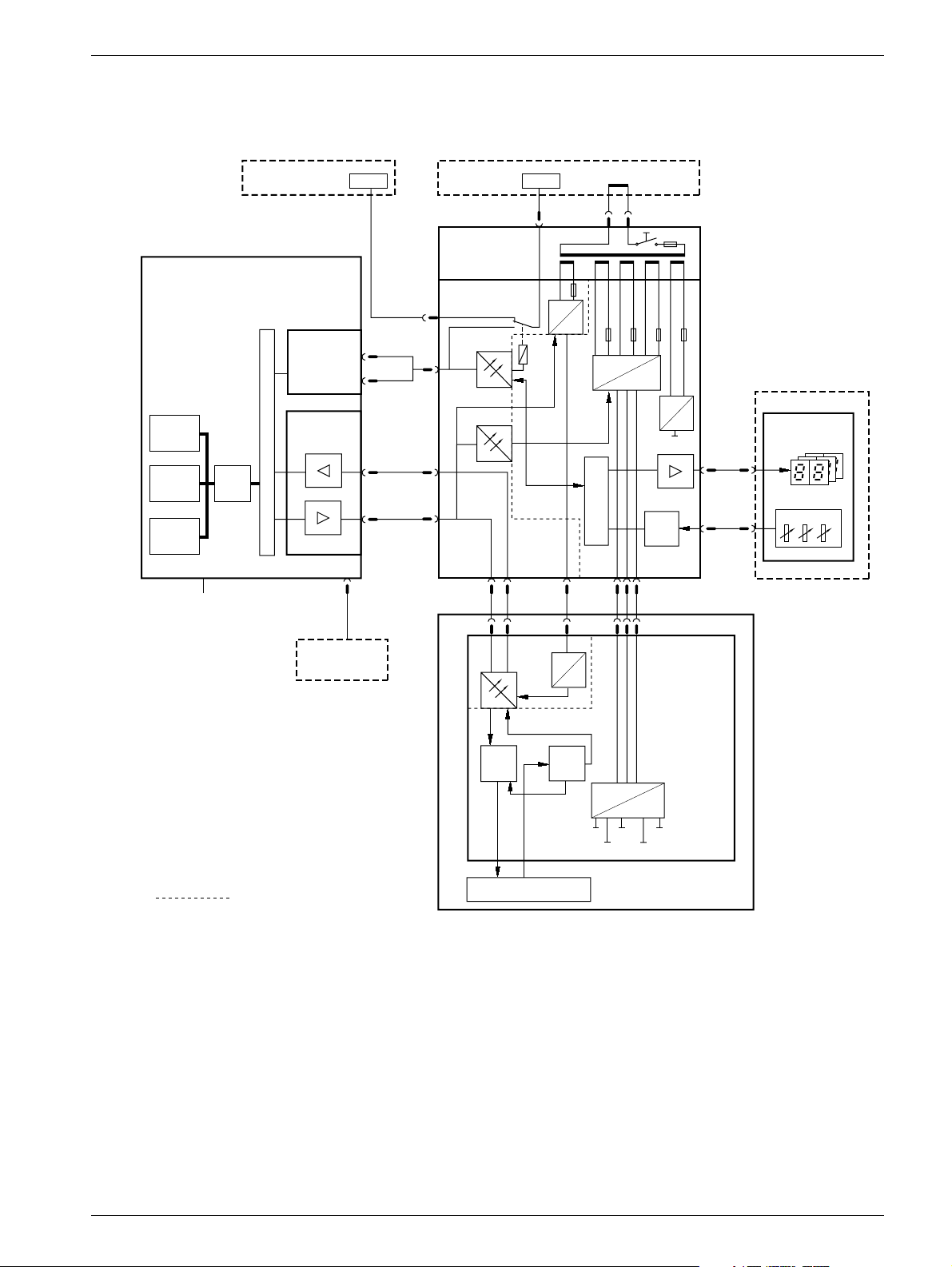
Block diagram 2
The block diagram below shows the function of the Opdimar system.
2 - 1
Workstation
System
monitor
Graphics
acc.
RAM
Incoming mains: 100, 120;
CPU
200 - 240V AC
M3000 printer /
service PC
2 x RS-232
D101 Camera
interface board
PCI BUS
PCI BUS
Printer
(option)
RS-232
A
exp. sync.
B
biopsy data
X101
12-bit image
data
RS-422
X101
control data
M3000 stand
Biopsy
controller
D200 Biopsy
control board
X205
X204
X203
X203
X206
DTR
POW_ON
X202
X111 X111 X112X110,X111
X202
RS-232
AC
DC
5V_COM
230V AC
Mains
cable
DC
AC
7V_COM
POW_ON
X202 X201
DC
CPU
DC
7V
20V
AC
30V
DC
5V
ADC
CCD camera
D110 CCD
camera board
X207
X207
X885
X885
M3000
Biopsy unit
X Y Z
Fig. 1 Block diagram
= Galvanic separation
CCD
control
logic
CCD sandwich
ADC
DC
DC
5V
C_CL
A_CL
CCD_R
SRC_CL
OPD00614
Siemens AG Register 5 SPB7-230.061.11 Page 1 of 4 Opdimar
Medical Solutions Rev. 02 07.03 CS PS 24 Service
Page 10

2 - 2 Functional description
Biopsy controller 2
The biopsy controller has three main functions:
• Biopsy unit control
• Switching of RS-232 from MAMMOMAT to either MAMMOMAT printer/service PC or
workstation
• CCD camera power supply
Biopsy unit control 2
The biopsy functions are controlled by the micro controller. In the biopsy unit there are
three potentiometers indicating the current needle position.
The values from the potentiometers are A/D converted and sent to the micro controller. To
check the converted values from the A/D converter, the potentiometer values are
converted in parallel by the micro controller.
RS-232 switching 2
To enable RS-232 communication between MAMMOMAT and either MAMMOMAT printer/
service PC or workstation, a relay is used. The relay is controlled by the workstation.
CCD camera power supply 2
The biopsy controller converts the mains AC voltage to DC voltages. The DC voltages are
used by the CCD camera.
LEDs 2
On the biopsy controller printed circuit board, D200, there are a number of LEDs with the
following meaning:
• Indication of RAM error
• Indication of PROM error
• Indication of analog/digital converter
• Indication of NVM error
• Indication of TxD error
• Selection of RS-232 communication to MAMMOMAT printer/service PC or workstation
(SELECT_WS)
• Supply voltages (e.g. 5V_COM, 30V_CC)
For more information on LEDs, see MAMMOMAT 1000/3000/3000 Nova - Opdimar
Wiring Diagram.
Opdimar Register 5 SPB7-230.061.11 Page 2 of 4 Siemens AG
Service Rev. 02 07.03 CS PS 24 Medical Solutions
Page 11
Functional description 2 - 3
Workstation 2
The workstation includes the following parts:
• Main unit, including temporary storage media i.e. hard disk
• Monitor
• Keyboard and mouse
• Internal CD drive
• External MO unit i.e. magneto-optical drive, used for the permanent storage media and
backup
The workstation is used for:
• Running application software
• Communication with the CCD camera
• Control of MAMMOMAT and biopsy unit
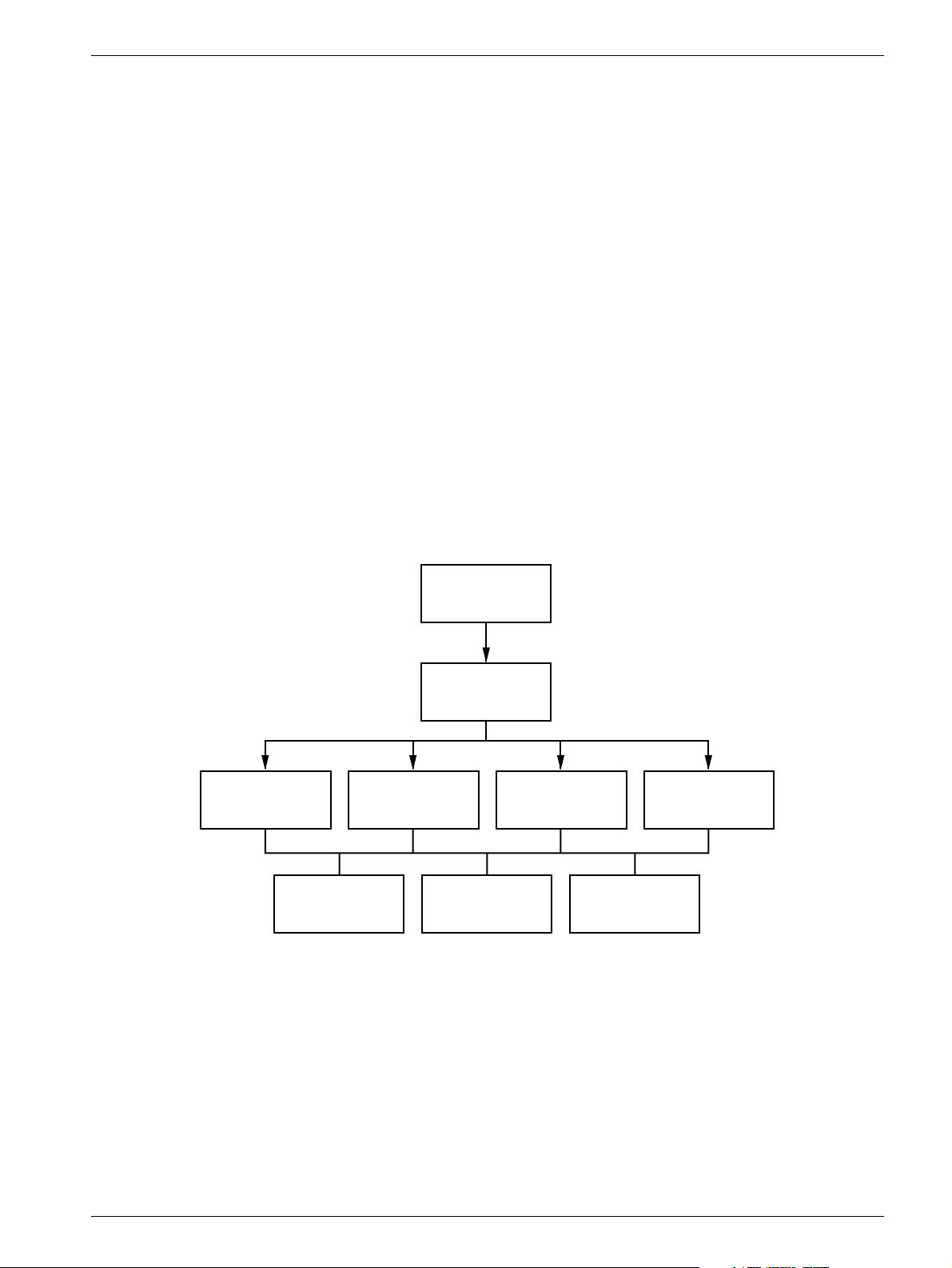
Application software 2
The application software run by the workstation is the main communication interface with
the user and units of the Opdimar system.
Stereo examination
mode
Fig. 2 Application software logic flow
Start-up and login
Mode selection
Spot examination
mode
Database
mode
Service mode
Error handlingHelp (n.a.)Data storage
OPD00595
Siemens AG Register 5 SPB7-230.061.11 Page 3 of 4 Opdimar
Medical Solutions Rev. 02 07.03 CS PS 24 Service
Page 12

2 - 4 Functional description
CCD camera communication 2
The camera interface in the workstation main unit sends commands to the CCD camera
from the workstation and receives the image from the camera. The interface adapts the
workstation data bus to RS-422.
The camera interface also supplies the CCD camera opto couplers with power.
Control of MAMMOMAT and biopsy unit 2
The workstation controls the MAMMOMAT via RS-232 communication.
Biopsy calculations are performed by the workstation and target coordinates are sent to
the biopsy unit.
Monitor 2
If the settings of the monitor has changed, set values as specified in the Monitor Installation Instruction.
CCD camera 2
The CCD camera consists of a printed circuit board, CCD sandwich and RS-422 interface.
When the x-ray beams reach the CCD sandwich, electric energy proportional to the x-ray
energy is produced. The produced electrical current is A/D converted to digital information
and sent to the workstation RAM via an RS-422 interface.
Biopsy unit 2
The biopsy unit is used for performing biopsy examinations.
The biopsy unit consists of a needle positioning device which is firmly attached to an
18 cm x 24 cm object table with a cut-out contour that is superimposed on the CCD.
External stereo diaphragm, needle support and compression plate are also included in
the biopsy unit. The biopsy unit can easily be attached to the swivel arm of the
MAMMOMAT.
There are three displays on the biopsy unit front. The displays show spatial deviation of
needle tip from the suspect point in x-, y- and z-axis calculated by the workstation.
Three potentiometers monitors the actual position of the needle tip.
Opdimar Register 5 SPB7-230.061.11 Page 4 of 4 Siemens AG
Service Rev. 02 07.03 CS PS 24 Medical Solutions
Page 13

Protective measures for CCD camera 3
3 - 1
CAUTION
CAUTION
The camera shall be used within 10230i C.
The camera shall be transported or stored within 0240i C.
The CCD camera has to be handled with extreme care, it is very
sensitive to mechanical shocks and temperature. When not connected do not touch the pins in the camera contacts. Shock and
temperature sensors are integrated in the camera.
The CCD camera is sensitive to mechanical shock and shall
always be stored in the attaché case, delivered with the system,
when disconnected from the biopsy controller.
Siemens AG Register 5 SPB7-230.061.11 Page 1 of 2 Opdimar
Medical Solutions Rev. 02 07.03 CS PS 24 Service
Page 14

3 - 2 Protective measures for CCD camera
This page intentionally left blank.
Opdimar Register 5 SPB7-230.061.11 Page 2 of 2 Siemens AG
Service Rev. 02 07.03 CS PS 24 Medical Solutions
Page 15

Protective measures 4
It is very important that any intervention in the equipment shall start with disconnecting it
from the power supply with the main circuit breaker. To prevent accidental triggering of
high voltage and radiation, set the switch S2 (SS) on board D702 to OFF (lower position,
no triggering of the SS relay).
4 - 1
CAUTION
WARNING
WARNING
When switching off the workstation use the power off procedure
described in the Supplement to the Instructions for Use MAMMOMAT 3000 - Opdimar.
Switching off the workstation before the software has been
closed down may cause damage to the files on the hard disc.
If the system is only switched off at the control panel or with S2/
D711 in the MAMMOMAT generator, line voltage will still be
present at the generator line connection, line filter Z1, Z2, transformer T1, transformer T10 and board D711 (see MAMMOMAT
1000/3000 Nova Wiring Diagram). The Opdimar is switched off
separately.
After shut-down of the system, there may still be about 380 V DC
present on the intermediate circuit of the MAMMOMAT generator.
This will be indicated by LED V24 on board D710. The voltage will
drop to less than 30 V within about 3 minutes, the LED goes out at
about 30 V.
CAUTION
Siemens AG Register 5 SPB7-230.061.11 Page 1 of 2 Opdimar
Medical Solutions Rev. 02 07.03 CS PS 24 Service
Observe the currently valid guidelines for handling electronics
endangered by electrostatic discharge.
Use ESD-equipment, ground prior to making contact and place
the components on a conductive surface.
The boards contain electrostatic highly sensitive components
requiring particular care in their handling.
Risk of damaging components.
Page 16

4 - 2 Protective measures
This page intentionally left blank.
Opdimar Register 5 SPB7-230.061.11 Page 2 of 2 Siemens AG
Service Rev. 02 07.03 CS PS 24 Medical Solutions
Page 17

Service mode 5
General 5
There are three different user levels in the Opdimar software.
• Regular user
• Administration user
• Service user
Administration users use the Service mode to perform the following tasks:
• Calibration of the biopsy unit
• Setting up needles
• User administration
• Network setup, DICOM nodes
• Backup functions
Advanced service 5
Service users can additionally access advanced service functions. To get access you
have to log in with the user name “service”. The password is obtained from Siemens Head
Quarter Support Center.
5 - 1
The following advanced service functions are included:
• Country settings
• Unit tests
• Software upgrade
• Restore disk
• Camera calibration/maintenance
• Disk cache
• Printer setup
• Log administration
• View log
NOTICE
The Opdimar external diaphragm must be used for tests and calibrations involving radiation.
Siemens AG Register 5 SPB7-230.061.11 Page 1 of 30 Opdimar
Medical Solutions Rev. 02 07.03 CS PS 24 Service
Page 18
5 - 2 Service mode
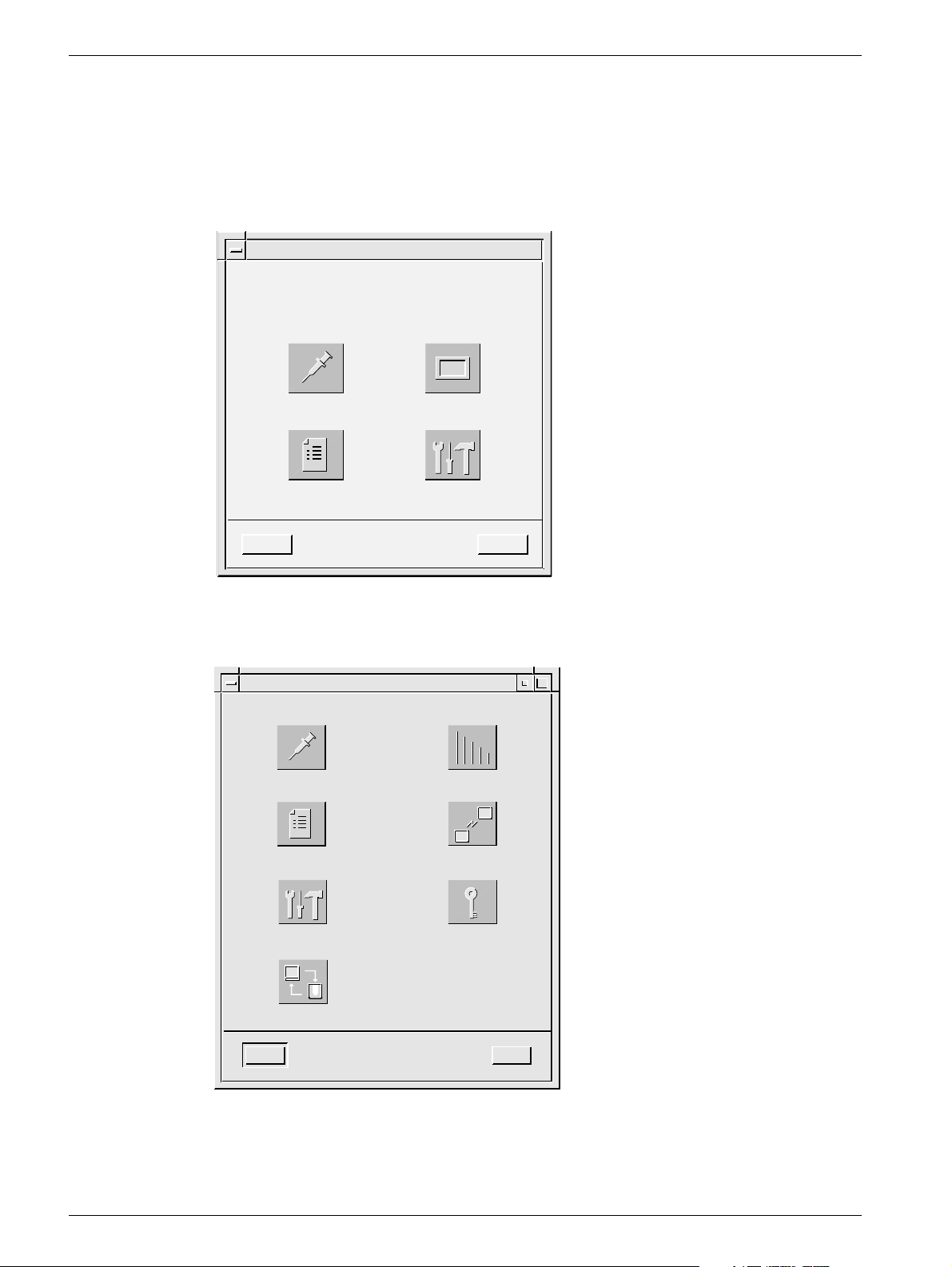
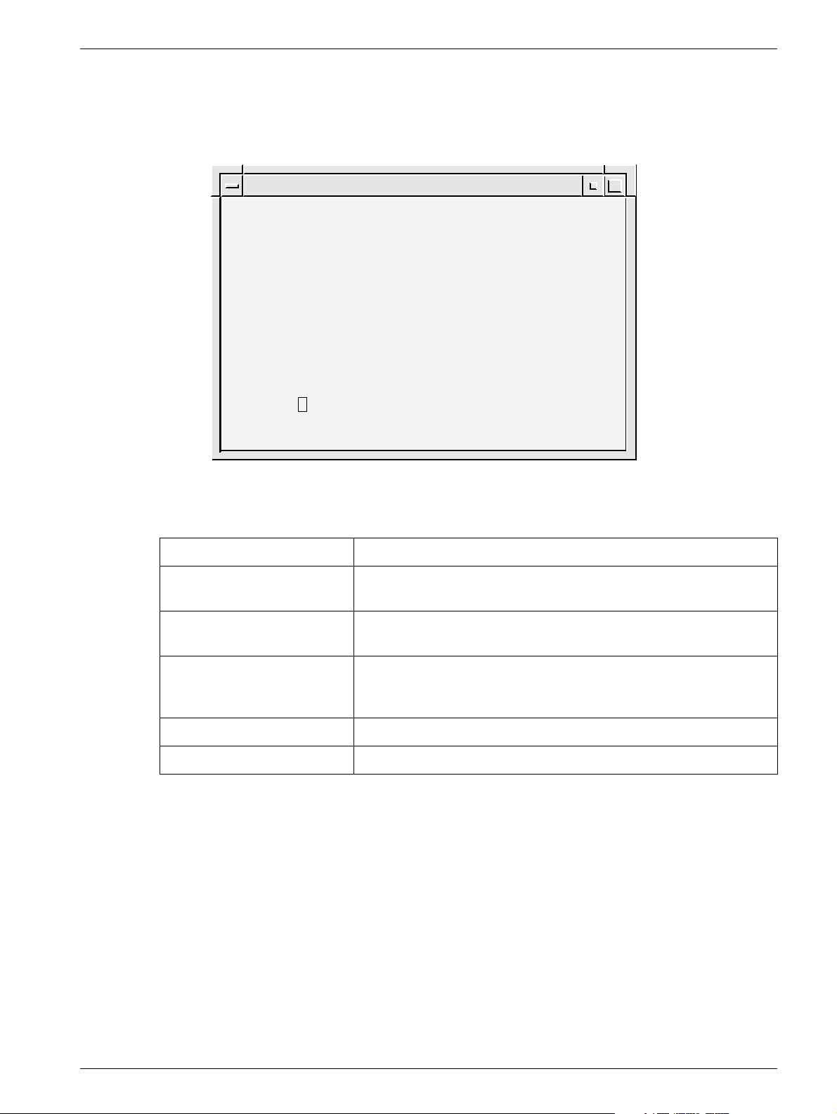
Selection of mode 5
After a successful login, the mode selection dialog is displayed.
1. Press the Service button.
Press Logout to cancel.
Mode Selection
Press a button to enter a user mode.
Stereo Spot
Database Service
Logout
Fig. 1 Mode selection dialog
Help
OPD00063
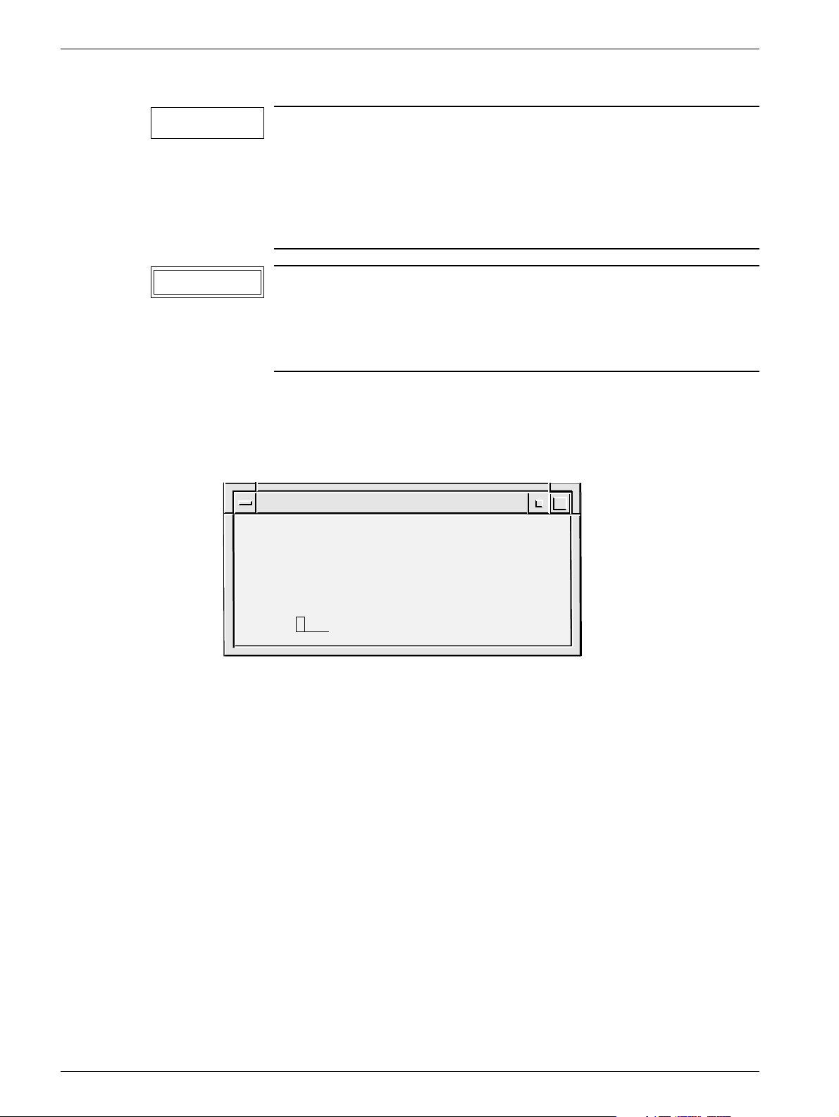
2. Select desired service function from the service dialog.
Service
Biopsy Calibration Needle Setup
User Administration
Advanced Service
Network Setup
Change Password
Backup
Close Help
OPD00433
Fig. 2 Service dialog
Opdimar Register 5 SPB7-230.061.11 Page 2 of 30 Siemens AG
Service Rev. 02 07.03 CS PS 24 Medical Solutions
Page 19
Service mode 5 - 3
Calibration of the biopsy unit 5
Calibration of the biopsy unit is carried out by using a stereo calibration phantom with
targets at fixed positions. By releasing two stereo pair exposures with a fine needle
adjusted to different targets, the system is automatically calibrated. Follow the instructions
given on the screen during the calibration procedure.
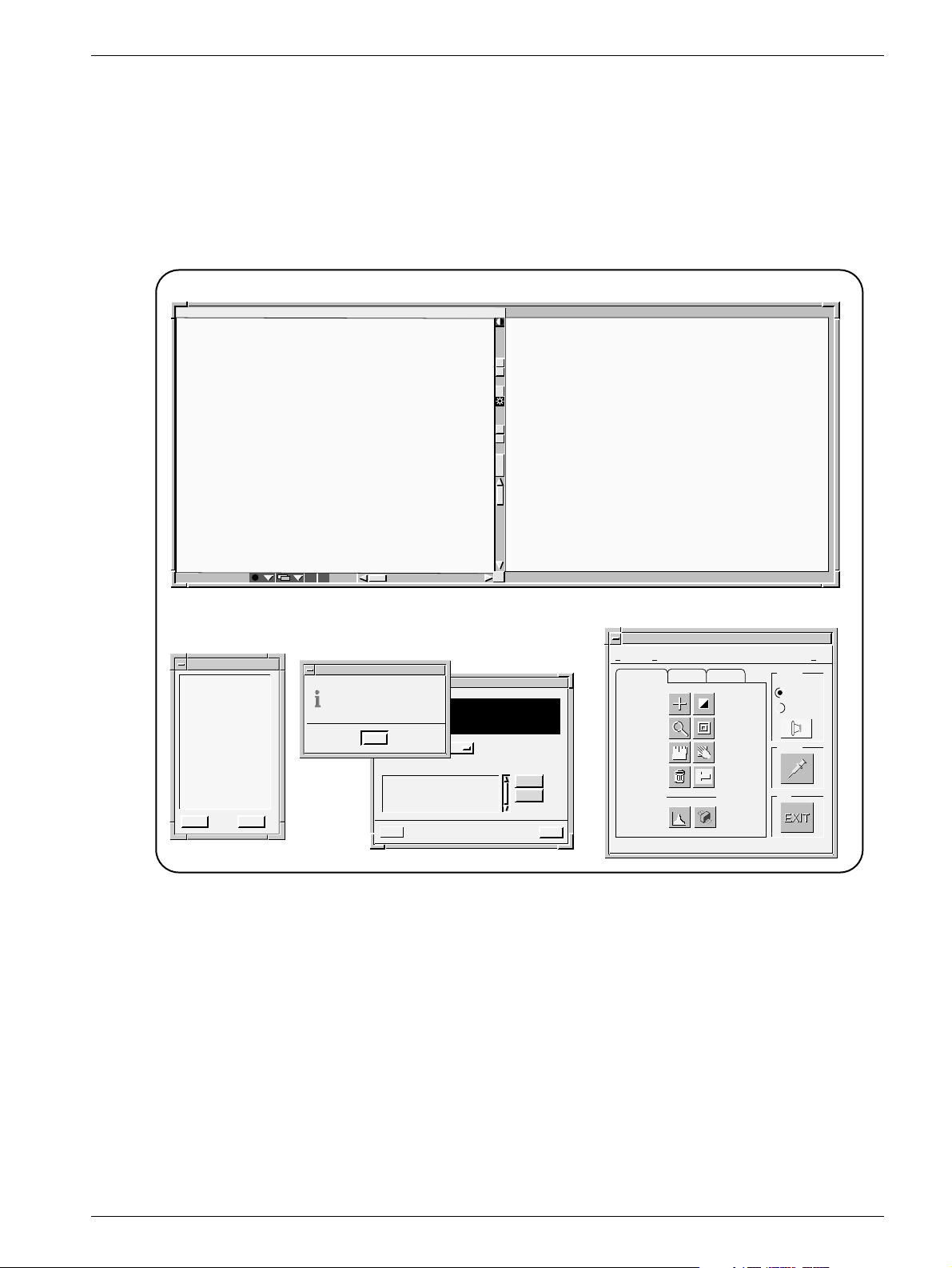
1. Press the Biopsy Calibration button in the service dialog.
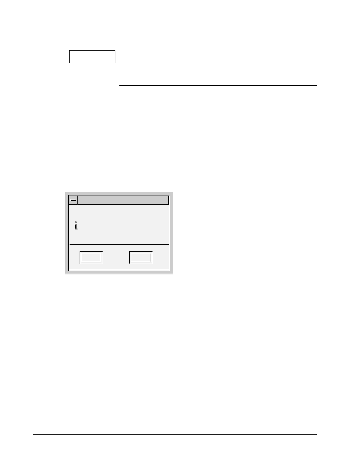
The following is shown on the screen:
Pixel x 138 value 1139 Gray scale center 1000 width 400y 152
123-45-6789
03/26/97
Help >>
i
Z
Z
1) Place and compress the stereo
calibration phantom and insert
a fine needle of suitable length.
2) Move the needle holder to the first
calibration position. 3) Remove the
needle. 4) Acquire a stereo pair of images.
Fig. 3 Dialogs during calibration
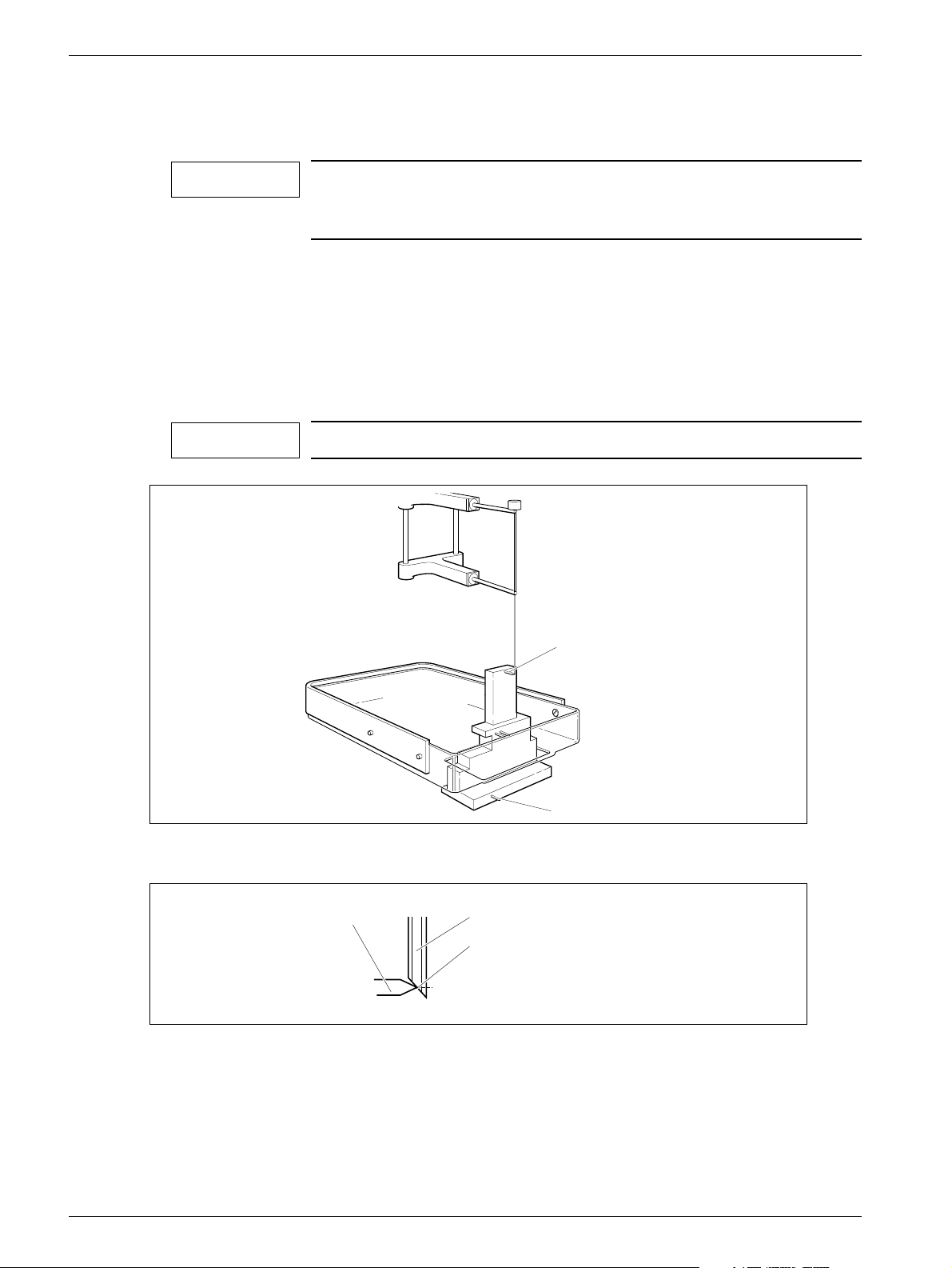
2. Place the stereo calibration phantom on the biopsy table and compress.
With the targets facing the patient side, the phantom fits in the opening of the
stereo compression plate, see Fig. 4. Target 2 shall be positioned 25228 mm in
negative x-axis direction and 12 mm from the object table side.
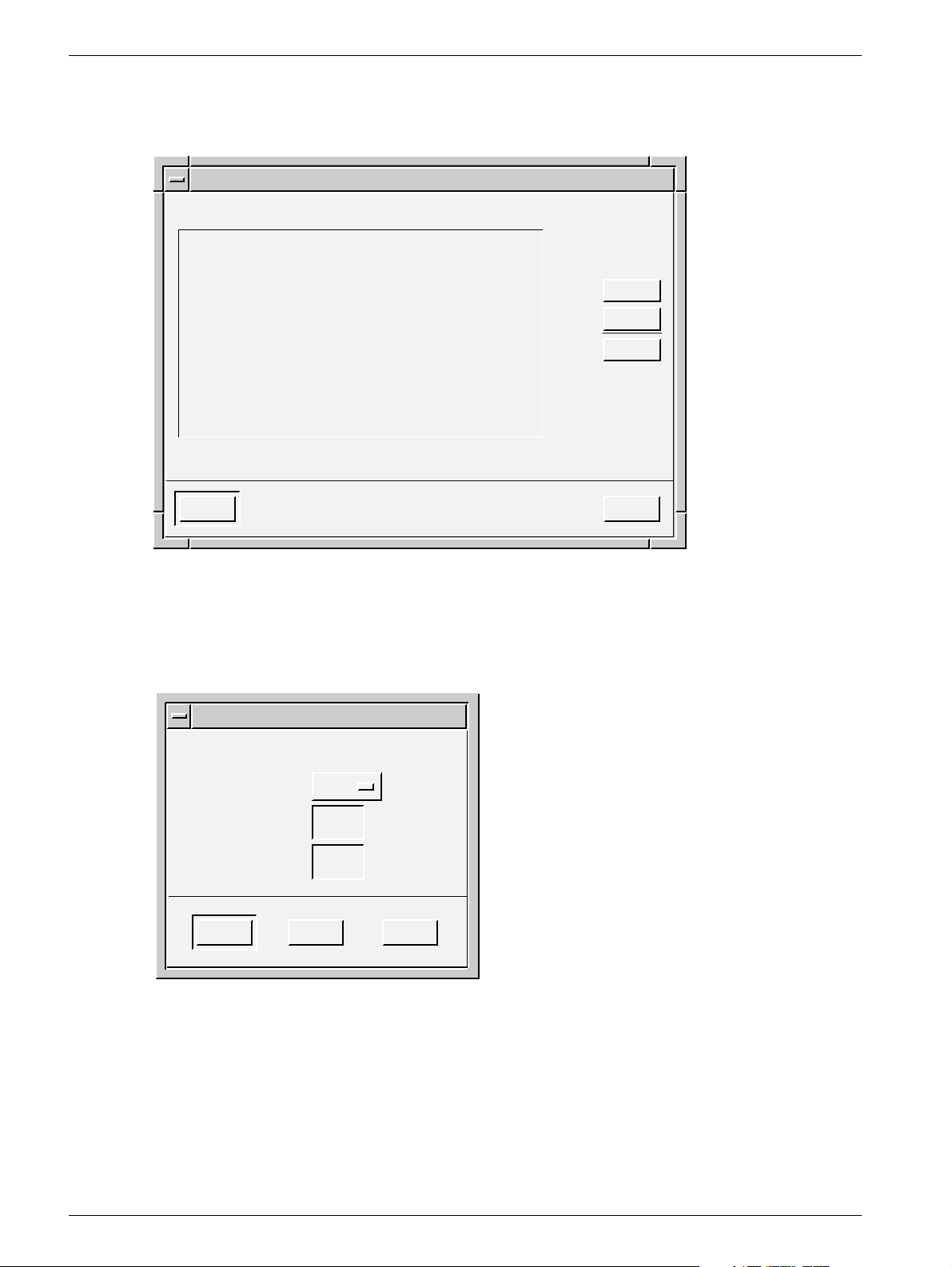
1.00x
Message
Help
Default Needle
Num. X Y Z [mm]
Close Help
Targets
Display a stereo pair!
Core 100
[mm]
Delete
Transmit
Control
Image Tools
Windows
Pointer
Magnify
Ruler
Delete
Histogram
Filters
2
Control
Layout
Invert
Zoom
Pan
Restore
Screen Dump
Help
Acquire
Single
Double
Targets
Exit
OPD00569
Siemens AG Register 5 SPB7-230.061.11 Page 3 of 30 Opdimar
Medical Solutions Rev. 02 07.03 CS PS 24 Service
Page 20
5 - 4 Service mode
3. Select a fine needle to be used and measure the length.
Measuring the needle length is described on Page 5 - 7.
NOTICE
We recommend to use a needle that measures 90 mm, this will
make it possible to avoid having to change needle while calibrating.
4. Choose Other in the Needle option menu and enter the selected needle length
(minimum 90 mm).
5. Insert needle guides corresponding with the needle diameter.
6. Insert the fine needle into the needle guides.
7. Move the needle to Target 1 of the stereo calibration phantom, see Fig. 4, by using
the adjustment knobs. Position the needle according to Fig. 5.
NOTICE
Make sure the needle is moved to Target 1.
Fig. 4 Stereo calibration phantom
Target
Fig. 5 Position of needle
8. Remove the needle.
9. Acquire and release a stereo pair of images.
Set the exposure parameters to 25 kV and 28 mAs in manual mode.
Target 1
Target 2
Fine needle
Needle channel center
OPD00512
OPD00175
Opdimar Register 5 SPB7-230.061.11 Page 4 of 30 Siemens AG
Service Rev. 02 07.03 CS PS 24 Medical Solutions
Page 21
Service mode 5 - 5
10. Check the reference marks and adjust if necessary, mark Target 1 and press
Transmit.
NOTICE
When performing the biopsy calibration set the magnification to
0.7 and change Contrast/brightness in order to find all targets in
the phantom. Be sure to mark the target at which the needle tip
was positioned.
11. Insert the fine needle into the needle support of the biopsy unit.
12. Move the needle to Target 2 of the stereo calibration phantom by using the
adjustment knobs.
13. Remove the needle.
14. Acquire and release a stereo pair of images.
Set the exposure parameters to 25 kV and 28 mAs in manual mode.
15. Check the reference marks and adjust if necessary, mark Target 2 and press
Transmit.
When the calibration is successfully calibrated, the following message is
displayed:
Message
The biopsy unit has now been
calibrated. Press EXIT!
OK
Fig. 6 Information message
Help
OPD00176
16. Perform a final check according to Verifying the calibration of the biopsy unit on
Page 10 - 1 to make sure that the biopsy unit works properly.
Siemens AG Register 5 SPB7-230.061.11 Page 5 of 30 Opdimar
Medical Solutions Rev. 02 07.03 CS PS 24 Service
Page 22
5 - 6 Service mode
Setting up needles 5
1. Press the Needle Setup button in the service dialog.
Needle Setup
Type
Fine
Core
Close Help
Fig. 7 Setting up needles dialog
L1 (mm) L2 (mm)
90.5 -
110.0 5
2. Press Add... .
You can only add needles which match the needle guides with the fixed
diameters: 0.7, 0.9, 1.2, 1.65, or 2.1 mm.
Add...
Edit...
Delete
OPD00087
Needles
Enter needle values.
L1
L2
OK Help
Fig. 8 Needle values dialog
Cancel
3. Select needle type (fine or core) from the option menu and enter needle length in
the text field.
L1 shall be 30 to 175 mm when selecting fine needle, L2 is not applicable for fine
needle. When selecting core, L1 shall be set to <170 mm.
CoreType
(mm)
(mm)
OPD00088
Opdimar Register 5 SPB7-230.061.11 Page 6 of 30 Siemens AG
Service Rev. 02 07.03 CS PS 24 Medical Solutions
Page 23
Service mode 5 - 7
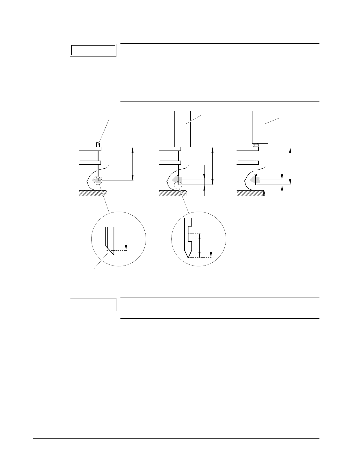
CAUTION
Fine needle
Ensure by measuring the length of the specified needle or core
gun with needle that the right values are entered.
If the stroke length of the core gun is changed, a new needle has
to be selected from the Targets dialog. The core needle length L1
shall be measured with the core needle in outer position and
mounted in the core gun.
Core gun
Core gun
with coax
L1
L2
L1
L2
L1
L1
Needle channel center
Fig. 9 Measuring of needle length
NOTICE
When using core gun, the system safety margin to avoid hitting
the biopsy table is 5 mm.
L1L2
OPD00089
Editing needle values 5
1. Select a needle from the needle setup dialog.
2. Press Edit... .
Siemens AG Register 5 SPB7-230.061.11 Page 7 of 30 Opdimar
Medical Solutions Rev. 02 07.03 CS PS 24 Service
Page 24
5 - 8 Service mode
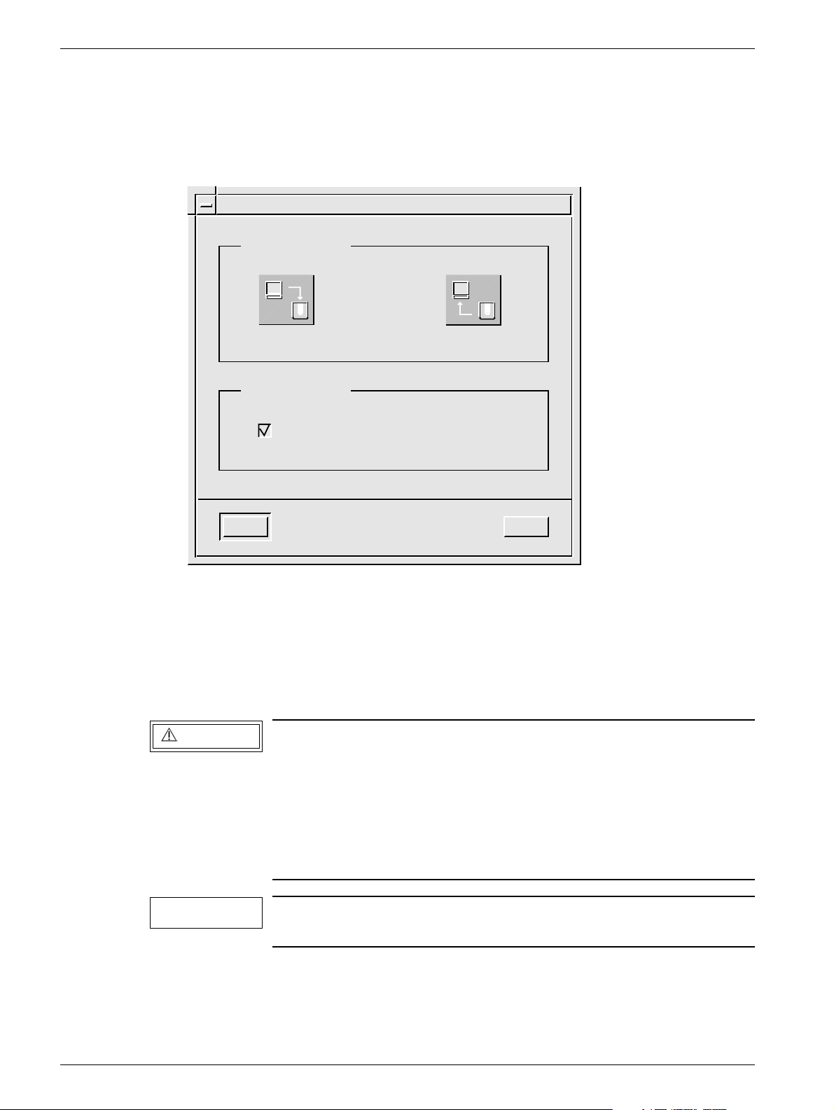
Backup of temporary storage media 5
As a service user it is possible to make a complete backup of all folders existing on the
temporary storage media (the hard disk).
1. Press the Backup button in the service dialog.
Backup
Backup / restore
Backup to MO
Setup for backup
Backup enabled
OK Help
Fig. 10 Backup dialog
Restore from MO
2. In the setup for backup section disable the backup.
3. Press the Backup to MO button.
4. Follow the instruction given in the message dialogs.
5. Enable the backup in the backup dialog.
WARNING
Backup of temporary storage media cannot replace the regular
use of backup described in Using the Backup function in Supplement to the Instructions for Use MAMMOMAT 3000 - Opdimar.
OPD00326
Backup of temporary storage media only saves the content
present on the hard disk at the actual moment. Images may have
been erased by the disk cache system (see Page 5 - 24) or software reinstallation.
NOTICE
This backup might take a long time and require several MO disks
since all folders on hard disk will be copied to backup MO.
Opdimar Register 5 SPB7-230.061.11 Page 8 of 30 Siemens AG
Service Rev. 02 07.03 CS PS 24 Medical Solutions
Page 25
Service mode 5 - 9
Use of Advanced service functions 5
General 5
To get access to the advanced service menu you have to log in with the user name
“service”. The password is obtained from Siemens Uptime Service Center (or from
Headquarter Support Center).
The advanced service is carried out by using a number of text dialogs. Selection of an
item in a dialog can be done in three different ways:
• Use the up/down arrows of the keyboard to step through the fields (underlined)
• Use the space bar to step through the fields
• Type the corresponding number or letter of the item
Press Enter to execute.
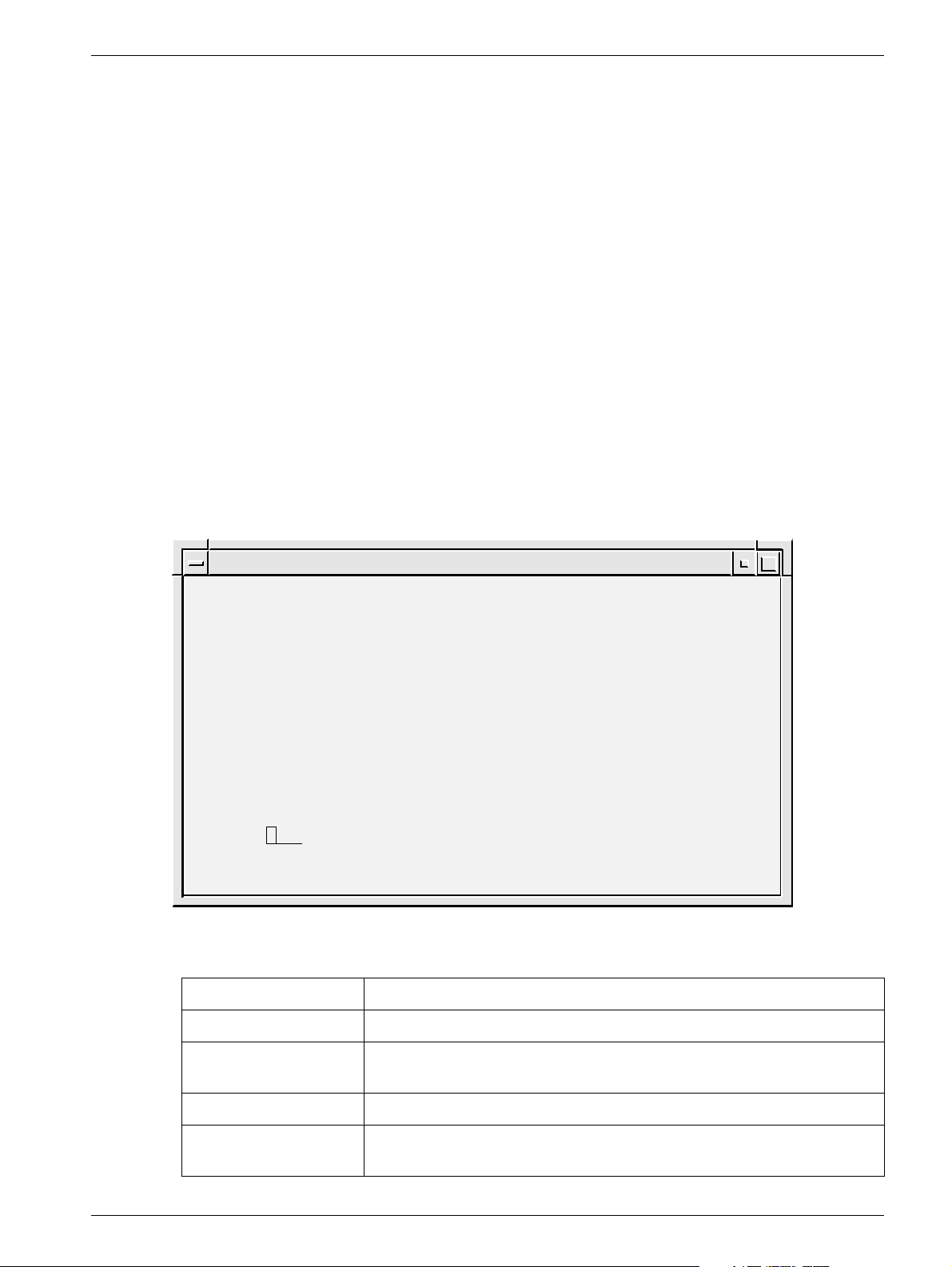
Main menu 5
The main menu is used to access all the advanced service functions.
1. Press the Advanced service button in the service dialog.
2. Select a function from the menu.
SERVICES
1.
Country Settings
2.
Unit Tests
3.
Software Upgrade
4.
Restore Disk
5.
Camera Calibration/Maintenance
6.
Disk Cache
7.
Printer Setup
8.
Log Administration
9.
View Log
Close
Help
Select: Close
Fig. 11 Advanced service dialog
Advanced Service
OPD00409
Country Settings Function for selection of country of installation (your country).
Unit Tests Function for performing tests of subassemblies.
Software Upgrade Function for performing upgrade of software and for
modifications of software.
Restore Disk Function for restoring data from MO disk.
Camera Calibration/
Maintenance
Siemens AG Register 5 SPB7-230.061.11 Page 9 of 30 Opdimar
Medical Solutions Rev. 02 07.03 CS PS 24 Service
Function for performing installation and maintenance of CCD camera.
Page 26

5 - 10 Service mode
Disk Cache Function for disk cache settings.
Printer Setup Function for setup of printer.
Log Administration Function for log settings.
View Log Function for inspection of logs.
Close Function for leaving the advanced service mode.
Opdimar Register 5 SPB7-230.061.11 Page 10 of 30 Siemens AG
Service Rev. 02 07.03 CS PS 24 Medical Solutions
Page 27
Service mode 5 - 11
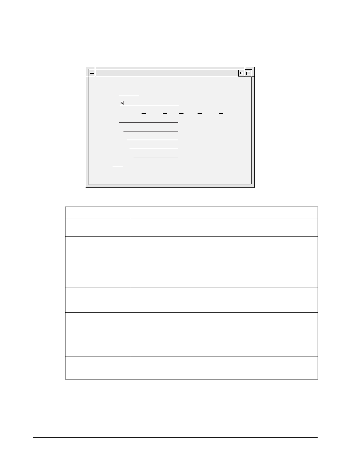
Country settings 5
National parameters are set in the country settings dialog. On delivery it contains default
settings.
Advanced Service
COUNTRY SETTINGS
Language: English
Time Zone: MET
Time Settings: Year: 2000 Month: 10 Day: 24 Hour: 09 Minute: 21
Id Pattern: 111-11-1111
Date Pattern: m/d/y
Service Center: Undefined
Institution Name: Undefined
Department Name: Undefined
Action: Close Close/Help/Apply
OPD00513
Fig. 12 Country settings dialog
Available Languages Shows the languages currently available by the system.
Language Selection of language in the dialogs. Select with space bar. If language
is changed, log out and log in to make the change take effect.
Time Zone A selection of the time zone used by the system. Select with space bar.
For faster selection, type the first letter of the desired time zone name.
Time Settings Value of system clock. If changed, Apply will reboot.
NOTICE! The database is updated every time an examination is
performed or when an image is loaded from a MO disk. The system clock cannot be set to a point earlier than the last update.
ID Pattern Selection of ID-number structure. Type pattern with the keyboard: “1”
for digit, “a” for letter, “?” for both digits and letters and an arbitrary character for punctuation mark. For example: 111-11-1111.
Date Pattern Selection of date structure. Type pattern with the keyboard: “y” for year,
“m” for month, “d” for day and an arbitrary character for punctuation
mark.
For example: m/d/y or y-m-d (do not type mm/dd/yy or yy-mm-dd).
Service Center Type the appropriate service center.
Institution Name Type the appropriate name for the institution.
Department Name Type the appropriate name for the department.
1. Select Country Settings in the advanced service dialog.
2. Set the values for Language, Time Zone, ID Pattern, Date Pattern, Service
Center, Institution Name and Department Name in each respective fields.
3. Select Apply and press Enter to execute the changes.
Siemens AG Register 5 SPB7-230.061.11 Page 11 of 30 Opdimar
Medical Solutions Rev. 02 07.03 CS PS 24 Service
Page 28
5 - 12 Service mode
Test of units 5
Advanced Service
UNIT TESTS
Unit
Test
Mammomat
Yes
Camera
Yes
Biopsy Controller
Yes
Modem
Yes
MO-Disk
Yes
Database
Yes
Action: Run Close/Help/Run
Fig. 13 Unit tests dialog
NOTICE
Status
OK
OK
OK
N/A
N/A
OK
OPD00171
Before performing unit tests, the biopsy unit needs to be
mounted to the MAMMOMAT. Otherwise the biopsy controller test
will fail.
1. Select Unit Tests in the advanced service dialog.
2. Select Yes or No to select/deselect the parts to be included in the test.
3. Select Run and press Enter.
Each unit that passes the test will be indicated with an OK message. If it does not pass, a
Failed message will appear. Units that have not been tested are indicated with an
Untested message.
The units are tested according to the following:
• MAMMOMAT - test if there is a connection and if the power is on
• CCD camera - test if there is a connection and if the power is on
• Biopsy controller - test if there is a connection and if the power is on
• Database - reading and writing in the database
Opdimar Register 5 SPB7-230.061.11 Page 12 of 30 Siemens AG
Service Rev. 02 07.03 CS PS 24 Medical Solutions
Page 29
Service mode 5 - 13
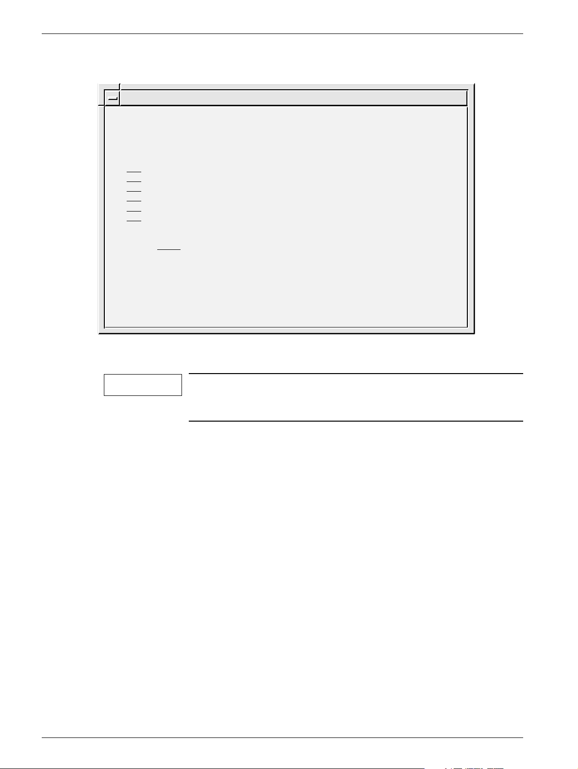
Software upgrade 5
The software upgrade dialog is used to upgrade the current software version with a new
version from CD-ROM and to do modifications of the software.
Advanced Service
SOFTWARE UPGRADE
1. New software version
2. DICOM option
3. Network settings
4. Restore hostname
5. Update eeprom
6. Miscellaneous
Close
Help
Select: Close
OPD00514
Fig. 14 Software upgrade dialog
New software version Upgrade with new version from CD-ROM.
DICOM option Enabling the DICOM option.
NOTICE! A license key is necessary to install DICOM.
Network settings Function for defining the network settings for the Opdimar sys-
tem.
Restore hostname The hostname of the original workstation can be restored to a
new workstation.
Restore hostname from most recently used local/backup MO disk.
Update eeprom Not applicable.
Miscellaneous Database and MO disk utilities.
Siemens AG Register 5 SPB7-230.061.11 Page 13 of 30 Opdimar
Medical Solutions Rev. 02 07.03 CS PS 24 Service
Page 30
5 - 14 Service mode
New software version 5
NOTICE
This menu will be used when installing the next version of
software.
However it is not applicable when changing from ASW 2.1 to 3.1
because of the change of the Solaris version. If the change from
ASW 2.1 to 3.1 shall be done use the present instrucions in the
modification instructions when installing the new software.
CAUTION
Make sure that all examinations are stored on the
MO disk before upgrading. The examinations are stored when
exiting an examination or database session, see Storing data on
MO disk in Supplement to the Instructions for Use MAMMOMAT
3000 - Opdimar.
1. Select Advanced service in the Service mode.
2. Insert the CD-ROM for the new ASW software version.
3. Select Software upgrade and New software version.
Advanced Service
NEW SOFTWARE VERSION
Current Release: opdima.3.0_6633064
CD-ROM Release: opdima.3.1_6633700
Action: Close Close/Help/Install
Fig. 15 New software version, advanced service dialog
4. Select Install.
OPD00614
Opdimar Register 5 SPB7-230.061.11 Page 14 of 30 Siemens AG
Service Rev. 02 07.03 CS PS 24 Medical Solutions
Page 31

Service mode 5 - 15
Enabling the DICOM option 5
To enable the DICOM option you need the DICOM license key that is received when
purchasing the DICOM option.
The DICOM licence is written on the invoice and the dispatch note. If not, please contact
Siemens AG Medical Solutions in Erlangen, Headquarter Support Center of Special Products Division (Dept. CS HSC 24) via phone (+49/ (0) 9191 18 8080.1.6.3) for further information. This department will ask for serial No. and host ID of the workstation in question.
Instruction for obtaining the systems host ID and hostname 5
1. Switch on the workstation.
2. Log in as service user.
3. Press the Control, Alt, Shift and ! keys at the keyboard simultaneously.
4. Switch to default behavior?
Press OK. The screen will flash for a second.
5. Place the mouse pointer on the screen background and press the rightmost
mouse button.
6. Select New window.
7. Type “hostname” and press Enter.
NOTICE
8. Type “hostid” and press Enter.
NOTICE
9. Type “exit” and press Enter.
10. Press the Control, Alt, Shift and ! keys at the keyboard simultaneously.
11. Switch to custom behavior?
Press OK. The screen will flash for a second.
12. Done!
Note the hostname (opdxxxx) shown on the screen.
Note the host id (xxxxxxxx) shown on the screen.
Siemens AG Register 5 SPB7-230.061.11 Page 15 of 30 Opdimar
Medical Solutions Rev. 02 07.03 CS PS 24 Service
Page 32

5 - 16 Service mode
DICOM option
1. Select Advanced service in the Service mode.
2. Select Software Upgrade.
3. Select DICOM option.
Advanced Service
DICOM OPTION
Enabled License key
No Undefined
Action: Close Close/Help/Apply
OPD00437
Fig. 16 DICOM option, advanced service dialog
4. Select Yes.
5. Enter License key and Apply.
6. Select y to reboot.
7. Configure DICOM nodes according to Network Setup in Supplement to the
Instructions for Use MAMMOMAT 3000 - Opdimar.
Opdimar Register 5 SPB7-230.061.11 Page 16 of 30 Siemens AG
Service Rev. 02 07.03 CS PS 24 Medical Solutions
Page 33

Service mode 5 - 17
Network settings 5
Enable network
1. Select Advanced service in the Service mode.
2. Select Software upgrade and Network settings.
3. Supply appropriate values for the network settings into the fields and apply.
(The values shall be supplied by the network administrator at the hospital.)
Advanced Service
NETWORK SETTINGS
Network enabled for this host, opd1190: Yes
IP address: 123.123.123.11
Netmask: 255.255.255.0
Default router: 123.123.123.22
Action: Close Close/Help/Apply/Pingtest
OPD00518
Fig. 17 Network settings
IP address Address for the system in the network, written as four decimal
numbers separated by periods, e.g. 123.123.123.11.
No initial 0, e.g. 10.10.10.10 is OK but 010.010.010.01 is
not OK.
Netmask Netmask used in the network if IP standard subnetting is used.
Default router The IP address of the default router, if this is used in the network.
No initial 0, e.g. 10.10.10.10 is OK but 010.010.010.01 is
not OK.
4. Select y to enable the network. The workstation will be turned off.
5. Connect the network cable.
6. Switch on the workstation.
Pingtest
A pingtest checks that the default router is alive, it can be performed when the network is
enabled.
1. Select Pingtest in the Network settings dialog.
NOTICE
Some alive routers do not reply to pingtest, check with network
administrator.
To test if a host is alive or not, write the IP address temporarily in the field for Default
router and perform a pingtest.
Siemens AG Register 5 SPB7-230.061.11 Page 17 of 30 Opdimar
Medical Solutions Rev. 02 07.03 CS PS 24 Service
Page 34

5 - 18 Service mode
Miscellaneous 5
1. Select Advanced service in the Service mode.
2. Select Miscellaneous.
Advanced Service
MISCELLANEOUS
Options
1. Check database
2. Inspect database contents
3. MO disk utilities
4. Turn screen lock on/off
5. Select monitor type
Close
Help
Select: Close
OPD00616
Fig. 18 Miscellaneous, advanced service dialog
Check database
This will check and adjust invalid folder names that may have been introduced in earlier
software versions.
1. Select “Check database” in the miscellaneous dialog.
Advanced Service
CHECK DATABASE
Check:
Yes MO Disk
Yes Local Database
Action: Close Close/Help/Run
OPD00441
Fig. 19 Check database, advanced service dialog
2. Select the database to check, MO Disk and/or Local Database.
3. Select Run.
Opdimar Register 5 SPB7-230.061.11 Page 18 of 30 Siemens AG
Service Rev. 02 07.03 CS PS 24 Medical Solutions
Page 35

Service mode 5 - 19
Inspect database contents
1. Select “Inspect database contents” in the miscellaneous dialog.
A Text Editor window with a log file will appear on the screen, see example in
Appendix 1.
NOTICE
The log file is only a print-out of the data in the database.
Changes in the log file will NOT affect the database.
2. When done, close the Text Editor window.
MO disk utilities
Advanced Service
MO DISK UTILITIES
Options:
1. Check MO disk
2. Repair MO disk
3. View output from latest "Repair MO disk" execution
4. Identify MO disk
5. List MO directories and files
6. Create clean MO disk
Close
Help
Select: Close
Fig. 20 MO disk utilities, advanced service dialog
OPD00517
Check MO disk Check MO disk file system integrity.
Repair MO disk Repair MO disk file system.
NOTICE! Run only if Check MO disk shows that something
has to be done.
View output Lists output from latest “Repair MO disk” execution.
Identify MO disk Shows the kind of disk (local storage/backup/transfer...).
List MO directories and files View contents of MO disk.
Create a clean MO disk Format a new disk or erase contents of a formerly used disk.
WARNING! Use with extreme caution. Erases all content on
MO disk.
WARNING! When using this function, It is only possible to
use a 9.1 GB MO disk.
Siemens AG Register 5 SPB7-230.061.11 Page 19 of 30 Opdimar
Medical Solutions Rev. 02 07.03 CS PS 24 Service
Page 36

5 - 20 Service mode
Turn screen lock on/off
In this dialog it is possible to enable or disable the screen lock function.
1. Select “turn screen lock on/off” in the miscellaneous dialog.
Advanced Service
SCREEN LOCK
Enabled
No
Action: Close Close/Help/Apply
OPD00623
Fig. 21 Turn screen lock on/off, advanced service dialog
2. Select Yes to turn the screen lock on or No to turn it off.
3. Select Apply.
NOTICE
To enable the new settings log out and log in again.
Select monitor type
In this dialog it is possible to select monitor type.
WARNING
Changing the refresh rate shall be used with extreme caution and
only if instructed to do so.
1. Choose “select monitor type” in the miscellaneous dialog.
Advanced Service
MONITOR TYPE
Refresh rate: 67 Hz
Action: Close Close/Help/Apply
OPD00624
Fig. 22 Turn screen lock on/off, advanced service dialog
2. Select refresh rate according to the chapter Installation of monitor in the
Installation and Start-Up Instructions.
3. Select Apply.
NOTICE
Opdimar Register 5 SPB7-230.061.11 Page 20 of 30 Siemens AG
Service Rev. 02 07.03 CS PS 24 Medical Solutions
To enable the new settings reboot the system.
Page 37

Service mode 5 - 21
Restoring data from MO disk 5
Copies the database from the MO disk to the hard disk. It is possible to use a local
storage MO disk or a backup MO disk.
Advanced Service
RESTORE DISK
MO-Disk: /opdxxxx/3
Last Backup: 990908
Action: Restore Close/Help/Restore
OPD00460
Fig. 23 Restore disk dialog
MO disk Name of the inserted MO disk.
Last backup Last date for storing on the MO disk.
1. Insert the most recently used MO disk in the MO unit.
2. Select Restore Disk in the advanced service dialog.
3. Select Restore and press Enter to copy the data to the hard disk.
WARNING
When restoring data, be sure to insert the MO disk that was used
most recently before the reinstallation of software.
Date for last update of MO disk is displayed on the monitor before
confirmation of restore.
If the system is restored from an older MO disk, the most recent
folders will be lost from the database and the new MO disk numbering can be incorrect. Please contact HSC for more information.
NOTICE
Set up the printer once again after software reinstallation.
Printer info can not be restored.
Siemens AG Register 5 SPB7-230.061.11 Page 21 of 30 Opdimar
Medical Solutions Rev. 02 07.03 CS PS 24 Service
Page 38

5 - 22 Service mode
CCD camera calibration and maintenance 5
Advanced Service
CAMERA CALIBRATION/MAINTENANCE
Action: Run Close/Help/Run
OPD00411
Fig. 24 Camera calibration/maintenance
NOTICE
This calibration shall be performed with the object table (grid or
non grid) that the customer is going to use in most cases.
NOTICE
Do not use the stereo table when calibrating.
Fill in your values in the test protocol for CCD camera calibration (see Appendix 2).
Grid table 5
1. To avoid grid lines in the calibration images, temporary increase the grid speed
during calibration as follows:
Change the grid fast speed time to 1500 ms, the grid fast speed to 99% of max
and the grid slow speed to 40% of max (Fig. 25) using the service PC.
Main menu
Configuration
Service
Normal mode
Test DUEP Communic.
Backup
Quit
Configuration
System type
Anode
Show configuration file
Save configuration file
AEC
Miscellaneous
Filament
Power
Clock
Compression
Lift
Rotation
Grid speed
Beam limiting device
Grid
Grid fast speed time 1500
Grid fast speed 99
Grid slow speed 40
<ESC> to exit, <TAB> move to next entry field
1 Help 2 Save 3 45678910Quit
ms (2.5 s max)
% of max
% of max
OPD00491
Fig. 25
Opdimar Register 5 SPB7-230.061.11 Page 22 of 30 Siemens AG
Service Rev. 02 07.03 CS PS 24 Medical Solutions
Page 39

Service mode 5 - 23
2. Place 2 plates calibration plexiglas 19 mm on the table, covering the CCD.
3. Select Camera Calibration/Maintenance in the advanced service dialog.
4. Select Run and set 27 kV, Mo/Mo and AEC mode, on the generator.
Follow the instructions displayed on the screen.
Between each exposure the acrylic plastic shall be moved slightly (the reason
being that impurities in the plastic shall not influence the calibration).
After the exposure series, correction tables will be calculated. This will take 10
minutes at most.
After a successful calibration (10 exposures in each mode - normal resolution and
high) the message “Camera successfully calibrated” will appear on the screen.
5. Change the grid speed back to original values.
6. Perform check of Opdimar AEC and check of resolution. See Check of Opdima
AEC on Page 10 - 2
Non grid table 5
1. Place 1 plate calibration plexiglas 19 mm and one plate calibration plexiglas
9.7 mm on the table, covering the CCD.
and Check of resolution on Page 10 - 4.
2. Select Camera Calibration/Maintenance in the advanced service dialog.
3. Select Run and set 26 kV, Mo/Mo and AEC mode, on the generator.
Follow the instructions displayed on the screen.
Between each exposure the acrylic plastic shall be moved slightly (the reason
being that impurities in the plastic shall not influence the calibration).
After the exposure series, correction tables will be calculated. This will take 10
minutes at most.
After a successful calibration (10 exposures in each mode - normal resolution and
high) the message “Camera successfully calibrated” will appear on the screen.
4. Perform check of Opdimar AEC and check of resolution. See Check of Opdima
AEC on Page 10 - 2
and Check of resolution on Page 10 - 4.
Siemens AG Register 5 SPB7-230.061.11 Page 23 of 30 Opdimar
Medical Solutions Rev. 02 07.03 CS PS 24 Service
Page 40

5 - 24 Service mode
Disk cache settings 5
Storage parameters can be set in the disk cache dialog:
Advanced Service
DISK CACHE
Clean cache trigger: 75 %
Number of images to clean: 50
Action: Apply Close/Help/Apply
OPD00461
Fig. 26 Disk cache dialog
Clean cache trigger Cleans a number of images from the cache memory (the temporary
storage media i.e. hard disk) when it has been filled up to a percentage
of the capacity. Normally set to 75%.
Number of images to
clean
The number of images to erase once the trigger level has been
reached. Normally set to 50.
1. Select Disk Cache in the advanced service dialog.
2. Set the values.
3. Select Apply and press Enter.
Every time an examination is performed a folder containing the image file, the image icons
and the image header file is created. When an examination is finished the complete folder
is copied to the MO disk. If a folder has been copied to a MO disk, its images will be
erased from the hard disk if the cache limit is reached.
Opdimar Register 5 SPB7-230.061.11 Page 24 of 30 Siemens AG
Service Rev. 02 07.03 CS PS 24 Medical Solutions
Page 41

Service mode 5 - 25
Use of printer setup 5
Stand alone Opdima system 5
NOTICE
PRINTER SETUP
Printer Alternatives:
none
ps_net PostScript network printer
ps_par PostScript parallel printer
scaled Codonics NP-1600 scaled
Selection: none
Action: Apply Close/Help/Apply
Fig. 27 Printer setup dialog
Connection of stand alone printer used for screen dump.
1. Select printer by pressing the Space button.
Advanced Service
OPD00412
1.1 ps_net: PostScript network printer, for postscript printer connected to the
network connector of the workstation see 7/Fig. 9 on Page 6 - 9. The
printer IP address has to be set to 10.10.10.2.
1.2 ps_par: PostScript parallel printer, for postscript printer connected to the
parallel port of the workstation see 8/Fig. 9. on Page 6 - 9.
1.3 scaled: Codonics NP-1660 or NP-1600 scaled, for a Codonics printer
connected to the network connector of the workstation see 7/Fig. 9 on
Page 6 - 9. The printer IP address has to be set to 10.10.10.2.
2. Select Apply and press Enter.
3. Connect your selected printer after turning off the system.
NOTICE
If no printer is connected select none, apply and restart the system.
Siemens AG Register 5 SPB7-230.061.11 Page 25 of 30 Opdimar
Medical Solutions Rev. 02 07.03 CS PS 24 Service
Page 42

5 - 26 Service mode
Networked Opdima system 5
NOTICE
Fig. 28 Printer setup dialog when connected to a network
Connection of networked printer used for screen dump.
Advanced Service
PRINTER SETUP
1. Add access to network printer
2. Remove access to network printer
3. Select printer
Close
Help
Select: Close
OPD00428
When the Opdimar system is connected to a network (see Page 5 - 17) it can be
configured to print on a printer connected to the network. Supported printer types are
postscript printers and printers that can handle XWD files (X Window Dump).
Add access to network printer
Advanced Service
ADD NETWORK PRINTER
Printer name: mammo_printer
Description: Codonics_mammo_dept
Address: 123.123.123.33
(Remote name: scaled )
Printer type: XWD
Action: Close Close/Help/Apply
OPD00527
Fig. 29 Add network printer dialog
Printer name: Logical name presented when selecting printer in Advanced
service. No space characters are allowed. E.g. mammo_printer.
Description: Textual description, for example the location of the printer. E.g.
Codonics_mammo_dept.
Address: IP address for printer, e.g. 123.123.123.33.
No initial 0, e.g. 10.10.10.10 is OK but 010.010.010.01 is not OK.
Opdimar Register 5 SPB7-230.061.11 Page 26 of 30 Siemens AG
Service Rev. 02 07.03 CS PS 24 Medical Solutions
Page 43

Service mode 5 - 27
Remote name: Name of printer at remote system. No space characters are
allowed.
NOTICE! The remote name “scaled” must be used when
using a Codonics printer.
Printer type: PS or XWD. Use PS for all postscript printers.
NOTICE! XWD shall be used with Codonics printers.
Select printer
Advanced Service
SELECT PRINTER
Printer Alternatives:
none
ps_par PostScript parallel printer
mammo_printer Codonics_mammo_dept
Selection: mammo_printer
Action: Close Close/Help/Apply
OPD00528
Fig. 30 Select printer dialog, example
Note that only ps-par and network printers that have been added can be selected when
the network has been enabled for the system.
Remove access to network printer
Advanced Service
REMOVE NETWORK PRINTER
Printers:
mammo_printer XWD 123.123.123.33 Codonics_mammo_dept
Selection: mammo_printer
Action: Close Close/Help/Apply
OPD00529
Fig. 31 Remove network printer dialog, example
Previously defined printers can be removed from the list of printers. Note that the printer
that is currently selected cannot be removed.
Siemens AG Register 5 SPB7-230.061.11 Page 27 of 30 Opdimar
Medical Solutions Rev. 02 07.03 CS PS 24 Service
Page 44

5 - 28 Service mode
Log administration 5
Log files are stored on the temporary storage media and on the MO disks. In the log
administration dialog, the logging can be turned on/off.
WARNING
LOG ADMINISTRATION
Log
System Log
Error Log
Activity Log
Maintenance Log
Action: Apply Close/Help/Apply
Fig. 32 Log administration dialog
Do not disable loggings unless especially specified to do so.
1. Select Log Administration in the advanced service dialog.
Enabled
Yes
Yes
Yes
Yes
Advanced Service
Size
N/A
N/A
N/A
N/A
OPD00184
2. Select Yes/No to turn on/off each respective log.
3. Select Apply and press Enter.
Opdimar Register 5 SPB7-230.061.11 Page 28 of 30 Siemens AG
Service Rev. 02 07.03 CS PS 24 Medical Solutions
Page 45

Service mode 5 - 29
Log inspection 5
Through the view log dialog, the log files can be inspected.
Advanced Service
VIEW LOG
1. Message Log
2. Error Log
3. Activity Log
4. Service Log
5. Backup Log
C. Close
H. Help
Select: Close
OPD00414
Fig. 33 View log dialog
Message Log Log for messages presented to the user.
Error Log Log for Opdimar related errors.
Activity Log Log for all user activities.
Service Log Log for activities in service mode.
Backup Log Log for activities made in backup mode.
Close Function for leaving the view log dialog.
1. Select View Log in the advanced service dialog.
2. Select a log from the menu in the view log dialog.
Siemens AG Register 5 SPB7-230.061.11 Page 29 of 30 Opdimar
Medical Solutions Rev. 02 07.03 CS PS 24 Service
Page 46

5 - 30 Service mode
This page intentionally left blank.
Opdimar Register 5 SPB7-230.061.11 Page 30 of 30 Siemens AG
Service Rev. 02 07.03 CS PS 24 Medical Solutions
Page 47

Removal and replacement of sub-assemblies 6
General 6
After performing hardware service, protective earth measurement has to be performed,
see Protective earth measurement on Page 10 - 5.
6 - 1
WARNING
CAUTION
Switch off the power to the system at the main circuit breaker
after power off.
If the workstation shall be powered off, use the “poweroff” command and make sure that the system has completed the process
before switching off any main power. If power to the workstation
is disabled during the power off sequence or without using the
“poweroff” command, data could be lost.
MO unit 6
OPD00601
Fig. 1 The MO unit, front view
Removing the MO unit 6
NOTICE
1. Disconnect the power supply cable (AC in) and SCSI cable from the back of the
unit (Fig. 2).
2. Unplug the SCSI terminator from the back of the unit (Fig. 2).
3. Remove the unit.
If MO unit is defective, the complete unit must be replaced.
Siemens AG Register 5 SPB7-230.061.11 Page 1 of 14 Opdimar
Medical Solutions Rev. 02 07.03 CS PS 24 Service
Page 48

6 - 2 Removal and replacement of sub-assemblies
Installing the MO unit 6
BUSY
POWER
NOTICE
Make sure that the SCSI cables are properly connected and fixed
to the units and that the cable behind the MO unit is not bent to
much. Also, check that the MO unit is terminated correctly. If not,
this might generate a lot of problems e.g. failure to write images
to MO disk, corrupted MO disk or corrupted hard disk.
SCSI ID Disk drive type Disk drive function
1 Magneto-optical drive Permanent storage and backup media
(MO disk)
Front Panel
A1BCDEFGH
0
EJECT
2
1
3
4
5
6
SCSI CONNECTOR
7
Rear Panel
SCSI ID
9
8
10
AC IN
F.GND
11
12
POWER switch
1
2
POWER indicator
3
BUSY indicator
4
Disk insertion slot
5
Emergency eject hole
6
EJECT button
Fig. 2 MO unit, front and rear panel
7
Function switches
8
SCSI ID switch
9
SCSI connectors
10
Air duct
11
F.GND (frame ground) terminal
12
AC IN (AC power) connector
OPD00625
Opdimar Register 5 SPB7-230.061.11 Page 2 of 14 Siemens AG
Service Rev. 02 07.03 CS PS 24 Medical Solutions
Page 49

Removal and replacement of sub-assemblies 6 - 3
1. Set SCSI ID switch to 1 (SCSI address).
2. Set the function switches (see pos 7 / Fig. 2) according to Fig. 3.
A1BCDEFGH
0
Fig. 3 Function switches setting
3. Connect the power supply cable, the SCSI terminator and the SCSI cable to the
unit.
OPD00633
Tests and Adjustments 6
1. Switch on the system.
2. Ensure that the system is operating properly.
Siemens AG Register 5 SPB7-230.061.11 Page 3 of 14 Opdimar
Medical Solutions Rev. 02 07.03 CS PS 24 Service
Page 50

6 - 4 Removal and replacement of sub-assemblies
Biopsy controller 6
Removal of biopsy controller 6
The biopsy controller is attached to the stand rear side. To remove the unit proceed as
follows:
1. Remove the CCD camera and store it in its attaché case.
CAUTION
Do not touch the pins in the contacts of the camera.
The CCD camera is sensitive to mechanical shock and shall
always be stored in the attaché case when disconnected from the
biopsy controller.
2. Remove the biopsy controller cable duct.
3. Disconnect all cables.
4. Lift off the biopsy controller (1/Fig. 4) from the holders of the stand (2/Fig. 4).
WARNING
If the MAMMOMAT power is switched on, there is mains voltage
present at the biopsy controller mains cord connector.
2
1
OPD00152
Fig. 4 Biopsy controller
Opdimar Register 5 SPB7-230.061.11 Page 4 of 14 Siemens AG
Service Rev. 02 07.03 CS PS 24 Medical Solutions
Page 51

Removal and replacement of sub-assemblies 6 - 5
Removal of biopsy controller cover 6
To remove the cover of the biopsy controller, proceed as follows:
1. Remove the 13 screws (4/Fig. 5) on the back side of the biopsy controller.
2. Remove the seven countersunk screws (2/Fig. 5) on the sides of the biopsy
controller.
3. Lift off the cover, starting at the top.
1243 5
7
Fig. 5 Removal of cover
6
OPD00186
Replacement of components in the biopsy controller 6
Replacement of board D200
To replace the board D200 in the biopsy controller, proceed as follows:
1. Remove the screws (3/Fig. 5) holding the connectors X201, X202, X206, X207,
X208.
2. Loosen the four screws (1/Fig. 5) on the back side of the biopsy controller.
3. Loosen the four screws (7/Fig. 5) on the side of the biopsy controller.
4. Remove the screws (6/Fig. 5) holding the board.
5. Remove the board and install the new board. If necessary, loosen the transformer.
Make sure to replace the isolation film at the connectors X203, X204 and X205.
When installing the board, pry the board holders carefully in position by using a
screwdriver at the slots (5/Fig. 5) on the back side of the biopsy controller.
6. With an ohm meter verify that the isolation film at connectors X203, X204 and
X205 is functioning properly. The resistance shall be in excess of 10 Mc, when
measuring between the back side of the biopsy controller and the shielded
housing surrounding the pins of the connectors X203, X204 and X205. If the
resistance is less than 10 Mc, the isolation film has to be replaced.
NOTICE
If Led V2 (NVM error) and error message “Biopsy unit not
responding” appear after replacement of D200, follow the procedure described in Initialization of BC nvram on the D200 board on
Page 9 - 2.
Siemens AG Register 5 SPB7-230.061.11 Page 5 of 14 Opdimar
Medical Solutions Rev. 02 07.03 CS PS 24 Service
Page 52

6 - 6 Removal and replacement of sub-assemblies
Replacement of fuse in mains filter
The mains filter (3/Fig. 6) contains a fuse. To change fuse, proceed as follows:
1. Remove the fuse holder (1/Fig. 6) from the filter using a screwdriver and remove
the old fuse (2/Fig. 6).
2. Install a new fuse in the fuse holder.
3. Insert the fuse holder into the filter according to Fig. 6.
CAUTION
The new fuse must be placed in the same position as the old one
and the marks on the fuse holder and the mains filter must coincide, see Fig. 6.
Fig. 6 Fuse in mains filter
220-240V
1
0
1
3
2
OPD00187
Replacement of fuses on printed circuit board, D200
Fuses on the board D200 in the biopsy controller can be exchanged. The location of the
fuses is shown in MAMMOMAT 1000/3000 Nova - Opdimar Wiring Diagram.
Replacement of EPROMs
To replace the EPROMs of the board D200 in the biopsy unit, proceed as follows:
1. Use PROM extractor to remove the EPROM.
2. Install the new EPROM.
Opdimar Register 5 SPB7-230.061.11 Page 6 of 14 Siemens AG
Service Rev. 02 07.03 CS PS 24 Medical Solutions
Page 53

Removal and replacement of sub-assemblies 6 - 7
Cables 6
The biopsy controller is the central unit for the cable connections. The cables are
connected to the biopsy controller according to the figure below:
CCD camera
D110
X112
X110
X111
Workstation
Printer
(option)
Fig. 7 Connection of cables
D101/X101
A
B
M3000 printer/
Service PC
M3000 generator
X201
X202
X203
X204
X205
Biopsy controller
Mains cable
X207
X206
Z801
X2 X885
Biopsy unit
(M3000 stand)
Protective
earth cable
X880
M3000 stand
OPD00464
Siemens AG Register 5 SPB7-230.061.11 Page 7 of 14 Opdimar
Medical Solutions Rev. 02 07.03 CS PS 24 Service
Page 54

6 - 8 Removal and replacement of sub-assemblies
Biopsy unit 6
After any repair on the biopsy unit the accuracy has to be tested with the stereo calibration
phantom and if necessary a calibration of the biopsy unit has to be performed.
Workstation 6
Connectors 6
CAUTION
Connecting the cable to the wrong connector may cause severe
damage to the equipment.
CAUTION
If the workstation table (option) is used, the main unit shall be
placed on the table top, lying down, beneath the monitor.
Front panel description
Position Explanation
1 Power switch
2 Power-indicator LED
3 Smart card reader (not used in Opdima)
4 3.5-inch diskette drive (not used in Opdima)
5 5.25-inch CD drive
2
3
4
5
1
OPD00613
Fig. 8 Front panel overview
Opdimar Register 5 SPB7-230.061.11 Page 8 of 14 Siemens AG
Service Rev. 02 07.03 CS PS 24 Medical Solutions
Page 55

Removal and replacement of sub-assemblies 6 - 9
Back panel description and connector symbols
Position Explanation Connector
symbols
1 Mains power supply None
2A Biopsy controller interface (X204) PCI-3
2B Camera interface via biopsy controller (X203) PCI-2
2C SCSI interface PCI-1
3 Universal serial bus (USB) connectors (four)
(keyboard and mouse interface)
4 Network connector
5 Not applicable (IEEE 1394 (two) connectors), not used
6 Monitor interface
7 Parallel port to local printer
8 Mammomat interface via biopsy controller (X204)
9 Audio module headphones connector, not used
9 Audio module line-out connector, not used
9 Audio module line-in connector, not used
9 Audio module microphone connector, not used
SERIAL
1
2A
Fig. 9 Back panel overview
2B
2C
OPD00612
4356789
Siemens AG Register 5 SPB7-230.061.11 Page 9 of 14 Opdimar
Medical Solutions Rev. 02 07.03 CS PS 24 Service
Page 56

6 - 10 Removal and replacement of sub-assemblies
CCD camera 6
Repair of the CCD camera is not allowed.
CAUTION
After installation of a new CCD camera the following has to be performed:
1. CCD camera calibration and maintenance, see CCD camera calibration and
maintenance on Page 5 - 22.
2. Verifying the calibration of the biopsy unit, see Verifying the calibration of the
biopsy unit on Page 10 - 1.
3. Check of Opdimar AEC, see Check of Opdima AEC on Page 10 - 2.
4. Check of resolution, see Check of resolution on Page 10 - 4.
The CCD camera has to be handed with extreme care, it is very
sensitive to mechanical shocks and temperature. When not
connected, do not touch the pins in the camera contacts. In the
camera shock and temperature sensors are integrated.
Opdimar Register 5 SPB7-230.061.11 Page 10 of 14 Siemens AG
Service Rev. 02 07.03 CS PS 24 Medical Solutions
Page 57

Removal and replacement of sub-assemblies 6 - 11
Reinstallation of software 6
After major failure, the software can be reinstalled. After this procedure no image data will
be available on the hard disk. The system will prompt for appropriate local storage MO
disks when viewing of images is requested.
CAUTION
Before reinstalling software it is important to have a backup MO
disk with the most recent data.
If no backup MO disk is available, use a local storage MO disk and
perform a dummy exposure. Then the data on this local storage
MO disk becomes the most recent and can be used for restoring
configuration data.
Installation of Operating Solaris 8 Installation CD-ROM for, (Mat. No. 66 33 049) 6
NOTICE
1. Switch on the MO unit and remove the MO disc (if present).
2. Switch on the workstation.
The system hostname (opdxxxx) is needed to perform the installation. Normally the hostname can be viewed on the screen when
the system is switched on. If not, use the 4 digits from the serial
No. labelled on the workstation main unit to create a dummy hostname. Restore the correct hostname from a MO disk from the
original system after the installation is completed, see Restore
hostname and data on Page 6 - 12.
3. Enter the keys:
Stop and A simultaneously.
This will bring you to the OK prompt.
4. Insert the Operating environment installation CD-ROM for Opdima.
5. Type “
6. The system reboots.
In a few minutes, you will see a dialog box “The SOLARIS installation Program”
appear. Select continue.
7. When a dialog box “Identify This System” appears, select continue.
8. When a dialog box “Hostname” appears. Enter the original hostname (opdxxxx)
and select continue.
9. When a dialog box “Confirmation information” appears, select continue.
10. The installation script is running. This will take approximately 20 minutes.
11. The system reboots.
boot cdrom - install” and press Enter.
Siemens AG Register 5 SPB7-230.061.11 Page 11 of 14 Opdimar
Medical Solutions Rev. 02 07.03 CS PS 24 Service
Page 58

6 - 12 Removal and replacement of sub-assemblies
12. Login as root, no password required.
A text prompt appears asking you to insert the Opdima ASW CD-ROM.
NOTICE
You have 20 seconds to insert the CD-ROM, otherwise the system
goes back into login mode. If so start over with step 12.
Installation of Opdima Software Installation CD-ROM (Mat. No. 66 33 700) 6
1. Insert the Opdima Software Installation CD-ROM.
2. Do you wish to install the required patches?
Type “y” and press Enter.
3. Do you wish to continue this installation?
Type “y” and press Enter.
This will take approx. 30 minutes.
4. To continue the installation. You have to reboot. Reboot now?
Type “y” and press Enter.
5. After reboot the installation program must be restarted. Press Enter to continue.
6. Login as root, no password required.
7. Do you wish to install the Opdima software and misc binaries?
Type “y” and press Enter.
8. To complete the installation. You have to reboot. Reboot now?
Type “y” and press Enter. A text prompt appears with the message “Ejecting CD-
ROM...Done. Please remove the CD-ROM from the caddy! Press Enter to
continue”. Remove the CD-ROM and press Enter.
Restore hostname and data 6
CAUTION
1. Log in as service user.
2. Select Service and Advanced service.
3. Insert the most recently used backup MO disk in the MO unit.
4. If the 4 digits from the serial No. labelled on the workstation main unit has been
used as hostname and there are doubts if that is the correct hostname (which is
the case when the computer has been exchanged), select Software upgrade and
Restore hostname.
NOTICE
If no backup MO disk is available, use the local storage MO disk
with the most recent data.
Restore hostname from most recently used backup MO disk.
Opdimar Register 5 SPB7-230.061.11 Page 12 of 14 Siemens AG
Service Rev. 02 07.03 CS PS 24 Medical Solutions
Page 59

Removal and replacement of sub-assemblies 6 - 13
5. Select Restore Disk and press Enter to restore data from MO disk
(see Page 5 - 21). This copies the database from the MO disk to the hard disk.
CAUTION
6. Select Restore and press Enter to copy the data to the hard disk.
NOTICE
7. Control and if necessary activate or deactivate the screen lock function.
When restoring data, be sure to insert the MO disk that was used
most recently before the reinstallation of software.
Date for last update of MO disk is displayed on the monitor before
confirmation of restore.
If the system is restored from an older MO disk, the most recent
folders will be lost from the database and the numbering of the
new MO disks can be incorrect. Please contact HSC for more
information.
Set-up the printer once again after software reinstallation. Printer
information can not be restored.
Siemens AG Register 5 SPB7-230.061.11 Page 13 of 14 Opdimar
Medical Solutions Rev. 02 07.03 CS PS 24 Service
Page 60

6 - 14 Removal and replacement of sub-assemblies
Final procedures 6
1. Check in Database mode that the latest examination performed is available and
the images can be viewed.
2. Check camera image quality in normal and high resolution. Use calibration
exposure data, see Appendix 2.
3. If the image shows defects e.g. lines, spots or irregularities such as 45 degreemesh pattern, calibrate the camera according to CCD camera calibration and
maintenance on Page 5 - 22.
4. Check biopsy accuracy with the test phantom, if the accuracy is not within + 1mm
in (x, y, z), calibrate the biopsy unit according to Calibration of the biopsy unit on
Page 5 - 3.
5. Turn screen lock on/off, according to Software upgrade,
Miscellaneous on Page 5 - 18.
Opdimar Register 5 SPB7-230.061.11 Page 14 of 14 Siemens AG
Service Rev. 02 07.03 CS PS 24 Medical Solutions
Page 61

Messages 7
Workstation 7
The system displays error and warning messages on the screen for abnormal situations:
Message
Biopsy unit not responding.
Retry?
7 - 1
OK Help
Fig. 1 Error message dialog
Cancel
OPD00190
The table below shows some of the messages that can occur on the workstation screen.
For other messages, see Messages in Supplement to the Instructions for Use
MAMMOMAT 3000 - Opdimar.
Message Possible cause and action to take
An error occurred while calibrating.
Please press EXIT and try again!
Backup could not be performed.
Press OK to continue
Biopsy unit not responding. Retry? No contact with biopsy unit. Retry.
Camera exposure timeout. The time between pressing Acquire from the
Failure during stereo calibration. Press Exit and
try again.
Failure during the backup procedure. Press
OK. It could be problems with cabling, SCSI
termination or dust in the MO unit. Check
power and cabling and retry.
workstation and releasing the exposure from
the MAMMOMAT generator has exceeded 60
seconds.
Camera not responding. Retry? No contact with camera. Retry.
Cannot use biopsy unit. Communication error or hardware failure in
biopsy unit. Check power and cabling and retry.
Cannot use camera. Communication error or hardware failure in
CCD camera. Check power and cabling and
retry.
Cannot use mammomat. Hardware failure in MAMMOMAT. Check power
and cabling and retry.
Double exposure with improper stereo
angles!
Error transmitting targets to the biopsy
unit.
Siemens AG Register 5 SPB7-230.061.11 Page 1 of 4 Opdimar
Medical Solutions Rev. 02 07.03 CS PS 24 Service
A double exposure has, possibly by mistake,
been exposed with the same stereo angle. If
decided, acquire and expose again with the
correct stereo angles.
The system has detected an error while transmitting target to the biopsy unit. Check connections. Try again.
Page 62

7 - 2 Messages
Message Possible cause and action to take
Exposure aborted. The exposure failed due to MAMMOMAT or
AEC error.
Exposure values out of range. The values given by the MAMMOMAT are out
of range. Possible failure in MAMMOMAT or
installation.
Failed to calibrate biopsy unit. Failure during calibration. Press Exit and try
again.
Failed to copy folder(s) The target disk may be full or corrupt.
Failed to initialize for Network Setup Failure during Network Setup. Press OK.
Check power and cabling and retry.
Failed to initiate biopsy unit. Communication error at start-up. Check con-
nections to the biopsy controller and retry.
Failed to store on MO disk Check cabling, MO unit and MO disk. MO disk
may be full.
Failed to transmit target. The system has detected an error while trans-
mitting target. Check connections to the biopsy
controller and retry.
Find and adjust the reference marks,
then press OK!
Internal error. A software failure has occurred. Restart the
Internal error. Retry? A software failure has occurred. Retry.
Mammomat not responding. Retry? No contact during start-up. Retry.
Storage MO disk not available. Check cabling, MO unit and MO disk. Check if
System Error A system failure has occurred. Restart the sys-
Warning: Camera installation not complete.
XX images expected, YY found. The system has detected a failure in the data-
Exposure has been performed, the reference
marks cannot be found. Adjust contrast and
brightness to visualize them. Click with the
pointer on the reference T and press OK.
system.
MO disk is inserted.
tem.
Incorrect camera calibration. Perform camera
calibration and maintenance, see Page 5 - 22.
base. If backup exists, restore backup data, see
Restoring backup data in
Supplement to the
Instructions for Use MAMMOMAT 3000 Opdimar
Opdimar Register 5 SPB7-230.061.11 Page 2 of 4 Siemens AG
Service Rev. 02 07.03 CS PS 24 Medical Solutions
Page 63

Messages 7 - 3
Control panel 7
The MAMMOMAT generator control panel gives the user additional information at
abnormal situations.
Error message Possible cause and action to take
Error message 777: “Exposure
sequence is aborted by Opdimar”.
- The time between pressing Acquire from the
workstation and releasing the exposure from
the MAMMOMAT generator has exceeded 60
seconds. Press the Limit button on
MAMMOMAT generator control panel to continue.
- The exposure parameters (kV, mAs) chosen
will give a too weak beam quality for the object.
Press the Limit button on MAMMOMAT generator control panel to continue.
- The exposure parameters (kV, mAs) chosen
will give a too hard beam quality for the object.
E.g. if AEC mode is used and the estimated
mAs is lower than 5 mAs. May happen when
using the stereo calibration phantom. Press the
Limit button on MAMMOMAT generator control
panel to continue and choose lowest kV in AEC
mode or set manual exposure parameters.
- The Cancel button has been pressed while
“Expose at MAMMOMAT” or “Exposure preparation started” were displayed. Press the Limit
button on MAMMOMAT generator control panel
to continue.
Error message 778: “No communication present between MAMMOMAT and
Opdimar”.
Error message 779: “The mAs value for
the main exposure in Opdimar AEC
has not been received in time”.
External diaphragm lamp is lit on the
generator control panel.
WARNING
When resetting error 778 with the limit button on the MAMMOMAT,
Press Retry from workstation or press the Limit
button on MAMMOMAT generator control panel
to continue. See also warning below.
Communication problem. Press the Limit button
on MAMMOMAT generator control panel to
continue.
Opdimar external diaphragm not mounted.
Mount Opdimar external diaphragm.
the MAMMOMAT will switch to film exposure mode (“OP” disappears from the display on the generator). To resume Opdima
mode; in the control dialog of the Opdima
r system, select Exit
r
and choose the required mode (Stereo or Spot) in the Mode selection dialog.
Siemens AG Register 5 SPB7-230.061.11 Page 3 of 4 Opdimar
Medical Solutions Rev. 02 07.03 CS PS 24 Service
Page 64

7 - 4 Messages
This page intentionally left blank.
Opdimar Register 5 SPB7-230.061.11 Page 4 of 4 Siemens AG
Service Rev. 02 07.03 CS PS 24 Medical Solutions
Page 65

Fault isolation chart 8
Fault isolation chart 8
8 - 1
NOTICE
1. Restart system
2. Start up OK?
Yes
4. Login OK?
Yes
6. Mode selection
OK?
Yes
8. Error message
displayed?
This chart is to be regarded as a guide only, and not as a
complete service tool.
No
No
No
Yes
3. Check workstation
hardware.
5. Try another user.
7. Fault-find and correct
according to error description.
If no error messages:
1) check connections and fuses
2) check hardware
9. Fault-find and correct
according to error description.
No
10. BC supply voltage
present?
Yes
12. Units test and
error log OK?
Yes
14. Problem still
present?
No
System OK
Fig. 1 Fault isolation chart
No
No
Yes
11. Check connections
and fuses.
13. Exchange faulty unit.
Contact your service
support center
OPD00525
Siemens AG Register 5 SPB7-230.061.11 Page 1 of 2 Opdimar
Medical Solutions Rev. 02 07.03 CS PS 24 Service
Page 66

8 - 2 Fault isolation chart
Explanations 8
Step Explanation
1 Restart the system.
2 The workstation hardware is tested automatically when booting the work-
station, (the Opdimar hardware is not tested). If an error is detected, the
type of error is displayed on the screen.
3 Check the connectors of the hardware units. Exchange faulty units.
4 Log in as service.
5 The user name and password used could have been invalid.
6 Depending on selected mode, tests are performed automatically.
7 Take measures according to the displayed error message. If no error mes-
sages: check connections and fuses, check hardware.
8 Error messages are displayed on the workstation screen if the system
detects an error.
9 Take measures according to the displayed error message.
10 Check LEDs indicating voltage present in the biopsy controller.
11 Check connections and fuses in the biopsy controller.
12 Perform units test from the workstation service mode. Check the log for
abnormal occurrences.
13 Change faulty unit according to instructions.
14 If the problem is still present, contact your service support center.
Opdimar Register 5 SPB7-230.061.11 Page 2 of 2 Siemens AG
Service Rev. 02 07.03 CS PS 24 Medical Solutions
Page 67

Troubleshooting guide 9
General 9
In general, always check the log files for more information,
see Log inspection on Page 5 - 29.
9 - 1
NOTICE
If the write protection lock is activated, the behavior is undefined. There may be a lot of
error messages written across the screen, hiding the Opdimar dialogs (windows), internal
error may occur and/or the system may reboot spontaneously.
If error messages occur on top of the normal Opdimar screen, wait until no more error
messages are written and the activity lamp on the MO unit is turned off. This may take a
while (30 minutes) depending on the operation that initiated the error messages. Then
eject the MO disk if possible, otherwise see below.
All effort shall be taken to try to find the control dialog (window) and Exit the normal way.
The dialogs may be hidden by error messages, but can be found by pointing and clicking
on screen. Log out and log in as “poweroff” to shut down the system. If necessary, power
off the MO unit and turn it back on to be able to eject the disk. Then turn on the
workstation again.
The MO disks used in the Opdimar system are equipped with a
mechanical write protection lock. This lock shall never be used
since the Opdimar system always attempts to mount the MO disk
as a read/write device.
Siemens AG Register 5 SPB7-230.061.11 Page 1 of 14 Opdimar
Medical Solutions Rev. 02 07.03 CS PS 24 Service
Page 68

9 - 2 Troubleshooting guide
Biopsy unit 9
Biopsy unit not responding 9
• Check power switch on biopsy controller.
• No contact during start-up. Retry.
• Check cables.
• Check biopsy controller, fuses and power.
• Check LEDs V1-V5 on the D200 board
- V1, TxD error -> Replace the D200 board according to Replacement of components in
the biopsy controller on Page 6 - 5.
- V2, NVM error -> Initialize the BC nvram according to Initialization of BC nvram on the
D200 board on Page 9 - 2.
- V3, ADC error -> Replace the D200 board according to Replacement of components in
the biopsy controller on Page 6 - 5.
- V4, PROM error -> Replace the EPROM according to Replacement of components in
the biopsy controller on Page 6 - 5.
- V5, RAM error -> Replace the D200 board according to Replacement of components in
the biopsy controller on Page 6 - 5.
• If LED V2 (NVM error) and error message “Biopsy unit not responding” appear after
replacement of D200, follow the procedure described in Initialization of BC nvram on the
D200 board on Page 9 - 2.
• Recalibrate biopsy unit.
• If “Biopsy unit not responding” occurs after calibration, proceed with retry.
Problem with calibration 9
• Check that you have all targets in the image, use 0.7 magnification.
• Check that you use the right needle length.
• Check that you have set the same target both on the biopsy unit and in the workstation.
Initialization of BC nvram on the D200 board 9
Background: In ASW a unit test of the Mammomat, Biopsy Controller and Camera is performed when entering Stereo Calibration. (Stereo calibration is blocked if any of the unit
tests fails.) However, if the D200 board in the BC is replaced with a new board, this new
board will have an empty nvram, i.e. no checksum will be present in the nvram. This will
be reported as an error by the unit test, and stereo calibration (which updates the checksum) will be blocked.
Proceed as below to perform a ”dummy calibration”, that will update the checksum.
NOTICE
Opdimar Register 5 SPB7-230.061.11 Page 2 of 14 Siemens AG
Service Rev. 02 07.03 CS PS 24 Medical Solutions
The system MUST NOT be used with this ”dummy calibration”!
Calibrate with ”Biopsy Calibration” directly when the system is
up.
Page 69

Troubleshooting guide 9 - 3
1. Adjust the needle to ”Target 1” position (upper-right-back position) according to
Calibration of the biopsy unit on Page 5 - 3. Use a 90 mm. needle, or place the
needle guide approx 90 mm above the target.
2. Log in as service
3. Open a terminal window:
Press Ctrl + Alt + ! simultaneously.
Confirm switching to default behavior (the screen flashes for a second as the
window manager is restarted).
Place the mouse pointer at the desktop, and press the right mouse button.
Choose ”New Window” in the pop-up menu.
Click in the terminal window to select it for writing into.
4. Start the ”BC communication program” with:
/opt/dsbas/bin/dlsh /dev/ttyb 2>/dev/null <Enter>
(The cursor will move to an new empty line, where you can execute commands to
the BC, and read the response to the command)
5. Send Target 1 to the BC by typing:
CALIB 15.0 40.0 165.0 <Enter>
(The response to the ”CALIB x x x” command shall be ”CALIB ready”. If
”CALIB error” is received the calibration process can be aborted with the
command ”CALIB abort”. If so, start the procedure over again from step 1.)
6. Move the needle to ”Target 2” (down-left-front position).
7. Send Target 2 to the BC by typing:
CALIB -25.0 10.0 95.0 <Enter>
8. Update the nvram by typing:
CALIB execute <Enter>
(The response to the ”CALIB x x x” command shall be ”CALIB ready”. If
”CALIB error” is received the calibration process can be aborted with the
command ”CALIB abort”. If so, start the procedure over again from step 1.)
9. Perform the unit test by typing:
TEST board <Enter>
(The response should be SELFTEST ok, or an error code: 1=ram-error, 2=promerror, 3=adc-error, 4=nv-sum-error)
10. Close the ”BC communication program” with Ctrl + d.
11. Close the terminal window by typing: exit <Enter>
12. Press Ctrl + Alt + ! simultaneously. Confirm by pressing ok. It will now switch to
custom behavior (the screen flashes for a second as the window manager is
restarted).
13. Perform a Calibration of the biopsy unit on Page 5 - 3.
Siemens AG Register 5 SPB7-230.061.11 Page 3 of 14 Opdimar
Medical Solutions Rev. 02 07.03 CS PS 24 Service
Page 70

9 - 4 Troubleshooting guide
Camera 9
Camera not responding 9
• No contact during start-up. Retry.
• Check that MAMMOMAT and Biopsy controller are powered on.
• Power off and reboot Opdimar workstation.
• View error log, if message cannot reach CCD camera on/dev/CCD0 appears, check that
D101 is properly connected inside the workstation.
• Check cables.
• Check biopsy controller, fuses and power.
• Change D100/D101.
• Change D200.
Cannot use camera 9
• Hardware failure in CCD camera. Retry.
• Check that MAMMOMAT and Biopsy controller are powered on.
• Power off and reboot Opdimar workstation.
• Check cables.
• Check that board D100/D101 is properly connected.
• Change D100/D101.
• Change camera.
Opdimar Register 5 SPB7-230.061.11 Page 4 of 14 Siemens AG
Service Rev. 02 07.03 CS PS 24 Medical Solutions
Page 71

Troubleshooting guide 9 - 5
Workstation 9
If “Bogus file system” appears 9
• Check cables, see SCSI cables, CD-ROM and Cables general in MAMMOMAT 1000/
3000/3000 Nova - Opdimar Maintenance Instructions.
• Try to reboot.
• Reload the software, see Page 6 - 11.
Problem with date in database mode 9
• Check the Country Settings Date Pattern: e.g. m/d/y. This defines only the order that the
date will be in. Do not type mm/dd/yy.
Opdima user interface does not appear at log in 9
Symptom:
After logging in to Opdima, the Mode selection windows does not appear. Instead there
are a few other windows and a message box containing the text:
“The Open Windows environment may no longer be supported in a future release. You
may want to migrate to CDE, the Common Desktop Environment.
Check here to disable this message.
Continue”
Solution:
1. In the window titled “cmdtool (CONSOLE) - /usr/bin/ksh”, write:
rm .dt/sessions/lastsession
and then press the ENTER key. There should be no response to this command.
If there is an error message, e.g. .dt/sesions/lastsession: No such file or directory,
then the command was typed incorrectly; just try again.
2. Right-click the blue background, choose “Exit...”
3. In the message box “Please confirm exit from window system”, choose “Exit”.
4. Log in again using the same username as previously.
5. In the message box “Welcome to Solaris. /.../ Choose one: Common Desktop
Environment (CDE) OpenWindows Desktop”, make sure “Common Desktop
Environment (CDE)” is checked and then click OK.
No images displayed on monitor 9
• If no image on the monitor, check that input select is set to 1.
NOTICE
If removing the cover of the workstation main unit, check that no
copper grounding clip comes loose.
Siemens AG Register 5 SPB7-230.061.11 Page 5 of 14 Opdimar
Medical Solutions Rev. 02 07.03 CS PS 24 Service
Page 72

9 - 6 Troubleshooting guide
Problems with the centering or size of the displayed image on the monitor 9
If the image is displayed with the wrong size or is not displayed in the centre of the monitor
adjust the settings according to the chapter “Installation of monitor” in the Installation and
Start-Up Instructions.
Problems with the DICOM license 9
1. Be sure that the Network settings is OK otherwise the DICOM license could not be
activated.
2. Check again that the host id is right.
3. Enter advanced service/country settings.
4. Change language to another language than english.
5. Enter Apply and after that Close.
6. Enter advanced service/country settings again and change back to english.
7. Enter Apply and after that Close.
8. Enter the license key and activate with Apply.
9. Follow the Instructions on the screen.
10. Change back to the original language, if the customer was running another
language than english.
Opdimar Register 5 SPB7-230.061.11 Page 6 of 14 Siemens AG
Service Rev. 02 07.03 CS PS 24 Medical Solutions
Page 73

Troubleshooting guide 9 - 7
Tests 9
• Power on failure. Sun Blade 150 Service Manual, chapter 4.
• Video output failure. Sun Blade 150 Service Manual, chapter 4.
• Hard drive, CD-ROM, or DVD-ROM
drive failure. Sun Blade 150 Service Manual, chapter 4.
Comment: When replacing the
hard drive, reload the complete software.
• Power supply test. Sun Blade 150 Service Manual, chapter 4.
For more information in general about Sun Blade 150 see Sun Blade 150 Hardware
Documentation (included in the Opdimar delivery)
Files included on the CD-ROM;
Sun Blade 150 Getting Started Guide,
Sun Blade 150 Service Manual with Sun Blade 150 ShowMe How Animations
and Setting Up the Sun Blade 150 System
Siemens AG Register 5 SPB7-230.061.11 Page 7 of 14 Opdimar
Medical Solutions Rev. 02 07.03 CS PS 24 Service
Page 74

9 - 8 Troubleshooting guide
Image Quality 9
Problems during calibration 9
• Check that grid lines are not visible in images taken with a table without grid e.g. biopsy
unit. If visible, see CCD camera calibration and maintenance on Page 5 - 22.
• Calibration not completed takes unexpectedly long time. This can be a defective camera
or a mechanical alignment problem. Try to calibrate without external collimator, activate
switch or use a collimator with larger hole e.g. Axilla collimator.
NOTICE
Always use Opdimar collimator in normal use.
Quadrant difference on patient images 9
When doing images on calibration plexiglas (also called: homogeneous acrylic plastic =
PMMA = Poly-methyl-met-acrylate) plates there can be a slight difference between the
quadrants, which will not be visible in patient images. Make sure that quadrant difference
exists in patient images before changing the CCD camera.
• Calibrate the CCD camera.
• If it is not disappearing, please contact the headquarter support center, HSC 24/USC, for
investigation.
Quadrant missing 9
• Try to calibrate the CCD camera.
• Please contact the headquarter support center, HSC 24/USC, for investigation.
White line/dot 9
• Calibrate the CCD camera, move acrylic plastic plates after each calibration exposure.
• If it is not disappearing, please contact the headquarter support center, HSC 24/USC, for
investigation.
Opdimar Register 5 SPB7-230.061.11 Page 8 of 14 Siemens AG
Service Rev. 02 07.03 CS PS 24 Medical Solutions
Page 75

Troubleshooting guide 9 - 9
MAMMOMAT 9
Cannot use MAMMOMAT 9
• Try again.
• Switch off/on the MAMMOMAT.
• Power off and reboot the Opdimar workstation.
• Check biopsy controller, fuses, and power.
• Check cables.
• Check D707, must be installed.
Siemens AG Register 5 SPB7-230.061.11 Page 9 of 14 Opdimar
Medical Solutions Rev. 02 07.03 CS PS 24 Service
Page 76

9 - 10 Troubleshooting guide
Network problem 9
DICOM (option), checklist:
• A RJ-45 network connector is needed.
• If the distance between the Opdimar workstation and the network connector is longer
than 3,5 m (3,5 m cable included in the package) a UTP-5 cable of maximum 50 m is
needed.
• The license key to enable the DICOM (option) is written on the invoice and the dispatch
note (if not, please contact Siemens-Elema AB mammography department in Solna,
Sweden for further information).
• To be able to receive the optional DICOM license key the mammography logistics
department will request for the serial No. and the host ID for the workstation in question.
How to receive these parameters is described in Instruction for obtaining the systems
host ID and hostname on Page 5 - 15.
• The Opdimar system needs the following information to be connected to the network:
IP address: (e.g. 123.123.123.11)
Netmask: (e.g. 255.255.255.0)
Default router: (e.g. 123.123.123.22)
NOTICE
For further information see DICOM Conformance Statement for Opdimar ASW 2.0 which
is available on Intranet.
The IP address and the default router may not contain any initial
0, e.g. 10.10.10.10 is OK but 010.010.010.01 is not OK.
• Network information about the DICOM nodes, which will be connected to the Opdimar
system.
The following information for all DICOM nodes is necessary:
Hostname: (e.g. opdxxxx)
IP address: (e.g. 123.123.123.11)
DICOM Port: (e.g. 1984 for Opdima)
DICOM AET: (e.g. opdxxxx_SRV)
NOTICE
xxxx is the serial No. for the workstation. The serial No. is labelled on the cover of the
main unit (last four digits). The last four digits of the hostname normally consists of the last
four digits of the serial No. This will not be the case if there has been a hostname change
due to a workstation exchange.
For Opdimar, hostname, DICOM Port and DICOM AET are fixed.
General Information about networking
• Project Manager Handbook: CS home page, http://cs.med.siemens.de
For Service
Planning
Project Manager Handbook
Opdimar Register 5 SPB7-230.061.11 Page 10 of 14 Siemens AG
Service Rev. 02 07.03 CS PS 24 Medical Solutions
Page 77

Troubleshooting guide 9 - 11
Printer 9
Printer connected directly to Opdima 9
Print problem:
• Check the crossover network cable.
• Check IP address
Printer connected to network 9
Print problem:
• Check cables, normal network cable.
• IP address from network administrator at the hospital.
• When defining the printer in advanced service use PS for all postscript printers and XWD
for Codonics printer.
Siemens AG Register 5 SPB7-230.061.11 Page 11 of 14 Opdimar
Medical Solutions Rev. 02 07.03 CS PS 24 Service
Page 78

9 - 12 Troubleshooting guide
MO unit 9
• Check that correct media is used, see spare part list.
• Check that write protection is not activated.
All problems with MO disk 9
• Identify MO disk, see Page 5 - 19.
If more than one disk type or disk number is reported please contact the headquarter
support center, HSC 24/USC, for investigation.
• Check and, if necessary, repair MO disk, see Page 5 - 19.
• Make sure that the SCSI cables are properly connected and fixed to the units and that
the cable is not bent to much just behind the MO unit, see Page 6 - 2.
• Check that the MO unit is terminated correctly.
If the message “Failed to store on MO disk” appears 9
• Make sure that local storage disk is inserted.
• Make sure that MO unit is switched on.
• Identify MO disk, see Page 5 - 19.
• Check if MO disk is full.
• Check and, if necessary, repair MO disk, see Page 5 - 19.
• Try to save on a new MO disk.
• Power off and reboot the Opdimar workstation.
• Check cables, termination. Change MO unit.
If the message “Cannot read disk Prepare disk?” appears 9
WARNING
Prepare disk can not be performed on a new 2.3 GB MO-disk if
using a 9.1 MO unit.
• If it is a new disk, press OK (this will format the disk). Else, press Cancel.
• Identify MO disk, see Page 5 - 19.
• Check and, if necessary, repair MO disk, see Page 5 - 19.
• Power off and reboot the Opdimar workstation.
• Check cables and termination, see MAMMOMAT 1000/3000/3000 Nova - Opdimar
Maintenance Instructions.
• Change MO unit.
Cannot communicate with MO unit 9
Tes t o f S C S I b u s
WARNING
Opdimar Register 5 SPB7-230.061.11 Page 12 of 14 Siemens AG
Service Rev. 02 07.03 CS PS 24 Medical Solutions
Test of SCSI bus can destroy the hard disk content. The software
may have to be reinstalled.
Page 79

Troubleshooting guide 9 - 13
• Press the buttons Stop and A simultaneously as soon as possible when the system is
booting up, you will then get the OK prompt.
WARNING
If Stop A is not pressed directly when the system starts to boot,
the probe-scsi-all command will hang the system without showing any SCSI-devices. Power supply switch must be used to turn
off the system.
• Type “probe-scsi-all”, the system should show all the drives connected to the bus.
MO unit Target 1
(The hard disk and CD drive are
connected to an internal ide bus)
Example of a printout when the MO is connected and accessable.
Target 1
Unit 0 Removable Disk SONY SMO-F561 1.07
If the printout above is not presented the MO cannot be accessed.
Check the following:
1. Check that the power is turned on
2. Check that the SCSI cable is connected
3. Check that the SCSI terminator plug is attached
4. Check that the switch settings on the back of the MO is right configured. (see Fig. 3,
Page 6 - 3)
5. Replace the SCSI-cable, MO unit and SCSI-board and enter the probe-scsi-all
command between each replacements to isolate the fault to a specific unit.
Siemens AG Register 5 SPB7-230.061.11 Page 13 of 14 Opdimar
Medical Solutions Rev. 02 07.03 CS PS 24 Service
Page 80

9 - 14 Troubleshooting guide
This page intentionally left blank.
Opdimar Register 5 SPB7-230.061.11 Page 14 of 14 Siemens AG
Service Rev. 02 07.03 CS PS 24 Medical Solutions
Page 81

Measures after service 10
Verifying the calibration of the biopsy unit 10
Perform stereo examination with stereo calibration phantom.
1. Prepare the system according to Setting up the system for stereo examination in
Supplement to the Instructions for Use MAMMOMAT 3000 - Opdimar.
2. Perform step 1. to 25. of a stereo examination on the stereo calibration phantom
(Fig. 4, Page 5 - 4), see Performing stereo examination in Supplement to the
Instructions for Use MAMMOMAT 3000 - Opdimar.
Use a fictive patient ID. Record the patient ID in Appendix 2.
3. Adjust the adjustment knobs on the biopsy unit so that the needle will not hit the
stereo calibration phantom. Insert fine needle.
4. Use the adjustment knobs on the biopsy unit to adjust the needle to the stereo
calibration phantom target. The needle shall be positioned according to Fig. 5,
Page 5 - 4.
5. Check that the biopsy unit displays do not show values more than ±1 mm. If they
do, perform a biopsy calibration. After calibration of the biopsy unit, perform step
1. to 5. again. Fill in your values in the test protocol for repetitiveness (see
Appendix 2).
10 - 1
Siemens AG Register 5 SPB7-230.061.11 Page 1 of 6 Opdimar
Medical Solutions Rev. 02 07.03 CS PS 24 Service
Page 82

10 - 2 Measures after service
Check of Opdima AEC 10
The objective is to assess the performance of the AEC (automatic exposure control)
function with different exposure conditions.
In this test, images shall be obtained using different combinations of kVp, anode/filter
material and object thickness. The AEC is designed to control the exposure so that the
mean AD value of the images obtained of homogeneous phantoms shall be close to 800
independently of these parameters. For some combinations of kVp, object thickness and
anode/filter material, the minimum mAs value (12 mAs) or maximum mAs value (560 mAs,
or lower due to MAMMOMAT limits) is the limiting factor for proper AEC functionality.
These combinations are of no clinical relevance and should not be tested, and have been
marked with a gray color in the test report tables (Appendix 2).
Histogram
120
100
80
60
40
20
0
Fig. 1 Histogram
Procedure 10
1. Start a new examination.
2. Enter Spot mode.
3. Use the table that will be used by the customer, images shall be taken at normal
4. Initially, place one plate of calibration plexiglas 19 mm on the object table.
5. The first image shall be obtained using 26 kV and Mo/Mo as exposure
6. Examine the image and measure the mean value. The gray scale parameters
200
500
700
1200
2000
1600
AD-value
2400
2800
3200
3600
4000
900
resolution, and the mammography unit shall be used with a grid object table.
parameters.
(center and width) are shown in the upper bar of the Opdimar window. The center
value is approximately the mean value and shall be used as such in this test. Note
that these values (gray scale center and width) are automatically set to optimal
when an image is captured, but will be affected by adjustments made to
brightness or contrast in Opdimar. Because of this, no adjustments shall be done
to these parameters before reading the AD center value, in order to get a correct
reading.
Opdimar Register 5 SPB7-230.061.11 Page 2 of 6 Siemens AG
Service Rev. 02 07.03 CS PS 24 Medical Solutions
Page 83

Measures after service 10 - 3
7. Fill in the mean (center) value in the appropriate space in the test report tables
(Appendix 2).
8. Repeat step 4. to 7. with all combinations of object thickness, kV parameter and
anode/filter combination that are found in the test report tables in the Appendix 2.
Performance Criteria 10
The measured mean value shall be equal to 800+15% (above 680 and below 920) for all
examined combinations of object table, anode/filter material, kV value and object
thickness.
NOTICE
If the exposure times are long it can be possible to distinguish
that the image is divided into a pattern of “blocks” see Fig. 2. The
system is calibrated for clinical exposure times which shall be
kept short in order to avoid movement blurredness of the image
and also to avoid high dose exposure of the patient.
Fig. 2 Pattern of “blocks”
Siemens AG Register 5 SPB7-230.061.11 Page 3 of 6 Opdimar
Medical Solutions Rev. 02 07.03 CS PS 24 Service
Page 84

10 - 4 Measures after service
Check of resolution 10
The objective is to ensure that a sufficient spatial resolution is obtained with the Opdimar
system.
Procedure 10
1. The grid object table shall be used.
2. Select Mo/Mo.
3. To get a proper mAs-value, perform a test exposure in AEC-mode with ~ 40 mm
calibration plexiglas without the bar pattern (it might interfere with the sensitive
area of the AEC). Use a kVp that is commonly used clinically and record this
value.
4. Manually select (on the control panel of the MAMMOMAT) the mAs-value that is
closest to the measured AEC mAs value and use it during the following
measurements (with AEC mode disabled).
5. Position the “Bar-pattern” on the ~ 40 mm calibration plexiglas, 1 cm from the
chest wall edge. Position the bar pattern diagonally, i.e. with the bars at an angle
approximately 45 degrees to the anode-cathode axis.
normal resolution.
1
Make an exposure at
6. Use the magnification tool and change grayscale settings to optimize viewing
conditions for this evaluation. The grayscale settings are changed using the
“brightness” and “contrast” controls in Opdimar, either using the scroll bars at the
right side of the screen, or by clicking with the middle button of the mouse and
dragging. Adjust these setting in order to get the best possible image of the bar
pattern. For example, if using 27 kVp and Normal resolution, a gray scale center of
380 and of width 110 might be useful. Note that these values are only guidelines depending on the specific systems, other values might be more appropriate.
7. Examine the image and determine the highest line-pair resolution where dark/light
lines can still be differentiated, and note this value in the test report tables
(Appendix 2).
2
8. Repeat steps 3. to 7. with a W/Rh
target/filter combination, if used clinically.
9. Repeat steps 2. to 6., but make the exposure at high resolution this time.
Performance Criteria 10
The measured resolution shall be at least 10 lp/mm in normal mode, and at least 13 lp/
mm in high-resolution mode
1.This test is designed to ensure the performance of the Opdima system and not the MAMMOMAT, which should be
tested separately. Therefore, the test is performed with the bar-pattern positioned at a single angle. A test of the barpattern positioned diagonally is sufficient to ensure quality of the Opdima components, and differences in resolution
at different angles (parallel vs. perpendicular to anode-cathode axis) is due to MAMMOMAT limitations, and shall
therefore be tested and verified in the QC of the MAMMOMAT. Interference between the bar-pattern and the detector
grids might affect measurements if they are performed with parallel or perpendicular orientation.
2.It is not necessary to perform the test with a M/Rh-combination since different filters do not have an impact on resolution.
3.The maximum theoretical resolution for the detector in Normal Resolution mode is 12.4 lp/mm, and the detector (part
of Opdima) will be the limiting factor. For High Resolution mode the maximum theoretical resolution is > 20 lp/mm,
and the x-ray tube (part of the MAMMOMAT) will be the limiting factor.
3
.
Opdimar Register 5 SPB7-230.061.11 Page 4 of 6 Siemens AG
Service Rev. 02 07.03 CS PS 24 Medical Solutions
Page 85

Measures after service 10 - 5
Protective earth measurement 10
Protective earth measurement shall be performed after completed hardware service.
Record type, serial number and calibration date of the instruments together with measured values in the service report.
Biopsy unit 10
Use the protective ground wire tester (≤ 6V/10225A).
1. Measure the resistance between the ground connection of the stand and the
measuring points on the biopsy unit according to Fig. 3. Use a sharp-pointed tool
to penetrate the finishing paint. Fill in your values in the test protocol for protective
earth measurement (see Appendix 2).
1
2
4
3
5
Fig. 3 Measuring points on the biopsy unit
6
7
OPD00177
The value of the resistance measured must not exceed 0.1 Ω, except for measuring points
3 and 6 for which no limit is required (the test performed complies with IEC 601-1
subclause 18A).
Biopsy controller 10
Use the protective ground wire tester (≤ 6V/10225A).
1. Measure the resistance between the ground connection of the stand and the
cover of the biopsy controller. Use a sharp-pointed tool to penetrate the finishing
paint. Fill in your values in the test protocol for protective earth measurement (see
Appendix 2).
The value of the resistance measured must not exceed 0.1 Ω.
Siemens AG Register 5 SPB7-230.061.11 Page 5 of 6 Opdimar
Medical Solutions Rev. 02 07.03 CS PS 24 Service
Page 86

10 - 6 Measures after service
CCD camera 10
Use the protective ground wire tester (≤ 6V/10225A).
1. Measure the resistance between the ground connection of the stand and
measuring points on the CCD camera according to Fig. 4. Use a sharp-pointed
tool to penetrate the finishing paint. Fill in your values in the test protocol for
protective earth measurement (see Appendix 2).
21
OPD00264
3
Fig. 4 Measuring points on the biopsy unit
The value of the resistance measured must not exceed 0.1 Ω.
Biopsy controller cable duct 10
Use the protective ground wire tester (≤ 6V/10225A).
1. Measure the resistance between the ground connection of the stand and the
cover of the biopsy controller cable duct. Use a sharp-pointed tool to penetrate the
finishing paint. Fill in your values in the test protocol for protective earth
measurement (see Appendix 2).
The value of the resistance measured must not exceed 0.1 Ω.
Opdimar Register 5 SPB7-230.061.11 Page 6 of 6 Siemens AG
Service Rev. 02 07.03 CS PS 24 Medical Solutions
Page 87

Changes to previous version 11
Chap. Name of chapter Changes to previous version
0 Completely revised.
1 General The document is valid for ASW 3.1.
11 - 1
Siemens AG Register 5 SPB7-230.061.11 Page 1 of 2 Opdimar
Medical Solutions Rev. 02 07.03 CS PS 24 Service
Page 88

11 - 2 Changes to previous version
This page intentionally left blank.
Opdimar Register 5 SPB7-230.061.11 Page 2 of 2 Siemens AG
Service Rev. 02 07.03 CS PS 24 Medical Solutions
Page 89

Appendix 1 12
Database log file 12
This is what a log file (see Page 5 - 29) might look like.
==========================
Checking patients
==========================
----------------------------Reading patient id: 00-00001
Last name: Mrs A
First name: A
Date of birth: 400101
Gender: female
Number of examinations: 0 NOTICE! Not used (always 0).
----------------------------Reading patient id: 00-00002
Last name: Mr B
First name: B
Date of birth: 500101
Gender: male
Number of examinations: 0
----------------------------Reading patient id: 00-00003
Last name: Mrs C
First name: C
Date of birth: 600101
Gender: female
Number of examinations: 0
-----------------------------
12 - 1
==========================
Checking folders
==========================
----------------------------Reading folder id: 877524428
patient id: 00-00001
Folder name:
Folder type: spot examination
Folder creation time: 877524428
Folder creator: user
Examination type: Spot
Examination subject: Unknown
Number of images: 0 NOTICE! This folder is empty.
Stereo data: 0
Target side: SIN
----------------------------Reading folder id: 877526913
patient id: 00-00002
Folder name:
Folder type: spot examination
Folder creation time: 877526913
Siemens AG Register 5 SPB7-230.061.11 Page 1 of 4 Opdimar
Medical Solutions Rev. 02 07.03 CS PS 24 Service
Page 90

12 - 2 Appendix 1
Folder creator: user
Examination type: Spot
Examination subject: Unknown
Number of images: 1
Stereo data: 0
Target side: SIN
----------------------------Reading folder id: 877527322
patient id: 00-00003
Folder name:
Folder type: spot examination
Folder creation time: 877527322
Folder creator: user
Examination type: Spot
Examination subject: Unknown
Number of images: 3
Stereo data: 0
Target side: SIN
----------------------------Reading folder id: 877567455
patient id: 00-00003
Folder name:
Folder type: stereo examination
Folder creation time: 877567455
Folder creator: user
Examination type: Core biopsy
Examination subject: Calcifications
Number of images: 3
Stereo data: 0
Target side: SIN
----------------------------Reading folder id: 982139514 NOTICE! Empty patient id, used for biopsy
patient id: calibration.
Folder name: Stereo Calibration
Folder type: stereo examination
Folder creation time: 982139514
Folder creator: user
Examination type:Stereo Calibration
Examination subject:
Number of images: 4
Stereo data: 0
Target side: SIN
----------------------------=========================
Checking filestore
==========================
----------------------------Reading folder id: 877524428
Copied to MO disk #0
Last modified 877524428 see Page A2-1.
----------------------------Reading folder id: 877526913
NOTICE! There are no images to save,
Opdimar Register 5 SPB7-230.061.11 Page 2 of 4 Siemens AG
Service Rev. 02 07.03 CS PS 24 Medical Solutions
Page 91

Appendix 1 12 - 3
Copied to MO disk #0 NOTICE! Images not saved to local MO disk yet,
Last modified 877526913 see Page A2-2.
----------------------------Reading folder id: 877527322
Copied to MO disk #2
Last modified 877527322
----------------------------Reading folder id: 877567455
Copied to MO disk #3
Last modified 877567455
----------------------------Reading folder id: 982139514
Copied to MO disk #3
Last modified 982140155
----------------------------==========================
Checking patientfolder
==========================
----------------------------Reading patient id: NOTICE! Empty patient id, used for biopsy
Number of folders: 1 calibration.
Folder id 0: 982139514
----------------------------Reading patient id: 00-00001
Number of folders: 1
Folder id 0: 877524428
----------------------------Reading patient id: 00-00002
Number of folders: 1
Folder id 0: 877526913
----------------------------Reading patient id: 00-00003
Number of folders: 2
Folder id 0: 877527322
Folder id 1: 877567455
-----------------------------
Siemens AG Register 5 SPB7-230.061.11 Page 3 of 4 Opdimar
Medical Solutions Rev. 02 07.03 CS PS 24 Service
Page 92

12 - 4 Appendix 1
This page intentionally left blank.
Opdimar Register 5 SPB7-230.061.11 Page 4 of 4 Siemens AG
Service Rev. 02 07.03 CS PS 24 Medical Solutions
Page 93

Appendix 2 13
Customer specific data 13
Parameter Value
Language
ID Pattern
Date Pattern
Service Center
Fictive patient ID
Institution Name
Department Name
Test protocol repetitiveness 13
Biopsy calculations 13
13 - 1
Tester Object X Y Z
1
1
1
1
2
2
2
2
3
3
3
3
4
4
∆X ∆Y ∆Z
4
4
Siemens AG Register 5 SPB7-230.061.11 Page 1 of 6 Opdimar
Medical Solutions Rev. 02 07.03 CS PS 24 Service
Page 94

13 - 2 Appendix 2
Test protocol CCD camera calibration 13
CSE in charge: _____________________________
Calibration date: ____________________________
Table
Grid Non grid
For grid table only
Grid fast speed time ________________ (1500 ms)
Grid fast speed ________________ (99% of max)
Grid slow speed ________________ (40% of max)
For grid or non grid table
Calibration plexiglas ________________ (40 mm grid, 30 mm non grid)
kV ________________ (27 kV grid, 26 kV non grid)
Anode/filter material ________________ (Mo/Mo grid, Mo/Mo non grid)
Mode ________________ (AEC mode grid, AEC mode non grid)
Opdimar Register 5 SPB7-230.061.11 Page 2 of 6 Siemens AG
Service Rev. 02 07.03 CS PS 24 Medical Solutions
Page 95

Appendix 2 13 - 3
Test protocol image quality 13
AEC function 13
Grid table
Measured mean value, using ~ 20 mm calibration plexiglas
Anode/Filter 26 kV 28 kV 30 kV 32 kV
Mo/Mo
Measured mean value, using ~ 40 mm calibration plexiglas
Anode/Filter 26 kV 28 kV 30 kV 32 kV
Mo/Mo
Measured mean value, using ~ 60 mm calibration plexiglas
Anode/Filter 26 kV 28 kV 30 kV 32 kV
Mo/Mo
Mo/Rh
W/Rh
Measured mean value, using ~ 80 mm calibration plexiglas
Anode/Filter 26 kV 28 kV 30 kV 32 kV
Mo/Rh
W/Rh
Siemens AG Register 5 SPB7-230.061.11 Page 3 of 6 Opdimar
Medical Solutions Rev. 02 07.03 CS PS 24 Service
Page 96

13 - 4 Appendix 2
Non grid table
Measured mean value, using ~ 20 mm calibration plexiglas
Anode/Filter 26 kV 28 kV 30 kV 32 kV
Mo/Mo
Measured mean value, using ~ 40 mm calibration plexiglas
Anode/Filter 26 kV 28 kV 30 kV 32 kV
Mo/Mo
Measured mean value, using ~ 60 mm calibration plexiglas
Anode/Filter 26 kV 28 kV 30 kV 32 kV
Mo/Mo
Mo/Rh
W/Rh
Measured mean value, using ~ 80 mm calibration plexiglas
Anode/Filter 26 kV 28 kV 30 kV 32 kV
Mo/Rh
W/Rh
Opdimar Register 5 SPB7-230.061.11 Page 4 of 6 Siemens AG
Service Rev. 02 07.03 CS PS 24 Medical Solutions
Page 97

Appendix 2 13 - 5
Resolution 13
Normal resolution
kVp used during tests kVp
mAs measured during test exposure with AEC and ~ 40 mm plexi mAs
mAs used during consecutive tests mAs
Anode/filter combination: Mo/Mo Resolution: Normal
Best resolution visible
lp/mm
Performance criteria: >=10 lp/mm
Anode/filter combination: W/Rh Resolution: Normal
Best resolution visible
lp/mm
Performance criteria: >=10 lp/mm
Comments:_______________________________________
High resolution (if used clinically)
kVp used during tests kVp
mAs measured during test exposure with AEC and ~ 40 mm plexi mAs
mAs used during consecutive tests mAs
Anode/filter combination: Mo/Mo Resolution: High
Best resolution visible
lp/mm
Performance criteria: >=13 lp/mm
Anode/filter combination: W/Rh Resolution: High
Best resolution visible
lp/mm
Performance criteria: >=13 lp/mm
Comments:_______________________________________
Siemens AG Register 5 SPB7-230.061.11 Page 5 of 6 Opdimar
Medical Solutions Rev. 02 07.03 CS PS 24 Service
Page 98

13 - 6 Appendix 2
Test protocol protective earth measurement 13
Instrument type: ______________________
Serial No.: ______________________
Calibration date: ______________________
Biopsy unit 13
Measuring point Measured resistance (Ω) Resistance limit (Ω)
10.1
20.1
3 no limit
40.1
50.1
6 no limit
70.1
Biopsy controller 13
Measuring point Max. measured resistance
(
Ω)
All 0.1
Resistance limit (
Ω)
CCD camera 13
Measuring point Max. measured resistance
(
Ω)
All 0.1
Resistance limit (
Ω)
Biopsy controller cable duct 13
Measuring point Max. measured resistance
(
Ω)
All 0.1
Resistance limit (
Ω)
Opdimar Register 5 SPB7-230.061.11 Page 6 of 6 Siemens AG
Service Rev. 02 07.03 CS PS 24 Medical Solutions
Page 99

Appendix 3 14
Customer specific data 14
Parameter Value
Language
ID Pattern
Date Pattern
Service Center
Fictive patient ID
Institution Name
Department
Name
Test protocol repetitiveness 14
Biopsy calculations 14
14 - 1
Tester Object X Y Z
1
1
1
1
2
2
2
2
3
3
3
3
4
4
∆X ∆Y ∆Z
4
4
Siemens AG Register 5 SPB7-230.061.11 Page 1 of 6 Opdimar
Medical Solutions Rev. 02 07.03 CS PS 24 Service
Page 100

14 - 2 Appendix 3
Test protocol CCD camera calibration 14
CSE in charge: _____________________________
Calibration date: ____________________________
Table
Grid Non grid
For grid table only
Grid fast speed time ________________ (1500 ms)
Grid fast speed ________________ (99% of max)
Grid slow speed ________________ (40% of max)
For grid or non grid table
PMMA ________________ (40 mm grid, 30 mm non grid)
kV ________________ (27 kV grid, 26 kV non grid)
Anode/filter material ________________ (Mo/Mo grid, Mo/Mo non grid)
Mode ________________ (AEC mode grid, AEC mode non grid)
Opdimar Register 5 SPB7-230.061.11 Page 2 of 6 Siemens AG
Service Rev. 02 07.03 CS PS 24 Medical Solutions
 Loading...