

Siemens Fuji-Reader Service manual

FUJI-Reader
Service Manual
SP
Maintenance Utility
© Siemens AG 2003
The reproduction, transmission or
use of this document or its contents
is not permitted without express
written authority. Offenders will be
liable for damages. All rights,
including rights created by patent
grant or registration of a utility
model _or_ design,_are_ reserved.
English
Print No.: SPB7-420.840.56.01.02 Doc. Gen. Date: 01.03
Replaces: n.a.

CR-IR347/CR-IR347P
Service Manual
Maintenance Utility (MU)

Contents Maintenance Maintenance Utility
CR-IR347 Service Manual – Contents
Maintenance Utility (MU)
1. Summary of Service Utility ............................................................................................ MU-2
(1) Maintenance Utility ............................................................................................... MU-2
(2) Configuration Setting ........................................................................................... MU-2
(3) Image Processing Parameter Adjustment .......................................................... MU-2
2. Mode Transitions ............................................................................................................. MU-4
(1) Initialization process mode .................................................................................. MU-5
(2) Routine process mode ......................................................................................... MU-5
(3) Abnormality process mode.................................................................................. MU-5
(4) User utility mode (U-Utility).................................................................................. MU-5
(5) Maintenance utility mode (M-Utility) ................................................................... MU-5
0.1
(6) End process mode ................................................................................................ MU-5
3. U-Utility (User Utility) ...................................................................................................... MU-6
(1) Functions of U-Utility............................................................................................ MU-6
(2) U-Utility tree........................................................................................................... MU-6
(3) U-Utility operation ................................................................................................. MU-7
(4) U-Utility commands .............................................................................................. MU-8
4. M-Utility (Maintenance Utility) ...................................................................................... MU-10
(1) Functions of M-Utility ......................................................................................... MU-10
(2) M-Utility tree ........................................................................................................ MU-10
(3) M-Utility operation .............................................................................................. MU-16
(4) Common Operating Procedures for M-Utility................................................... MU-19
(5) M-Utility commands ............................................................................................ MU-24
[1] ERROR LOG UTILITY.......................................................................................... MU-24
[1-1] LIST ......................................................................................................... MU-24
009-058-03
08.30.2002 FM3476
[1-1-1] ALL .............................................................................................. MU-24
[1-1-2] SUMMARY .................................................................................. MU-25
[1-2] CLEAR..................................................................................................... MU-26
[1-3] SAVE TO FD ............................................................................................ MU-27
[1-3-1] ERROR LOG ............................................................................... MU-27
[1-3-2] TRACE DATA .............................................................................. MU-28
[1-3-3] IOT DATA ..................................................................................... MU-29
CR-IR347
Service Manual
0.1

Contents Maintenance Maintenance Utility
[1-4] SAVE TO HD ............................................................................................ MU-30
[1-4-1] ERROR LOG ............................................................................... MU-30
[2] CONFIGURATION SETTING ............................................................................... MU-32
[2-1] SYSTEM (IRSET.CFG) ............................................................................ MU-32
[2-2] PRINT (FILMFMT.CFG) ........................................................................ MU-45.4
[2-3] REMOTE SWITCH (RMT_SW.CFG) ....................................................... MU-55
[2-4] EQUIPMENT (EQUIP) ............................................................................. MU-56
[2-5] LOCAL INTERFACE (INTERFACE) ........................................................ MU-58
[2-6] NETWORK HOST INTERFACE (DEVICE) ............................................. MU-58
[2-7] HOSTS ADDRESS (HOSTS) .................................................................. MU-60
0.2
[2-8] DISTRIBUTION (CODEDSTB) ................................................................ MU-62
[2-9] ROUTING (ROUTE) ................................................................................ MU-63
[2-10] NETMASKS (NETMASKS) ..................................................................... MU-64
[2-11] DICOM (Base on DICOM)....................................................................... MU-65
[3] TEST MODE ......................................................................................................... MU-66
[3-1] ROUTINE ................................................................................................. MU-66
[3-2] AUTO MODE ........................................................................................... MU-66
[3-2-1] READING & ERASURE .............................................................. MU-66
[3-2-2] PRIMARY ERASURE .................................................................. MU-67
[3-2-3] SECONDARY ERASURE............................................................ MU-68
[4] ELECTRICAL UTILITY......................................................................................... MU-70
[4-1] ERASURE LAMP TEST .......................................................................... MU-70
[4-2] IMAGE MEMORY TEST .......................................................................... MU-70
[4-3] DSP TEST................................................................................................ MU-71
[4-4] LAN.......................................................................................................... MU-72
009-058-03
08.30.2002 FM3476
[4-4-1] ETHERNET MAC ADDRESS ...................................................... MU-72
[4-4-2] PING ............................................................................................ MU-72
[4-4-3] CPU90F DMA .............................................................................. MU-73
[4-5] HDD ......................................................................................................... MU-74
[4-5-1] WRITE-READ VERIFY ................................................................. MU-74
[4-6] FDD.......................................................................................................... MU-75
[4-6-1] WRITE-READ VERIFY ................................................................. MU-75
CR-IR347
Service Manual
0.2

Contents Maintenance Maintenance Utility
[5] SCANNER UTILITY.............................................................................................. MU-76
[5-1] INITIALIZE............................................................................................... MU-76
[5-2] POLYGON ............................................................................................... MU-76
[5-2-1] OFF .............................................................................................. MU-76
[5-2-2] ON ................................................................................................ MU-76
[5-3] LASER..................................................................................................... MU-77
[5-3-1] OFF .............................................................................................. MU-77
[5-3-2] ON ................................................................................................ MU-77
[5-4] HV ............................................................................................................ MU-78
[5-4-1] OFF .............................................................................................. MU-78
0.3
[5-4-2] ON ................................................................................................ MU-78
[5-5] HV DATA .................................................................................................. MU-79
[5-5-1] FRONT......................................................................................... MU-79
[5-5-2] BACK ........................................................................................... MU-80
[5-6] FORMAT .................................................................................................. MU-81
[5-6-1] DEFAULT ..................................................................................... MU-81
[5-6-2] FREQ ADJUST ........................................................................... MU-82
[5-6-3] PIXEL ADJUST ........................................................................... MU-83
[5-7] SHADING/SENSITIVITY ......................................................................... MU-84
[5-7-1] REC MODE ................................................................................. MU-84
[5-7-2] CALCULATION ........................................................................... MU-85
[5-7-2-1] ST ................................................................................... MU-85
[5-7-2-2] HR................................................................................... MU-89
[5-7-2-3] HR (FOR MANUFACTURING) ....................................... MU-92
[5-7-3] SHADING/POLYGON CORRECTION......................................... MU-93
[5-7-4] SENSITIVITY DATA ..................................................................... MU-94
009-058-03
08.30.2002 FM3476
[5-7-5] HV DATA/ [5-7-6] PMT DATA ...................................................... MU-94
[5-8] DATA MANAGEMENT............................................................................. MU-95
[5-8-1] SAVE SHADING AND POLYGON DATA .................................... MU-95
[5-8-2] SAVE SENSITIVITY DATA .......................................................... MU-95
[5-8-3] SAVE FORMAT DATA ................................................................. MU-96
[5-8-4] DISPLAY DATA ........................................................................... MU-97
[5-8-5] LOAD FROM FD.......................................................................... MU-98
[5-8-6] SAVE TO FD ................................................................................ MU-99
CR-IR347
Service Manual
0.3

Contents Maintenance Maintenance Utility
[5-9] DIAGNOSTIC......................................................................................... MU-100
[5-10] VIRTUAL IMAGE ................................................................................... MU-101
[5-10-1] LIGHT ...................................................................................... MU-101
[5-10-2] LOG AMP ................................................................................ MU-102
[5-10-3] SCN08 INPUT .......................................................................... MU-102
[5-10-4] ROUTINE ................................................................................. MU-102
[5-11] BOTH SIDES ADDITIONAL .................................................................. MU-103
[5-11-1] FRONT ONLY .......................................................................... MU-103
[5-11-2] BACK ONLY ............................................................................ MU-103
[5-11-3] ROUTINE ................................................................................. MU-103
0.4
[6] MECHANICAL UTILITY ..................................................................................... MU-104
[6-1] INITIALIZE............................................................................................. MU-104
[6-2] MOTOR .................................................................................................. MU-105
[6-2-1] NUMBER ................................................................................... MU-105
[6-2-2] PARAMETER ............................................................................. MU-105
[6-2-3] DRIVE ........................................................................................ MU-108
[6-2-4] STOP ......................................................................................... MU-108
[6-3] ACTUATOR............................................................................................ MU-109
[6-3-1] NUMBER ................................................................................... MU-109
[6-3-2] DRIVE ........................................................................................ MU-110
[6-3-3] STOP ......................................................................................... MU-111
[6-4] SENSOR................................................................................................ MU-112
[6-4-1] NUMBER ................................................................................... MU-112
[6-4-2] MONITOR .................................................................................. MU-112
[6-4-3] MONITOR ALL .......................................................................... MU-113
[6-5] UNIT....................................................................................................... MU-114
009-058-03
08.30.2002 FM3476
[6-5-1] IP FEED/LOAD UNIT ................................................................ MU-114
[6-5-1-1] ARM HOME POSITION................................................ MU-114
[6-5-1-2] FEED/LOAD ................................................................. MU-114
[6-5-2] UP/DOWN UNIT......................................................................... MU-115
[6-5-3] SIDE-POSITIONING GRIP ........................................................ MU-116
[6-5-3-1] HOME POSITION ......................................................... MU-116
CR-IR347
Service Manual
0.4

Contents Maintenance Maintenance Utility
[6-5-3-2] GRIP ............................................................................. MU-116
[6-5-3-3] RELEASE ..................................................................... MU-117
[6-5-4] SIDE-POSITIONING UNIT ........................................................ MU-117
[6-5-4-1] HOME POSITION ......................................................... MU-117
[6-5-4-2] ACTUATION ................................................................. MU-118
[6-5-5] AFTER-READING GRIP ........................................................... MU-118
[6-5-6] DRIVING GRIP .......................................................................... MU-119
[6-5-6-1] GRIP ............................................................................. MU-119
[6-5-6-2] RELEASE ..................................................................... MU-120
[6-5-6-3] D/A DATA ..................................................................... MU-120
0.5
[6-5-7] DRIVEN GRIP ........................................................................... MU-122
[6-5-7-1] GRIP ............................................................................. MU-122
[6-5-7-2] RELEASE ..................................................................... MU-123
[6-5-7-3] D/A DATA ..................................................................... MU-123
[6-5-8] MIRROR UP/DOWN .................................................................. MU-124
[6-5-8-1] UP ................................................................................. MU-124
[6-5-8-2] DOWN........................................................................... MU-124
[6-5-9] CLEANING GUIDE .................................................................... MU-125
[6-5-9-1] HOME POSITION ......................................................... MU-125
[6-5-9-2] GRIP ............................................................................. MU-125
[6-5-9-3] RELEASE ..................................................................... MU-125
[7] FILE UTILITY..................................................................................................... MU-126
[7-1] FORMAT FD .......................................................................................... MU-126
[7-2] FORMAT IMAGE PARTITION ............................................................... MU-126
[7-3] BACKUP ................................................................................................ MU-127
009-058-03
08.30.2002 FM3476
[7-3-1] SCANNER DATA ....................................................................... MU-127
[7-3-2] CONFIGURATION DATA........................................................... MU-128
[7-3-3] NETWORK DATA ...................................................................... MU-129
[7-3-4] IMAGE PROCESSING DATA ....................................................MU-130
[7-3-5] CSL MENU DATA ...................................................................... MU-131
[7-3-6] EDR PROCESSING DATA ........................................................ MU-132
[7-4] RESTORE .............................................................................................. MU-133
[7-4-1] SCANNER DATA ....................................................................... MU-133
[7-4-2] CONFIGURATION DATA........................................................... MU-134
CR-IR347
Service Manual
0.5

Contents Maintenance Maintenance Utility
[7-4-3] NETWORK DATA ...................................................................... MU-135
[7-4-4] IMAGE PROCESSING DATA ....................................................MU-136
[7-4-5] CSL MENU DATA ...................................................................... MU-137
[7-4-6] EDR PROCESSING DATA ........................................................ MU-138
[7-5] EDR DATA ............................................................................................. MU-139
[7-5-1] PARAMETER ONLY (SAVE TO FD).......................................... MU-139
[7-5-2] FULL (SAVE TO FD) ................................................................. MU-140
[7-5-3] PARAMETER ONLY (SAVE TO HD) ......................................... MU-141
[7-5-4] FULL (SAVE TO HD) ................................................................. MU-141
0.6
[7-5-5] DELETE EDR BACKUP ON HD ............................................... MU-141
[7-6] PREVIOUS SYSTEM SOFTWARE ....................................................... MU-141
[7-7] EXECUTION .......................................................................................... MU-142
[8] BACKUP MEMORY............................................................................................ MU-143
[9] HV ON/OFF ........................................................................................................ MU-144
[10] MENU SETTING ................................................................................................. MU-146
[11] SYSTEM UTILITY ............................................................................................... MU-147
Appendix 1. Software Installation Procedures ................................................................. MU_A1-1
Appendix 1.1 Installing the Software (Application) ............................................. MU_A1-2
Appendix 1.2 Formatting Hard Disk ...................................................................... MU_A1-7
Appendix 1.3 Installing “Menu Default FD for USA” Setup File (Only for
USA in USA/CSL Type) ................................................................. MU_A1-11
Appendix 2. List of Software Files ..................................................................................... MU_A2-1
Appendix 2.1 SYSTEM ........................................................................................... MU_A2-1
Appendix 2.2 LOG .................................................................................................. MU_A2-9
009-058-03
08.30.2002 FM3476
CR-IR347
Service Manual
0.6

Maintenance Utility (MU) Control Sheet
Control Sheet
Issue date
10/20/2000 00 New release (FM2732) All pages
05/15/2001 01 Corrections (FM3052) MU - 20, 31, 33–51, 51.1–51.4,
08/30/2001 02 Suport for “plus” (Suport for software All pages
08/30/2002 03 Corrections (FM3476) MU - 6–8, 12, 17, 35, 86, 87, 90,
Revision number Reason Pages affected
version A04) (FM3142)
MU - 1
59–161, 161.1~161.12, 162–181
91, 129, 134
009-058-03
08.30.2002 FM3476
CR-IR347
Service Manual
MU - 1
1
1. Summary of Service Utility
(1) Maintenance Utility
Menus are displayed through special manipulation (not open to the user) of the machine’s
operation panel to perform various functions.
The menu hierarchy of the Maintenance Utility varies depending on whether the machine is
in normal operation or otherwise (i.e., in the initialization sequence or in serous error).
(2) Configuration Setting
Because reading and writing of files that can be edited on a personal computer (PC) is
supported, configuration setting may be performed on a PC running Windows 95. Setup can
be done efficiently by taking advantage of PC’s ease of use, when, for example, initial
configuration setting is done or multiple items are changed collectively.
Configuration setting may also be implemented (settings may be changed) through manipulation on the machine’s operation panel.
MU - 2
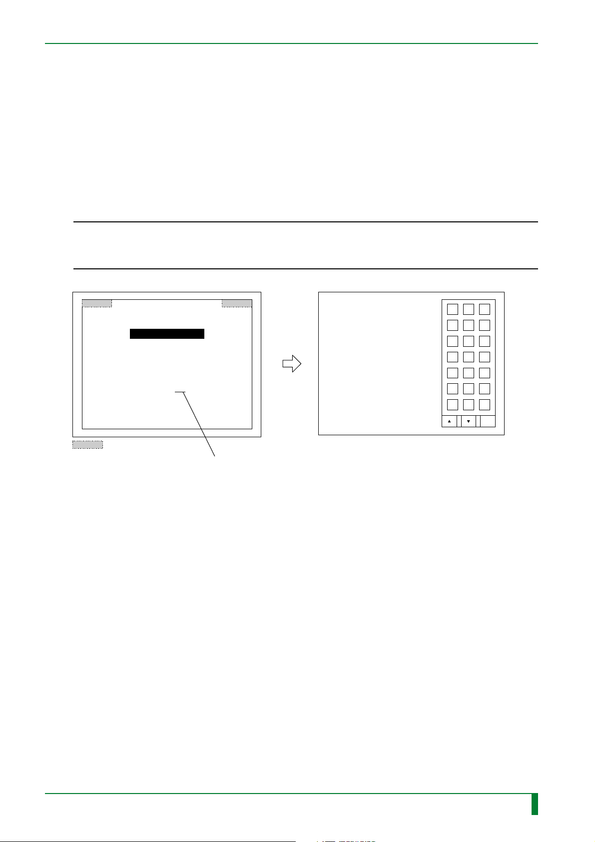
(3) Image Processing Parameter Adjustment
A PC running Windows 95 may be connected on-line to the machine to rewrite various
image processing parameters.
Rewriting of image processing parameters that require repeated setting changes can be
implemented efficiently by registering several setting patterns in the PC, for e xample.
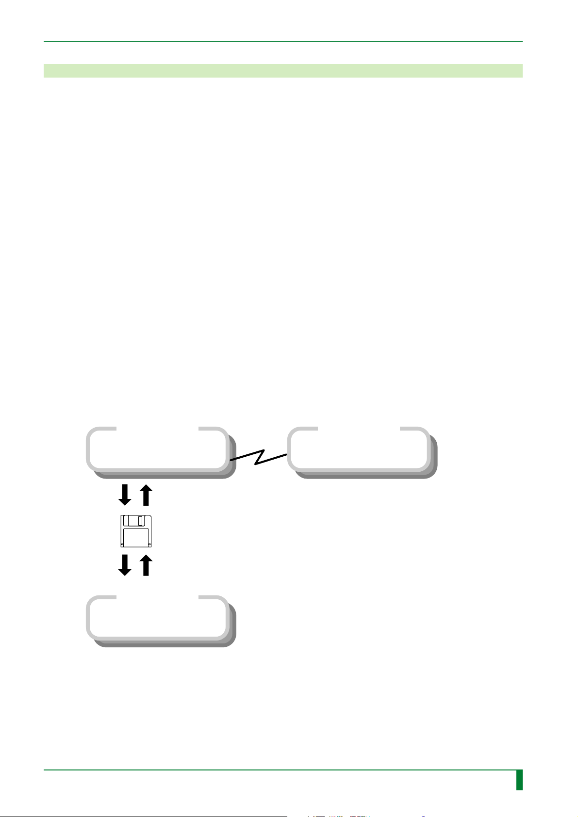
CR-IR347
• Maintenance Utility
3.5-inch FD
1.44MB DOS formatted
• Image Processing Parameter
Online PC
Adjustment
Online PC
• Configuration Setting
009-058-02
08.30.2001 FM3142
CR-IR347
Service Manual
FR1H3001.EPS
MU - 2

BLANK PAGE
MU - 3
009-058-02
08.30.2001 FM3142
CR-IR347
Service Manual
MU - 3
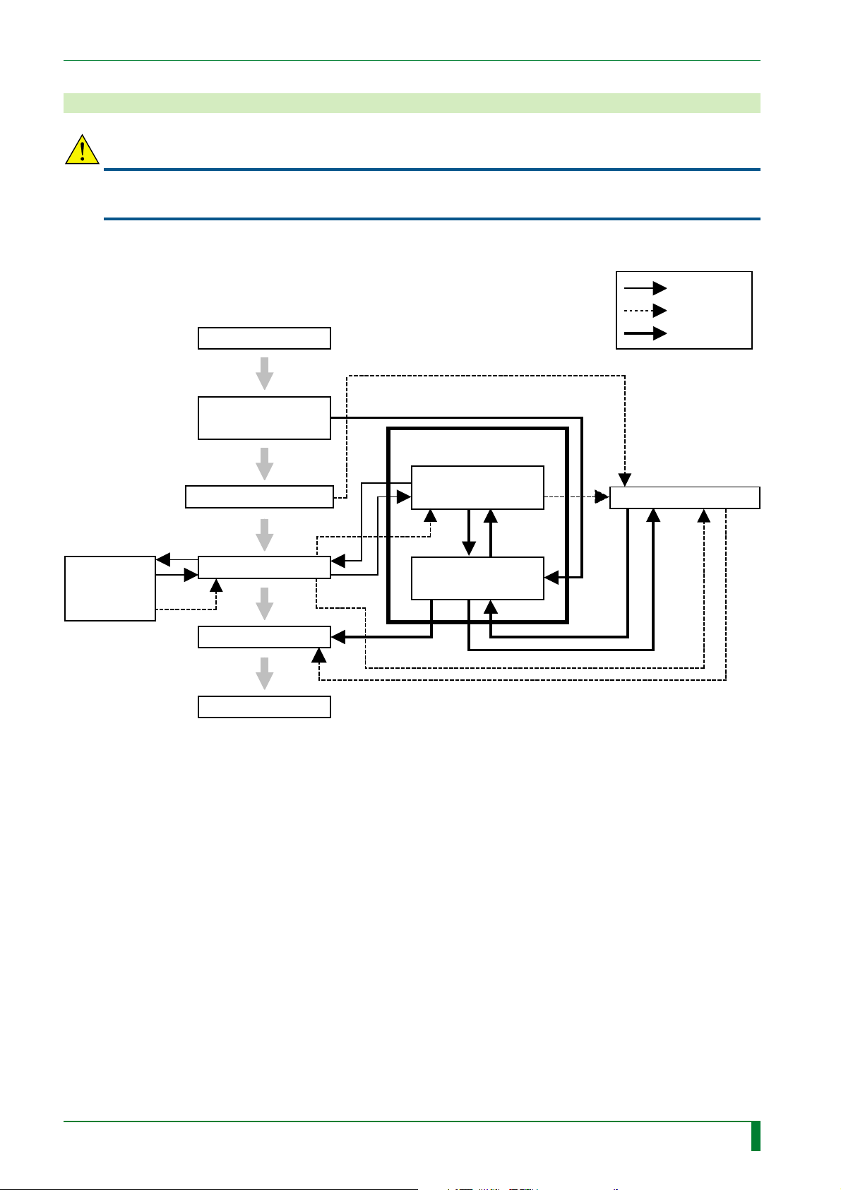
2. Mode T ransitions
CAUTION
If the circuit breaker power supply is turned OFF while data is being written to a floppy disk (FD)
or the hard disk drive (HDD), the data, FDD, or the HDD itself may be damaged.
Power ON
Software version
display (5 sec)
Service utility
MU - 4
Normal
Abnormal
Special touch
IDT utility mode
Initialization process mode
Routine process mode
End process mode
Power OFF
User utility mode
Maintenance
utility mode
Abnormality process mode
FR7H4043.EPS
009-058-02
08.30.2001 FM3142
CR-IR347
Service Manual
MU - 4

(1) Initialization process mode
Condition where initialization and self-diagnostics processing is performed during power-ON.
(2) Routine process mode
Routine, ready condition.
(3) Abnormality process mode
Condition where an error is displayed upon occurrence of an abnormality.
(4) User utility mode (U-Utility)
Condition where the user is performing routine maintenance procedures.
(5) Maintenance utility mode (M-Utility)
MU - 5
Condition where the serviceman is performing troubleshooting or maintenance procedures.
(6) End process mode
Condition where the process is quitted to make the machine inoperative.
009-058-02
08.30.2001 FM3142
CR-IR347
Service Manual
MU - 5

3. U-Utility (User Utility)
(1) Functions of U-Utility
The User-Utility provides utility functions intended for use by both a general user and a
service engineer.
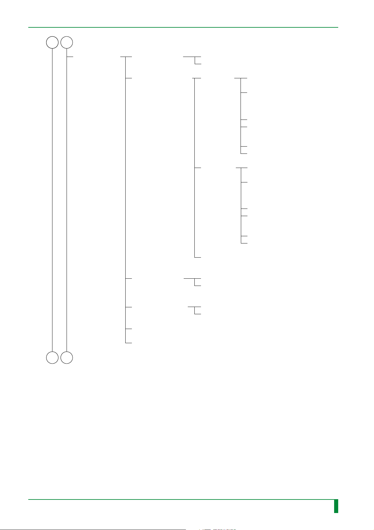
(2) U-Utility tree
U-Utility
MU - 6
DELETE WAITING IMAGES
REOUTPUT IMAGE
SET DATE/TIME
SET CLICK SOUND
ADJUST TOUCH POINT
SELECT IMAGE OUTPUT DESTINATION
DISPLAY CRT TEST PATTERN
OUTPUT MULTI-FRAME IMAGE
DELETE PRINTING IMAGE(S)
DELETE FILING IMAGE(S)
DELETE OTHER IMAGE(S)
DELETE LOCKED IMAGE(S)
DELETE EXCEPT LOCKED IMAGE(S)
ON
OFF
PRINTER
DISPLAY
FILING
SAVE/LOAD PARAMETERS
009-058-03
08.30.2002 FM3476
CR-IR347
Service Manual
SAVE IMAGE PROCESSING PARAMETERS
LOAD IMAGE PROCESSING PARAMETERS
SAVE MENU PARAMETERS
LOAD MENU PARAMETERS
FR7H4044.EPS
MU - 6
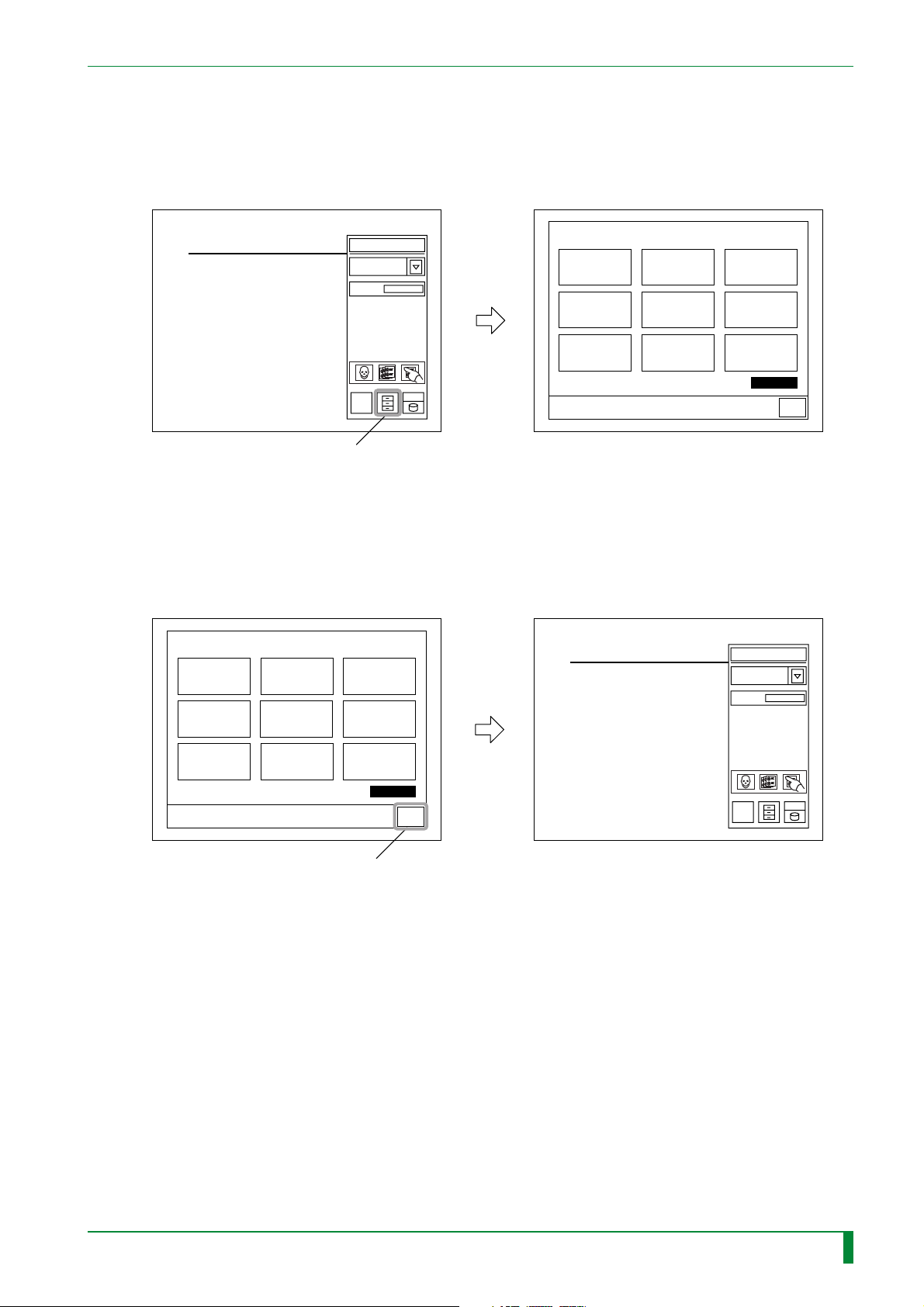
(3) U-Utility operation
■ Starting the U-Utility
Touch the U-Utility button.
MU - 7
U-Utility button
■ Quitting the U-Utility
Touch the “QUIT” button.
DELETE
WAITING IMAGES
REOUTPUT
IMAGE
Read
SET
DATE/TIME
DELETE
WAITING IMAGES
SET CLICK SOUND
DISPLAY
CRT TEST PATTERN
REOUTPUT
IMAGE
ADJUST
TOUCH POINT
OUTPUT
MULTI-FRAME
IMAGE
SET
DATE/TIME
SELECT IMAGE
OUTPUT DESTINA.
SAVE / LOAD
PARAMETERS
XXXXXX
0
UTILITY
QUIT
FR7H4046.EPS
Read
SET CLICK SOUND
DISPLAY
CRT TEST PATTERN
ADJUST
TOUCH POINT
OUTPUT
MULTI-FRAME
IMAGE
UTILITY
QUIT button
SELECT IMAGE
OUTPUT DESTINA.
SAVE / LOAD
PARAMETERS
XXXXXX
QUIT
0
FR7H4047.EPS
009-058-03
08.30.2002 FM3476
CR-IR347
Service Manual
MU - 7

(4) U-Utility commands
■ DELETE WAITING IMAGES
Deletes images that have not been outputted.
● DELETE PRINTING IMAGE(S)
Deletes all images awaiting output to LP.
● DELETE FILING IMAGE(S)
Deletes all images awaiting output to ODF.
● DELETE OTHER IMAGE(S)
Deletes all images awaiting output to HI-C or image monitor.
● DELETE LOCKED IMAGE(S)
Deletes all locked images awaiting output.
● DELETE EXCEPT LOCKED IMAGE(S)
Deletes all images - other than locked ones - awaiting output.
■ REOUTPUT IMAGE
MU - 8
Reoutputs images.
■ SET DATE/TIME
Sets the date and time.
■ SET CLICK SOUND
Set the click sound to ON or OFF.
■ ADJUST TOUCH POINT
Adjusts the touch point on the touch panel.
■ SELECT OUTPUT DESTINATION
Selects the image output destination.
■ DISPLAY CRT TEST PATTERN
Displays the CRT test pattern.
■ OUTPUT MULTI-FRAME IMAGE
Generates forced-output of images.
■ SAVE/LOAD PARAMETERS
● SAVE IMAGE PROCESSING PARAMETERS
Saves image processing parameters to the FD.
● LOAD IMAGE PROCESSING PARAMETERS
Loads image processing parameters from the FD.
● SAVE MENU PARAMETERS
Saves menu parameters to the FD.
● LOAD MENU PARAMETERS
Loads menu parameters to the FD.
009-058-03
08.30.2002 FM3476
CR-IR347
Service Manual
MU - 8

BLANK PAGE
MU - 9
009-058-02
08.30.2001 FM3142
CR-IR347
Service Manual
MU - 9
4. M-Utility (Maintenance Utility)
(1) Functions of M-Utility
The M-Utility provides utility functions intended exclusiv ely for use by a service engineer.
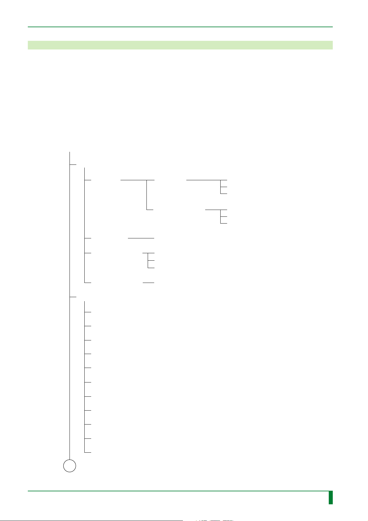
(2) M-Utility tree
■ Routine Operation
M-Utility
[ 1 ] ERROR LOG UTILITY
MU - 10
[ 1-1 ] LIST
[ 1-2 ] CLEAR
[ 1-3 ] SAVE TO FD
[ 1-4 ] SAVE TO HD
[ 1-1-1 ] ALL
[ 1-1-2 ] SUMMARY
1.ERROR LOG
[ 1-3-1 ] ERROR LOG
[ 1-3-2 ] TRACE DATA
[ 1-3-3 ] IOT DATA
1.ERROR LOG
[ 2 ] CONFIGURATION SETTING
[ 2-1 ] SYSTEM
[ 2-2 ] PRINT
[ 2-3 ] REMOTE SWITCH
[ 2-4 ] EQUIPMENT
1.ERROR
2.WARNING
3.BOTH
1.ERROR
2.WARNING
3.BOTH
009-058-02
08.30.2001 FM3142
A1
[ 2-5 ] LOCAL INTERFACE
[ 2-6 ] NETWORK HOST INTERFACE
[ 2-7 ] HOSTS ADDRESS
[ 2-8 ] DISTRIBUTION
[ 2-9 ] ROUTING
[ 2-10 ] NETMASKS
[ 2-11 ] DICOM
CR-IR347
Service Manual
FR7H4010.EPS
MU - 10

A1
[ 3 ] TEST MODE
[ 3-1 ] ROUTINE
MU - 11
[ 3-2 ] AUTO MODE
[ 3-2-1 ] READING & ERASURE
[ 3-2-2 ] PRIMARY ERASURE
[ 3-2-3 ] SECONDARY ERASURE
[ 4 ] ELECTRICAL UTILITY
[ 4-1 ] ERASURE LAMP TEST
[ 4-2 ] IMAGE MEMORY TEST
[ 4-3 ] DSP TEST
[ 4-4 ] LAN
[ 4-5 ] HDD
[ 4-6 ] FDD
[ 4-4-1 ] ETHERNET MAC ADDRESS
[ 4-4-2 ] PING
[ 4-4-3 ] CPU90F DMA: This menu shall not be used.
[ 4-5-1 ] WRITE-READ VERIFY
[ 4-6-1 ] WRITE-READ VERIFY
[ 5 ] SCANNER UTILITY
[ 5-1 ] INITIALIZE
[ 5-2 ] POLYGON
[ 5-2-1 ] OFF
[ 5-2-2 ] ON
A2 B1
[ 5-3 ] LASER
[ 5-4 ] HV
[ 5-5 ] HV DATA
[ 5-6 ] FORMAT
[ 5-3-1 ] OFF
[ 5-3-2 ] ON
[ 5-4-1 ] OFF
[ 5-4-2 ] ON
[ 5-5-1 ] FRONT
[ 5-5-2 ] BACK
[ 5-6-1 ] DEFAULT
[ 5-6-2 ] FREQ ADJUST
[ 5-6-3 ] PIXEL ADJUST
1.PIXEL AND FREQ
2.PIXEL ONLY
3.FREQ ONLY
FR7H4011.EPS
009-058-02
08.30.2001 FM3142
CR-IR347
Service Manual
MU - 11
A1A2 B1
MU - 12
[ 5-7 ] SHADING /
SENSITIVITY
[ 5-7-1 ] REC MODE
[ 5-7-2 ] CALCULATION
1.ST
2.HR
[ 5-7-2-1 ] ST
[ 5-7-2-2 ] HR
1.SHADING, POLYGON
AND SENSITIVITY
2.SHADING, POLYGON
AND SENSITIVITY
FOR BAD CONDITION
: Shall not be used in the market.
3.SHADING AND POLYGON
4.SHADING AND POLYGON
FOR BAD CONDITION
: Shall not be used in the market.
5.POLYGON ONLY
6.SENSITIVITY ONLY
1.SHADING, POLYGON
AND SENSITIVITY
2.SHADING, POLYGON
AND SENSITIVITY
FOR BAD CONDITION
: Shall not be used in the market.
3.SHADING AND POLYGON
4.SHADING AND POLYGON
FOR BAD CONDITION
: Shall not be used in the market.
5.POLYGON ONLY
6.SENSITIVITY ONLY
A3 B2
[ 5-7-2-3 ] HR(FOR MANUFACTURING)
: Shall not be used in the market.
[ 5-7-3 ] SHADING /
POLYGON
CORRECTION
[ 5-7-4 ] SENSITIVITY
DATA
[ 5-7-5 ] HV DAT: Shall not be used in the market.
[ 5-7-6 ] PMT DATA: Shall not be used in the market.
1.OFF
2.ON
1.ST
2.HR
FR7H4013.EPS
009-058-03
08.30.2002 FM3476
CR-IR347
Service Manual
MU - 12

A3 B2
MU - 13
[ 5-8 ] DATA
MANAGEMENT
[ 5-9 ] DIAGNOSTIC
[ 5-10 ] VIRTUAL
IMAGE
[ 5-11 ] BOTH SIDES
ADDITIONAL
[ 5-8-1 ] SAVE SHADING
[ 5-8-2 ] SAVE SENSITIVITY DATA
[ 5-8-3 ] SAVE FORMAT DATA
[ 5-8-4 ] DISPLAY DATA
[ 5-8-5 ] LOAD FROM FD
[ 5-8-6 ] SAVE TO FD
[ 5-10-1 ] LIGHT
[ 5-10-2 ] LOG AMP
[ 5-10-3 ] SCN08 INPUT
[ 5-10-4 ] ROUTINE
[ 5-11-1 ] FRONT ONLY
[ 5-11-2 ] BACK ONLY
[ 5-11-3 ] ROUTINE
[ 6 ] MECHANICAL UTILITY
AND POLYGON DATA
1.SHADING / POLYGON
2.SENSITIVITY
1.EQUIVALENT
TO 0.2-0.3 [ mR ]
2.EQUIVALENT
TO 2-3 [ mR ]
A4
[ 6-1 ] INITIALIZE: Displayed during initialization or upon occurrence of a serious error.
[ 6-2 ] MOTOR
[ 6-3 ] ACTUATOR
[ 6-4 ] SENSOR
B3
[ 6-2-1 ] NUMBER
[ 6-2-2 ] PARAMETER
[ 6-2-3 ] DRIVE
[ 6-2-4 ] STOP
[ 6-3-1 ] NUMBER
[ 6-3-2 ] DRIVE
[ 6-3-3 ] STOP
[ 6-4-1 ] NUMBER
[ 6-4-2 ] MONITOR
[ 6-4-3 ] MONITOR ALL
FR7H4014.EPS
009-058-02
08.30.2001 FM3142
CR-IR347
Service Manual
MU - 13

A4 B3
MU - 14
[ 6-5 ] UNIT
[ 6-5-1 ] IP FEED/
LOAD UNIT
[ 6-5-1-1 ] ARM HOME
POSITION
[ 6-5-1-2 ] FEED/LOAD
[ 6-5-2 ] UP/DOWN UNIT: Does not function.
[ 6-5-3 ] SIDE-POSITIONING
GRIP
[ 6-5-3-1 ] HOME POSITION
[ 6-5-3-2 ] GRIP
[ 6-5-3-3 ] RELEASE
[ 6-5-4 ] SIDE-POSITIONING
UNIT
[ 6-5-4-1 ] HOME POSITION
[ 6-5-4-2 ] ACTUATION
[ 6-5-5 ] AFTER-READING GRIP: Does not function.
[ 6-5-6 ] DRIVING GRIP [ 6-5-6-1 ] GRIP
[ 6-5-6-2 ] RELEASE
1.NORMAL
MODE
2.STEP
MODE
1.NORMAL
2.STEP
1.HIGH
2.LOW
1.ST
2.HR
A5
[ 6-5-6-3 ] D/A DATA
[ 6-5-7 ] DRIVEN GRIP [ 6-5-7-1 ] GRIP
[ 6-5-7-2 ] RELEASE
[ 6-5-7-3 ] D/A DATA
[ 6-5-8 ] MIRROR UP/DOWN [ 6-5-8-1 ] UP
[ 6-5-8-2 ] DOWN
[ 6-5-9 ] CLEANING GUIDE [ 6-5-9-1 ] HOME POSITION
[ 6-5-9-2 ] GRIP
[ 6-5-9-3 ] RELEASE
1.HIGH
2.LOW
1.ST
2.HR
FR7H4015.EPS
009-058-02
08.30.2001 FM3142
CR-IR347
Service Manual
MU - 14

[ 7 ] FILE UTILITY
[ 7-1 ] FORMAT FD
[ 7-2 ] FORMAT IMAGE PARTITION
[ 7-3 ] BACKUP
[ 7-3-1 ] SCANNER DATA
[ 7-3-2 ] CONFIGURATION DATA
[ 7-3-3 ] NETWORK DATA
[ 7-3-4 ] IMAGE PROCESSING DATA
[ 7-3-5 ] CSL MENU DATA
[ 7-3-6 ] EDR PROCESSING DATA
[ 7-4-5 ] CSL MENU DATA
[ 7-4-6 ] EDR PROCESSING DATA
[ 7-4 ] RESTORE
[ 7-4-1 ] SCANNER DATA
[ 7-4-2 ] CONFIGURATION DATA
[ 7-4-3 ] NETWORK DATA
[ 7-4-4 ] IMAGE PROCESSING DATA
[ 7-5 ] EDR DATA
[ 7-5-1 ] PARAMETER ONLY(SAVE TO FD)
[ 7-5-2 ] FULL(SAVE TO FD)
FR7H4016.EPS
[ 8 ] BACKUP MEMORY
[ 9 ] HV ON/OFF
1.CLEAR
[ 7-6 ] PREVIOUS SYSTEM SOFTWARE
[ 7-7 ] EXECUTION
A5
[ 10 ] MENU SETTING This mode shall not be used.
[ 11 ] SYSTEM UTILITY
1.SETTING SYSTEM CONVEYANCES COUNTS
[ 7-5-4 ] FULL(SAVE TO HD) : This menu shall not be used.
[ 7-5-3 ] PARAMETER ONLY(SAVE TO HD) : This menu shall not be used.
[ 7-5-5 ] DELETE EDR BACKUP FILES ON HD : This menu shall not be used.
MU - 15
009-058-02
08.30.2001 FM3142
CR-IR347
Service Manual
MU - 15
(3) M-Utility operation
C R - I R 3 4 7
■ Starting the M-Utility (Three Scenarios)
● Starting the M-Utility from the initialization process mode
After the machine is powered ON, the initialization screen appears, and subsequently
a software version number is displayed for about five seconds. During that period of
time, touch the upper left-hand corner of the operation panel, and then, within two
seconds, the upper right-hand corner.
◆
NOTE
After the display of the software version number ends, the operation panel does not respond at
all even if you touch it. In such an instance, perform a reset and wait until the software version
number appears on the screen, or enter the routine process mode and then start the M-Utility.
◆
MU - 16
C R - I R 3 4 7
Copyright (c) 2000 Fuji Photo Film Co.,Ltd
Software ID
Software Version
: 114Y5437003
: A00
: Location to be touched
Software version number
1. ERROR LOG UTILITY
2. CONFIGURATION SETTING
3. ELECTRICAL UTILITY
4. SCANNER UTILITY
5. MECHANICAL UTILITY
6. FILE UTILITY
7. BACKUP MEMORY
8. HV ON(OFF)
9. MENU SETTING
10. SYSTEM UTILITY
ABC
DEF
789
456
123
0.SP
DEL BS ENT
Caps
FR7H4048.EPS
009-058-02
08.30.2001 FM3142
CR-IR347
Service Manual
MU - 16
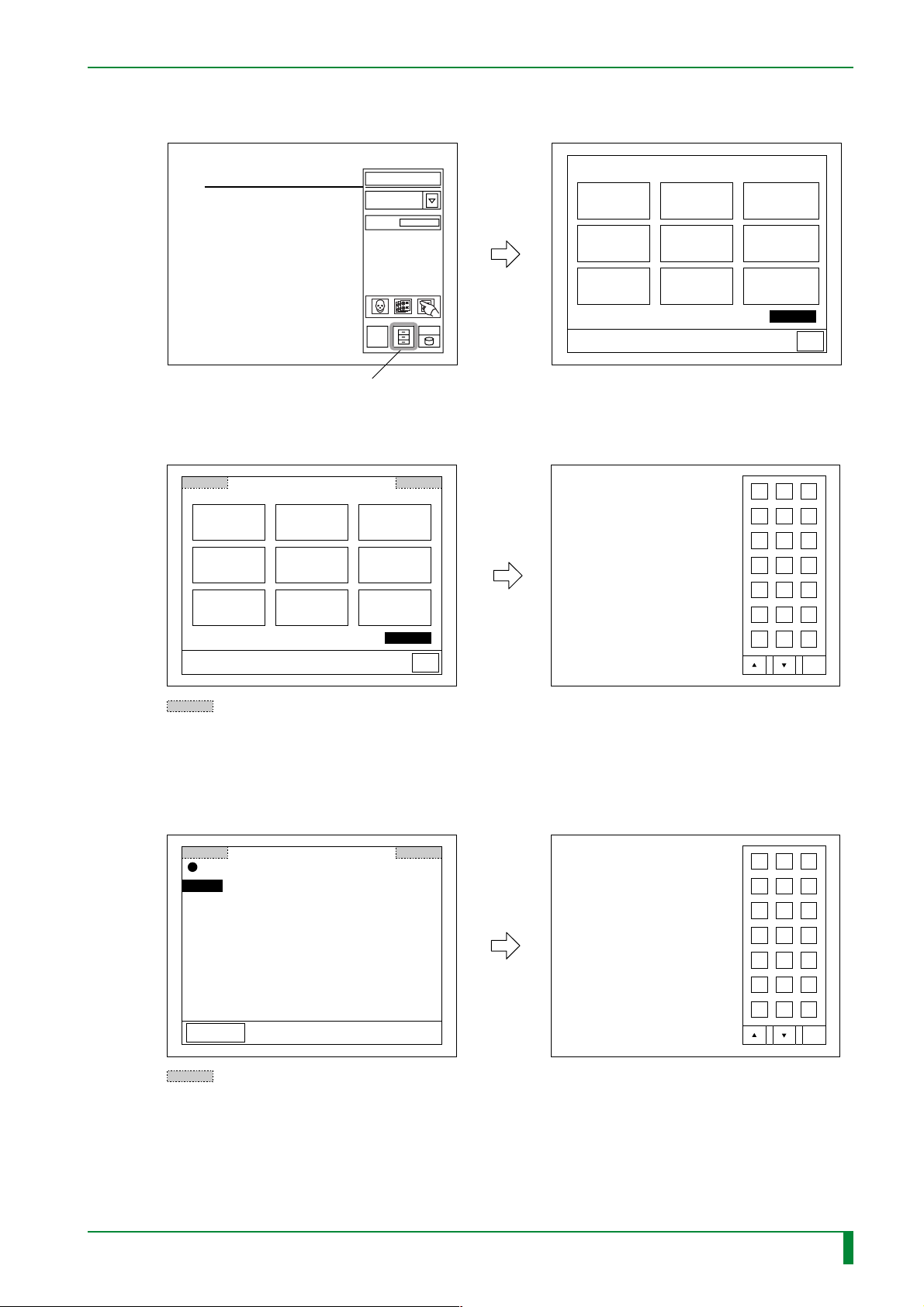
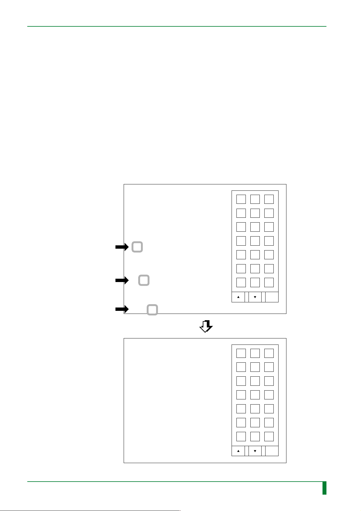
● Starting the M-Utility from the routine process mode (routine mode)
(1) Press the U-Utility button.
MU - 17
Read
DELETE
WAITING IMAGES
SET CLICK SOUND
DISPLAY
CRT TEST PATTERN
REOUTPUT
IMAGE
ADJUST
TOUCH POINT
OUTPUT
MULTI-FRAME
IMAGE
SET
DATE/TIME
SELECT IMAGE
OUTPUT DESTINA.
SAVE / LOAD
PARAMETERS
XXXXXX
0
U-Utility button
Utility
Return
FR7H4049.EPS
(2) Touch the upper left-hand corner of the touch panel, and then, within two seconds,
touch the upper right-hand corner.
DELETE
WAITING IMAGES
SET CLICK SOUND
DISPLAY
CRT TEST PATTERN
REOUTPUT
IMAGE
ADJUST
TOUCH POINT
OUTPUT
OUTPUT MULTI-
MULTI-FRAME
FRAME IMAGE
IMAGE
Utility
SET
DATE/TIME
SELECT IMAGE
OUTPUT DESTINA.
SAVE / LOAD
PARAMETERS
XXXXXX
Return
0. QUIT
1. ERROR LOG UTILITY
2. CONFIGURATION SETTING
3. TEST MODE
4. ELECTRICAL UTILITY
5. SCANNER UTILITY
6. MECHANICAL UTILITY
7. FILE UTILITY
8. BACKUP MEMORY
9. HV ON(OFF)
10. MENU SETTING
11. SYSTEM UTILITY
ABC
DEF
789
456
123
0.SP
DEL BS ENT
Caps
: Location to be touched
● Starting the M-Utility from the abnormality process mode
Touch the upper left-hand corner of the operation panel, and then, within two seconds,
touch the upper right-hand corner.
Call maintenance personnel.
IP switch back conveyance error.
03D2
Stop alarm
System down
: Area to be touched
1. ERROR LOG UTILITY
2. CONFIGURATION SETTING
3. ELECTRICAL UTILITY
4. SCANNER UTILITY
5. MECHANICAL UTILITY
6. FILE UTILITY
7. BACKUP MEMORY
8. HV ON(OFF)
9. MENU SETTING
10. SYSTEM UTILITY
FR7H4050.EPS
ABC
DEF
789
456
123
0.SP
DEL BS ENT
Caps
FR7H4051.EPS
009-058-03
08.30.2002 FM3476
CR-IR347
Service Manual
MU - 17

■ Exiting M-Utility
◆
NOTE
If M-Utility is entered during the initialization sequence, “0. QUIT” does not appear. Thus,
after quitting M-Utility, the machine should be reset.
(1) While the M-Utility main menu is displayed, select “0. QUIT”.
(2) Press the reset button.
◆
MU - 18
009-058-02
08.30.2001 FM3142
CR-IR347
Service Manual
MU - 18
(4) Common Operating Procedures for M-Utility
■ Selecting a Menu (Two Scenarios)
● While the “>” cursor is displayed, enter a menu number.
The system displays the lower-level menu or immediately executes the designated
menu and shows the result.
● Automatic menu selection upon a menu selection
When you select a menu, the system automatically selects the associated menu.
Example) The sensor list menu appears.
Select “6. MECHANICAL UTILITY”, “3. SENSOR”, and “2.
MONITOR” in sequence.
0. QUIT
1. ERROR LOG UTILITY
#1 [Enter/ENT]
#2 [Enter/ENT]
#3 [Enter/ENT]
2. CONFIGURATION SETTING
3. TEST MODE
4. ELECTRICAL UTILITY
5. SCANNER UTILITY
6. MECHANICAL UTILITY
7. FILE UTILITY
8. BACKUP MEMORY
9. HV OFF
10. MENU SETTING
11. SYSTEM UTILITY
> 6
0.QUIT
1.MOTOR
2.ACTUATOR
3.SENSOR
4.UNIT
MU > 3
0.QUIT
1.NUMBER
2.MONITOR
3.MONITOR ALL
MU:SEN > 2
ABC
DEF
789
456
123
0.SP
DEL BS ENT
MU - 19
Caps
MU:SEN > 2
1:SK1 2:SK2 3:SK3
21:SL4 22:SL5 23:SM1 25:SN1
26:SN2 27:SN3 28:SN4
INPUT THE NUMBER OF SENSOR
1 - 35 : 3
SK3 ----> Close
SK3 ----> Open
SK3 ----> Close
0:QUIT
0.QUIT
1.NUMBER
2.MONITOR
3.MONITOR ALL
MU:SEN >
18:SL1 19:SL2
33:SZ2 34:SZ3 35:SZ4
ABC
DEF
789
456
123
0.SP
DEL BS ENT
Caps
FR7H4007.EPS
009-058-02
08.30.2001 FM3142
CR-IR347
Service Manual
MU - 19
■ Quitting a Menu
● Selecting “QUIT”
When you select “QUIT” on a menu, one of the following results follows.
❍ When a menu item is displayed, the system returns to the upper-level menu.
❍ When the main menu is displayed, the system exits M-Utility and switches to U-
Utility.
❍ The system stops the current menu execution (operation).
❍ The system returns to the upper-level menu while continuing with the current menu
ex ecution (operation).
● Selecting “STOP”
Select “STOP”, the actuator or motor operation (DRIVE) ends.
Example: “3. STOP” is selected.
#1 [Enter/ENT]
#2 [Enter/ENT]
#3 [Enter/ENT]
When you select “6. MECHANICAL UTILITY”, “3. SENSOR”, and “2.
MONITOR” in sequence
0. QUIT
1. ERROR LOG UTILITY
2. CONFIGURATION SETTING
3. TEST MODE
4. ELECTRICAL UTILITY
5. SCANNER UTILITY
6. MECHANICAL UTILITY
7. FILE UTILITY
8. BACKUP MEMORY
9. HV OFF
10. MENU SETTING
11. SYSTEM UTILITY
> 6
0.QUIT
1.MOTOR
2.ACTUATOR
3.SENSOR
4.UNIT
MU > 2
0.QUIT
1.NUMBER
2.DRIVE
3.STOP
MU:ACT > 3
ABC
DEF
789
456
123
0.SP
DEL BS ENT
Caps
MU - 20
009-058-02
08.30.2001 FM3142
MU:ACT > 3
1:SOLK1 5:PL1
6:SVL1 9:LAMP STB 10:LAMP ON
11:FFM 12:MZ4
INPUT THE NUMBER OF SENSOR
1 - 12 : 1
0.QUIT
1.NUMBER
2.DRIVE
3.STOP
MU:ACT >
CR-IR347
Service Manual
ABC
DEF
789
456
123
0.SP
DEL BS ENT
Caps
FR7H4008.EPS
MU - 20

■ Entering a Numerical Value
● Displaying Virtural Keyboard for Entry
Three types of virtual keyboards are available; by touching the ▲ or ▼ key, one of the
three virtual keyboards can be selected. Also, by touching the [Caps] key, the caps
mode can be toggled to the lower-cap display corresponding to the three types of
virtual keyboards.
0. QUIT
1. ERROR LOG UTILITY
2. CONFIGURATION SETTING
3. TEST MODE
4. ELECTRICAL UTILITY
5. SCANNER UTILITY
6. MECHANICAL UTILITY
7. FILE UTILITY
8. BACKUP MEMORY
9. HV OFF
10. MENU SETTING
11. SYSTEM UTILITY
> 3
0.QUIT
1.ROUTINE
2.AUTO MODE
TM > 2
MU - 21
ABC
DEF
789
456
123
0.SP
0.QUIT
1.READING & ERASURE
2.PRIMARY ERASURE
3.SECONDARY ERASURE
TM:AM > 2
INPUT THE NUMBER OF CONVEYANCE
0 - 99999 :
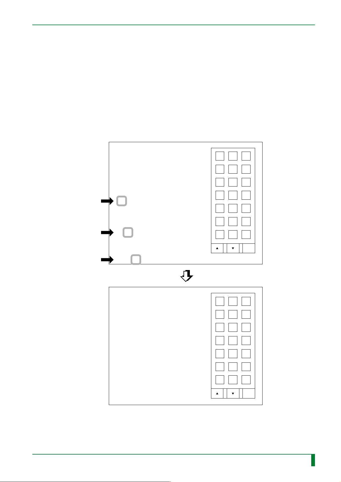
● Correcting a value entry
You can correct a value entry with the [DEL] or [BS] key.
• [DEL] key: Each time you touch this key, it erases the character above the cursor.
• [BS] key: Each time you touch this key, it erases the character preceding
(positionedto the left of) the cursor position.
Example) Changing the numerical entry from 9801 to 9901
1) Touch the operation panel to position the cursor under “0”.
2) Touch the [BS] key once to delete “8”.
3) Touch 9.
DEL BS ENT
Caps
FR7H4009.EPS
009-058-02
08.30.2001 FM3142
CR-IR347
Service Manual
MU - 21

■ Menu Hierarchy of M-Utility in Initialization Sequence or in Serious Error
During the initialization sequence or upon occurrence of serious error (i.e., when the mode
switches from the error message displayed status to M-Utility), the basic menu structure is
the same as in normal operation, except some of the menus are omitted.
For your reference, the upper menu hierarchy is shown below.
● Menu Hierarchy in Initialization Sequence or in Serious Error
◆
NOTE
◆
Before using the MECHANICAL UTILITY in initialization sequence or in serious error, be
sure to run “1. INITIALIZE” to initialize the motors, actuators, and sensors.
MAINTENANCE UTILITY
MU - 22
0.QUIT
(not displayed during initialization)
1.ERROR LOG UTILITY
2.CONFIGURATION SETTING
3.ELECTRICAL UTILITY
0.QUIT
1.IMAGE MEMORY TEST
2.LAN
3.HDD
4.FDD
4.SCANNER UTILITY
0.QUIT
1.INITIALIZE
2.POLYGON
3.LASER
4.HV
5.HV DATA
6.SHADING / SENSITIVITY
5.MECHANICAL UTILITY
0.QUIT
1.INITIALIZE
2.MOTOR
3.ACTUATOR
4.SENSOR
5.UNIT
A1
FR7H4018.EPS
009-058-02
08.30.2001 FM3142
CR-IR347
Service Manual
MU - 22
 Loading...