

Siemens 9410RC, 9410DC, 9410TC User Manual
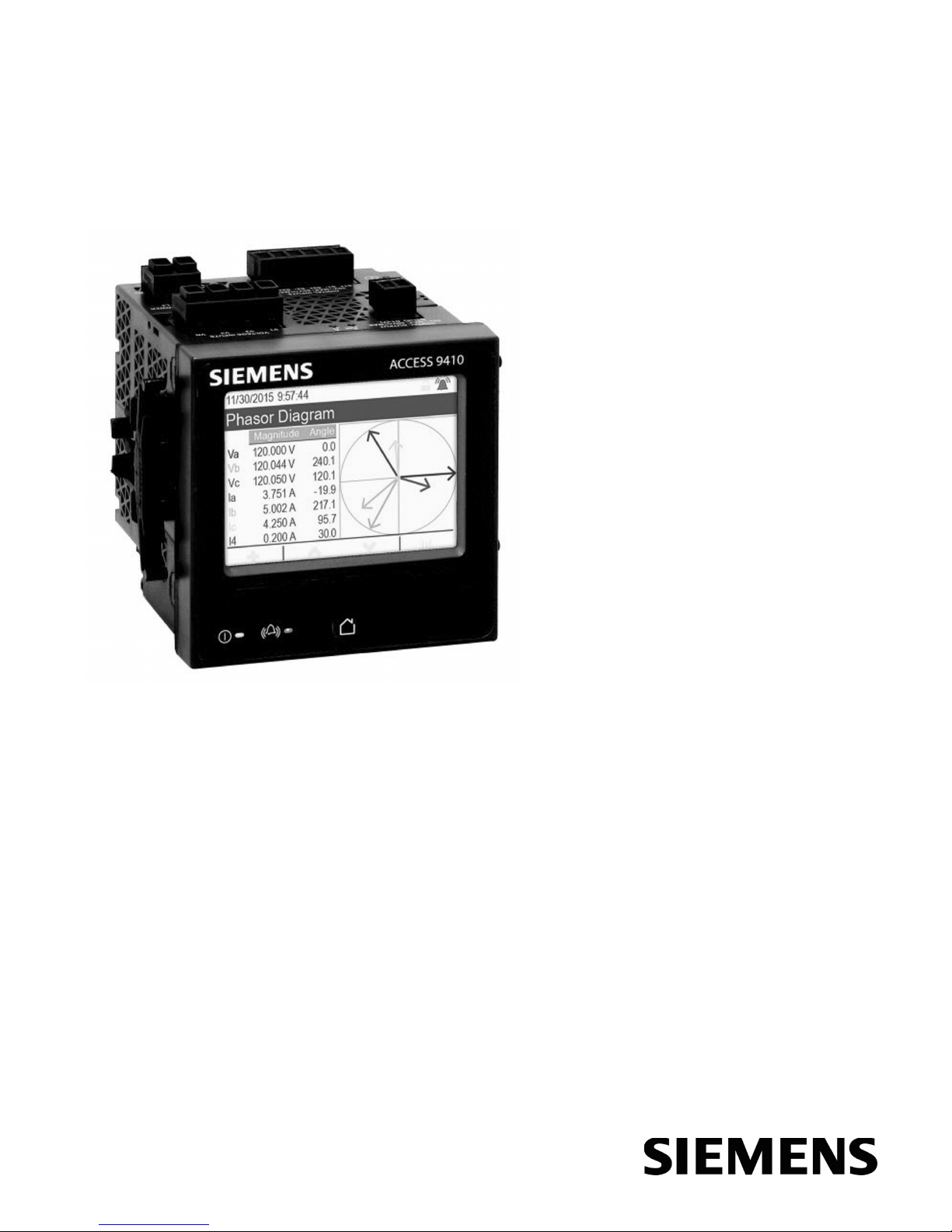
9410 series
User manual
7EN05-0336-01
09/2015
www.usa.siemens.com/pds
9410 series
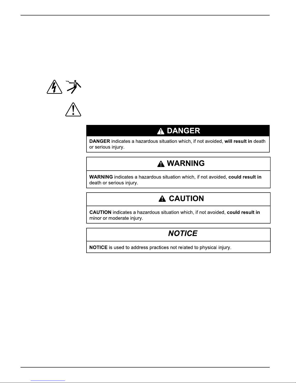
DANGER
DANGER indicates a haz ardous situation which, if not avoided, will result in death
or serious injury.
WARNING
WARNING indicates a ha zardous situation which, if not avoided, could result in
death or serious injury.
CAUTION
CAUTION indicates a haz ardous situation which, if not avoided, could result in
minor or moderate injury.
NOTICE
NOTICE is used to addre ss practices not related to physical injury.
Safety information
Important information
Read these instructions carefully and look at the equipment to become familiar with the
device before trying to install, operate, service or maintain it. The following special
messages may appear throughout this bulletin or on the equipment to warn of potential
hazards or to call attention to information that clarifies or simplifies a procedure.
The addition of either symbol to a “Danger” or “Warning” safety label indicates that an
electrical hazard exists which will result in personal injury if the instructions are not
followed.
This is the safety alert symbol. It is used to alert you to potential personal injury
hazards. Obey all safety messages that follow this symbol to avoid possible injury or
death.
Please note
Electrical equipment should be installed, operated, serviced and maintained only by
qualified personnel. No responsibility is assumed by Siemens Industry for any
consequences arising out of the use of this material. A qualified person is one who has
skills and knowledge related to the construction, installation, and operation of electrical
equipment and has received safety training to recognize and avoid the hazards
involved.
2 7EN05-0336-01

Notices
FCC
9410 series
This equipment has been tested and found to comply with the limits for a Class B
digital device, pursuant to part 15 of the FCC rules. These limits are designed to
provide reasonable protection against harmful interference in a residential installation.
This equipment generates, uses, and can radiate radio frequency energy and, if not
installed and used in accordance with the instructions, may cause harmful interference
to radio communications. However, there is no guarantee that the interference will not
occur in a particular installation. If this equipment does cause harmful interference to
radio or television reception, which can be determined by turning the equipment off
and on, the user is encouraged to try to correct the interference by one or more of the
following measures:
• Reorient or relocate the receiving antenna.
• Increase the separation between the equipment and receiver.
• Connect the equipment to an outlet on a circuit different from that to which the
receiver is connected.
• Consult the dealer or an experienced radio/TV technician for help.
The user is cautioned that any changes or modifications not expressly approved by
Siemens Industry could void the user’s authority to operate the equipment.
This digital apparatus complies with CAN ICES-3 (B) /NMB-3(B).
About this manual
This manual discusses features of the 9410 series power meter and provides
installation and configuration instructions.
Throughout the manual, the term “meter” refers to all models of the 9410. All
differences between the models, such as a feature specific to one model, are indicated
with the appropriate model number or description.
This manual assumes you have an understanding of power metering and are familiar
with the equipment and power system in which your meter is installed.
This manual does not provide configuration information for advanced features where
an expert user would perform advanced configuration. It also does not include
instructions on how to incorporate meter data or perform meter configuration using
energy management systems or software, other than ION Setup. ION Setup is a free
configuration tool available for download from www.usa.siemens.com/pds.
Please contact your local Siemens Industry representative to learn what additional
training opportunities are available regarding the 9410 meter.
The most up-to-date documentation about your meter is available for download from
www.usa.siemens.com/pds.
Related documents
Document Number
9410DC installation sheet NVE23944
9410TC installation sheet NVE23945
ION Reference 70005-0290
ION device template reference
7EN05-0336-01 3
—

9410 series
4 7EN05-0336-01

Table of Contents
Safety precautions............................................................................................9
Meter overview................................................................................................10
9410 overview ...............................................................................................10
Your meter in an energy management system ..................................................10
Measured parameters .................................................................................... 11
Localization ...................................................................................................13
Data display and analysis tools ....................................................................... 13
Supported protocols .......................................................................................13
ION Setup device configuration tool .................................................................14
Meter types.................................................................................................... 14
Mounting adaptors ......................................................................................... 14
Terminal covers..............................................................................................14
Replacement hardware................................................................................... 15
Basic setup ...................................................................................................... 16
Default values for commissioning .................................................................... 16
Meter setup ................................................................................................... 16
Minimum configuration requirements for basic metering ....................................17
Lost user access ............................................................................................ 17
9410 series
Volts mode ...............................................................................................16
PT/CT setup ............................................................................................. 16
Voltage polarity setup ...............................................................................17
Current polarity setup................................................................................17
Nominal values ........................................................................................17
Hardware reference .......................................................................................18
Supplemental information ............................................................................... 18
Meter base .................................................................................................... 18
Panel meter ............................................................................................. 18
DIN meter ................................................................................................ 19
Remote meter display (RMD) ..........................................................................19
Mounting adaptors ......................................................................................... 20
Terminal covers..............................................................................................20
Replacement hardware................................................................................... 20
LED locations ................................................................................................20
Energy pulsing LED behavior ..........................................................................21
Revenue lock LED behavior............................................................................ 21
Remote display connection LED behavior ........................................................ 21
Panel-mount meter and remote display mounting and wiring
recommendations ..........................................................................................21
Power system wiring ......................................................................................22
RS-485 wiring ................................................................................................ 22
RS-485 cable ...........................................................................................22
RS-485 terminals...................................................................................... 22
Ethernet communications connections .............................................................23
Option modules overview................................................................................ 23
7EN05-0336-01 5

9410 series
Maximum number of option modules ............................................................... 23
Meter display...................................................................................................25
Display overview ............................................................................................25
Home button ............................................................................................25
Display menu................................................................................................. 28
Setup menu ...................................................................................................32
Remote display troubleshooting icons.............................................................. 36
Creating custom displays using ION Setup .......................................................37
Security ............................................................................................................ 39
Security overview ...........................................................................................39
Standard and advanced security features ........................................................ 39
Advanced security user configuration......................................................... 39
Security configuration process ........................................................................ 39
Communications protocol lockout overview ...................................................... 40
Security recommendations and best practices ..................................................41
Password setup ............................................................................................. 42
Changing your meter’s display password using the display................................ 42
Configuring standard security using ION Setup.................................................42
Configuring users and passwords using ION Setup (advanced security
only).............................................................................................................. 44
Loading an existing security configuration file (.scf) using ION Setup.................. 45
Communications.............................................................................................46
Communications overview .............................................................................. 46
Configuring communications using the display .................................................46
Ethernet ........................................................................................................46
Serial ............................................................................................................ 50
ION ............................................................................................................... 52
Modbus ......................................................................................................... 53
Key terms ................................................................................................ 53
Ethernet gateway ...........................................................................................62
FTP............................................................................................................... 65
SNMP ...........................................................................................................66
IEC 61850 ..................................................................................................... 72
COMTRADE.................................................................................................. 75
DNP..............................................................................................................76
Time and timekeeping.................................................................................... 78
Time overview................................................................................................78
Time synchronization overview........................................................................78
Supported time synchronization sources..........................................................78
Configuring time information using your meter’s display .................................... 79
Configuring time and time synchronization using ION Setup .............................. 80
Maintenance.................................................................................................... 82
Firmware and templates .................................................................................82
Troubleshooting .............................................................................................88
Meter webpages ............................................................................................. 89
Webpage interface .........................................................................................89
6 7EN05-0336-01

9410 series
Default meter webpages .................................................................................89
Accessing the meter’s webpages for data viewing and meter
configuration.................................................................................................. 90
Viewing files using your meter’s webpages ...................................................... 91
Creating custom webpages for your meter ....................................................... 92
Sample data viewing webpage ........................................................................92
Sample webpage data viewing result ......................................................... 93
Logging .......................................................................................................... 100
Logging overview ......................................................................................... 100
Default logging capacity................................................................................ 100
Log depth configuration ................................................................................ 101
Log interval configuration .............................................................................. 101
Data log memory calculations ....................................................................... 101
Waveform record memory calculations .......................................................... 102
Data logging overview .................................................................................. 102
Event log overview ....................................................................................... 106
Waveform recording overview ....................................................................... 107
Key terms .............................................................................................. 107
Setpoint learning overview ............................................................................ 109
Learning installation mode and learning duration ............................................ 110
Inputs / outputs ............................................................................................. 112
I/O Overview................................................................................................ 112
Input/output ION modules ............................................................................. 112
Input/output ION modules, ports and labels .................................................... 112
I/O option modules ....................................................................................... 113
Analog inputs............................................................................................... 114
Analog outputs............................................................................................. 116
Digital inputs ................................................................................................ 118
IRIG-B time synchronization .................................................................... 118
WAGES monitoring ................................................................................ 119
Input metering ........................................................................................ 120
Digital outputs .............................................................................................. 122
Energy pulsing ............................................................................................. 124
Alarms and alerts.......................................................................................... 126
Alarms overview........................................................................................... 126
Alarm types ................................................................................................. 126
Alarm event priorities .................................................................................... 128
Info Only and None event priority ............................................................. 128
Alarm indicators ........................................................................................... 129
Default alarms ............................................................................................. 130
Alarm information ......................................................................................... 130
Viewing and acknowledging alarms using the meter’s display .......................... 130
Alarm configuration ...................................................................................... 131
Alerting........................................................................................................ 136
Resets ............................................................................................................ 137
7EN05-0336-01 7
Meter resets ................................................................................................ 137
Option module reset ..................................................................................... 137

9410 series
Available resets ........................................................................................... 137
Measurements .............................................................................................. 141
Power and power factor ................................................................................ 141
Power demand............................................................................................. 143
WAGES monitoring ...................................................................................... 144
Incremental energy ...................................................................................... 145
Incremental energy example ................................................................... 145
Conditional energy ....................................................................................... 146
Trending and forecasting overview ................................................................ 147
Power quality................................................................................................. 149
Power quality overview ................................................................................. 149
Sag/swell overview....................................................................................... 149
Harmonics overview ..................................................................................... 149
Voltage crest factor....................................................................................... 150
Crest factor current....................................................................................... 150
K-factor ....................................................................................................... 150
Harmonic content calculations....................................................................... 151
TDD calculations.......................................................................................... 151
thd and TDD ................................................................................................ 151
Phasors....................................................................................................... 151
Disturbance direction detection overview ....................................................... 152
Verifying accuracy ........................................................................................ 154
Overview of meter accuracy.......................................................................... 154
Accuracy test requirements........................................................................... 154
Signal and power source......................................................................... 154
Control equipment .................................................................................. 154
Environment .......................................................................................... 154
Reference device or energy standard....................................................... 155
Energy pulsing ............................................................................................. 155
Verifying accuracy test meter settings ............................................................ 155
Verifying accuracy test.................................................................................. 156
Calculate the number of required pulses ........................................................ 157
Percentage error calculation for accuracy verification testing ........................... 158
Typical sources of test errors......................................................................... 158
Accuracy verification test points .................................................................... 158
Revenue metering ........................................................................................ 160
Revenue metering overview .......................................................................... 160
Components of revenue metering.................................................................. 160
Revenue firmware security features............................................................... 160
Protected features and settings ..................................................................... 160
Revenue meter pre-installation procedure...................................................... 161
Revenue locking .......................................................................................... 161
Revenue lock switch..................................................................................... 161
Revenue locking your meter.......................................................................... 162
PT/CT correction .......................................................................................... 162
Time of use.................................................................................................. 163
Specifications................................................................................................ 164
8 7EN05-0336-01
Safety precautions 9410 series
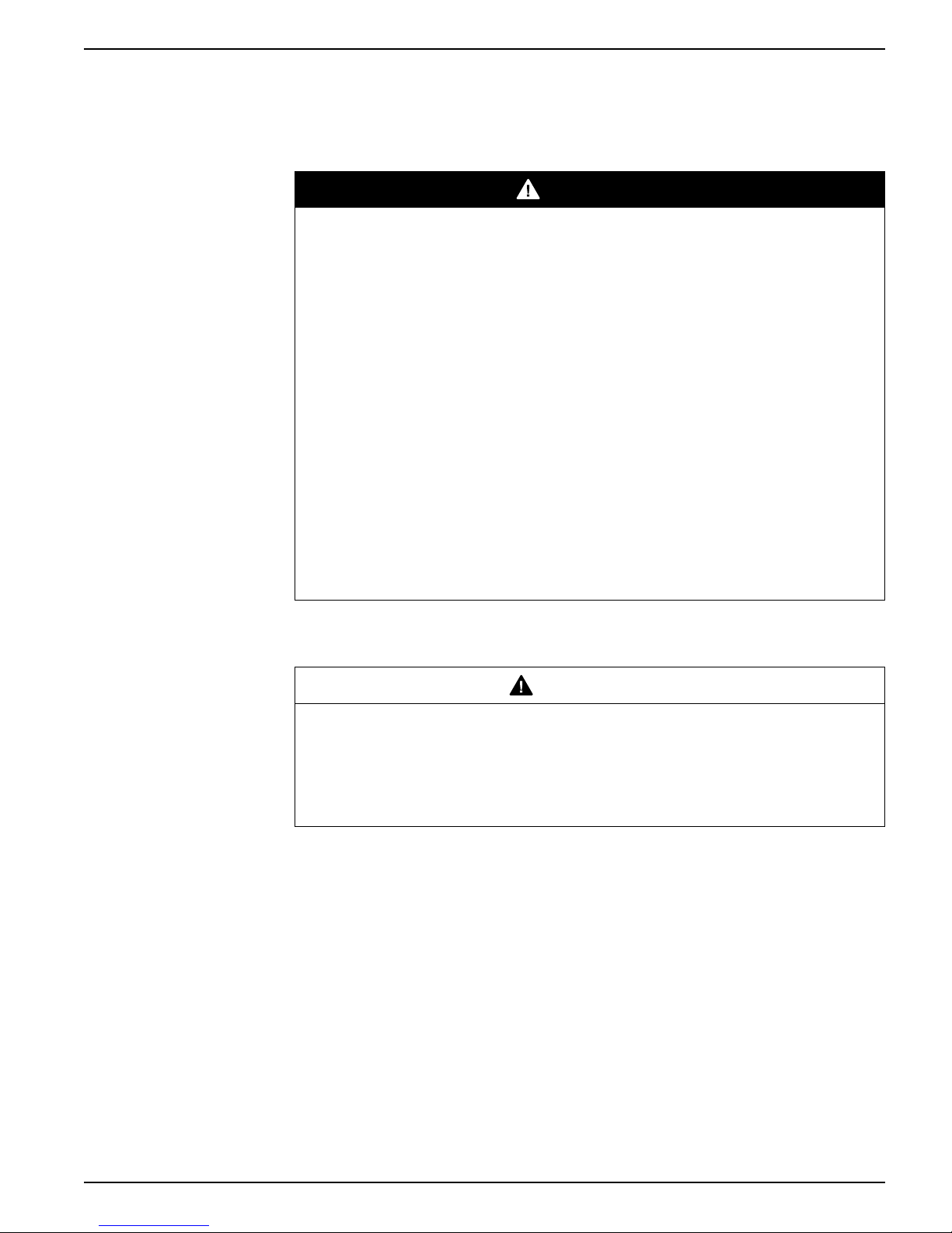
Safety precautions
Installation, wiring, testing and service must be performed in accordance with all local
and national electrical codes.
DANGER
HAZARD OF ELECTRIC SHOCK, EXPLOSION, OR ARC FLASH
Failure to follow these instructions will result in death or serious injury.
• Apply appropriate personal protective equipment (PPE) and follow safe electrical
work practices. See NFPA 70E in the USA, CSA Z462 or applicable local
standards.
• Turn off all power supplying this device and the equipment in which it is installed
before working on the device or equipment.
• Always use a properly rated voltage sensing device to confirm that all power is
off.
• Treat communications and I/O wiring connected to multiple devices as hazardous
live until determined otherwise.
• Do not exceed the device’s ratings for maximum limits.
• Never short the secondary of a potential/voltage transformer (PT/VT).
• Never open circuit a current transformer (CT).
• Always use grounded external CTs for current inputs.
• Do not use the data from the meter to confirm power is off.
• Replace all devices, doors and covers before turning on power to this equipment.
NOTE: See IEC 60950-1:2005, Annex W for more information on communications and
I/O wiring connected to multiple devices.
WARNING
UNINTENDED OPERATION
Failure to follow these instructions can result in death, serious injury, or
equipment damage.
Do not use this device for critical control or protection applications where human or
equipment safety relies on the operation of the control circuit.
7EN05-0336-01 9

9410 series Meter overview
Meter overview
9410 overview
The 9410 series power and energy meters help meet the needs of your energy
monitoring and cost management applications.
All 9410 meters comply with international metering accuracy standards. You can
customize your meter by loading specialized frameworks, and adding option modules
and incorporating mounting accessories into the physical installation.
Meter features
True RMS metering to the 63rd harmonic
Active (kW), reactive (kVAR) and apparent (kVA) power
600 V direct connection on voltage inputs
Minimum/maximum readings of metered data
Power quality readings (THD)
Downloadable firmware and template
Configuration through integrated or remote display
Modbus master, Ethernet gateway protocols supported
Web interface
Sag/Swell capture for voltage and currents
Time synchronization to 1 ms accuracy
Dual port Ethernet (two physical ports, one Ethernet IP address)
Water Air Gas Electricity Steam (WAGES) support
Time of use support
Trending and forecasting
Alarms (active and historic) display viewing and acknowledgment
Multiple languages supported
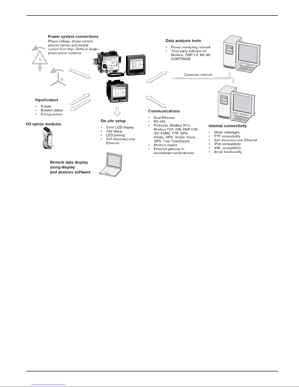
Your meter in an energy management system
In an energy management system the 9410 meter collects and aggregates data.
This data is used to perform non-critical control or is shared with other equipment in
the energy management system. Data from the meter can be used by energy
management software to help with energy cost management, trending and forecasting,
network management, power quality analysis, and more.
The meter is user-configurable to adapt to many situations. Communications allow
data to be shared simultaneously across multiple networks, built-in and optional I/O
provides monitoring and non-critical control capabilities, and a variety of display and
analysis tools can be used to monitor your system.
The following graphic outlines your meter’s capabilities in an energy management
system.
10 7EN05-0336-01
Meter overview 9410 series
Measured parameters
Energy
Your meter provides bi-directional 4-quadrant energy metering.
Your meter provides active, reactive and apparent energy values.
• kWh, kVARh, kVAh delivered and received
• kWh, kVARh, kVAh net (delivered - received)
• kWh, kVARh, kVAh total (delivered + received)
• Volt-squared-hours and amp-squared-hours
Energy parameters can be logged automatically on a programmed schedule.
All energy values represent the total for all three phases.
Demand
Your meter supports several demand calculation methods, including block, rolling
block, synchronized and predicted demand.
It can measure demand on any instantaneous value and record peak (maximum) and
minimum demand with time and date information.
• kW, kVAR, kVA demand
• kW, kVAR, kVA peak demand
• Amps, Volts demand
7EN05-0336-01 11

9410 series Meter overview
Instantaneous
Your meter provides one second and half-cycle measurements, per phase and totals
for many values.
• Voltage and current
• Apparent power (kVA), active power (kW) and reactive power (kVAR)
• Power factor and frequency
• Voltage and current unbalance
Harmonics
Your meter provides harmonic distortion metering, recording and real-time values for
all voltage and current inputs.
• Individual harmonics (including magnitude and phase angle) up to the 63
harmonic
• Total even harmonic distortion (TEHD) and total odd harmonic distortion (TOHD)
• Total harmonic distortion (THD) or total demand distortion (TDD)
• K-factor, Crest factor
rd
Min/max recording
Power quality
Your meter records new minimum and maximum data every recording interval for a
variety of values.
• Voltage and current
• kW, kVAR and kVA
• Power factor
• Frequency
• Voltage unbalance
• Plus any measured value
Your meter measures and records voltage and current sags and swells.
Your meter also has many power quality related features.
• Disturbance direction detection: this allows the meter to analyze disturbance (sag/
swell) information to help determine the direction of the disturbance relative to the
meter.
• Setpoint learning: this allows the meter to learn the power quality characteristics of
your system, to help identify what constitutes a sag or a swell.
• COMTRADE: this allows the meter to save waveform data in COMmon format for
TRAnsient Data Exchange (COMTRADE) on its internal FTP server.
Your meter includes the following power quality compliance:
• EN50160: Your meter measures and presents statistics for determining EN50160
compliance.
• IEC 61000-4-30: Your meter complies with the IEC 61000-4-30 power quality
standard.
• IEC 62586: Your meter complies with the IEC 62586 power quality standard.
12 7EN05-0336-01

Meter overview 9410 series
Localization
The meter can be customized to use different regional settings.
Localization settings determine:
• The language used for the display and webpages
• Time, date and digit formats
• Displayed phase labels (123/ABC)
• IEEE (Institute of Electrical and Electronics Engineers) or IEC (International
Electrotechnical Commission) conventions for power, power factor and energy
You can configure your meter’s localization settings through the display or using ION
Setup.
Data display and analysis tools
Display
Use the meter’s display for local monitoring and standalone applications.
The color LCD display lets you view real-time values, events and alarms, and perform
basic device configuration. Connect a remote display to a meter without an integrated
display to view meter data and perform basic meter configuration.
Active and historical alarms
The meter’s display shows an alarm icon and the alarm LED flashes if your meter
detects an active alarm condition.
Depending on the priority of the alarm, your meter’s display also flashes. You can view
and acknowledge active alarms and historic alarms and events through the display
and software webpages. An active alarm becomes a historic alarm when the alarm
condition no longer exists.
Meter internal web server feature
Your meter’s internal web server provides quick and easy access to real-time energy
and basic power quality information without special software using an on-board web
server combined with an Ethernet port.
The built-in web pages display selected energy and power quality information through
the web-enabled device; these pages also support basic meter configuration.
Email messaging feature
You can configure your meter to automatically email information, whether notification
of a high-priority event or a regularly scheduled send of logged data, to an external
email address.
Specify the type of event that triggers an email alert, such as a power quality
disturbances or interval for logged data. Email messages from your meter are received
like any other email message.
Supported protocols
Your meter’s fundamental protocol and architecture is ION.
7EN05-0336-01 13
9410 series Meter overview
You can integrate the meter into various industry-standard networks. Data that the
meter measures can be made available to other devices using Modbus, DNP 3.0 and
SNMP as well as the MV-90 translation system. You can configure the meter to import
data from other devices on these networks. Your meter supports the IEC 61850
protocol and COMTRADE waveform data format.
Your meter also supports IPv6, DPWS and RSTP Ethernet protocols.
ION Setup device configuration tool
ION Setup is a free configuration tool for your meter that allows you to remotely
configure your meter’s features over Ethernet or serial communications.
• Use the setup screens to guide you through the process of configuring your meter.
• Use the real-time data screens to verify your meter’s configuration.
• Use the data screens to view your meter’s recorded data.
• Use the charting function to view your meter’s recorded waveforms.
You can download ION Setup from www.usa.siemens.com/pds.
See the online ION Setup help, available from www.usa.siemens.com/pds, for
instructions on connecting to your meter.
Meter types
Mounting adaptors
The 9410 series is available in two physical form factors, and has several accessories.
Model Commercial reference Description
9410DC US2:9410DC Panel-mounted meter with integrated display
9410TC US2:9410TC DIN rail-mounted meter without display, which can
be connected to a remote display
9410RC US2:9410RC DIN rail-mounted meter packaged with a remote
display
948DISP96 US2:948DISP96 Remote display (for DIN meter only)
948M2DO6DI US2:948M2DO6DI Digital I/O option module (2 out, 6 in)
948M2AO4AI US2:948M2AO4AI Analog I/O option module (2 out, 4 in)
9410SK US2:9410SK Voltage and current sealing kit
94PMAK 94PMAK Mounting adapter kit for remote display and DIN
meter
There are different mounting adaptor accessories that can help when installing your
meter in existing panels and cutouts where the default mounting hardware is not
appropriate.
Mounting adaptor kits are ordered separately from the meter.
Terminal covers
The voltage and current terminal covers help prevent tampering with the meter’s
voltage and current measurement inputs.
14 7EN05-0336-01

Meter overview 9410 series
The terminal covers enclose the terminals, the conductor fixing screws and a length of
the external conductors and their insulation. The terminal covers are secured by
tamper-resistant meter seals.
These covers are included for meter models where sealable voltage and current
covers are required to comply with revenue or regulatory standards.
The meter terminal covers must be installed by a qualified installer.
Refer to your meter's installation sheet or the instructions that came with your terminal
covers for instructions on installing the terminal covers.
Replacement hardware
You can order replacement mounting and installation hardware for your meter and
accessories.
7EN05-0336-01 15
9410 series Basic setup
Basic setup
Default values for commissioning
Use these default settings for the first time you connect to and configure your meter.
Parameter Default value
Display password (also for logging onto meter webpages) 0
Username (for logging onto meter webpages) 9410
IP address 169.254.0.10
Subnet mask 255.255.0.0
Gateway 0.0.0.0
Unit ID 1
Language English
Meter setup
Volts mode
PT/CT setup
You can configure your meter’s basic metering parameters using the display.
Parameter Values Description
Volts Mode 4W-Wye, Delta, 3W-Wye,
Single, Demo
PhaseOrder ABC, ACB The power system’s phase order
Parameter Values Description
PT Primary 1 to 999,999.99 The potential transformer’s primary winding voltage
PT Secondary 1 to 999,999.99 The potential transformer’s secondary winding
CT Primary 1 to 999,999.99 The current transformer’s primary winding current
The power system’s configuration
rating
NOTE: PTs are also referred to as a VTs or voltage
transformers.
voltage rating
NOTE: PTs are also referred to as a VTs or voltage
transformers.
rating
CT Secondary 1 to 999,999.99 The current transformer’s secondary winding
I4 Primary 1 to 999,999.99 The I4 current transformer’s primary winding
I4 Secondary 1 to 999,999.99 The I4 current transformer’s secondary winding
16 7EN05-0336-01
current rating
current rating
current rating
Basic setup 9410 series
Voltage polarity setup
Parameter Values Description
Va Polarity Normal, Inverted The polarity of the potential transformer on Va
Vb Polarity Normal, Inverted The polarity of the potential transformer on Vb
Vc Polarity Normal, Inverted The polarity of the potential transformer on Vc
Current polarity setup
Parameter Values Description
Ia Polarity Normal, Inverted The polarity of the current transformer on Ia
Ib Polarity Normal, Inverted The polarity of the current transformer on Ib
Ic Polarity Normal, Inverted The polarity of the current transformer on Ic
I4 Polarity Normal, Inverted The polarity of the current transformer on I4
Nominal values
Parameter Values Description
V Nominal 1 to 999,999 The nominal (normal) voltage of the power system
I Nominal 1 to 999,999 The nominal (normal) current of the power system
Nominal
Frequency
50, 60 The nominal (normal) frequency of the power
system
Minimum configuration requirements for basic metering
At a minimum, you must configure some parameters to help your meter perform basic
metering functions.
Setup screen Screen Minimum configuration
Meter Setup Volts Mode Volts mode
PT/CT Setup PT, CT and I4 CT primary and secondary
Nominal values V nominal, I nominal, Nominal frequency
NOTE: You must also configure all the parameters related to the meter features you
are using, for example, you must configure the DNS server address if you are using
the meter’s DNS feature.
Lost user access
If you lose your meter’s user access (password) information, contact your local
Siemens Industry representative for instructions on how to return your meter for factory
reconfiguration.
NOTE: Have your meter’s serial number available for reference.
7EN05-0336-01 17
9410 series Hardware reference
Hardware reference
Supplemental information
This document is intended to be used in conjunction with the installation sheet that
ships in the box with your meter and accessories.
See your device’s installation sheet for information related to installation.
See your product’s technical datasheet at www.usa.siemens.com/pds for the most upto-date and complete specifications.
See your product’s catalog pages at www.usa.siemens.com/pds for information about
your device, its options and accessories.
You can download updated documentation from www.usa.siemens.com/pds or contact
your local Siemens Industry representative for the latest information about your
product.
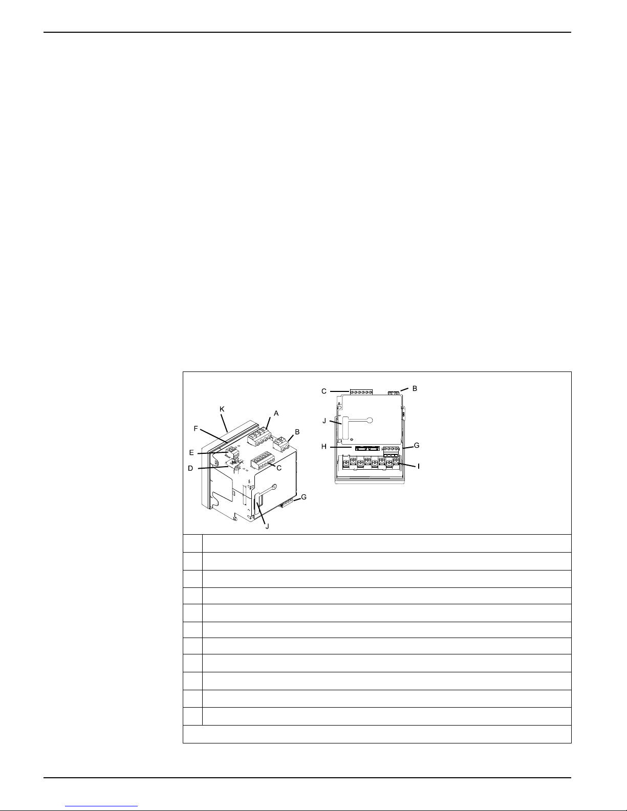
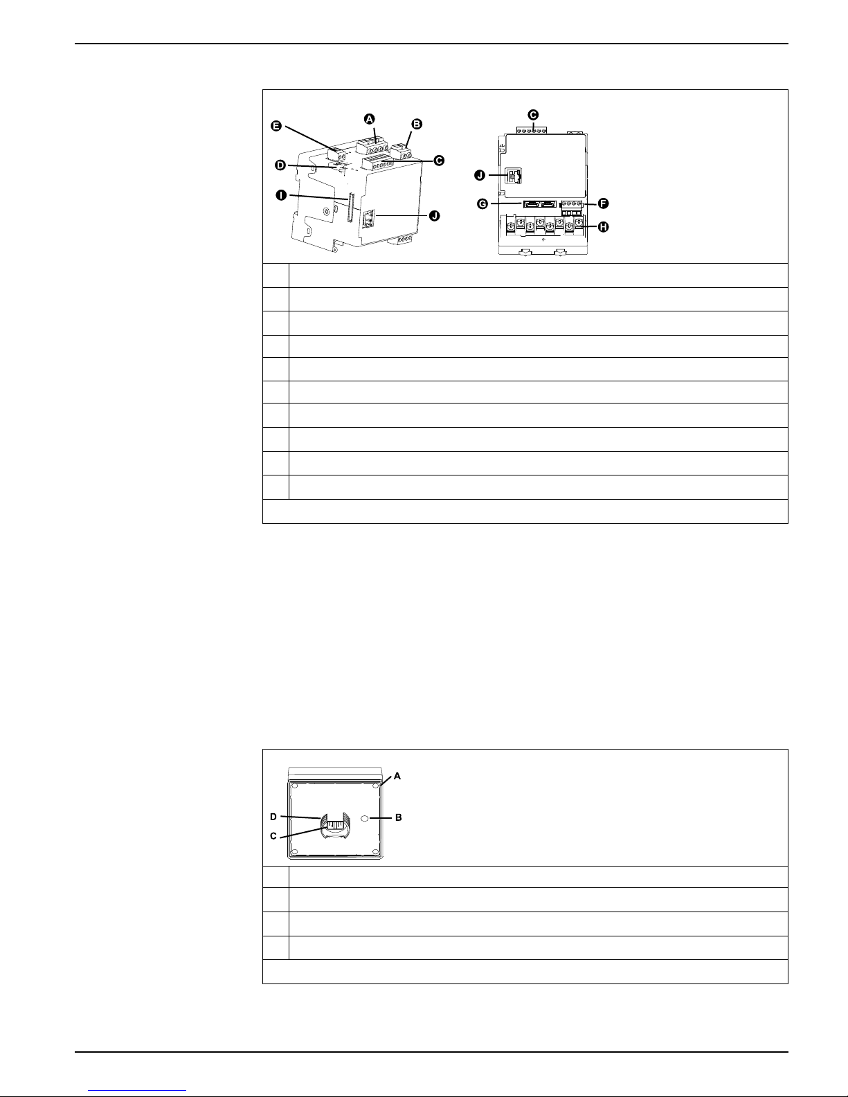
Meter base
Panel meter
Your meter base has two form factors, panel mount and DIN mount.
A Voltage inputs
B Control power
C Digital inputs (3)
D Revenue lock switch cover
E Digital output
F Gasket
G RS-485
H Ethernet (2)
I Current inputs
J Option module connector
K Display
Mounting hardware and accessories not shown.
18 7EN05-0336-01
Hardware reference 9410 series
A
D
C
B
DIN meter
A Voltage inputs
B Control power
C Digital inputs (3)
D Revenue lock switch cover
E Digital output
F RS-485
G Ethernet (2)
H Current inputs
I Option module connector
J Remote display connector
Mounting hardware and accessories not shown.
See the 9410 catalog pages, available from www.usa.siemens.com/pds, or consult
your local Siemens Industry representative for information about your device, its
options and accessories.
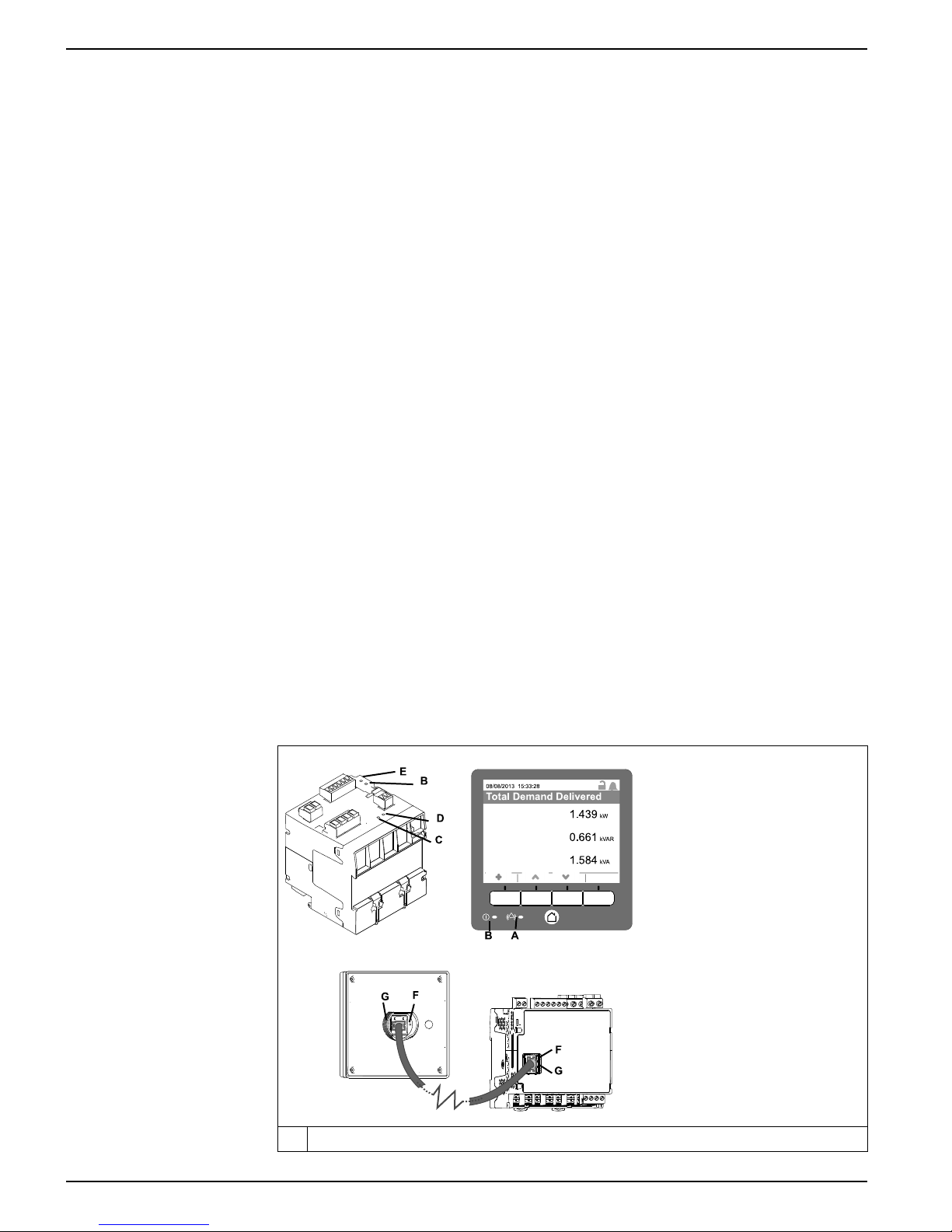
Remote meter display (RMD)
The remote meter display can be used with DIN meters.
It has the same buttons and icons as the display on a panel meter, and is powered by
the connection to the meter. A remote display cannot be used with meters that have an
integrated display
A Gasket
B Alignment pin location
C Display connection
D Mounting post
Mounting hardware and accessories not shown.
7EN05-0336-01 19
9410 series Hardware reference
1.439
kW
0.661
kVAR
8/08/2 013 15:3 3:28
Tota l Dema n d De livered
1.584
kVA
A
E
B
B
D
C
F
G
F
G
Mounting adaptors
There are different mounting adaptor accessories that can help when installing your
meter in existing panels and cutouts where the default mounting hardware is not
appropriate.
Mounting adaptor kits are ordered separately from the meter.
Terminal covers
The voltage and current terminal covers help prevent tampering with the meter’s
voltage and current measurement inputs.
The terminal covers enclose the terminals, the conductor fixing screws and a length of
the external conductors and their insulation. The terminal covers are secured by
tamper-resistant meter seals.
These covers are included for meter models where sealable voltage and current
covers are required to comply with revenue or regulatory standards.
The meter terminal covers must be installed by a qualified installer.
Refer to your meter's installation sheet or the instructions that came with your terminal
covers for instructions on installing the terminal covers.
Replacement hardware
You can order replacement mounting and installation hardware for your meter and
accessories.
LED locations
The LED indicators alert or inform you of meter activity.
A Alarm
20 7EN05-0336-01
Hardware reference 9410 series
B Status
C Energy pulsing
D Infrared energy pulsing
E Revenue lock status
F Remote display connection link
G Remote display connection activity
Energy pulsing LED behavior
The visible and infrared LEDs are configured by default to pulse based on energy
measured by the meter.
You can configure the pulse weight (pulses per kWh) and the energy source.
Energy pulsing is used to help verify the energy measurement accuracy of your meter
for revenue purposes.
Related Topics
• Energy pulsing
Revenue lock LED behavior
The revenue lock LED indicates the lock status of the meter.
State Description
Off The meter is not revenue locked.
On The meter is revenue locked.
Flashing New revenue lock state is pending; power cycle your meter to set the revenue lock
to on or off.
Remote display connection LED behavior
There are two LEDs in the remote display connector that indicate the state of
communications between the meter and remote display.
LED Description
Green (link) On: link established.
Off: no link established with the remote display. Check the connections to the
remote display and DIN meter.
Yellow (activity) Flashing: active communications between the meter and the remote display.
Panel-mount meter and remote display mounting and wiring
recommendations
There are supplemental mounting and wiring recommendations that apply to panelmount meters and remote displays.
• The meter is intended to be mounted inside a ¼-DIN panel cutout.
7EN05-0336-01 21
Off: no communication activity. Check remote display and meter operation.
9410 series Hardware reference
• Inspect the gasket (installed around the perimeter of the display) and make sure it
is secured properly and not damaged.
• The meter retainer clips, located on either side of the meter base and used to
secure the meter in the panel, do not usually require any tools to install. If
necessary, for panels with limited space, you can use a long-handled slot
screwdriver to help install the meter retainer clips.
• The remote display can only be used with the DIN meter; it cannot be used by
meters with an integrated display.
• The remote display’s power and communications is provided through a single,
direct, point-to-point connection from the remote display to the DIN meter.
Power system wiring
You can connect the meter’s voltage inputs directly to the phase voltage lines of the
power system if the power system’s line-to-line or line-to-neutral voltages do not
exceed the meter’s direct connect maximum voltage limits.
The maximum voltage allowed for direct connection may be lower than the
manufacturer-specified limits, depending on the local electrical codes and regulations.
If your system voltage is greater than the specified direct connect maximum voltage,
you must use voltage (potential) transformers (VTs/PTs) to step down the voltages.
RS-485 wiring
RS-485 cable
RS-485 terminals
Connect the devices on the RS-485 bus in a point-to-point configuration, with the (+)
and (-) terminals from one device connected to the corresponding (+) and (-) terminals
on the next device.
Use a shielded 2 twisted pair or 1.5 twisted pair RS-485 cable to wire the devices. Use
one twisted pair to connect the (+) and (-) terminals, and use the other insulated wire to
connect the C terminals
The total distance for devices connected on an RS-485 bus should not exceed 1200 m
(4000 ft).
C Common. This provides the voltage reference (zero volts) for the data plus and data minus
signals
Shield. Connect the bare wire to this terminal to help suppress signal noise that may be present.
Ground the shield wiring at one end only (either at the master or the last slave device, but not
both.
-
Data minus. This transmits/receives the inverting data signals.
+
Data plus. This transmits/receives the non-inverting data signals.
NOTE: If some devices in your RS-485 network do not have the C terminal, use the
bare wire in the RS-485 cable to connect the C terminal from the meter to the shield
terminal on the devices that do not have the C terminal.
22 7EN05-0336-01
Hardware reference 9410 series
Ethernet communications connections
Your meter’s dual port Ethernet connections enable you to use straight-line or network
loop (ring) topologies.
If local network loop Ethernet topologies are required, you must enable RSTP for your
meter’s Ethernet communications to function.
Only use unshielded CAT5/5e UTP Ethernet cables to wire your meter’s Ethernet
communications. Other cable types may provide an undesired ground path.
NOTICE
EQUIPMENT DAMAGE
Failure to follow these instructions can result in equipment damage.
Only use unshielded CAT5/5e UTP Ethernet cables.
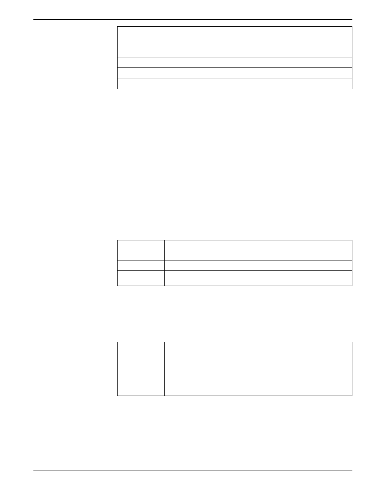
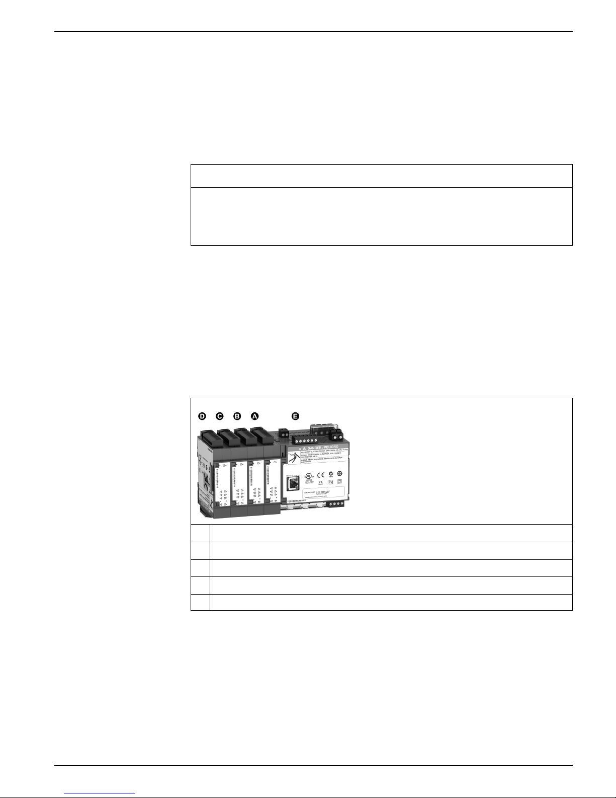
Option modules overview
Option modules are ordered separately from your meter, and can be connected to your
meter without specialized equipment.
Option modules are identified based on the physical order of the attached modules.
The option module attached directly to the meter is module A, the module attached to
module A is module B, and so on. The option module identifier is added to the ION
module name and ION label to uniquely describe each possible combination of option
modules.
A Option module A
B Option module B
C Option module C
D Option module D
E Meter
For example, a meter with two option modules, consisting of an analog option module
directly attached to the meter (A) and a digital option module attached second (B),
describes the Q2 analog output of module A as Port A Q2 and the S3 digital input of
module B as Port B S3.
Maximum number of option modules
The maximum number of option modules supported by the device is four. However,
there are limitations.
7EN05-0336-01 23
9410 series Hardware reference
Depending on the type and quantity of option modules attached to your meter, you
may need to reduce your meter’s maximum operating temperature or limit the number
of option modules. Refer to Maximum operating temperature, page 166 for more
information.
For a panel mount meter, one limitation on the number of modules that can be
attached is the physical strength of the meter mounting hardware. If your meter is
mounted in an area subject to vibration or other physical stresses, your meter’s ability
to physically support multiple option modules and maintain a seal against the mounting
surface may be affected. Refer to Mechanical characteristics, page 164 for more
information.
NOTICE
EQUIPMENT DAMAGE
Failure to follow these instructions can result in equipment damage.
Do not exceed the maximum number of option modules.
Related Topics
• Specifications
24 7EN05-0336-01
Meter display 9410 series
A
D
E
F
GHI
B C
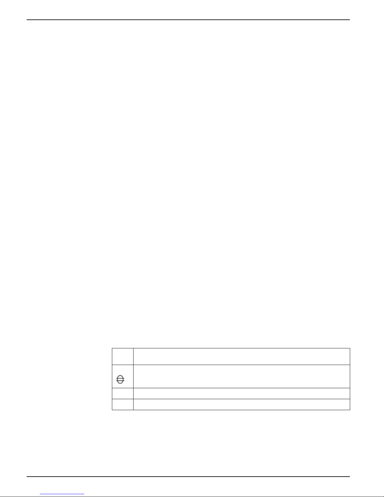
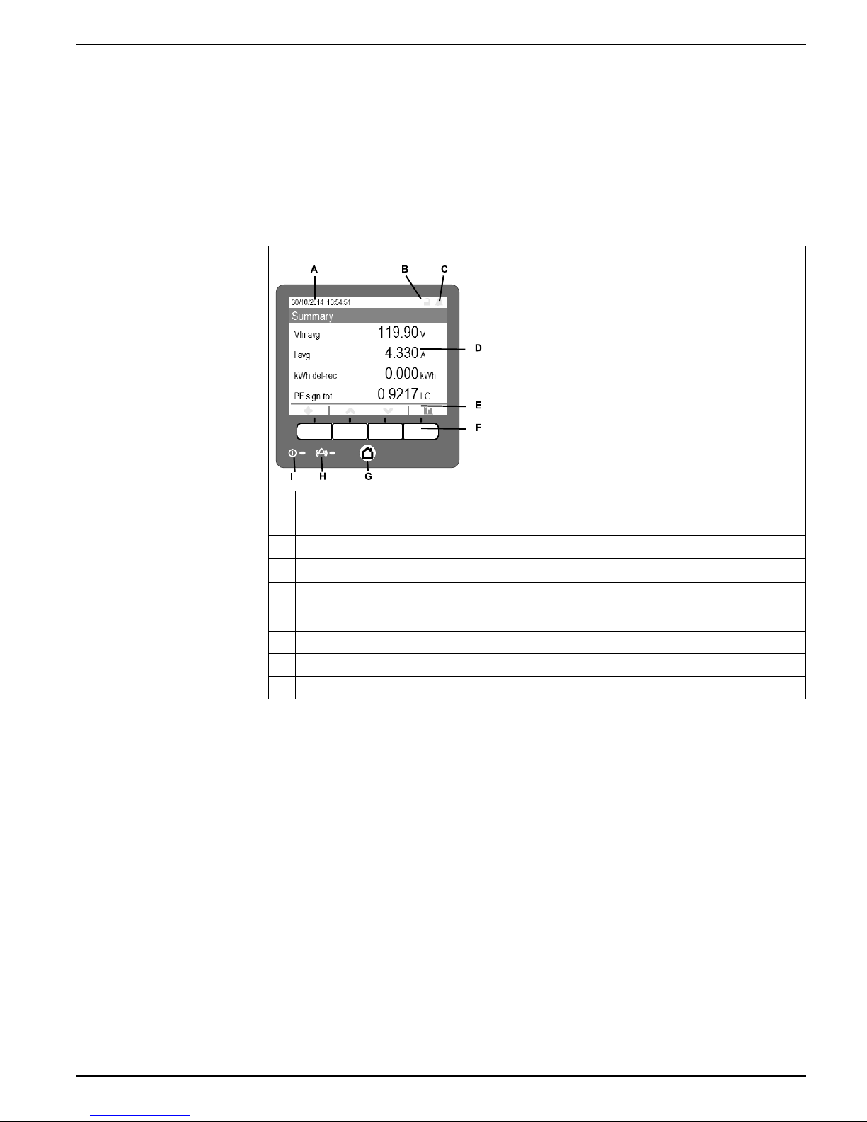
Meter display
Display overview
The display allows you to view meter data and perform basic configuration.
Your meter can have either an integrated or an optional remote display. The integrated
and remote display screens have the same meter data and setup screens. Only
meters without an integrated display can use the remote display.
Home button
A Date/time
B Revenue lock icon
C Alarm icon
D Display
E Navigation icons
F Navigation buttons
G Home button
H Alarm LED
I Status LED
NOTE: Your meter’s display backlight dims after a defined period of inactivity. When
the meter detects an unacknowledged active high priority alarm, the display flashes
until the alarm is acknowledged.
Pressing the home button takes you to the associated menu screen. If you are in a
data screen, pressing the home button takes you to the display menu, and pressing
home twice takes you to the summary display screen. If you are in a setup screen,
pressing home takes you to the setup menu, and pressing home again takes you to
the display menu.
Revenue lock icon
7EN05-0336-01 25
The revenue lock icon indicates the lock status of the meter.
When gray and open, the meter is unlocked. When green and closed, the meter is
locked. You can lock and unlock your meter using the revenue lock switch located on
the body of your meter.
9410 series Meter display
Related Topics
• Revenue locking
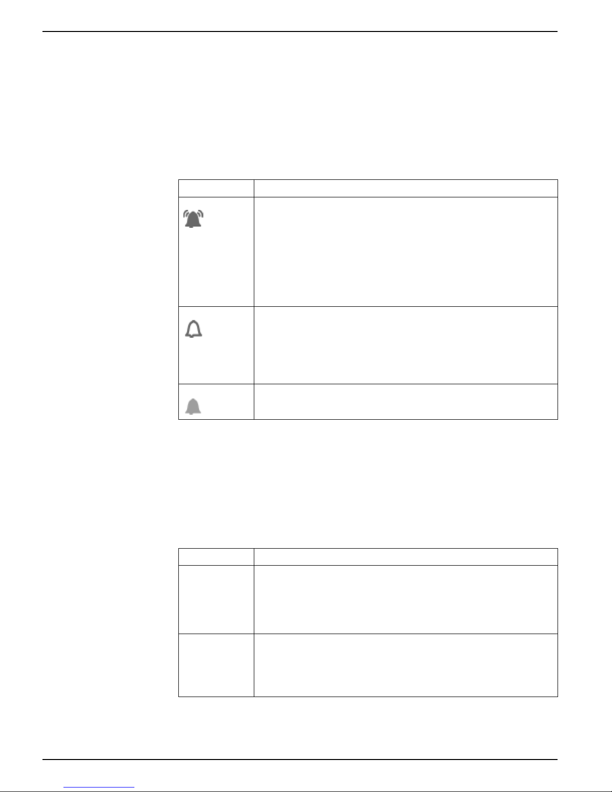
Alarm icon
The alarm icon indicates the highest level and state of alarms detected by your meter.
For example, if the meter detects a low priority and a high priority active alarm, the
alarm icon indicates a high priority active alarm.
NOTE: Alarms can only be viewed and acknowledged through your meter’s display.
Icon Description
Active alarm indicator:
• Red: high priority alarm state detected
• Yellow: medium priority alarm state detected
• Blue: low priority alarm state detected
The alarm indicator flashes until you acknowledge the alarm.
The alarm indicator changes to the historic alarm indicator of the appropriate level
when the alarm state is no longer detected by the meter.
NOTE: Your meter’s display backlight flashes for unacknowledged high priority
active alarms.
Unacknowledged historic alarm indicator:
• Red: unacknowledged high priority historic alarm
• Yellow: unacknowledged medium priority historic alarm
NOTE: Low priority historical alarms are not indicated.
The active alarm indicator changes to the historic alarm indicator of the appropriate
level when the alarm state is no longer detected by the meter.
Related Topics
• Alarms overview
Alarm and status LED indicators
Your meter has alarm and status LEDs on the display.
These LEDs cannot be configured for other uses.
LED Description
Status Off: unpowered
Alarm Off: no active or unacknowledged historic alarms
No active or unacknowledged high or medium priority historic alarms
Steady green: normal operation
Flashing red: no communications (remote display only)
Steady red: firmware upgrade required (remote display only)
Flashing red/green: startup or firmware upgrade sequence in progress
On: acknowledged active alarm
Flashing: active alarm
NOTE: Your meter’s display backlight flashes for unacknowledged high priority
active alarms.
26 7EN05-0336-01
Meter display 9410 series
Related Topics
• LED locations
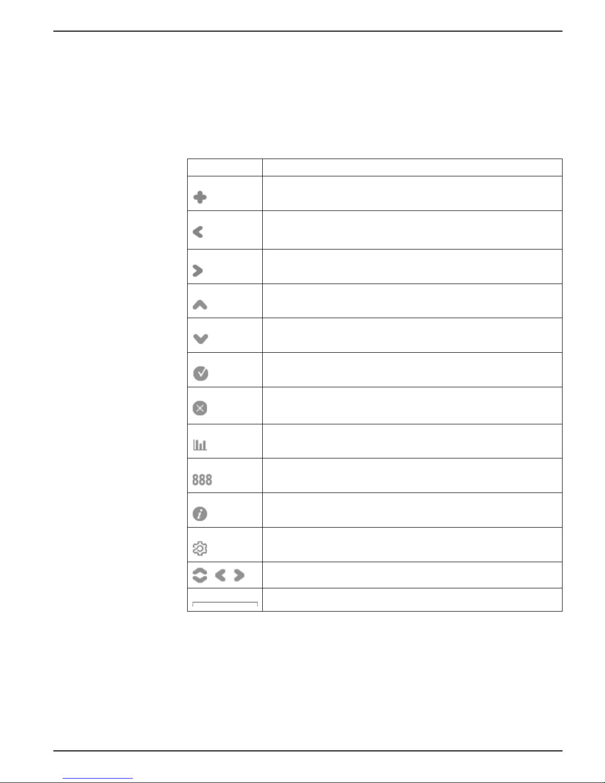
Navigation symbols
Navigation symbols are displayed on the bottom of the screen above their
corresponding navigation button.
NOTE: If the symbol is gray, that navigation function is not available.
Symbol Description
More
Pressing this button displays additional screens.
Left
Pressing this button moves the displayed cursor one position to the left. If you are in
a more or info screen, it returns you to the previous screen.
Right
Pressing this button moves the displayed cursor one position to the right.
Up
Pressing this button takes you to the previous screen or menu item.
Down
Pressing this button takes you to the next screen or menu item.
Select
Pressing this button selects or confirms the highlighted value.
Cancel
Pressing this button cancels the current selection and returns you to the previous
screen.
Graphic
Pressing this button takes you to a graphical data display.
Numeric
Pressing this button takes you to a numeric data display.
Info
Pressing this button takes you to a detailed information screen.
Edit
Pressing this button allows you to edit the displayed parameter.
Pressing these buttons allow you to navigate parameter tables in the setup screens.
Pressing both buttons allows you to perform the described action.
More screens access
You can access additional screens.
Pressing the navigation button associated with the more icon brings up a list of
additional screens related to the displayed screen. Press cancel to remove the list. If
you do not press any button, the list automatically disappears after a short period of
time.
7EN05-0336-01 27
9410 series Meter display
Summary
Sample
Sum ma ry
Active Alarms
Inputs/Outputs
Setup Menu
Nameplate
Custom Screens
Alarms
Historical Alarm s
Events
Events
Power Factor
Energy
Energy Delivered
Energy Delivered-Recei ved
Energy Received
TOU En ergy Delivered A&B
T
O
U
E
n
e
r
g
y
D
e
l
i
v
e
r
e
d
C
&
D
I Max (I4)
Frequency
Current
I Averag e
I Min (Ia Ib Ic)
I Min (I4)
I Max (Ia Ib Ic)
Freque nc y
Volts ll Average Volts ll Min
Basic Readings
Voltage
Volts L-L
Volts L-N
Volts Unbalanced
Volts ln Average Volts ln Min
Volts ll Max
Volts ln Max
Power T otal Min Power T o tal Max
Power
Power Sum ma ry
Power Total
Power Phas e A
Power Phas e B
Power Phas e C
Peak De ma nd Delivere d Total
TOU P eak De ma nd Delivered (A-B)
Demand
Total Demand Delivered
Total Demand Re ceived
Peak De ma nd Received Total
TOU P
ea k De ma nd Re ce ived (A-B)
Power F actor To tal Min Power F actor Tota l Max
TOU P eak De ma nd Delivered (C-D)
TOU P
ea k De ma nd Re ce ived (C-D)
Power F reque ncy Compliance
Power Quality
EN50160
Harmonics
Phasors
Digital Inputs
Digital Outputs
Analog Inputs
Analog Outputs
EN50160 Power Fre que ncy
EN50160 Nominal Supp ly Voltage
EN50160 Supply Voltage - V1
Voltage Compliance - V1
Voltate Compliance - V2
Voltage Compliance - V3
Volts Unbalance C omp liance
Volts Ha rmonics Complianc e - V1
Volts Ha rmonics Complianc e - V2
Volts Ha rmonics Complianc e - V3
EN50160 Supply Voltage - V2
EN50160 Supply Voltage - V3
EN50160 Volts Unba lanc e
EN50160 Volts Ha rmo nics - V1
EN50160 Volts Ha rmo nics - V2
EN50160 Volts Ha rmo nics - V3
V1 Harm onics V2 Harm onics V3 Harm onics
Voltage THD
Curre nt THD
I1 Harm onics I2 Harm on ics I3 Harm onics I4 Harmonics
Phasor Diagra m
Nameplate
Up to 2 0 cus tom sc ree ns
See Set u p menu s ection for details
Overrange indication
If any value measured by the meter is too large to fit on the meter’s display, the meter
initially reduces the size of the text to try and make the value fit.
If the value is still too large to be displayed, the meter truncates the value starting with
the least significant digit, and encloses the truncated value in a red box.
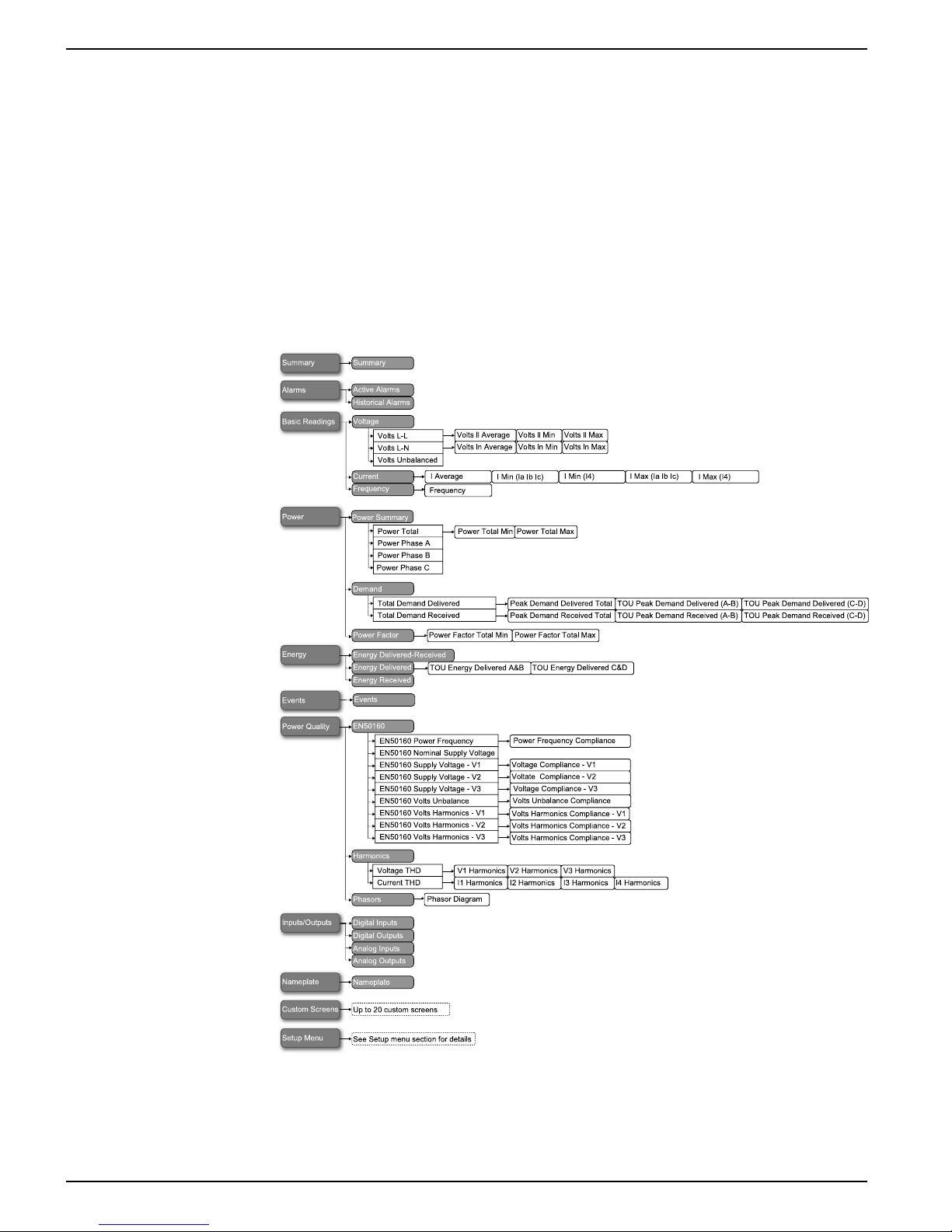
Display menu
The display menu allows you to select data for viewing and to access the setup menu.
NOTE: Your meter’s menus may appear slightly different than shown depending on
your display settings.
Data display screens
Your meter’s default display screens show measured and calculated information about
the power system being monitored.
28 7EN05-0336-01
Meter display 9410 series
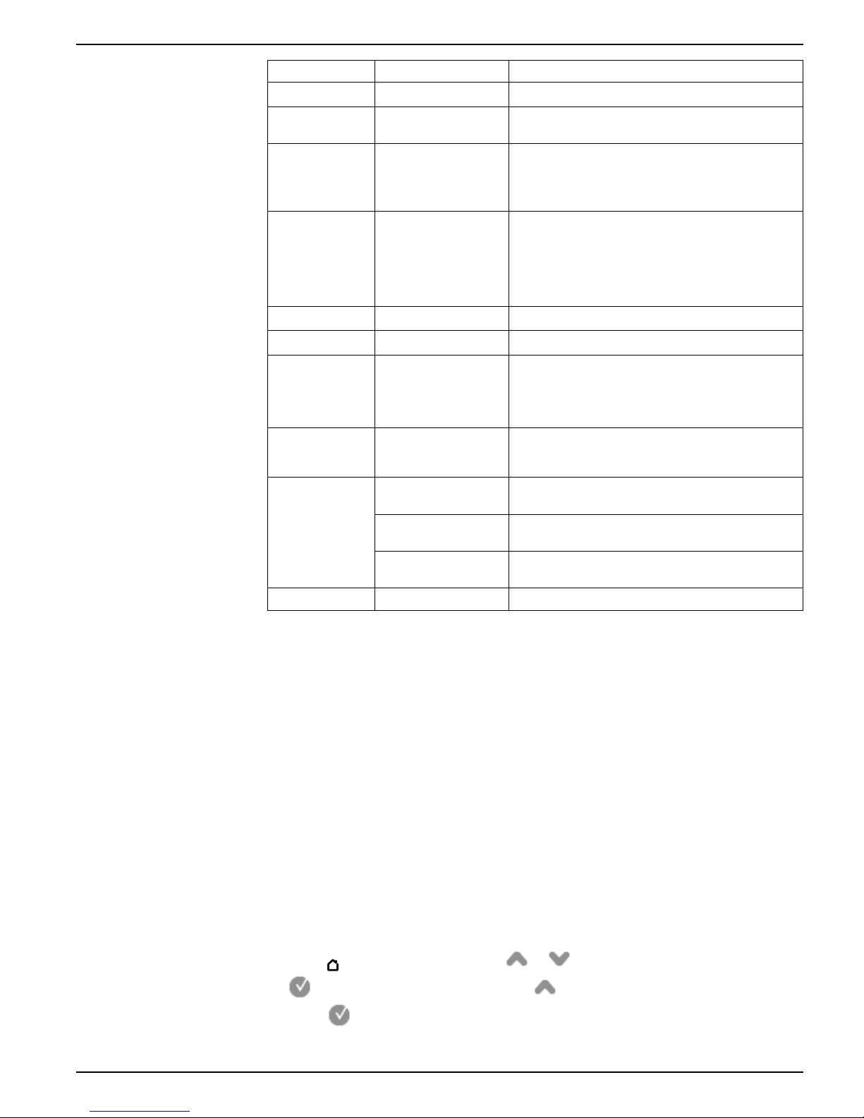
Menu Menu screens Content
Summary Summary Power system summary
Alarms Active alarms, historical
Basic readings Voltage, current,
Power Power summary,
Energy Energy Energy delivered-received, delivered and received.
Events Events Meter event log entries listing and details.
Power quality EN50160, harmonics,
Inputs/outputs Digital inputs, digital
Nameplate
alarms
frequency
demand, power factor
phasors
outputs, analog inputs,
analog outputs
Nameplate
Nameplate (MID meter
only)
Active and historical alarms can be viewed and
acknowledged.
• Power system voltage (line-to-line or line-to-neutral),
current and frequency values.
• Average, minimum and maximum values are also
provided.
• Per-phase and total kW, kVAR and kVA values,
along with minimum and maximum values.
• Delivered and received demand values including
peak demand.
• Per-phase and total power factor along with
minimum and maximum values.
• EN50160 values.
• Voltage and current harmonics, with individual and
total harmonic values.
• Phasor diagram with magnitude and angle values.
Digital and analog I/O values and counts.
Meter model, firmware version and serial number, along
with owner and tag information.
Feature set, firmware version, firmware CRC, Pulse
constant and template information
Nameplate (MID meter
only)
Custom screens
—
Data viewing using your meter’s display
Use the navigation buttons to view data on your meter’s display.
The following examples show how to use the navigation buttons to view data in
numeric or graphical format, select and view additional menu screens, and view
detailed information about alarms and acknowledge them.
NOTE: Your display may appear differently than shown, depending on your meter’s
power system and display settings.
NOTE: Your navigation icons change color depending on the type of screen being
viewed. If an icon is gray, that navigation option is not available and nothing will
happen when you press the button associated with that icon.
Example: viewing the alarm screens
Use the display navigation buttons to access the alarm screens, display detailed
information, and acknowledge active and historic alarms.
1. Press
to display the menu. Press or until Alarms is highlighted. Press
Volts mode, nominal voltage, nominal current, nominal
frequency, PT ratio and CT ratio
Custom screens
Press
total number of active alarms.
7EN05-0336-01 29
to display the alarm screens. Press until Active Alarms is highlighted.
to display active alarms. The Active Alarms title lists, in brackets, the

9410 series Meter display
2. Press or to highlight a specific alarm, in this case an unbalanced currents
alarm. Press
press
to return to the Active Alarms screen. Press both and
to display detailed information about the highlighted alarm, and
simultaneously to acknowledge all active alarms.
3. Press to display the menu. Press to highlight Historical Alarms. Press
to display historical alarms. The Historical Alarms title lists, in brackets, the total
number of historic alarms.
4. Press
interruption alarm. Press
alarm. Press both
or to highlight a specific alarm, in this case a 4-30 voltage
to display detailed information about the highlighted
and simultaneously to acknowledge all historical alarms.
5. Press to return to the menu.
Example: viewing the voltage screens
Use the display navigation buttons to view screens, display detailed information, and
display graphical representations of measured voltage data.
1. Press
Press
highlighted. Press
displayed.
30 7EN05-0336-01
to display the menu. Press or until Basic Readings is highlighted.
to view the basic readings screens. Press until Voltage is
to view the voltage screens. Voltage line-to-line values are
 Loading...