

Page 1

(1) Description of Operation 7SR224
The copyright and other intellectual property rights in this document, and in any model or article produced from it (and including
any registered or unregistered design rights) are the property of Siemens Protection Devices Limited. No part of this document
shall be reproduced or modified or stored in another form, in any data retrieval system, without the permission of Siemens
Protection Devices Limited, nor shall any model or article be reproduced from this document unless Siemens Protection Devices
Limited consent.
While the information and guidance given in this document is believed to be correct, no liability shall be accepted for any loss or
damage caused by any error or omission, whether such error or omission is the result of negligence or any other cause. Any
and all such liability is disclaimed.
©2009 Siemens Protection Devices Limited
DOCUMENTATION SET
This document is part of a set. The full list of documents in the set, and the publication numbers under
which they can be ordered, is given below. These documents can be provided on request to Siemens
Protection Devices Ltd. Tel. +44 (0)191 401 5555. They can also be found on our website at
www.reyrolle-protection.com
.
RECLOSER CONTROLLER 7SR224
1. Description of Operation
2. Settings, Configuration & Instruments Guide
3. Performance Specification
4. Data Communications
5. Installation Guide
6. Commissioning & Maintenance Guide
7. Applications Guide
(1) Description of
Operation
7SR224
Recloser Controller
Page 2

(1) Description of Operation 7SR224
Page 2 of 66 ©2009 Siemens Protection Devices Limited
DOCUMENT RELEASE HISTORY
This document is issue 2009/09. The list of revisions up to and including this issue is:
2008/03 First issue
2008/06 Second issue
2009/04 Third issue
2009/09 Fourth issue
SOFTWARE REVISION HISTORY
2008/03 2435H80011R2d-1a First Release
2008/06 2435H80011R3d-2b Second Release. Loss Of Voltage
2008/10 2435H80011R4-3 Third Release. Single/Triple AutoReclose function
2009/09 2435H80011R4c-3b Fourth Release. Maintenance Release
Page 3

(1) Description of Operation 7SR224
©2009 Siemens Protection Devices Limited Page 3 of 66
CONTENTS
Documentation Set.................................................................................................................................1
Document Release History....................................................................................................................2
Software Revision History.....................................................................................................................2
Contents..................................................................................................................................................3
List of Figures.........................................................................................................................................5
List of Tables ..........................................................................................................................................6
Section 1: Introduction..........................................................................................................................7
1.1 Current Transformer Circuits ....................................................................................................7
1.2 External Resistors.....................................................................................................................7
1.3 Fibre Optic Communication ......................................................................................................7
1.4 Front Cover ...............................................................................................................................7
1.5 Front Fascia ..............................................................................................................................7
Section 2: Hardware Description........................................................................................................10
2.1 General ...................................................................................................................................10
2.2 Case........................................................................................................................................10
2.3 Front Cover .............................................................................................................................11
2.4 Power Supply Unit (PSU)........................................................................................................11
2.5 Operator Interface/ Fascia ......................................................................................................11
2.6 Current Inputs .........................................................................................................................13
2.7 Voltage Inputs .........................................................................................................................13
2.8 Binary Inputs ...........................................................................................................................14
2.9 Binary Outputs (Output Relays)..............................................................................................15
2.10 Virtual Input/Outputs ...............................................................................................................16
2.11 Self Monitoring Of The Controller ...........................................................................................16
2.11.1 Protection Healthy/Defective......................................................................................16
2.12 Battery And Capacitor Test Facility Of The Recloser .............................................................17
Section 3: Protection Functions.........................................................................................................18
3.1 Current Protection: Phase Overcurrent (67, 51, 50) ...............................................................18
3.1.1 Directional Control of Overcurrent Protection (67).....................................................18
3.1.2 Instantaneous Overcurrent Protection (50)................................................................20
3.1.3 Time Delayed Overcurrent Protection (51) ................................................................21
3.2 Current Protection: Voltage Controlled Overcurrent (51V) .....................................................23
3.3 Current Protection: Measured Earth Fault (67G, 51G, 50G) ..................................................24
3.3.1 Directional Control of Measured Earth Fault Protection (67G) ..................................24
3.3.2 Instantaneous Measured Earth Fault Protection (50G) .............................................25
3.3.3 Time Delayed Measured Earth Fault Protection (51G)..............................................26
3.4 Current Protection: Sensitive Earth Fault (67SEF, 51SEF, 50SEF).......................................27
3.4.1 Directional Control of Sensitive Earth Fault Protection (67SEF) ...............................27
3.4.2 Instantaneous Sensitive Earth Fault Protection (50SEF) ..........................................28
3.4.3 Time Delayed Sensitive Earth Fault Protection (51SEF)...........................................29
3.5 Current Protection: High Impedance Restricted Earth Fault (64H) ........................................30
3.6 Current Protection: Cold Load (51c) .......................................................................................31
3.7 Current Protection: Negative Phase Sequence Overcurrent (46NPS) ...................................32
3.8 Current Protection: Under-Current (37) ..................................................................................33
3.9 Current Protection: Thermal Overload (49) ............................................................................34
3.10 Voltage Protection: Phase Under/Over Voltage (27/59).........................................................36
Page 4

(1) Description of Operation 7SR224
Page 4 of 66 ©2009 Siemens Protection Devices Limited
3.11
Voltage Protection: Negative Phase Sequence Overvoltage (47)..........................................37
3.12 Voltage Protection: Neutral Overvoltage (59N) ......................................................................38
3.13 Voltage Protection: Under/Over Frequency (81) ....................................................................39
Section 4: Control & Logic Functions................................................................................................40
4.1 Auto-Reclose (79) ...................................................................................................................40
4.1.1 Overview ....................................................................................................................40
Auto Reclose sequences ........................................................................................................42
4.1.2 AUTORECLOSE PROT’N Menu................................................................................43
4.1.3 AUTORECLOSE CONFIG Menu ...............................................................................43
4.1.4 P/F SHOTS sub-menu ...............................................................................................45
4.1.5 E/F SHOTS sub-menu ...............................................................................................45
4.1.6 SEF SHOTS sub-menu ..............................................................................................45
4.1.7 EXTERN SHOTS sub-menu ......................................................................................46
4.2 Manual Close ..........................................................................................................................48
4.3 Circuit Breaker ........................................................................................................................48
4.4 Quick Logic .............................................................................................................................50
Section 5: Supervision Functions ......................................................................................................52
5.1 Circuit Breaker Failure (50BF) ................................................................................................52
5.2 VT Supervision (60VTS) .........................................................................................................53
5.3 CT Supervision (60CTS) .........................................................................................................55
5.4 Broken Conductor (46BC).......................................................................................................56
5.5 Trip Circuit Supervision (74TCS) ............................................................................................56
5.6 Inrush Detector (81HBL2) .......................................................................................................57
5.7 Battery Test.............................................................................................................................58
5.8 Capacitor Test.........................................................................................................................59
5.9 Power Quality (27S/59S).........................................................................................................60
5.10 Demand...................................................................................................................................60
Section 6: Other Features....................................................................................................................61
6.1 Data Communications.............................................................................................................61
6.2 CB Maintenance......................................................................................................................61
6.3 Output Matrix Test...................................................................................................................62
6.4 Data Storage ...........................................................................................................................62
6.4.1 General.......................................................................................................................62
6.4.2 Event Records............................................................................................................62
6.4.3 Waveform Records.....................................................................................................62
6.4.4 Fault Records .............................................................................................................63
6.4.5 Data Log.....................................................................................................................63
6.5 Metering ..................................................................................................................................63
6.6 Operating Mode ......................................................................................................................64
6.7 Control Mode...........................................................................................................................64
6.8 Real Time Clock......................................................................................................................65
6.8.1 Time Synchronisation - IEC 60870-5-103 & DNP3.0.................................................65
6.8.2 Time Synchronisation – Binary Input .........................................................................65
6.8.3 Time Synchronisation – IRIG-B (Optional).................................................................65
6.9 Settings Groups ......................................................................................................................65
6.10 Password Feature...................................................................................................................66
Page 5

(1) Description of Operation 7SR224
©2009 Siemens Protection Devices Limited Page 5 of 66
LIST OF FIGURES
Figure 1.5-1 Functional Diagram of 7SR224 Relay Showing Possible External
Connections .........................................................................................................................9
Figure 2.5-1 7SR224 with 12 Function Keys and 3 + 8 LEDs in E10 Case...........................................11
Figure 2.8-1 Binary Input Logic .............................................................................................................14
Figure 2.9-1 Binary Output Logic ..........................................................................................................16
Figure 3.1-1 Logic Diagram: Directional Overcurrent Element (67).......................................................19
Figure 3.1-2 Logic Diagram: Instantaneous Over-current Element .......................................................20
Figure 3.1-3 Logic Diagram: Time Delayed Overcurrent Element .................................................22
Figure 3.2-1 Logic Diagram: Voltage Controlled Overcurrent Protection...............................................23
Figure 3.3-1 Logic Diagram: Measured Directional Earth Fault Protection ...........................................25
Figure 3.3-2 Logic Diagram: Measured Instantaneous Earth-fault Element..........................................25
Figure 3.3-3 Logic Diagram: Measured Time Delayed Earth Fault Element (51G)...............................26
Figure 3.4-1 Logic Diagram: SEF Directional Element (67SEF)............................................................27
Figure 3.4-2 Logic Diagram: SEF Instantaneous Element.....................................................................28
Figure 3.4-3 Logic Diagram: SEF Time Delayed Element (51SEF).......................................................29
Figure 3.5-1 Logic Diagram: High Impedance REF (64H) .....................................................................30
Figure 3.6-1 Logic Diagram: Cold Load Settings (51c)..........................................................................31
Figure 3.7-1 Logic Diagram: Negative Phase Sequence Overcurrent (46NPS)....................................32
Figure 3.8-1 Logic Diagram: Undercurrent Detector (37) ......................................................................33
Figure 3.9-1 Logic Diagram: Thermal Overload Protection (49S)..........................................................35
Figure 3.10-1 Logic Diagram: Under/Over Voltage Elements (27/59) .............................................36
Figure 3.11-1 Logic Diagram: NPS Overvoltage Protection (47) .....................................................37
Figure 3.12-1 Logic Diagram: Neutral Overvoltage Element............................................................38
Figure 3.13-1 Logic Diagram: Under/Over Frequency Detector (81) ...............................................39
Figure 4.1-1 Typical Auto Reclose Sequence with 3 Instantaneous and 1 Delayed trip .......................42
Figure 4.1-2 Basic Auto-Reclose Sequence Diagram ...........................................................................47
Figure 4.3-1 Logic Diagram: Circuit Breaker Status...............................................................................49
Figure 4.4-1 Sequence Diagram: Quick Logic PU/DO Timers (Counter Reset Mode Off)....................51
Figure 5.1-1 Logic Diagram: Circuit Breaker Fail Protection (50BF).....................................................52
Figure 5.2-1 Logic Diagram: VT Supervision Function (60VTS)............................................................54
Figure 5.3-1 Logic Diagram: CT Supervision Function (60CTS) ..........................................................55
Figure 5.4-1 Logic Diagram: Broken Conductor Function (46BC) .........................................................56
Figure 5.5-1 Logic Diagram: Trip Circuit Supervision Feature (74TCS) ................................................56
Figure 5.6-1 Logic Diagram: Harmonic Block Feature (81HBL2) ..........................................................57
Figure 5.7-1 Battery Test timing diagram...............................................................................................58
Figure 5.8-1 Capacitor Test timing diagram ...................................................................................59
Figure 5.9-1 Sag and Swell Indices - IEEE 1159...................................................................................60
Page 6
(1) Description of Operation 7SR224
Page 6 of 66 ©2009 Siemens Protection Devices Limited
LIST OF TABLES
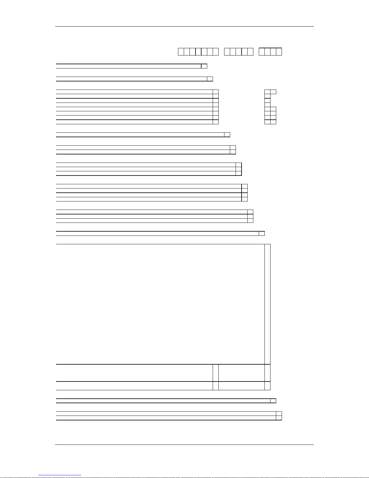
Table 1-1: 7SR224 Ordering Options.......................................................................................................8
Table 2-1 Summary of Controller Relay Configurations ....................................................................10
Table 6-1 Operation Mode......................................................................................................................64
Symbols and Nomenclature
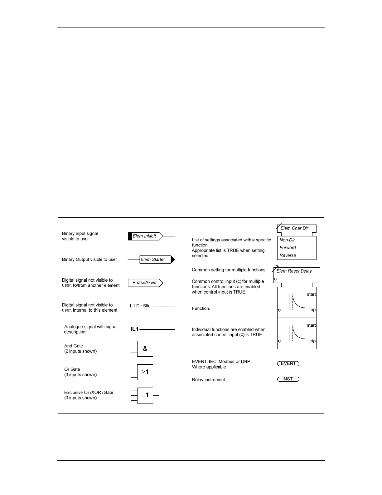
The following notational and formatting conventions are used within the remainder of this
document:
• Setting Menu Location MAIN MENU>SUB-MENU
• Setting: Elem name -Setting
• Setting value: value
• Alternatives: [1st] [2nd] [3rd]
Page 7
(1) Description of Operation 7SR224
©2009 Siemens Protection Devices Limited Page 7 of 66
Section 1: Introduction
This manual is applicable to the following relays:
• 7SR224 Directional Overcurrent and Directional Earth Fault Recloser Control Relay
The 7SR224 relay integrates the protection and control elements required to provide a complete
recloser control relay.
The ‘Ordering Options’ Tables summarise the features available in each model
General Safety Precautions
1.1 CURRENT TRANSFORMER CIRCUITS
The secondary circuit of a live CT must not be open circuited. Non-observance of this precaution can
result in injury to personnel or damage to equipment.
1.2 EXTERNAL RESISTORS
Where external resistors are fitted to relays, these may present a danger of electric shock or burns, if
touched.
1.3 FIBRE OPTIC COMMUNICATION
Where fibre optic communication devices are fitted, these should not be viewed directly. Optical
power meters should be used to determine the operation or signal level of the device.
1.4 FRONT COVER
The front cover provides additional securing of the relay element within the case. The relay cover
should be in place during normal operating conditions.
1.5 FRONT FASCIA
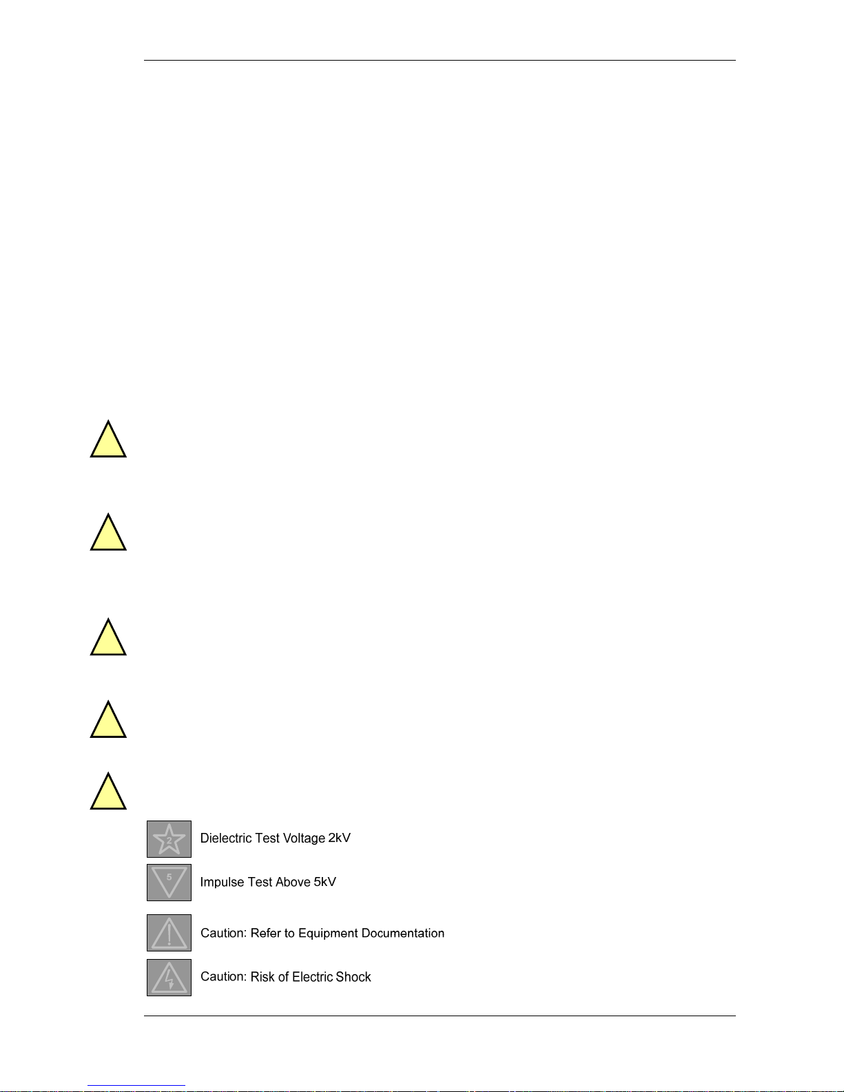
For safety reasons the following symbols are displayed on the fascia
!
!
!
!
!
Page 8
(1) Description of Operation 7SR224
Page 8 of 66 ©2009 Siemens Protection Devices Limited
1 2 3 4 5 6 7 8 9 101112 13141516
ORDER-No.:
7SR224 -2 -0
||| ||||| ||||
Protection Product Family
5
|| ||||| ||||
Overcurrent - Directional 2
|| ||||| ||||
|| ||||| ||||
Relay Type
6
| ||||| ||||
Recloser 4
| ||||| ||||
| ||||| ||||
Case, I/O and Fascia
1)
7
|||||||||
E10 case, 4 CT, 6 VT, 13 Binary Inputs / 14 Binary Outputs, 8 LEDs + 12 keys
1
||||| |DA|
E10 case, 4 CT, 4 VT, 13 Binary Inputs / 14 Binary Outputs, 8 LEDs + 12 keys
2
||||| |C||
E10 case, 4 CT, 4 VT, 23 Binary Inputs / 22 Binary Outputs, 8 LEDs + 12 keys
3
||||| |C||
E10 case, 4 CT, 4 VT, 33 Binary Inputs / 14 Binary Outputs, 8 LEDs + 12 keys
4
||||| |C||
E10 case, 4 CT, 6 VT, 23 Binary Inputs / 22 Binary Outputs, 8 LEDs + 12 keys
5
||||| |DA|
E12 case, 4 CT, 4 VT, 33 Binary Inputs / 14 Binary Outputs, 16 LEDs + 12 keys
6
||||| |
C/E A
|
E12 case, 4 CT, 4 VT, 33 Binary Inputs / 30 Binary Outputs, 16 LEDs + 12 keys
7
||||| |
C/E A
|
E12 case, 4 CT, 4 VT, 43 Binary Inputs / 22 Binary Outputs, 16 LEDs + 12 keys
8
||||| |
C/E A
|
||||| ||||
Measuring Input
8
|||| ||||
1/5 A, 63.5/110V
2
|||| ||||
|||| ||||
Auxiliary Nominal Voltage
9
||| ||||
30 to 220V DC, binary input threshold 19V DC 22W A
||| ||||
30 to 220V DC, binary input threshold 88V DC 22W B
||| ||||
||| ||||
Region Specific Functions
10
|| ||||
Region World, 50/60Hz, language Engl ish, Reyrolle fascia A
|| ||||
Region World, 50/60Hz, language English , Siemens fascia
B
|| ||||
Region USA, 60/50Hz, language English - US (ANSI) (language chang eable), Siemens fascia
C
|| ||||
|| ||||
Communication Interface
11
| ||||
Standard version - included in all models, USB front p ort, RS485 rear port
1
| ||||
Standard version - plus additional rear F/O ST connec tors (x2) and IRIG-B
2
| ||||
Standard version - plus additional rear RS485 and IRI G-B
3
| ||||
Standard version - plus additional rear RS232 and IRI G-B
4
| ||||
| ||||
Protocol
12
||||
IEC 60870-5-103
0
||||
IEC 60870-5-103 and Modbus RTU (user selectable setting)
1
||||
IEC 60870-5-103 and Modbus RTU and DNP 3.0 (user selectable setting)
2
||||
||||
Spare
13
|||
0
|||
|||
Protection Function Packages
14
||
Standard version - included in all models C
||
27/59 Under/overvoltage
||
27/59 Under/overvoltage, Sag/swell
||
37 Undercurrent
||
46BC Broken conductor/load unbalance
||
46NPS Negative phase sequence overcurrent
||
47NPS Negative phase sequence overvoltage
||
49 Thermal overload
||
50BF Circuit bre aker fail
||
51V Voltage dependent overcurrent
||
59N Neutral voltage displacement
||
60CTS CT supervision
||
60VTS VT supervision
||
67/50 Directional instantaneous phase fault overcurrent
||
67/50G Directional in stantaneous earth fault
||
67/51 Directional time delayed phase fault overcurrent
||
67/51G Directional tim e delayed earth fault
||
67/50HIZ Directional instantaneous sensitive earth fault
||
67/51HIZ Directional time delayed sensitive earth fault
||
74TC Trip circuit supervision
||
74BF Circuit bre aker close fail
||
79 Autoreclose
||
81 Under/overfrequency
||
81HBL2 Inrush restraint
||
86 Lockout
||
Battery and capacitor test
||
Cold load pickup
||
Programmable logic
||
Standard version - plus
D
||
27/59 Under/overvoltage
||
60VTS VT supervision
||
Loop automation by loss of voltage
||
Standard version - plus
E
||
Single/triple pole autoreclose
||
||
Additional Functionality
15
|
No additional functionality
A
|
|
Settings File
16
Standard settings and standard labels for Si emens Recloser 0
Standard settings and standard labels for an y third party Recloser 2
1)
4CT is configured as 3PF + EF/SEF (user selectable setting).
6-8
1,5
Table 1-1: 7SR224 Ordering Options
Page 9
(1) Description of Operation 7SR224
©2009 Siemens Protection Devices Limited Page 9 of 66
7SR224
46
BC
46
NPS
(x2)
37
(x2)
49
50
BF
51V
V
L1
(VA)
V
L2
(VB)
V
L3
(VC)
V
4
(VX)
I
L1
(IA)
81
HBL
2
37
(x2)
49
50
BF
51V
I
L2
(IB)
81
HBL
2
37
(x2)
49
50
BF
51V
I
L3
(IC)
81
HBL
2
60
CTS60VTS
I
4
(IG/I
SEF
)
74
TCS
(x3)
NOTE: The use of some
functions are mutually exclusive
67/
50
(x4)
67/
51
(x4)
67/
50
(x4)
67/
50
(x4)
67/
51
(x4)
67/
51
(x4)
64
H
27
59
27
59
(x4)
27
59
(x4)
27
59
(x4)
47
(x2)
79
59N
(x2)
Note:
Example shows
Voltage Config =
Van, Vbn, Vcn
81
(x4)
67/
50G
(x4)
67/
51G
(x4)
67/
50S
(x4)
67/
51S
(x4)
27S
59S
27S
59S
27S
59S
Batt
Test
Cap.
Test
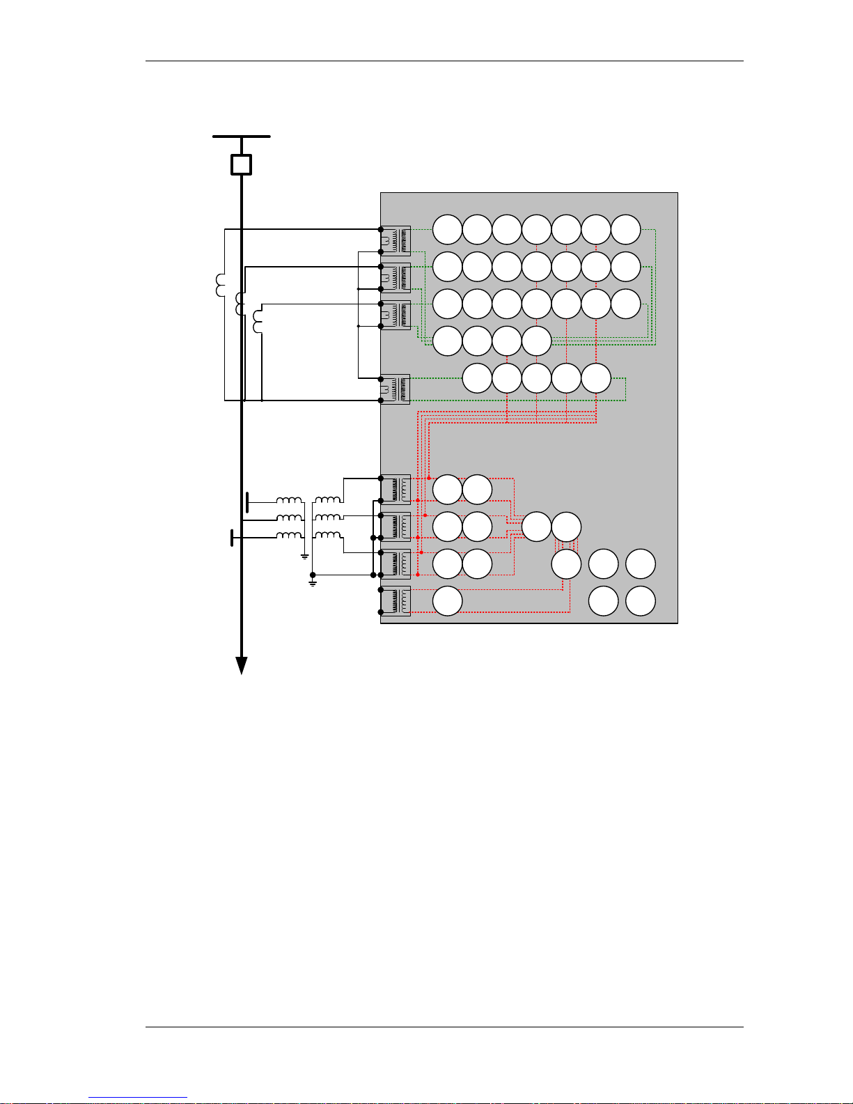
Figure 1.5-1 Functional Diagram of 7SR224 Relay Showing Possible External Connections
Page 10

(1) Description of Operation 7SR224
Page 10 of 66 ©2009 Siemens Protection Devices Limited
Section 2: Hardware Description
2.1 GENERAL
The structure of the relay is based upon the Multi-function hardware platform. The relays are supplied
in a size E10 or E12 case (where 1 x E = width of approx. 26mm). The hardware design provides
commonality between products and components across the Multi-function range of relays.
Table 2-1 Summary of Controller Relay Configurations
Relay Current
Inputs
Voltage
Inputs
Binary
Inputs
Output
Relays
LEDs Function
Keys
Case
7SR2241 4 6 13 14 8 12 E10
7SR2242 4 4 13 14 8 12 E10
7SR2243 4 4 23 22 8 12 E10
7SR2244 4 4 33 14 8 12 E10
7SR2245 4 6 23 22 8 12 E10
7SR2246 4 4 33 14 16 12 E12
7SR2247 4 4 33 30 16 12 E12
7SR2248 4 4 43 22 16 12 E12
Relays are assembled from the following modules:
1) Front Fascia with three fixed function LEDs, Function Keys and ordering options of configurable
LEDs.
2) Processor module.
3) Analogue Input module - 4 x Current + 4 or 6 x Voltage.
4) Power Supply (PSU) and Basic Binary Input (BI) and Binary Output (BO).
5) Binary Input/Output Module.
6) Data Comms module (optional)
2.2 CASE
The relays are housed in cases designed to fit directly into standard panel racks. The case has a width
of 260mm (E10), 312mm (E12) and a height of 177 mm (4U). The required panel depth for wiring
clearance is 242 mm and 287mm to accommodate the bending radius of fibre optic data
communications cables if fitted.
The complete relay assembly is withdrawable from the front of the case. Shorting contacts on the rear
connection block in the case ensure that the CT circuits remain short-circuited when the relay is
removed.
External connections to the rear terminal block are made via M4 screws. Each terminal can accept two
4mm crimps.
Page 11
(1) Description of Operation 7SR224
©2009 Siemens Protection Devices Limited Page 11 of 66
Located at the top rear of the case is a screw clamp earthing point, this must be connected to the main
panel earth.
2.3 FRONT COVER
With the transparent front cover in place the user only has access to the READ DOWN ▼ and
TEST/RESET► buttons, via blue push buttons, allowing all areas of the menu system to be viewed,
but preventing setting changes and control actions. The only ‘action’ that is permitted is to reset the
Fault Data display, latched binary outputs and LEDs by using the TEST/RESET button. The front
cover is used to secure the relay assembly in the case.
2.4 POWER SUPPLY UNIT (PSU)
The relay PSU can be directly connected to any dc supply via a suitably rated fuse from 30V dc to
220V dc.
In the event of the supply voltage level falling below the relay minimum operate level the PSU will
automatically switch itself off and latch out – this prevents any PSU overload conditions occurring. The
PSU is reset by switching the auxiliary supply off and on.
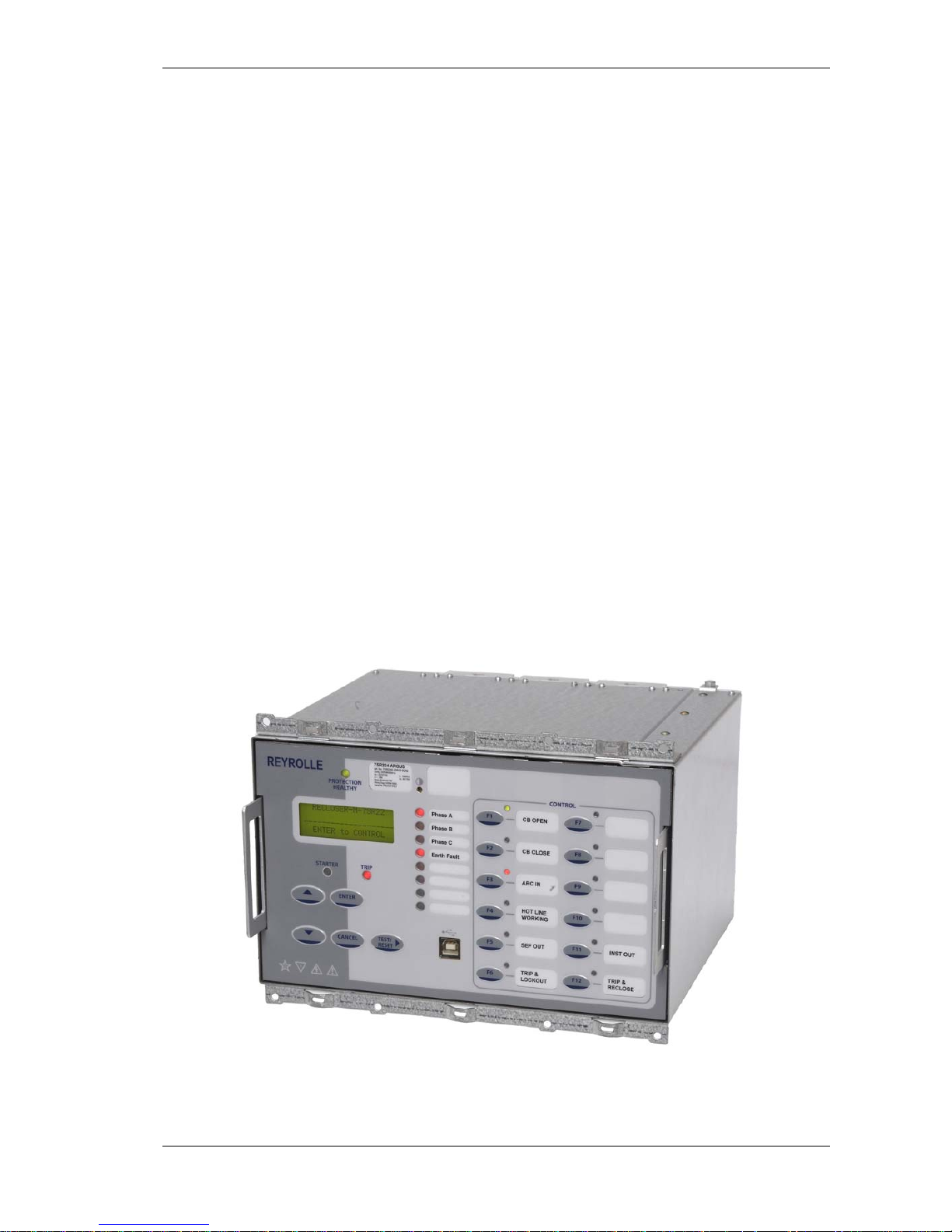
2.5 OPERATOR INTERFACE/ FASCIA
The operator interface is designed to provide a user-friendly method of controlling, entering settings
and retrieving data from the relay.
Figure 2.5-1 7SR224 with 12 Function Keys and 3 + 8 LEDs in E10 Case
NOTE: Transparent cover with pushbuttons not shown
Page 12

(1) Description of Operation 7SR224
Page 12 of 66 ©2009 Siemens Protection Devices Limited
The fascia is an integral part of the relay. Handles are located at each side of the relay which allow it
to be withdrawn from the relay case.
Relay Information
Above the LCD three labels are provided, these provide the following information:
1) Product name and order code.
2) Nominal current rating, rated frequency, voltage rating, auxiliary dc supply rating, binary
input supply rating, configuration and serial number.
3) Blank label for user defined information.
A ‘template’ is available to allow users to create and print customised labels.
Liquid Crystal Display (LCD)
A 4 line by 20-character liquid crystal display indicates settings, instrumentation, fault data and control
commands.
To conserve power the display backlighting is extinguished when no buttons are pressed for a user
defined period. A setting within the “SYSTEM CONFIG” menu allows the timeout to be adjusted from 1
to 60 minutes and “Off” (backlight permanently on). After an hour the display is completely deactivated. Pressing any key will re-activate the display.
The LCD contrast can be adjusted using a flat blade screwdriver to turn the screw located below the
contrast symbol
. Turning the screw clockwise increases the contrast, anti-clockwise reduces the
contrast.
‘PROTECTION HEALTHY’ LED
This green LED is steadily illuminated to indicate that DC voltage has been applied to the relay power
supply and that the relay is operating correctly. If the internal relay watchdog detects an internal fault
then this LED will continuously flash.
‘PICKUP’ LED
This yellow LED is illuminated to indicate that a user selectable function(s) has picked up. The LED
will self reset after the initiating condition has been removed.
Functions are assigned to the PICKUP LED in the OUTPUT CONFIG>PICKUP CONFIG menu.
‘TRIP’ LED
This red LED is steadily illuminated to indicate that a user selectable function has operated to trip the
circuit breaker. Functions are assigned to the ‘Trip’ LED using the OUTPUT CONFIG>Trip Contacts
setting.
Operation of the LED is latched and can be reset by either pressing the TEST/RESET► button,
energising a suitably programmed binary input, or, by sending an appropriate command over the data
communications channel(s).
Indication LEDs
Relays have either 8 or 16 user programmable LED indicators. Each LED can be programmed to be
illuminated as either green, yellow or red. Where an LED is programmed to be lit both red and green it
will illuminate yellow.
Functions are assigned to the LEDs in the OUTPUT CONFIG>OUTPUT MATRIX menu.
Each LED can be labelled by withdrawing the relay and inserting a label strip into the pocket behind
the front fascia. A ‘template’ is available to allow users to create and print customised legends.
Page 13

(1) Description of Operation 7SR224
©2009 Siemens Protection Devices Limited Page 13 of 66
Each LED can be user programmed as hand or self –resetting. Hand reset LEDs can be reset by
either pressing the TEST/RESET► button, energising a suitably programmed binary input, or, by
sending an appropriate command over the data communications channel(s).
The status of hand reset LEDs is maintained by a back up storage capacitor in the event of an
interruption to the d.c. supply voltage.
Standard Keys
The relay is supplied as standard with five navigation / control pushbuttons and 12 programmable
function keys. The navigation / control buttons are used to navigate the menu structure and control
relay functions. They are labelled:
▲ Increases a setting or moves up menu.
▼ Decreases a setting or moves down menu.
TEST/RESET► Moves right, can be used to reset selected functionality and for LED
test (at relay identifier screen).
ENTER Used to initiate and accept settings changes.
CANCEL. Used to cancel settings changes and/or move up the menu structure
by one level per press.
NOTE: All settings and configuration of LEDs, BI, BO and function keys can be accessed and set by
the user using these keys. Alternatively configuration/settings files can be loaded into the relay using
‘Reydisp’.
Function Keys/ LEDs
The 12 programmable function keys can be configured by the user to initiate selected functions from
the Control menu (INPUT CONFIG > FUNCTION KEY MATRIX).
Each programmable function key has an associated LED. These can be programmed as hand or self
reset and can be illuminated as green, yellow or red (OUTPUT CONFIG > LED CONFIG).
Function keys can be used with Quick Logic.
2.6 CURRENT INPUTS
Four current inputs are provided on the Analogue Input module. Terminals are available for both 1A
and 5A inputs.
Current is sampled at 32 samples per cycle (1600Hz) for both 50Hz and 60Hz system frequencies.
Protection and monitoring functions of the relay use either the Fundamental Frequency RMS or the
True RMS value of current appropriate to the individual function.
The waveform recorder samples and displays current input waveforms at 32 samples per cycle
(1600Hz).
2.7 VOLTAGE INPUTS
Four voltage inputs are provided on the Analogue Input module.
Voltage is sampled at 32 samples per cycle (1600Hz) both 50Hz and 60Hz system frequencies.
Protection and monitoring functions of the relay use fundamental frequency voltage measurement.
The waveform recorder samples and displays voltage input waveforms at 32 samples per cycle
(1600Hz).
Page 14
(1) Description of Operation 7SR224
Page 14 of 66 ©2009 Siemens Protection Devices Limited
NB: The Relay has a flat frequency response measuring harmonic currents up to and including the
50th Harmonic but does not measure the content at the aliasing frequencies i.e. 800 Hz (16
th
harmonic) + 1600 Hz (32
nd
harmonic) + 2400 Hz (48th harmonic).
2.8 BINARY INPUTS
The binary inputs are operated from a suitably rated dc supply.
Relays are fitted with 13, 33 or 43 binary inputs (BI) depending on the variant. The user can assign
any binary input to any of the available functions (INPUT CONFIG > INPUT MATRIX).
The Power Supply module includes the relay basic I/O incorporating 3 x BI and 6 x BO.
Pick-up (PU) and drop-off (DO) time delays are associated with each binary input. Where no pick-up
time delay has been applied the input may pick up due to induced ac voltage on the wiring
connections (e.g. cross site wiring). The default pick-up time of 20ms provides ac immunity. Each input
can be programmed independently.
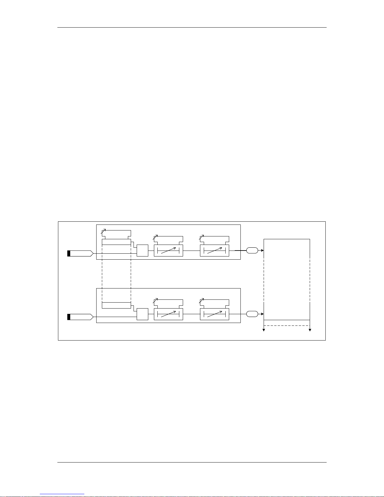
Each input may be logically inverted to facilitate integration of the relay within the user scheme. When
inverted the relay indicates that the BI is energised when no d.c. is applied. Inversion occurs before
the PU & DO time delay, see fig. 2.8-1.
Each input may be mapped to any front Fascia indication LED and/or to any Binary output contact and
can also be used with the internal user programmable logic. This allows the relay to provide panel
indications and alarms.
Event
BI 1
Binary Input 1
=1
Inverted Inputs
BI 1 inverted
BI 1 P/U Delay
Event
BI n
Binary Input n
=1
BI n inverted
BI n P/U Delay
INPUT CONFIG>
INPUT MATRIX
(Or gates)
Logic signals,
e.g. '51-1 Inhibit '
BI 1 D/O Delay
BI n D/O Delay
INPUT
CONFIG>
BINARY
INPUT
CONFIG
Figure 2.8-1 Binary Input Logic
Page 15

(1) Description of Operation 7SR224
©2009 Siemens Protection Devices Limited Page 15 of 66
2.9 BINARY OUTPUTS (OUTPUT RELAYS)
Relays are fitted with 14, 22 or 30 binary outputs. All outputs are fully user configurable and can be
programmed to operate from any or all of the available functions.
The Power Supply module includes the relay basic I/O. The module includes six binary outputs each
fitted with 1 contact – providing in total 1 x normally closed (NC), 2 x change-over (CO) and 3 x
normally open (NO) contacts.
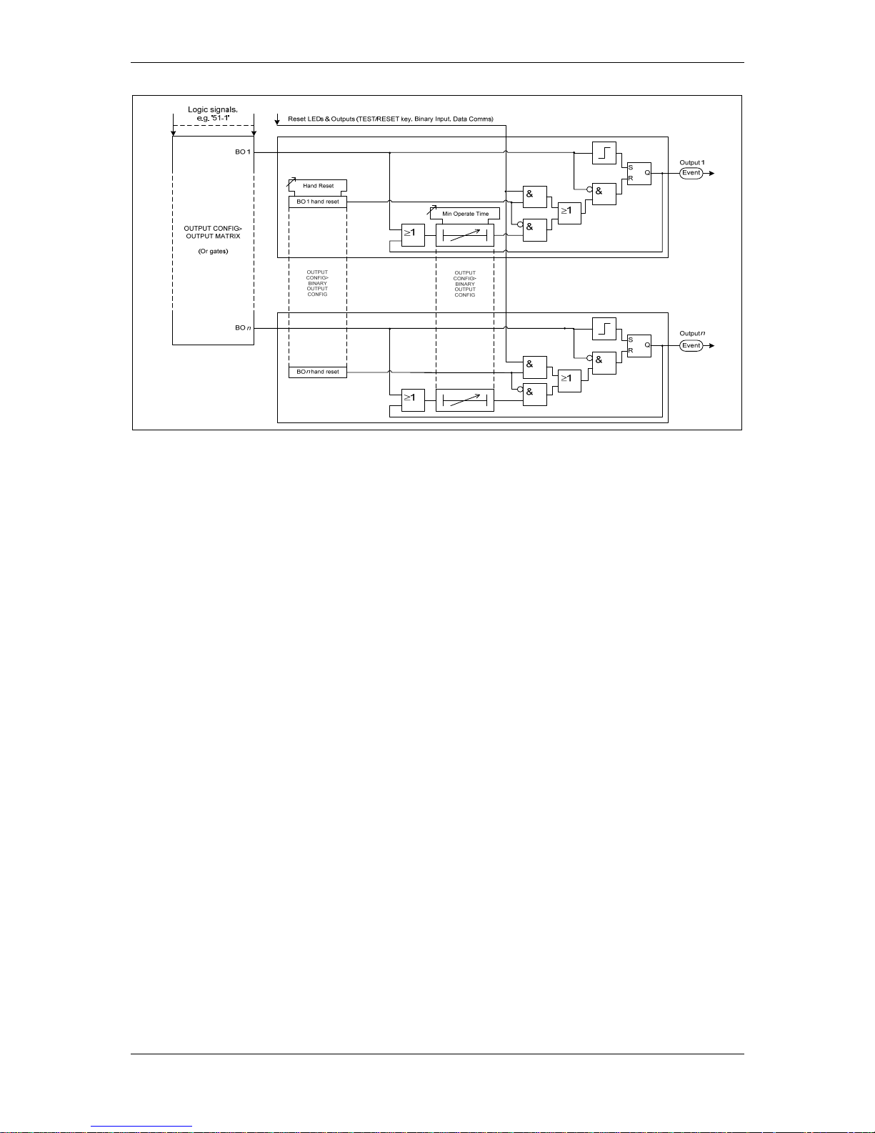
In the default mode of operation binary outputs are self reset and remain energised for a user
configurable minimum time of up to 60 seconds. If required, outputs can be programmed to operate as
‘hand reset’. Alternatively, outputs can be programmed as ‘Pulsed’ outputs. When operated, these
outputs will reset automatically after a delay of the minimum operating time.
The binary outputs can be used to operate the trip coils of the circuit breaker directly where the trip coil
current does not exceed the 'make and carry' contact rating. The circuit breaker auxiliary contacts or
other in-series auxiliary device must be used to break the trip coil current.
When the relay is withdrawn from the case all normally closed contacts will be open circuited. This
should be considered in the design of the control and protection circuitry.
Notes on Pulsed Outputs
When operated, the output will reset after a user configurable time of up to 60 seconds regardless of
the initiating condition.
Notes on Self Reset Outputs
Self reset operation has a minimum reset time of 100ms
With a failed breaker condition the relay may remain operated until current flow is interrupted by an
upstream device. The relay will then reset and attempt to interrupt trip coil current flowing through an
output contact. Where this level is above the break rating of the output contact an auxiliary relay with
heavy-duty contacts should be utilised.in the primary system
Notes on Hand Reset Outputs
Hand reset outputs can be reset by either pressing the TEST/RESET► button, by energising a
suitably programmed binary input, or, by sending an appropriate command over the data
communications channel(s).
On loss of the auxiliary supply hand-reset outputs will reset. When the auxiliary supply is reestablished the binary output will remain in the reset state unless the initiating condition is still present.
Page 16
(1) Description of Operation 7SR224
Page 16 of 66 ©2009 Siemens Protection Devices Limited
Figure 2.9-1 Binary Output Logic
2.10 VIRTUAL INPUT/OUTPUTS
The relays have 16 virtual input/outputs, these are internal logic states. Virtual I/O is assigned in the
same way as physical Binary Inputs and Binary Outputs. Virtual I/O is mapped from within the INPUT
CONFIG > INPUT MATRIX and OUTPUT CONFIG > OUTPUT MATRIX menus.
2.11 SELF MONITORING OF THE CONTROLLER
The relay incorporates a number of self-monitoring features. Each of these features can initiate a
controlled reset recovery sequence.
Supervision includes a power supply watchdog, code execution watchdog, memory checks by
checksum and processor/ADC health checks. When all checks indicate the relay is operating correctly
the ‘Protection Healthy’ LED is illuminated.
If an internal failure is detected, a message will be displayed; also an event will be generated and
stored. The relay will reset in an attempt to rectify the failure. This will result in de-energisation of any
binary output mapped to ‘protection healthy’ and flashing of the protection healthy LED. If a successful
reset is achieved by the relay the LED and output contact will revert back to normal operational mode,
and the relay will restart.
2.11.1 Protection Healthy/Defective
When the relay has an auxiliary DC supply and it has successfully passed its self-checking procedure
then the front facia Protection Healthy LED is turned on.
A normally open contact can be mapped via the binary output matrix to provide an external protection
healthy signal.
A normally closed contact can be mapped via the binary output matrix to provide an external
protection defective signal. With the ‘Protection Healthy’ this contact is open. When the auxiliary DC
supply is not applied to the relay or a problem is detected within the relay then this output contact
closes to provide external indication.
A shorting contact in the case at positions 25-26 of the PSU module can be used to provide an
external indication when the relay is withdrawn.
Page 17

(1) Description of Operation 7SR224
©2009 Siemens Protection Devices Limited Page 17 of 66
2.12 BATTERY AND CAPACITOR TEST FACILITY OF THE RECLOSER
The quiescent battery voltage V
AUX
is constantly monitored to ensure that the charging system is
connected and operating correctly. The capacitor voltage is monitored externally by the Switch Unit
Driver and Monitor. The healthy condition of the capacitor is indicated to the Controller by the state of
two binary signals. These signals are constantly monitored and used to provide alarms and operation
blocking for quiescent capacitor voltage levels which are out of limits.
Battery and capacitor tests are initiated at user set intervals - typically once per week/month. The
condition and state of the Recloser battery and Recloser capacitor are assessed; any unhealthy states
are identified and can be alarmed. Battery and capacitor tests are not carried out at the same time.
The battery test is initiated first to avoid any possible interaction with the capacitor test which is
performed 30 minutes afterwards.
Page 18

(1) Description of Operation 7SR224
Page 18 of 66 ©2009 Siemens Protection Devices Limited
Section 3: Protection Functions
3.1 CURRENT PROTECTION: PHASE OVERCURRENT (67, 51, 50)
All phase overcurrent elements have a common setting to measure either fundamental frequency
RMS or True RMS current:
True RMS current: 51/50 Measurement = RMS
Fundamental Frequency RMS current: 51/50 Measurement = Fundamental
3.1.1 Directional Control of Overcurrent Protection (67)
The directional element produces forward and reverse outputs for use with overcurrent elements.
These outputs can then be mapped as controls to each shaped and instantaneous over-current
element.
If a protection element is set as non-directional then it will operate independently of the output of the
directional detector. However, if a protection element is programmed for forward directional mode then
operation will occur only for a fault lying within the forward operate zone. Conversely, if a protection
element is programmed for reverse directional mode then operation will occur only for a fault lying
within the reverse operate zone. Typically the forward direction is defined as being ‘away’ from the
busbar or towards the protected zone.
The Characteristic angle is the phase angle by which the polarising voltage must be adjusted such
that the directional detector gives maximum sensitivity in the forward operate zone when the current is
in phase with it. The reverse operate zone is the mirror image of the forward zone.
Voltage polarisation is achieved for the phase-fault elements using the quadrature voltage i.e. at unity
power factor I leads V by 90
°
. Each phase current is compared to the voltage between the other two
phases:
I
L1
~ V23 IL2 ~ V31 I
L3
~ V12
The characteristic angle can be user programmed to any angle between -95° and +95° using the 67
Char Angle setting. The voltage is the reference phasor (V
ref
) and the 67 Char Angle setting is added
to this to adjust the forward and reverse zones.
The centre of the forward zone is set by (V
ref
Angle + 67 Char Angle) and should be set to correspond
with I
fault
Angle for maximum sensitivity i.e.
For fault current of -60
°
(I lagging V by 60
°
) a 67 Char Angle of +30
°
is required for maximum
sensitivity (i.e. due to quadrature connection 90
°
- 60° = 30°).
OR
For fault current of -45
°
(I lagging V by 45
°
) a 67 Char Angle of +45
°
is required for maximum
sensitivity (i.e. due to quadrature connection 90
°
- 45° = 45°).
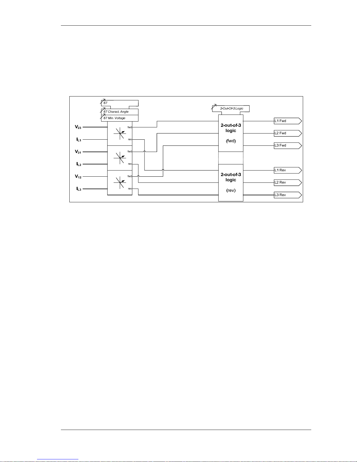
Two-out-of-three Gate
When the 67 2-Out-Of-3 Logic setting is set to Enabled, the directional elements will only operate for
the majority direction, e.g. if I
L1
and IL3 are detected as forward flowing currents and IL2 is detected as
reverse current flow, phases L1 and L3 will operate forwards, while phase L2 will be inhibited.
Page 19
(1) Description of Operation 7SR224
©2009 Siemens Protection Devices Limited Page 19 of 66
Minimum Polarising Voltage
The 67 Minimum Voltage setting defines the minimum polarising voltage level. Where the measured
polarising voltage is below this level no directional output is given and operation of protection elements
set as directional will be inhibited. This prevents mal-operation under fuse failure/MCB tripped
conditions where noise voltages can be present.
Figure 3.1-1 Logic Diagram: Directional Overcurrent Eleme n t (67)
Page 20
(1) Description of Operation 7SR224
Page 20 of 66 ©2009 Siemens Protection Devices Limited
3.1.2 Instantaneous Overcurrent Protection (50)
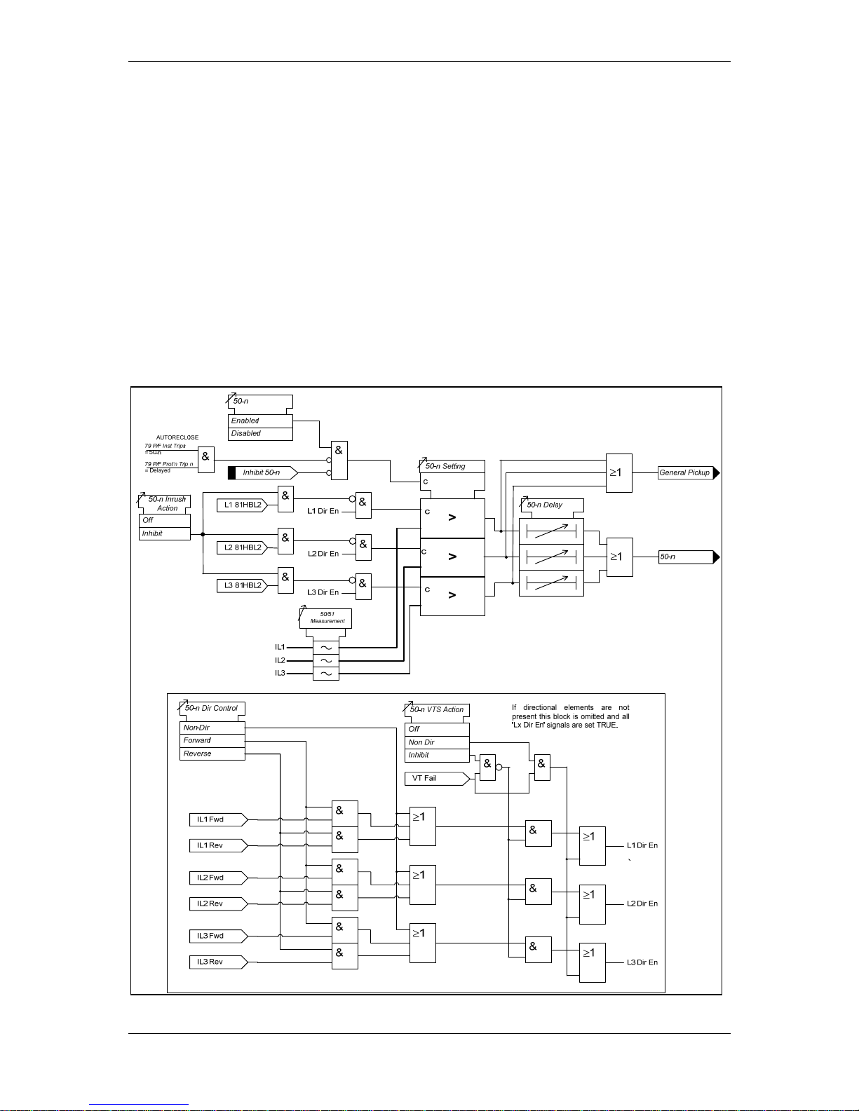
Four elements are provided e.g. giving the option of using two elements set to forward and two to
reverse.
Each instantaneous element (50-n) has independent settings. 50-n Setting for pick-up current and 50-
n Delay follower time delay. The instantaneous elements have transient free operation.
For the directional elements the direction of operation can be set using 50-n Dir. Control setting.
Directional logic is provided independently for each 50-n element.
Operation of the instantaneous overcurrent elements can be inhibited from:
Inhibit 50-n A binary or virtual input, or function key.
79 P/F Inst Trips: 50-n When ‘delayed’ trips only are allowed in the auto-reclose
sequence (79 P/F Prot’n Trip n = Delayed).
50-n Inrush Action: Inhibit Operation of the inrush current detector function.
50-n VTS Action: Inhibit Operation of the VT Supervision function.
Figure 3.1-2 Logic Diagram: Instantaneous Over-current Element
Page 21

(1) Description of Operation 7SR224
©2009 Siemens Protection Devices Limited Page 21 of 66
3.1.3 Time Delayed Overcurrent Protection (51)
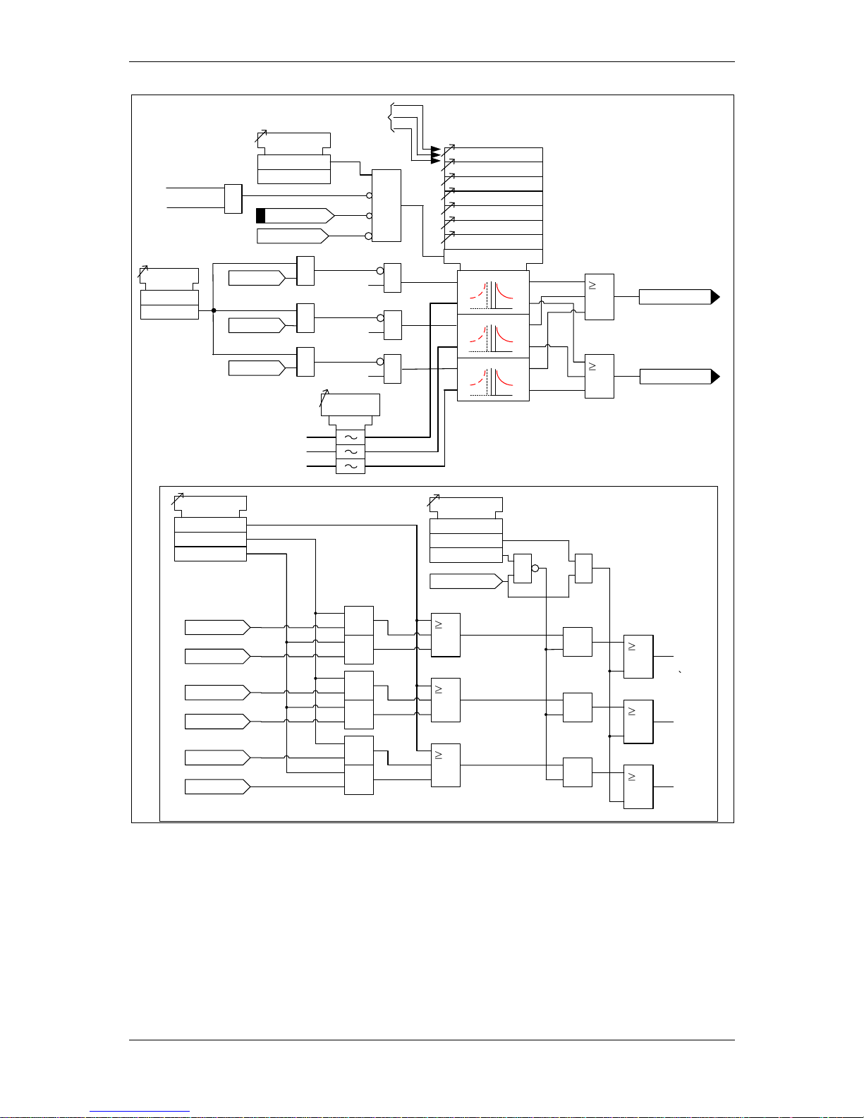
Four elements are provided e.g. giving the option of using two elements set to forward and two to
reverse.
51-n Setting sets the pick-up current level. Where the voltage controlled overcurrent function (51VCO)
is used a multiplier is applied to this setting where the voltage drops below the setting VCO Setting,
see section 3.2.
A number of shaped characteristics are provided. An inverse definite minimum time (IDMT)
characteristic is selected from IEC, ANSI or manufacturer specific curves using 51-n Char. A time
multiplier is applied to the characteristic curves using the 51-n Time Mult setting. Alternatively, a
definite time lag delay (DTL) can be chosen using 51-n Char. When Delay (DTL) is selected the time
multiplier is not applied and the 51-n Delay (DTL) setting is used instead. The full list of operating
curves is given in section 2 – ‘Settings, Configuration and Instruments Guide’. Operating curve
characteristics are illustrated in section 3 – ‘Performance Specification’.
The 51-n Reset setting can apply a definite time delayed reset, or when configured as an ANSI
characteristic an ANSI (DECAYING) reset. If ANSI (DECAYING) reset is selected for an IEC
characteristic, the reset will be instantaneous. The reset mode is significant where the characteristic
has reset before issuing a trip output – see ‘Applications Guide’.
A minimum operate time for the characteristic can be set using 51-n Min. Operate Time setting.
A fixed additional operate time can be added to the characteristic using 51-n Follower DTL setting.
For the directional elements the direction of operation can be set using 51-n Dir. Control setting.
Directional logic is provided independently for each 51-n element.
Operation of the time delayed overcurrent elements can be inhibited from:
Inhibit 51-n A binary or virtual input, or function key
79 P/F Inst Trips: 51-n When ‘delayed’ trips only are allowed in the auto-reclose
sequence (79 P/F Prot’n Trip n = Delayed).
51c Activation of the cold load settings (see section 3.7).
51-n Inrush Action: Inhibit Operation of the inrush current detector function.
51-n VTSAction: Inhibit Operation of the VT Supervision function.
Page 22
(1) Description of Operation 7SR224
Page 22 of 66 ©2009 Siemens Protection Devices Limited
1
1
General Pickup
51-n
51-n Setting
51-n Charact
51-n Time Mult
51-n Delay (DTL)
51-n Reset
c
Forward
Reverse
51-n Dir Control
Non-Dir
1
&
&
1
&
&
1
&
&
51-n Follower DTL
L1 Dir En
L2 Dir En
L3 Dir En
L1 Dir En
L2 Dir En
L3 Dir En
IL1 Fwd
IL1 Rev
IL2 Fwd
IL2 Rev
IL3 Fwd
IL3 Rev
&
&
&
1
1
1
Non Dir
51-n VTS Action
Off
Inhibit
VT Fail
&
51-n Min. Operate Time
&
IL1
IL2
IL3
50/51
Measurement
&
See Voltage Controlled
Overcurrent (51V)
L1 81HBL2
51c
51-n Inrush
Action
Off
Inhibit
&
L3
L2
L1
L2 81HBL2
L3 81HBL2
&
&
&
&
&
c
Pickup
trip
c
Pickup
trip
c
Pickup
trip
Inhibit 51-n
51-n Element
Enabled
Disabled
&
79 P/F Inst Trips
= 51-n
79 P/F Prot’n Trip n
= Delayed
AUTORECLOSE
Figure 3.1-3 Logic Diagram: Time Delayed Overcurrent Element
Page 23
(1) Description of Operation 7SR224
©2009 Siemens Protection Devices Limited Page 23 of 66
3.2 CURRENT PROTECTION: VOLTAGE CONTROLLED OVERCURRENT (51V)
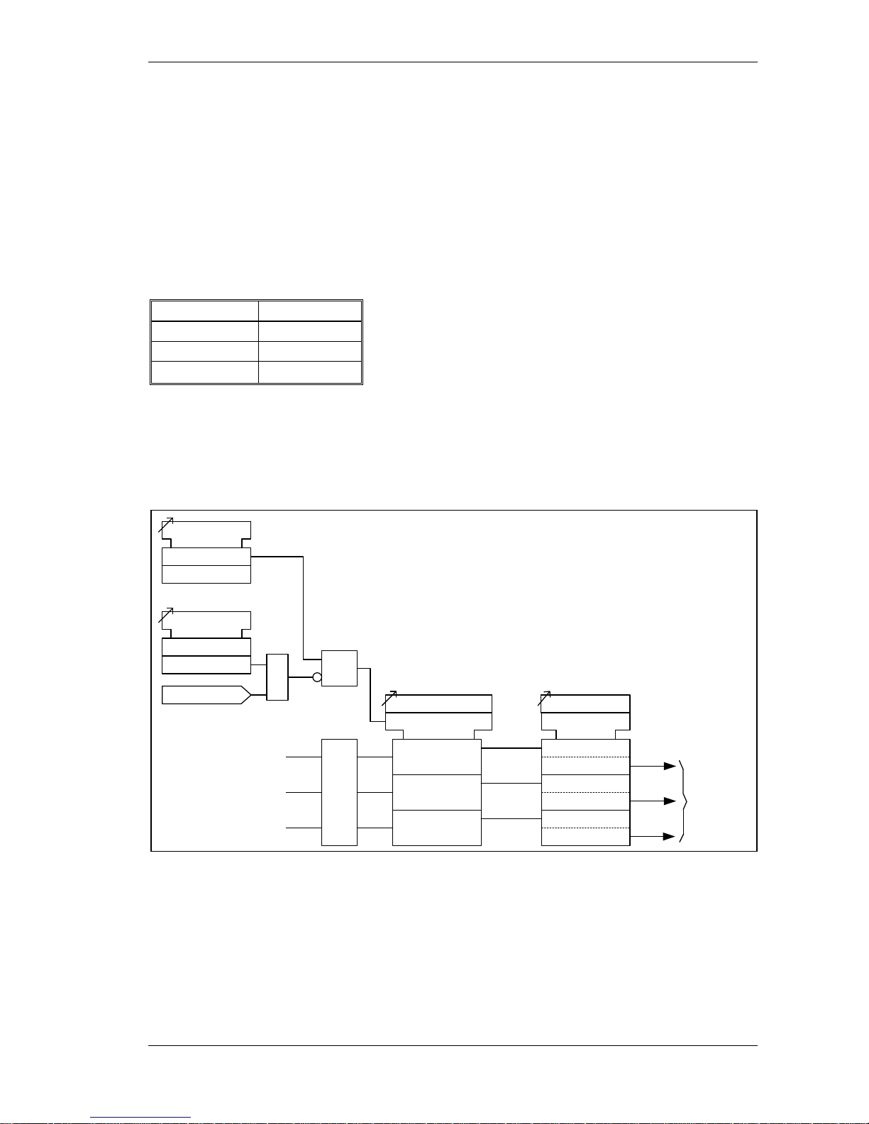
Each shaped overcurrent element 51-n Setting can be independently controlled by the level of
measured (control) input voltage.
For applied voltages above VCO Setting the 51-n element operates in accordance with its normal
current setting (see 3.1.3). For input Ph-Ph control voltages below VCO Setting a multiplier (51-n
Multiplier) is applied to reduce the 51-n pickup current setting.
51-n Multiplier is applied to each phase independently when its control phase-phase voltage falls
below VCO Setting. The voltage levels used for each phase over-current element are shown in the
table below. Relays with a Ph-N connection automatically calculate the correct Ph-Ph control voltage.
Current Element Control Voltage
IL1 V
12
IL2 V
23
IL3 V
31
The Voltage Controlled Overcurrent function (51V) can be inhibited from:
VCO VTSAction: Inhibit Operation of the VT Supervision function.
V
L1
51V Setting
c
&
51V Element
Enabled
Disabled
<
<
<
V
L2
V
L3
51V VTS Action
Off
Inhibit
See
Delayed
Overcurrent
(51-n)
VT Fail
&
51-n Multiplier
c
V
12
V
31
V
23
c
x IL1 51-n Setting
c
x IL2 51-n Setting
c
x IL3 51-n Setting
L3
L2
L1
Figure 3.2-1 Logic Diagram: Voltage Controlled Overcurrent Protection
Page 24

(1) Description of Operation 7SR224
Page 24 of 66 ©2009 Siemens Protection Devices Limited
3.3 CURRENT PROTECTION: MEASURED EARTH FAULT (67G, 51G, 50G)
The earth current is measured directly via a dedicated current analogue input.
All measured earth fault elements have a common setting to measure either fundamental frequency
RMS, True RMS current or the derived sum current:
True RMS current: 51/50 Measurement = RMS
Fundamental Frequency RMS current: 51/50 Measurement = Fundamental
Additionally these elements can be selected to operate on a Fundamental Frequency current which is
calculated from the sum of the phase currents, i.e. a Derived quantity. This option should only be used
when the fourth current input is required for connection of a Core Balance Current Transformer to
achieve very low earth fault sensitivity using the 50/51SEF elements.
51/50 Measurement = Calculated
3.3.1 Directional Control of Measured Earth Fault Protection (67G)
The directional element produces forward and reverse outputs for use with measured earth fault
elements. These outputs can be mapped as controls to each shaped and instantaneous element.
If a protection element is set as non-directional then it will operate independently of the output of the
directional detector. However, if a protection element is programmed for forward directional mode then
operation will occur only for a fault lying within the forward operate zone. Conversely, if a protection
element is programmed for reverse directional mode then operation will occur only for a fault lying
within the reverse operate zone. Typically the forward direction is defined as being ‘away’ from the
busbar or towards the protected zone.
The Characteristic angle is the phase angle by which the polarising voltage must be adjusted such
that the directional detector gives maximum sensitivity in the forward operate zone when the current is
in phase with it. The reverse operate zone is the mirror image of the forward zone.
The measured directional earth fault elements use zero phase sequence (ZPS) polarising.
Voltage polarisation is achieved for the earth-fault elements by comparison of the appropriate current
with its equivalent voltage:
I
0
~ V0
The characteristic angle can be user programmed to any angle between -95° and +95° using the 67G
Char Angle setting. The voltage is the reference phasor (V
ref
) and the 67G Char Angle setting is
added to this to adjust the forward and reverse zones.
The centre of the forward zone is set by (V
ref
Angle + 67G Char Angle) and should be set to
correspond with I
fault
Angle for maximum sensitivity e.g.
For fault current of -15
°
(I lagging V by 15
°
) a 67G Char Angle of -15
°
is required for maximum
sensitivity, OR
For fault current of -45
°
(I lagging V by 45
°
) a 67G Char Angle of -45
°
is required for maximum
sensitivity.
Minimum Polarising Voltage
The 67G Minimum Voltage setting defines the minimum polarising voltage level. Where the
measured polarising voltage is below this level no directional output is given and. Operation of
protection elements set as directional will be inhibited. This prevents mal-operation under fuse
failure/MCB tripped conditions where noise voltages can be present.
Page 25
(1) Description of Operation 7SR224
©2009 Siemens Protection Devices Limited Page 25 of 66
Figure 3.3-1 Logic Diagram: Measured Directional Earth Fault Protection
3.3.2 Instantaneous Measured Earth Fault Protection (50G)
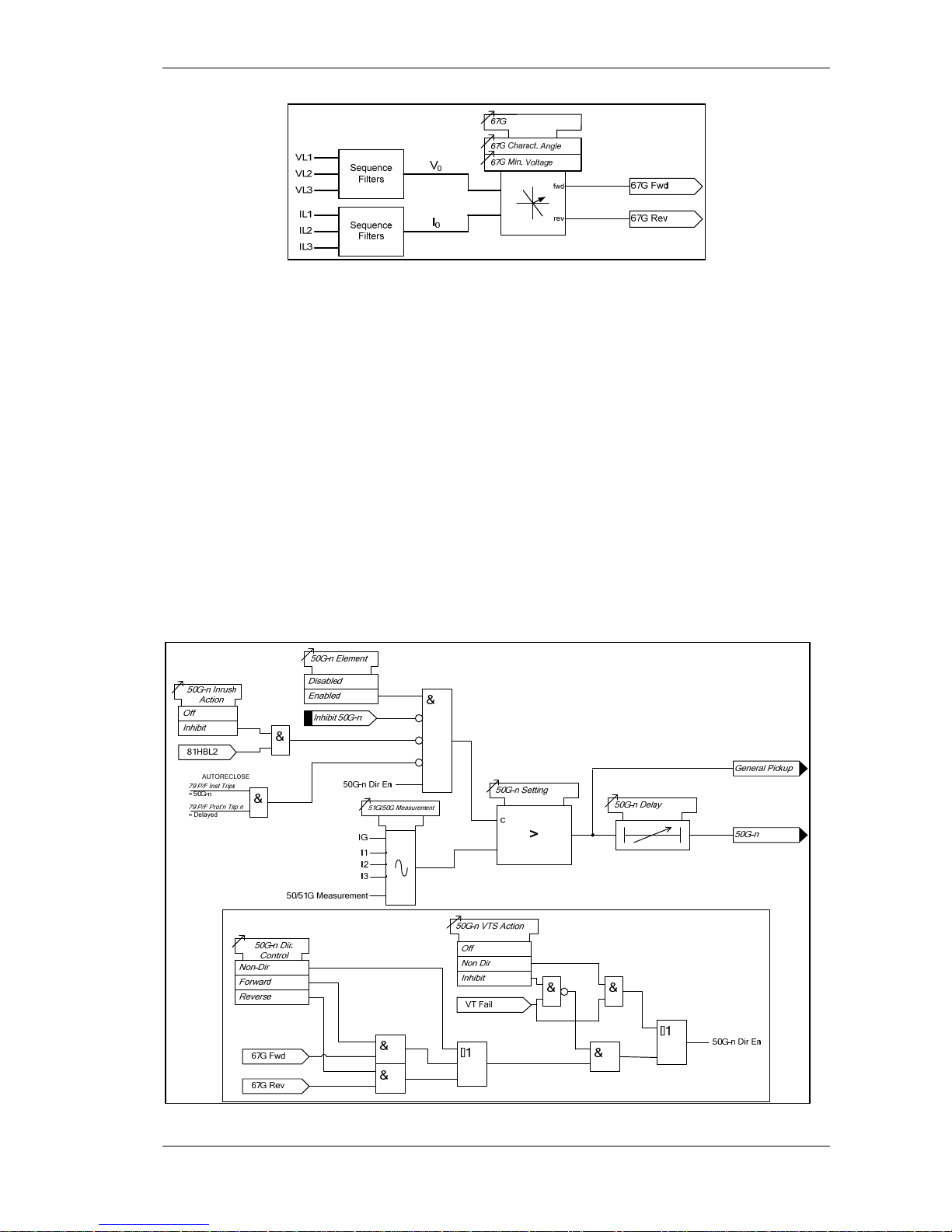
Four elements are provided e.g. giving the option of using two elements set to forward and two to
reverse.
Each instantaneous element has independent settings for pick-up current 50G-n Setting and a
follower time delay 50G-n Delay. The instantaneous elements have transient free operation.
For the directional elements the direction of operation can be set using 50G-n Dir. Control setting.
Directional logic is provided independently for each 50G-n element.
Operation of the instantaneous measured earth fault elements can be inhibited from:
Inhibit 50G-n A binary or virtual input, or function key
79 E/F Inst Trips: 50G-n When ‘delayed’ trips only are allowed in the auto-reclose
sequence (79 E/F Prot’n Trip n = Delayed).
50G-n Inrush Action: Inhibit Operation of the current inrush detector function.
50G-n VTSAction: Inhibit Operation of the VT Supervision function.
Figure 3.3-2 Logic Diagram: Measured Instantaneous Earth-fault Element
Page 26
(1) Description of Operation 7SR224
Page 26 of 66 ©2009 Siemens Protection Devices Limited
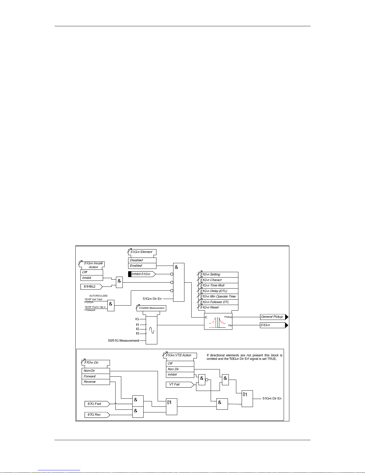
3.3.3 Time Delayed Measured Earth Fault Protection (51G)
Four elements are provided e.g. giving the option of using two elements set to forward and two to
reverse.
51G-n Setting sets the pick-up current level.
A number of shaped characteristics are provided. An inverse definite minimum time (IDMT)
characteristic is selected from IEC and ANSI curves using 51G-n Char. A time multiplier is applied to
the characteristic curves using the 51G-n Time Mult setting. Alternatively, a definite time lag (DTL)
can be chosen using 51G-n Char. When DTL is selected the time multiplier is not applied and the
51G-n Delay (DTL) setting is used instead. The full list of operating curves is given in section 2 –
‘Settings, Configuration and Instruments Guide’. Operating curve characteristics are illustrated in
section 3 – ‘Performance Specification’.
The 51G-n Reset setting can apply a definite time delayed reset, or when configured as an ANSI
characteristic an ANSI (DECAYING) reset. If ANSI (DECAYING) reset is selected for an IEC
characteristic, the reset will be instantaneous. The reset mode is significant where the characteristic
has reset before issuing a trip output – see ‘Applications Guide’.
A minimum operate time for the characteristic can be set using 51G-n Min. Operate Time setting.
A fixed additional operate time can be added to the characteristic using 51G-n Follower DTL setting.
For the directional elements the direction of operation can be set using 51G-n Dir. Control setting.
Directional logic is provided independently for each 51G-n element.
Operation of the time delayed measured earth fault elements can be inhibited from:
Inhibit 51G-n A binary or virtual input, or function key
79 E/F Inst Trips: 51G-n When ‘delayed’ trips only are allowed in the auto-reclose
sequence (79 E/F Prot’n Trip n = Delayed).
51G-n Inrush Action: Inhibit Operation of the inrush current detector function.
51G-n VTSAction: Inhibit Operation of the VT Supervision function.
Figure 3.3-3 Logic Diagram: Measured Time Dela yed Earth Fault Element (51 G)
Page 27
(1) Description of Operation 7SR224
©2009 Siemens Protection Devices Limited Page 27 of 66
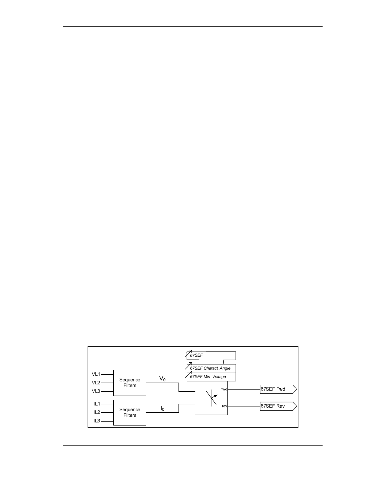
3.4 CURRENT PROTECTION: SENSITIVE EARTH FAULT (67SEF, 51SEF, 50SEF)
Current for the Sensitive Earth Fault (SEF) elements is measured directly via a dedicated current
analogue input. SEF elements measure the fundamental frequency RMS current.
3.4.1 Directional Control of Sensitive Earth Fault Protection (67SEF)
The directional element produces forward and reverse outputs for use with SEF elements. These
outputs can be mapped as controls to each shaped and instantaneous element.
If a protection element is set as non-directional then it will operate independently of the output of the
directional detector. However, if a protection element is programmed for forward directional mode then
operation will occur only for a fault lying within the forward operate zone. Conversely, if a protection
element is programmed for reverse directional mode then operation will occur only for a fault lying
within the reverse operate zone. Typically the forward direction is defined as being ‘away’ from the
busbar or towards the protected zone.
The Characteristic angle is the phase angle by which the polarising voltage must be adjusted such
that the directional detector gives maximum sensitivity in the forward operate zone when the current is
in phase with it. The reverse operate zone is the mirror image of the forward zone.
The directional sensitive earth fault elements use zero phase sequence (ZPS) polarising.
Voltage polarisation is achieved for the earth-fault elements by comparison of the appropriate current
with its equivalent voltage:
I
0
~ V0
The characteristic angle can be user programmed to any angle between -95° and +95° using the
67SEF Char Angle setting. The voltage is the reference phasor (V
ref
) and the 67SEF Char Angle
setting is added to this to adjust the forward and reverse zones.
The centre of the forward zone is set by (V
ref
Angle + 67SEF Char Angle) and should be set to
correspond with I
fault
Angle for maximum sensitivity i.e.
For fault current of -15
°
(I lagging V by 15
°
) a 67SEF Char Angle of -15
°
is required for
maximum sensitivity.
OR
For fault current of -45
°
(I lagging V by 45
°
) a 67SEF Char Angle of -45
°
is required for
maximum sensitivity.
Minimum Polarising Voltage
The 67SEF Minimum Voltage setting defines the minimum polarising voltage level. Where the
measured polarising voltage is below this level no directional output is given and. Operation of
protection elements set as directional will be inhibited. This prevents mal-operation under fuse
failure/MCB tripped conditions where noise voltages can be present.
Figure 3.4-1 Logic Diagram: SEF Directional Element (67SEF)
Page 28

(1) Description of Operation 7SR224
Page 28 of 66 ©2009 Siemens Protection Devices Limited
3.4.2 Instantaneous Sensitive Earth Fault Protection (50SEF)
Four elements are provided e.g. giving the option of using two elements set to forward and two to
reverse.
Each instantaneous element has independent settings for pick-up current 50SEF-n Setting and a
follower time delay 50SEF-n Delay. The instantaneous elements have transient free operation.
For the directional elements the direction of operation can be set using 50SEF-n Dir. Control setting.
Directional logic is provided independently for each 50SEF-n element.
Operation of the instantaneous earth fault elements can be inhibited from:
Inhibit 50SEF-n A binary or virtual input, or function key
79 SEF Inst Trips: 50SEF-n When ‘delayed’ trips only are allowed in the auto-reclose
sequence (79 SEF Prot’n Trip n = Delayed).
50SEF-n VTSAction: Inhibit Operation of the VT Supervision function.
50SEF-n
>
c
50SEF-n Setting
Forward
Reverse
50SEF-n Dir.
Control
Non-Dir
1
&
&
50SEF-n Dir En
67SEF Fwd
67SEF Rev
50SEF-n Delay
50SEF-n VTS Action
Off
Non-Dir
Inhibit
VT Fail
& &
&
1
I4(I
SEF
)
General Pickup
Inhibit 50SEF-n
&
50SEF-n Element
Enabled
Disabled
50SEF-n Dir En
&
79 P/F Inst Trips
= 50SEF-n
79 P/F Prot’n Trip n
= Delayed
AUTORECLOSE
Figure 3.4-2 Logic Diagram: SEF Instantaneous Element
Page 29
(1) Description of Operation 7SR224
©2009 Siemens Protection Devices Limited Page 29 of 66
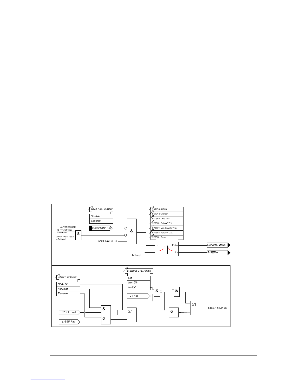
3.4.3 Time Delayed Sensitive Earth Fault Protection (51SEF)
Four elements are provided e.g. giving the option of using two elements set to forward and two to
reverse.
51SEF-n Setting sets the pick-up current level.
A number of shaped characteristics are provided. An inverse definite minimum time (IDMT)
characteristic is selected from IEC and ANSI curves using 51SEF-n Char. A time multiplier is applied
to the characteristic curves using the 51SEF-n Time Mult setting. Alternatively, a definite time lag
(DTL) can be chosen using 51SEF-n Char. When DTL is selected the time multiplier is not applied
and the 51SEF-n Delay (DTL) setting is used instead.
The 51SEF-n Reset setting can apply a definite time delayed reset, or when configured as an ANSI
characteristic an ANSI (DECAYING) reset. If ANSI (DECAYING) reset is selected for an IEC
characteristic, the reset will be instantaneous. The reset mode is significant where the characteristic
has reset before issuing a trip output – see ‘Applications Guide’.
A minimum operate time for the characteristic can be set using 51SEF-n Min. Operate Time setting.
A fixed additional operate time can be added to the characteristic using 51SEF-n Follower DTL
setting.
For the directional elements the direction of operation can be set using 51SEF-n Dir. Control setting.
Directional logic is provided independently for each 51SEF-n element.
Operation of the time delayed earth fault elements can be inhibited from:
Inhibit 51SEF-n A binary or virtual input, or function key
79 SEF Inst Trips: 51SEF-n When ‘delayed’ trips only are allowed in the auto-reclose
sequence (79 SEF Prot’n Trip n = Delayed).
51SEF-n VTSAction: Inhibit Operation of the VT Supervision function.
If the I
4
input is used for SEF, REF cannot be used.
Figure 3.4-3 Logic Diagram: SEF Time Delayed Element (51SEF)
Page 30
(1) Description of Operation 7SR224
Page 30 of 66 ©2009 Siemens Protection Devices Limited
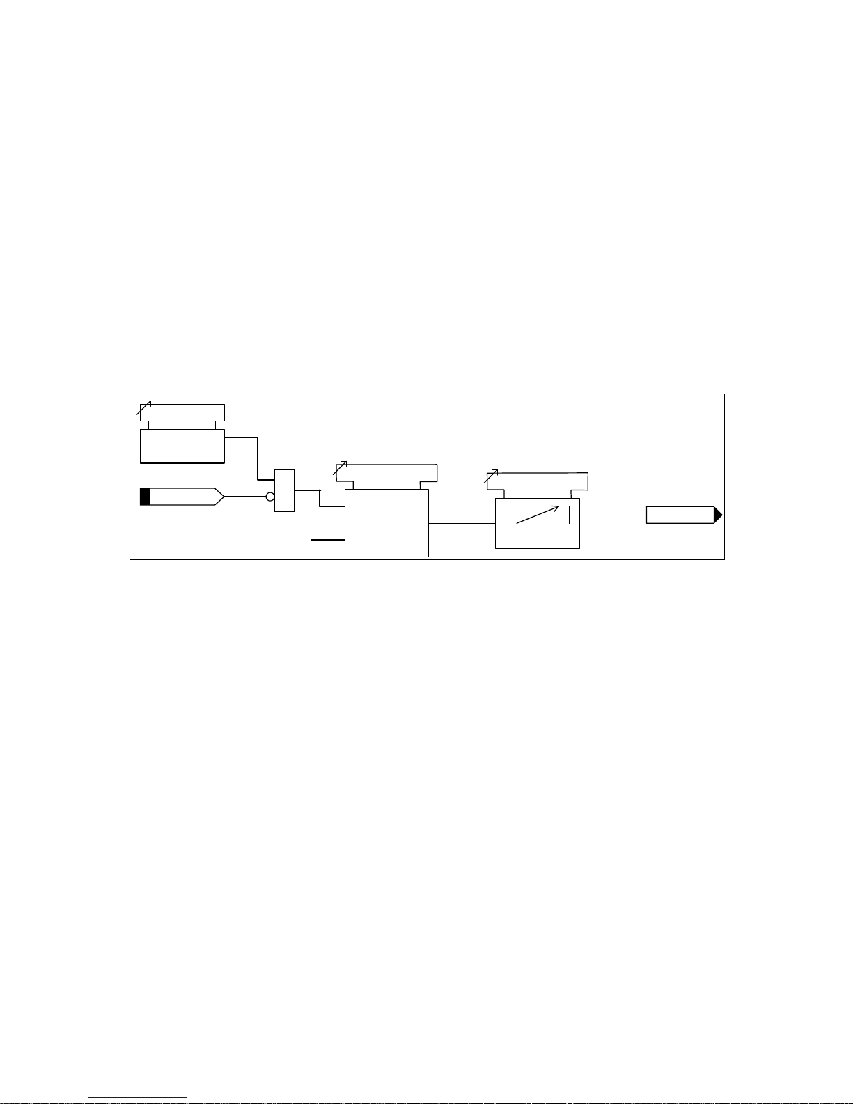
3.5 CURRENT PROTECTION: HIGH IMPEDANCE RESTRICTED EARTH FAULT (64H)
One high impedance Restricted Earth Fault (REF) element is provided.
The relay utilises fundamental current measurement values for this function.
The single phase current input is derived from the residual output of line/neutral CTs connected in
parallel. An external stabilising resistor must be connected in series with this input to ensure that this
element provides a high impedance path. If I
4
is utilised for this purpose, SEF protection cannot be
used.
64H Current Setting sets the pick-up current level. An output is given after elapse of the 64H Delay
setting.
External components – a series stabilising resistor and a non-linear resistor – are used with this
function. See ‘Applications Guide’ for advice in specifying suitable component values.
Operation of the high impedance element can be inhibited from:
Inhibit 64H A binary or virtual input.
64H
>
c
64H Current Setting
64H Delay
c
Inhibit 64H
64H Element
Enabled
Disabled
&
I4(IG)
Figure 3.5-1 Logic Diagram: High Impedance REF (64H)
Page 31
(1) Description of Operation 7SR224
©2009 Siemens Protection Devices Limited Page 31 of 66
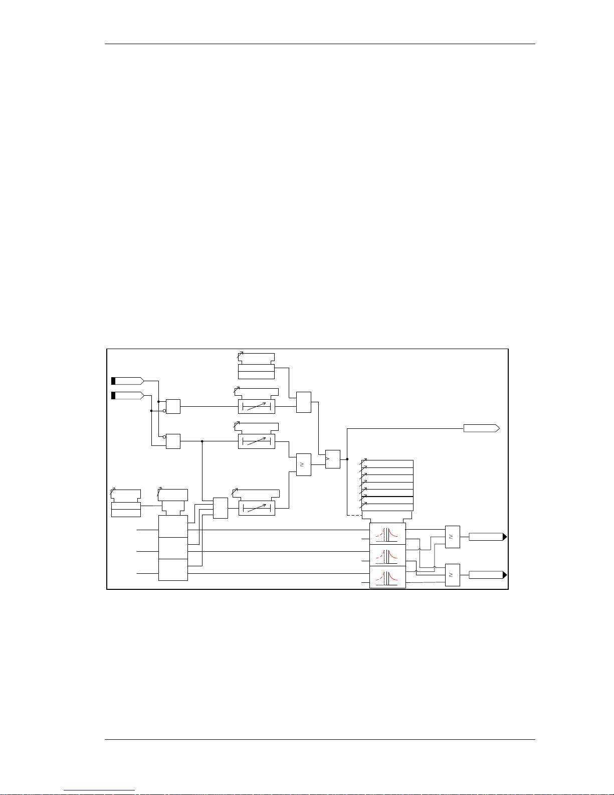
3.6 CURRENT PROTECTION: COLD LOAD (51C)
The setting of each shaped overcurrent element (51-n) can be inhibited and alternative ‘cold load’
settings (51c-n) can be applied for a period following circuit switch in.
The Cold Load settings are applied after the circuit breaker has been open for longer than the Pick-Up
Time setting.
Following circuit breaker closure the ‘cold load’ overcurrent settings will revert to those defined in the
Phase Overcurrent menu (51-n) after either elapse of the Drop-Off Time setting or when the
measured current falls below the Reduced Current Level setting for a time in excess of Reduced
Current Time setting.
During cold load settings conditions any directional settings applied in the Phase Overcurrent menu
are still applicable.
A CB ‘Don’t Believe It’ (DBI) condition is not acted on, causing the element to remain operating in
accordance with the relevant 51-n settings. Where the Reduced Current setting is set to OFF
reversion to 51-n settings will only occur at the end of the Drop-Off Time. If any element is picked up
on expiry of Drop-Off Time the relay will issue a trip and lockout.
If the circuit breaker is re-opened before expiry of the Drop-Off Time the drop-off timer is held but not
reset. Resetting the timer for each trip could result in damaging levels of current flowing for a
prolonged period during a rapid sequence of trips/closes.
Cold load trips use the same binary output(s) as the associated 51-n element.
1
1
General Pickup
51-n
51c-n Setting
51c-n Charact
51c-n Time Mult
51c-n Follower DTL
c
51c-n Reset
Cold Load
Enabled
L1 Dir En
L2 Dir En
L3 Dir En
Disabled
51c-n Min. Operate Time
Reduced
Current
Enabled
Disabled
51c-n Delay (DTL)
CB Open
CB Closed
Pick-up Time
Drop-off Time
Reduced Current DTL
Reduced
Current Level
c
<
IL1
IL2
IL3
51c
See Delayed
Overcurrent
(51-n)
1
&
S
R
Q
&
&
&
CB
Open
CB
Closed
c
Pickup
trip
c
Pickup
trip
c
Pickup
trip
<
<
Figure 3.6-1 Logic Diagram: Cold Load Settings (51c)
Page 32
(1) Description of Operation 7SR224
Page 32 of 66 ©2009 Siemens Protection Devices Limited
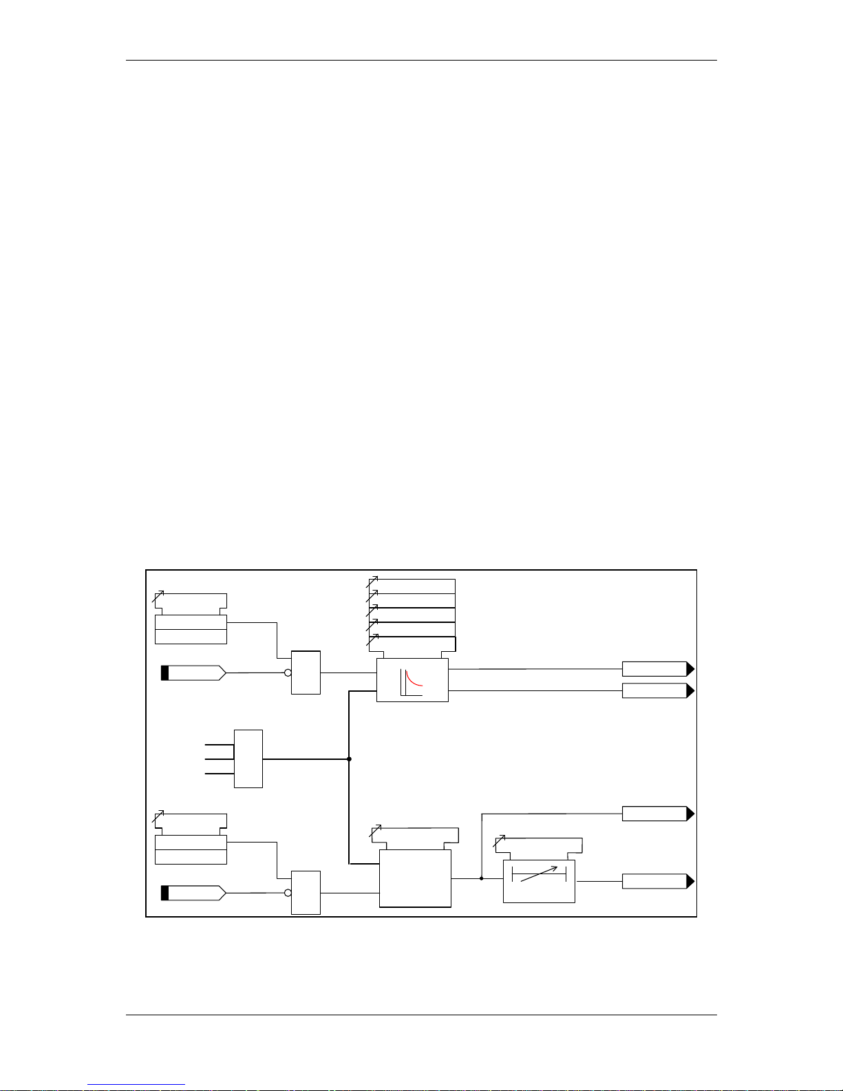
3.7 CURRENT PROTECTION: NEGATIVE PHASE SEQUENCE OVERCURRENT (46NPS)
The negative sequence phase (NPS) component of current (I2) is derived from the three phase
currents. It is a measure of the quantity of unbalanced current in the system.
Two NPS current elements are provided – 46IT and 46DT.
The 46IT element can be configured to be either definite time lag (DTL) or inverse definite minimum
time (IDMT),
46IT Setting sets the pick-up current level for the element.
A number of shaped characteristics are provided. An inverse definite minimum time (IDMT)
characteristic is selected from IEC and ANSI curves using 46IT Char. A time multiplier is applied to the
characteristic curves using the 46IT Time Mult setting. Alternatively, a definite time lag delay (DTL)
can be chosen using 46ITChar. When Delay (DTL) is selected the time multiplier is not applied and
the 46IT Delay (DTL) setting is used instead.
The 46IT Reset setting can apply a, definite time delayed or ANSI (DECAYING) reset.
The 46DT element has a DTL characteristic. 46DT Setting sets the pick-up current and 46DT Delay
the follower time delay.
Operation of the negative phase sequence overcurrent elements can be inhibited from:
Inhibit 46IT A binary or virtual input.
Inhibit 46DT A binary or virtual input.
Inhibit 46IT
46IT
46IT Setting
46IT Char
46IT Time Mult
46IT Delay (DTL)
46IT Element
Enabled
Disabled
&
46IT Reset
IL1
IL2
IL3
NPS
46DT
>
c
46DT Setting
46DT Delay
c
Inhibit 46DT
46DT Element
Enabled
Disabled
&
I2
General Pickup
General Pickup
c
Pickup
trip
Figure 3.7-1 Logic Diagram: Negative Phase Sequence Overcurrent (46NPS)
Page 33
(1) Description of Operation 7SR224
©2009 Siemens Protection Devices Limited Page 33 of 66
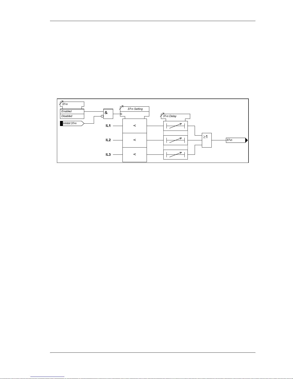
3.8 CURRENT PROTECTION: UNDER-CURRENT (37)
Two under-current elements are provided.
Each phase has an independent level detector and current-timing element. 37-n Setting sets the pickup current. An output is given after elapse of the 37-n Delay setting.
Operation of the under-current elements can be inhibited from:
Inhibit 37-n A binary or virtual input.
Figure 3.8-1 Logic Diagram: Undercurrent Detector (37 )
Page 34

(1) Description of Operation 7SR224
Page 34 of 66 ©2009 Siemens Protection Devices Limited
3.9 CURRENT PROTECTION: THERMAL OVERLOAD (49)
The relay provides a thermal overload suitable for the protection of static plant. Phase segregated
elements are provided. The temperature of the protected equipment is not measured directly. Instead,
thermal overload conditions are calculated using the measure True RMS current.
Should the current rise above the 49 Overload Setting for a defined time an output signal will be
initiated.
Operate Time (t):-
()
⎭
⎬
⎫
⎩
⎨
⎧
×−
−
×=
2
B
2
2
P
2
IkI
II
t ln
τ
Where
T = Time in minutes
τ = 49 Time Constant setting (minutes)
In = Log Natural
I = measured current
I
P
= Previous steady state current level
k = Constant
I
B
= Basic current, typically the same as In
k.I
B
= 49 Overload Setting (I
θ
)
Additionally, an alarm can be given if the thermal state of the system exceeds a specified percentage
of the protected equipment’s thermal capacity 49 Capacity Alarm setting.
For the heating curve:
100%)e(1
I
I
θ
τ
t
2
θ
2
×−⋅=
−
Where: θ = thermal state at time t
I = measured thermal current
I
θ
= 49 Overload setting (or k.I
B
)
The final steady state thermal condition can be predicted for any steady state value of input current
where t >τ,
100%
I
I
θ
2
θ
2
F
×=
Where: θ
F
= final thermal state before disconnection of device
49 Overload Setting I
θ
is expressed as a multiple of the relay nominal current and is equivalent to the
factor k.I
B
as defined in the IEC255-8 thermal operating characteristics. It is the value of current above
Page 35
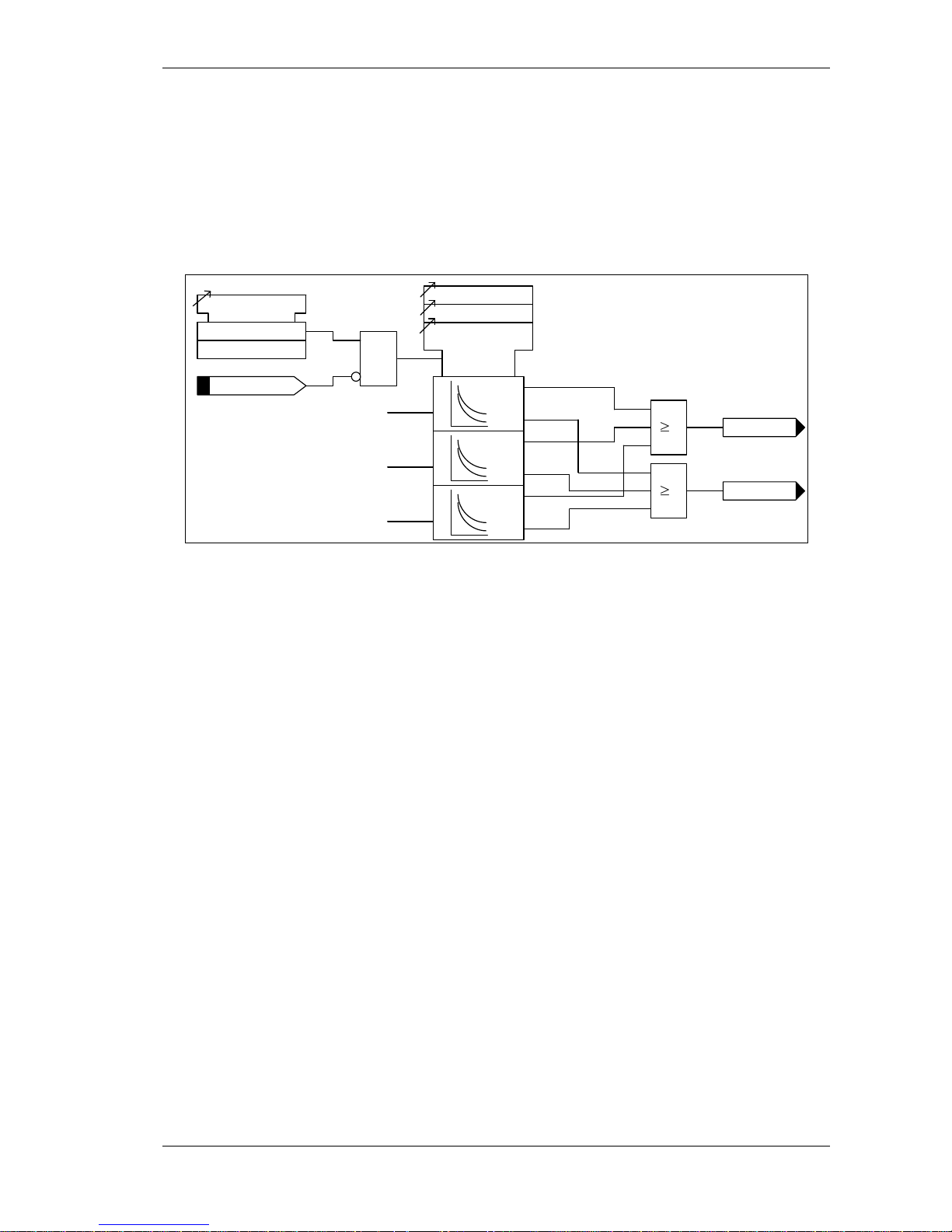
(1) Description of Operation 7SR224
©2009 Siemens Protection Devices Limited Page 35 of 66
which 100% of thermal capacity will be reached after a period of time and it is therefore normally set
slightly above the full load current of the protected device.
The thermal state may be reset from the fascia or externally via a binary input.
Thermal overload protection can be inhibited from:
Inhibit 49 A binary or virtual input.
IL1
49 Alarm
49 Trip
49 Time Constant
49 Capacity Alarm
49 Overload Setting
c
cap alarm
trip
IL2
IL3
cap alarm
trip
cap alarm
trip
Inhibit 49
49 Therm. Overload
Enabled
Disabled
&
1
1
Figure 3.9-1 Logic Diagram: Thermal Overload Protection (49S)
Page 36
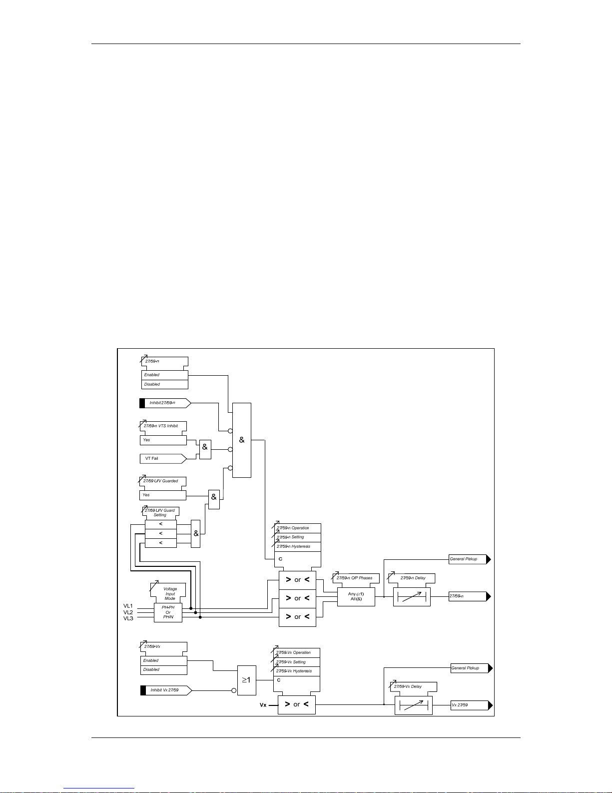
(1) Description of Operation 7SR224
Page 36 of 66 ©2009 Siemens Protection Devices Limited
3.10 VOLTAGE PROTECTION: PHASE UNDER/OVER VOLTAGE (27/59)
In total five under/over voltage elements are provided. Four elements are provided for the ‘Phase’
Voltages and one for the ‘Auxiliary’ input voltage.
The relay utilises fundamental frequency RMS voltage for this function. All under/over voltage
elements have a common setting to measure phase to phase (Ph-Ph) or phase to neutral (Ph-N)
voltage using the Voltage Input Mode setting.
Voltage elements can be blocked if all phase voltages fall below the 27/59 U/V Guard setting.
27/59-n (27/59-Vx) Setting sets the pick-up voltage level for the element.
The sense of the element (undervoltage or overvoltage) is set by the 27/59-n Operation (27/59-Vx
Operation) setting.
The 27/59-n O/P Phases setting determines whether the time delay is initiated for operation of any
phase or only when all phases have detected the appropriate voltage condition. An output is given
after elapse of the 27/59-n Delay (27/59-Vx Delay) setting.
The 27/59-n Hysteresis (27/59-Vx Hysteresis) setting allows the user to vary the pick-up/drop-off
ratio for the element.
Operation of the under/over voltage elements can be inhibited from:
Inhibit 27/59-n A binary or virtual input.
27/59-n VTSInhibit: Yes Operation of the VT Supervision function.
27/59-n U/V Guarded Under voltage guard element.
Figure 3.10-1 Logic Diagram: Under/Over Voltage Elements (27/59)
Page 37
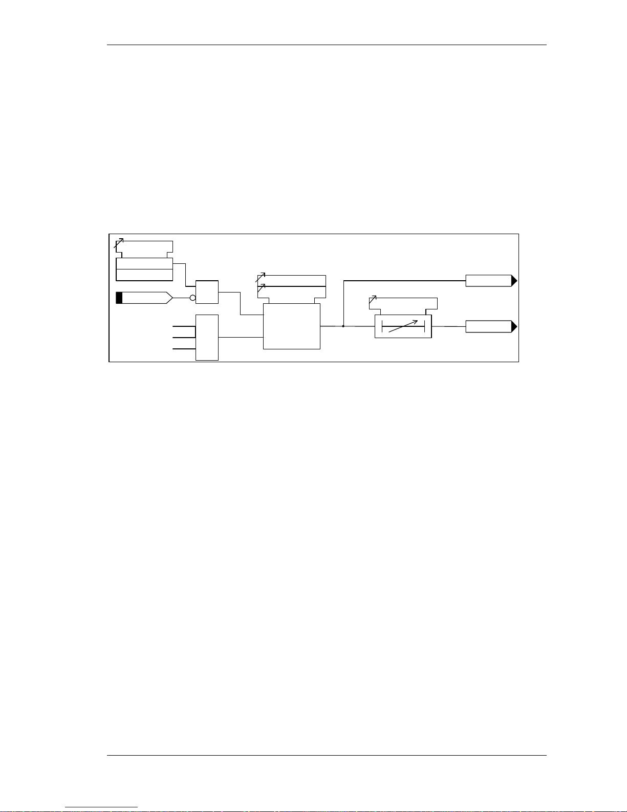
(1) Description of Operation 7SR224
©2009 Siemens Protection Devices Limited Page 37 of 66
3.11 VOLTAGE PROTECTION: NEGATIVE PHASE SEQUENCE OVERVOLTAGE (47)
Negative phase sequence (NPS) voltage (V2) is a measure of the quantity of unbalanced voltage in
the system. The relay derives the NPS voltage from the three input voltages (VL1, VL2 and VL3).
Two elements are provided.
47-n Setting sets the pick-up voltage level for the element.
The 47-n Hysteresis setting allows the user to vary the pick-up/drop-off ratio for the element.
An output is given after elapse of the 47-n Delay setting.
Operation of the negative phase sequence voltage elements can be inhibited from:
Inhibit 47-n A binary or virtual input.
Inhibit 47-n
47-n Element
Enabled
Disabled
47-n
47-n Delay
&
c
47-n Hysteresis
>
47-n Setting
VL1
VL2
VL3
NPS
Filter
V2
General Pickup
Figure 3.11-1 Logic Diagram: NPS Overvoltage Protection (47)
Page 38

(1) Description of Operation 7SR224
Page 38 of 66 ©2009 Siemens Protection Devices Limited
3.12 VOLTAGE PROTECTION: NEUTRAL OVERVOLTAGE (59N)
Two Neutral Overvoltage (or Neutral Voltage Displacement) elements are provided.
59N Voltage Source setting selects the source of the residual voltage to be measured. The voltage is
measured directly from the Vx input or derived from the line voltages where suitable VT connections
are present. The relay utilises fundamental voltage measurement values for this function.
One of the elements can be configured to be either definite time lag (DTL) or inverse definite minimum
time (IDMT),
59NIT Setting sets the pick-up voltage level (3V
0
) for the element.
An inverse definite minimum time (IDMT) can be selected using 59NIT Char. A time multiplier is
applied to the characteristic curves using the 59NIT Time Mult setting (M):
Alternatively, a definite time lag delay (DTL) can be chosen using 59NITChar. When Delay (DTL) is
selected the time multiplier is not applied and the 59NIT Delay (DTL) setting is used instead.
An instantaneous or definite time delayed reset can be applied using the 59NIT Reset setting.
The second element has a DTL characteristic. 59NDT Setting sets the pick-up voltage (3V
0
) and
59NDT Delay the follower time delay.
Operation of the neutral overvoltage elements can be inhibited from:
Inhibit 59NIT A binary or virtual input.
Inhibit59NDT A binary or virtual input.
It should be noted that neutral voltage displacement can only be applied to VT arrangements that
allow zero sequence flux to flow in the core i.e. a 5-limb VT or 3 single phase VTs. The VT primary
winding neutral must be earthed to allow the flow of zero sequence current.
Figure 3.12-1 Logic Diagram: Neutral Overvoltage Element
[]
s
⎥
⎥
⎦
⎤
⎢
⎢
⎣
⎡
−=1
M
t
Vs
3Vo
op
Page 39
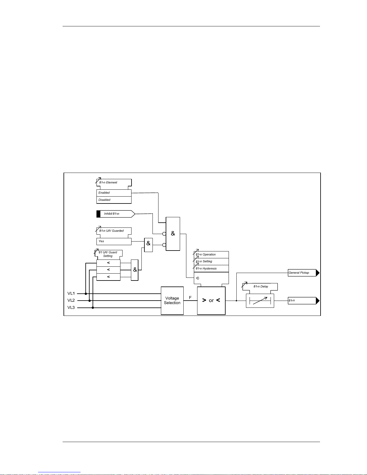
(1) Description of Operation 7SR224
©2009 Siemens Protection Devices Limited Page 39 of 66
3.13 VOLTAGE PROTECTION: UNDER/OVER FREQUENCY (81)
Four under/over frequency elements are provided.
The relay utilises fundamental voltage measurement values for this function. The frequency
calculation is based on the highest input voltage derived from the voltage selection algorithm.
Frequency elements are blocked if all phase voltages fall below the 81 U/V Guard setting.
The sense of the element (under-frequency or over-frequency) is set by the 81-n Operation setting.
81-n Setting sets the pick-up voltage level for the element.
An output is given after elapse of the 81-n Delay setting.
The 81-n Hysteresis setting allows the user to vary the pick-up/drop-off ratio for the element.
Operation of the under/over voltage elements can be inhibited from:
Inhibit 81-n A binary or virtual input.
81-n U/V Guarded Under voltage guard element.
Figure 3.13-1 Logic Diagram: Under/ O ver Frequency Detector (81)
Page 40

(1) Description of Operation 7SR224
Page 40 of 66 ©2009 Siemens Protection Devices Limited
Section 4: Control & Logic Functions
4.1 AUTO-RECLOSE (79)
4.1.1 Overview
A high proportion of faults on an Overhead Line (OHL) network are transient. These faults can be
cleared and the network restored quickly by using Instantaneous (Fast) Protection trips followed by an
automated sequence of CB reclosures after the line has been dead for a short time, this ‘deadtime’
allows the fault current arc to fully extinguish. Typically, this auto reclose (AR) sequence of
Instantaneous Trip(s) and Reclose Delays (Dead times) followed by Delayed Trip(s) provides the
automatic optimum method of clearing all types of fault i.e. both Transient and Permanent, as quickly
as possible and achieving the desired outcome of keeping as much of the Network in-service as
possible.
The AR function, therefore, has to: -
Control the type of Protection trip applied at each stage of a sequence
Control the Auto Reclose of the Circuit Breaker to provide the necessary network Dead times,
to allow time for Arc extinction
Co-ordinate its Protection and Auto Reclose sequence with other fault clearing devices.
A typical sequence would be – 2 Instantaneous+1Delayed+HighSet Trips with 1 sec & 10 sec dead
times.
The Autoreclose feature may be switched in and out of service by a number of methods, these are:
79 Autoreclose ENABLE/DISABLE (AUTORECLOSE CONFIG menu)
A keypad change from the CONTROL MODE
Customer programmed function key (using Quick Logic)
Via the data communications channel(s),
From a 79 OUT binary input. Note the 79 OUT binary input has priority over the 79 IN binary
input - if both are raised the auto-reclose will be Out of Service.
Knowledge of the CB position status is integral to the auto-reclose functionality. CB auxiliary switches
must be connected to CB Closed and CB Open binary inputs. A circuit breaker’s service status is
determined by its position i.e. from the binary inputs programmed CB Open and CB Closed. The
circuit breaker is defined as being in service when it is closed. The in service status has a drop-off
delay of 2 sec, this delay is known as the circuit memory time. This functionality prevents
autoreclosing when the line is normally de-energised, or normally open.
Auto-Reclose (AR) is started by a valid trip relay operation while the associated circuit breaker is in
service.
The transition from AR started to deadtime initiation takes place when the CB has opened and the
protection pickups have reset and the trip relay has reset. If any of these do not occur within the 79
Sequence Fail Timer setting the relay will Lockout. This prevents the AR being primed indefinitely.
79 Sequence Fail Timer can be switched to 0 (= OFF).
Once a AR sequence has been initiated, up to 4 reclose operations can be attempted before the AR
feature is locked-out. Number of recloses is determined by 79 Num Shots. Each reclosure (shot) is
preceded by a time delay - 79 Elem Deadtime n - giving transient faults time to clear. Separate dead-
time settings are provided for each of the 4 recloses and for each of the four fault types – P/F, E/F,
SEF and External.
Once a CB has reclosed and remained closed for a specified time period (the Reclaim time), the AR
sequence is re-initialised and a Successful Close output issued. A single, common Reclaim time is
used (Reclaim Timer).
Page 41

(1) Description of Operation 7SR224
©2009 Siemens Protection Devices Limited Page 41 of 66
When an auto-reclose sequence does not result in a successful reclosure the relay goes to the lockout
state.
Indications
The Instruments Menu includes the following meters relevant to the status of the Auto-Reclose and
Manual Closing of the circuit breaker: -
Status of the AR sequence
AR Shot Count.
CB Open Countdown Timer
CB Close Countdown Timer
Inputs
External inputs to the recloser functionality are wired to the binary inputs. Functions which can be
mapped to these binary inputs include: -
79 Out (edge triggered)
79 In (edge triggered)
CB Closed
CB Open
79 Ext Trip
79 Ext Pickup
79 Block Reclose
Block Close CB
Close CB
79 Trip & Reclose
79 Trip & Lockout
79 Line Check
Hot Line In
Hot Line Out
Outputs
Outputs are fully programmable to either binary outputs or LEDs. Programmable outputs include: -
79 Out Of Service
79 In Service
79 In Progress
Sequence Fail
CB Close
79 Successful AR
79 Lockout
79 CloseOnFault
79 CB Close Fail
Page 42
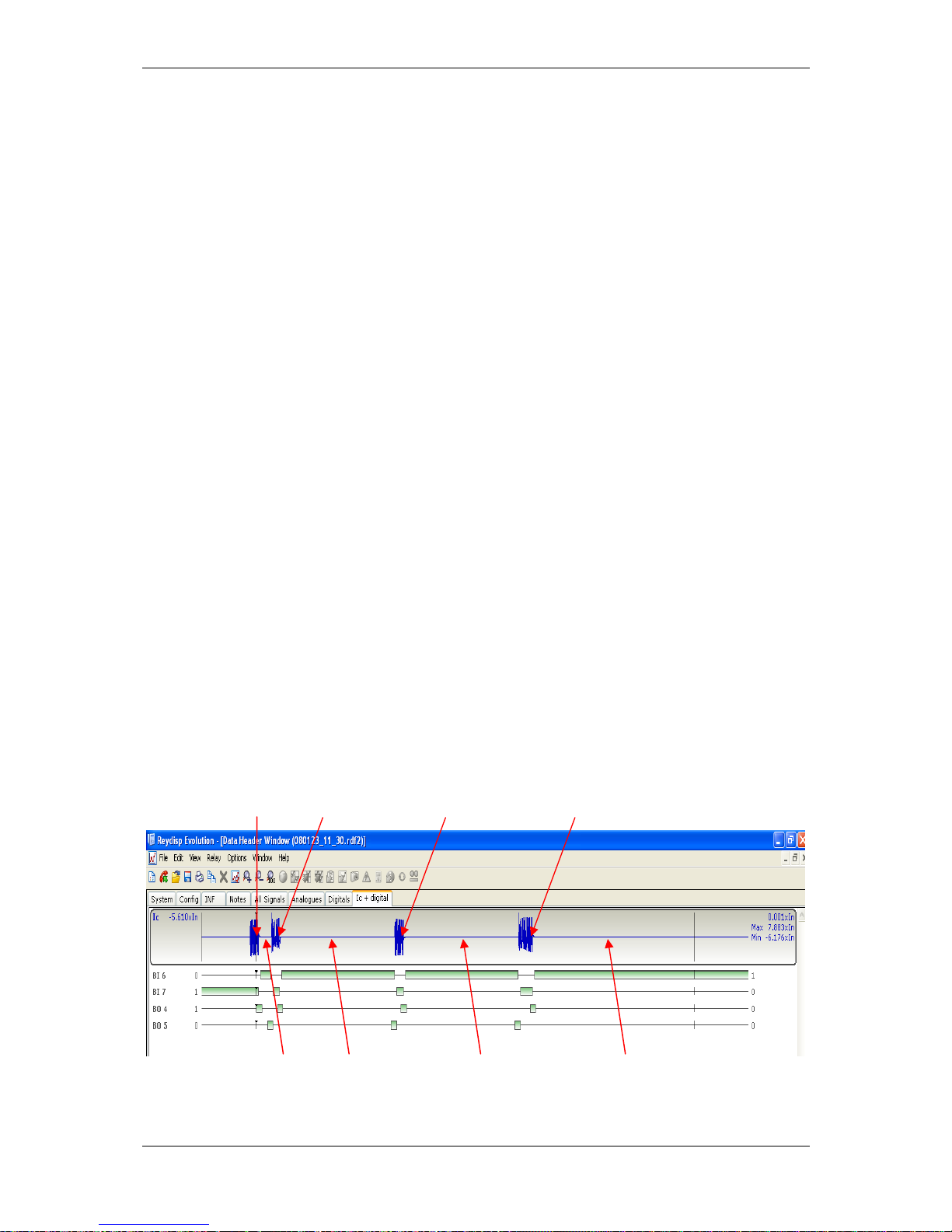
(1) Description of Operation 7SR224
Page 42 of 66 ©2009 Siemens Protection Devices Limited
1
s
t
Trip (Inst) 2
n
d
Trip (Inst)
3
r
d
Trip (Inst)
4th Trip (Delayed)
4th Dead Time
3
r
d
Dead Time
2
n
d
Dead Time
1
s
t
Dead Time
Auto Reclose sequences
The CONTROL & LOGIC>AUTO RECLOSE PROT’N and CONTROL & LOGIC>AUTORECLOSE
CONFIG’ menus, allow the user to set independent Protection and Auto Reclose sequences for each
type of fault i.e. Phase Fault (P/F), Earth Fault (E/F), Sensitive Earth Fault (SEF) or External
Protections (EXTERN). Each Auto Reclose sequence can be user set for up to four-shots i.e. five trips
+ four reclose sequence, with independently configurable type of Protection Trip, either Fast (Inst) or
Delayed with associated Deadtime Delay time for each shot. The user has programming options for
Auto Reclose Sequences up to the maximum shot count i.e.:-
Inst or Delayed Trip 1 + (DeadTime 1: 0.1s-14400s)
+ Inst or Delayed Trip 2 + (DeadTime 2: 0.1s-14400s)
+ Inst or Delayed Trip 3 + (DeadTime 3: 0.1s-14400s)
+ Inst or Delayed Trip 4 + (DeadTime 4: 0.1s-14400s)
+ Inst or Delayed Trip 5 – Lockout.
The AR function recognizes developing faults and, as the shot count advances, automatically applies
the correct type of Protection Trip and associated Dead time for that fault-type at that point in the
sequence.
A typical sequence would consist of two Inst trips followed by at least one combined Delayed +
HighSet (HS) Trip. This sequence enables transient faults to be cleared quickly by the Inst trip(s) and
permanent fault to be cleared by the combined Delayed trip. The delayed trip must be ‘graded’ with
other Recloser/CB’s to ensure system discrimination is maintained, i.e. that as much of the system as
possible is live after the fault is cleared.
A HS trips to lockout setting is provided such that when the number of operations of elements
assigned as HS trips reach the setting the relay will go to lockout.
The number of Shots (Closes) is user programmable, note: - only one Shot Counter is used to
advance the sequence, the Controller selects the next Protection characteristic/Dead time according
to the type of the last Trip in the sequence e.g. PF, EF, SEF or EXTERNAL.
Reclose Dead Time
User programmable dead times are available for each protection trip operation.
The dead time is initiated when the trip output contact reset, the pickup is reset and the CB is open.
The CB close output relay is energised after the dead time has elapsed.
Figure 4.1-1 Typical Auto Reclose Sequence with 3 Instantaneous and 1 Delayed trip
Page 43

(1) Description of Operation 7SR224
©2009 Siemens Protection Devices Limited Page 43 of 66
4.1.2 AUTORECLOSE PROT’N Menu
This menu presents the Overcurrent Protection elements available for each type of Fault i.e. P/F, E/F
or SEF and allows the user to select those that are to be applied as Inst trips; those that are to be
applied as Delayed Trips; and those that are to be applied as HS Trips (HighSet), as required by the
selected sequence. There is no corresponding setting for External as the External protection type is
not normally controlled by the Auto Reclose Relay. The resultant configuration enables the Auto
Reclose function to correctly apply the required Protection for each shot in a sequence.
4.1.3 AUTORECLOSE CONFIG Menu
This menu allows the following settings to be made:-
79 Autoreclose Enabled turns ON all AutoReclose Functions.
79 Num Shots Sets the allowed number of AutoReclose attempts in a sequence.
79 Retry Enable Enabled configures the relay to perform further attempts to automatically
Close the Circuit Breaker where the CB has initially failed to close in response
to a Close command. If the first attempt fails the relay will wait for the 79
Retry Interval to expire then attempt to Close the CB again.
79 Retry Attempts Sets the maximum number of retry attempts.
79 Retry Interval Sets the time delay between retry attempts.
79 Reclose Blocked Delay If the CB is not ready to receive a Close command or if system
conditions are such that the CB should not be closed immediately e.g. a
close-spring is not charged, then a Binary input mapped to Reclose Block
can be raised and the Close pulse will not be issued but will be held-back.
The 79 Reclose Blocked Delay sets the time Reclose Block is allowed to
be raised, if this time delay expires the Relay will go to Lockout. If Reclose
Block is cleared, before this time expires, then the CB Close pulse will be
issued at that point in time. Dead Time + Reclose Blocked Delay = Lockout.
79 Sequence Fail Timer Sets the time that AR start can be primed. Where this time expires before all
the AR start signals are not received i.e. the CB has opened, protection
pickups have reset and the trip relay has reset, the Relay goes to Lockout.
79 Minimum Lockout Delay Sets the time that the Relay’s Lockout condition is maintained. After the
last allowed Trip operation in a specific sequence the Circuit Breaker will be
left locked-out in the open position and can only be closed by manual or
remote SCADA operation. The 79 Minimum Lockout Delay timer can be set
to delay a too-fast manual close after lockout, this prevents an operator from
manually closing onto the same fault too quickly and thus performing multiple
sequences and possibly burning-out Plant.
79 Reset LO by Timer Set to Enabled this ensures that the Lockout condition is reset when the timer
expires, Lockout indication will be cleared; otherwise, set to Disabled, the
Lockout condition will be maintained until the CB is Closed by a Close
command.
79 Sequence Co-Ord When set to Enabled the Relay will co-ordinate its sequence and shot count
such that it automatically keeps in step with downstream devices as they
advance through their sequence. The Relay detects that a pickup has
operated but has dropped-off before its associated time delay has expired, it
then increments its Shot count and advances to the next stage of the auto-
reclose sequence without issuing a trip, this is repeated as long as the fault is
being cleared by the downstream device such that the Relay moves through
the sequence bypassing the INST Trips and moving on to the Delayed Trip to
maintain Grading margins.
Page 44

(1) Description of Operation 7SR224
Page 44 of 66 ©2009 Siemens Protection Devices Limited
Notes on the ‘Lockout’ State
The Lockout state can be reached for a number of reasons. Lockout will occur for the following: -
• At the end of the 79 Sequence Fail Timer.
• At the end of the Reclaim timer if the CB is in the open position.
• A protection operates during the final Reclaim time.
• If a Close Pulse is given and the CB fails to close.
• The 79 Lockout binary input is active.
• At the end of the 79 Reclose Blocked Delay due to presence of a persistent Block signal.
• When the 79 Elem HS Trips to Lockout count is reached.
• When the 79 Elem Delayed Trips to Lockout count is reached.
Once lockout has occurred, an alarm (79 Lockout) is issued and all further Close commands, except
manual close, are inhibited.
If the Lockout command is received while a Manual Close operation is in progress, the feature is
immediately locked-out.
Once the Lockout condition has been reached, it will be maintained until reset. The following will reset
lockout: -
• By a Manual Close command, from fascia, comms or Close CB binary input.
• By a 79 Reset Lockout binary input, provided there is no signal present that will cause
Lockout.
• At the end of the 79 Minimum LO Delay time setting if 79 Reset LO by Timer is selected
to ENABLED, provided there is no signal present which will cause Lockout.
• Where Lockout was entered by an A/R Out signal during an Autoreclose sequence then a
79 In signal must be received before Lockout can reset.
• By the CB Closed binary input, provided there is no signal present which will cause
Lockout.
The Lockout condition has a delayed drop-off of 2s.
Page 45

(1) Description of Operation 7SR224
©2009 Siemens Protection Devices Limited Page 45 of 66
4.1.4 P/F SHOTS sub-menu
This menu allows the Phase fault trip/reclose sequence to be parameterized:-
79 P/F Prot’n Trip1 The first protection Trip in the P/F sequence can be set to either Inst or
Delayed.
79 P/F Deadtime 1 Sets the first Reclose Delay (Dead time) in the P/F sequence.
79 P/F Prot’n Trip2 The second protection Trip in the P/F sequence can be set to either Inst or
Delayed.
79 P/F Deadtime 2 Sets the second Reclose Delay (Dead time) in the P/F sequence.
79 P/F Prot’n Trip3 The third protection Trip in the P/F sequence can be set to either Inst or
Delayed.
79 P/F Deadtime 3 Sets the third Reclose Delay (Dead time) in the P/F sequence.
79 P/F Prot’n Trip 4 The fourth protection Trip in the P/F sequence can be set to either Inst or
Delayed.
79 P/F Deadtime 4 Sets the fourth Reclose Delay (Dead time) in the P/F sequence.
79 P/F Prot’n Trip5 The fifth and last protection Trip in the P/F sequence can be set to either Inst
or Delayed.
79 P/F HighSet Trips to Lockout Sets the number of allowed HighSet trips. The relay will go to
Lockout on the last HighSet Trip. This function can be used to limit the
duration and number of high current trips that the Circuit Breaker is required
to perform, if the fault is permanent and close to the Circuit Breaker then there
is no point in forcing a number of Delayed Trips before the Relay goes to
Lockout – that sequence will be truncated.
79 P/F Delayed Trips to Lockout Sets the number of allowed Delayed trips, Relay will go to Lockout
on the last Delayed Trip. This function limits the number of Delayed trips that
the Relay can perform when the Instantaneous protection Elements are
externally inhibited for system operating reasons - sequences are truncated.
4.1.5 E/F SHOTS sub-menu
This menu allows the Earth Fault trip/reclose sequence to be parameterized:-
As above but E/F settings.
4.1.6 SEF SHOTS sub-menu
This menu allows the Sensitive Earth trip/reclose sequence to be parameterized:-
As above but SEF Settings, Note: - SEF does not have HighSets
Page 46

(1) Description of Operation 7SR224
Page 46 of 66 ©2009 Siemens Protection Devices Limited
4.1.7 EXTERN SHOTS sub-menu
This menu allows the External Protection auto-reclose sequence to be parameterized:-
79 P/F Prot’n Trip1 Not Blocked/Blocked - Blocked raises an output which can be mapped to a
Binary output to Block an External Protection’s Trip Output.
79 P/F Deadtime 1 Sets the first Reclose Delay ( Deadtime) for the External sequence.
79 P/F Prot’n Trip2 Not Blocked/Blocked - Blocked raises an output which can be mapped to a
Binary Output to Block an External Protection’s second Trip output.
79 P/F Deadtime 2 Sets the second Reclose Delay ( Deadtime) in the External sequence.
79 P/F Prot’n Trip3 Not Blocked/Blocked - Blocked raises an output which can be mapped to a
Binary output to Block an External Protection’s third Trip Output.
79 P/F Deadtime 3 Sets the third Reclose Delay (Deadtime) in the External sequence.
79 P/F Prot’n Trip4 Not Blocked/Blocked - Blocked raises an output which can be mapped to a
Binary output to Block an External Protection’s fourth Trip Output.
79 P/F Deadtime 4 Sets the fourth Reclose Delay (Deadtime) in the External sequence.
79 P/F Prot’n Trip5 Not Blocked/Blocked - Blocked raises an output which can be mapped to a
Binary output to Block an External Protection’s fifth Trip Output.
79 P/F Extern Trips to Lockout - Sets the number of allowed External protection’ trips, Relay will go
to Lockout on the last Trip.
These settings allow the user to set-up a separate AutoReclose sequence for external protection(s)
having a different sequence to P/F, E/F or SEF protections. The ‘ Blocked ‘ setting allows the
Autoreclose sequence to raise an output at any point in the sequence to Block further Trips by the
External Protection thus allowing the Overcurrent P/F or Earth Fault or SEF elements to apply
Overcurrent Grading to clear the fault.
Other Protection Elements in the Relay can also be the cause of trips and it may be that AutoReclose
is required; the External AutoReclose sequence can be applied for this purpose. By setting-up internal
Quick Logic equation(s) the user can define and set what should occur when any one of these other
elements operates.
Note: If the ‘CB Total Trip Count’ or the ‘CB Frequent Ops Count’ target is reached the relay will do
one delayed tip and lockout*.
*NB: If Delayed Trips are not assigned in the AUTORECLOSE PROT’N menu the relay will not trip.
Page 47
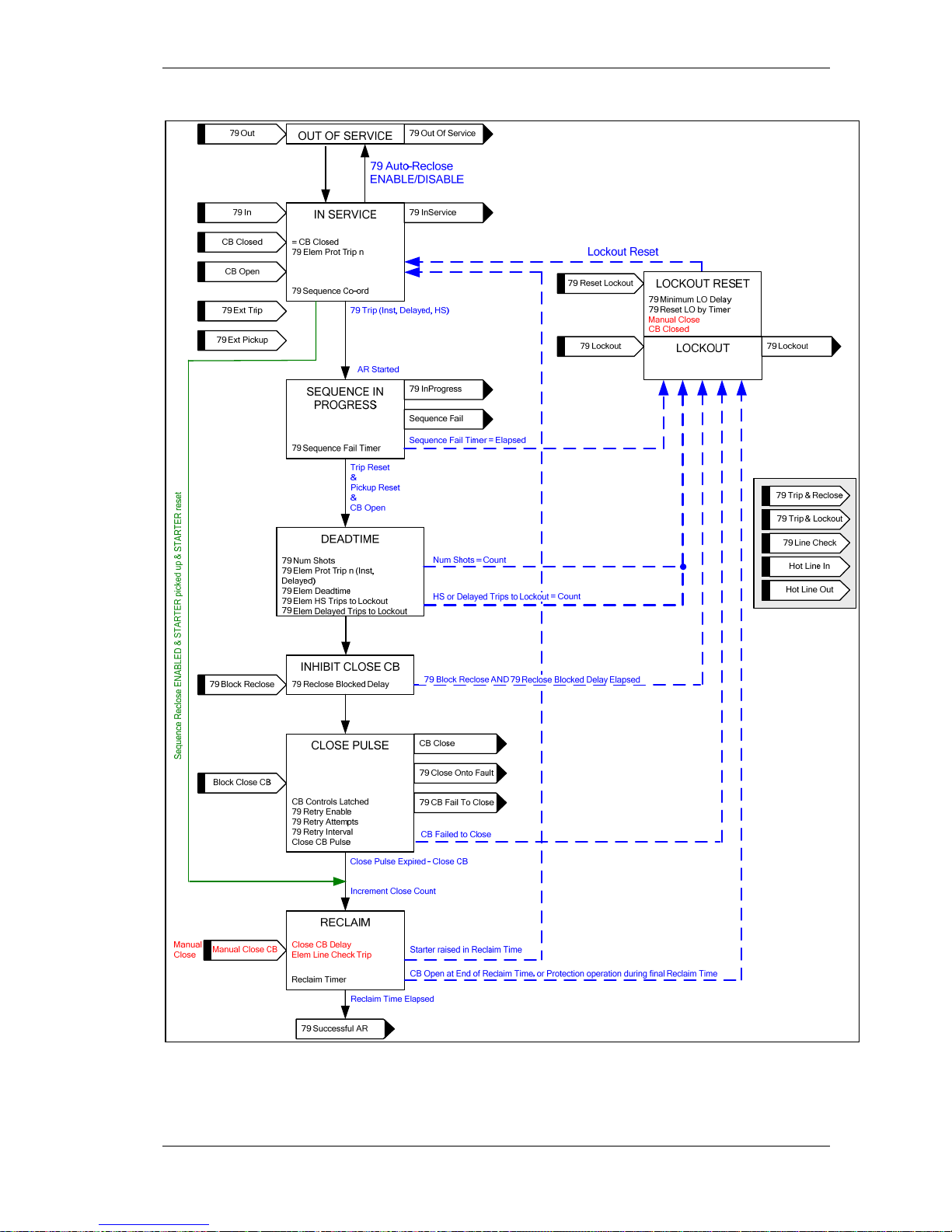
(1) Description of Operation 7SR224
©2009 Siemens Protection Devices Limited Page 47 of 66
Figure 4.1-2 Basic Auto-Reclose Sequence Diagram
Page 48

(1) Description of Operation 7SR224
Page 48 of 66 ©2009 Siemens Protection Devices Limited
4.2 MANUAL CLOSE
A Manual Close Command can be initiated in one of three ways: via a Close CB binary input, via the
data communication Channel(s) or from the relay CONTROL MODE menu. It causes an instantaneous
operation via 79MC Close CB binary output, over-riding any auto-reclose (AR) sequence in progress.
Repeated Manual Closes are avoided by checking for Positive edge triggers. Even if the Manual Close
input is constantly energised the relay will only attempt one close.
A Manual Close will initiate Line Check if enabled. If a fault appears on the line during the Close
Pulse or during the Reclaim Time with Line Check enabled, the relay will initiate a Trip and Lockout.
This prevents a CB being repeatedly closed onto a faulted line. Where Line Check = DELAYED then
instantaneous protection is inhibited until the reclaim time has elapsed.
Manual Close resets Lockout, if the conditions that set Lockout have reset i.e. there is no trip or
Lockout input present.
Manual Close cannot proceed if there is a Lockout input present.
With the Autoreclose function set to Disabled the Manual Close control is still active.
4.3 CIRCUIT BREAKER
This menu includes relay settings applicable to both manual close (MC) and auto-reclose (AR)
functionality.
CB Controls Latched
CB controls for closing and tripping can be latched i.e. until confirmation that the action has been
completed i.e. binary input is edge triggered when latched.
Close CB Delay
The Close CB Delay is applicable to manual CB close commands received through a Close CB binary
input or via the Control Menu. Operation of the 79 MC Close CB binary output is delayed by the
Close CB Delay setting.
Close CB Pulse
The duration of the CB Close Pulse is settable to allow a range of CBs to be used. The Close pulse
will be terminated if any protection picks-up operates or a trip occurs. This is to prevent Close and Trip
Command pulses existing simultaneously. A 79 Close On Fault Output is given if a pick-up or trip
operates during the Close Pulse. This can be independently wired to Lockout.
‘CB Failed To Open and CB Failed to Close features are used to confirm that a CB has not responded
correctly to each Trip and Close Command. If a CB fails to operate, the AR feature will go to lockout.
’79 CB Close Fail’ is issued if the CB is not closed at the end of the close pulse, CB Close Pulse.
Reclaim Timer
The ‘Reclaim time’ will start each time a Close Pulse has timed out and the CB has closed.
Where a protection pickup is raised during the reclaim time the relay advances to the next part of the
reclose sequence.
The relay goes to the Lockout state if the CB is open at the end of the reclaim time or a protection
operates during the final reclaim time.
Page 49

(1) Description of Operation 7SR224
©2009 Siemens Protection Devices Limited Page 49 of 66
Blocked Close Delay
The close command may be delayed by a Block Close CB signal applied to a binary input. This
causes the feature to pause before it issues the CB close command and can be used, for example, to
delay CB closure until the CB energy has reached an acceptable level. If the Block signal has not
been removed before the end of the defined time, Blocked Close Delay, the relay will go to the
lockout state.
Open CB Delay
The Open CB Delay setting is applicable to CB trip commands received through an Open CB binary
input or via the Control Menu. Operation of the Open CB binary output is delayed by the Open CB
Delay setting.
Open CB Pulse
The duration of the CB open Command pulse is user settable to allow a range of CBs to be used.
CB Failed To Open is taken from the Circuit Breaker Failure Element.
CB Travel Alarm
The CB Open/CB Closed binary inputs are monitored. The relay goes to Lockout and an output can be
given where a 0/0 condition exists for longer than the CB Travel Alarm setting.
An instantaneous output is given for a 1/1 state.
Hot Line In/Out
When ‘Hot Line’ is enabled all auto reclose sequences are inhibited and any fault causes an
instantaneous trip to lockout.
Figure 4.3-1 Logic Diagram: Circuit Breaker Status
Page 50

(1) Description of Operation 7SR224
Page 50 of 66 ©2009 Siemens Protection Devices Limited
4.4 QUICK LOGIC
The ‘Quick Logic’ feature allows the user to input up to 16 logic equations (E1 to E16) in text format.
Equations can be entered using Reydisp or at the relay fascia.
Each logic equation is built up from text representing control characters. Each can be up to 20
characters long. Allowable characters are:
0, 1, 2, 3, 4, 5, 6, 7, 8, 9 Digit
( ) Parenthesis
! ‘NOT’ Function
. ‘AND’ Function
^ ‘EXCLUSIVE OR’ Function
+ ‘OR’ Function
En Equation (number)
Fn Function Key (number)
‘1’ = Key pressed, ‘0’ = Key not pressed
In Binary Input (number)
‘1’ = Input energised, ‘0’ = Input de-energised
Ln LED (number)
‘1’ = LED energised, ‘0’ = LED de-energised
On Binary output (number)
‘1’ = Output energised, ‘0’ = Output de-energised
Vn Virtual Input/Output (number)
‘1’ = Virtual I/O energised, ‘0’ = Virtual I/O de-energised
Example Showing Use of Nomenclature
E1= ((I1^F1).!O2)+L1
Equation 1 = ((Binary Input 1 XOR Function Key 1) AND NOT Binary Output 2)
OR
LED 1
When the equation is satisfied (=1) it is routed through a pick-up timer (En Pickup Delay), a drop-off
timer (En Dropoff Delay), and a counter which instantaneously picks up and increments towards its
target (En Counter Target).
The counter will either maintain its count value En Counter Reset Mode = OFF, or reset after a time
delay:
En Counter Reset Mode = Single Shot: The En Counter Reset Time is started only when
the counter is first incremented (i.e. counter value = 1) and not for subsequent counter
operations. Where En Counter Reset Time elapses and the count value has not reached its
target the count value is reset to zero.
En Counter Reset Mode = Multi Shot: The En Counter Reset Time is started each time the
counter is incremented. Where En Counter Reset Time elapses without further count
increments the count value is reset to zero.
Page 51
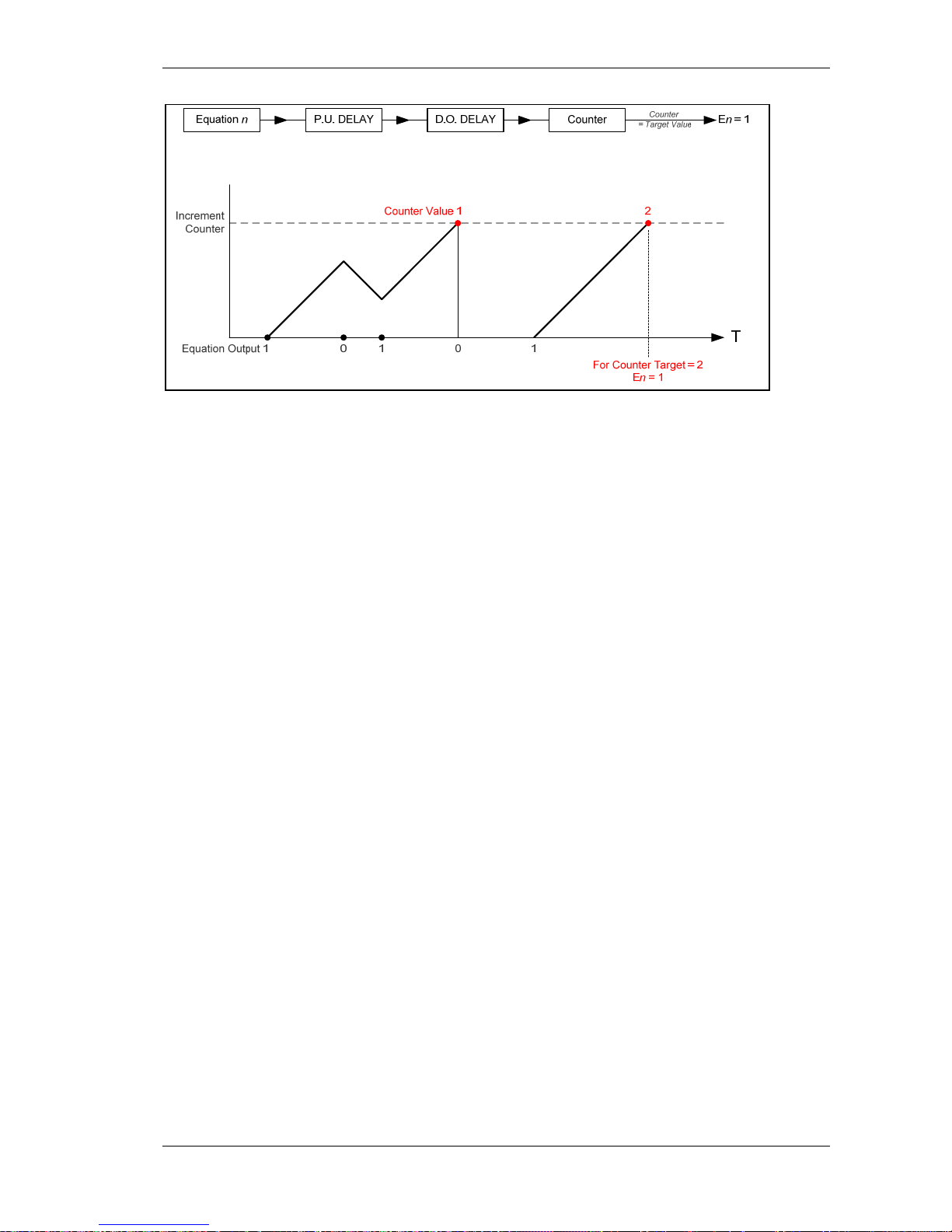
(1) Description of Operation 7SR224
©2009 Siemens Protection Devices Limited Page 51 of 66
P.U. DELAY
D.O
. DE
LA
Y
Figure 4.4-1 Sequence Diagram: Quick Logic PU/DO Timers (Counter Reset Mode Off)
When the count value = En Counter Target the output of the counter (En) = 1 and this value is held
until the initiating conditions are removed when En is instantaneously reset.
The output of En is assigned in the OUTPUT CONFIG>OUTPUT MATRIX menu where it can be
programmed to any binary output (O), LED (L) or Virtual Input/Output (V) combination.
Protection functions can be used in Quick Logic by mapping them to a Virtual Input / Output.
Refer to Section 7 – Applications Guide for examples of Logic schemes.
Page 52
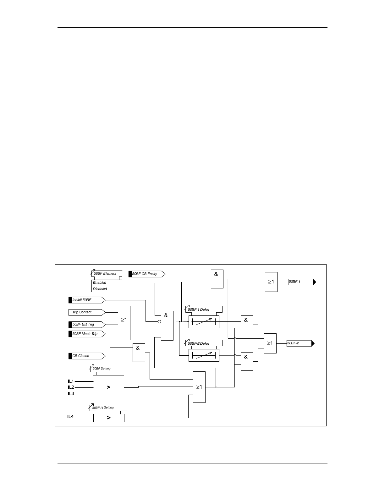
(1) Description of Operation 7SR224
Page 52 of 66 ©2009 Siemens Protection Devices Limited
Section 5: Supervision Functions
5.1 CIRCUIT BREAKER FAILURE (50BF)
The circuit breaker fail function has two time delayed outputs that can be used for combinations of re-
tripping or back-tripping. CB Fail outputs are given after elapse of the 50BF-1 Delay or 50BF-2 Delay
settings.
The circuit breaker fail protection time delays are initiated either from:
An output Trip Contact of the relay (MENU: OUTPUT CONFIG\BINARY OUTPUT
CONFIG\Trip Contacts), or
A binary input configured 50BF Ext Trip (MENU: INPUT CONFIG\BINARY INPUT
MATRIX\50BF Ext Trip).
A binary or virtual input assigned to 50BF Mech Trip (MENU: INPUT CONFIG\INPUT
MATRIX\ 50BF Mech Trip).
CB Fail outputs will be issued providing any of the 3 phase currents are above the 50BF Setting or
the current in the fourth CT is above 50BF-I4 for longer than the 50BF-n Delay setting, or for a
mechanical protection trip the circuit breaker is still closed when the 50BF-n Delay setting has expired
– indicating that the fault has not been cleared.
Both 50BF-1 and 50BF-2 can be mapped to any output contact or LED.
If the 50BF CB Faulty input (MENU: INPUT CONFIG\INPUT MATRIX\50BF CB Faulty) is energised
when a CB trip is given the time delays 50BF-n Delay will be by-passed and the output given
immediately.
Operation of the CB Fail elements can be inhibited from:
Inhibit 50BF A binary or virtual input.
Figure 5.1-1 Logi c Diagr am: Circuit Breaker Fail Protection (50BF)
Page 53

(1) Description of Operation 7SR224
©2009 Siemens Protection Devices Limited Page 53 of 66
5.2 VT SUPERVISION (60VTS)
1 or 2 Phase Failure Detection
Normally the presence of negative phase sequence (NPS) or zero phase sequence (ZPS) voltage in a
power system is accompanied by NPS or ZPS current. The presence of either of these sequence
voltages without the equivalent level of the appropriate sequence current is used to indicate a failure
of one or two VT phases.
The 60VTS Component setting selects the method used for the detection of loss of 1 or 2 VT phases
i.e. ZPS or NPS components. The sequence component voltage is derived from the line voltages;
suitable VT connections must be available. The relay utilises fundamental voltage measurement
values for this function.
The element has user settings 60VTS V and 60VTS I. A VT is considered to have failed where the
voltage exceeds 60VTS V while the current is below 60VTS I for a time greater than 60VTS Delay.
3 Phase Failure Detection
Under normal load conditions rated PPS voltage would be expected along with a PPS load current
within the circuit rating. Where PPS load current is detected without corresponding PPS voltage this
could indicate a three phase VT failure. To ensure these conditions are not caused by a 3 phase fault
the PPS current must also be below the fault level.
The element has a 60VTS V
PPS
setting, an 60VTS I
PPS
Load setting and a setting for 60VTS I
PPS
Fault. A VT is considered to have failed where positive sequence voltage is below 60VTS V
PPS
while
positive sequence current is above I
PPS
Load and below I
PPS
Fault level for more than 60VTS Delay
then a VT failure will be detected.
External MCB
A binary input can be set as Ext_Trig 60VTS to allow the 60VTS Delay element to be started from an
external MCB operating.
Once a VT failure condition has occurred the output is latched on and is reset by any of the following:-
Voltage is restored to a healthy state i.e. above V
PPS
setting while NPS voltage is below V
NPS
setting.
Ext Reset 60VTS A binary or virtual input, or function key and a VT failure condition no
longer exists.
Inhibit 60VTS A binary or virtual input.
Page 54
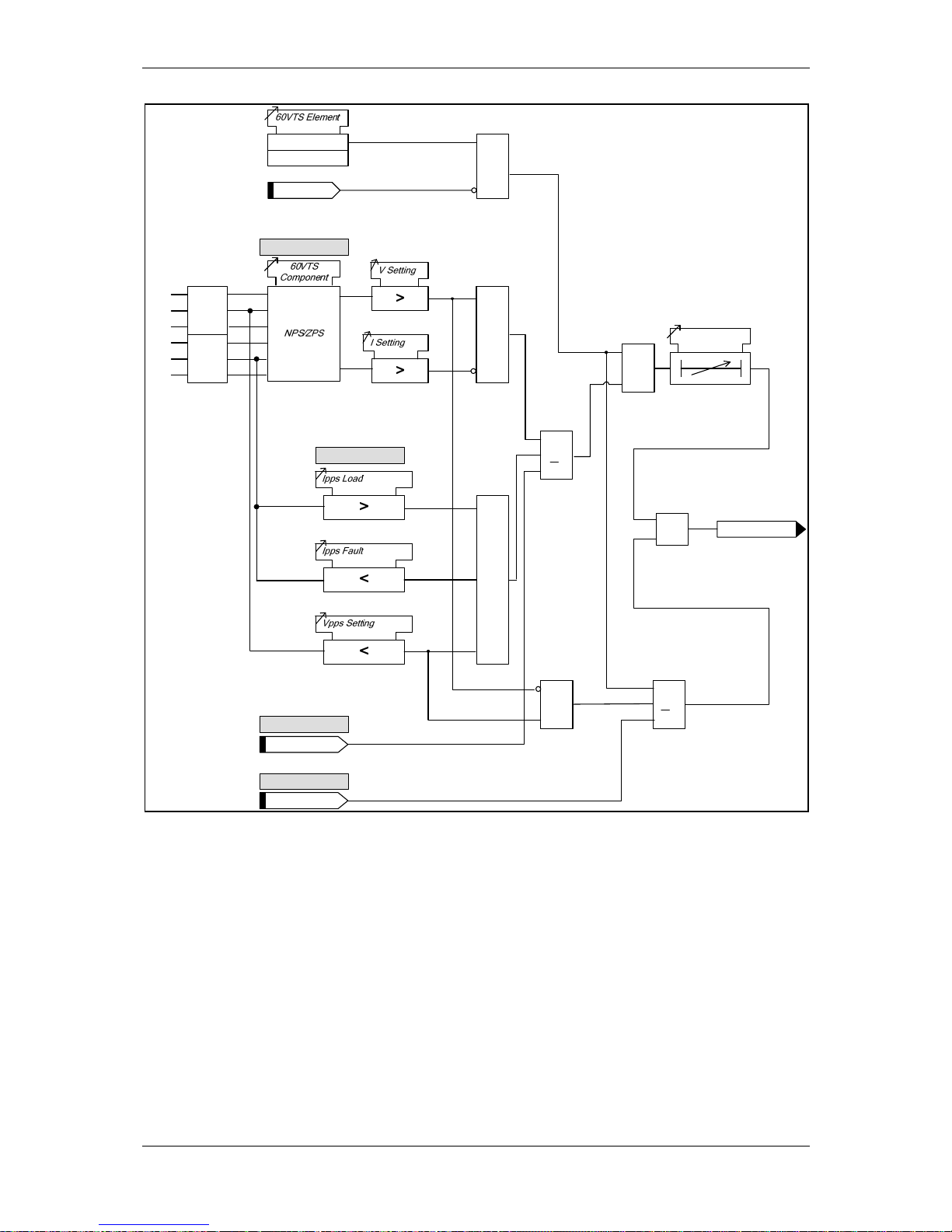
(1) Description of Operation 7SR224
Page 54 of 66 ©2009 Siemens Protection Devices Limited
Enabled
Disabled
&
&
&
>
1
60VTS Ext_Trig
&
S
R
Q
>1
60VTS Operated
&
60VTS Inhibit
1 or 2 Phase Fail
V
I
V1
I1
3 Phase Fail
I1
External Trigger
60VTS Ext_Reset
External Reset
60VTS Delay
VL1
VL2
VL3
Phase
Seq.
Filter
IL1
IL2
IL3
Phase
Seq.
Filter
V2
V0
I2
I0
V1
I1
Figure 5.2-1 Logic Diagram: VT Supervision Func tio n (60VTS )
Page 55
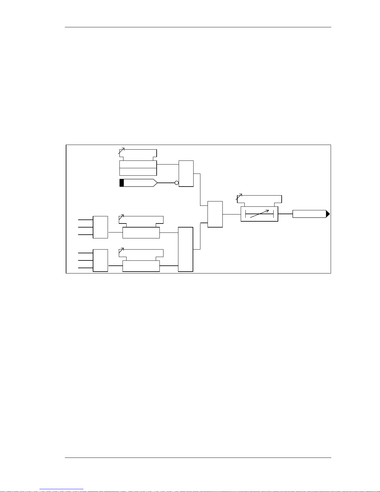
(1) Description of Operation 7SR224
©2009 Siemens Protection Devices Limited Page 55 of 66
5.3 CT SUPERVISION (60CTS)
Normally the presence of negative phase sequence (NPS) current in a power system is accompanied
by NPS voltage. The presence of NPS current without NPS voltage is used to indicate a current
transformer failure.
The element has a setting for NPS current level 60CTS Inps and a setting for NPS voltage level
60CTS Vnps If the negative sequence current exceeds its setting while the negative sequence voltage
is below its setting for more than 60CTS Delay then a CT failure output (60CTS Operated) is given.
Operation of the under/over voltage elements can be inhibited from:
Inhibit 60CTS A binary or virtual input.
&
60CTS Delay
VL1
VL2
VL3
NPS
Filter
V2
60CTS Vnps
<
IL1
IL2
IL3
NPS
Filter
I2
60CTS Inps
>
&
Inhibit 60CTS
60CTS Element
Enabled
Disabled
&
60CTS Operated
Figure 5.3-1 Logi c Diagr am: CT Supervision Function (60CTS)
Page 56
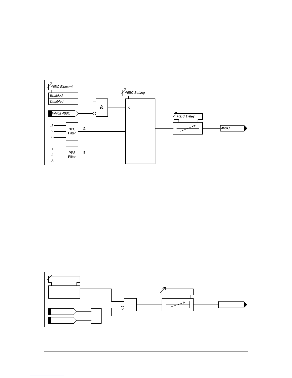
(1) Description of Operation 7SR224
Page 56 of 66 ©2009 Siemens Protection Devices Limited
5.4 BROKEN CONDUCTOR (46BC)
The element calculates the ratio of NPS to PPS currents. Where the NPS:PPS current ratio is above
46BC Setting an output is given after the 46BC Delay.
The Broken Conductor function can be inhibited from
Inhibit 46BC A binary or virtual input.
Figure 5.4-1 Logic Diagram: Broken Conduc tor Func tion (46BC)
5.5 TRIP CIRCUIT SUPERVISION (74TCS)
The relay provides three trip circuit supervision elements.
One or more binary inputs can be mapped to 74TCS-n. The inputs are connected into the trip circuit
such that at least one input is energised when the trip circuit wiring is intact. If all mapped inputs
become de-energised, due to a break in the trip circuit wiring or loss of supply an output is given.
The 74TCS-n Delay setting prevents failure being incorrectly indicated during circuit breaker
operation. This delay should be greater than the operating time of the circuit breaker.
The use of one or two binary inputs mapped to the same Trip Circuit Supervision element (e.g.
74TCS-n) allows the user to realise several alternative monitoring schemes – see ‘Applications Guide’.
TCS-n
Enabled
Disabled
&
74TCS-n
74TCS-n
74TCS-n Delay
≥1
74TCS-n
NOTE: Diagram shows two binary inputs mapped
to the same Trip Circuit Supervision element
Figure 5.5-1 Logic Diagram: Trip Circuit Super vision Featur e (74TCS)
Page 57
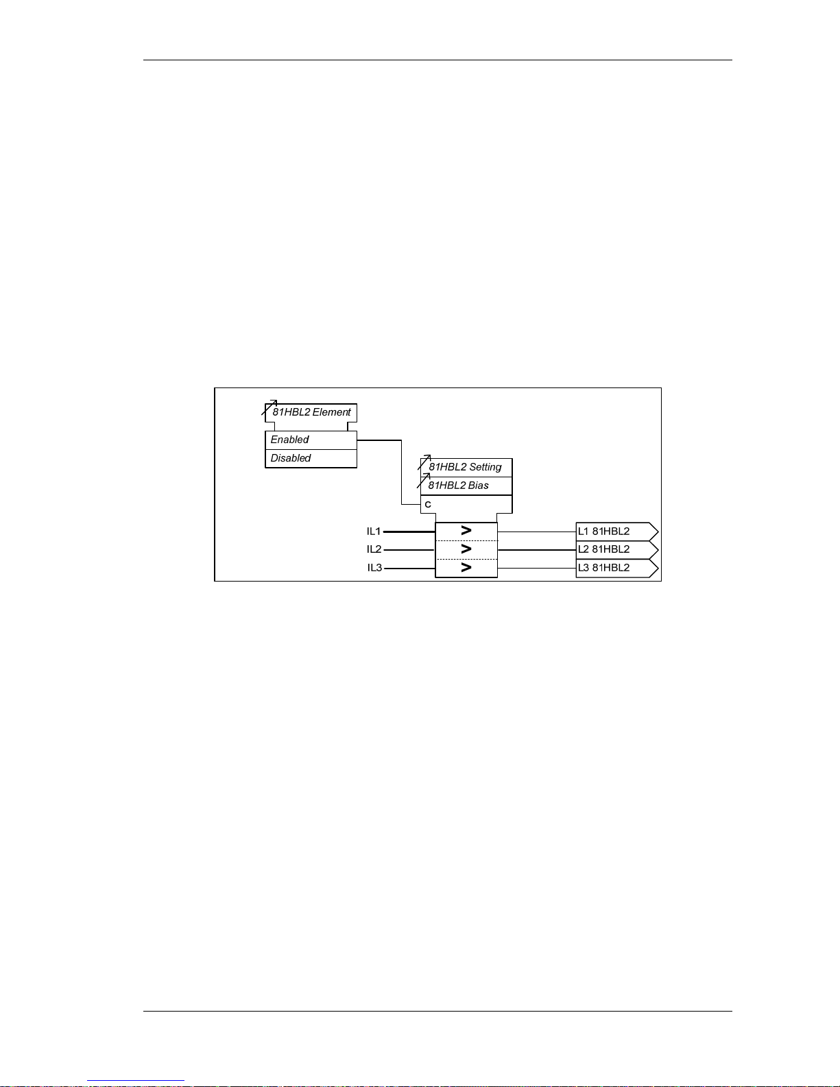
(1) Description of Operation 7SR224
©2009 Siemens Protection Devices Limited Page 57 of 66
5.6 INRUSH DETECTOR (81HBL2)
Inrush restraint detector elements are provided, these monitor the line currents.
The inrush restraint detector can be used to block the operation of selected elements during
transformer magnetising inrush conditions.
The 81HBL2 Bias setting allows the user to select between Phase, Sum and Cross methods of
measurement:
Phase Each phase is inhibited separately.
Sum With this method the square root of the sum of the squares of the second harmonic in
each phase is compared to each operate current individually.
Cross All phases are inhibited when any phase detects an inrush condition.
An output is given where the measured value of the second harmonic component is above the
81HBL2 setting.
Figure 5.6-1 Logic Diagram: Harmonic Block Feature (81HBL2)
Page 58
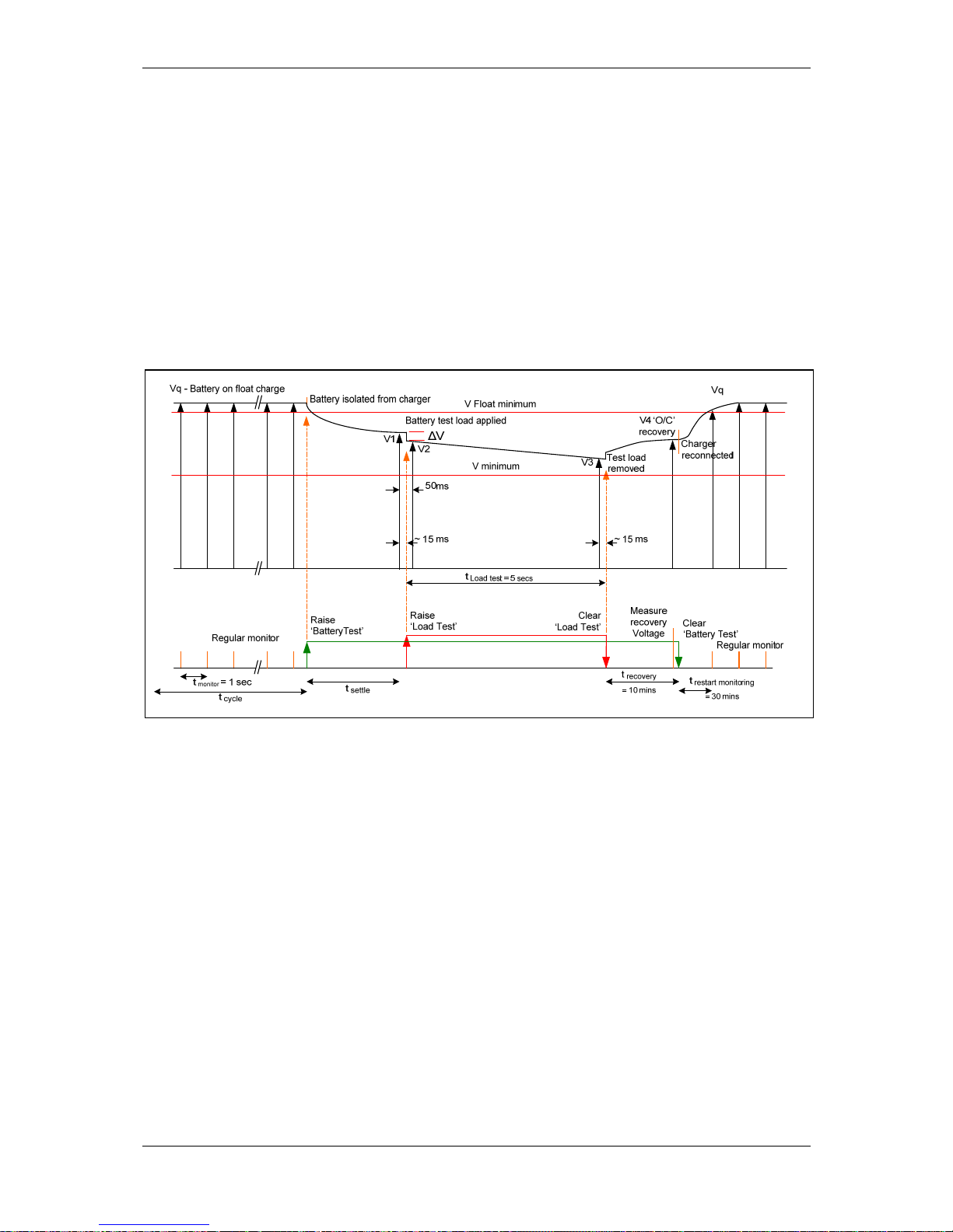
(1) Description of Operation 7SR224
Page 58 of 66 ©2009 Siemens Protection Devices Limited
5.7 BATTERY TEST
The DC battery voltage is constantly monitored by the relay. The output function Battery Healthy is
provided to indicate that the battery charging system is connected and functioning correctly by
measurement of the ‘Float Charge’ voltage level and comparison with the minimum float voltage
based on the Battery Nominal Voltage setting.
In addition to this, the relay can be used to apply a loading test to the battery system at a settable
periodic interval. The test sequence is shown below.
If a protection Pickup occurs at any time during the test, the test will be abandoned and the charging
system re-connected. The battery voltage level will be maintained such that the Recloser will be
capable of normal operation throughout the duration of the test. Battery tests can be executed at
manual request from a binary input or from the Control Menu of the relay. If the time elapsed since the
previous battery test is less than 12 hours, the test will not execute and Test Aborted will be displayed
on the Battery Condition meter.
Figure 5.7-1 Battery Test timing diagram
When the test is required, the output Battery Test is raised to interface with external equipment. This
signal is used to disconnect the charging system and the battery is allowed to settle for a fixed period
of 30 minutes. The battery voltage with no load is then measured (V1) and the output Battery Load
Test is then raised. This is used to connect the resistive load to the battery and the voltage is
measured again after 500ms (V2). This voltage is used to asses the battery internal resistance and the
resistance of connections. If V1-V2 (ΔV) is greater than the Battery Volts Drop setting the test will be
considered as a failure and the test stopped, otherwise voltage is measured again after a further 5
seconds with the load resistance connected. This voltage, (V3), is compared to V2 and must not differ
by more than 2 volts or the test will be stopped and recorded as a fail. The load is then disconnected,
by the drop-off of the Battery Load Test output and a 10 minute recovery time applied before the
voltage is measured again (V4). This voltage must not differ from the pre-test voltage by more than 0.5
volts or Recovery Fail output will be raised. The Battery Test output is now cleared which will
reconnect the charging system to allow the system to return to normal. The quiescent voltage
monitoring will resume after 30 minutes.
Page 59
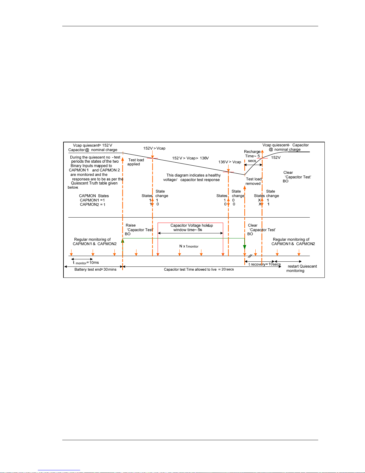
(1) Description of Operation 7SR224
©2009 Siemens Protection Devices Limited Page 59 of 66
5.8 CAPACITOR TEST
The actuator mechanism of the recloser can be driven from a charged capacitor network. The
condition of the capacitors is monitored externally to the relay and the interface to the relay is in the
form of two binary signals which are driven by undervoltage detectors as shown below. These inputs
are CapMon Input 1 and CapMon Input 2.
In the quiescent state, both logical inputs should be in the ‘1’ state and the detection of ‘0’ on both
inputs will trigger the CapacitorSupplyFail output.
In addition to the monitoring during quiescent conditions, the state of the inputs can be monitored to
assess capacitor condition during an externally applied discharge test. When the Cap Element setting
is Enabled, the sequence is executed automatically, 30 minutes after completion of a successful
battery test. The sequence can be started manually on demand by energising the Capacitor Test
binary input. If any protection element pickup occurs at any time during the capacitor test sequence,
the sequence will be terminated.
Figure 5.8-1 Capacitor Test timing diagram
When the test is required, the output Cap Test Active is raised. This is used externally to start the
discharge test. When the voltage reduces to the higher voltage detector, the relay binary inputs
CapMon Input 2 will change to state ‘0’ from the quiescent ‘1’. CapMon Input 1 will remain at the ‘1’
state. The relay recognises this 1-0 condition and starts a timer which runs for the Cap Holdup Time.
If the CapMon Input 1 changes state to ‘0’ during this time, the test is recorded as a fail and the relay
goes to the recovery state as described below. If the timer expires with the 1-0 condition still
maintained, the test is considered as a pass. The sequence now enters the recovery state and the
Cap Test Active output is cleared causing the external discharge test to end The Capacitor voltage
will now recover and the quiescent 1-1 state for CapMon Input 1 and CapMon Input 2 will be reestablished. If the 1-1 state is not achieved at the end of the 10 second recovery time, the Cap
Recovery Fail output and the Capacitor Only Trip output are raised and the reclose function of the
relay are internally blocked. Normal continuous monitoring of the quiescent state will be resumed 10
seconds after the reset of the Cap Test Active output.
Page 60
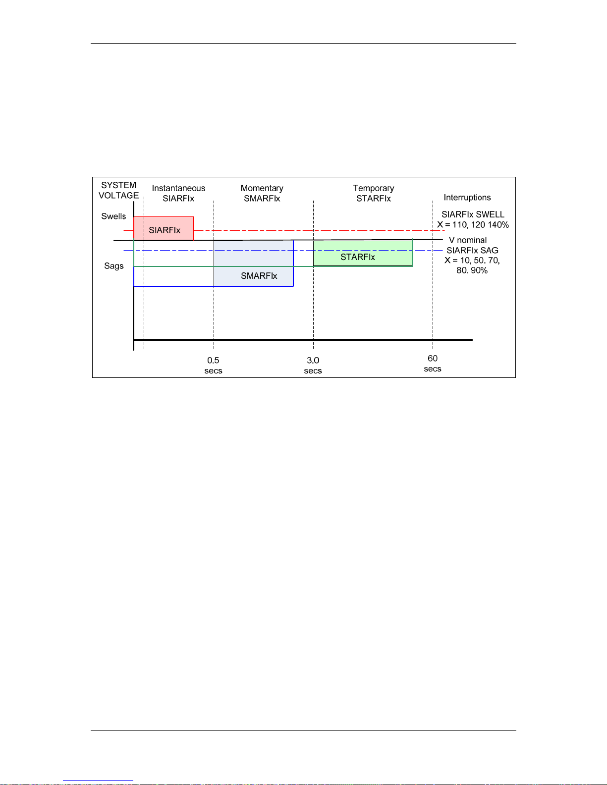
(1) Description of Operation 7SR224
Page 60 of 66 ©2009 Siemens Protection Devices Limited
5.9 POWER QUALITY (27S/59S)
Voltage sag (27S) and voltage swell (59S) elements monitor the power supply quality.
The elements monitor the deviation of the voltage from the nominal value and the duration of this
under or over voltage in accordance with IEEE 1159.
Figure 5.9-1 Sag and Swell Indices - IEEE 1159
5.10 DEMAND
Maximum, minimum and mean values of line currents and voltage (where applicable) are available as
instruments which can be read in the relay INSTRUMENTS MENU or via Reydisp.
The Gn Demand Log Time Sync when set as ENABLED configures the Demand Log Update Period
(see below) equal to the DATA STORAGE > Data Log Period setting.
The Gn Demand Log Update Period setting is used to define the time/duration after which the
instrument is updated. The updated value indicates the maximum, minimum and mean values for the
defined period. Note that this setting can be over-ridden by the Gn Demand Log Time Sync setting.
The Gn Demand Window setting defines the maximum period of time over which the demand values
are valid. A new set of demand values is established after expiry of the set time.
The Gn Demand Window Type can be set to FIXED or PEAK.
When set to FIXED the maximum, minimum and mean values demand statistics are
calculated over fixed Window duration. At the end of each window the internal statistics
are reset and a new window is started.
When set to PEAK the maximum and minimum values within the Demand Window time
setting is recorded.
Page 61

(1) Description of Operation 7SR224
©2009 Siemens Protection Devices Limited Page 61 of 66
Section 6: Other Features
6.1 DATA COMMUNICATIONS
Two communication ports, COM1 and COM2 are provided. RS485 connections are available on the
terminal blocks at the rear of the relay (COM1). A USB port, (COM 2), is provided at the front of the
relay for local access using a PC.
Other rear mounted communication ports are available as an optional extra - two fibre optic
communication ports with ST connectors plus IRIG B (COM 3 and COM 4), a RS232 port plus IRIG B
(COM 3) or a RS485 port plus IRIG B (COM 3).
Communication is compatible with Modbus-RTU, IEC60870-5-103 FT 1.2 and DNP 3.0 transmission
and application standards.
For communication with the relay via a PC (personal computer) a user-friendly software package,
Reydisp Evolution, is available to allow transfer of relay settings, waveform records, event records,
fault data records, Instruments/meters and control functions. REYDISP EVOLUTION is compatible
with IEC60870-5-103.
Data communications operation is described in detail in Section 4 of this manual.
6.2 CB MAINTENANCE
Several CB trip operations counters are provided:
CB Total Trip Count:
Increments on each trip command issued. During an
auto-reclose sequence, when the target count is
reached the relay will perform one Delayed Trip and
lockout*.
CB Delta Trip Count: Additional counter which can be reset independently of
the Total Trip Counter. This can be used, for example,
for recording trip operations between visits to a
substation.
CB Count to AR Block:
Displays the number of CB trips experienced by the
CB. When the target is reached the relay will only do 1
Delayed Trip to Lockout.
CB Frequent Ops Count Logs the number of trip operations in a rolling window
period of one hour. During an auto-reclose sequence,
when the target count is reached the relay will perform
one Delayed Trip and lockout*.
CB LO Handle Ops
Displays the number of CB (lock out) LO Handle Ops
experienced by the CB. When the target is reached the
relay will only do 1 Delayed Trip to Lockout.
*NB: If Delayed Trips are not assigned in the AUTORECLOSE PROT’N menu the relay will not trip.
An I
2
t counter is also included; this can provide an estimation of contact wear and maintenance
requirements. The I
2
t value at the time of trip is added to the previously stored value.
Binary outputs can be mapped to each of the above counters, these outputs are energised when the
user defined Count Target or Alarm Limit is reached.
The counters do not increment for manual operations.
Page 62

(1) Description of Operation 7SR224
Page 62 of 66 ©2009 Siemens Protection Devices Limited
6.3 OUTPUT MATRIX TEST
The feature is only visible from the Relay fascia and allows the user to operate the relays functions.
The test of the function will automatically operate any Binary Inputs or LED’s already assigned to that
function.
Any protection function which is enabled in the setting menu will appear in the Output Matrix Test.
6.4 DATA STORAGE
6.4.1 General
The relay stores three types of data: relay event records, analogue/digital waveform records and fault
records. Data records are backed up in non-volatile memory and are permanently stored even in the
event of loss of auxiliary d.c. supply voltage.
6.4.2 Event Records
The event recorder feature allows the time tagging of any change of state (Event) in the relay. As an
event occurs, the actual event condition is logged as a record along with a time and date stamp to a
resolution of 1 millisecond. There is capacity for a maximum of 5000 event records that can be stored
in the relay and when the event buffer is full any new record will over-write the oldest. Stored events
can be erased from the front fascia via DATA STORAGE>Clear Events setting or using Reydisp
Evolution via Relay > Events > Reset Events.
The following events are logged:
Change of state of Binary outputs.
Change of state of Binary inputs.
Change of Settings and Settings Group
Change of state of any of the control functions of the relay.
All events can be retrieved over the data communications channel(s) and can be displayed in the
‘Reydisp Evolution’ package in chronological order, allowing the sequence of events to be viewed.
Events are also made available spontaneously to an IEC 60870-5-103, Modbus RTU or DPN 3.0
compliant control system.
For a complete listing of events available in each model, refer to Technical Manual section 4 ‘Data
Comms’.
6.4.3 Waveform Records.
Relay waveform storage can be triggered either after user selected relay operations, from the relay
fascia, from a suitably programmed binary input or via the data comms channel(s). The stored
analogue and digital waveforms illustrate the system and relay conditions at the time of trigger.
In total the relay provides 10 seconds of waveform storage, this is user selectable to 1 record of 10
seconds duration, 2 records of 5 seconds duration, 5 records of 2 seconds duration or 10 records of 1
second duration. When the waveform recorder buffer is full any new waveform records will over-write
the oldest. The most recent record is Waveform 1.
As well as defining the stored waveform record duration the user can select the percentage of the
waveform storage prior to triggering.
The waveform recorder samples at a rate of 32 samples per cycle (1600Hz).
Stored waveforms can be erased using the DATA STORAGE>Clear Waveforms setting or using
Reydisp Evolution via Relay > Waveform > Reset Waveform Records.
Page 63

(1) Description of Operation 7SR224
©2009 Siemens Protection Devices Limited Page 63 of 66
6.4.4 Fault Records
Up to ten fault records can be stored and displayed on the Fascia LCD.
Fault records provide a summary of the relay status at the time of trip, i.e. the element that issued the
trip, any elements that were picked up, the fault type, LED indications, date and time. The Max Fault
Rec. Time setting sets the time period from fault trigger during which the operation of any LEDs is
recorded.
When examined together the event records and the fault records will detail the full sequence of events
leading to a trip.
Fault records are stored in a rolling buffer, with the oldest faults overwritten. The fault storage can be
cleared with the DATA STORAGE>Clear Faults setting or using Reydisp Evolution via Relay > Data
Records > Reset Data Log Record.
6.4.5 Data Log
The Data log feature can be used to build trend and maximum/minimum demand records. Up to
10,080 individual time stamped records of each phase current and voltage (where fitted) analogue
signal are recorded and stored at a user defined rate e.g. 7 days @ 1 minute intervals and > 1 year @
1 hour intervals.
6.5 METERING
The metering feature provides real-time data available from the relay fascia in the ‘Instruments Mode’
or via the data communications interface.
For a detailed description refer to Technical Manual Section 2 – Settings and Instruments.
Page 64

(1) Description of Operation 7SR224
Page 64 of 66 ©2009 Siemens Protection Devices Limited
6.6 OPERATING MODE
The relay has three operating modes, Local, Remote and Out of Service. The following table
identifies the functions operation in each mode.
The modes can be selected by the following methods:
SYSTEM CONFIG>RELAY MODE setting, a Binary Input or Command
Table 6-1 Operation Mode
OPERATION REMOTE MODE LOCAL MODE SERVICE MODE
Control
Rear Ports Enabled Disabled Disabled
Fascia (Control Mode) Disabled Enabled Disabled
USB Disabled Enabled Disabled
Binary Inputs Setting Option Setting Option Enabled
Binary Outputs Enabled Enabled Disabled
Reporting
Spontaneous
IEC Enabled Enabled Disabled
DNP Enabled Enabled Disabled
General Interogation
IEC Enabled Enabled Disabled
DNP Enabled Enabled Disabled
MODBUS Enabled Enabled Enabled
Changing of Settings
Rear Ports Enabled Disabled Enabled
Fascia Enabled Enabled Enabled
USB Disabled Enabled Enabled
Historical Information
Waveform Records Enabled Enabled Enabled
Event Records Enabled Enabled Enabled
Fault Information Enabled Enabled Enabled
Setting Information Enabled Enabled Enabled
6.7 CONTROL MODE
This mode provides convenient access to commonly used relay control and test functions. When any
of the items listed below are selected control is initiated by pressing the ENTER key. The user is
prompted to confirm the action, again by pressing the ENTER key, before the command is executed.
Control Mode commands could be password protected using the Control Password function – see
section 6.8.
Commands available in the Control Mode are:
Open CB
Close CB
79 In/Out
79 Trip and Reclose
Page 65

(1) Description of Operation 7SR224
©2009 Siemens Protection Devices Limited Page 65 of 66
79 Trip & Lockout
Hotline Work In/Out
E/F In/Out
SEF In/Out
Instantaneous Protection In/Out
Battery Test Required
6.8 REAL TIME CLOCK
Time and date can be set either via the relay fascia using appropriate commands in the System Config
menu, via the data comms channel(s) or via the optional IRIG-B input. Time and date are maintained
while the relay is de-energised by a back up storage capacitor.
The default date is set at 01/01/2000 deliberately to indicate the date has not yet been set. When
editing the Time, only the hours and minutes can be edited. When the user presses ENTER after
editing the seconds are zeroed and the clock begins running.
6.8.1 Time Synchronisation - IEC 60870-5-103 & DNP3.0
Where the data comms channel(s) is connected the relay can be directly time synchronised to the
nearest second or minute using the IEC 60870-5-103 & DNP3.0 global time synchronisation. This can
be from a dedicated substation automation system or from ‘Reydisp Evolution’ communications
support software.
6.8.2 Time Synchronisation – Binary Input
A binary input can be mapped Clock Sync from BI. The seconds or minutes will be rounded up or
down to the nearest value when the BI is energised. This input is leading edge triggered.
6.8.3 Time Synchronisation – IRIG-B (Optional)
A BNC connector on the relay rear provides an isolated IRIG-B time synchronisation port. The IRIG-B
input expects a modulated 3-6 Volt signal and provides time synchronisation to the nearest
millisecond.
6.9 SETTINGS GROUPS
The relay provides eight groups of settings – Group number (Gn) 1 to 8. At any one time only one
group of settings can be ‘active’ – SYSTEM CONFIG>Active Group setting.
It is possible to edit one group while the relay operates in accordance with settings from another
‘active’ group using the View/Edit Group setting.
Some settings are independent of the active group setting i.e. they apply to all settings groups. This is
indicated on the top line of the relay LCD – where only the Active Group No. is identified. Where
settings are group dependent this is indicated on the top line of the LCD by both the Active Group
No. and the View Group No. being displayed.
A change of settings group can be achieved either locally at the relay fascia, remotely over the data
comms channel(s) or via a binary input. When using a binary input an alternative settings group is
selected only whilst the input is energised (Select Grp Mode: Level triggered) or latches into the
selected group after energisation of the input (Select Grp Mode: Edge triggered).
Page 66

(1) Description of Operation 7SR224
Page 66 of 66 ©2009 Siemens Protection Devices Limited
6.10 PASSWORD FEATURE
The relay incorporates two levels of password protection – one for settings, the other for control
functions.
The programmable password feature enables the user to enter a 4 character alpha numeric code to
secure access to the relay functions. The relay is supplied with the passwords set to NONE, i.e. the
password feature is disabled. The password must be entered twice as a security measure against
accidental changes. Once a password has been entered then it will be required thereafter to change
settings or initiate control commands. Passwords can be de-activated by using the password to gain
access and by entering the password NONE. Again this must be entered twice to de-activate the
security system.
As soon as the user attempts to change a setting or initiate control the password is requested before
any changes are allowed. Once the password has been validated, the user is ‘logged on’ and any
further changes can be made without re-entering the password. If no more changes are made within
1 hour then the user will automatically be ‘logged off’, re-enabling the password feature.
The Settings Password prevents unauthorised changes to settings from the front fascia or over the
data comms channel(s). The Control Password prevents unauthorised operation of controls in the
relay Control Menu from the front fascia.
The password validation screen also displays a numerical code. If the password is lost or forgotten,
this code should be communicated to Siemens Protection Devices Ltd. and the password can be
retrieved.
 Loading...