

Siemens 7SR11 Argus, 7SR12 Argus User Manual

Answers for energy
7SR11 and 7SR12 Argus
Overcurrent Relays
Reyrolle
Protection
Devices
Siemens Protection Devices Limited 2
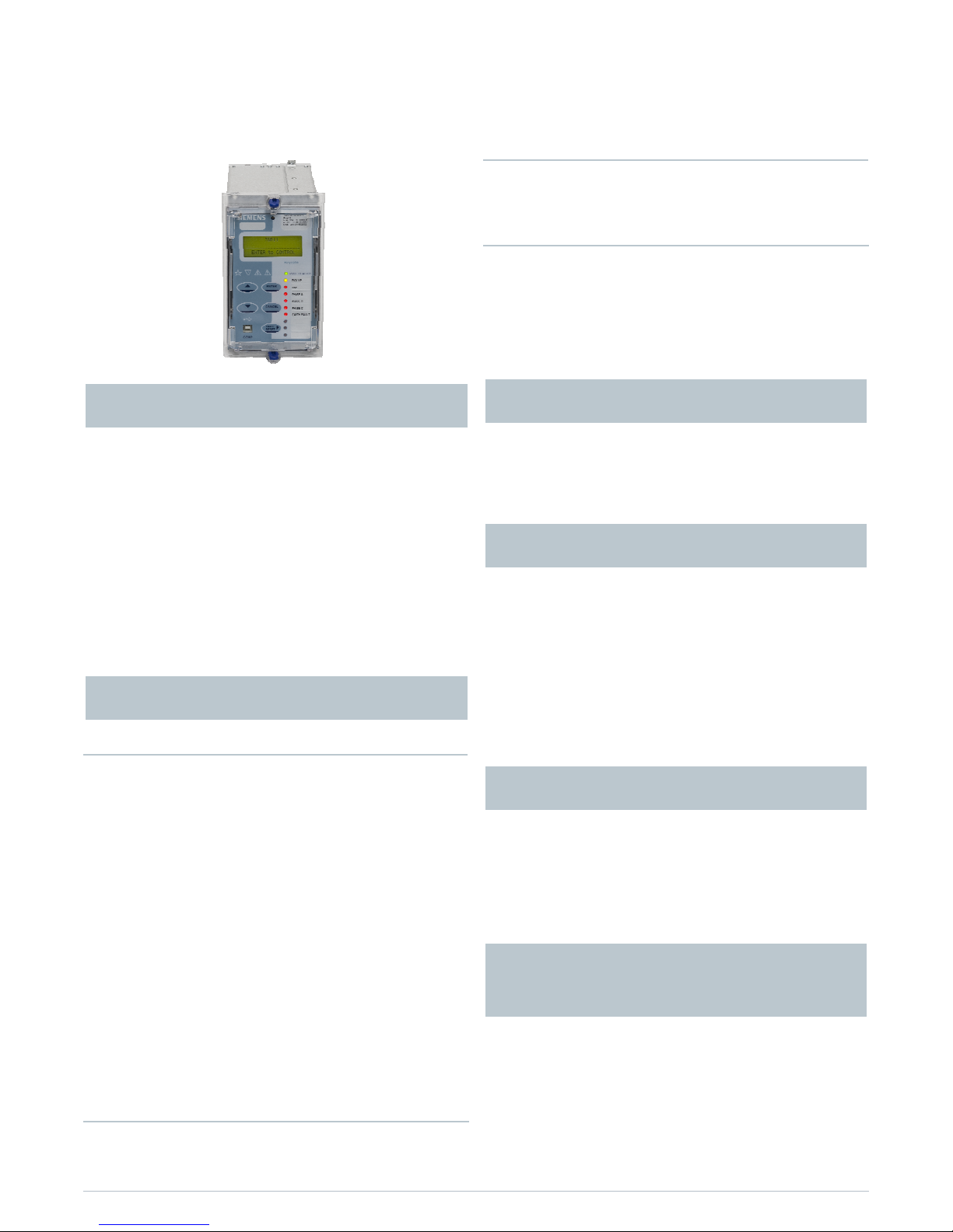
The 7SR11 & 7SR12 are overcurrent protection relays
developed to enhance the Argus family of products by
providing a familiar product using the latest generation of
hardware technology.
The 7SR11 overcurrent and earth fault relays and the 7SR12
directional relays are available in single and four pole
variants.
Housed in a 4U high, size E4 case, these relays provide
protection, monitoring, instrumentation and metering with
integrated input and output logic, data logging & fault
reports. Communication access to the relay functionality is
via a front USB port for local PC connection or rear electrical
RS485 port for remote connection.
Protection
37 Undercurrent
46BC Broken Conductor / Load Unbalance
46NPS Negative Phase Sequence Overcurrent
49 Thermal Overload
50 Instantaneous Overcurrent
50G/N/SEF Instantaneous Earth Fault
50BF Circuit Breaker Fail
51 Time Delayed Overcurrent
51G/N/SEF Time Delayed Measured/Derived/Sensitive Earth
Fault
64H High Impedance REF
27/59 Under/Over Voltage
47 Negative Phase Sequence Voltage
51V Voltage Controlled Overcurrent
59N Neutral Voltage Displacement
67/50 Directional Instantaneous Overcurrent
67/50G/N Directional Instantaneous Earth Fault
67/51 Directional Time Delayed Overcurrent
67/51G/N Directional Time Delayed Earth Fault
81HBL2 Inrush Detector
Supervision
60CTS CT Supervision
74T/CCS Trip & Close Circuit Supervision
60VTS VT Supervision
Control
79 Auto Reclose
86 Lockout
CB Control
Features
Cold Load Settings
Four Settings Groups
Password Protection – 2 levels
User Programmable Logic
Self Monitoring
Circuit Breaker Trip and Maintenance Counter
Tri p Tim ers
20 Character x 4 Line Backlit LCD
Menu Navigation Keys
9 User Programmable Tri-colour LEDs
User Language Configuration
Primary/Secondary Current Phases and Earth
Direction
Primary/Secondary Line and Phase Voltages
Apparent Power and Power Factor
Real and Reactive Power
W Hr & VAr Hr Forward and Reverse
Historical Demand Record
Positive Phase Sequence (PPS) Voltage & Current
Negative Phase Sequence (NPS) Voltage & Current
Zero Phase Sequence (ZPS) Voltage
1 CT 3 Binary Inputs 5 Binary Outputs
4 CT 3 Binary Inputs 5 Binary Outputs
4 CT 6 Binary Inputs 8 Binary Outputs
1 CT 3 VT 3 Binary Inputs 5 Binary Outputs
4 CT 3 VT 3 Binary Inputs 5 Binary Outputs
4 CT 3 VT 6 Binary Inputs 8 Binary Outputs
Front USB port + Rear RS485 port
Protocols - IEC60870-5-103, DNP3.0 or Modbus RTU
Event Records – User Configurable
Fault Records
Waveform Records
Measurands
Commands
Time Synchronism
Viewing and Changing Settings
7SR11 and 7SR12 Argus
Overcurrent Relays
Description
User Interface
Data Storage and
Communication
Hardware
Monitoring Functions
Function Overview
Siemens Protection Devices Limited 3
The Argus is a numerical overcurrent protection relay
intended for use on distribution and industrial networks. It
provides a highly comprehensive functional software
package with a range of integral application functions aimed
at reducing installation, wiring and engineering time.
An extensive range of metered values can be viewed on the
front LCD or at a remote point via the communication
channel.
The integrated control feature allows operation of a single
circuit breaker and monitoring of its trip and close circuits.
FUNCTION
FUNCTIONAL
REQUIREMENT
7SR1101-1*A12-**A0
7SR1101-3*A12-**A0
7SR1102-1*A12-**A0
7SR1102-3*A12-**A0
7SR1204-2*A12-**A0
7SR1204-4*A12-**A0
7SR1205-2*A12-**A0
7SR1205-4*A12-**A0
27 Undervoltage ■■■
■
37 Undercurrent ■■ ■
■
46BC Broken Conductor / Load Unbalance ■■ ■
■
46NPS
Negative Phase Sequence
Overcurrent
■■ ■
■
47 Negative Phase Sequence Voltage ■■■
■
49 Thermal Overload ■■ ■
■
50 Instantaneous Overcurrent ■■ ■
■
50G Measured Instantaneous Earth Fault ■■■■
50SEF
Measured Instantaneous Sensitive
Earth Fault
■■■
■
50N Derived Instantaneous Earth Fault ■■ ■
■
50BF CB Failure ■■■■■■■
■
51 Time Delayed Overcurrent
■■ ■
■
51G Measured Time Delayed Earth Fault ■■■■
51SEF
Measured Time Delayed Sensitive
Earth Fault
■■■
■
51N Derived Time Delayed Earth Fault ■■ ■
■
59 Overvoltage ■■■
■
59N Neutral Voltage Displacement ■■■
■
64H
High Impedance Restricted Earth
Fault
■■■■■■■
■
67 Directional Overcurrent ■■■
■
67G Directional Measured Earth Fault ■■
67SEF Directional Sensitive Earth Fault ■■
■
67N Directional Derived Earth Fault ■■
■
CONTROL / MONITOR
51c Cold Load - Phase Only ■■ ■■
60CTS CT Supervision ■■ ■■
60VTS VT Supervision ■■■■
74T/CCS Trip & Close Circuit Supervision ■■■■■■■■
79 Autorec lose □□ □□
86 Lockout ■■■■■■■■
Key - ■ - Included as standard
□ - Ordering option
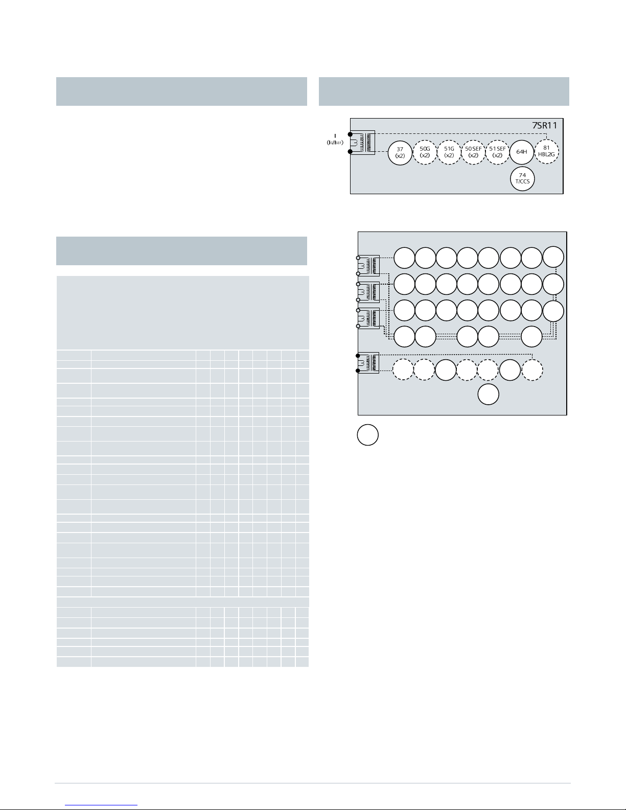
Fig 1. Single Pole Overcurrent Relay
7SR11
37
(x2)
49
50
(x2)51(x2)
50G
(x2)
51G
(x2)
50
BF
50N
(x2)
51N
(x2)
46
BC
46
NPS
(x2)
81
HBL2
37
(x2)
49
50
(x2)
50
BF
81
HBL2
37
(x2)
49
50
(x2)
50
BF
81
HBL2
74
T/CCS
51
(x2)
51
(x2)
81
HBL2
N
81
HBL2
G
I
4
(IG/ISEF)
IL1
(IA)
IL2
(IB)
IL3
(IC)
60
CTS
60
CTS
60
CTS
50
SEF
(x2)
51
SEF
(x2)
64H
50
BF
79
Optional
51c
51c
51c
Fig 2. Four Pole Overcurrent Relay
Application 7SR11 Functional Diagrams
Function Matrix
Siemens Protection Devices Limited 4
VL1
VL2
VL3
67/
50 G
(x4)
67/
51 G
(x4)
64 H
74
T/
CCS
81H
BL 2
67/
50 SE
F(x2)
67/
51 S E
F(x2)
59 N
(x2)
47
(x2)
27
59
(x 4)
27
59
(x 4)
27
59
(x 4)
7SR12
37
(x2)
I1
(I
G/ISEF)
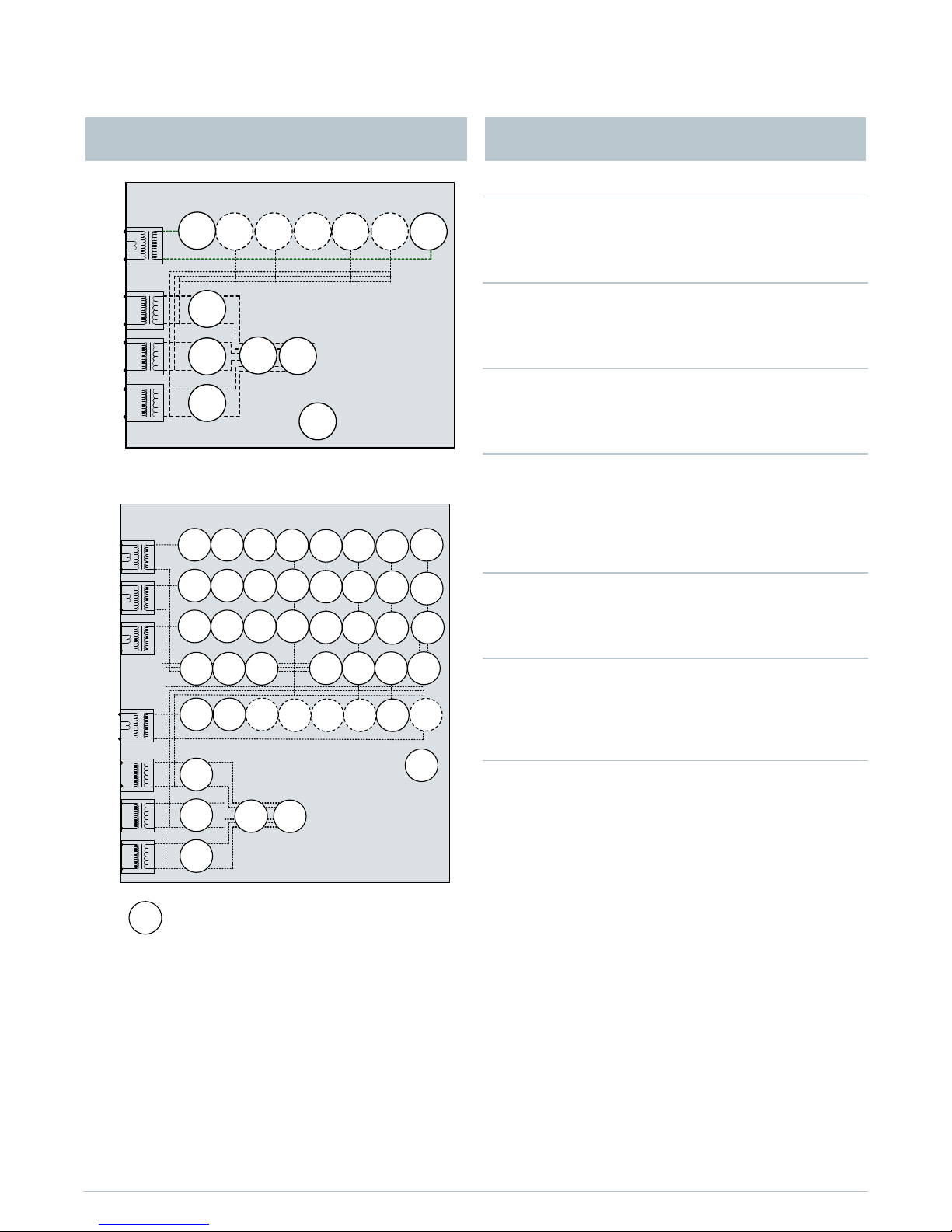
Fig 3. Single Pole Directional Relay
7SR12
64H
46
BC
46
NPS
(x2)
37
(x2)
49
50
BF
VL1
VL2
VL3
IL1
37
(x2)
49
50
BF
IL2
37
(x2)
49
50
BF
IL3
60
CTS60VTS
I4
74
T/CCS
67/
50
(x4)
67/
51
(x4)
67/
50N
(x4)
67/
50
(x4)
67/
50
(x4)
67/
51
(x4)
67/
51
(x4)
67/
51N
(x4)
67/
50G
(x4)
67/
51G
(x4)
27
59
(x4)
27
59
(x4)
27
59
(x4)
59N
47
79
Optional
50
BF
50
BF
37
81HBL
2
81HBL
2
81HBL
2
51V
51V
51V
67/
50SEF(
x2)
67/
51SEF(
x2)
81HBL
2
51c
51c
51c
Fig 4. Four Pole Directional Overcurrent Relay
Notes
1. Items shown dotted are only available in some
models; please refer to the Ordering Information
Section.
2. The use of some functions are mutually exclusive
27/59 Under/Over Voltage
Each element has settings for pickup level, drop-off level and
Definite Time Lag (DTL) delays. Operates if voltage exceeds
setting for duration of delay.
37 Undercurrent
Each element has settings for pickup level and Definite Time
Lag (DTL) delays. Operates if current falls below setting for
duration of delay.
46BC Phase Unbalance/Broken Conductor
Element has settings for pickup level and DTL delay. With the
circuit breaker closed, if the NPS:PPS current ratio is above
setting this could be due to a broken conductor.
46NPS Negative Phase Sequence Overcurrent
Each element has user settings for pickup level and IDMTL or
DTL delay, operates if NPS current exceeds setting and delay.
NPS current elements can be used to detect unbalances on
the system or remote earth faults when a delta-star
transformer is in circuit.
47 Negative Phase Sequence Voltage
Each element has settings for pickup level and Definite Time
Lag (DTL) delays. Operates if NPS voltage exceeds setting for
duration of delay.
49 Thermal Overload
The thermal algorithm calculates the thermal states from the
measured currents and can be applied to lines, cables and
transformers. Alarm outputs are given for thermal overload
and thermal capacity.
50BF Circuit Breaker Fail
The circuit breaker fail function may be triggered from an
internal trip signal or from a binary input. Line currents and
earth currents are monitored following a trip signal and an
output is issued if any current is still detected, above setting,
after a specified time interval. Alternatively, if the trip is
from a mechanical protection the circuit breaker position can
be used to determine a failure. A second time delay is
available to enable another stage to be utilized if required.
An input is also available to bypass the time delays when the
circuit breaker is known to be faulty.
Description of Functionality 7SR12 Functional Diagrams
Siemens Protection Devices Limited 5
50/51 Phase Fault
50 INST/DTL and 51 IDMTL/DTL elements provide overcurrent
protection, each with independent settings for pickup
current, time-multiplier (51) and time-delays. User can select
IEC or ANSI time current characteristics. The IDMT stage has
a user programmable reset characteristic, either DTL or
shaped current ~ time reset characteristic, to improve
grading with electromechanical protection.
50G/51G/50N/51N Earth Fault/Sensitive Earth Fault
Two earth fault measurement modes are available. One
mode directly measures the earth current from an
independent CT, or the residual connection of the 3 line CTs.
This input can be ordered as either earth fault or sensitive
earth fault (50G/51G).
The second mode derives the earth current internally from
the 3 phase CT inputs to give earth fault (50N/51N). 50
INST/DTL and 51 IDMTL/DTL elements provide overcurrent
protection, each with independent settings for pickup
current, time-multiplier (51) and time-delays. User can select
IEC or ANSI time current characteristics. The IDMT stage has
a user programmable reset characteristic either DTL or
shaped current ~ time reset characteristic to improve grading
with electromechanical protection.
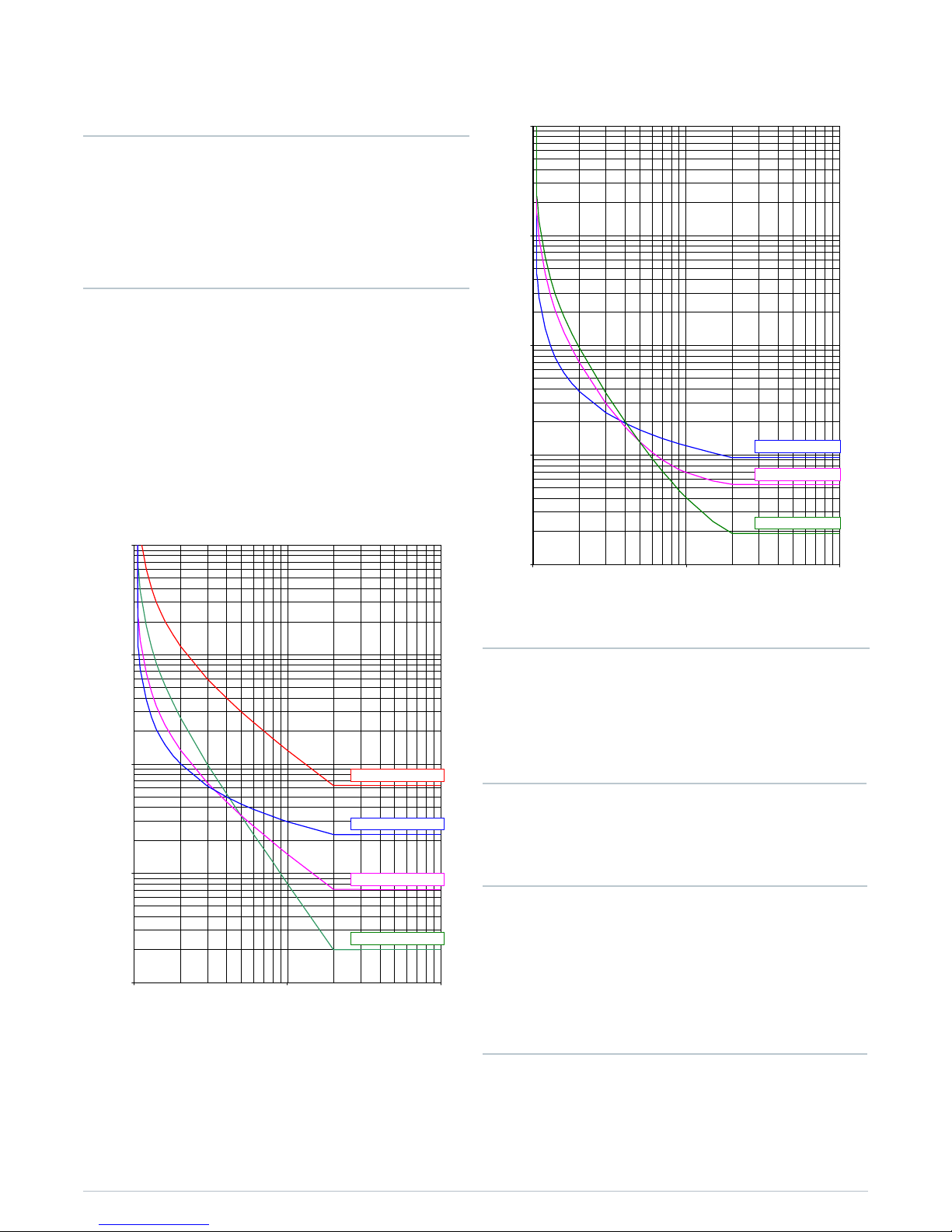
0.1
1
10
100
1000
110100
Current (m ultiples of setting)
Time
(sec)
2 3 4 5 6 8 20 30 40 50 60 80
Long Time Inverse
Normal Inverse
Very Inverse
Extremely Inverse
Fig 5. IEC Overcurrent Curves
0.1
1
10
100
1000
110100
Current (multipl e s of setting)
Time
(sec)
2 3 4 5 6 8 20 30 40 50 60 80
Moderately Inverse
Extremely Inverse
Very Inverse
Fig 6. ANSI Overcurrent Curves
51V Voltage Controlled Overcurrent
Each phase shaped overcurrent element can be
independently controlled by the level of measured input
voltage. For applied voltages above setting the 51-n
element operates in accordance with its current setting but
for voltages below the setting a multiplier is applied to
reduce the 51-n pick up current setting.
59N Neutral Overvoltage
Neutral overvoltage can be used to detect earth faults in
high impedance earthed or isolated systems.
Operates if the neutral voltage exceeds setting for duration
of delay.
60CTS CT Supervision
The relay has two methods of CT supervision depending
upon the relay model. The 7SR11 monitors each phase
current input and operates if any one or two inputs fall
below the setting. The 7SR12 considers the presence of
negative phase sequence current, without an equivalent
level of negative phase sequence voltage, for a user set time
as a CT failure.
Both element types have user operate and delay settings.
60VTS VT Supervision
The VT supervision uses a combination of negative phase
sequence voltage and negative phase sequence current to
detect a VT fuse failure. This condition may be alarmed or
used to inhibit voltage dependent functions. Element has
user operate and delay settings.

Siemens Protection Devices Limited 6
64H Restricted Earth Fault
The measured earth fault input may be used in a 64H high
impedance restricted earth fault scheme to provide sensitive
high speed unit protection. A calculation is required to
determine the values of the external series stabilising
resistor and non-linear shunt resistor which can be ordered
separately.
67/67N Directional Control
Phase, earth and sensitive earth fault elements can be
directionalised. Each element can be user set to Forward,
Reverse, or Non-directional.
Directional Phase Fault elements are polarised from
quadrature voltage.
Derived earth fault elements can be user set to be polarised
from residual voltage or negative phase sequence voltage.
Measured earth fault elements are polarized from Vo.
74T/CCS Trip & Close Circuit Supervision
The trip or close circuit(s) can be monitored via binary
inputs. Trip circuit failure raises an HMI alarm and output(s).
81HBL2 Inrush Restraint
Where second harmonic current is detected (i.e. during
transformer energisation) user selectable elements can be
blocked and an alarm given.
51c Cold Load Pickup
If a circuit breaker is closed onto a ‘cold’ load, i.e. one that
has not been powered for a prolonged period, this can
impose a higher than normal load-current demand on the
system which could exceed normal settings. These
conditions can exist for an extended period and must not be
interpreted as a fault. To allow optimum setting levels to be
applied for normal operation, the cold load pickup feature
will apply alternative current settings for a limited period.
The feature resets when either the circuit breaker has been
closed for a settable period, or if the current has reduced
beneath a set level for a user set period.
Standard Version – Plus 79 Auto-Reclose
A high proportion of faults on an overhead line network are
transient and can be cleared quickly by high speed tripping
followed by an automated circuit breaker reclose sequence.
The function provides independent phase fault and earth
fault / sensitive earth fault sequences of up to 5 trip i.e. 4
reclose attempts before lockout. An auto-reclose sequence
can be user set to be initiated from internal protection
operation or via binary input from an external protection.
Programmable Logic
The user can map binary inputs, protection elements, LEDs
and binary outputs together in a logical scheme.
Up to 4 logic equations can be defined using standard logic
functions e.g. Timers, AND/OR gates, Inverters and Counters
to provide the user required functionality.
Each logic equation output can be used for alarm &
indication and/or tripping.
Virtual Inputs/Outputs
There are 8 virtual inputs/outputs to provide internal logical
states to assist in the application of the functions. Each
virtual I/O can be assigned in the same way as a physical I/O.
Circuit Breaker Maintenance
Two circuit breaker operations counters are provided to
assist with maintenance scheduling. The maintenance
counter records the overall number of operations and the
delta counter records the number of operations since the
last reset.
An I
2
t summation counter provides a measure of the contact
wear indicating the total energy interrupted by the circuit
breaker contacts.
Each counter has a user set target operations count which,
when reached, can be mapped to raise alarms/ binary
outputs. A CB Trip Time meter is also available, which
measures the time between the trip being issued and the
auxiliary contacts changing state.
Control Mode
The relay has a control menu with access to commonly used
command operations. Access to the control commands is
restricted by a 4 character control function password. Each
command requires a select then execute operation, if the
execute operation is not performed within a time window
the command is aborted. The following control functions
are available:
CB Operation
Auto Reclose In/Out
Auto Reclose Trip & Reclose
Auto Reclose Trip & Lockout
SEF In/Out
Inst Prot In/Out
Hot Line Working In/Out
Fig 7. Example of Control Function View
 Loading...