

Page 1

SERVICE MANUAL
This document has been published to be used for
CODE: 00ZXEA147/S1E
ELECTRONIC
CASH REGISTER
XE-A107/A137/A147(V)
MODEL XE-A1BT
CHAPTER 1. SPECIFICATION ············································································ 1-1
CHAPTER 2. OPTIONS ······················································································· 2-1
CONTENT
CHAPTER 3. MATSER RESET············································································ 2-1
CHAPTER 4. HARDWARE DISCRIPTIONS & OPERATION PRINCIPLE ········ 4-1
CHAPTER 5. DIAGNOSTIC ················································································· 5-1
CHAPTER 6. OTHERS ························································································· 6-1
CHAPTER 7. ERROR CODE ··············································································· 7-1
CHAPTER 8. PARTS LIST ··················································································· 8-1
Parts marked with “!” are important for maintaining the safety of the set. Be sure to replace these
parts with specified ones for mainta ining the safety and performance of the set.
SHARP CORPORATION
after sales service only.
The contents are subject to change without notice.
Page 2
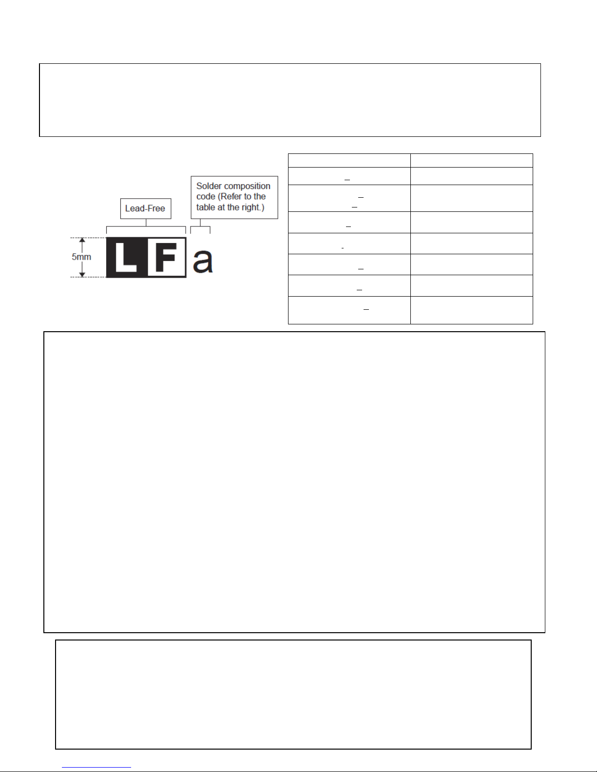
Solder composition
Solder composition code
LEAD-FREE SOLDER
The PWB’s of this model employs lead-free solder. The “LF” marks indicated on the PWB’s and the Service Manual mean “Lead-Free” solder.
The alphabet following the LF mark shows the kind of lead-free solder.
<Solder composition code of lead-free solder>
Sn-Ag-Cu
Sn-Ag-Bi
Sn-Ag-Bi-Cu
Sn-Zn-Bi z
Sn-In-Ag-Bi i
a
b
Sn-Cu-Ni n
Sn-Ag-Sb s
Bi-Sn-Ag-P
Bi-Sn-Ag
p
(1) NOTE FOR THE USE OF LEAD-FREE SOLDER THREAD
When repairing a lead-free solder PWB, use lead-free solder thread. Never use conventional lead solder thread, which may cause a
breakdown or an accident.
Since the melting point of lead-free solder thread is about 40°C higher than that of conventional lead solder thread, t he use of the exclusive-use soldering iron is recommendable.
(2) NOTE FOR SOLDERING WORK
Since the melting point of lead-free solder is about 220°C, which is about 40°C hi gher than that of conventional l ead solder, and its soldering
capacity is inferior to conventional one, it is apt to keep the soldering iron in contact with the PWB for longer time. This may cause land
separation or may exceed the heat-resistive temperature of components. Use enough care to separate the soldering iron from the PWB when
completion of soldering is confirmed.
Since lead-free solder includes a greater quantity of tin, the iron tip may corrode easily. Turn ON/OFF the soldering iron power frequently.
If different-kind solder remains on the soldering iron tip, it is melted together with lead-free solder. To avoid this, clean the sol dering iron tip
after completion of soldering work.
If the soldering iron tip is discolored black during soldering work, clean and file the tip with steel wool or a fine filer.
THERE IS A RISK OF EXPLOSION IF THE BATTERY
IS REPLACED BY AN INCORRECT TYPE.
PROPERLY DISPOSE OF USED BATTERIES ACCORDING
CAUTIONS
TO THE INSTRUCTIONS.
Page 3
CHAPTER 1. SPECIFICATIONS
(Including the drawer)
Power
AC adapter
Operating: 8.1W
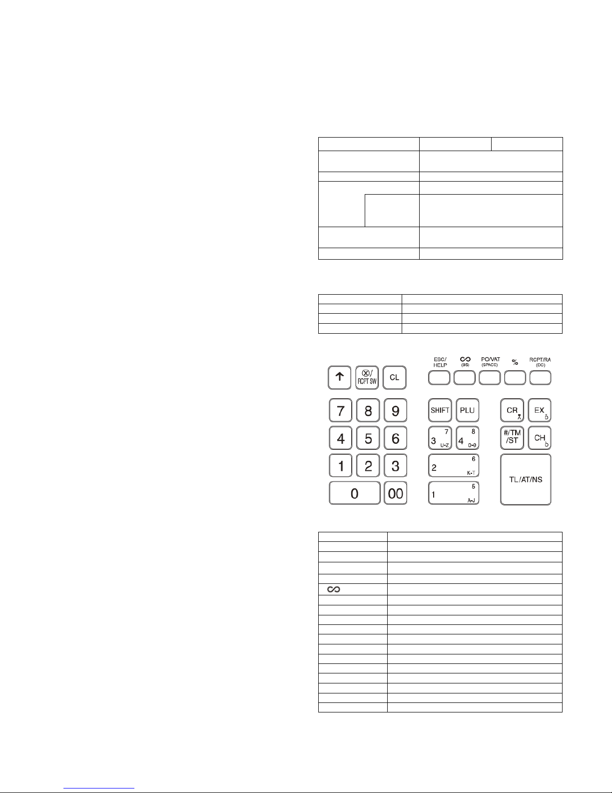
Type
Normal keyboard
Key position
STD / MAX 30
Key Pit ch
19 (W) x 19 (H) mm
Key layout
Fixed type
0-9, 00
Numeric keys
Paper feed key
Multiplication / Receipt switch key
CL
Clear key
(BS)
ESC/ HELP
Escape / help key
%
Percent key
PO/VAT (Space)
Paid out / VAT key
PCPT / RA (DC)
Receipt / Received on account key
SHIFT
Department shift key
PLU
PLU (Price Look Up) key
CR
Credit key
EX
Exchange Key
CH
Check key
#/TM/ST
Non add / Time / Subtotal
TL/AT/NS
Total / Amount tendered / No sale key
1. PRODUCTS OUTLINE
The XE-A107, A137 and A147 are developed in accordance with
following basic concepts.
1) The XE-A137 and XE-A147 are a mass-route popular class
ECR and low-class European Fiscal model.
2) Main features of XE-A137 and XE-A147 are 1-sheet drop-in
thermal printer, and SD card slot.
3) XE-A147 also has features of RS-232 port and battery option.
2. MAIN FEATURE & FUNTTION
1) New design
2) Color variation (Black and white)
3) 1-Sheet drop-in thermal printer (XE-A137/XE-A147)
- Print speed: Approx. 7 lines/Sec.
- Paper width: 58mm
4) SD-card slot standard: for Programming and data export
(XE-A137/XE-A147)
5) PC link (Programming tool) (XE-A137/XE-A147)
6) Local language support (XE-A137/XE-A147)
7) RS232C port(D-sub) standard: for FISCAL control box
connection (XE-A147 only)
8) Battery option is available (XE-A147 only)
[1] XE-A137 / XE-A147
1. BASIC SPECIFICATIONS
XE-A137-BK/WH XE-A147-BK/WH
External dimension
Weight
source
Power consumption
Working temperature
Europe/
Asia/ME/
Oceania etc
335(W) x 360 (D) x 190 (H) mm
Approx 5kg
AC220-230V (50/60Hz)
AC230- 240V (50Hz)
Stand-by: 1.9W
0~40°C (32 to 104°F)
2. KEYBOARD
1) KEYBOARD OUTLINE
2) KEYBOARD LAYOUT
3) KEY LIST
Key top Description
↑
X
○
/RCT SW
DEPT 1-4 (5-8) Department 1-4 (5 -8) key
Void key
1-1
Page 4
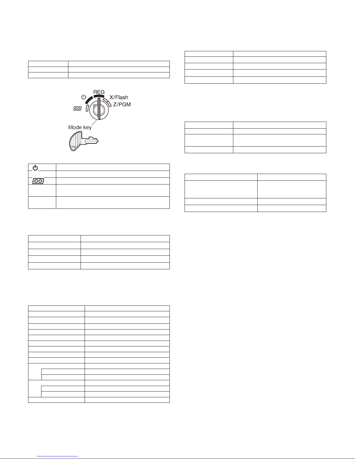
3. MODE SWITCH
Type
Rotary switch type with Mode key
STEP
5
Turns the display off. No operations are possible
REG
Permit transaction entry
flash reports
programming
Display device
LED numeric display
Number of line
1 line
Color of display
Yellow Green
Character size
Numeric: 14.2 (H) x 8.0 (W) mm
Printing digits
30 digits
Character size
1.25 mm(W) x 3.0 mm (H)
Printing speed
Approx. 7lines / Sec.
Validation printing
None
Logo stamp
None
Ink roller
None
Graphic Logo Print
Yes (Size: 360 mm(W) x 180 mm(H))
Paper end sensor
Receipt side
Yes
Paper near end sensor
Receipt side
None
Journal side
None
Paper type
Thermal paper
Paper roll diameter
66 to 72g/m2
Plastic
Bell
--
bottom
Separation from the drawer
Disallowed
compartments
Bill separator
-
Number of compartments
3B/6C (V model)
1) MODE SWITCH OUTLINE
2) LAYOUT
2) PAPER
Paper roll width 57.5 ±0.5mm
φ80mm
Paper Thickness
Paper weight
72 to 78μm
6. DRAWER
1) DRAWER BOX AND DRAWER
Material
3) FUNCTION
X/Flash
Z/PGM
Permit correction after final a transaction
Permits printing of sales reports and display the
Permits printing and resetting of sales reports and
4. DISPLAY
1) OPERATOR DISPLAY
Number of positions 9 digits numeric display (V model)
5. PRINTER
1) PRINTER
Printing system Thermal printer
Release lever
Drawer open sensor
Standard equipment: situated at the
--
2) MONEY CASE
Separation of the bill
compartments from the coin
Allowed
Cutter type Manual
Ink Ribbon None
Journal side None
Printer cover key None
1-2
Page 5
[2] XE-A107
(Including the drawer)
Weight
Approx 4.0kg
etc
AC220 - 230V (±10%)
Power consumption
Operating: 2.3W
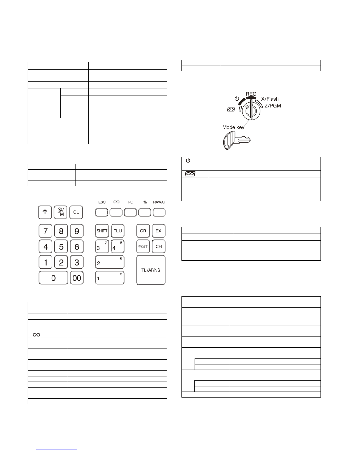
Type
Normal keyboard
Key position
STD / MAX 30
Key Pit ch
19 (W) x 19 (H) mm
Key top
Description
0-9, 00
Numeric keys
Paper feed key
Multiplication / Time key
CL
Clear key
ESC
Escape / help key
%
Percent key
PO
Paid out key
SHIFT
Department shift key
PLU
PLU (Price Look Up) key
DEPT 1-4 (5-8)
Department 1-4 (5 -8) key
EX
Exchange key
CH
Check key
#/ST
Non add / Subtotal
Type
Rotary switch type with Mode key
STEP
5
Turns the display off. No operations are possible
REG
Permit transaction entry
Permit correction after final a transaction
flash reports
programming
Display device
LED numeric display
Number of line
1 line
Color of display
Yellow Green
Character size
Numeric: 14.2 (H) x 8.0 (W) mm
Printing capacity
Max. 13 characters
Character size
1.6 mm(W) x 2.1 mm (H)
Printing speed
Approx. 1.4lines / Sec.
Validation printing
None
Logo stamp
None
Ink roller
None
Graphic Logo Print
None
Paper end sensor
Receipt side
None
Paper near end
Receipt side
None
Journal side
None
Printer cover key
None
1. BASIC SPECIFICATIONS
XE-A107-BK/WH
External dimension
Power
source
Europe/
Asia/ME/
Oceania
335(W) x 360 (D) x 190 (H) mm
AC adapter
Stand-by: 1.5W
3. MODE SWITCH
1) MODE SWUTCH OUTLINE
2) LAYOUT
Working temperature
0~40°C (32 to 104°F)
2. KEYBOARD
1) KEYBOARD OUTLINE
Key layout Fixed type
2) KEYBOARD LAYOUT
3) KEY LIST
3) FUNCTION
X/Flash
Z/PGM
Permits printing of sales reports and display the
Permits printing and resetting of sales reports and
4. DISPLAY
1) OPERATOR DISPLAY
Number of positions 9 digits numeric display (V model)
5. PRINTER
1) PRINTER
Printing system P rint wheel selective type
↑
X
○
/TM
Void key
RA/VAT Received on account / VAT key
CR Credit key
TL/AT/NS Total / Amount tendered / No sale key
Cutter type Manual
Ink Ribbon None
Journal side None
sensor
1-3
Page 6
2) PAPER
Paper type
Bond paper
Paper roll diameter
Paper weight
47 to 64g/m2
Plastic
Bell
--
bottom
Separation from the drawer
Disallowed
compartments
Bill separator
-
Power consumption
7.2V / 1265mh
Type
Nickel Metal Hydride (Ni-MH) battery
Re-chargeable
Paper roll width 57.5 ±0.5mm
φ80mm
Paper Thickness
0.06 to 0.085mm
6. DRAWER
1) DRAWER BOX AND DRAWER
Material
Release lever
Drawer open sensor
2) MONEY CASE
Separation of the bill
compartments from the coin
Number of compartments 3B/6C (Vmodel)
Standard equipment: situated at the
--
Allowed
[3] XE-A1BT
Installable model XE-A147 only
1-4
Page 7
CHAPTER 2. OPTIONS
Optional battery
Price
Fix angle A
(for tumble prevision)
Fix angle B
(for tumble prevision)
Price
5 Rolls / Pack
Ink roller
(For XE-A107)
5 Rolls / Pack
XE-A147)
Price
rank
RS232C loop back test tool
(For XE-A147)
1. OPTIONS
Product name Model Description
Optional battery XE-A1BT
(for XE-A147)
2. SERVICE OPTIONS
Parts code
LANGK7612BHZZ AF
LANGK7613BHZZ AN
XHBS730P06000 AC Screw (for set the fix angle)
rank
Description
3. SUPPLIES
Item Parts code
Roll paper DPAPR1025CSZZ AV
INK Roller NROLR1022RCZB AZ
Thermal
paper
*Handled as service par ts
TPAPR6656RC05 BA
rank
Description
(For XE-A107)
(For XE-A137 /
4. SPECIAL SERVICE TOOLS
Parts code
UKOG-2374RCZZ AV
Description
CHAPTER 3. MASTER RESET
Master reset:
Clears all the memory and initializes each preset parameter.
The master reset should be performed by using the following
procedure.
1. Turn off the power (Power OFF). (See Note 1))
2. Let the ECR be without the memory back up battery.
3. Turn the mode switch to the others of Power-off position.
4. Turn on the power (Power ON). (See Note 2))
When the master rest is completed, the buzzer sounds
intermittently three times.
5. Attach the memory back up battery to the ECR.
The master reset can also be accomplished in the foll owing
case. (See Note 3))
Note 1) Power OFF:
Means disconnecting the AC power supply to the
machine. (Specifically, unplugging the machine)
Note 2) Power ON:
Means connecting the AC power to the ma-chine.
(Specifically, plugging in the machine)
Note 3) In case a power failure occurs when the machine
has no battery installed, the master reset operation is
automatically performed after the power has been
restored.
2-1
Page 8
CHAPTER 4. HARDWARE DESCRIPTI O N & OPE RATIO N P RICIPLE
ME/Africa
1. OUTLINE
XE-A107 XE-A137,XE-A147
CPU
PRINTER 58mm Print wheel type 58mm Thermal Printer
Rolling up
SRAM None 1Mbit(128kByte x8)
ROM For Program MASK ROM in CPU FLASH ROM in CPU
DISPLAY 7segments LED
Display
digits
KEY Normal KEY: 30key
Mode S/W 5 steps rotary type
I/F
POWER SUPPLY AC adapter for XE-A107 AC adapter for XE-A137or XE-A147
BATTERY
DRAWER Standard: 1 unit
EU/Oceania/Asia/
EU/Oceania/Asia/
ME/Africa
USB None
SD None 1slot
DRAWER 1port (For Standard drawer only. There is no optional drawer port)
RS232 None 1port ( for XE-A147)
EFT None
MEMORY BACK UP LR6 (AA size)
OPTIONAL
OPERATION BATTERY
8bit MASK CPU
uPD780023AGC *4.19MHz
MASK ROM Built in (For Program)
Yes None
9 digits
None Option: XE-A1BT (XE-A147only)
32bit CPU
MB9AF116N *16MHz
FLASH ROM Built in (For Program)
4-1
Page 9
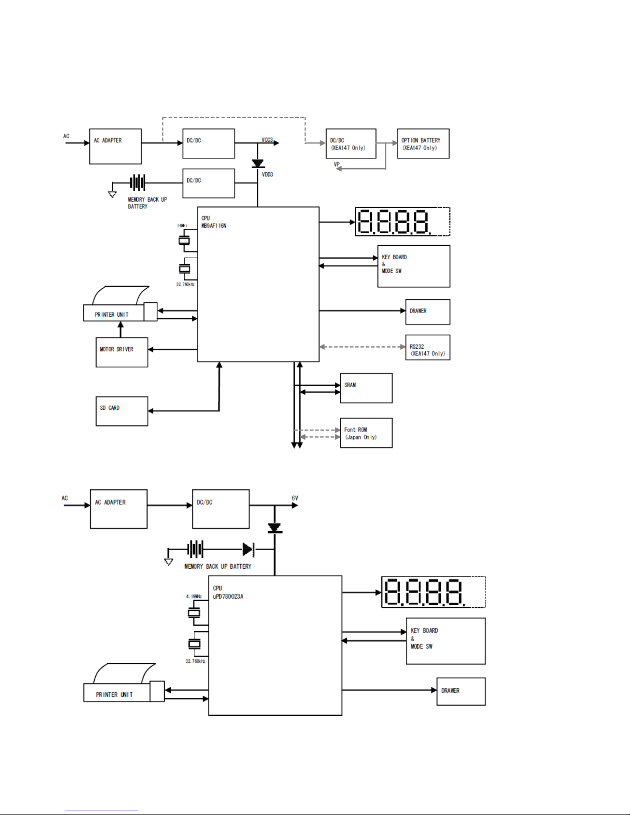
2. Block diagram
1) XE-A147 / XE-A137
2) XE-A107
4-2
Page 10

3. Description
Key top
Description
CL
Clear key
Void key
ESC
Escape / help key
%
Percent key
PO
Paid out key
PLU
PLU (Price Look Up) key
DEPT 1-4 (5-8)
Department 1-4 (5 -8) key
CR
Credit key
EX
Exchange key
TL/AT/NS
Total / Amount tendered / No sale key
1) DISPLAY
The display of these models is LED type. And there are 2 types
such as 8 digits and 9 digits. It is depend on the destination of
models.
a. Display content
Display
Departments/PLU Code:
The department code or PLU code entered appears on the left.
For example, if the key for department 1 is pressed, "1" would
appear in the extreme left position.
Repeat:
Indicates the number of times the same department key is
pressed. If an entry is repeated more than ten times, only the
first digit is displayed (12 displays as "2").
( ) Low battery:
This symbol appears when the power of the installed batteries is
below a certain level or you need to replace the batteries with
new ones. (see the "Maintenance" section for explanation.)
) No battery:
(
This symbol appears when no batteries are installed,
installed batteries are empty.
In addition, the following appear when appropriate:
The minus sign (-) can appear in positions 2 to 8.
The decimal point appears in positions 1 to 3.
When entry of the secret code is necessary, "---" appears in
positions 1 to 4.
or the
2) KEYBOARD AND MODE SW
a. Keyboard layout (ex XE-A107)
( ) Error:
This symbol appears, accompanied by a warning beep, when an
error is made. If this occurs during a transaction because of an
excessive digit entry, simply press [CL] and re-enter correctly.
( ) Program:
This symbol Appears on the display when the cash register is
being programmed in the Z/PGM mode.
( ) Finalization:
This symbol appears when a transaction is finalized by pressing
[CA/ AT/NS], [CH] or [CHK].
( ) Subtotal:
This symbol appears when [#/SBTL] is pressed and the cash
register computes the subtotal, and also when the amount
tendered is less than the total sale amount.
( ) Change:
This symbol appears whenever the change due amount is
displayed.
( ) Exchange:
This symbol appears
in foreign currency
when [EX] i s pressed to c alculate a s ubtotal
b. Key list
0-9, 00 Numeric keys
↑
X
○
/TM
RA/VAT Received on account / VAT key
SHIFT Department shift key
CH Check key
#/ST Non add / Subtotal
Paper feed key
Multiplication / Time key
4-3
Page 11

Mode switch layout
Permit correction after final a transaction
X/Flash
flash reports
Z/PGM
programming
c. Function
REG
Turns the display off. No operations are possible
Permit transaction entry
Permits printing of sales reports and display the
Permits printing and resetting of sales reports and
3) BATTERY
a. MEMORY BACK UP BATTERY
For memory back up, the dry battery ULM-3 (3 pieces) are
needed.
1. Memory holding time:
Approx. 1 year after New dry batteries are installed.
(It is depend on the battery capacity)
2. Battery exchange method:
When the low battery symbol "L" lights up, replace the
batteries (3 AA) replaced by the following method;
1) Power on t he ECR.
2) Mode switch turn to "REG" mode.
3) Remov e the OLD dry batteries (3 pieces).
4) The no-battery symbol "
5) Insert the NEW dry batteries (3 pieces).
6) Confirm the low battery symbol "L" and no-battery
symbol "
L" is off .
L" light up.
b. LOW BATTERY
c. NO BATTERY
If the user forgets to replace the battery and the battery voltage
falls below a certain level, or if a power failure occurs with no
batteries installed, the memory contents cannot be retained. The
CPU judges it as no battery and performs the master reset. In this
case, all the settings and registrations are cleared. If, however, the
power is continuously supplied to the AC cord, the memory
contents are retained.
Low battery: Batteries are installed, but the voltage is
No battery: Batteries are not installed or the voltage is extremely
Low battery & No battery indication will appear at the most left
position of display when the battery voltage is low.
CASE 1: When any numeric entry & item entry is not done or
CASE 2: When numeri c ent ry or item entry is done.
low. Memory back up can be done.
low. The master reset is executed when a power
failure occurs, when the batteries are not properly
changed.
just after
finalization.
The machine can indicate the battery condition. (Always)
Battery condition is not appeared.
Exceptionally, at the power is restored after power failure,
the low battery & No battery indication will appear on the
display only when the battery voltage is low.
And the indication will disappear after any key entry.
[Display sample]
" 0.00" : Battery is OK.
"L 0.00" : Low battery
L 0.00" : No battery
"
After finalization
"F 12.34": Battery is OK.
"L 12.34": Low battery ("L" indicate instead of "F".)
L 12.34": No battery ("L" indicate instead of "F"
"
Low battery indication will appear on the left side of display when
the battery voltage is low.
CASE 1: When sitting idle or after completion of transaction. The
CASE 2: Low battery indication will not appear during key
machine can indicate the low battery condition (Always)
operations, but will appear after power up of the cash
register.
[Display sample]
“0.00”: Battery is OK.
"L 0.00": Low battery (The batteries have to be replaced.)
After finalization
"F 12.34": Battery is OK.
"L 12.34": Low battery ("L" indicate instead of "F".)
4-4
Page 12

CHAPTER 5. DIAGNOSTICS
4
Drawer test
8
CLOCK test
characters
position
version
[Z/PGM]
1. XE-A137/XE-A147
1) Diagnostic menu
DIAG menu DESCRIPTION
1 Mode switch test
2 Key test
3 Display test
5 Printer test
6 Printer paper sensor test
7 AD conversion level test
Destination display /
9
ROM version
10 SD card test
11 RS232C (XE-A147 only)
12 ROM (Japan only)
13 RAM
To check the mode key function
Keyboard check
To check a display
To check a drawer opening
Printer test
To check a printer paper sensor
AD conversion check
To check the clock on CPU
To check the Destination setting and
ROM version
To check the SD-card write protection
To execute the loopback test
To check the ROM for Japanese
To execute the RAM read write test
2) Entering procedure
It is possible to enter the DIAG mode with following procedure;
1. To set the mode switch to Z/PGM position
2. To input the job code in accordance with below list
3. To push the PO key
4. Start the Diagnostic mode
DIAG menu
Mode switch test
Key test
Display test
Drawer test
Printer test
Printer Paper sensor test
AD conversion level test
CLOCK test
Destination display / ROM
SD card test
RS232C (XE-A147 only)
ROM check (Japan only)
RAM check
Mode key
Z/PGM ‘1’ + PO key
Z/PGM
Z/PGM
Z/PGM
Z/PGM
Z/PGM
Z/PGM
Z/PGM
Z/PGM
Z/PGM
Z/PGM
Z/PGM
Z/PGM
Key code
‘2’ + PO ke y
‘3’ + PO ke y
‘4’ + PO ke y
‘5’ + PO ke y
‘6’ + PO ke y
‘7’ + PO ke y
‘8’ + PO ke y
‘9’ + PO ke y
‘10’ + PO key
‘11’ + PO key
‘12’ + PO key
‘13’ + PO key
3) Description
3-1) MODE KEY SWITCH
a. Test Procedure
Change over the mode switch as follows. If the mode switch data
in the proper sequence is not read with the above operat ion, an
error is printed.
To cancel this test mode, set the mode switch to any a position
other than [Z/PGM] to [Z/PGM]. In this case, the completion print is
performed.
During the test, the display indicates hard codes which correspond
to the switch position.
The mode switch is set to the “OFF position”, it will no-display.
<Note>
In the test, the mode key should be fixed over 1second in each
position.
b. Mode switch operation
MODE: [Z/PGM] → [X/FLASH] → [REG] → [OFF] → [VOID]
c. Display
5-1
Page 13

d. Test result print
[TL] key pushed
When a test results is OK, following result is printed out
M ODE KEY SWITCH OK
When a test result is NG, following result is oriented out.
MODE KEY SWITCH NG
3-2) KEY TEST
a. Test Procedure
Perform the keyboard check with the sum check data of the key
code.
Enter the any key other than [TL] key, and then enter the [TL] key,
finally. In the process above, machine records the sum, and after
[TL] key entered, compare with check sum proper check sum.
It is possible to re-operate from the beginning, enter the [CL] key 3
times, when operation is wrong.
b. Display
Entered key code:
(According to entering)
Original check sum:
1761(4 digits)
c. Test result print
When a test results is OK, following result is printed out
KEY XXXX-YYYY - OK
When a test result is NG, following result is printed out.
KEY XXXX-YYYY - NG
3-3) DISPLAY TEST
a. Test Procedure
Check the continuous buzzer sound and the display state.
<Check points>
1. The all segments are lighted up correctly.
2. The brightness of all segments is same level.
1. Segments display test
The following pattern is displayed. When [TL ] key pushed,
the display pattern is changed to next.
< Display >
[TL] key pushed
[TL] key pushed
[TL] key pushed
[TL] key pushed
[TL] key pushed
5-2
Page 14

2. Shift display test
The following pattern is displayed. When [TL] key pushed,
the display pattern is changed to next.
Finally, all segments are lighted on.
< Display >
[TL] key pushed
[TL] key pushed
[TL] key pushed
[TL] key pushed
[TL] key pushed
[TL] key pushed
[TL] key pushed
[TL] key pushed
[TL] key pushed
3. Completion of test
When [TL] key pushed after above test, the test is finished
as OK status.
When other than [TL] key pushed after above test , the test
is finished as NG status.
b. Test result print
When a test results is OK, following result is printed out
DISPLAY&BUZZER OK
When a test result is NG, following result is printed out.
DISPLAY&BUZZER NG
3-4) DRAWER TEST
a. Test Procedure
The drawer opens with the above key operation. Check that the
drawer is open.
After drawer open, check the drawer opening,
When drawer open correctly, push the [TL] key, test will finish with
OK status.
If not, push other than [TL] key, test will finish with NG status.
b. Test result print
When a test results is OK, following result is printed out
DRAWER OK
When a test result is NG, following result is printed out.
DRAWER NG
3-5) PRINTER TEST
a. Test Procedure
With the above key operation, the print test pattern is printed as
below.
Check the print result s.
When print result is OK, push the [TL] key, test will finish with OK
status.
If not, push other than [TL] key, test will finish with NG status.
/////////// ------- ///////////
/////////// ------- ///////////
/////////// ------- ///////////
//////////////////////////////////////////////
//////////////////////////////////////////////
All “/” 6 lines
5-3
Page 15

b. Test result print
1
BBA TTERY V OLT AGE
Back up battery voltage
2
HEAD TEMP
Head temperature
(XE-A147 only)
(XE-A147 only)
< BBA TTERY V OLT AGE >
< HEAD VO LT A GE >
< BA TTERY VOLTAGE > (for XE-A147 only)
< BATTERY TEMP > (for XE-A147 only)
When a test results is OK, following result is printed out
PRINT ER OK
When a test result is NG, following result is printed out.
PRINT ER NG
3-6) PRINTER PAPER SENSOR TEST
a. Test Procedure
With the above key operation, the sensor test is started.
The status of printer paper sensor is displayed by real time.
When [TL] key pushed, the status of printer paper sensor is
printed out then the test is finished.
b. Display
<Printer Paper is detected>
<Printer Paper is not detected>
c. Test result print
When print printer paper is being detected.
SENSO R PAPER YES
When print printer paper is being detected.
SENSO R PAPER NO
3-7) AD CONVERSION TEST
a. Test Procedure
With the above key operation, the AD conversion level is started.
The AD conversion reading data is displayed by real time.
The displaying is done by following sequence:
3 HEAD V OLTAGE Head voltage
4 BATTERY V OLTAG E Option Battery voltage
5 BA T TERY TEMP Option Battery temperature
When [TL] key pushed, the status of following data is printed out
then the test is finished.
b. Display
< HEAD TEMP >
5-4
Page 16

c. Test result print
Display
Hour
Minute
Second
Blink each 500msec
ROM ver
Destination
code
When the test completion, following result is printed out
< XE-A147 >
A/D
1 HEAD VOLTAGE X.XXV
2 HEAD TEMP X.XXV
3 BBATTERY VOLTAGE X.XXV
4 BATTERY VOLTAGE X.XXV
5 BATTERY TEMP X.XXV
<XE-A137>
A/D
1 HEAD VOLTAGE X.XXV
2 HEAD TEMP X.XXV
3 BBATTERY VOLTAGE X.XXV
3-8) CLOCK TEST
a. Test Procedure
With the above key operation, the clock test is starte d.
The clock data is read from CPU and displayed by real time.
If count up is done c orrectly, the result is OK, push the [ TL] key,
test will finish with OK status.
If not, push other than [TL] key, test will finish with NG status.
b. Display
c. Test result print
When a test result is OK, following result is printed out
CLO CK OK
When a test result is NG, following result is printed out
CLO CK NG
3-9) Destination display / ROM version check
a. Test Procedure
With the above key operation, the Destination display / ROM
version check is started.
The CPU version and destination setting are read from CPU then
displayed. The destination code is as follows;
North America EU Japan
0 1 2
Print
U V J
If the displayed destination is correct, the result is OK, push the
[TL] key, test will finish with OK status.
If not, push other than [TL] key, test will finish with NG status.
* In case of check sum is not correct, even if [TL] key is pushed,
but, it may judged “NG”. Because of OK/NG is automatically
judged by the program.
b. Display
<North America>
<EU>
<Japan>
c. Test result print
When a test result is OK, following result is printed out
DESTINATION U OK
ROM ver. 1.00
When a test result is NG, following result is printed out
DESTINATION U OK
ROM ver. 1.00
5-5
Page 17

3-10) SD card TEST
Output
Input
DTRn
RTSn
DSRn
DCDn
CTSn
NO.
CONTENTS
3-11) RS232C LOOP BACK TEST (XEA147 only)
a. Test Procedure
With the above key operation, the SD-card test is started.
The status of SD card is displayed by real time.
When [TL] key is pushed, the test is completion.
CD: Card detected.
WP: Write protection
b. Display
<CD: No / WP: No >
<CD: No / WP: Yes >
<CD: Y es / WP: No>
<CD: Y es / WP: Yes>
c. Test result print
<CD: No / WP: No >
SD CARD
CD: NO , WP: NO
<CD: No / WP: Yes >
SD CARD
CD : NO , WP: YES
<CD: Y es / WP : No>
SD CARD
CD: Y ES , WP: NO
<CD: Yes / WP: Yes>
SD CARD
CD : YES , WP: YES
a. Test Procedure
Before turn the power on, connect the loopback test jig:
UKOG-6646RCZZ to RS232C port. And turn the power on then
set to [Z/PGM] mode then push [1] [1] and [PO] key, the RS232C
loop back test is started.
When stat the test mode, the machine checks the reading of input
control signal, at first.
< The control signal check >
The read check is that DTR and RTS changed in accordance with
following pattern then check the logic of DSR, DCD and CTS. In
this time, if the checked logic is same as following list, the test
result is OK. If not, it is displayed ‘ERROR’.
<Control signal check>
OFF OFF OFF OFF OFF
OFF ON OFF ON ON
ON OFF ON OFF OFF
ON ON ON ON ON
< Data transfer check >
As a check data, the 256 bytes (from 00H to 0FFH) loop back
transfer is done. In this time the BAUDRATE setting is 38.4kbps.
< Completion of test mode >
Push the [TL] key, the test is finished then test result is printed out.
b. Test result print
When a test result is OK, following result is printed out
RS232C OK
When a test result is NG, following result is printed out
RS232C NG---ERROR NO.XXX
1 DTR-DSR
2 RTS-DCD
3 RTS-CTS
4 SD-RD(DATA)
3-12) ROM check (Japan only)
This test mode is not available without Japan model.
5-6
Page 18

3-13) RAM Check
a. Test Procedure
With the above key operation, the RAM check is st a r t e d.
At first, the address touch on address lines in all RAM area is
checked.
<For example the address touch test in all RAM area>
To check the following address
0x61000000、0x61000001、0x61000002、0x61000004
0x61000008、0x61000010、0x61000020、0x61000040
0x61000080、0x61000100、0x61000200、0x61000400
0x61000800、0x61001000、0x61002000、0x61004000
0x61008000、0x61010000、0x61020000
To write ‘55h’ to 0x61000000
To write ‘AAh’ to other than 0x61000000
To check the data in 0x61000000, if 55h is written, the result is
OK. If not, result is NG.
To c heck the data in the other than 0x61000000, if ‘AAh’ is
written, the results is OK, if not, result is NG
To write ‘55h’ to 0x61000001
To write ‘AAh’ to other than 0x61000001
To check the data in 0x61000001, if 55h is written, the result is
OK. If not, result is NG.
To c heck the data in the other than 0x61000001, if ‘AAh’ is
written, the results is OK, if not, result is NG
To write ‘55h’ to 0x61020000
To write ‘AAh’ to other than 0x61020000
To check the data in 0x61020000, if 55h is written, the result is
OK. If not, result is NG.
To c heck the data in the other than 0x61020000, if ‘AAh’ is
written, the results is OK, if not, result is NG
Secondly, the write & verify test is executed.
The different writing data are written in to each address.
<For example>
Address Written data
0x6100_0000~0x6101_FFFF 00h write & verify
0x6100_0000~0x6101_FFFF FFh write & verify
0x6100_0000~0x6101_FFFF 55h write & verify
0x6100_0000~0x6101_FFFF AAh write & verify
The test result is displayed and printed out then test is finished
when the [TL] key pushed.
b. Test result print
When a test result is OK, following result is printed out
RAM CHECK OK
When a test result is NG, following result is printed out
RAM CHECK NG
5-7
Page 19

2. XE-A107
8
CLOCK test
Mode key
[Z/PGM]
[X/FLASH]
[REG]
[OFF]
[VOID]
1) Diagnostic menu
DIAG MENU DESCRIPTION
1 Mode switch test
2 Key test
3 Display test
4 Drawer test
5 Printer test
6 CPU ver. display
7 Battery level test
9 Destination display
To check the mode key function
Keyboard check
To check a display and buzzer
To check a drawer opening
Printer test
CPU version check
Battery condition check
To check the clock on CPU
To check the Destination setting
2) Entering procedure
It is possible to enter the DIAG mode with following procedure;
1. To set the mode switch to Z/PGM position
2. To input the job code in accordance with below list
3. To push the PO key
4. Start the Diagnostic mode
DIAG menu
Mode switch test
Key test
Display test
Drawer test
Printer test
CPU ver. display
Battery level test
CLOCK test
Destination display
position
Z/PGM ‘1’ + PO ke y
Z/PGM
Z/PGM
Z/PGM
Z/PGM
Z/PGM
Z/PGM
Z/PGM
Z/PGM
Key code
‘xxxx2’ + PO key
‘3’ + PO ke y
‘4’ + PO ke y
‘5’ + PO ke y
‘6’ + PO ke y
‘7’ + PO ke y
‘8’ + PO key
‘9’ + PO ke y
3) Description
3-1) MODE KEY SWITCH
a. Test Procedure
Change over the mode switch as follows. If the mode switch data
in the proper sequence is not read with the above operat ion, an
error is printed.
To cancel this test mode, set the mode switch to any a position
other than Z/PGM to Z/P GM. In this case, the completion print is
performed.
During the test, the display indicates hard codes which correspond
to the switch position.
The mode switch is set to the “OFF position”, it will no-display.
<Note>
In the test, the mode key should be fixed over 1second in each
position.
b. Mode switch operation
MODE: [Z/PGM] → [X/FLASH] → [REG] → [OFF] → [VOID]
c. Display
d. Test result print
When a test results is OK, following result is printed out
When a test result is NG, following result is printed out.
01
----01
5-8
Page 20

3-2) KEY TEST
CHECK SUM
a. Test Procedure
Perform the keyboard check with the sum check data of the key
code.
Enter the sum check data of each model in the four digits
preceding the DIAG number 02, and compare the data with the
key position code which is added until the [TL] key is pushed.
If the data coincides with the code, the completion print is
performed.
If not, the error print is performed
<Note>
The check sum above should be higher 0100.
0001 to 0099 check sum does not reflect.
b. Display
4 digits
c. Test result print
When a test results is OK, following result is printed out
02
When a test result is NG, following result is oriented out.
----02
3-3) DISPLAY TEST
a. Test Procedure
Check the display state.
1. The decimal point will shi ft from the lower digit to the upper,
step by step (500msec).
2. The all segments light up
In this time, the buzzer sound will stop. But the segments
are all lights up until any key pushed.
3. To cancel the test mode, press any k ey, after that the test
result is printed.
<Check points>
1. The all segments are lighted up correctly.
2. The brightness of all segments is same level.
b. Display
c. Test result print
When pushed any key, the test mode is cancelled, and the
completion print is performed.
03
3-4) DRAWER TEST
a. Test Procedure
The drawer opens with the above key operation. Check that the
drawer is open. After drawer open, the test will finish automatically
and print the following report.
b. Test result print
04
3-5) PRINTER TEST
a. Test Procedure
With the above key operation, the print test pattern is repeatedly
printed as below.
Pushing any key will terminate the test after the completion of one
cycle print. (The receipt is issued until any key pushed.)
<Check points>
1. There is no lack character.
2. There is no unclear character.
b. TEST Pattern
<U model> <V model>
€・- 98765432X
0123456789 -CG
000X
111Z
222RA
333PO
444VD
555%
666@
777ST
888TX
999CA
---CH
・・・CK
€ € € CG
000X
111Z
222RA
333PO
444VD
555%
666@
777ST
888TX
999CA
---CH
・・・CK
###CG
#・- 98765432X
0123456789 -CG
5-9
Page 21

3-6) CPU version PRINT
0155 or greater
Normal
0138 or smaller
No battery display
North Americ a
EU
Japan
Display 0 1
2
Hour
Minute
Second
Blinking per 0.5sec
3-9) DESTINATION DISPLAY
a. Test Procedure
The CPU version is pri nted wit h above key operation.
This mode is finished automatically when print completed.
b. Test result print
(When Version 1.00)
← CPU Version No.
← 06
3-7) MEMORY BATTERY VOL T AGE SENSOR TEST
a. Test Procedure
Displays A/D conversion port read value of memory battery.
To terminate the test, press any key.
<The displayed value and status>
0154 or smaller Low battery display
b. Test result print
3-8) TIME DISPLAY T EST
a. Test Procedure
Displays time of CPU with above key operation.
<Check point>
1. To blink the “-“ (hyphen)
2. To count up the clock
To terminate the test, press any key.
b. Display
c. Test result print
yymmdd-hhmmss
0100
06
(MRS is done when power on)
07
08
a. Test Procedure
The following destination code in the firmware is dis played with
above key operation.
To terminate the test, press any key.
b. Display
c. Test result print
09
5-10
Page 22

CHAPTER 6. OTHERS
[1] Installing the Fixing Angle Bracket
To prevent the register from moving when the drawer opens, the
fixing angle bracket is provided with option. By attaching the
bracket to the table where the register is installed, it is possible to
hook the register on this bracket and secure the register to its
position.
a. How to install the fixing angle bracket
1) To fix the fix angle-A (LANGK7612BHZZ) by the Screw
(XHBS730P06000) to the bottom of the resister.
2) Thoroughly clean the location where the fixing angle-B
(LANGK7613BHZZ) is to be placed.
3) Peel off the adhesive tape on the fixing angle bracket.
4) Hook the angle bracket onto the fix angle-A which is located
at the bottom rear of the register.
5) Firmly stick the fixing angle B to the table surface that
cleaned above.
b. How to remove the register from the fixing angle bracket
1) Lift up the front of the register and pull the register towards
you.
[2] Printer for XE-A137/A147 series
Since there are no service parts for this model printer, only the
printer unit is supplied. Therefore, the printer component parts are
not supplied and no service document is issued.
For troubleshooting of the printer, refer to the below:
a. Thermal Printer Troub leshooting
a. Loading and removing the journal paper
Procedure for loading and removing the journal paper
1) Journal paper loading procedure:
Please release the platen unit before loading the journal
paper.
When loading the journal paper, please set the paper
straight with the leading edge of the paper 5cm or longer
sticking out from the top face of the printer mechanism.
2) Journal paper removal procedure:
Please release the platen unit before removing the journal
paper.
3) Paper removal procedure at the time of the paper jam
Please take off the jammed paper in accordance with the
Journal paper removal procedure.
Notes for loading and removing journal paper
Please release the platen unit before loading the journal
paper. The jour nal paper cannot be loaded by the auto
loading function on this product.
When loading the journal paper, please set the paper
straight with the leading edge of the paper 5cm or longer
sticking out from the top face of the printer mechanism.
When installing the platen unit, the platen unit drive gear
contacts with the deceleration gear, and in some cases,
the platen unit cannot be installed. In this case, please
release the platen unit, and then try to install it again.
When the journal paper is skewed, please keep feeding
the paper until the paper is straightened or reload the
journal paper.
When taking off the journal paper due the paper jam,
please release the platen unit first. Please do not forcibly
pull out the jammed paper otherwise it may cause the
damage.
b. Cleaning of the thermal head
If the surface of the thermal head gets dirty for some reasons,
please clean the thermal head, otherwis e it may lead to the print
error etc.
Cleaning procedure of the thermal head
Please be sure to shut OFF the power before cleaning the
thermal head.
Please release the platen unit.
When cleaning the thermal head, please wipe out the
contamination on the heating element section using the
cotton swab moistened with the ethyl alcohol or the isopropyl alcohol.
After the alcohol is completely volatilize, please install the
platen unit.
Notes for the thermal head cleaning
Right after the printout, the thermal head and its sur-
roundings reach the high temperature so please be sure
not to clean the thermal head right after the printout.
When cleaning the thermal head, please release the pla-
ten unit.
Please be sure not to clean the thermal head with the tool
which may damage the heating element such as the sand
paper and the cutter etc.
6-1
Page 23

[2] Printer for XE-A107 series
nected
mode switch to "REG" and press "CL" key)
down
Paper thickness: 0.06~0.085mm
Since there are no service parts for this model printer, only the
printer unit is supplied. Therefore, the printer component parts are
not supplied and no service document is issued.
For troubleshooting of the printer, refer to the table below:
b. Trouble shooting
Phenomena Check point/possible cause Repair
The printer motor is locked and the buzzer
sounds intermittently
The printer does not work properly
Defective print (Lack on the upper/ lower or
left/right side)
Thin print Check if the ink roll life is reached Replace the ink roll.
Uneven pitch of print paper feed Check if the roll paper size is proper Use roll paper as specified below;
Check if the printer cable is discon-
Check if the printer life is reached Replac e the printer
Check if any foreign material is attached
to the printing type wheel or the gear
section
Check if the printing type is worn down Replace the printer.
Check if any foreign material is attached
to the printing type wheel
Check if the printing type wheel is worn
down
Check if the ink roll is properly installed Install the ink roll properly
Check if the printing type wheel is worn
Check and repair the printer cable
Remove the foreign material.
(After removing the foreign material, set the
Install the ink roll properly
Replace the printer
Replace the printer
Paper width: 57.5 0.5mm
Outside diameter: ϕ80mm or less
Inside diameter of paper tube: ϕ12mm or less
Check if a load is applied to the roll paper during paper feeding. This may result from a foreign materials attached to
the roll paper.
Remove any foreign material.
6-2
Page 24

CHAPTER 7. ERROR CODE
Error
E01
Registration error
Make a correct key entry.
E02
Miss operation error
Make a correct key entry.
E11
Compulsory depression of the [#/TM/ST] key
Press the [#/TM/ST] key and continue the operation
E12
Compulsory tendering
Make a tendering operation.
E34
Overflow limitation error
Make a registration within a limit of entry
E35
The open price entry is inhibited
Make a preset price entry.
E37
The direct finalization is inhibited
Make a tendering operation.
E67
Subtotal void is not allowed.
E80
The battery trouble is occurred
Change the battery
When the following error codes are displayed, press the [CL] key and take a proper action according to the table below.
code
Error status Action
E33
E36 The preset price entry is inhibited Make an open price entry
Compulsory SCM (starting cash memory) entry
Make the SCM (starting cash memory) entry.
Finalize the transaction, and correct the wrong entries in the mode.
7-1
Page 25

8-1
CHPTER 8. PARTS LIST
NO. PARTS CO DE
PRICE
RANK
NEW
MARK
DESCRIPTION
1 0RDS1PSA19502 AR
N MODE SWITCH ASSY 107
0RDS1PSA19512 AR N MODE SWITCH ASSY 137/147
2 0RDS1PSA19501 BB N KEY UNIT ASSY 107
0RDS1PSA19529 BB N KEY UNIT ASSY 137/147
3 0RDS1PSA19532 BM N MONEY CASE UNIT (EA-BK)
0RDS1PSA19533 BM N MONEY CASE UNIT (EA-WH)
4 0RDS1PSA19462 AN N PRINTER COVER ASSY 107B
0RDS1PSA19541 BC N PRINTER COVER ASSY 107W
0RDS1PSA19544 BC N PRINTER COVER ASSY 147B
0RDS1PSA19545 BC N PRINTER COVER ASSY 137B
0RDS1PSA19546 BC N PRINTER COVER ASSY 147W
0RDS1PSA19547 BC N PRINTER COVER ASSY 137W
5 0RDS1PSA19549 BF N TOP CAB UNIT (A107 E-B)
0RDS1PSA19550 BF N TOP CAB UNIT (A107 E-W)
0RDS1PSA19551 BG N TOP CAB UNIT (A137 E-B)
0RDS1PSA19552 BG N TOP CAB UNIT (A137 E-W)
0RDS1PSA19553 BG N TOP CAB UNIT (A147 E-B)
0RDS1PSA19554 BG N TOP CAB UNIT (A147 E-W)
6 0RDS1PSA19563 BP N ASSY DRAWER SERVICE (A107B)
0RDS1PSA19566 BP N ASSY DRAWER SERVICE (A107W)
0RDS1PSA19568 BP N ASSY DRAWER SERVICE (A137B / A147B)
0RDS1PSA19570 BP N ASSY DRAWER SERVICE (A137W / A147W)
7
0RDDDCASST003
BC N
AC ADAPTOR 107B4
0RDDDCASST004 BC N
AC ADAPTOR 1
07B6
0RDDDCASST005 BC N
AC ADAPTOR 1
07B7
0RDDDCASST006 BC N
AC ADAPTOR 1
07B8
0RDDDCASST009 BC N
AC ADAPTOR 1
37B4
0RDDDCASST010 BC N
AC ADAPTOR 1
37B6
0RDDDCASST011 BC N
AC ADAPTOR 1
47B7
8 0RDS1PSA19467 BG N MAIN PCB ASSY 107
0RDS1PSA19485 BS N MAIN PCB ASSY 147
0RDS1PSA19513 BR N MAIN PCB ASSY 137
9 0RDS1PSA19475 AF N PRINTER PCB ASSY 107
NOTE
0RDS1PSA19491 AP N
PRINTER PCB ASSY 1
37/147
10 0RDS1PSA19477 AR N DC JACK PCB ASSY 107
0RDS1PSA19495 AV N
DC JACK PCB ASSY 1
37/147
11 0RDS1PSA19473 AW N 7SEG PCB ASSY 107
0RDS1PSA19497 AX N
7SEG PCB ASSY 1
37/147
12 0RDS1PSA19499 AL N Battery PCB ASSY (147)
13
0RDS00EEF0020
AB N E RING (PHAI2)
14
0RDS0GCJB9050
AC N SCREW B-TIGHT
15
0RDS1PM336259
AE N LOCK LEVER
16
0RDS1PM336264
AC N MONEY CASE ROLLER
17
0RDS1PM424072
AC N SCREW M3X8 P-TIG HT F
18
0RDS1PM429041
AC N 2.6X4 B-TIG HT FL A T H
19
0RD1QB200AJ0B
AL N WIRE ASSY (PRINTER-MAIN)
20
DUNT-1475BHPZ
BG
PRINTER UNIT (LPT01-245-01) 137/147
KI-OB2015BHPB
BA
PRINTER UNIT 107
NOTE
21
0RDS1PM225998
AF N
SPOOL (A107)
22
0RDS1PM336274
AD N
SPOOL DISK (A107)
23
0RDS1PM440848
AZ N
MOTOR GUM (A107)
NOTE
* When replace the PRINTER UNIT 107 (KI-OB2015BHPB), the soldering is needed with the PRINTER PCB ASSY 107
(0RDS1PSA19475).
Page 26

8-2
B4 B5 B6 B7 B8 B9 B4 B5 B6 B9 B4 B5 B6 B7 B9
W4 W5 W6 W7 W8 W9 W4 W5 W6 W9 W4 W5 W6 W7 W9
0RDDDCASST003 AC ADAPTOR 107B4
○ ○ ○
0RDDDCASST004 AC ADAPTOR 107B6 ○
0RDDDCASST005 AC ADAPTOR 107B7 ○
0RDDDCASST006 AC ADAPTOR 107B8 ○
0RDDDCASST009 AC ADAPTOR 137B4 ○ ○ ○ ○ ○ ○
0RDDDCASST010 AC ADAPTOR 137B6 ○ ○
0RDDDCASST011 AC ADAPTOR 147B7 ○
EUROPE (w/o Germany, UK)
Southeast
Asia & Middle East
Germany
UK, Malaysia
Australia, New Zealand
South Africa
Indonesia
EUROPE (w/o Germany, UK)
Southeast
Asia & Middle East
Germany
UK, Malaysia
Indonesia
EUROPE (w/o Germany, UK)
Southeast
Asia & Middle East
Germany
UK, Malaysia
Australia, New Zealand
Indonesia
Parts namePart Number
AC-adaptor destination table
XE-A107 XE-A137 XE-A147
Page 27

8-3
PARTS OUTLOOK
1. Mode SW ASSY 2. KEY UNIT ASSY 3. MONEY CASE UNIT 4. PRINTER CO VER ASSY
5. TOP CAB UNIT 6. ASSY DRAWER SERVICE 7. AC ADAPTER 8. MAIN PCB ASSY (137/147)
8. MAIN PCB ASSY (107) 9. PRINTER PCB ASSY (137/147) 9. PRINTER PCB ASSY (107) 10. DC JACK PCB ASSY
11. 7SEG PCB ASSY 12. BATTERY PCB ASSY 15. LOCK LEVER 16. MONEY CASE ROLLER
19 WIRE ASSY (PRINTER-MAIN) 20. PRINTER UNIT (A137/147) 20. PRINTER UNIT (A107) 21. SPOOL (A107)
22. SPOOL DISK (A107) 23. PRINTER GUM (A107)
Page 28

SHARP CORPORATION
Business Solution CS Promotion Center II
Yamatokoriyama, Nara 639-1186, Japan
COPYRIGHT○C 2012 BY SHARP CORPORATION
All rights reserved.
Printed in Japan.
No part of this publication may be reproduced,
stored in a retrieval system, or transmitted,
in any form or by any means,
electronic; mechanical; photocopying; recording or otherwise
without prior written permission of the publisher.
2012 August Printed in Japan
 Loading...