

Page 1
PROFIBUS DP-V1 UFP11A Fieldbus Interface
Phone: 800.894.0412 - Fax: 888.723.4773 - Web: www.clrwtr.com - Email: info@clrwtr.com
Edition
02/2004
Manual
11254416 / EN
Page 2

Phone: 800.894.0412 - Fax: 888.723.4773 - Web: www.clrwtr.com - Email: info@clrwtr.com
Page 3

1 System Overview ..........................................................................4
Phone: 800.894.0412 - Fax: 888.723.4773 - Web: www.clrwtr.com - Email: info@clrwtr.com
2 Unit Design ....................................................................................5
2.1 Front view .............................................................................5
3 Installation and Operation without PC........................................6
3.1 Installation notes ...................................................................6
3.2 Setting the inverter parameters............................................. 9
3.3 Autosetup............................................................................10
3.4 Project planning of the fieldbus master............................... 12
3.5 Starting the inverters...........................................................13
4 Installation and Operation with PC............................................14
4.1 Installation notes .................................................................14
4.2 Setting the inverter parameters........................................... 17
4.3 Startup software..................................................................17
4.4 Starting the inverters...........................................................18
5 PROFIBUS interface....................................................................19
5.1 Startup up PROFIBUS DP master ......................................19
5.2 Configuration of the PROFIBUS DP interface.....................19
5.3 Ident number.......................................................................25
5.4 Inverter control ....................................................................25
6 DP-V1 Functions..........................................................................27
6.1 Introduction to PROFIBUS DP-V1 ......................................27
6.2 Features of SEW drive inverters .........................................29
6.3 Structure of the DP-V1 parameter channel......................... 30
6.4 Project planning for a C1 master.........................................46
6.5 Appendix .............................................................................47
7 Error Responses .........................................................................54
7.1 Fieldbus timeout.................................................................. 54
7.2 SBUS timeout .....................................................................54
7.3 Device errors....................................................................... 54
8 LEDs.............................................................................................55
8.1 RUN ....................................................................................55
8.2 BUS-FAULT ........................................................................55
8.3 SYS-FAULT ........................................................................56
8.4 USER ..................................................................................56
9 DIP Switches................................................................................57
9.1 Setting the station address .................................................57
10 Operating the Interface...............................................................58
11 Appendix......................................................................................61
11.1 List of errors ........................................................................61
11.2 Technical data.....................................................................62
11.3 Dimension sheet .................................................................63
12 Index.............................................................................................64
Manual – PROFIBUS UFP11A Fieldbus Interface
3
Page 4
1
Phone: 800.894.0412 - Fax: 888.723.4773 - Web: www.clrwtr.com - Email: info@clrwtr.com
System Overview
1 System Overview
Handbuch
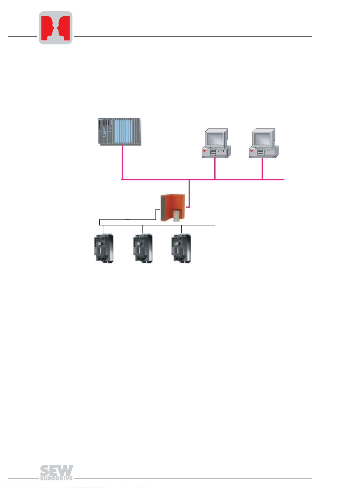
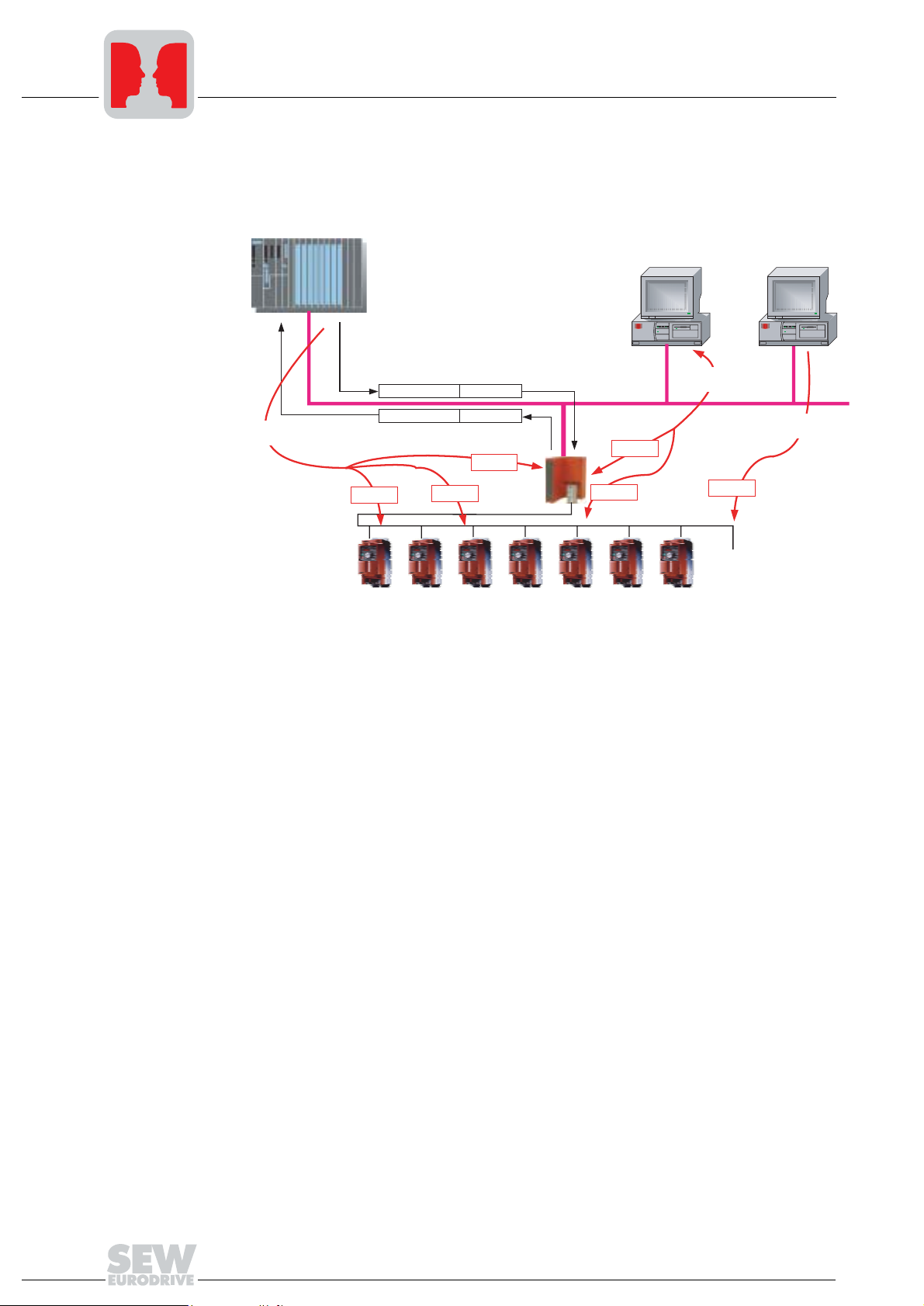
The UFP11A PROFIBUS DP-V1 fieldbus interface is used for connecting inverters with
the PROFIBUS DP-V1. Several inverters can be connected to the UFP11A PROFIBUS
DP-V1 interface via the SBus. The UFP11A PROFIBUS interface establishes the
connection between PROFIBUS DP-VI and SBus.
C1-Master
UFP
PROFIBUS DP-V1
C2-Master
C2-Master
MOVITRAC
Figure 1: System overview DP-V1 master – UFP – inverter
®
07
53453AXX
4
Manual – PROFIBUS UFP11A Fieldbus Interface
Page 5
2Unit Design
Phone: 800.894.0412 - Fax: 888.723.4773 - Web: www.clrwtr.com - Email: info@clrwtr.com
2.1 Front view
Unit Design
Front view
2
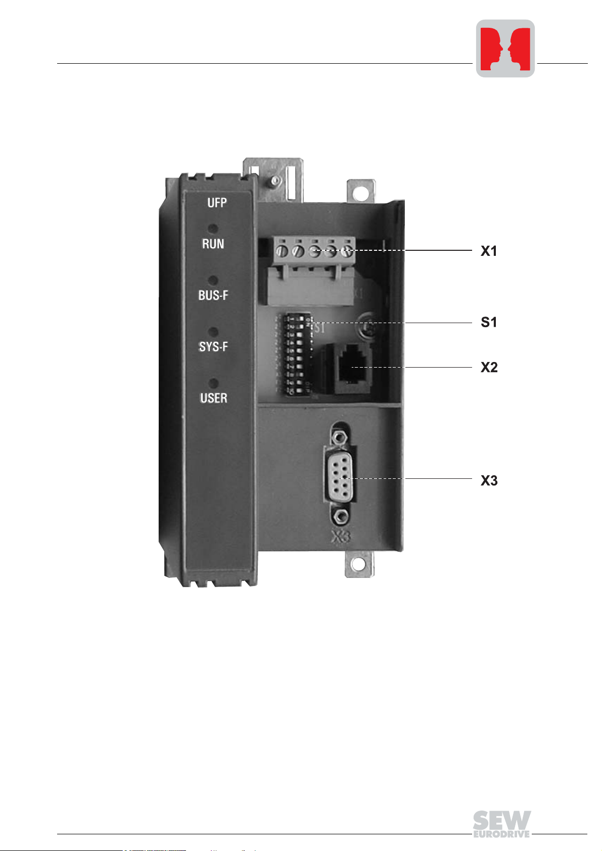
Figure 2: Arrangement of LEDs, connectors and DIP switches
X1 SBus and 24 V connector
X2 Diagnostic interface
X3 PROFIBUS
S1 DIP switch
RUN Operating status
BUS-F Bus fault
SYS-F System fault
USER Expert mode
Manual – PROFIBUS UFP11A Fieldbus Interface
04888AXX
5
Page 6

3
Phone: 800.894.0412 - Fax: 888.723.4773 - Web: www.clrwtr.com - Email: info@clrwtr.com
Installation and Operation without PC
Installation notes
3 Installation and Operation without PC
3.1 Installation notes
Installation
Pin assignment
The unit can be installed directly onto the wall of a control cabinet by using the preinstalled DIN rail mounting or the four drilled holes on the back of the housing. Basically,
there are no restrictions regarding the spatial arrangement of the units to be connected
(e.g. MOVITRAC
®
07). The maximum line length and the fact that the gateway must be
installed at the end or the beginning of the system bus (SBus) must be taken into
consideration. For this reason, we recommend you take the spatial aspects into
account.
The UFP must have additional HF-compliant grounding if the DIN rail mounting option
is used with SBus cables of more than 1 m in length.
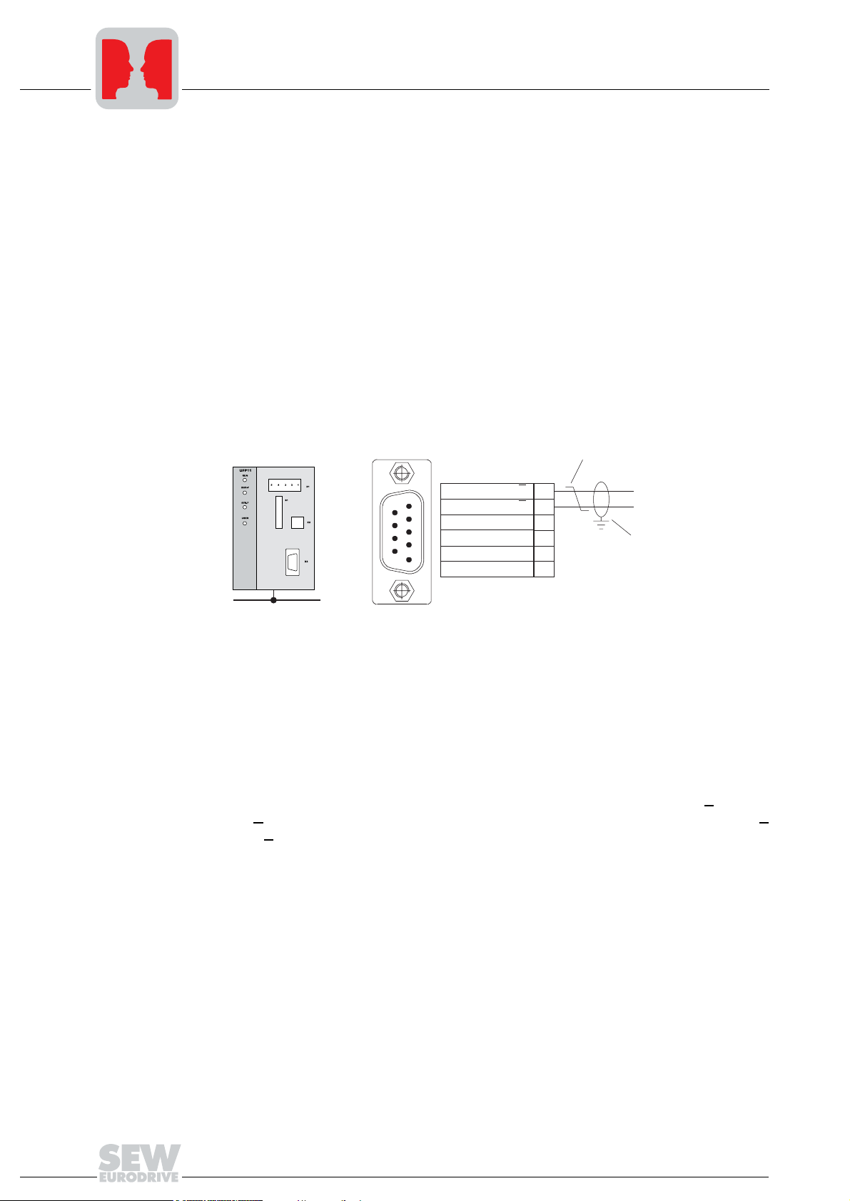
The UFP11A fieldbus interface is connected to the PROFIBUS network by means of a
9-pin sub D connector in accordance with EN 50170. The T-bus connection must be
implemented with an appropriately designed plug.
[2]
[1]
RxD/TxD-P (B/ )B
RxD/TxD-N (A/ )A
CNTR-P
DGND (M5V)
VP (P5V)
DGND (M5V)
3
8
4
5
6
9
[3]
Fieldbus connector
Figure 3: Assignment of 9-pin sub D connector X3 according to EN 50170 ([1] = 9-pin sub D
connector; [2] = twisted signal lines; [3] = conductive connection between connector
housing and shielding)
01222DXX
The fieldbus interface is generally connected to the PROFIBUS system using a shielded
twisted-pair cable. The shielding of the PROFIBUS cable must be attached to both
sides, for example on the connector housing. Observe the maximum supported
transmission rate when selecting the bus connector.
The twisted-pair cable is connected to the PROFIBUS connector via pin 8 (A/A
3 (B/B
). Communication takes place via these two contacts. The RS-485 signals A/A
) and pin
and B/B must be contacted in the same way for all PROFIBUS stations. Otherwise, no
communication is possible via the bus medium.
The PROFIBUS interface sends a TTL control signal for a repeater or fiber optic adapter
(reference = pin 9) via pin 4 (CNTR-P).
6
Manual – PROFIBUS UFP11A Fieldbus Interface
Page 7

System bus connection
Phone: 800.894.0412 - Fax: 888.723.4773 - Web: www.clrwtr.com - Email: info@clrwtr.com
Installation and Operation without PC
Installation notes
3
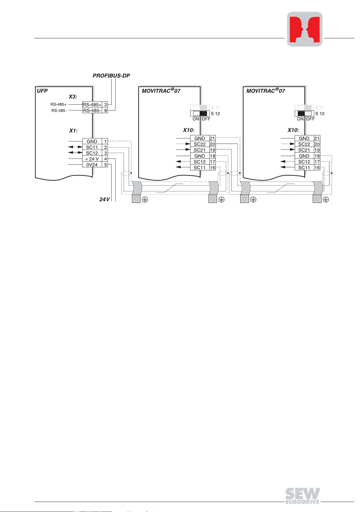
Figure 4: System bus connection
UFP
GND = System bus reference
SC11 = System bus high
SC12 = System bus low
Please note:
• Use a 2-core twisted and shielded copper cable (data transmission cable with
braided copper shield). Connect the shield with a wide-area contact at the electronics
terminal of MOVITRAC
The cable must meet the following specifications (CAN bus or DeviceNet cables are
suitable, for example):
– Core cross section 0.75 mm
– Cable resistance 120 Ω at 1 MHz
– Capacitance per unit length ≤ 40 pF/m (12 pF/ft) at 1 kHz
• The approved total cable length depends on the specified SBus baud rate:
– 250 kbaud: 160 m (528 ft)
– 500 kbaud: 80 m (264 ft)
– 1000 kbaud: 40 m (132 ft)
MOVITRAC® 07
GND = System bus reference
SC22 = System bus low, outgoing
SC21 = System bus high, outgoing
SC12 = System bus low, incoming
SC11 = System bus high, incoming
S12 = System bus terminating resistor
®
07 or UFP11A and also connect the shield ends to GND.
2
(AWG18)
04848AXX
Manual – PROFIBUS UFP11A Fieldbus Interface
7
Page 8

3
Phone: 800.894.0412 - Fax: 888.723.4773 - Web: www.clrwtr.com - Email: info@clrwtr.com
Installation and Operation without PC
Installation notes
• Connect the system bus terminating resistor (S12 = ON) at the end of the system bus
connection. Disconnect the terminating resistor at the other devices (S12 = OFF).
The UFP11A gateway must always be connected either at the beginning or the end
of the system bus connection and feature a permanently installed terminating
resistor.
• There must not be any difference of potential between the units connected with the
SBus. Take suitable measures to avoid a difference of potential, such as connecting
the unit ground connectors using a separate line.
• Point-to-point wiring is not permitted.
24 V connection
Shielding and
routing of bus
cables
An external 24 V voltage supply must be connected to terminals X1:4 and X1:5.
The PROFIBUS interface supports the RS-485 communications protocol and requires
cable type A specified for PROFIBUS in accordance with EN 50170 as shielded twistedpair cable for the physical connection.
Correct shielding of the bus cable attenuates electrical interference that may occur in
industrial environments. The following measures ensure the best possible shielding:
• Tighten the mounting screws on the connectors, modules and equipotential bonding
conductors by hand.
• Use only connectors with metal housing or plated housing.
• Connect the shielding in the connector with the greatest possible surface area.
• Attach the shielding of the bus line on both sides.
• Do not route signal and bus cables parallel to power cables (motor leads). They must
be routed in separate cable ducts.
• Use metallic, grounded cable racks in industrial environments.
• Route the signal cable and the corresponding equipotential bonding in close
proximity using the shortest way possible.
• Avoid using plug connectors to extend bus cables.
• Route the bus cables closely along existing grounding surfaces.
In case of fluctuations in the earth potential, a compensating current may flow via the
bilaterally connected shield that is also connected to the protective earth (PE). Make
sure you supply adequate equipotential bonding according to relevant VDE regulations
in such a case.
8
Manual – PROFIBUS UFP11A Fieldbus Interface
Page 9

Installation and Operation without PC
Phone: 800.894.0412 - Fax: 888.723.4773 - Web: www.clrwtr.com - Email: info@clrwtr.com
Setting the inverter parameters
3
Bus termination
A bus termination is not provided on the UFP electronics. If the UFP module is used as
the first or last device of the PROFIBUS line, the bus termination has to be external. We
recommend PROFIBUS connectors with integrated bus termination that open the
continuing bus in case the bus termination is connected.
3.2 Setting the inverter parameters
The settings can be entered via the inverter keypad. Refer to the operating instructions
of the inverter for details.
• Connect the voltage supply for the UFx and all connected inverters.
• Set an individual SBus address (P813) at the inverters. Recommendation: Address
setting beginning with address 1 in ascending order based on the arrangement of
inverters in the control cabinet. Address 0 should not be assigned because it is used
by the UFx.
• Verify the SBus baud rate (P816, factory setting = 500 kbaud).
• Set the setpoint source (P100) to SBus (value 10).
• Set the control source (P101) to SBus (value 3).
• Set the terminal assignment of the binary inputs. For MOVITRAC
recommended for P60-. This corresponds to the following assignment:
– DI01 CW/Stop (wired to 24 V, both directions of rotation enabled)
– DI02 CCW/Stop (no function)
– DI03 F.Setp. toggle(not wired)
– DI04 n11/n21 (not wired)
– DI05 n12/n22 (not wired)
– If you use a MOVIDRIVE
are not used to "No function."
• Important: For MOVITRAC
PC, if necessary. The default value is 0, which means timeout monitoring is
deactivated. Set P815 to the value 1 s.
®
07, the value 0 is
®
unit as inverter, you must program the terminals that
®
07, P815 SBus timeout interval can only be adjusted via
Manual – PROFIBUS UFP11A Fieldbus Interface
9
Page 10

3
Phone: 800.894.0412 - Fax: 888.723.4773 - Web: www.clrwtr.com - Email: info@clrwtr.com
3.3 Autosetup
Installation and Operation without PC
Autosetup
The Autosetup function allows startup of the UFx to be performed without a PC. Activate
the function via the Autosetup DIP switch. Switching on the Autosetup DIP switch
causes the function to be performed once.
in ON position.
again. First, the UFx searches the lower-level SBUS for drive inverters. This process is
indicated by the SYS-FAULT LED flashing briefly. For this purpose, different SBus
addresses must be set for the drive inverters (P813). We recommend assigning the
addresses beginning with address 1 in ascending order based on the arrangement of
inverters in the control cabinet. The process image on the fieldbus side is expanded by
three words for each detected drive inverter. If no inverter is detected, the SYS-FAULT
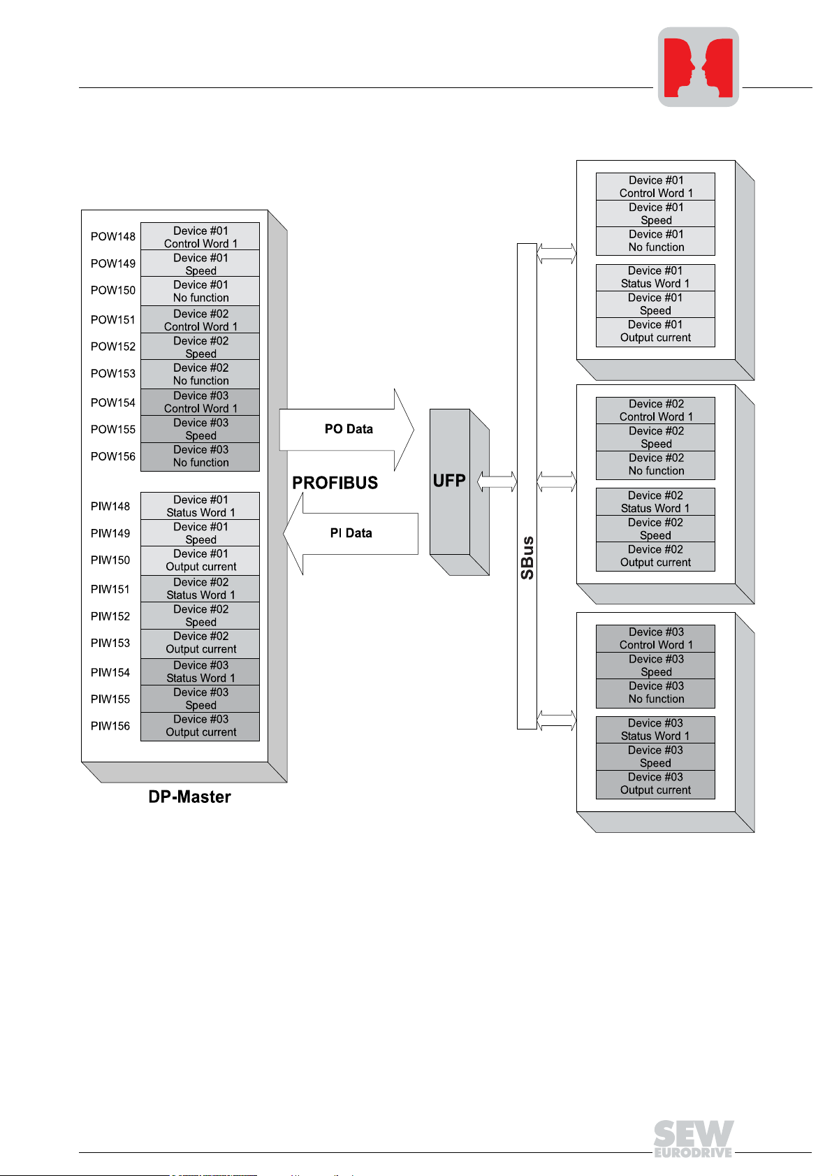
LED remains lit. A total of up to eight drive inverters is taken into account. The figure
shows the process image for three drive inverters with three words each of process
output data and process input data. After the search is complete, the UFx cyclically
exchanges three process data words with each connected drive inverter. The process
output data are fetched from the fieldbus, divided into blocks of three and transmitted.
The drive inverters read the process input data, put them together and send them to the
fieldbus master.
Important: If you change the process data assignment of the drive inverters connected
to the UFP, you have to activate Autosetup again because the UFP saves these values
only once during Autosetup. At the same time, the process data assignments of the
connected drive inverters may not be changed dynamically after Autosetup.
The function can be reactivated by turning the DIP switch off and back on
The Autosetup DIP switch must then remain
10
Manual – PROFIBUS UFP11A Fieldbus Interface
Page 11
Installation and Operation without PC
Phone: 800.894.0412 - Fax: 888.723.4773 - Web: www.clrwtr.com - Email: info@clrwtr.com
Autosetup
3
Figure 5: Data exchange DP-V1 master – UFP – inverter
Manual – PROFIBUS UFP11A Fieldbus Interface
04843AXX
11
Page 12
3
Phone: 800.894.0412 - Fax: 888.723.4773 - Web: www.clrwtr.com - Email: info@clrwtr.com
Installation and Operation without PC
Project planning of the fieldbus master
3.4 Project planning of the fieldbus master
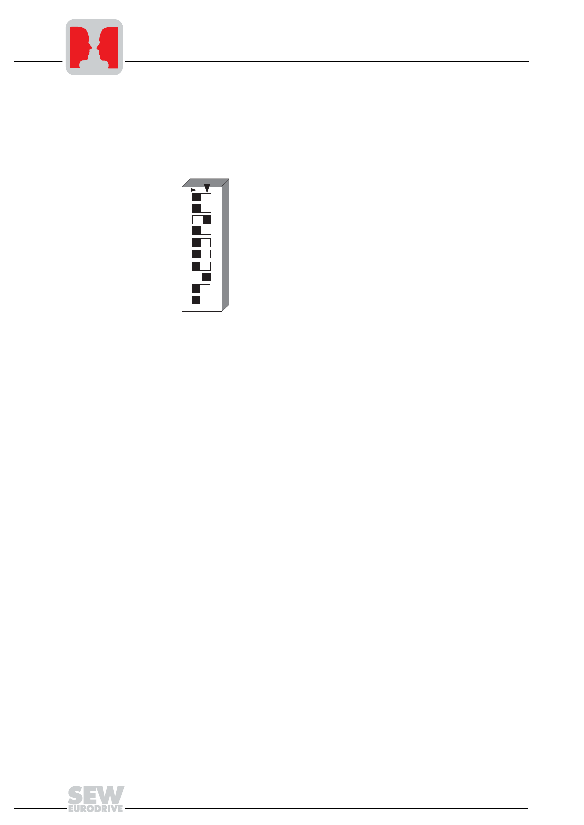
• Set an individual PROFIBUS address using the DIP switches of the UFP for project
planning. The PROFIBUS address is set in binary form. A change of the PROFIBUS
address only becomes effective after switching the UFP off and on again.
X = on
1 2 3 4 5 6 7 8 9 10
2
2
2
2
2
2
2
AS
F1
F2
0
1
2
3
4
5
6
1: x 0 = +0
2: x 0 = +0
4: x 1 = +4
8: x 0 = +0
16: x 0 = +0
32: x 0 = +0
64: x 0 = +0
= 4
Figure 6: Setting the PROFIBUS station address
50341AXX
• The fieldbus master is configured using the GSD file (see appendix). The UFP is
addressed under the specified PROFIBUS address. The number of process data
words the fieldbus master uses to address the UFP depends on the number of
connected inverters. The process data width for an inverter is three words. If more
than one inverter is present, three words should be planned for each inverter. For
example, you have to configure nine words for three MOVITRAC
®
07 inverters.
• Example for STEP 7:
– Install the GDS file in the STEP 7 software.
– In HW config of the hardware catalog, insert the UFP at the PROFIBUS.
– Select the setting suitable for your application from the presented process data
configurations, for example "9PD", meaning nine process data words for three
inverters.
– Save the configuration.
– Expand your application program by the data exchange with the UFP. For this
purpose, use the system functions of S7 for consistent data exchange (SFC14
and SFC15).
– The BUS-FAULT LED of the UFP should be extinguished after saving the project,
loading it in the DP-V1 master and starting the DP-V1 master. If this is not the
case, check the connections and terminating resistors of the PROFIBUS and the
project planning, especially the PROFIBUS address in STEP 7.
12
Manual – PROFIBUS UFP11A Fieldbus Interface
Page 13

3.5 Starting the inverters
Phone: 800.894.0412 - Fax: 888.723.4773 - Web: www.clrwtr.com - Email: info@clrwtr.com
You can operate up to eight inverters on the PROFIBUS using one UFP. The DP master
and the UFP exchange the setpoints and actual values of all inverters connected to the
UFP in coherent data packages. It is important for you to know which inverter is located
at which position of the data package (process image). Figure 5 shows the relationship.
The inverters are enabled by writing the value 0006h to the corresponding control
word 1. The speed setpoint can be specified with the following word. It is scaled with
0.2 1/min per digit.
For more information on the unit profile of MOVITRAC
07 Communication" manual.
Installation and Operation without PC
Starting the inverters
®
07, refer to the "MOVITRAC
3
®
Manual – PROFIBUS UFP11A Fieldbus Interface
13
Page 14
4
Phone: 800.894.0412 - Fax: 888.723.4773 - Web: www.clrwtr.com - Email: info@clrwtr.com
Installation and Operation with PC
Installation notes
4 Installation and Operation with PC
4.1 Installation notes
Installation
Pin assignment
The unit can be installed directly onto the wall of a control cabinet by using the preinstalled DIN rail mounting or the four drilled holes on the back of the housing. Basically,
there are no restrictions regarding the spatial arrangement of the units to be connected
(e.g. MOVITRAC
®
07). The maximum line length and the fact that the gateway must be
installed at the end or the beginning of the system bus (SBus) must be taken into
consideration. For this reason, we recommend you take the spatial aspects into
account.
The UFP must have additional HF-compliant grounding if the DIN rail mounting option
is used with SBus cables of more than 1 m in length.
The UFP11A fieldbus interface is connected to the PROFIBUS network by means of a
9-pin sub D connector in accordance with EN 50170. The T-bus connection must be
implemented with an appropriately designed plug.
[2]
[1]
RxD/TxD-P (B/ )B
RxD/TxD-N (A/ )A
CNTR-P
DGND (M5V)
VP (P5V)
DGND (M5V)
3
8
4
5
6
9
[3]
Fieldbus connector
Figure 7: Assignment of 9-pin sub D connector X3 according to EN 50170 ([1] = 9-pin sub D
connector; [2] = twisted signal lines; [3] = conductive connection between connector
housing and shielding)
01222DXX
The fieldbus interface is generally connected to the PROFIBUS system using a shielded
twisted-pair cable. The shielding of the PROFIBUS cable must be attached to both
sides, for example on the connector housing. Observe the maximum supported
transmission rate when selecting the bus connector.
The twisted-pair cable is connected to the PROFIBUS connector via pin 8 (A/A
3 (B/B
). Communication takes place via these two contacts. The RS-485 signals A/A
) and pin
and B/B must be contacted in the same way for all PROFIBUS stations. Otherwise, no
communication is possible via the bus medium.
The PROFIBUS interface sends a TTL control signal for a repeater or fiber optic adapter
(reference = pin 9) via pin 4 (CNTR-P).
14
Manual – PROFIBUS UFP11A Fieldbus Interface
Page 15
System bus connection
Phone: 800.894.0412 - Fax: 888.723.4773 - Web: www.clrwtr.com - Email: info@clrwtr.com
Installation and Operation with PC
Installation notes
4
Figure 8: System bus connection
UFP
GND = System bus reference
SC11 = System bus high
SC12 = System bus low
Please note:
• Use a 2-core twisted and shielded copper cable (data transmission cable with
braided copper shield). Connect the shield with a wide-area contact at the electronics
terminal of MOVITRAC
The cable must meet the following specifications (CAN bus or DeviceNet cables are
suitable, for example):
– Core cross section 0.75 mm
– Cable resistance 120 Ω at 1 MHz
– Capacitance per unit length ≤ 40 pF/m (12 pF/ft) at 1 kHz
• The approved total cable length depends on the specified SBus baud rate:
– 250 kbaud: 160 m (528 ft)
– 500 kbaud: 80 m (264 ft)
– 1000 kbaud: 40 m (132 ft)
MOVITRAC® 07
GND = System bus reference
SC22 = System bus low, outgoing
SC21 = System bus high, outgoing
SC12 = System bus low, incoming
SC11 = System bus high, incoming
S12 = System bus terminating resistor
®
07 or UFP11A and also connect the shield ends to GND.
2
(AWG18)
04848AXX
Manual – PROFIBUS UFP11A Fieldbus Interface
15
Page 16

4
Phone: 800.894.0412 - Fax: 888.723.4773 - Web: www.clrwtr.com - Email: info@clrwtr.com
Installation and Operation with PC
Installation notes
• Connect the system bus terminating resistor (S12 = ON) at the end of the system bus
connection. Disconnect the terminating resistor at the other devices (S12 = OFF).
The UFP11A gateway must always be connected either at the beginning or the end
of the system bus connection and feature a permanently installed terminating
resistor.
• There must not be any difference of potential between the units connected with the
SBus. Take suitable measures to avoid a difference of potential, such as connecting
the unit ground connectors using a separate line.
• Point-to-point wiring is not permitted.
24 V connection
Shielding and
routing of bus
cables
An external 24 V voltage supply must be connected to terminals X1:4 and X1:5.
The PROFIBUS interface supports the RS-485 communications protocol and requires
cable type A specified for PROFIBUS in accordance with EN 50170 as shielded twistedpair cable for the physical connection.
Correct shielding of the bus cable attenuates electrical interference that may occur in
industrial environments. The following measures ensure the best possible shielding:
• Tighten the mounting screws on the connectors, modules and equipotential bonding
conductors by hand.
• Use only connectors with metal housing or plated housing.
• Connect the shielding in the connector with the greatest possible surface area.
• Attach the shielding of the bus line on both sides.
• Do not route signal and bus cables parallel to power cables (motor leads). They must
be routed in separate cable ducts.
• Use metallic, grounded cable racks in industrial environments.
• Route the signal cable and the corresponding equipotential bonding in close
proximity using the shortest way possible.
• Avoid using plug connectors to extend bus cables.
• Route the bus cables closely along existing grounding surfaces.
16
In case of fluctuations in the earth potential, a compensating current may flow via the
bilaterally connected shield that is also connected to the protective earth (PE). Make
sure you supply adequate equipotential bonding according to relevant VDE regulations
in such a case.
Manual – PROFIBUS UFP11A Fieldbus Interface
Page 17

Installation and Operation with PC
Phone: 800.894.0412 - Fax: 888.723.4773 - Web: www.clrwtr.com - Email: info@clrwtr.com
Setting the inverter parameters
4
Bus termination
A bus termination is not provided on the UFP electronics. If the UFP module is used as
the first or last device of the PROFIBUS line, the bus termination has to be external. We
recommend PROFIBUS connectors with integrated bus termination that open the
continuing bus in case the bus termination is connected.
4.2 Setting the inverter parameters
The settings can be entered via the inverter keypad. Refer to the operating instructions
of the inverter for details.
• Connect the voltage supply for the UFx and all connected inverters.
• Set an individual SBus address (P813) at the inverters. Recommendation: Address
setting beginning with address 1 in ascending order based on the arrangement of
inverters in the control cabinet. Address 0 should not be assigned because it is used
by the UFx.
4.3 Startup software
• Install the MOVITOOLS software package version 2.70 or higher on your PC.
• Start the software. Select the COM to which the UFP is connected and press the
"Update" button. The UFP should appear at address 0 and the connected inverters
at the following addresses. If the window does not show an entry, check the COM
interface and the connection via UWS21. If the UFP is the only entry in the window,
check the SBus cabling and the terminating resistors.
• Select UFx and call up the startup software for the fieldbus gateway (UFx
configurator).
• Select the "Reconfigure fieldbus node" menu item.
• Select your project path and project name. Press the "Next" button.
• Press the "Update" button. All inverters connected to the UFP should be displayed
now. The configuration can be customized using the "Insert," "Change" and "Delete"
buttons. Press the "Next" button.
• Press the "Autoconfiguration" button. The process image for the UFP will now appear
in your controller. The process data width is shown at the bottom. This value is
important for the project planning of the fieldbus master. Press the "Next" button.
• Save the project data and press the "Download" button. The Autosetup DIP switch
must be in OFF position for this purpose.
Manual – PROFIBUS UFP11A Fieldbus Interface
17
Page 18
4
Phone: 800.894.0412 - Fax: 888.723.4773 - Web: www.clrwtr.com - Email: info@clrwtr.com
Installation and Operation with PC
Starting the inverters
• The data exchanged between fieldbus master and the UFP can be viewed with the
process data monitor.
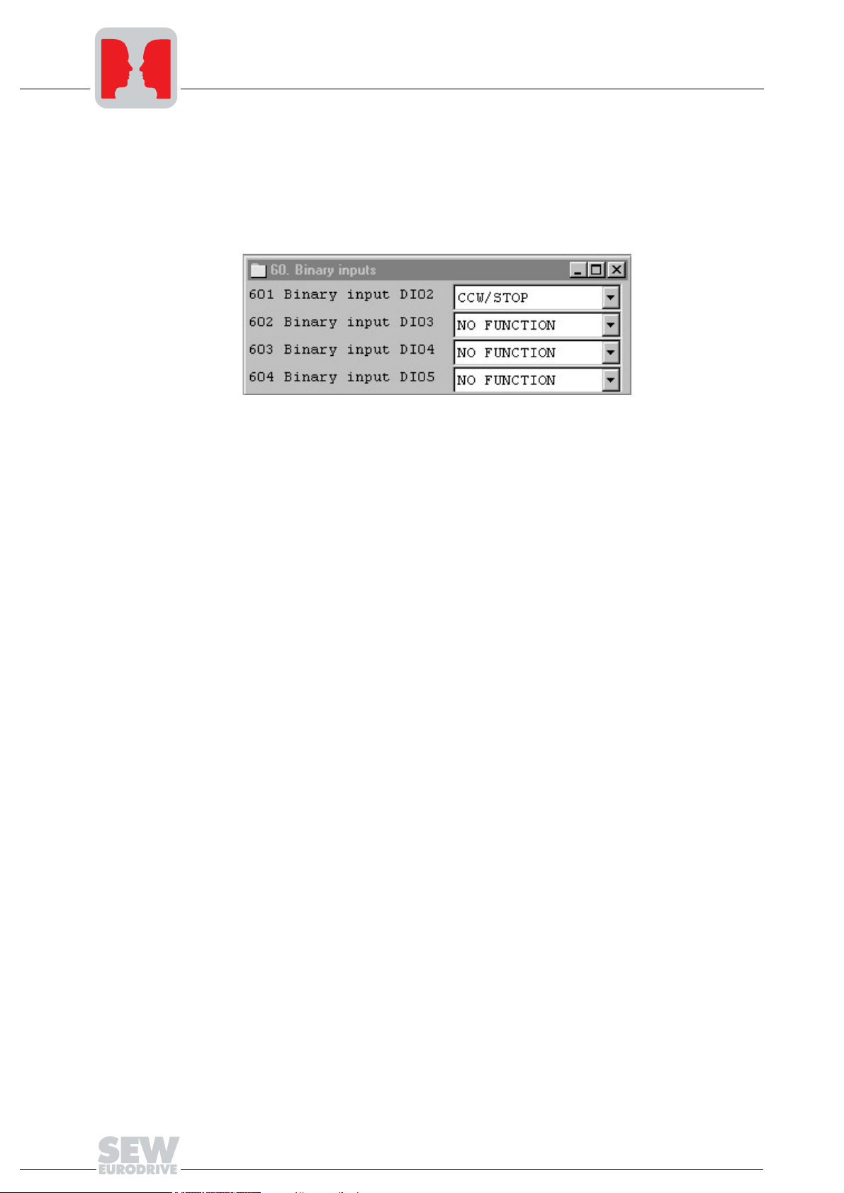
• Enabling on the terminal side is required to control the inverters via fieldbus. You
have already wired the terminals. To check the terminal assignment, select the first
inverter with address 1 in the "Connected inverters" window and start Shell. For
MOVITRAC
• Repeat the previous step for all inverters displayed in the "Connected inverters"
window.
®
07, the terminal assignment should be set as follows:
4.4 Starting the inverters
You can operate up to eight inverters on the PROFIBUS using one UFP. The DP master
and the UFP exchange the setpoints and actual values of all inverters connected to the
UFP in coherent data packages. It is important for you to know which inverter is located
at which position of the data package (process image). The process data monitor
indicates the relationship in the project planning of the fieldbus gateway (UFx
configurator).
The inverters are enabled by writing the value 0006h to the corresponding control
word 1. The speed setpoint can be specified with the following word. It is scaled with
0.2 1/min per digit.
For more information on the unit profile of MOVITRAC
07 Communication" manual.
®
07, refer to the "MOVITRAC
®
18
Manual – PROFIBUS UFP11A Fieldbus Interface
Page 19

5 PROFIBUS interface
Phone: 800.894.0412 - Fax: 888.723.4773 - Web: www.clrwtr.com - Email: info@clrwtr.com
5.1 Startup up PROFIBUS DP master
Supporting files for UFP are available in the Internet at sew-eurodrive web site.
• Observe the notes in the README.TXT file on the GSD disk.
• Install the GSD file according to the requirements of the project planning software for
the DP master. After successful installation, the "UFP" device appears in the list of
slave stations.
• Insert the interface module into the PROFIBUS structure under the name "UFP" and
assign the PROFIBUS address.
• Select the process data configuration required for your application (see next section).
• Enter the I/O or peripheral addresses for the configured data widths.
• Save the configuration.
• Expand your application program by the data exchange with the fieldbus interface.
In case of S7, use the system functions for consistent data exchange for this purpose
(SFC14 and SFC15).
• The BUS-FAULT LED of the fieldbus interface should extinguish after you have
saved the project, loaded it in the DP-V1 master and started the DP-V1 master. If this
is not the case, check the connections and terminating resistors of the PROFIBUS
and the project planning, especially the PROFIBUS address.
PROFIBUS interface
Startup up PROFIBUS DP master
5
5.2 Configuration of the PROFIBUS DP interface
General
information
The inverter must be given a specific DP configuration by the DP master to define type
and number of input and output data used for the transmission. You have the opportunity
to control the drives via process data and to read or write all parameters of the fieldbus
interface via parameter channel.
Manual – PROFIBUS UFP11A Fieldbus Interface
19
Page 20
5
c
Phone: 800.894.0412 - Fax: 888.723.4773 - Web: www.clrwtr.com - Email: info@clrwtr.com
PROFIBUS interface
Configuration of the PROFIBUS DP interface
The figure shows a schematic view of the data exchange between automation device
8DP-V1 master), fieldbus interface (DP-V1 slave) and an inverter with process data
channel and parameter channel.
C1-Master
Process data
configuration
C2-Master
Cyclic OUT Data
Param PD
yclic DPV1
1-Services
Axis = 1
Axis = SBus-Address: 12345678
Param PD
Cyclic IN Data
Axis = 0
Axis = 3
Axis = 0
Axis = 5
Acyclic DPV1
C2-Services
PROFIBUS DPV1
Axis = 8
C2-Master
Acyclic DPV1
C2-Services
53129BXX
Figure 9: Data exchange with parameter data (Param) and process data (PD)
The fieldbus interface allows for different DP configurations for the data exchange
between DP master and fieldbus interface. The following table provides additional
details on all standard DP configurations of the fieldbus interfaces. The "Process data
configuration" column shows the name of the configuration. These texts also appear as
a selection list in your project planning software for the DP master. The DP
configurations column shows the type of configuration data sent to the fieldbus interface
while the link to PROFIBUS DP is being established. The configurations are determined
by the default process data width for SEW inverters of three process data words. In the
simplest case, the controller transmits three process data words to each inverter
connected to the fieldbus interface. The fieldbus interface then distributes these process
data words to the individual devices. The parameter channel is used for setting the
parameters of the UFP and is not passed on to the connected participants. The fieldbus
interface accepts 1 ... 24 process data words with and without parameter channel.
20
Manual – PROFIBUS UFP11A Fieldbus Interface
Page 21

PROFIBUS interface
Phone: 800.894.0412 - Fax: 888.723.4773 - Web: www.clrwtr.com - Email: info@clrwtr.com
Configuration of the PROFIBUS DP interface
The standard entries of the GSD file are based on the UFP Autosetup operating mode
and allow process data widths of 3PD ... 24PD according to 1 ... 8 inverters connected
to the fieldbus interface.
A maximum of 3PDs can be assigned to any SBus participant!
5
ONE module for all
drives
The process data are transmitted in one consistent data block for all inverters connected
to the fieldbus interface. Thus, only system functions SFC14 and SFC15 need to be
activated in Step 7.
UFP parameter +
ONE module
The configurations under "UFP parameter + ONE module" correspond to those listed
above. The parameter module that allows for a parameter setting of the UFP with eight
consistently transmitted bytes will be processed first. Refer to the "MOVITRAC
Communication" manual for information on the parameter channel.
One module per
drive
One consistent data block exists for each connected inverter. From the controller side,
this corresponds to the existing setup of several inverters with their own fieldbus
interface. System functions SFC14 and SFC15 need to be executed for each inverter in
Step 7.
UFP parameter +
One module per
drive
The configurations under "UFP parameter + One module" correspond to those listed
above. The parameter module which allows for a parameter setting of the fieldbus
interface using eight consistently transmitted bytes will be processed first. Refer to the
"MOVITRAC
®
07 Communication" manual for information on the parameter channel.
Drive parameters of connected MOVITRAC® 07 inverters can only be accessed using
the DP-V1 parameter services.
Process data
configuration
ONE module for all drives
AS 1 drive (3 PD) Control via 3 process data words 0 242
AS 2 drives (6 PD) Control via 6 process data words 0 245
AS 3 Drives (9 PD) Control via 9 process data words 0 248
AS 4 Drives
(12 PD)
AS 5 Drives
(15 PD)
AS 6 Drives
(18 PD)
AS 7 Drives
(21 PD)
AS 8 Drives
(24 PD)
Meaning / notes
Control via 12 process data words 0 251
Control via 15 process data words 0 254
Control via 18 process data words 0 192 209 209
Control via 21 process data words 0 192 212 212
Control via 24 process data words 0 192 215 215
Cfg0 Cfg1 Cfg2 Cfg3 Cfg4 Cfg5 Cfg6 Cfg7 Cfg8
®
07
Manual – PROFIBUS UFP11A Fieldbus Interface
21
Page 22

5
Phone: 800.894.0412 - Fax: 888.723.4773 - Web: www.clrwtr.com - Email: info@clrwtr.com
PROFIBUS interface
Configuration of the PROFIBUS DP interface
Process data
configuration
UFP parameter + ONE module
AS 1 Drive
(Param + 3PD)
AS 2 Drives
(Param + 6PD)
AS 3 Drives
(Param + 9PD)
AS 4 Drives
(Param + 12PD)
AS 5 Drives
(Param + 15PD)
AS 6 Drives
(Param + 18PD)
AS 7 Drives
(Param + 21PD)
AS 7 Drives
(Param + 24PD)
One module per drive
AS 1 Drive
(1 x 3PD)
AS 2 Drives
(2 x 3PD)
AS 3 Drives
(3 x 3PD)
AS 4 Drives
(4 x 3PD)
AS 5 Drives
(5 x 3PD)
AS 6 Drives
(6 x 3PD)
AS 7 Drives
(7 x 3PD)
AS 8 Drives
(8 x 3PD)
Meaning / notes
Control via 3 process data words /
parameter setting via 8-byte
parameter channel
Control via 6 process data words /
parameter setting via 8-byte
parameter channel
Control via 9 process data words /
parameter setting via 8-byte
parameter channel
Control via 12 process data words
/ parameter setting via 8-byte
parameter channel
Control via 15 process data words
/ parameter setting via 8-byte
parameter channel
Control via 18 process data words
/ parameter setting via 8-byte
parameter channel
Control via 21 process data words
/ parameter setting via 8-byte
parameter channel
Control via 24 process data words
/ parameter setting via 8-byte
parameter channel
Control via 1x3 process data
words
Control via 2x3 process data
words
Control via 3x3 process data
words
Control via 4x3 process data
words
Control via 5x3 process data
words
Control via 6x3 process data
words
Control via 7x3 process data
words
Control via 8x3 process data
words
Cfg0 Cfg1 Cfg2 Cfg3 Cfg4 Cfg5 Cfg6 Cfg7 Cfg8
243 242
243 245
243 248
243 251
243 254
243 192 209 209
243 192 212 212
243 192 215 215
0 242
0 242 242
0 242 242 242
0 242 242 242 242
0 242 242 242 242 242
0 242 242 242 242 242 242
0 242 242 242 242 242 242 242
0 242 242 242 242 242 242 242 242
22
Manual – PROFIBUS UFP11A Fieldbus Interface
Page 23

PROFIBUS interface
Phone: 800.894.0412 - Fax: 888.723.4773 - Web: www.clrwtr.com - Email: info@clrwtr.com
Configuration of the PROFIBUS DP interface
5
Process data
configuration
UFP parameter + one module per drive
AS 1 Drive
(Param + 1 x 3PD)
AS 2 Drives
(Param + 2 x 3PD)
AS 3 Drives
(Param +3 x 3PD)
AS 4 Drives
(Param + 4 x 3PD)
AS 5 Drives
(Param + 5 x 3PD)
AS 6 Drives
(Param + 6 x 3PD)
AS 7 Drives
(Param + 7 x 3PD)
AS 8 Drives
(Param + 8 x 3PD)
Meaning / notes
Control via 1x3 process data
words / parameter setting via 8byte parameter channel
Control via 2x3 process data
words / parameter setting via 8byte parameter channel
Control via 3x3 process data
words / parameter setting via 8byte parameter channel
Control via 4x3 process data
words / parameter setting via 8byte parameter channel
Control via 5x3 process data
words / parameter setting via 8byte parameter channel
Control via 6x3 process data
words / parameter setting via 8byte parameter channel
Control via 7x3 process data
words / parameter setting via 8byte parameter channel
Control via 8x3 process data
words / parameter setting via 8byte parameter channel
Cfg0 Cfg1 Cfg2 Cfg3 Cfg4 Cfg5 Cfg6 Cfg7 Cfg8
243 242
243 242 242
243 242 242 242
243 242 242 242 242
243 242 242 242 242 242
243 242 242 242 242 242 242
243 242 242 242 242 242 242 242
243 242 242 242 242 242 242 242 242
"Universal module"
DP configuration
The "Universal Module" configuration (e.g. in STEP7) allows you to set the parameters
of the fieldbus interface deviating from the preset standard values of the GSD file. This
is useful in case you want to operate several inverters with different process data words
at the fieldbus interface.
You must observe the following conditions:
• Module 0 defines the parameter channel of the inverter. Entering 0 will switch off the
parameter channel; entering 243 will switch on the parameter channel with 8 bytes
length.
• The following modules determine the process data width of the fieldbus interface at
the PROFIBUS. The added process data width of all following modules must be
between 1 and 24 words. For safety reasons, the modules must be listed with data
integrity. Make sure that an inverter connected to the fieldbus interface is
represented by such a consistent module entry.
• The special identifier format is permitted.
Manual – PROFIBUS UFP11A Fieldbus Interface
23
Page 24

5
Phone: 800.894.0412 - Fax: 888.723.4773 - Web: www.clrwtr.com - Email: info@clrwtr.com
PROFIBUS interface
Configuration of the PROFIBUS DP interface
The following figure shows the structure of the configuration data defined in EN 50170
(V2). These configuration data are transmitted to the inverter during the initial start of the
DP master.
Table 1: Format of the Cfg_Data identifier byte according to EN 50170 (V2)
7 / MSB 6 5 4 3 2 1 0 / LSB
Data length
0000 = 1 byte/word
1111 = 1 6 byte s/wor ds
Input/output
00 = special identifier formats
01 = input
02 = output
11 = input/output
Format
0 = byte structure
1 = word structure
Integrity over
0 = byte or word
1 = entire length
Data integrity
External
diagnostics
Note on Simatic S7
Master Systems
Note:
Use only the setting "Integrity over entire length" for data transmission!
Integral data are those data that must always be transmitted consistently between
automation device and inverter and may never be transmitted separately.
Data integrity is especially important for the transmission of positioning values or
complete positioning tasks. Inconsistent transmission may contain data from different
program cycles of the automation device and transfer undefined values to the inverter.
For PROFIBUS DP, the data communication always between automation device and
drive engineering is generally carried out with the setting "Data integrity over entire
length."
The fieldbus interface does not support external diagnostics. Error messages of the
individual inverters are indicated by the corresponding status words. Error states of the
fieldbus interface are also displayed on status word 1, for example, timeout of the SBus
connection to a participant.
Upon request, the fieldbus interface provides the standard diagnostics in accordance
with EN 50170 V2.
Diagnostic alarms may also be triggered by the PROFIBUS DP system in the DP master
even if external diagnostic generation is deactivated. As a result, the corresponding
operating blocks (e.g. OB84 for S7-400 or OB82 for S7-300) should always be created
in the controller.
24
Manual – PROFIBUS UFP11A Fieldbus Interface
Page 25

5.3 Ident number
Phone: 800.894.0412 - Fax: 888.723.4773 - Web: www.clrwtr.com - Email: info@clrwtr.com
Each DP master and DP slave must have an individual ident number assigned by the
PROFIBUS user group for unique identification of the connected unit. When the
PROFIBUS DP master is started up, it compares the ident numbers of the connected
DP slaves with the ident numbers configured by the user. The user data transfer will only
be activated after the DP master has ensured that the connected station addresses and
device types (ident numbers) correspond to the project planning data. This procedure
achieves a high degree of safety with respect to project planning errors.
The ident number for the UFP11A fieldbus interface is 6004
The ident number is defined as an unsigned 16-bit number (Unsigned16). The
PROFIBUS user group specified ident number 6004 hex (24580 dec) for the UFP11A
fieldbus interface.
5.4 Inverter control
The inverter is controlled via the process data channel which is one, two or three I/O
words in length. These process data words may mapped in the I/O or peripheral area of
the controller in case a programmable controller is used as DP master and can be
addressed as usual.
PROFIBUS interface
Ident number
hex.
5
POW318
POW316
POW314
POW312
POW310
POW308
[1]
PIW318
PIW316
PIW314
PIW312
PIW310
PIW308
Figure 10: Mapping of PROFIBUS data in the PLC address range ([1] = parameter channel / [2] =
PLC address range / U/f = inverter)
PO 3
PO 2
PO 1
PO 3
PO 2
PO 1
UFP
PI 3
PI 2
PI 1
PI 3
PI 2
PI 1
PO 1
PO 1
PO 2
PO 3
PO 2
PO 3
MOVITRACfi 07 1 MOVITRACfi 07 2
PI 2
PI 1
PI 3
PI 1
PI 2
PI 3
52996AXX
PO = process output data / PI = process input data
Additional information on programming and project planning can be found in the
README_GSD6004.PDF file included in the GSD file.
Manual – PROFIBUS UFP11A Fieldbus Interface
25
Page 26

5
Phone: 800.894.0412 - Fax: 888.723.4773 - Web: www.clrwtr.com - Email: info@clrwtr.com
PROFIBUS interface
Inverter control
Control example
for Simatic S7
STEP7 programming example
The drive inverter is controlled via Simatic S7 in dependence of the selected process
data configuration, either directly via load and transfer commands or via the special
system functions
In principle, data lengths of 3 bytes or more than 4 bytes must be transmitted using
system functions SFC14 and SFC15.
Process data
configuration
1 PD Load/transfer commands
2 PD Load/transfer commands
3 PD ... 24 PD System functions SFC14/15 (length 6 .. 48 bytes)
Param +1 PD Parameter channel: System functions SFC14/15 (length 8 .. 48 bytes)
Param +2 PD Parameter channel: System functions SFC14/15 (length 6 .. 48 bytes)
Param + 3 PD ...
24 PD
The "README_GSD6004.PDF" file contains project planning and programming
examples for Simatic S7.
SFC 14 DPRD_DAT
STEP7 access via
Process data: Load/transfer commands
Process data: Load/transfer commands
Parameter channel: System functions SFC14/15 (length 6 .. 48 bytes)
Process data: System functions SFC14/15 (length 6 bytes)
and
SFC15 DPWR_DAT
.
26
Manual – PROFIBUS UFP11A Fieldbus Interface
Page 27

6 DP-V1 Functions
Phone: 800.894.0412 - Fax: 888.723.4773 - Web: www.clrwtr.com - Email: info@clrwtr.com
6.1 Introduction to PROFIBUS DP-V1
This chapter describes the functions and terms used for operating SEW drive inverters
on PROFIBUS DP-V1. Refer to the PROFIBUS user organization or visit
PROFIBUS website for extensive technical information on PROFIBUS DP-V1.
The PROFIBUS DP-V1 specification introduced new acyclical
the context of the PROFIBUS DP-V1 expansions. These acyclical services are inserted
into special telegrams during ongoing cyclical bus operation and thus ensure
compatibility between PROFIBUS DP (version 0) and PROFIBUS DP-V1 (Version 1).
The acyclical
between master and slave (drive inverter) than it would be possible to transfer in the
cyclical input or output data using the 8-byte parameter channel. The advantage of the
acyclical data exchange via DP-V1 lies in the minimum load on the cyclical bus
operation since DP-V1 telegrams are only added to the bus cycle if required.
The DP-V1 parameter channel provides two options for the user:
• The higher-level controller can access the entire inverter information of the SEW DPV1 slaves. This means not only cyclical process data but also unit settings can be
read, stored in the controller and modified in the slave.
• It is also possible to route the service and startup tool MOVITOOLS across the DPV1 parameter channel instead of using a proprietary RS-485 connection for this
purpose. After installing the MOVITOOLS software, detailed information will be
available in the ...\SEW\MOVITOOLS\Fieldbus folder.
The main features of PROFIBUS DP-V1 are explained below.
read/write
services can be used to exchange larger data quantities
DP-V1 Functions
Introduction to PROFIBUS DP-V1
read/write
6
services within
C1-Master
Acyclic DP-V1
C1-Services
Cyclic OUT Data
Param PD
Param PD
Cyclic IN Data
SEW
Drive
C2-Master
Acyclic DP-V1
C2-Services
PROFIBUS DP-V1
Acyclic DP-V1
C2-Services
C2-Master
53123AXX
Manual – PROFIBUS UFP11A Fieldbus Interface
27
Page 28

6
Phone: 800.894.0412 - Fax: 888.723.4773 - Web: www.clrwtr.com - Email: info@clrwtr.com
DP-V1 Functions
Introduction to PROFIBUS DP-V1
Class 1 master
(C1 master)
Class 2 master
(C2 master)
Data sets (DS)
Different master classes are distinguished in a PROFIBUS DP-V1 network. The C1
master mainly performs the cyclical data exchange with the slaves. A typical C1 master
is a control system, such as a PLC, that exchanges cyclical process data with the slave.
If the DPV1 function has been activated via the GSD file, the acyclical connection
between C1 master and slave is established automatically when the cyclical connection
of the PROFIBUS-DP is being established. Only one C1 master can be operated in a
PROFIBUS DP-V1 network.
The C2 master itself does not perform cyclical data exchange with the slaves. Examples
for a typical C2 master are visualization systems or temporary installed programming
devices (Notebook / PC). The C2 master uses exclusively acyclical connections for the
communication with the slaves. The acyclical connections between C2 master and slave
are established by the
completed
with the slaves by means of
in a DP-V1 network. The number of C2 connections, which are established to a slave
simultaneously, are determined by the slave. SEW drive inverters support two parallel
C2 connections.
The user data transported via DP-V1 service are collected in a data set. Each data set
is uniquely represented through its length, a slot number and an index. The DP-V1
communication with the SEW drive inverter uses the structure of data set 47, which is
defined as DP-V1 parameter channel for drives starting with V3.1 in the PROFIdrive
profile drive engineering of the PROFIBUS user organization. Different access
procedures to the parameter data of the drive inverter are provided via this parameter
channel.
Initiate
Initiate
service. The connection is established after successfully
service. An established connection allows for cyclical data exchange
Read
or
Write
services. Several C2 masters can be active
DP-V1 services
DP-V1 alarm
handling
The DP-V1 expansions offer new services, which can be used for acyclical data
exchange between master and slave. The following services are provided:
C1 master Connection type: MSAC1 (master/slave acyclical C1)
Read Read data set
Write Write data set
C2 master Connection type: MSAC2 (master/slave acyclical C2)
INITIATE Establish C2 connection
ABORT Disconnect C2 connection
Read Read data set
Write Write data set
The DP-V1 specification not only defines acyclical services, but also includes expanded
alarm handling. Alarm handling distinguishes between different alarm types. As a result,
the unit-specific diagnostics via the DP-V1 service "DDLM_SlaveDiag" is not possible
anymore in DP-V1 operation. No DP-V1 alarm handling was defined for drive
engineering as the drive inverter generally transmits status informaton via cyclical
process data communication.
28
Manual – PROFIBUS UFP11A Fieldbus Interface
Page 29

6.2 Features of SEW drive inverters
r
Phone: 800.894.0412 - Fax: 888.723.4773 - Web: www.clrwtr.com - Email: info@clrwtr.com
The SEW fieldbus interfaces according to PROFIBUS DP-V1 have the same
communication features for the DP-V1 interface. Basically, the drives are controlled via
a C1 master according to the DP-V1 standard with cyclical process data. In the case of
cyclical data exchange, the C1 master (usually a PLC) can additionally use an 8-byte
parameter channel to perform parameter services with the UFP. The UFP cannot
access connected MOVITRAC
write services give the C1 master access to connected participants via the DP-V1 C1
channel.
Two C2 channels can be established in addition to these two parameter channels. The
first C2 master can use the C2 channel, for example, to read parameter data as
visualization. A second C2 master in the form of a notebook configures the drive using
MOVITOOLS.
DP-V1 Functions
Features of SEW drive inverters
®
07 drives via this parameter channel. The read and
6
C1-Master
8 Byte Param
DP:
DP:
PD
DP-V1 Interface
SEW PROFIBUS
Cyclic IN/Out
Process Data
Figure 11: DP-V1 parameter channels
Acyclic DP-V1
C1-Services
Drive System
Acyclic DP-V1
C2-Services
C1-Parameterbuffer
DP Parameterbuffer
cyclic
Parameterbuffer
C2-Master C2-Maste
PROFIBUS DP-V1
Acyclic DP-V1
C2-Services
C2-Parameterbuffer
C2-Parameterbuffer
53124AXX
Manual – PROFIBUS UFP11A Fieldbus Interface
29
Page 30

6
Phone: 800.894.0412 - Fax: 888.723.4773 - Web: www.clrwtr.com - Email: info@clrwtr.com
DP-V1 Functions
Structure of the DP-V1 parameter channel
6.3 Structure of the DP-V1 parameter channel
On principle, the parameter setting of the drives to the PROFIdrive DPV1 parameter
channel of profile version 3.0 is implemented via data set index 47. The
is used to distinguish between parameter access based on PROFIdrive profile or via
SEW MoviLink services. The following table shows the possible codings of the individual
elements. The data set structure is the same for PROFIdrive and MoviLink access.
Request ID
entry
DP-V1
Read/Write
The following MoviLink services are supported:
• 8-byte MoviLink parameter channel with all the services supported by the drive
inverter such as
– Read parameter
– Write parameter
– Write parameter volatile
–etc.
PROFIdrive
Parameter Channel
DS47
SEW MoviLink
30
Manual – PROFIBUS UFP11A Fieldbus Interface
Page 31

DP-V1 Functions
Phone: 800.894.0412 - Fax: 888.723.4773 - Web: www.clrwtr.com - Email: info@clrwtr.com
Structure of the DP-V1 parameter channel
The following PROFIdrive services are supported:
• Reading (request parameter) individual parameters of the type
• Writing (change parameter) individual parameters of the type
Table 2: Elements of data set DS47
Field Data type Values
Request
Reference
Request ID Unsigned8 0x01 Request parameter (PROFIdrive)
Response ID Unsigned8 Response (+):
Axis Unsigned8 0x00 ... 0xFF Number of axis 0 ... 255
No. of parameters
Attributes Unsigned8 0x10 Value
Unsigned8 0x00 Reserved
0x01 ... 0xFF
0x02 Change parameter (PROFIdrive)
0x40 SEW MoviLink service
0x00 Reserved
0x01 Request parameter (+) (PROFIdrive)
0x02 Change parameter (+) (PROFIdrive)
0x40 SEW MoviLink service (+)
Response (–):
0x81 Request parameter (–) (PROFIdrive)
0x82 Change parameter (–) (PROFIdrive)
0xC0 SEW MoviLink service (–)
Unsigned8 0x01 ... 0x13 1 ... 19 DWORDs (240 DP-V1 data bytes)
double word
double word
6
For SEW MoviLink (Request ID = 0x40):
0x00 No service
0x10 Read Parameter
0x20 Write Parameter
0x30 Write Parameter volatile
0x40 ... 0xF0 Reserved
No. of Elements Unsigned8 0x00 for non-indexed parameters
Parameter Number
Subindex Unsigned16 0x0000 SEW: always 0
Format Unsigned8 0x43 Double word
No. of Values Unsigned8 0x00 ... 0xEA Quantity 0 ... 234
Error Value Unsigned16 0x0000 ... 0x0064 PROFIdrive error codes
Unsigned16 0x0000 ... 0xFFFF MoviLink parameter index
0x01 ... 0x75 Quantity 1 ... 117
0x44 Error
0x0080 + MoviLink-AdditionalCode Low
For SEW MoviLink 16 bit error value
Manual – PROFIBUS UFP11A Fieldbus Interface
31
Page 32

6
Phone: 800.894.0412 - Fax: 888.723.4773 - Web: www.clrwtr.com - Email: info@clrwtr.com
DP-V1 Functions
Structure of the DP-V1 parameter channel
Procedure for
setting
parameters via
data set 47
Parameter access takes place with the combination of the DP-V1 services
Read
. The parameter setting service is transferred to the slave with
Write.req
Write
and
, followed
by slave-internal processing.
The master now sends a
master repeats the
Read.req
Read.req
responds with a positive response
to pick up the parameter setting response. The
if the
Read.res
Read.res
from the slave is negative. The slave
as soon as parameter processing in the
drive inverter is finished. The user data now contain the parameter setting response of
the parameter setting order that was previously sent with
Write.req
(see figure). This
mechanism applies to a C1 as well as a C2 master.
Master
Parameter
Request
PROFIBUS-DP-V1
Write.req DS47
with data (parameter request)
Write.res
without data
Read.req DS47
without data
Read.res(-)
without data
Slave (Drive)
Parameter
Request
Parameter
Processing
Read.req DS47
without data
Parameter
Response
Figure 12: Telegram sequence for parameter access via DP-V1
with data (parameter response)
Read.res(+)
Parameter
Response
53126AXX
32
Manual – PROFIBUS UFP11A Fieldbus Interface
Page 33

DP-V1 Functions
Phone: 800.894.0412 - Fax: 888.723.4773 - Web: www.clrwtr.com - Email: info@clrwtr.com
Structure of the DP-V1 parameter channel
6
Procedure for the
DP-V1 master
If the bus cycle time is short, the parameter response is queried earlier than the inverter
has completed the parameter access in the unit. As a result, the response data from the
inverter are not yet ready at this time. In this state, the inverter sends a negative
response on DP-V1 level with Error_Code _1 = 0xB5 (status fault). The DP-V1 master
must then send another request with above Read.req header until the drive inverter
sends a positive response.
Send Write.request
with Parameterdata
Check Write.
response
Send DS_Read.req
with Parameterdata
Read.
response
State
Conflict?
Write.response
Write.response
positive
yes
negative
no
Other Errors
or Timeout
no
Parameter transfer
ok, data available
yes
Parameter transfer
aborted with ERROR
53127AXX
Manual – PROFIBUS UFP11A Fieldbus Interface
33
Page 34

6
Phone: 800.894.0412 - Fax: 888.723.4773 - Web: www.clrwtr.com - Email: info@clrwtr.com
DP-V1 Functions
Structure of the DP-V1 parameter channel
Addressing a
UFP with connected MOVIT-
®
RAC
07 units
The structure of the DS47 data set defines an axis element. With the setting
Axis = 0
the UFP is accessed directly. The SBus address of the corresponding inverter must be
entered in the axis element for addressing a connected MOVITRAC
C1-Master
Cyclic OUT Data
Param PD
Acyclic DP-V1
C1-Services
Axis = 1
Axis = SBus-Address: 12345678
Param PD
Cyclic IN Data
Axis = 0
Axis = 3
Axis = 0
Axis = 5
®
C2-Master
Acyclic DP-V1
C2-Services
07.
PROFIBUS DP-V1
Axis = 8
C2-Master
Acyclic DP-V1
C2-Services
53129BXX
,
MoviLink
parameter orders
The MoviLink parameter channel of the SEW drive inverters is directly mapped in the
structure of data set 47. The Request ID 0x40 (SEW MoviLink service) is used for the
exchange of MoviLink parameter setting orders. Parameter access with MoviLink
services usually takes place according to the structure described below. The typical
message sequence for data set 47 is used for this purpose.
Request ID: 0x40 SEW MoviLink Service
The actual service is defined by the data set element
Attribute
on the MoviLink
parameter channel. The high nibble of this element corresponds to the service nibble in
the management byte of the DPV0 parameter channel.
34
Manual – PROFIBUS UFP11A Fieldbus Interface
Page 35

DP-V1 Functions
Phone: 800.894.0412 - Fax: 888.723.4773 - Web: www.clrwtr.com - Email: info@clrwtr.com
Structure of the DP-V1 parameter channel
6
Example for reading a parameter via
MoviLink
The following tables show an example of the structure of the Write.request and Read.res
user data for reading an individual parameter via the MoviLink parameter channel.
Sending parameter order
The following tables show the coding of the user data for the
the DP-V1 header. The
Write.req
service is used to transfer the parameter setting order
Write.req
service including
to the drive inverter. The firmware version is read.
Table 3: Excerpt from the parameter list ("MOVITRAC® 07 Communication" manual)
Par.
Parameter
no.
0.. Display values
07. Unit data
070 Unit type 8301 206D 0 RO 0
071 Rated output current 8361 20A9 A –3 RO 0
076 Firmware basic unit 8300 206C 0 RO 0
Table 4: Write.request header for transferring the parameter order
Service: Write.request
Slot_Number 0 Random, (is not evaluated)
Index 47 Index of the data set; constant index 47
Length 10 10 byte user data for parameter order
Table 5: Write.req USER DATA for MoviLink "read parameter"
Byte Field Value Description
0 Request Reference 0x01 Individual reference number for the parameter
1 Request ID 0x40 SEW MoviLink Service
2 Axis 0x01 Drive number; 1 = SBus address
3 No. of parameters 0x01 1 parameter
4 Attributes 0x10 MoviLink service “Read parameter”
5 No. of Elements 0x00 0 = access to direct value, no subelement
6..7 Parameter Number 0x206C MoviLink index 8300 = “firmware version”
8..9 Subindex 0x0000 Subindex 0
Index Unit/index
Dec Hex Abbr. Cv.
Access Default Meaning / value range
Example:
822609711 = 822 609 7.11
1822609011 = 822 609 X.11
setting order that is reflected in the parameter
response
Manual – PROFIBUS UFP11A Fieldbus Interface
35
Page 36

6
Phone: 800.894.0412 - Fax: 888.723.4773 - Web: www.clrwtr.com - Email: info@clrwtr.com
DP-V1 Functions
Structure of the DP-V1 parameter channel
Requesting the parameter response
The following table shows the coding of the Read.req user data including the DP-V1
header.
Table 6: Read.req for requesting the parameter response
Service: Write.request
Slot_Number 0 Random, (is not evaluated)
Index 47 Index of the data set; constant index 47
Length 10 10 byte user data for parameter order
Positive MoviLink parameter response
The table shows the Read.res USER DATA with the positive response data of the
parameter setting order. The parameter value for index 8300 (firmware version) is
returned as an example.
Table 7: DP-V1 header of the positive Read.response with parameter response
Service: Read.request
Slot_Number 0 Random, (is not evaluated)
Index 47 Index of the data set; constant index 47
Length 10 10 byte user data in response buffer
Table 8: Positive response for MoviLink service
Byte Field Value Description
0 Response reference 0x01 Mirrored reference number from the parameter
setting order
1 Response ID 0x40 Positive MoviLink response
2 Axis 0x01 Mirrored drive number; 1 = SBus address
3 No. of parameters 0x01 1 parameter
4 Format 0x43 Parameter format: Double word
5 No. of values 0x01 1 value
6..7 Value Hi 0x311C Higher-order part of the parameter
8..9 Value Lo 0x7289 Lower-order part of the parameter
Decoding:
0x 311C 7289 = 823947913 dec
>> firmware version 823 947 9.13
36
Manual – PROFIBUS UFP11A Fieldbus Interface
Page 37

DP-V1 Functions
Phone: 800.894.0412 - Fax: 888.723.4773 - Web: www.clrwtr.com - Email: info@clrwtr.com
Structure of the DP-V1 parameter channel
6
Example for writing
a parameter via
MoviLink
The following tables show an example of the structure of the
Write
and
Read
services.
Speed 123 rpm (Ⳏ value 123 000) is to be written volatile to P160 internal value n11.
The MoviLink service
Table 9: Excerpt from the parameter list ("MOVITRAC® 07 Communication" manual)
Par.
Parameter
no.
16. Fixed setpoints 1
160 Internal setpoint n11 8489 2129 rps 66 N/RW 150000
161 Internal setpoint n12 8490 212A rps 66 N/RW 750000
Write Parameter volatile
Index Unit/index
Dec Hex Abbr. Cv.
is used for this purpose.
Access Default Meaning / value range
–5000000 ... –0, Step 200
0 ... 5000000, Step 200
–5000000 ... –0, Step 200
0 ... 5000000, Step 200
Send „Write parameter volatile“ order
Table 10: DP-V1 header of the Write.request with parameter order
Service: Write.request
Slot_Number 0 Random, (is not evaluated)
Index 47 Index of the data set; constant index 47
Length 16 16 byte user data for order buffer
Table 11: Write.req user data for MoviLink service "Write parameter volatile"
Byte Field Value Description
0 Request Reference 0x01 Individual reference number for the parameter
1 Request ID 0x40 SEW MoviLink Service
2 Axis 0x01 Drive number; 1 = SBus address
3 No. of parameters 0x01 1 parameter
4 Attributes 0x30 MoviLink service “Write parameter volatile”
5 No. of Elements 0x00 0 = access to direct value, no subelement
6..7 Parameter Number 0x2129 Parameter index 8489 = P160 n11
8..9 Subindex 0x0000 Subindex 0
10 Format 0x43 Double word
11 No. of values 0x01 Change 1 parameter value
12..13 Value HiWord 0x0001 Higher-order part of the parameter value
14..15 Value LoWord 0xE078 Lower-order part of the parameter value
setting order that is reflected in the parameter
response
After sending this Write.request, the Write.response is received. If there was no status
conflict in processing the parameter channel, a \positive Write.response occurs.
Otherwise, the status error is located in Error_code_1.
Manual – PROFIBUS UFP11A Fieldbus Interface
37
Page 38

6
Phone: 800.894.0412 - Fax: 888.723.4773 - Web: www.clrwtr.com - Email: info@clrwtr.com
DP-V1 Functions
Structure of the DP-V1 parameter channel
Requesting the parameter response
The following table shows the coding of the Write.req USER DATA including the DP-V1
header.
Table 12: Read.req for requesting the parameter response
Field Value Description
Function_Num Read.req
Slot_Number X Slot_Number not used
Index 47 Index of data set
Length 240 Maximum length of response buffer in DP-V1 master
Positive response to “Write Parameter volatile”
Table 13: DP-V1 header of the positive Read.response with parameter response
Service: Read.response
Slot_Number 0 Random, (is not evaluated)
Index 47 Index of the data set; constant index 47
Length 4 12 byte user data in response buffer
Table 14: Positive response for MoviLink service „Write Parameter'
Byte Field Value Description
0 Response reference 0x01 Mirrored reference number from the parameter
setting order
1 Response ID 0x40 Positive MoviLink response
2 Axis 0x01 Mirrored drive number; 1 = SBus address
3 No. of parameters 0x01 1 parameter
38
Manual – PROFIBUS UFP11A Fieldbus Interface
Page 39

DP-V1 Functions
Phone: 800.894.0412 - Fax: 888.723.4773 - Web: www.clrwtr.com - Email: info@clrwtr.com
Structure of the DP-V1 parameter channel
6
Negative parameter response
MoviLink return
codes for parameter setting for
DP-V1
The following table shows the coding of a negative response of a MoviLink service. Bit 7
is set in the Response ID if the response is negative.
Table 15: Negative response for MoviLink service
Service: Read.response
Slot_Number 0 Random, (is not evaluated)
Index 47 Index of the data set; constant index 47
Length 8 8 byte user data in response buffer
Byte Field Value Description
0 Response reference 0x01 Mirrored reference number from the parameter
1 Response ID 0xC0 Negative MoviLink response
2 Axis 0x01 Mirrored drive number; 1 = SBus address
3 No. of parameters 0x01 1 parameter
4Format 0x44 Error
5 No. of values 0x01 1 error code
6..7 Error value 0x0811 MoviLink return code
setting order
z. B. ErrorClass 0x08, Add. Code 0x11
(see the table MoviLink return codes for DP-V1)
The following table shows the return codes that are returned by the SEW DP-V1
interface in case of an error in the DP-V1 parameter access.
MoviLink
Return code (hex)
0x0810 Illegal index, parameter index does not exist in the unit
0x0811 Function/parameter not implemented
0x0812 Read access only
0x0813 Parameter lock is active
0x0814 Factory setting is active
0x0815 Value too large for parameter
0x0816 Value too small for parameter
0x0817 Required option card not installed
0x0818 Error in system software
0x0819 Parameter access via RS-485 process interface only
0x081A Parameter access via RS-485 diagnostic interface only
0x081B Parameter has access protection
0x081C Controller inhibit is required
0x081D Illegal value for parameter
0x081E Factory setting was activated
0x081F Parameter was not saved in EEPROM
0x0820 Parameter cannot be changed with output stage enabled / reserved
0x0821 Reserved
0x0822 Reserved
0x0823 Parameter may be changed at IPOS program stop only
0x0824 Parameter may only be changed with deactivated Autosetup
0x0505 Incorrect coding of management and reserved byte
0x0602 Communication error between inverter system and fieldbus option card
0x0502 Timeout of secondary connection (e.g. during reset or with Sys-Fault)
Description
Manual – PROFIBUS UFP11A Fieldbus Interface
39
Page 40

6
Phone: 800.894.0412 - Fax: 888.723.4773 - Web: www.clrwtr.com - Email: info@clrwtr.com
DP-V1 Functions
Structure of the DP-V1 parameter channel
PROFIdrive
parameter orders
Example for reading a parameter via
PROFIdrive
The PROFIdrive parameter channel of SEW drive inverters is directly mapped in the
structure of data set 47. Parameter access with PROFIdrive services usually takes place
according to the structure described below. The typical message sequence for data
set 47 is used for this purpose. PROFIdrive only defines the two request IDs
Request ID:0x01Request Parameter (PROFIdrive)
Request ID:0x02Change Parameter (PROFIdrive)
That is why data access is limited compared to the MoviLink services.
The request ID = 0x02 = Change Parameter (PROFIdrive) results in a remanent write
access to the selected parameter. Consequently, the internal flash/EEPROM of the
inverter is written with each write access. Use the MoviLink service "Write Parameter
volatile" if parameters must be written cyclically at short intervals. With this service, you
alter the parameter values only in the RAM of the inverter.
The following tables show an example of the structure of the Write.request and Read.res
user data for reading an individual parameter via the MoviLink parameter channel.
Sending parameter order
The following tables show the coding of the user data for the Write.req service including
the DP-V1 header. The Write.req service is used to transfer the parameter setting order
to the drive inverter.
Table 16: Write.request header for transferring the parameter order
Service: Write.request
Slot_Number 0 Random, (is not evaluated)
Index 47 Index of the data set; constant index 47
Length 10 10 byte user data for parameter order
Table 17: Write.req USER DATA for MoviLink "read parameter"
Byte Field Value Description
0 Request Reference 0x01 Individual reference number for the parameter
setting order that is reflected in the parameter
response
1 Request ID 0x01 Request parameter (PROFIdrive)
2 Axis 0x01 Drive number; 1 = SBus address
3 No. of parameters 0x01 1 parameter
4 Attributes 0x10 Access to parameter value
5 No. of Elements 0x00 0 = access to direct value, no subelement
6..7 Parameter Number 0x206C MoviLink index 8300 = “firmware version”
8..9 Subindex 0x0000 Subindex 0
40
Manual – PROFIBUS UFP11A Fieldbus Interface
Page 41

DP-V1 Functions
Phone: 800.894.0412 - Fax: 888.723.4773 - Web: www.clrwtr.com - Email: info@clrwtr.com
Structure of the DP-V1 parameter channel
Requesting the parameter response
The following table shows the coding of the Read.req user data including the DP-V1
header.
Table 18: Read.req for requesting the parameter response
Service: Read.request
Slot_Number 0 Random, (is not evaluated)
Index 47 Index of the data set; constant index 47
Length 240 Maximum length of response buffer in the DP-V1 master
Positive PROFIdrive parameter response
The table shows the Read.res user data with the positive response data of the
parameter setting order. The parameter value for index 8300 (firmware version) is
returned as an example.
Table 19: DP-V1 header of the positive Read.response with parameter response
Service: Read.request
Slot_Number 0 Random, (is not evaluated)
Index 47 Index of the data set; constant index 47
Length 10 10 byte user data in response buffer
Table 20: Positive response for MoviLink service
Byte Field Value Description
0 Response reference 0x01 Mirrored reference number from the parameter
setting order
1 Response ID 0x01 Positive response for „Request Parameter“
2 Axis 0x01 Mirrored drive number; 1 = SBus address
3 No. of parameters 0x01 1 parameter
4 Format 0x43 Parameter format: Double word
5 No. of values 0x01 1 value
6..7 Value Hi 0x311C Higher-order part of the parameter
8..9 Value Lo 0x7289 Lower-order part of the parameter
Decoding:
0x 311C 7289 = 823947913 dec
>> firmware version 823 947 9.13
6
Manual – PROFIBUS UFP11A Fieldbus Interface
41
Page 42

6
Phone: 800.894.0412 - Fax: 888.723.4773 - Web: www.clrwtr.com - Email: info@clrwtr.com
DP-V1 Functions
Structure of the DP-V1 parameter channel
Example for writing
a parameter via
PROFIdrive
The following tables show an example of the structure of the
Write
and
Read
services
for the remanent writing of the internal setpoint n11 (see "Example for writing a
parameter via MoviLink"). The PROFIdrive service
Change Parameter
is used for this
purpose.
Send „Write parameter volatile“ order
Table 21: DP-V1 header of the Write.request with parameter order
Service: Write.request
Slot_Number 0 Random, (is not evaluated)
Index 47 Index of the data set; constant index 47
Length 16 16 byte user data for order buffer
Table 22: Write.req user data for MoviLink service "Write parameter volatile"
Byte Field Value Description
0 Request Reference 0x01 Individual reference number for the parameter
1 Request ID 0x02 Change parameter (PROFIdrive)
2 Axis 0x01 Drive number; 1 = SBus address
3 No. of parameters 0x01 1 parameter
4 Attributes 0x10 Access to parameter value
5 No. of Elements 0x00 0 = access to direct value, no subelement
6..7 Parameter Number 0x7129 Parameter index 8489 = P160 n11
8..9 Subindex 0x0000 Subindex 0
10 Format 0x43 Double word
11 No. of values 0x01 Change 1 parameter value
12..13 Value HiWord 0x0001 Higher-order part of the parameter value
14..15 Value LoWord 0xE078 Lower-order part of the parameter value
setting order that is reflected in the parameter
response
After sending this Write.request, the Write.response is received. If there was no status
conflict in processing the parameter channel, a \positive Write.response occurs.
Otherwise, the status error is located in Error_code_1.
Requesting the parameter response
The table shows the coding of the Write.req user data including the DP-V1 header.
Table 23: Read.req for requesting the parameter response
Field Value Description
Function_Num Read.req
Slot_Number X Slot_Number not used
Index 47 Index of data set
Length 240 Maximum length of response buffer in DP-V1 master
42
Manual – PROFIBUS UFP11A Fieldbus Interface
Page 43

DP-V1 Functions
Phone: 800.894.0412 - Fax: 888.723.4773 - Web: www.clrwtr.com - Email: info@clrwtr.com
Structure of the DP-V1 parameter channel
Positive response to “Write Parameter volatile”
Table 24: DP-V1 header of the positive Read.response with parameter response
Service: Read.response
Slot_Number 0 Random, (is not evaluated)
Index 47 Index of the data set; constant index 47
Length 4 12 byte user data in response buffer
Table 25: Positive response for MoviLink service „Write Parameter'
Byte Field Value Description
0 Response reference 0x01 Mirrored reference number from the parameter
setting order
1 Response ID 0x02 Positive MoviLink response
2 Axis 0x01 Mirrored drive number; 1 = SBus address
3 No. of parameters 0x01 1 parameter
6
Negative parameter response
The following table shows the coding of a negative response of a PROFIdrive service.
Bit 7 is set in the Response ID if the response is negative.
Table 26: Negative response for PROFdrive service
Service: Read.response
Slot_Number 0 Random, (is not evaluated)
Index 47 Index of the data set; constant index 47
Length 8 8 byte user data in response buffer
Byte Field Value Description
0 Response reference 0x01 Mirrored reference number from the parameter
setting order
1 Response ID 0x810x82 Negative response for “Request Parameter” Neg-
ative response for “Change Parameter”
2 Axis 0x00 Mirrored drive number; 1 = SBus address
3 No. of parameters 0x01 1 parameter
4Format 0x44 Error
5 No. of values 0x01 1 error code
6..7 Error value 0x0811 MoviLink return code
z. B. ErrorClass 0x08, Add. Code 0x11
(see the table MoviLink return codes for DP-V1)
Manual – PROFIBUS UFP11A Fieldbus Interface
43
Page 44

6
Phone: 800.894.0412 - Fax: 888.723.4773 - Web: www.clrwtr.com - Email: info@clrwtr.com
DP-V1 Functions
Structure of the DP-V1 parameter channel
PROFIdrive return
codes for DP-V1
The following table shows the coding of the error number in the PROFIdrive DP-V1
parameter response according to PROFIdrive profile V3.1. This table applies if you use
the PROFIdrive services "Request Parameter“ or "Change Parameter.“
Error no. Meaning Used at Supplem. info
0x00 Impermissible parameter
number
0x01 Parameter value cannot be
changed
0x02 Low or high limit exceeded Change access with value outside the
0x03 Faulty subindex Access to unavailable subindex Subindex
0x04 No array Access with subindex to non-indexed
0x05 Incorrect data type Change access with value that does not
0x06 Setting not permitted (can
only be reset)
0x07 Description element cannot
be changed
0x08 Reserved (PROFIdrive Profile V2: PPO-Write
0x09 No description data avail-
able
0x0A Reserved (PROFIdrive Profile V2: Access group
0x0B No operation priority Change access without rights to change
0x0C Reserved (PROFIdrive Profile V2: incorrect
0x0D Reserved (PROFIdrive Profile V2: Text cannot be
0x0E Reserved (PROFIdrive Profile V2: Name cannot be
0x0F No text array available Access to text array that is not available
0x10 Reserved (PROFIdrive Profile V2: No PPO-Write )
0x11 Request cannot be exe-
cuted because of operating
state
0x12 Reserved (PROFIdrive Profile V2: other error)
0x13 Reserved (PROFIdrive Profile V2: Data cannot be
0x14 Value impermissible Change access with a value that is within
0x15 Response too long The length of the current response
0x16 Parameter address imper-
missible
0x17 Illegal format Write request: Illegal format or format of
Access to unavailable parameter 0
Change access to a parameter value
that cannot be changed
value limits
parameter
match the data type of the parameter
Change access with value unequal to 0
where this is not permitted
Change access to a description element
that cannot be changed
requested in IR not available)
Access to unavailable description
(parameter value is available)
wrong)
parameters
password)
read in cyclic data transfer)
read in cyclic data transfer)
(parameter value is available)
-
Access is temporarily not possible for
reasons that are not specified in detail
read in cyclic interchange)
the value limits but is not permissible for
other long-term reasons (parameter with
defined single values)
exceeds the maximum transmittable
length
Illegal value or value which is not
supported for the attribute, number of
elements, parameter number or
subindex or a combination
the parameter data which is not
supported
Subindex
Subindex
0
0
Subindex
Subindex
-
0
-
0
-
-
-
0
0
Subindex
0
0
0
44
Manual – PROFIBUS UFP11A Fieldbus Interface
Page 45

DP-V1 Functions
Phone: 800.894.0412 - Fax: 888.723.4773 - Web: www.clrwtr.com - Email: info@clrwtr.com
Structure of the DP-V1 parameter channel
Error no. Meaning Used at Supplem. info
0x18 Number of values are not
consistent
0x19 Axis nonexistent Access to an axis which does not exist -
up to 0x64 Reserved - -
0x65..0xFF Manufacturer-specific - -
Write request: Number of the values of
the parameter data do not match the
number of elements in the parameter
address
0
6
Manual – PROFIBUS UFP11A Fieldbus Interface
45
Page 46

6
Phone: 800.894.0412 - Fax: 888.723.4773 - Web: www.clrwtr.com - Email: info@clrwtr.com
DP-V1 Functions
Project planning for a C1 master
6.4 Project planning for a C1 master
A special GSD file is required for the project planning of a DP-V1 C1 master. This file
activates the DP-V1 functions of the UFP. For this purpose, the GSD file and the
firmware of the UFP must correspond in terms of functions. After introduction of the DPV1 functions, SEW-EURODRIVE supplies two GSD files. Selecting the GSD file: see the
table "Validity of GSD files for UFP."
Validity of GSD
files for UFP
PROFIBUS module UFP
076 firmware basic unit:
823 908 8.10 - .12 ok not possible
823 908 8.13 and higher ok ok
SEW_6004.GSD for DP SEWA6004.GSD for DP-V1
GSD files for DPV1
The GSD files for PROFIBUS DP-V1 are displayed in a special subdirectory in the
project planning software for the DP-V1 master. The figure shows the representation in
the hardware configuration of STEP7.
53131AXX
46
Manual – PROFIBUS UFP11A Fieldbus Interface
Page 47

DP-V1 Functions
Phone: 800.894.0412 - Fax: 888.723.4773 - Web: www.clrwtr.com - Email: info@clrwtr.com
Appendix
6
Operating mode
(DP-V1 mode)
As a rule, the operating mode DP-V1 can be activated during project planning for a C1
master. All DP slaves, which have the DP-V1 functions enabled in their GSD files and
which support DP-V1, will then be operated in the DP-V1 mode. Standard DP slaves
remain to be operated via PROFIBUS DP, which ensures the combined operation of DPV1 and DP-capable modules. A DP-V1 capable participant, which was configured with
the DP-V1 GSD file, can also be operated in the „DP' mode depending on the master
functionality.
6.5 Appendix
Sample program
for SIMATIC S7
Sample function block FB5 „DPV1_Movilink_FB“
FUNCTION_BLOCK FB 5
TITLE =DPV1_Movilink_FB
//NOTE!
//This sample program only shows the basic principles of the procedure.
//Neither legal responsibility nor any kind of liability can be inferred from faulty program functions
//and the consequences thereof!
//
//System requirements:
// DP master connection of the S7-300 or S7-400 series,
// which supports the DPV1 master functions.
// - DPV1 Profibus interfaces from SEW (Identification "SEWA600x.GSD")
//
//This function block performs the parameter exchange between inverter
//and PLC via the DPV1 channel. As the data exchange via the
//DPV1 parameter channel is an acyclical service, the
//function block must be called up until the data exchange is complete
// (duration from triggering the parameter order fActivate and up to
//fDone response).
AUTHOR : SEW
FAMILY : Movilink
VERSION : 0.1
VAR_INPUT
Drive_IO_Address : INT ; //Peripheral address of the inverter
bService : BYTE ; //Movilink service byte 0x01 = read, 0x02 = write, etc.
bAxis : BYTE ; //0 for single axis, subaddress of the axis when using UFP11A
wParameterIndex : WORD ; //Movilink ParameterIndex
wSubIndex : WORD ; //Movilink subindex
dwWriteData : DWORD ; //Write data
InstanzDB_SFB52 : BLOCK_DB ; //InstanzDB of the system function SFB52. Is required for DPV1_READ
InstanzDB_SFB53 : BLOCK_DB ; //InstanzDB of the system function SFB53. Is required for DPV1_WRITE
END_VAR
VAR_OUTPUT
bError : BYTE ; //No error = 0, S7 error = 1, TimeOut = 2, Movilink error = 3;
dwData : DWORD ; //Contains data if fError=0; S7-ErrorCode if fError=1; else not defined
END_VAR
VAR_IN_OUT
fActivate : BOOL ; //Triggering the function
fBusy : BOOL ; //Busy bit. TRUE until the function is finished or timeout monitoring responds
fDone : BOOL ; //Indicates that the function is finished (with or without error)
END_VAR
VAR
fStaticBusy : BOOL ; //Storage bit for busy flag
fStaticWriteReq : BOOL ; //When MVLK WriteReq = TRUE or MVLK ReadReq = FALSE
fDPV1WriteDone : BOOL ; //Indicates whether DPV1 write was performed
fAuxflag : BOOL ;
dwStaticDriveAddr : DWORD ; //I/O address of the inverter
iStaticReqLength : INT ; //Length of the telegrams to be transmitted
MVLK_Req : STRUCT //Movilink structure WriteRequest
RequestReference : BYTE := B#16#1; //REQ: Request Reference
RequestId : BYTE := B#16#40; //REQ: Request ID
Axis : BYTE ; //REQ: Axis
No_of_Parameter : BYTE := B#16#1; //REQ: No. of parameters
Attribute : BYTE ; //REQ: Attributes
No_of_Elements : BYTE ; //REQ: No of elements
ParameterNumber : WORD ; //REQ: Parameter number
Subindex : WORD ; //REQ: Subindex
Format: BYTE := B#16#43;
Values : BYTE := B#16#1;
WriteData : DWORD ; //REQ: WriteData
END_STRUCT ;
TimeoutCounter : WORD ; //Timeout counter
END_VAR
The following STEP7 code shows how parameters are accessed via the STEP7 system
function blocks SFB 52/53. You can copy this code and import/compile it as STEP7
source.
Manual – PROFIBUS UFP11A Fieldbus Interface
47
Page 48

6
Phone: 800.894.0412 - Fax: 888.723.4773 - Web: www.clrwtr.com - Email: info@clrwtr.com
DP-V1 Functions
Appendix
VAR_TEMP
MVLK_Resp : STRUCT //Movilink structure Response
ResponseReference : BYTE ; //RESP: Response reference
ResponseId : BYTE ; //RESP: Response ID
Axis : BYTE ; //RESP: Axis
No_of_Parameter : BYTE ; //RESP: No. of parameters
Attachment : ARRAY [0 .. 7 ] OF //REQ: Data
BYTE ;
END_STRUCT ;
fTempError : BOOL ;
fTempBusy : BOOL ;
fTempDone : BOOL ;
fTempValid : BOOL ;
dwTempStatus : DWORD ;
END_VAR
BEGIN
NETWORK
TITLE =Insert transfer parameter in Movilink structure
U #fActivate;
FP #fAuxflag; //If neither a parameter service is triggered
O #fBusy; //...nor processed,
SPBN END; //...then the function is ended
U #fStaticBusy; //If static busy is set, write service has already been performed,
SPBN NEWR; //then go to new request
U #fDPV1WriteDone; //If write service was finished without error, go to READ
SPB READ;
SPA WRIT; //Else go to WRITE
NEWR: NOP 0; //Initialization:
UN #fStaticBusy; //Output bits and values are reset
S #fStaticBusy; //Busy output and flag bit are set
S #fBusy;
R #fDone; //DoneBit is reset
L 0;
T #bError; //Error and data output values are set to ZERO
T #dwData;
L #Drive_IO_Address; //Convert drive address from Int to DWord
T #dwStaticDriveAddr;
//Store data in Movilink structure (only the variable values of the structure are provided with the input parameters)
L #bAxis;
T #MVLK_Req.Axis;
L #bService; //Service byte is multiplied by 10 hex
SLW 4;
T #MVLK_Req.Attribute;
L #bService;
SPL ERUI; //Go to error MVLK service
SPA ERUI; // 0x00 No service
SPA ZEHN; // 0x01 Read parameter
SPA SEXZ; // 0x02 Write parameter
SPA SEXZ; // 0x03 Write Parameter volatile
SPA ZEHN; // 0x04 Read min
SPA ZEHN; // 0x05 Read max
SPA ZEHN; // 0x06 Read default
SPA ZEHN; // 0x07 Read scale
SPA ZEHN; // 0x08 Read attribute
SPA ZEHN; // 0x09 Read EEPROM
ERUI: NOP 0; // Error illegal MVLK service
L 3; //Movilink error
T #bError;
L DW#16#501; //MLER_ILLEGAL_SERVICE
SET ;
S #fDone; //Busy and done bits are reset
R #fBusy;
R #fStaticBusy;
R #fDPV1WriteDone;
BEA ; //End function
SEXZ: NOP 0;
SET ;
S #fStaticWriteReq; //Indication for data evaluation that request was a MVLK write request
L 16;
SPA LEN; //Go to defined length
ZEHN: NOP 0;
SET ;
R #fStaticWriteReq; //Indication for data evaluation that request was a MVLK read request
L 10;
LEN: NOP 0;
T #iStaticReqLength;
L #wParameterIndex;
T #MVLK_Req.ParameterNumber;
L #wSubIndex;
T #MVLK_Req.Subindex;
L #dwWriteData; //Data are written to the structure disregarding if write or read access
T #MVLK_Req.WriteData;
48
Manual – PROFIBUS UFP11A Fieldbus Interface
Page 49

DP-V1 Functions
Phone: 800.894.0412 - Fax: 888.723.4773 - Web: www.clrwtr.com - Email: info@clrwtr.com
Appendix
NETWORK
TITLE =Write service
//To transfer a parameter request to the inverter, SFB53
//(DPV1 write service) must be called.
WRIT: NOP 0;
CALL SFB 53 , #InstanzDB_SFB53 (
REQ := TRUE,
ID := #dwStaticDriveAddr,
INDEX := 47,//Data set 47
LEN := #iStaticReqLength,
DONE := #fTempDone,
BUSY := #fTempBusy,
ERROR := #fTempError,
STATUS := #dwTempStatus,
RECORD := #MVLK_Req);
//Evaluation of return values
U #fTempBusy; //If the function is not finished, the function block is quit and the busy bit is set
SPB ENDB;
U #fTempError; //If no error has occurred, go to read service preparation.
SPBN RD_V;
SET ; //An error has occurred ! Set error bit and reset busy bits
R #fBusy;
R #fStaticBusy;
R #fDPV1WriteDone;
S #fDone;
L 1; //Issue error code 1 (S7 error)
T #bError;
L #dwTempStatus; //Return the S7 error code
T #dwData;
BEA ;
RD_V: NOP 0; //Preparing the DPV1 read service
SET ;
S #fDPV1WriteDone;
NETWORK
TITLE =Read service
//To fetch the parameter response from the inverter, SFB52
//(DPV1 read service) must be performed.
READ: NOP 0;
CALL SFB 52 , #InstanzDB_SFB52 (
REQ := TRUE,
ID := #dwStaticDriveAddr,
INDEX := 47,//Data set 47
MLEN := 12,
VALID := #fTempValid,
BUSY := #fTempBusy,
ERROR := #fTempError,
STATUS := #dwTempStatus,
LEN := #iStaticReqLength,
RECORD := #MVLK_Resp);
//Evaluation of return values
U #fTempBusy; //If the function is not finished, the function block is quit and the busy bit is set.
SPB ENDB;
U #fTempError; //If no error has occurred, go to data evaluation
SPBN DATA;
L #TimeoutCounter; //Timeout counter is increased
L 1;
+I ;
T #TimeoutCounter;
L #TimeoutCounter; //If the timeout counter has reached 300, a timeout error is triggered
L 300;
>=I ;
SPB TOUT;
//If error xx80B5xx hex (state conflict) is reported, then another parameter order already exists and the read
operation must be repeated
L #dwTempStatus;
UD DW#16#FFFF00;
L DW#16#80B500;
==D ;
SPBN ERR;
NOP 0;
SPA ENDB;
ERR: SET ; //An error has occurred ! Set error bit and reset busy bits
R #fBusy;
R #fStaticBusy;
R #fDPV1WriteDone;
S #fDone;
L 1; //Issue error code 1 (S7 error)
T #bError;
L #dwTempStatus; //Return the S7 error code
T #dwData;
L 0;
T #TimeoutCounter; //Reset timeout counter
BEA ;
6
Manual – PROFIBUS UFP11A Fieldbus Interface
49
Page 50

6
Phone: 800.894.0412 - Fax: 888.723.4773 - Web: www.clrwtr.com - Email: info@clrwtr.com
DP-V1 Functions
Appendix
DATA: NOP 0; //Data evaluation (first selection; positive or negative response)
L #MVLK_Resp.ResponseId;
L B#16#40; //positive Movilink response ?
==I ;
SPB POSR; //go to positive response
L #MVLK_Resp.ResponseId;
L B#16#C0; //negative Movilink response ?
==I ;
SPB NEGR; //go to negative response
SET ; //illegal Movilink response
S #fDone;
R #fBusy;
R #fStaticBusy;
R #fDPV1WriteDone;
L 3; //Movilink error
T #bError;
L DW#16#502; //MLER_NO_RESPONSE
T #dwData;
L 0;
T #TimeoutCounter; //Reset timeout counter
BEA ; //End function
TOUT: NOP 0; //Timeout
L 2; //Movilink error
T #bError;
L 0;
T #dwData;
T #TimeoutCounter; //Reset timeout counter
SET ; //The function is finished:
S #fDone; //=> set done,..reset busy
R #fActivate;
R #fBusy;
R #fStaticBusy;
R #fDPV1WriteDone;
BEA ;
NETWORK
TITLE =Evaluation of the parameter data
POSR: NOP 0;
U #fStaticWriteReq;
SPB WRR; //go to WriteRequestResponse
// //Read request was performed
L #MVLK_Resp.Attachment[2]; //Received data are written to output parameters
SLD 24;
L #MVLK_Resp.Attachment[3];
SLD 16;
+D ;
L #MVLK_Resp.Attachment[4];
SLD 8;
+D ;
L #MVLK_Resp.Attachment[5];
+D ;
T #dwData;
L 0; //no error
T #bError;
SET ; //The function is finished:
S #fDone; //=> set Done, fActivate,... reset
R #fActivate;
R #fBusy;
R #fStaticBusy;
R #fDPV1WriteDone;
L 0;
T #TimeoutCounter; //Reset timeout counter
BEA ;
WRR: NOP 0;
// //Write request was performed
L 0; //Output parameter is filled with ZEROES
T #dwData;
L 0; //no error
T #bError;
SET ; //Clear error bits
S #fDone;
R #fActivate;
R #fBusy;
R #fStaticBusy;
R #fDPV1WriteDone;
L 0;
T #TimeoutCounter; //Reset timeout counter
BEA ;
50
Manual – PROFIBUS UFP11A Fieldbus Interface
Page 51

DP-V1 Functions
Phone: 800.894.0412 - Fax: 888.723.4773 - Web: www.clrwtr.com - Email: info@clrwtr.com
Appendix
NEGR: NOP 0;
L 3; //Movilink error
T #bError;
L #MVLK_Resp.Attachment[2]; //Write error code to output parameter
SLW 8;
L #MVLK_Resp.Attachment[3];
+I ;
T #dwData;
SET ; //The function is finished:
S #fDone; //=> set done,..reset busy
R #fActivate;
R #fBusy;
R #fStaticBusy;
R #fDPV1WriteDone;
L 0;
T #TimeoutCounter; //Reset timeout counter
BEA ;
ENDB: SET ; //Busy end
S #fBusy;
END: NOP 0;
END_FUNCTION_BLOCK
Example of calling up FB5 „DPV1_Movilink_FB“
Insert these lines into your cyclical S7 program for calling up the function block.
FUNCTION FC 1 : VOID
TITLE =Operating the DPV1 parameter channel
//This sample program only shows the basic principles of the procedure.
//Neither legal responsibility nor any kind of liability can be inferred from faulty program functions
//and the consequences thereof!
VERSION : 0.1
BEGIN
NETWORK
TITLE =Writing a MC07 parameter
//In this example, the value 123 rpm is written volatile to
//the internal setpoint n11 (P160). The parameter service can be triggered by a positive edge at
//M100.0 (Variable table "MC07").
//
//The parameter service addresses the MC07 with SBUS address 2.
//
//PROFIBUS address 9
//Per. addr. 512
// I
// UFP11A MC07_1 MC07_2
// I________________I_______________I
// SBUS addr.0 SBUS addr.1 SBUS addr. 2
//
//
//Note on the hardware configuration:
//The periphery addresses ("PIW address" and "POW address") of the UFP11A must have the same
//numerical value to allow that the input "Drive_IO_Address" can be defined
//unambiguously.
//
//
L L#123000; //convert the parameter value from DINT..
T MD 110; //... to DWORD
//Conversion factor/value range of the parameter value: see parameter list in the "MC07 Communication" manual
CALL FB 5 , DB 5 (
Drive_IO_Address := 512,
bService := B#16#3,//0x01 = read, 0x02 = write, 0x03 = write volatile
bAxis := B#16#2,//MC07 with SBUS addr. 2
wParameterIndex := W#16#2129,//MOVILINK parameter index 8489d = P160, internal setpoint n11
wSubIndex := W#16#0,//MOVILINK subindex = 0
dwWriteData := MD 110,//Parameter value that is written
InstanzDB_SFB52 := DB 201,//InstanzDB for SFB52, is required for DPV1_READ
InstanzDB_SFB53 := DB 202,//InstanzDB for SFB53, is required for DPV1_WRITE
bError := MB 118,//no error = 0; S7 error = 1, Timeout = 2, MOVILINK error = 3
dwData := MD 114,//bError = 0 => parameter value that was read; bError = 1 => S7
error code
fActivate := M 100.0,//Activation bit: Triggering a parameter order
fBusy := M 100.1,//The parameter order is being processed or a timeout has occurred
fDone := M 100.2);//The parameter order is complete
END_FUNCTION
6
Manual – PROFIBUS UFP11A Fieldbus Interface
51
Page 52

6
Phone: 800.894.0412 - Fax: 888.723.4773 - Web: www.clrwtr.com - Email: info@clrwtr.com
Technical data
DP-V1 for UFP11
DP-V1 Functions
Appendix
GSD file for DP-V1: SEWA6004.GSD
Module name for project planning: UFP (DP-V1)
Number of parallel C2 connections: 2
Supported data set: Index 47
Supported slot number: Recommendation: 0
Manufacturer code: 10A hex (SEW-EURODRIVE)
Profile ID: 0
C2-Response Timeout 1 s
Max. length C1 channel: 240 bytes
Max. length C2 channel: 240 bytes
52
Manual – PROFIBUS UFP11A Fieldbus Interface
Page 53

DP-V1 Functions
Phone: 800.894.0412 - Fax: 888.723.4773 - Web: www.clrwtr.com - Email: info@clrwtr.com
Appendix
6
Error codes of
the DP-V1
services
This table shows possible error codes of DP-V1 services that may occur in the event of
an error in the communication on DP-V1 telegram level. This table is relevant if you want
to write your own parameter assignment block because the error codes are directly
reported back on the telegram level.
7 6 5 4 3 3 2 0
Bit:
Error_Class
Error_Class (from DPV1 specification)
0x0 ... 0x9 hex =
reserved
0xA = application 0x0 = read error
0xB = access 0x0 = invalid index 0xB0 = No data block Index 47 (DB47);
0xC = resource 0x0 = read constraint conflict
0xD...0xF = user specific
Error_Code (from DP-V1
specification)
0x1 = write error
0x2 = module failure
0x3 to 0x7 = reserved
0x8 = version conflict
0x9 = feature not supported
0xA to 0xF = user specific
0x1 = write length error
0x2 = invalid slot
0x3 = type conflict
0x4 = invalid area
0x5 = state conflict 0xB5 = Access to DB 47 temporarily not
0x6 = access denied
0x7 = invalid range 0xB7 = Write DB 47 with error in the DB 47
0x8 = invalid parameter
0x9 = invalid type
0xA to 0xF = user specific
0x1 = write constraint conflict
0x2 = resource busy
0x3 = resource unavailable
0x4..0x7 = reserved
0x8..0xF = user specific
Error_Code
DP-V1 parameter channel
parameter requests are not supported
possible due to intenal processing status
header
Manual – PROFIBUS UFP11A Fieldbus Interface
53
Page 54

7
Phone: 800.894.0412 - Fax: 888.723.4773 - Web: www.clrwtr.com - Email: info@clrwtr.com
Error Responses
Fieldbus timeout
7 Error Responses
7.1 Fieldbus timeout
7.2 SBUS timeout
Switching off the fieldbus master or an open circuit of the fieldbus cabling leads to a
fieldbus timeout at the UFx. The connected drive inverters are switched to a safe state
by sending zeros to the process output data which corresponds, for example, to a rapid
stop on control word 1. The fieldbus timeout error resets itself, which means the drive
inverters receive the current process output data from the controller once the fieldbus
communication has been reestablished. This error response can be deactivated via
P831 of the UFx.
If one or several drive inverters at the SBus can no longer be addressed by the UFx, the
UFx displays error code 91 "System error" on status word 1 of the respective drive
inverter. The SYS-FAULT LED lights up and the error is also indicated via diagnostic
interface. It is necessary to set the SBus timeout interval P815 of the MOVITRAC
system error to a value other than 0 for the drive inverter to stop. The error resets itself
at the UFx, which means the current process data are exchanged immediately after
restarting the communication.
®
07
7.3 Device errors
UFx gateways detect a series of hardware defects and lock out subsequently. The exact
error responses and remedies can be found in the list of errors. A hardware defect
causes error 91 to be displayed on the fieldbus process input data for status words 1 of
all drive inverters. The SYS-FAULT LED at the UFx then flashes at regular intervals. The
exact error code is displayed via MOVITOOLS in the UFx status at the diagnostic
interface.
54
Manual – PROFIBUS UFP11A Fieldbus Interface
Page 55

LEDs
Phone: 800.894.0412 - Fax: 888.723.4773 - Web: www.clrwtr.com - Email: info@clrwtr.com
RUN
8LEDs
The UFP PROFIBUS interface has four diagnostic LEDs.
• "RUN" LED (green) for displaying the normal operating status
• "BUS-FAULT" LED (red) for displaying errors at the PROFIBUS DP-V1
• "SYS-FAULT" LED (red) for displaying UFP system errors and operating states.
• "USER" LED (green) for application-specific diagnostics in expert mode.
8.1 RUN
ON Standard operation, 24 V supply o.k.
OFF 24 V supply is missing, UFP not ready for operation. Check the 24 V voltage supply
and switch the UFP on again. Replace the module if problem occurs again.
FLASHING PROFIBUS address is set to more than 125. Check the DIP switch setting.
8
8.2 BUS-F AULT
OFF Standard operating state. UFP is currently exchanging data with the DP master (data
exchange). Requirement: "RUN“ LED is lit.
FLASHING The Profibus baud rate is detected by the UFP. But the UFP is not or incorrectly
addressed by the DP master. Check configuration of the DP master. The configured
PROFIBUS address must be identical to the PROFIBUS address set on the DIP
switch. PROFIBUS addresses must not be assigned twice. If possible, use standard
settings for project planning (do not use a universal configuration).
ON Connection to the DP master has failed The bus is interrupted or the DP master is
switched off. Check the PROFIBUS connection to the UFP. Check the complete
PROFIBUS cabling and the terminating resistors as well as the DP master.
Requirement: "RUN“ LED is ON.
Manual – PROFIBUS UFP11A Fieldbus Interface
55
Page 56

8
Phone: 800.894.0412 - Fax: 888.723.4773 - Web: www.clrwtr.com - Email: info@clrwtr.com
8.3 SYS-F AULT
OFF Standard operating state. The UFP is exchanging data with the connected inverters.
FLASHING briefly
once, followed by a
long pause
FLASHING regularly The UFP is in an error state. If the UFP was started with the Autosetup DIP switch,
ON The UFP does not exchange data with the connected inverters. It was not configured
LEDs
SYS-FAULT
Requirement: "RUN“ LED is on.
Autosetup is selected via DIP switches and UFP is currently configuring itself. If this
state lasts longer than 1 minute, switch Autosetup off and on again. Replace the
module if Autosetup does not exit itself again.
switch the UFP off and on again. If the LED is now on, restart Autosetup by switching
the DIP switch off and on again. If the UFP was started using MOVITOOLS, the status
window displays an error message. Please check under the corresponding error
description.
or the connected inverters do not respond. Repeat the configuration of the UFP. If the
UFP was started with Autosetup, switch the Autosetup DIP switch off and on again. If
the LED is still lit after Autosetup, check the cabling and the terminating resistors of
the SBus as well as the voltage supply of the inverter. If the UFP was started using
MOVITOOLS, select the "Update" button in the manager. All inverters should be
displayed in the "Connected Inverters" window. If this is not the case, check the
cabling and the terminating resistors of the SBus as well as the voltage supply of the
inverter. If necessary, repeat the configuration of the UFP with MOVITOOLS.
8.4 USER
OFF Standard operating state. The "USER' LED is reserved for expert mode.
56
Manual – PROFIBUS UFP11A Fieldbus Interface
Page 57

9 DIP Switches
Phone: 800.894.0412 - Fax: 888.723.4773 - Web: www.clrwtr.com - Email: info@clrwtr.com
DIP Switches
Setting the station address
9
Figure 13: DIP switches (factory setting)
The factory setting is PROFIBUS address 4 and deactivated Autosetup.
F1: Function 1 – reserved, set to "Off"
F2: Function 2 – reserved, set to "Off"
AUTO SETUP: See Sec. "Installation and Operation with Autosetup"
9.1 Setting the station address
The PROFIBUS station address is set using DIP switches. PROFIBUS supports the
address range from 0 through 125.
It is not possible to change the PROFIBUS station address via DIP switches during
operation of the UFP11A. The modified station address will only become effective after
switching the UFP11A on again.
You can control the current PROFIBUS station address with parameter
address
.
04845AXX
P092 Fieldbus
Manual – PROFIBUS UFP11A Fieldbus Interface
57
Page 58

10
Phone: 800.894.0412 - Fax: 888.723.4773 - Web: www.clrwtr.com - Email: info@clrwtr.com
Operating the Interface
Setting the station address
10 Operating the Interface
How do I go
"online?"
Project planning /
startup
Example
After an "Update," the MOVITOOLS manager displays all participants recognized on
the system bus, i.e. inverters and gateway. You can access the status bar, Shell,
Assembler and Compiler on all connected inverters via the gateway.
The UFx configurator supports the project planning and startup of a UFP fieldbus node.
A bus configuration can either be configured offline or read from the UFP and processed
online.
It is advisable to verify that the hardware Autosetup is switched off (DIP switch 8
in OFF position) before starting the UFx configurator.
Before startup, make sure that neither personnel nor system components are at
risk if a bus error should occur on the PROFIBUS and/or system bus end.
Two modes are available for project planning/startup.
The Autoconfiguration mode sequentially assigns each participant three process output
and input data analogous to the hardware AutoSetup, beginning with the lowest system
bus address.
Autoconfiguration: 3 participants with addresses 10, 11 and 12 => 9 PDs
Figure 14: Autoconfiguration example
The process data assignment can be configured at random in expert mode. The
assignment can take place graphically (drag and drop).
58
Manual – PROFIBUS UFP11A Fieldbus Interface
05037AEN
Page 59

Operating the Interface
Phone: 800.894.0412 - Fax: 888.723.4773 - Web: www.clrwtr.com - Email: info@clrwtr.com
Setting the station address
10
Example
Participant 10, PO1 is configured
05038AEN
Figure 15: Participant 10, PO1 is configured
Packaging or bundling the process output data may look as follows: PO1 ... PO3 are
received by all 3 participants (e.g. control word 1, speed setpoint, ramp).
The PROFIBUS master receives 1 PD (e.g. status word 2) from each inverter as process
input data. Six process output and process input data words are saved in the peripheral
area in the master compared to AutoSetup.
A multiple assignment of process input data should be avoided/does not make sense.
Figure 16: Multiple assignment
The GSD file supports the configuration of a corresponding process data width in the
PROFIBUS master. If a process data width is not listed, select the next higher one (e.g.
05039AXX
Manual – PROFIBUS UFP11A Fieldbus Interface
59
Page 60

10
Phone: 800.894.0412 - Fax: 888.723.4773 - Web: www.clrwtr.com - Email: info@clrwtr.com
Operating the Interface
Setting the station address
5 PDs are configured in expert mode => select 6 PDs):
Figure 17: Process data width
The parameter channel refers exclusively to the gateway.
05040AXX
60
Manual – PROFIBUS UFP11A Fieldbus Interface
Page 61

11 Appendix
Phone: 800.894.0412 - Fax: 888.723.4773 - Web: www.clrwtr.com - Email: info@clrwtr.com
11.1 List of errors
Appendix
List of errors
11
Error
code
10 IPOS ILLOP IPOS program
17 Stack overflow SBus communica-
18 Stack
19 NMI SBus communica-
20 Undefined
21 Protection
22 Illegal word
23 Illegal instruc-
24 Illegal exter-
25 Eeprom SBus communica-
28 Fieldbus
32 IPOS index
37 Watchdog
45 Initialization
77 Invalid IPOS
Designation Response Cause Action
stopped
tion stopped
underflow
opcode
fault
operand
access
tion access
nal bus access
timeout
overflow
error
error
control value
SBus communication stopped
tion stopped
SBus communication stopped
SBus communication stopped
SBus communication stopped
SBus communication stopped
SBus communication stopped
tion stopped
Default: PO data =
0
Error response
adjustable via
P831
IPOS program
stopped
SBus communication stopped
SBus communication stopped
IPOS program
stopped
Error in the IPOS program Use the UFX configurator to
Malfunction of inverter electronics,
possibly due to EMC influence
""
""
""
""
""
""
""
Error while accessing EEPROM Activate factory settings, perform
No communication took place
between master and slave within
the projected response monitoring.
Programming principles violated
leading to system internal stack
overflow.
Error during execution of system
software
Error after self-test during reset Check DIP switches F1 and F2;
An attempt was made to set an
invalid automatic mode (via external controller).
reconfigure the interface
Check ground connections and
shieldings and correct, if necessary. Contact SEW service if this
error occurs again.
reset and set parameters for UFx
again. Contact SEW service if the
error occurs again
• Check communications
routine of the master
• Extend the fieldbus timeout
interval (response monitoring) in the master configuration or deactivate monitoring
Check and correct IPOS
application program
Check ground connections and
shieldings and correct, if necessary. Contact SEW service if this
error occurs again.
they must be set to 'Off.' Perform
a reset. Contact SEW service if
the error occurs again.
Check write values of external
controller
Manual – PROFIBUS UFP11A Fieldbus Interface
61
Page 62

11
Phone: 800.894.0412 - Fax: 888.723.4773 - Web: www.clrwtr.com - Email: info@clrwtr.com
Appendix
Technical data
Error
code
91 System error None Please observe the red SYS-
Designation Response Cause Action
FAULT LED of the UFx. If this LED
is on, one or several participants
on the SBus could not be
addressed within the timeout
interval. If the red SYS-FAULT LED
flashes, the UFx itself is in an error
state. In this case, error 91 was
reported to the controller only via
fieldbus.
11.2 Technical data
Part number: 823 896 0
Tools for startup: MOVITOOLS V 2.70 or later
Voltage supply: DC 18 ... 30 V, external supply
Current consumption at DC 24 V: max. 200 mA
Parameter setting and diagnostic interface: RS-485
Parameter setting: Autoconfiguration or
Diagnostics: LEDs on front of unit
Installation: Screw-type or DIN rail installation
Ambient temperature: – 10 °C ... + 50 °C
Check voltage supply and SBus
cabling, check SBus terminating
resistors. Check the project
planning if the UFx was configured with the PC. Switch UFx off
and on again. If the error is still
present, query the error via
diagnostic interface and perform
the action described in this table.
via MOVITOOLS V 2.70 or later
MOVITOOLS
PROFIBUS DP-V1
SBus
PROFIBUS protocol variants: PROFIBUS DP-V1 to IEC 61158
Automatic baud rate detection: 9.6 kbaud ... 12 Mbaud
Connection technology: 9-pole sub D connector
Pin assignment to DIN 19245 T1
Bus termination: Externally via connector
Station address: 0 ... 125, adjustable via DIP switches
Name of GSD file: SEW_6004.GSD (PROFIBUS DP)
SEWA6004.GSD (PROFIBUS DP-V1)
DP ident number: 6004hex = 24580dec
Maximum transmission speed: 1 Mbaud
Transmission protocol: MOVILINK
Number of units on the SBus: Max. 8
Process data words per unit: Max. 3 PDs
Connection technology: Separable screw-type terminals
62
Manual – PROFIBUS UFP11A Fieldbus Interface
Page 63

11.3 Dimension sheet
Phone: 800.894.0412 - Fax: 888.723.4773 - Web: www.clrwtr.com - Email: info@clrwtr.com
Appendix
Dimension sheet
11
Figure 18: Dimension sheet
Manual – PROFIBUS UFP11A Fieldbus Interface
05114AXX
63
Page 64

12
Phone: 800.894.0412 - Fax: 888.723.4773 - Web: www.clrwtr.com - Email: info@clrwtr.com
12 Index
Index
A
Autosetup 10
B
Baud rate 7, 15
Bus termination 8, 16
BUS-FAULT 55
C
Configuration 19
Configuration data 24
Connection 6, 7, 14, 15
Control 25
Control example 26
D
Data integrity 24
Diagnostic interface 5
Diagnostic LEDs 55
DIP switch 5, 12
DIP switches 57
DP configuration 19, 20, 23
F
Front view 5
R
RUN 55
S
Setting inverter parameters 9, 17
Shielding 6, 7, 8, 14, 15, 16
Simatic S7 24, 26
Startup 17, 19, 58
Station address 57
STEP7 26
SYS-FAULT 56
U
Unit Design 5
Universal configuration 23
USER 56
G
Graphical user interface 58
GSD file 19
I
Ident number 25
Identifier byte 24
Installation notes 6, 14
Inverter parameters 9, 17
Inverter, starting 13, 18
L
LED BUS-FAULT 55
LED RUN 55
LED SYS-FAULT 56
LED USER 56
List of errors 61
P
Parameter list
- 0.. Display values
Pin assignment 6, 14
Process data configuration 20, 21
PROFIBUS 24
PROFIBUS address 12, 57
Programming example STEP7 26
Project planning 58
Project planning master 12
35
64
Manual – PROFIBUS UFP11A Fieldbus Interface
 Loading...