

Page 1
CANopen UFO11A Fieldbus Interface
Phone: 800.894.0412 - Fax: 888.723.4773 - Web: www.clrwtr.com - Email: info@clrwtr.com
Edition
11/2002
Manual
1054 1217 / EN
Page 2

Phone: 800.894.0412 - Fax: 888.723.4773 - Web: www.clrwtr.com - Email: info@clrwtr.com
Page 3

1 Unit Structure ....................................................................................................4
Phone: 800.894.0412 - Fax: 888.723.4773 - Web: www.clrwtr.com - Email: info@clrwtr.com
1.1 Front view ................................................................................................. 4
2 Installation and Operation without a PC.........................................................5
2.1 Installation notes ....................................................................................... 5
2.2 Setting the inverter parameters (MOVITRAC® 07)................................... 8
2.3 Autosetup.................................................................................................. 8
2.4 Setting the UFO DIP switches................................................................... 9
3 Installation and Operation with a PC............................................................. 10
3.1 Installation notes ..................................................................................... 10
3.2 Setting the inverter parameters (MOVITRAC® 07)................................. 13
3.3 Startup software...................................................................................... 14
3.4 Setting the UFO DIP switches................................................................. 14
4 CANopen Interface..........................................................................................15
4.1 Configuring the CANopen interface ........................................................ 15
4.2 SYNC object ........................................................................................... 23
4.3 Emergency object ................................................................................... 24
4.4 Guarding and heartbeat .......................................................................... 26
4.5 Parameter access via SDOs................................................................... 28
5 Error Response ...............................................................................................30
5.1 Fieldbus timeout...................................................................................... 30
5.2 SBus timeout........................................................................................... 30
5.3 Unit errors ............................................................................................... 30
6 LEDs................................................................................................................. 31
6.1 COMM LED............................................................................................. 31
6.2 GUARD LED ........................................................................................... 31
6.3 STATE LED ............................................................................................ 31
6.4 BUS-F LED ............................................................................................. 32
6.5 SYS-F LED ............................................................................................. 32
6.6 USER LED .............................................................................................. 32
7 DIP Switches.................................................................................................... 33
7.1 CANopen address................................................................................... 33
7.2 Baud rate of the CANopen bus ............................................................... 34
7.3 Number of process data items to be transmitted via the CANopen bus . 34
7.4 Autosetup................................................................................................ 35
7.5 DIP switch F1.......................................................................................... 35
8 Using the Interface..........................................................................................36
9 Object List........................................................................................................ 38
10 Parameter List ................................................................................................. 43
11 List of Errors.................................................................................................... 44
12 Technical Data................................................................................................. 45
13 Dimensions...................................................................................................... 46
14 Index................................................................................................................. 47
Startup of UFO11A fieldbus interface:
• without PC: section 2
• with PC: section 3
Manual – UFO11A Fieldbus Interface
3
Page 4

1
Phone: 800.894.0412 - Fax: 888.723.4773 - Web: www.clrwtr.com - Email: info@clrwtr.com
1 Unit Structure
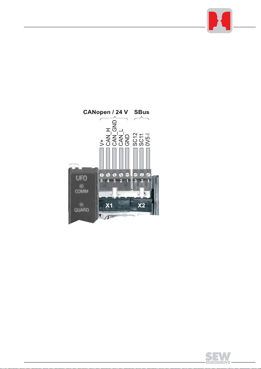
1.1 Front view
Unit Structure
Fig. 1: Arrangement of LEDs, connectors and DIP switches
X1 CANopen and electrical power supply
X2 SBus
X3 Diagnostic interface
S1 DIP switch
S2 DIP switch
COMM Communication on the CANopen interface
GUARD Status display for timeout on the CANopen bus
STATE CANopen operating status of the UFO11
BUS-F Bus fault on the CANopen interface
SYS-F System fault
USER Expert mode
4
05790AXX
Manual – UFO11A Fieldbus Interface
Page 5
Installation and Operation without a PC
Phone: 800.894.0412 - Fax: 888.723.4773 - Web: www.clrwtr.com - Email: info@clrwtr.com
2 Installation and Operation without a PC
2.1 Installation notes
Mounting
Pin assignment
The unit can be mounted using the pre-installed DIN rail mounting option or directly onto
a switch cabinet wall using the four holes integrated into the back wall of the housing.
Basically, there are no restrictions regarding positioning in relation to the inverters to be
connected (e.g. MOVITRAC
®
07). In laying out the system, consider the maximum cable
length and the fact that the gateway must be the first or last node on the system bus
(SBus).
2
Fig. 2: Pinout
Supply voltage
X1:5: V+
X1:1: GND
Manual – UFO11A Fieldbus Interface
CANopen
X1:4: CAN_H
X1:3: CAN_GND
X1:2: CAN_L
05789AXX
SBus
X2:3: SC12
X2:2: SC11
X2:1: 0V5-I
5
Page 6
2
Phone: 800.894.0412 - Fax: 888.723.4773 - Web: www.clrwtr.com - Email: info@clrwtr.com
Installation and Operation without a PC
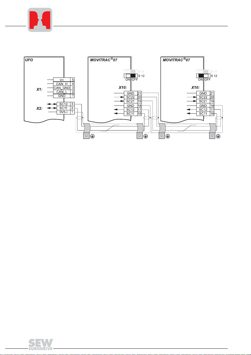
System bus
connection
Fig. 3: System bus connection
UFO11A
V+ = Supply voltage
CAN_H = CAN bus high
CAN_GND = CAN bus reference
CAN_L = CAN bus low
0V5-I = System bus reference
SC11 = System bus high
SC12 = System bus low
Please note:
• Use a 2-core twisted and shielded copper cable (data transmission cable with
• The permitted total cable length depends on the baud rate setting of the SBus:
05791AXX
MOVITRAC® 07
GND = System bus reference
SC22 = System bus outgoing low
SC21 = System bus outgoing high
SC12 = System bus incoming low
SC11 = System bus incoming high
S12 = System bus terminating resistor
braided copper shield). Connect the shield at either end to the electronics shield
clamp of MOVITRAC
®
07 or the UFO11A and also connect the ends of the shield to
GND/0V5-I. The cable must meet the following specifications (CAN bus or DeviceNet
cables are suitable, for example):
– Conductor cross section 0.75 mm
2
(AWG18)
– Cable resistance 120 Ω at 1 MHz
– Capacitance per unit length ≤ 40 pF/m (12 pF/ft) at 1 kHz
– 125 kbaud: 320 m (1056 ft)
– 250 kbaud: 160 m (528 ft)
– 500 kbaud: 80 m (264 ft)
– 1000 kbaud: 40 m (132 ft)
6
Manual – UFO11A Fieldbus Interface
Page 7

Installation and Operation without a PC
Phone: 800.894.0412 - Fax: 888.723.4773 - Web: www.clrwtr.com - Email: info@clrwtr.com
• Switch on the system bus terminating resistor (S12 = ON) of the node end of the
system bus. Switch off the terminating resistor on the other units (S12 = OFF). The
UFO11A gateway must always be the first or last node on the system bus. It has an
integrated terminating resistor.
• There must not be any potential difference between the units connected to the SBus.
Take suitable measures such as connecting each unit’s ground lug to a central
grounding point in the cabinet to avoid potential differences.
• Point-to-point cabling is not permitted.
2
Shielding and
routing of the bus
cables
The CANopen interface supports RS-485 transmission technology and requires the
cable type A to EN 50170 specified as the physical medium for CANopen. This cable
must be a shielded, twisted-pair two-core cable.
In practice, cables such as the Unitronic BUS CAN 2 × 2 × 0.22 made by Lapp have
proven effective even under harsh conditions. The CAN signals are carried along one
pair of conductors. The other pair of conductors is used for CAN ground and any supply
voltage which is also carried. Yellow – CAN high / Green – CAN low / Brown – CAN
GND.
This setup offers the advantage that the necessary compensating current of the bus
drivers does not have to be carried along the shield. As a result, no parasitic EMC
interference is carried into the shield and ultimately the electronics.
Having the bus cable correctly shielded cuts out parasitic interference which can occur
in an industrial environment. The following measures ensure the best possible shielding:
• Finger-tighten the retaining screws of plugs, modules and equipotential bonding
conductors.
• Use only connectors with a metal housing or a metallized housing.
• Maximize the contact area between the shield and the connector housing.
• Shield the bus cable on both ends.
• Do not route the signal and bus cables in parallel with the power cables (motor
leads); use separate cable ducts if possible.
• Use only grounded metal cable trays in industrial environments.
• Join the signal cables and the associated equipotential bonding together at closely
spaced intervals by the shortest route.
• Avoid using plug connections to extend bus cables.
• Route the bus cables closely adjacent to available grounding surfaces.
In the event of fluctuations in the ground potential, a compensating current may flow
along the shield which is connected at both ends and to the ground potential (PE). In this
case, make adequate provision for equipotential bonding in accordance with the
relevant VDE regulations.
Bus termination
Manual – UFO11A Fieldbus Interface
No bus termination is provided on the UFO electronics. External bus termination must
be used if the UFO module is used as the first or last unit in the CANopen branch. To do
this, connect the supplied 120 Ω resistor between CAN high and CAN low (terminals
X1:2 and X1:4) as well.
7
Page 8

2
Phone: 800.894.0412 - Fax: 888.723.4773 - Web: www.clrwtr.com - Email: info@clrwtr.com
Installation and Operation without a PC
2.2 Setting the inverter parameters (MOVITRAC® 07)
• Switch on the voltage supply for the UFO and all connected inverters.
• Set an individual SBus address (P813) on the inverters. Recommendation: Assign
the addresses starting from address 1 and working in ascending order according to
the arrangement of inverters in the switch cabinet. Do not assign address 0 since this
is used by the UFO.
• Set the setpoint source (P100) to SBus (value 10 on MOVITRAC
• Set the control signal source (P101) to SBus (value 3 on MOVITRAC
• Set the terminal assignment of the binary inputs (P60-). Set unrequired binary inputs
to "No function." For safety reasons, the inverter must be enabled on the terminal
side. Refer to the appropriate unit documentation for information about this. For
MOVITRAC
following assignment:
– DI01 CW/STOP (applied to 24 V, enable CW direction of rotation)
– DI02 CCW/STOP (no function)
– DI03 FIX SETPT SW.OV (not connected)
– DI04 n11/n21 (not connected)
– DI05 n12/n22 (not connected)
• Set the SBus timeout delay (P815) to a value other than 0, for example 1 s, to
activate the monitoring process.
• If necessary, change the default values of the process data assignments (P870 –
P875). This step must be performed before Autosetup (see Sec. "Autosetup").
®
07, parameter P60- can be set to the value 0. This corresponds to the
2.3 Autosetup
You can start up the UFO without a PC with the Autosetup function. It is activated with
the Autosetup DIP switch. Turning on the Autosetup DIP switch will execute the function
once. The function can be executed once again by turning the switch off and on again.
Upon activation of the Autosetup feature, the UFO automatically searches for inverters
on the lower-level SBus and indicates this activity with a brief blinking of the SYS-F LED.
Each drive inverter on the SBus must be assigned a unique SBus address (P813). To
avoid confusion with data assignments, it is recommended to assign the addresses from
address 1 and working in ascending order according to the arrangement of inverters in
the control cabinet. The process image on the fieldbus side will be extended by three
words for each located inverter. The SYS-FLT LED stays on if no drive inverters are
found. A maximum of eight inverters can be configured. Following the search, the UFO
cyclically exchanges three process data words with each connected drive inverter. The
process output data are collected from the fieldbus, divided into blocks of three and sent.
The process input data are read by the drive inverters, assembled and sent to the fieldbus master.
®
07).
®
07).
8
Manual – UFO11A Fieldbus Interface
Page 9

Installation and Operation without a PC
Phone: 800.894.0412 - Fax: 888.723.4773 - Web: www.clrwtr.com - Email: info@clrwtr.com
Autosetup has to be executed only once. The detected configuration will be saved in the
non-volatile memory. Important: Execute Autosetup again in case you change the
process data assignment of the drive inverters connected to the UFO, because the UFO
saves these values once only during Autosetup. Likewise, the process data
assignments of the connected drive inverters must not be altered dynamically either, for
example by an IPOS program, following Autosetup. Failure to comply with this
instruction could prevent a fault response if there is a fieldbus timeout.
2.4 Setting the UFO DIP switches
• For project planning, set an individual CANopen address using the DIP switches on
the UFO (see Sec. "DIP Switches"). Address 0 is not permitted in CANopen.
• Set the DIP switches for the number of process data items (see Sec. "DIP Switches").
The following applies: Number of process data items = Number of connected
inverters times 3.
• Set the DIP switch for the baud rate of the CANopen bus (see Sec. "DIP Switches").
Changes to the DIP switches do not come into effect until the UFO has been switched
off and on.
2
Manual – UFO11A Fieldbus Interface
9
Page 10

3
Phone: 800.894.0412 - Fax: 888.723.4773 - Web: www.clrwtr.com - Email: info@clrwtr.com
Installation and Operation with a PC
3 Installation and Operation with a PC
3.1 Installation notes
Mounting
Pin assignment
The unit can be mounted using the pre-installed DIN rail mounting option or directly onto
a switch cabinet wall using the four holes integrated into the back wall of the housing.
Basically, there are no restrictions regarding positioning in relation to the inverters to be
connected (e.g. MOVITRAC
length and the fact that the gateway must be the first or last node on the system bus
(SBus).
®
07). In laying out the system, consider the maximum cable
05789AXX
SBus
X2:3: SC12
X2:2: SC11
X2:1: 0V5-I
Manual – UFO11A Fieldbus Interface
10
Fig. 4: Pinout
Supply voltage
X1:5: 24 V
X1:1: 0 V
CANopen
DC
DC
X1:4: CAN H
X1:3: CAN GND
X1:2: CAN L
Page 11

System bus
Phone: 800.894.0412 - Fax: 888.723.4773 - Web: www.clrwtr.com - Email: info@clrwtr.com
connection
Installation and Operation with a PC
3
Fig. 5: System bus connection
UFO11A
V+ = Supply voltage
CAN_H = CAN bus high
CAN_GND = CAN bus reference
CAN_L = CAN bus low
0V5-I = System bus reference
SC11 = System bus high
SC12 = System bus low
Please note:
• Use a 2-core twisted and shielded copper cable (data transmission cable with
• The permitted total cable length depends on the baud rate setting of the SBus:
05095AXX
MOVITRAC® 07
GND = System bus reference
SC22 = System bus outgoing low
SC21 = System bus outgoing high
SC12 = System bus incoming low
SC11 = System bus incoming high
S12 = System bus terminating resistor
braided copper shield). Connect the shield at both ends to the electronics shield
clamp of MOVITRAC
®
07 or the UFO11A and ensure a large area of contact
between the shield and the clamp. Also connect the ends of the shield to GND/0V5I. The cable must meet the following specifications (CAN bus or DeviceNet cables
are suitable):
– Core cross section 0.75 mm
2
(AWG18)
– Cable resistance 120 Ω at 1 MHz
– Capacitance per unit length ≤ 40 pF/m (12 pF/ft) at 1 kHz
– 125 kbaud: 320 m (1056 ft)
– 250 kbaud: 160 m (528 ft)
– 500 kbaud: 80 m (264 ft)
– 1000 kbaud: 40 m (132 ft)
Manual – UFO11A Fieldbus Interface
11
Page 12

3
Phone: 800.894.0412 - Fax: 888.723.4773 - Web: www.clrwtr.com - Email: info@clrwtr.com
Installation and Operation with a PC
• Switch on the system bus terminating resistor (S12 = ON) at the end of the system
bus. Switch off the terminating resistor on the other units (S12 = OFF). The UFO11A
gateway must always be the first or last node on the system bus. It has an integrated
terminating resistor.
• There must not be any potential difference between the units connected to the SBus.
Take suitable measures such as connecting each unit’s ground lug to a central
grounding point in the cabinet to avoid potential differences.
• Point-to-point cabling is not permitted.
Shielding and
routing of the bus
cables
The CANopen interface supports RS-485 transmission technology and requires the
cable type A to EN 50170 specified as the physical medium for CANopen. This cable
must be a shielded, twisted-pair two-core cable.
In practice, cables such as the Unitronic BUS CAN 2 × 2 × 0.22 made by Lapp have
proven effective even under harsh conditions. The CAN signals are carried along one
pair of conductors. The other pair of conductors is used for CAN ground and any supply
voltage which is also carried. Yellow – CAN high / Green – CAN low / Brown – CAN
GND.
This setup offers the advantage that the necessary compensating current of the bus
drivers does not have to be carried along the shield. As a result, no parasitic EMC
interference is carried into the shield and ultimately the electronics.
Having the bus cable correctly shielded cuts out parasitic interference which can occur
in an industrial environment. The following measures ensure the best possible shielding:
• Finger-tighten the retaining screws of plugs, modules and equipotential bonding
conductors.
• Use only connectors with a metal housing or a metallized housing.
• Maximize the contact area between the shield and the connector housing.
• Shield the bus cable on both ends.
• Do not route the signal and bus cables in parallel with the power cables (motor
leads); use separate cable ducts if possible.
• Use only grounded metal cable trays in industrial environments.
• Join the signal cables and the associated equipotential bonding together at closely
spaced intervals by the shortest route.
• Avoid using plug connections to extend bus cables.
• Route the bus cables closely adjacent to available grounding surfaces.
In the event of fluctuations in the ground potential, a compensating current may flow
along the shield which is connected at both ends and to the ground potential (PE). In this
case, make adequate provision for equipotential bonding in accordance with the
relevant VDE regulations.
Bus termination
12
No bus termination is provided on the UFO electronics. External bus termination must
be used if the UFO module is used as the first or last unit in the CANopen branch. To do
this, connect the supplied 120 Ω resistor between CAN high and CAN low (terminals
X1:2 and X1:4) as well.
Manual – UFO11A Fieldbus Interface
Page 13

Installation and Operation with a PC
Phone: 800.894.0412 - Fax: 888.723.4773 - Web: www.clrwtr.com - Email: info@clrwtr.com
3
UWS21A
• The UFO is equipped with a 4-pol phone jack on its front panel. The UWS21A option
with part no. 8230773 establishes the connection to a COM interface on your PC.
Connect the desired COM of the PC with the UWS21A via the enclosed serial cable.
Connect the UWS21A to the UFO using the supplied phone cable.
Fig. 6: UWS connection
3.2 Setting the inverter parameters (MOVITRAC® 07)
• Switch on the voltage supply for the UFO and all connected inverters.
• Set an individual SBus address (P813) on the inverters. Recommendation: Assign
the addresses starting from address 1 and working in ascending order according to
the arrangement of inverters in the switch cabinet.
05901AXX
Do not assign address 0 since this is used by the UFO!
Manual – UFO11A Fieldbus Interface
13
Page 14

3
Phone: 800.894.0412 - Fax: 888.723.4773 - Web: www.clrwtr.com - Email: info@clrwtr.com
3.3 Startup software
Installation and Operation with a PC
• Install the MOVITOOLS® software package on your PC.
• Start the software. Select the COM port to which the UFO is connected and press the
"Update" button. The UFO should appear at address 0 and the connected inverters
on the following addresses. In case you do not see an entry in the window, please
check the COM interface and the connection via the UWS21. If you only see the UFO
as an entry in the window, please check the SBus cabling and the terminating
resistors.
• Select the UFO and start the startup software for the fieldbus gateway.
• Select the menu item "New configuration of fieldbus node."
• Enter your project path and name. -> Next
• Press the "Update" button. You should now see all inverters connected to the UFO.
You can customize the configuration with the "Insert", "Edit" and "Delete" buttons.
-> Next
• Press the "Autoconfiguration" button. You will now see the process image for the
UFO in your control. The process data length is displayed at the bottom. This value
is important for configuration of the fieldbus master. -> Next
• Save the project data and click the "Download" button. If you experience problems
with the download, you have probably set the DIP switch to AUTOSETUP. You need
to turn off the autosetup feature when configuring with a PC.
• You can see the data being exchanged between fieldbus master and UFO with the
process data monitor.
• You will have to enable the unit via the terminals to control the inverters via fieldbus.
You have already connected the terminals DI01 and DI02 (MOVITRAC
the first inverter with address 1 in the window "Connected units" to check the pinout.
• Repeat this step for all inverters listed in the window "Connected units."
®
07). Select
3.4 Setting the UFO DIP switches
• For project planning, set an individual CANopen address using the DIP switches on
the UFO (see Sec. "DIP Switches"). Address 0 is not permitted in CANopen.
• Set the DIP switches for the number of process data items (see Sec. "DIP Switches").
The following applies: Number of process data items = Number of connected
inverters times 3.
• Set the DIP switch for the baud rate of the CANopen bus (see Sec. "DIP Switches").
Changes to the DIP switches do not come into effect until the UFO has been switched
off and on.
14
Manual – UFO11A Fieldbus Interface
Page 15

4 CANopen Interface
Phone: 800.894.0412 - Fax: 888.723.4773 - Web: www.clrwtr.com - Email: info@clrwtr.com
4.1 Configuring the CANopen interface
General features of the CANopen interface of the UFO:
• 0 to 8 RX PDOs
• 0 to 8 TX PDOs
• Various transmission modes for the PDOs
• Length of the PDOs can be configured dynamically
•1 SDO
• Emergency message
• COB IDs for SYNC, emergency and PDOs can be configured dynamically.
• Heartbeat producer & consumer
• Guarding protocol
CANopen Interface
4
Unit states and
NMT services
The UFO supports what is referred to as the "minimum capability device". This means
the following states are supported: "pre-operational", "operational" and "prepared". In
"pre-operational" status, the device can only communicate via SDOs (see also Sec.
"CANopen Interface" / "Parameter access via SDOs"). PDOs and SDOs can be
exchanged in "operational" status; neither SDOs nor PDOs can be exchanged in
"stopped" status.
Following switch-on, the CANopen option card is always automatically in the "preoperational" status.
Fig. 7: Status diagram for CANopen devices
05772AXX
Manual – UFO11A Fieldbus Interface
15
Page 16

4
Phone: 800.894.0412 - Fax: 888.723.4773 - Web: www.clrwtr.com - Email: info@clrwtr.com
CANopen Interface
The states can be changed at any time by services referred to as NMT services.
The possible commands in this case are:
• (6) Node_Start indication
• (7) Node_Stop indication
• (8) Enter_Pre-Operational_State indication
• (10) Reset_Node indication: This command resets the entire inverter and the UFO
activates the default settings in the object list.
• (11) Reset_Communication: This command triggers a reset of the communication
parameters in the object list.
• (12) Initialization complete – automatically changes to "pre-operational"
The CAN respective telegrams have the following structure:
NMT service COB ID Byte 1 Byte 2
Node_Start 0x0000 0x01 Node ID
Node_Stop 0x0000 0x02 Node ID
Enter_Pre-Operational_State 0x0000 0x80 Node ID
Reset_Node 0x0000 0x81 Node ID
Reset_Communication 0x0000 0x82 Node ID
In this case, node ID corresponds to the address set in the DIP switches (see Sec. "DIP
Switches"). In addition, the value "0" is permitted for the node ID here; in this case, all
CANopen devices are addressed.
NMT services are not confirmed by the slave.
Process data
exchange
16
Up to 8 inverters can be connected to the gateway. A maximum of 3 process words
(process output data items, PO for short) are sent from the UFO to each inverter and 3
process input words (PI for short) are sent from each inverter to the UFO. This means
the UFO is provided with a 24 word process data buffer (48 bytes) for the POs and a 24
word buffer for the PIs.
The buffer for the POs is located at index 15800 ... 15823 (subindex 0) and the buffer
for the PIs at index 15900 ... 15923 (subindex 0).
RX PDOs can be written to the PO buffer by the control. A maximum of 4 words can be
transmitted by each PDO in the CANopen profile. This means at least 6 RX PDOs are
necessary to transmit 24 process data items from the control to the UFO.
However, a maximum of 4 default RX PDOs are defined in CANopen DS301 V4.02. You
can assign the COB IDs of the PDOs dynamically from the control to avoid conflicts with
the COB IDs on the CANopen bus.
Manual – UFO11A Fieldbus Interface
Page 17

CANopen Interface
Phone: 800.894.0412 - Fax: 888.723.4773 - Web: www.clrwtr.com - Email: info@clrwtr.com
In addition, it may be desirable under special circumstances for the 24 process data
items to be transmitted with mutual or partially mutual consistency. Consistent
transmission can be achieved using a SYNC telegram and by configuring the
corresponding RX PDOs to "SYNC" transmission mode.
It is possible to send process data subject to event control, which means only whenever
they have changed. This is done to reduce bus traffic and to avoid having to transmit 24
PDs cyclically.
Up to 8 RX PDOs are provided in the UFO to transmit the POs for each connected
inverter in a separate RX PDO. The length of an RX PDO can be adapted if only 1 PO
(control word) is sent to the inverter instead of 3 POs.
It goes without saying that the TX PDOs can be configured in the same way as the RX
PDOs described above.
4
Configuration of
the COB IDs
In its initializing status, the UFO defines the COB IDs according to the settings of the DIP
switches (see Sec. "DIP Switches").
If more than 4 PDOs are activated with the DIP switches, the UFO also uses the default
COB IDs of the CANopen slave address 64 + (own slave address).
If only slaves with addresses < 65 are connected to the CANopen bus, no bus conflicts
can occur, even when 8 RX and 8 TX PDOs are used. If the system contains slaves with
addresses > 64, an individual check must be made to see whether the COB IDs need to
be changed by the CANopen master.
The COB IDs should be changed in the pre-operational unit status (see Sec. "CANopen
Interface"). Although it is also possible to change the COB IDs in the operational status,
the CAN controller is temporarily separated from the bus. This means process data
losses may occur in the operational status.
The COB IDs for TX PDO1..8 can be changed using object 1800(hex) – 1807(hex),
subindex 1.
The COB IDs for RX PDO1..8 can be changed using object 1400(hex) – 1407(hex),
subindex 1. This is a 32-bit word. Its basic structure is explained in the tables "Structure
of the PDO COB ID entry" and "Description of the PDO COB ID entry."
Identifier range 0 ... 28 can only be changed if bit 31 is set at the same time (COB ID
invalid). New values are only accepted in the identifier range if they have an 11-bit ID
(i.e. bit 29 is never allowed to be set) and if the ID has not already been assigned to
another PDO or the emergency object (see Sec. "CANopen Interface" / "Emergency
object").
In TX PDOs, bit 30 (RTR not allowed) must always be 0 and it must always be set in RX
PDOs.
Manual – UFO11A Fieldbus Interface
17
Page 18

4
Phone: 800.894.0412 - Fax: 888.723.4773 - Web: www.clrwtr.com - Email: info@clrwtr.com
Structure of the
PDO COB ID entry
Description of the
PDO COB ID entry
CANopen Interface
UNSIGNED32
MSB LSB
Bits 31 30 29 28 ... 11 10 ... 0
11-bit ID 0/1 0/1 0 0 0 0 0 0 0 0 0 0 0 0 0 0 0 0 0 0 0 11-bit identifier
29-bit ID 0/1 0/1 1 29-bit identifier
Bits Value Meaning
31 (MSB 0 PDO exists / is valid
1 PDO does not exist / is not valid
30 0 RTR allowed in this PDO
1 RTR not allowed in this PDO
29 0 11-bit ID (CAN 2.0A)
1 29-bit ID (CAN 2.0B)
28 ... 11 0 If bit 29 = 0
X If bit 29 = 1: Bits 28 ... 11 of 29-bit COB ID
10 ... 0 (LSB) X Bits 10 ... 0 of COB ID
18
Manual – UFO11A Fieldbus Interface
Page 19

Changing the
Phone: 800.894.0412 - Fax: 888.723.4773 - Web: www.clrwtr.com - Email: info@clrwtr.com
PDO length
CANopen Interface
4
Fig. 8: Standard division of the UFO process data buffer
In initializing status, the UFO specifies the mapping and the length of all TX and RX
PDOs as 3 process data items.
Manual – UFO11A Fieldbus Interface
05773AXX
19
Page 20

4
Phone: 800.894.0412 - Fax: 888.723.4773 - Web: www.clrwtr.com - Email: info@clrwtr.com
CANopen Interface
The number of process data items in the PDOs should be changed in the preoperational unit status (see Sec. "CANopen Interface"). Although it is also possible to
make such changes in the operational status, the CAN controller is temporarily
separated from the bus. This means process data losses may occur in the operational
status.
Fig. 8 shows the classic division of the process data buffer in the UFO following an
Autosetup (see Sec. "Installation and Operation without a PC" / "Autosetup"). The
number of process data items which are transmitted in a PDO and the number of
process data items which are transmitted to the corresponding inverter via the SBus are
completely independent of one another. When Autosetup is selected, 3 POs and 3 PIs
are always provided on the SBus for each connected inverter. The UFx Configurator
makes it possible to set other configurations (see Sec. "Using the Interface"). As a rule,
this configuration will enable 90 % of all applications to work satisfactorily.
Fig. 9 illustrates how a control word and the speed are transmitted in an RX PDO using
PDO1. In a second RX PDO, the ramp for the inverter with SBus address 2 is
transmitted. This method allows a reduced bus traffic if the ramp is to be transmitted
much less frequently than the control word and the setpoint speed.
Fig. 9: 2 PDOs for 1 MOVITRAC® 07
20
Manual – UFO11A Fieldbus Interface
05774AXX
Page 21

CANopen Interface
Phone: 800.894.0412 - Fax: 888.723.4773 - Web: www.clrwtr.com - Email: info@clrwtr.com
Fig. 10 shows a possible configuration in which only two or one process data items are
transmitted via the SBus rather than three. RX PDO1 was configured with two process
data items and RX PDO2 with one process data item to give a consistent and logical
assignment to PDOs.
4
Transmission
mode
TX PDO
Fig. 10: Consistent assignment of PDOs to the individual inverters
The number of process data items transferred with the individual PDOs is defined for RX
PDO1 ... 8 by object 1600(hex) ... 1607(hex), subindex 0 and for TX PDO1 ... 8 with
object 1A00(hex) ... 1A07(hex), subindex 0. Possible values are in the range 0 ... 4. 0
corresponds to a PDO which does not transmit any process data, 4 corresponds to a
PDO which transmits 4 process data items (8 bytes). The important peripheral condition
in this case is that the total of all process data transmitted in RX PDOs is not to exceed
24 and the total of all process data transmitted in the TX PDOs is not to exceed 24. The
mapping is automatically recalculated and defined by the UFO. The UFO always
assumes that RX PDO1 ... 8 are mapped in succession into the PO buffer and TX PDO1
... 8 are mapped in succession into the PI buffer.
It is possible to select from various transmission modes for each TX PDO and for each
RX PDO:
The transmission modes for TX PDO1 ... 8 can be changed using object 1800(hex) ...
1807(hex), subindex 2. This is an 8-bit value.
• Event-driven and synchronous (value 0): The corresponding TX PDO is always sent
following the next SYNC pulse whenever a process data item has changed.
05775AXX
Manual – UFO11A Fieldbus Interface
21
Page 22

4
Phone: 800.894.0412 - Fax: 888.723.4773 - Web: www.clrwtr.com - Email: info@clrwtr.com
CANopen Interface
• Cyclical and synchronous (value 1 ... 240): After every 1st ... 240th SYNC pulse
(depending on the value), the TX PDO is sent regardless of whether the content of
the TX PDOs has changed or not. Every PDO has transmission mode = 1 after
leaving initialized status.
• Proprietary (value 254): For this mode, the corresponding RX PDO must also be set
to transmission mode 254. The TX PDO is always sent whenever the corresponding
RX PDO is received. In this case, the process data takeover is completely
asynchronous, i.e. unrelated to the SYNC pulses. Example: RX PDO2 and TX PDO2
have transmission mode 254. A TX PDO2 is sent immediately after a valid RX PDO2
is received (valid means the length is not too short).
• Event-driven and asynchronous (value 255): Whenever a value of the TX PDO
changes, this is sent by the UFO. Warning: This setting results in very considerable
bus traffic if the TX PDO is used for sending speed, current, position or other rapidly
changing parameters. The inhibit time can be used for restricting the bus traffic
deterministically for such TX PDOs.
Transmission modes 241 ... 253 are reserved and cannot be selected.
See Sec. "CANopen Interface" / "SYNC object" for information about the SYNC pulse.
The default setting is 1 (synchronous on each SYNC pulse).
RX PDO
The transmission modes for RX PDO1 ... 8 can be changed using object 1400(hex) ...
1407(hex), subindex 2. This is an 8-bit value.
• Synchronous (value 0 ... 240): The data of the RX PDO are transferred into the PO
buffer of the UFO when the next SYNC pulse is received (it does not matter whether
the value is 0 or 240). This transmission process allows several PDOs to be sent from
the master to the UFO and then transferred into the PO buffer of the UFO using a
SYNC pulse at the same time and with mutual consistency.
• Proprietary (value 254): For this mode, the corresponding RX PDO must also be set
to transmission mode 254. The TX PDO is always sent whenever the corresponding
RX PDO is received. In this case, the process data takeover is completely
asynchronous, i.e. unrelated to the SYNC pulses. Example: RX PDO2 and TX PDO2
have transmission mode 254. A TX PDO2 is sent immediately after a valid RX PDO2
is received (valid means the length is not too short).
• Event-driven and asynchronous (value 255): Whenever an RX PDO arrives, it is
always accepted and passed on.
Transmission modes 241 ... 253 are reserved and cannot be selected.
See Sec. "CANopen Interface" / "SYNC object" for information about the SYNC pulse.
The default setting is 1 (synchronous on each SYNC pulse).
22
Manual – UFO11A Fieldbus Interface
Page 23

CANopen Interface
Phone: 800.894.0412 - Fax: 888.723.4773 - Web: www.clrwtr.com - Email: info@clrwtr.com
4
Inhibit time
4.2 SYNC object
Changing the
COB ID of the
SYNC object
Structure of the
SYNC COB ID
entry
The inhibit time is a blocking time for TX PDOs. The inhibit time for a TX PDO starts after
the object is sent. The object is not allowed to be sent again on the CANopen bus until
the inhibit time has elapsed. The inhibit time is entered in 0.0001 s, i.e. 10000
corresponds to 1 s. The maximum inhibit time is 6.5535 s.
The UFO processes inhibit times with a resolution of 1.0 ms, i.e. the value 15
(corresponding to an inhibit time of 1.5 ms) is treated as 2 ms.
The inhibit time cannot be changed unless the corresponding PDO is marked as
"invalid" (index 1800(hex) ... 1807(hex), subindex 1, bit 31 = 1, see Sec. "Configuration
of the COB IDs").
The SYNC object transfers process data of several PDOs into the UFO data buffer or
sends them in a mutually consistent way at a defined point in time. All PDOs to be
synchronized with the SYNC object have to be operated in transmission mode 0 ... 240.
If the transmission mode of a TX PDO is 4, the UFO sends this TX PDO after every 4th
SYNC pulse. The situation is different with RX PDOs: These accept the PDO data on
every SYNC pulse.
In initializing status, the UFO defines the COB ID of the SYNC object as 0080 hex.
The COB ID should be changed in the pre-operational unit status (see Sec. "CANopen
Interface"). Although it is also possible change the COB ID in the operational status, the
CAN controller is temporarily separated from the bus. This means process data losses
may occur in the operational status.
The UFO is only a SYNC consumer and only works with 11-bit COB IDs. Consequently,
bit 30 and bit 29 must always be 0. The structure of the COB ID and the meaning of the
individual bits are explained in the tables "Structure of the SYNC COB ID entry" and
"Description of the SYNC COB ID entry".
The COB ID is addressed as unsigned long via index 1005hex, subindex 0.
UNSIGNED32
MSB LSB
Bits 31 30 29 28 ... 11 10 ... 0
11-bit ID X 0/1 0 0 0 0 0 0 0 0 0 0 0 0 0 0 0 0 0 0 0 11-bit identifier
29-bit ID X 0/1 1 29-bit identifier
Manual – UFO11A Fieldbus Interface
23
Page 24

4
Phone: 800.894.0412 - Fax: 888.723.4773 - Web: www.clrwtr.com - Email: info@clrwtr.com
CANopen Interface
Description of the
SYNC COB ID
entry
4.3 Emergency object
Bits Value Meaning
31 (MSB) X No influence
30 0 Unit does not generate SYNC message
29 0 11-bit ID (CAN 2.0A)
28 ... 11 0 If bit 29 = 0
10 ... 0 (LSB) X Bits 10 ... 0 of SYNC COB ID
1 Unit does generate SYNC message
1 29-bit ID (CAN 2.0B)
X If bit 29 = 1: Bits 28 ... 11 of 29-bit SYNC COB ID
The emergency object is always sent once by the UFO when a fault is detected and
once again when this fault is no longer present.
The UFO sends an EMCY object in response to the following faults:
• An inverter sets the error bit in its status word.
Byte 1 Byte 2 Byte 3 Byte 4 Byte 5 Byte 6 Byte 7 Byte 8
10hex FFhex Error register
(object 1000hex)
0 Status word 1 of
the inverter, low
Status word 1 of
the inverter,
high
0 SBus addr. of
the inverter
• The UFO sets the error bit in its status word.
Byte 1 Byte 2 Byte 3 Byte 4 Byte 5 Byte 6 Byte 7 Byte 8
0 FFhex Error register
(object 1000hex)
0 Status word 1 of
the UFO, low
Status word 1 of
the UFO, high
0 SBus addr. of
the inverter
• The inverter is only running in 24 V backup mode, there is no voltage for the rotating
field.
Byte 1 Byte 2 Byte 3 Byte 4 Byte 5 Byte 6 Byte 7 Byte 8
0 31hex Error register
(object 1000hex)
0000SBus addr. of
• The CAN controller has lost telegrams from the CANopen bus because the receive
queue has overrun.
Byte 1 Byte 2 Byte 3 Byte 4 Byte 5 Byte 6 Byte 7 Byte 8
24
10hex 81hex Error register
(object 1000hex)
00000
Manual – UFO11A Fieldbus Interface
the inverter
Page 25

COB ID of the
Phone: 800.894.0412 - Fax: 888.723.4773 - Web: www.clrwtr.com - Email: info@clrwtr.com
emergency object
Structure of the
identifier entry
EMCY
Description of the
SYNC COB ID
entry
CANopen Interface
• The CAN controller is in the error-passive status (see Sec. "LEDs" / "BUS-F LED").
Byte 1 Byte 2 Byte 3 Byte 4 Byte 5 Byte 6 Byte 7 Byte 8
20hex 81hex Error register
(object 1000hex)
• The CAN controller was in the bus off status (see Sec. "LEDs" / "BUS-F LED").
Byte 1 Byte 2 Byte 3 Byte 4 Byte 5 Byte 6 Byte 7 Byte 8
40hex 81hex Error register
(object 1000hex)
• The lifeguarding protocol was activated but not served within the timeout time.
Byte 1 Byte 2 Byte 3 Byte 4 Byte 5 Byte 6 Byte 7 Byte 8
30hex 81hex Error register
Bits 31 30 29 28 ... 11 10 ... 0
11-bit ID 0/1 0 0 0 0 0 0 0 0 0 0 0 0 0 0 0 0 0 0 0 0 11-bit identifier
29-bit ID 0/1 0 1 29-bit identifier
Bits Value Meaning
31 (MSB 0 EMCY exists / is valid
30 0 reserved (always 0)
29 0 11-bit ID (CAN 2.0A)
28 ... 11 0 If bit 29 = 0
10 ... 0 (LSB) X Bits 10 ... 0 of COB ID
(object 1000hex)
UNSIGNED32
MSB LSB
1 EMCY does not exist / is not valid
1 29-bit ID (CAN 2.0B)
X If bit 29 = 1: Bits 28 ... 11 of 29-bit COB ID
00000
00000
00000
4
Manual – UFO11A Fieldbus Interface
25
Page 26

4
Phone: 800.894.0412 - Fax: 888.723.4773 - Web: www.clrwtr.com - Email: info@clrwtr.com
CANopen Interface
In initializing status, the UFO defines the COB ID of the EMCY object as 0080hex +
slave address.
The COB ID should be changed in the pre-operational unit status (see Sec. "CANopen
Interface"). Although it is also possible to change the COB ID in the operational status,
the CAN controller is temporarily separated from the bus. This means process data
losses may occur in the operational status.
Bit 29 must always be 0 because the UFO only works with 11-bit COB IDs. The structure
of the COB ID and the meaning of the individual bits are explained in the tables
"Structure of the EMCY identifier entry" and "Description of the EMCY COB ID entry".
If the UFO is not to send any EMCY object, the EMCY object can be deactivated by
setting bit 31 to 1.
The COB ID is addressed as unsigned long via index 1014hex, subindex 0.
Inhibit time of the
EMCY object
The inhibit time of the emergency object on the CANopen bus is specified as
unsigned16 (2 bytes) via index 1015hex, subindex 0. This value is 0 when the UFO exits
initialized status, i.e. there is no inhibit time.
The inhibit time is defined as a multiple of 0.0001 s, i.e. the value 3000 corresponds to
an inhibit time of 300 ms.
4.4 Guarding and heartbeat
Lifetime
The UFO supports two kinds of timeout monitoring (nodeguarding). First, the network
master can check whether the individual nodes are still ready to operate. To do this, a
nodeguarding object with RTR bit set must be sent to the nodes (example for node ID
"3"):
If the node is ready, it responds with a corresponding nodeguarding object which returns
the current readiness status and a toggle bit:
The toggle bit changes between 0 and 1 with every telegram. The network master can
use the response to determine whether the CANopen participants are still in their
original status or whether the status has changed due to a fault.
In initializing status, the UFO defines the COB ID for nodeguarding as 0700hex +
CANopen address.
In the second type of lifeguarding, the CANopen slaves check their NMT master. It is
possible to set a timeout time for this in milliseconds using the indices 0x100C ("guard
time") and 0x100D ("lifetime factor"). This timeout time is calculated as the product of
lifetime factor and guard time. Timeout times shorter than 5 ms are rejected. The second
type of nodeguarding is only active if a timeout time other than 0 is set (i.e. lifetime factor
0 and guard time 0). All process data words in the UFO are set to zero if no node event
is triggered by the master within the timeout time.
26
Manual – UFO11A Fieldbus Interface
Page 27

CANopen Interface
Phone: 800.894.0412 - Fax: 888.723.4773 - Web: www.clrwtr.com - Email: info@clrwtr.com
Refer to the appropriate operating instructions to see how the inverters connected to the
UFO via the SBus react to zero value setpoints and control words. Also, an
EMERGENCY object is placed on the CAN bus.
The GUARD LED lights up with a steady light to indicate that nodeguarding has been
activated.
The timeout time set by the control can be read out from P819 using the diagnostic
interface and MOVITOOLS. However, it is not to be changed using MOVITOOLS, but
instead only by the control using CANopen objects 0x100C and 0x100D:
Nodeguarding is active in all operating states from the first time a node is received from
the master.
4
Heartbeat
The UFO is a heartbeat producer. The time interval in which heartbeats are produced
can be set using index 1017hex, subindex 0 by means of an unsigned16 value. This
value corresponds to the heartbeat in ms, i.e. 3000 means that a heartbeat is sent every
3 s. The default value after exiting initialized status is 0, i.e. the heartbeat is deactivated.
If the guarding protocol is active, simultaneous use of the heartbeat protocol is not
allowed.
The UFO can monitor another heartbeat producer at the same time. An unsigned32
value in index 1016hex, subindex 1 sets the node to be monitored and the monitoring
time.
ID Byte 1 Byte 2 Byte 3 Byte 4 Byte 5 Byte 6 Byte 7 Byte 8
0x600 +
NodeID =
0x603
ID for SDO Expedited
0x423 0x16 0x10 0x01 Time in ms 0x01 –
Index
Index
Sub-
upload
low
high
index
Time low Time
high
0x7F
Nodes Re-
0x00
served
The monitoring time must have a larger value than the time interval set for the heartbeat
on the monitored node. If the heartbeat protocol is active then simultaneous use of the
lifetime mechanism is not allowed.
Manual – UFO11A Fieldbus Interface
27
Page 28

4
Phone: 800.894.0412 - Fax: 888.723.4773 - Web: www.clrwtr.com - Email: info@clrwtr.com
CANopen Interface
4.5 Parameter access via SDOs
SDOs and their
services
Example: "Device
type" read access
SDOs (service data objects) are used for setting parameters and reading out the
configuration. These SDOs are capable of transmitting large volumes of data, but they
are relatively slow. The following services can be applied to the SDOs in order to send
SDOs from or to the UFO:
• Multiplexed download domain (write access)
• Initiate domain download protocol
• Multiplexed upload domain (read access)
• Initiate domain upload pro tocol
• Abort domain transfer (for any protocol errors that may occur)
The
normal transfer
others are uploaded using the
The response time to a download or upload is not specified and also depends on the
system load, i.e. the bus traffic and the number of incoming PDOs.
Refer to Sec. "Object List" and the MOVIDRIVE
parameters, their indices and subindices.
In this example, a read access is made to the "Device type" entry in the unit with
CANopen address = 3 set on the DIP switches:
ID Byte 1 Byte 2 Byte 3 Byte 4 Byte 5 Byte 6 Byte 7 Byte 8
0x600 +
NodeID =
0x603
ID for SDO Expedited
The control must send an "initiate multiplexed upload domain" protocol for read access.
This protocol provides for all CAN telegrams being 8 bytes long.
The option card responds with:
ID Byte 1 Byte 2 Byte 3 Byte 4 Byte 5 Byte 6 Byte 7 Byte 8
0x580 +
NodeID =
0x583
ID for SDO Expedited
1) This value only applies to the printed telegram. This value may change depending on the data type in the
case of other indices, see CANopen DS301.
• Expedited transfer
• Normal transfer (data block length > 4 bytes)
• Expedited transfer
• Normal transfer (data block length > 4 bytes)
is only implemented for uploading objects 0x1008 – 0x100A; all
expedited transfer
0x40 0x00 0x10 0x00 0x00 0x00 0x00 0x00
upload
0x43
upload
Index low Index high Subindex Value unimportant
1)
0x00 0x10 0x00 0x2D 0x01 0x00 0x00
Index
Index
low
high
because they are 4 bytes long at most.
®
Fieldbus Unit Profile for the
Sub-
Re-
Re-
index
sponse
low
sponse
Response
Response
high
28
Manual – UFO11A Fieldbus Interface
Page 29

CANopen Interface
Phone: 800.894.0412 - Fax: 888.723.4773 - Web: www.clrwtr.com - Email: info@clrwtr.com
4
Example: Write
access
Incorrect
performance of
service
A similar example is the write access to index 0x100C, subindex 0x00 (guard time). This
entry is set to the value 10000 ms (0x2710)
The control sends an "expedited download" request first:
ID Byte 1 Byte 2 Byte 3 Byte 4 Byte 5 Byte 6 Byte 7 Byte 8
0x600 +
NodeID =
0x603
ID for SDO Expedited
1) This value only applies to the printed telegram. This value may change depending on the data type in the
case of other indices, see CANopen DS301.
1)
0x2B
download
0x0C 0x10 0x00 0x10 0x27 0x00 0x00
Index
Index
Sub-
Val ue
low
high
index
low
Val ue
high
Filler
byte
Filler
byte
The CANopen option card responds if implementation was successful (the CANopen
option card checks the index, subindex, write permission, data type and, if necessary,
whether the sent value is permitted):
ID Byte 1 Byte 2 Byte 3 Byte 4 Byte 5 Byte 6 Byte 7 Byte 8
0x580 +
NodeID =
0x583
ID for SDO Expedited
1) This value only applies to the printed telegram. This value may change depending on the data type in the
case of other indices, see CANopen DS301.
1)
0x60
download
0x00 0x10 0x00 0x00 0x00 0x00 0x00
Index
Index
Sub-
low
high
index
Value unimportant
The DFO11A sends an abort telegram in case of a fault. The abort telegram contains an
error code which describes the cause of the fault.
ID Byte 1 Byte 2 Byte 3 Byte 4 Byte 5 Byte 6 Byte 7 Byte 8
0x580 +
NodeID =
0x583
ID for SDO SDO abort Index
0x80 0x00 0x10 0x00
Index
high
Subindex
low
Add.
code low
Add. code
high
Error
code
Error
class
SEW-specific fault codes are described in [Inverter parameter settings] / [Return codes
for parameterization] of the MOVIDRIVE
®
Fieldbus Unit Profile. All other fault codes are
specified in the CANopen Communication Profile DS301, Sec. 9.2.2.
Access to SEW
unit parameters
The UFO parameters can be accessed using parameter access (from index 206Chex)
with subindex 0. The parameters of the inverters connected via the SBus can be
accessed using parameter access (from index 206Chex) with subindex ≠ 0. In this case,
the subindex should be set to the same value as the SBus address of the connected
inverter.
Example: Access index 8300, subindex 0 to read the software version of the UFO.
Access index 8300, subindex 2 to read the software version of the top MOVITRAC
in Fig. 8.
Manual – UFO11A Fieldbus Interface
®
07
29
Page 30

5
Phone: 800.894.0412 - Fax: 888.723.4773 - Web: www.clrwtr.com - Email: info@clrwtr.com
Error Response
5 Error Response
5.1 Fieldbus timeout
5.2 SBus timeout
5.3 Unit errors
In case the the timeout monitoring has been set and activated for the CANopen fieldbus,
switching off the fieldbus master or a wire break in the fieldbus cabling leads to a fieldbus
timeout in the UFO. The connected drive inverters are set to a safe status by zeros being
sent on the process output data. This corresponds to a rapid stop on control word 1. The
fieldbus timeout error is self-resetting, meaning the drive inverters will begin receiving
the current process output data from the master immediately after fieldbus communication is re-established. This error response can be deactivated using P831 on the UFO.
If one or more inverters on the Sbus can no longer be addressed by the UFO, the UFO
enters error code 91, "System error," in status word 1 of the corresponding drive inverter. The SYS-F LED lights up and the error is also displayed via the diagnostic interface.
P815 SBus timeout delay must be set to a value other than 0 on the drive inverter if it is
to stop. The error is self-resetting on the UFO, meaning the current process data are exchanged again immediately after communication resumes.
UFO fieldbus interfaces detect a range of hardware defects and respond with an inhibit
condition. Refer to the list of errors for the exact error responses and measures to remedy the problem. A hardware defect means error 91 is entered in the process input data
of the fieldbus in status word 1 of all drive inverters. The SYS-F LED on the UFO then
flashes evenly. The exact error code is displayed in the status of the UFO using the diagnostic interface of MOVITOOLS.
30
Manual – UFO11A Fieldbus Interface
Page 31

6LEDs
Phone: 800.894.0412 - Fax: 888.723.4773 - Web: www.clrwtr.com - Email: info@clrwtr.com
6.1 COMM LED
6.2 GUARD LED
LEDs
The UFO CANopen interface has 6 diagnostic LEDs:
• "COMM" LED (green) for displaying module communication
• "LIFE" LED (green/red) for displaying the fieldbus timeouts
• "STATE" LED (green) for displaying the UFO module status
• "BUS-F" LED (red) for displaying bus faults
• "SYS-F" LED (red) for displaying system faults and operating conditions of the UFO
• "USER" LED (green) for application-specific diagnostics in expert mode
The COMM LED always flashes briefly whenever the UFO has sent a telegram or when
the UFO receives a telegram addressed to the UFO.
The GUARD LED displays the status of CANopen lifetime monitoring.
LED Meaning
Off CANopen timeout monitoring not activat ed for the UFO (object 0x100C = 0 and/or
On CANopen timeout monitoring activated for the UFO (object 0x100C0 and object
Flashes green
(1 s cycle)
object 0x100D=0). This is the default setting after switching on the unit.
0x100D0).
No more lifetime requests have been received by the CANopen master. The UFO is in
"fieldbus timeout" status.
6
6.3 STATE LED
The STATE LED displays the current NMT status of the UFO. The UFO supports
minimum boot up, i.e. the states "pre-operational", "operational" and "stopped" exist.
Status LED Meaning
Pre-operational Flashes
Operational On PDOs, SDOs and NMT services are processed.
Stopped Off The unit ignores all SDOs and PDOs. Only NMT telegrams are still
Manual – UFO11A Fieldbus Interface
(1 s cycle)
Only the unit parameters can be set (with SDOs); process data
(PDOs) are ignored. This status is adopted after switching on the
unit.
processed.
31
Page 32

6
Phone: 800.894.0412 - Fax: 888.723.4773 - Web: www.clrwtr.com - Email: info@clrwtr.com
6.4 BUS-F LED
6.5 SYS-F LED
LEDs
The BUS-F LED displays the physical status of the bus node.
Status LED Meaning
Error-active state Off The number of bus faults is in the normal range.
Error-passive state Flashes red
BusOff state Red The number of physical bus faults has continued to grow
(1 s cycle)
The number of physical bus faults is too high. No more error
telegrams are actively written to the bus.
despite the switch to the error-passive state. Access to the bus
is deactivated.
This fault can only be reset by a power-on reset.
6.6 USER LED
OFF Normal operating status. The UFO is exchanging data with the connected
FLASHES 1 x briefly
followed by a long
pause
FLASHES evenly The UFO is in fault status. If you started up the UFO using the Autosetup DIP
ON The UFO is not exchanging data with the connected inverters. Either it has not
inverters. Pre-requisite: The "STATE" LED must be on.
Autosetup has been selected using the DIP switch and the UFO is currently setting
up its configuration. Please switch Autosetup off and on again if this status
continues for longer than 1 minute. Replace the module if Autosetup does not
finish several times in a row.
switch, please switch the UFO off and on again. If the LED is still on, please restart
Autosetup by switching the DIP switch off and on again.
If you started up the UFO using MOVITOOLS, a fault message will be displayed in
the status window. Please refer to the appropriate fault description.
been configured or the connected inverters are not responding. Reconfigure the
UFO.
If you started up the UFO using Autosetup, please switch the Autosetup DIP
switch off and on again. If the LED stays on after Autosetup, please check the
cabling and the terminating resistors of the SBus as well as the inverter voltage
supply.
If you started up the UFO using MOVITOOLS, please click the "Update" button in
the Movitools Manager. All the inverters should be displayed in the "Connected
Inverters" window. If this is not the case, please check the cabling and the
terminating resistors of the SBus as well as the inverter voltage supply.
Reconfigure the UFO with MOVITOOLS if necessary.
Normal operating status; Off. The "USER" LED is reserved for expert mode.
32
Manual – UFO11A Fieldbus Interface
Page 33

7 DIP Switches
Phone: 800.894.0412 - Fax: 888.723.4773 - Web: www.clrwtr.com - Email: info@clrwtr.com
DIP Switches
7
Fig. 11: DIP switches (factory setting)
The factory setting shown in Fig. 11 amounts to the following configuration:
• Baud rate 500 kbaud
• Slave ID 63
• 12 PD (corresponds to 4 default PDOs)
• Autosetup off
7.1 CANopen address
The CANopen address (NodeID) is set using DIP switches ID0 ... ID5. If a DIP switch is
"on," its value is 1; if it is "off," its value is 0.
The following formula applies:
CANopen address = ID0 + ID1 * 2 + ID2 * 4 + ID3 * 8 + ID4 * 16 + ID5 * 32
Example
For address 27, ID 5 must be off, ID4 on, ID3 on, ID2 off, ID1 on and ID0 on
Important! CANopen address 0 is not permitted. If ID0 ... ID5 are "off", this amounts to
an invalid CANopen configuration and the UFO cannot communicate via CANopen. This
is indicated by the STATE and GUARD LEDs flashing simultaneously when the UFO is
switched on.
05776AXX
Manual – UFO11A Fieldbus Interface
33
Page 34

7
Phone: 800.894.0412 - Fax: 888.723.4773 - Web: www.clrwtr.com - Email: info@clrwtr.com
DIP Switches
7.2 Baud rate of the CANopen bus
The baud rate is set using DIP switches DR0 and DR1.
125 kbaud Off Off
250 kbaud On Off
500 kbaud Off On
1 Mbaud On On
DR0 DR1
7.3 Number of process data items to be transmitted via the CANopen bus
You can use PD0 ... PD4 to determine how many PDOs the UFO makes available after
it exits the initializing status. Naturally, this PDO configuration can be overwritten by the
CANopen master.
The following table shows the length of the PDOs (in words, i.e. 2 bytes/word)
depending on the setting of the DIP switches. Here, PDO refers to both RX and TX
PDOs. "NA" stands for "not active", i.e. the COB ID of this PDO is still available for the
remainder of the CANopen system.
If a DIP switch is "on," its value is 1; if it is "off," its value is 0. The following formula
applies:
Number of PDs = PD0 + PD1 * 2 + PD2 * 4 + PD3 * 8 + PD4 * 16
If the number of PDs > 24 then the number of PDs is assumed to be 24.
No. of
PDO1 PDO2 PDO3 PDO4 PDO5 PDO6 PDO7 PDO8
PDs
0 NANANANANANA NANA
1 1 NANANANANANANA
2 2 NANANANANANANA
3 3 NANANANANANANA
431NANANANANANA
532NANANANANANA
633NANANANANANA
7331NANANANANA
8332NANANANANA
9333NANANANANA
103331NANANANA
113332NANANANA
123333NANANANA
1333331NANANA
1433332NANANA
1533333NANANA
16333331NANA
17333332NANA
18333333NANA
193333331NA
203333332NA
213333333NA
2233333331
2333333332
2433333333
34
Manual – UFO11A Fieldbus Interface
Page 35

The COB IDs occupied by the active PDOs are listed in the following tables. The
Phone: 800.894.0412 - Fax: 888.723.4773 - Web: www.clrwtr.com - Email: info@clrwtr.com
CANopen address must be added to the COB IDs in the tables.
COB ID 200hex 300hex 400hex 500hex 240hex 340hex 440hex 540hex
COB ID 180hex 280hex 380hex 480hex 1C0hex 2C0hex 3C0hex 4C0hex
Important: If RX PDO 5 ... 8 or TX PDO 5 ... 8 are used, there must not be a participant
in the CANopen network with a node number equal to the node number of the UFO + 64.
7.4 Autosetup
The AS DIP switch activates Autosetup (see Sec. "Installation and Operation without a
PC" / "Autosetup") when it is switched from 0 to 1.
7.5 DIP switch F1
Currently, DIP switch F1 does not have a function assigned to it.
DIP Switches
RXPDO1 RXPDO2 RXPDO3 RXPDO4 RXPDO5 RXPDO6 RXPDO7 RXPDO8
TXPDO1 TXPDO2 TXPDO3 TXPDO4 TXPDO5 TXPDO6 TXPDO7 TXPDO8
7
Manual – UFO11A Fieldbus Interface
35
Page 36

8
Phone: 800.894.0412 - Fax: 888.723.4773 - Web: www.clrwtr.com - Email: info@clrwtr.com
Using the Interface
8 Using the Interface
How to get online
Project planning /
startup
Example
Following the "Update" function in the MOVITOOLS Manager, all participants detected
on the system bus – inverters and gateways – are displayed. The gateway gives users
access to Status, Shell, Assembler and Compiler at all connected inverters.
MT Gateway supports project planning and startup of a UFO fieldbus node.
The bus configuration can either be planned offline or downloaded from the UFO online
and edited.
Before starting an MT Gateway session, it is a good idea to check that the
hardware Autosetup is switched off (DIP switch 8 set to off).
Before startup, make sure that there is no risk of injury to people or damage to
property if a bus error does occur (on the fieldbus or system bus).
Two modes are available for project planning/startup.
Autoconfiguration mode operates similarly to the hardware Autosetup. It works through
the participants one after the other starting from the lowest system bus address and
assigns 3 process output data items and 3 process input data items to each participant.
Autoconfiguration: 3 participants with addresses 10, 11 and 12 => 9 PDs
Fig. 12: Example of autoconfiguration
Process data assignment can be freely configured in expert mode ("Extras" menu).
Assignment is graphical to some extent (drag & drop).
36
Manual – UFO11A Fieldbus Interface
05037AEN
Page 37

Using the Interface
Phone: 800.894.0412 - Fax: 888.723.4773 - Web: www.clrwtr.com - Email: info@clrwtr.com
8
Example
Participant 10, PO1 is configured
Fig. 13: Participant 10, PO1 is configured
Packing/bundling the process output data can look like this: PO1 ... PO3 are received
by all 3 participants (e.g. control word 1, speed setpoint, ramp).
The master receives 1 PD from each inverter as process input data (e.g. control word
2). Compared to Autosetup, this saves 6 process output words and 6 process input data
words in the master.
Avoid multiple assignment of process input data since it makes no sense.
05038AEN
Fig. 14: Multiple assignment
A CANopen telegram can contain up to 4 process data words (PO or PI). Consequently,
also pay attention to the assignment of individual telegrams during configuration. As a
result, PO1, PO2 and PO3 are transferred in one telegram in the Autosetup and PO4,
PO5 and PO6 in a second one.
Manual – UFO11A Fieldbus Interface
05039AXX
37
Page 38

9
Phone: 800.894.0412 - Fax: 888.723.4773 - Web: www.clrwtr.com - Email: info@clrwtr.com
Object List
9 Object List
Index Subindex Function Data type Default Access
0x1000 0 device type UNSIGNED32 0 ro
0x1001 0 error register UNSIGNED8 - ro
0x1002 0 manufacturer status register UNSIGNED32 - ro
0x1004 0 Number of PDOs supported UNSIGNED32 (See Sec. 7.3) ro
0x1005 0 Sync COB ID UNSIGNED32 0x80 rw
0x1008 0 manufacturer device name VISI.STRING UFO11A ro
0x1009 0 manufacturer hardware version VISI.STRING 8237328.XX ro
0x100A 0 manufacturer software version VISI.STRING 8243727.XX ro
0x100B 0 node ID UNSIGNED32 (See Sec. 7.1) ro
0x100C 0 guard time UNSIGNED16 0 rw
0x100D 0 lifetime factor UNSIGNED8 0 rw
0x100E 0 COB ID nodeguarding UNSIGNED32 = 0x700+NodeId ro
0x100F 0 number of SDOs supported UNSIGNED32 1 ro
0x1014 0 Emergency COB ID UNSIGNED32 = 0x080+NodeId rw
0x1015 0 Emergency inhibit time UNSIGNED16 0 rw
0x1016 0 Consumer heartbeat time UNSIGNED8 0 ro
0x1017 0 Heartbeat producer time UNSIGNED16 0 rw
0x1018 0 Identity object length UNSIGNED8 1 ro
0x1200 0 SDO server parameter UNSIGNED8 2 ro
0x1400 0 RX PDO1 communication parameter UNSIGNED8 2 ro
0x1401 0 RX PDO2 communication parameter UNSIGNED8 2 ro
0x1402 0 RX PDO3 communication parameter UNSIGNED8 2 ro
0x1403 0 RX PDO4 communication parameter UNSIGNED8 2 ro
0x1404 0 RX PDO5 communication parameter UNSIGNED8 2 ro
0x1405 0 RX PDO6 communication parameter UNSIGNED8 2 ro
0x1406 0 RX PDO7 communication parameter UNSIGNED8 2 ro
0x1407 0 RX PDO8 communication parameter UNSIGNED8 2 ro
1 Number of syn. PDOs supported UNSIGNED32 (See Sec. 4.1) ro
2 Number of asy. PDOs supported UNSIGNED32 ( --- " --- ) ro
1 Node ID + heartbeat time UNSIGNED32 0 rw
1 Identity UNSIGNED32 0x59 ro
1 COB ID client->server (RxSDO) UNSIGNED32 = 0x600+NodeId ro
2 COB ID server->client (TxSDO) UNSIGNED32 = 0x580+NodeId ro
1 COB ID UNSIGNED32 (See Sec. 7.3) rw
2 transmission type UNSIGNED8 1 rw
1 COB ID UNSIGNED3 2 - rw
2 transmission type UNSIGNED8 1 rw
1 COB ID UNSIGNED3 2 - rw
2 transmission type UNSIGNED8 1 rw
1 COB ID UNSIGNED3 2 - rw
2 transmission type UNSIGNED8 1 rw
1 COB ID UNSIGNED3 2 - rw
2 transmission type UNSIGNED8 1 rw
1 COB ID UNSIGNED3 2 - rw
2 transmission type UNSIGNED8 1 rw
1 COB ID UNSIGNED3 2 - rw
2 transmission type UNSIGNED8 1 rw
1 COB ID UNSIGNED3 2 - rw
2 transmission type UNSIGNED8 1 rw
38
Manual – UFO11A Fieldbus Interface
Page 39

Object List
Phone: 800.894.0412 - Fax: 888.723.4773 - Web: www.clrwtr.com - Email: info@clrwtr.com
Index Subindex Function Data type Default Access
0x1600 0 RX PDO1 mapping parameter UNSIGNED8 (See Sec. 4.1) rw
1 first mapped object UNSIGNED32 - ro
2 second mapped object UNSIGNED32 - ro
3 third mapped object UNSIGNED32 - ro
4 fourth mapped object UNSIGNED32 - ro
0x1601 0 RX PDO2 mapping parameter UNSIGNED8 - rw
1 first mapped object UNSIGNED32 - ro
2 second mapped object UNSIGNED32 - ro
3 third mapped object UNSIGNED32 - ro
4 fourth mapped object UNSIGNED32 - ro
0x1602 0 RX PDO2 mapping parameter UNSIGNED8 - ro
1 first mapped object UNSIGNED32 - ro
2 second mapped object UNSIGNED32 - ro
3 third mapped object UNSIGNED32 - ro
4 fourth mapped object UNSIGNED32 - ro
0x1603 0 RX PDO3 mapping parameter UNSIGNED8 - rw
1 first mapped object UNSIGNED32 - ro
2 second mapped object UNSIGNED32 - ro
3 third mapped object UNSIGNED32 - ro
4 fourth mapped object UNSIGNED32 - ro
0x1604 0 RX PDO4 mapping parameter UNSIGNED8 - rw
1 first mapped object UNSIGNED32 - ro
2 second mapped object UNSIGNED32 - ro
3 third mapped object UNSIGNED32 - ro
4 fourth mapped object UNSIGNED32 - ro
0x1605 0 RX PDO5 mapping parameter UNSIGNED8 - rw
1 first mapped object UNSIGNED32 - ro
2 second mapped object UNSIGNED32 - ro
3 third mapped object UNSIGNED32 - ro
4 fourth mapped object UNSIGNED32 - ro
0x1606 0 RX PDO6 mapping parameter UNSIGNED8 - rw
1 first mapped object UNSIGNED32 - ro
2 second mapped object UNSIGNED32 - ro
3 third mapped object UNSIGNED32 - ro
4 fourth mapped object UNSIGNED32 - ro
0x1607 0 RX PDO7 mapping parameter UNSIGNED8 - rw
1 first mapped object UNSIGNED32 - ro
2 second mapped object UNSIGNED32 - ro
3 third mapped object UNSIGNED32 - ro
4 fourth mapped object UNSIGNED32 - ro
0x1800 0 TX PDO1 communication parameter UNSIGNED8 3 ro
1 COB ID UNSIGNED3 2 - rw
2 transmission type UNSIGNED8 1 rw
3 inhibit time UNSIGNED16 0 rw
0x1801 0 TX PDO2 communication parameter UNSIGNED8 3 ro
1 COB ID UNSIGNED3 2 - rw
2 transmission type UNSIGNED8 1 rw
3 inhibit time UNSIGNED16 0 rw
0x1802 0 TX PDO3 communication parameter UNSIGNED8 3 ro
1 COB ID UNSIGNED3 2 - rw
2 transmission type UNSIGNED8 1 rw
3 inhibit time UNSIGNED16 0 rw
9
Manual – UFO11A Fieldbus Interface
39
Page 40

9
Phone: 800.894.0412 - Fax: 888.723.4773 - Web: www.clrwtr.com - Email: info@clrwtr.com
Index Subindex Function Data type Default Access
0x1803 0 TX PDO4 communication parameter UNSIGNED8 3 ro
0x1804 0 TX PDO5 communication parameter UNSIGNED8 3 ro
0x1805 0 TX PDO6 communication parameter UNSIGNED8 3 ro
0x1806 0 TX PDO7 communication parameter UNSIGNED8 3 ro
0x1807 0 TX PDO8 communication parameter UNSIGNED8 3 ro
0x1A00 0 TX PDO1 mapping parameter UNSIGNED8 - rw
0x1A01 0 TX PDO2 mapping parameter UNSIGNED8 - rw
0x1A02 0 TX PDO3 mapping parameter UNSIGNED8 - rw
0x1A03 0 TX PDO4 mapping parameter UNSIGNED8 - rw
0x1A04 0 TX PDO5 mapping parameter UNSIGNED8 - rw
0x1A05 0 TX PDO6 mapping parameter UNSIGNED8 - rw
0x1A06 0 TX PDO7 mapping parameter UNSIGNED8 - rw
Object List
1 COB ID UNSIGNED3 2 - rw
2 transmission type UNSIGNED8 1 rw
3 inhibit time UNSIGNED16 0 rw
1 COB ID UNSIGNED3 2 - rw
2 transmission type UNSIGNED8 1 rw
3 inhibit time UNSIGNED16 0 rw
1 COB ID UNSIGNED3 2 - rw
2 transmission type UNSIGNED8 1 rw
3 inhibit time UNSIGNED16 0 rw
1 COB ID UNSIGNED3 2 - rw
2 transmission type UNSIGNED8 1 rw
3 inhibit time UNSIGNED16 0 rw
1 COB ID UNSIGNED3 2 - rw
2 transmission type UNSIGNED8 1 rw
3 inhibit time UNSIGNED16 0 rw
1 first mapped object UNSIGNED32 - ro
2 second mapped object UNSIGNED32 - ro
3 third mapped object UNSIGNED32 - ro
4 fourth mapped object UNSIGNED32 - ro
1 first mapped object UNSIGNED32 - ro
2 second mapped object UNSIGNED32 - ro
3 third mapped object UNSIGNED32 - ro
4 fourth mapped object UNSIGNED32 - ro
1 first mapped object UNSIGNED32 - ro
2 second mapped object UNSIGNED32 - ro
3 third mapped object UNSIGNED32 - ro
4 fourth mapped object UNSIGNED32 - ro
1 first mapped object UNSIGNED32 - ro
2 second mapped object UNSIGNED32 - ro
3 third mapped object UNSIGNED32 - ro
4 fourth mapped object UNSIGNED32 - ro
1 first mapped object UNSIGNED32 - ro
2 second mapped object UNSIGNED32 - ro
3 third mapped object UNSIGNED32 - ro
4 fourth mapped object UNSIGNED32 - ro
1 first mapped object UNSIGNED32 - ro
2 second mapped object UNSIGNED32 - ro
3 third mapped object UNSIGNED32 - ro
4 fourth mapped object UNSIGNED32 - ro
1 first mapped object UNSIGNED32 - ro
2 second mapped object UNSIGNED32 - ro
3 third mapped object UNSIGNED32 - ro
4 fourth mapped object UNSIGNED32 - ro
40
Manual – UFO11A Fieldbus Interface
Page 41

Object List
Phone: 800.894.0412 - Fax: 888.723.4773 - Web: www.clrwtr.com - Email: info@clrwtr.com
Index Subindex Function Data type Default Access
0x1A07 0 TX PDO8 mapping parameter UNSIGNED8 - rw
0x206c ...
0x5fff
0x3db8 0 PO data buffer, word 0 UNSIGNED32 0 ro
0x3db9 0 PO data buffer, word 1 UNSIGNED32 0 ro
0x3dba 0 PO data buffer, word 2 UNSIGNED32 0 ro
0x3dbb 0 PO data buffer, word 3 UNSIGNED32 0 ro
0x3dbc 0 PO data buffer, word 4 UNSIGNED32 0 ro
0x3dbd 0 PO data buffer, word 5 UNSIGNED32 0 ro
0x3dbe 0 PO data buffer, word 6 UNSIGNED32 0 ro
0x3dbf 0 PO data buffer, word 7 UNSIGNED3 2 0 ro
0x3dc0 0 PO data buffer, word 8 UNSIGNED32 0 ro
0x3dc1 0 PO data buffer, word 9 UNSIGNED32 0 ro
0x3dc2 0 PO data buffer, word 10 UNSIGNED32 0 ro
0x3dc3 0 PO data buffer, word 11 UNSIGNED32 0 ro
0x3dc4 0 PO data buffer, word 12 UNSIGNED32 0 ro
0x3dc5 0 PO data buffer, word 13 UNSIGNED32 0 ro
0x3dc6 0 PO data buffer, word 14 UNSIGNED32 0 ro
0x3dc7 0 PO data buffer, word 15 UNSIGNED32 0 ro
0x3dc8 0 PO data buffer, word 16 UNSIGNED32 0 ro
0x3dc9 0 PO data buffer, word 17 UNSIGNED32 0 ro
0x3dca 0 PO data buffer, word 18 UNSIGNED32 0 ro
0x3dcb 0 PO data buffer, word 19 UNSIGNED32 0 ro
0x3dcc 0 PO data buffer, word 20 UNSIGNED32 0 ro
0x3dcd 0 PO data buffer, word 21 UNSIGNED32 0 ro
0x3dce 0 PO data buffer, word 22 UNSIGNED32 0 ro
0x3dcf 0 PO data buffer, word 23 UNSIGNED32 0 ro
0x3dd0 0 PO data buffer, word 24 UNSIGNED32 0 ro
0x3e1c 0 PI data buffer, word 0 UNSIGNED32 0 ro
0x3e1d 0 PI data buffer, word 1 UNSIGNED32 0 ro
0x3e1e 0 PI data buffer, word 2 UNSIGNED32 0 ro
0x3e1f 0 PI data buffer, word 3 UNSIGNED32 0 ro
0x3e20 0 PI data buffer, word 4 UNSIGNED32 0 ro
0x3e21 0 PI data buffer, word 5 UNSIGNED32 0 ro
0x3e22 0 PI data buffer, word 6 UNSIGNED32 0 ro
0x3e23 0 PI data buffer, word 7 UNSIGNED32 0 ro
0x3e24 0 PI data buffer, word 8 UNSIGNED32 0 ro
0x3e25 0 PI data buffer, word 9 UNSIGNED32 0 ro
0x3e26 0 PI data buffer, word 10 UNSIGNED32 0 ro
0x3e27 0 PI data buffer, word 11 UNSIGNED32 0 ro
0x3e28 0 PI data buffer, word 12 UNSIGNED32 0 ro
0x3e29 0 PI data buffer, word 13 UNSIGNED32 0 ro
0x3e2a 0 PI data buffer, word 14 UNSIGNED32 0 ro
0x3e2b 0 PI data buffer, word 15 UNSIGNED32 0 ro
0x3e2c 0 PI data buffer, word 16 UNSIGNED32 0 ro
0x3e2d 0 PI data buffer, word 17 UNSIGNED32 0 ro
0x3e2e 0 PI data buffer, word 18 UNSIGNED32 0 ro
0x3e2f 0 PI data buffer, word 19 UNSIGNED32 0 ro
0x3e30 0 PI data buffer, word 20 UNSIGNED32 0 ro
0x3e31 0 PI data buffer, word 21 UNSIGNED32 0 ro
0x3e32 0 PI data buffer, word 22 UNSIGNED32 0 ro
1 first mapped object UNSIGNED32 - ro
2 second mapped object UNSIGNED32 - ro
3 third mapped object UNSIGNED32 - ro
4 fourth mapped object UNSIGNED32 - ro
0 ... 63 Unit-specific objects, see Fieldbus Unit Profile UNSIGNED32 See "Parameter access
via SDOs"
rw
9
Manual – UFO11A Fieldbus Interface
41
Page 42

9
Phone: 800.894.0412 - Fax: 888.723.4773 - Web: www.clrwtr.com - Email: info@clrwtr.com
Index Subindex Function Data type Default Access
0x3e33 0 PI data buffer, word 23 UNSIGNED32 0 ro
0x3e34 0 PI data buffer, word 24 UNSIGNED32 0 ro
Object List
42
Manual – UFO11A Fieldbus Interface
Page 43

Parameter List
Phone: 800.894.0412 - Fax: 888.723.4773 - Web: www.clrwtr.com - Email: info@clrwtr.com
10 Parameter List
Par.
Parameter Index Unit Access Default Meaning / value range
no.
010 Unit status 8310 RO 0
011 Operational status 8310 RO 0
012 Fault status 8310 RO 0
013 Active parameter set 83 10 RO 0
015 Mains ON operation time 8328 s RO/N 0
070 Unit type 8301 RO 0
076 Firmware basic unit 8300 RO 0
090 PD configuration 8451 RO 4
091 Fieldbus type 8452 RO 2
092 Fieldbus baud rate 8453 RO 0
093 Fieldbus address 8454 RO 0
094 PO1 setpoint 8455 RO 0
095 PO2 setpoint 8456 RO 0
096 PO3 setpoint 8457 RO 0
097 PI1 actual value 8458 RO 0
098 PI2 actual value 8459 RO 0
099 PI3 actual value 8460 RO 0
802 Factory setting 8594 R/RW 0 0: NO
810 RS485 address 8597 R0 0
812 RS485 timeout delay 8599 s R/RW 1
816 SBus baud rate 8603 R/RW 0 0: 125 kbaud
819 Fieldbus timeout delay 8606 s RO 0.630
831 RESPONSE fieldbus timeout 8610 R/RW 10 0: NO RESPONSE
840 Manual reset 86 17 R/RW
870 Setpoint description PO1 8304 RO 12 IPOS PO-DATA
871 Setpoint description PO2 8305 RO 12 IPOS PO-DATA
872 Setpoint description PO3 8306 RO 12 IPOS PO-DATA
873 Actual value description PI1 8307 RO 9 IPOS PI-DATA
874 Actual value description PI2 8308 RO 9 IPOS PI-DATA
875 Actual value description PI3 8309 RO 9 IPOS PI-DATA
1: YES
2: DELIVERY CONDITION
1: 250 kbaud
2: 500 kbaud
3: 1000 kbaud
10: PO DATA = 0 / WARN
10
Manual – UFO11A Fieldbus Interface
43
Page 44

11
Phone: 800.894.0412 - Fax: 888.723.4773 - Web: www.clrwtr.com - Email: info@clrwtr.com
List of Errors
11 List of Errors
Fault code Name Response Cause Action
10 IPOS ILLOP IPOS program
17 Stack overflow SBus
18 Stack underflow SBus
19 NMI SBus
20 Undefined opcode SBus
21 Protection fault SBus
22 Illegal word
23 Illegal instruction
24 Illegal external bus
25 EEPROM SBus
28 Fieldbus timeout Connected
32 IPOS index overrun IPOS program
37 Watchdog fault SBus
45 Initialization fault SBus
77 Invalid IPOS control
91 System fault None Please check the red SYS-FLT LED on
operand access
access
access
word
stop
communication
stopped
communication
stopped
communication
stopped
communication
stopped
communication
stopped
SBus
communication
stopped
SBus
communication
stopped
SBus
communication
stopped
communication
stopped
inverters
stopped
(control word =
0)
stop
communication
stopped
communication
stopped
IPOS program
stop
Error in IPOS program Use the UFX Configurator to
Inverter electronics disrupted, possibly
due to effect of EMC
""
""
""
""
""
""
""
Fault when accessing EEPROM Call up default setting, perform reset
No master-slave communication took
place within the configured response
monitoring period.
Basic programming rules violated
causing stack overflow in system.
Fault in system software procedure Check ground connections and
Fault after self-test in reset Check DIP switches F1 and F2; they
Attempt was made to set an invalid
automatic mode (via external control).
the UFO. If this LED is on, then one or
more stations on the SBus could not be
addressed within the timeout period.
If the red SYS-FLT LED is flashing, then
the UFO itself is in fault status. Fault 91
was then only signaled to the control via
the fieldbus.
reconfigure the interface
Check ground connections and
shields; improve them if necessary.
Contact SEW Service for advice if this
reoccurs.
and set UFO parameters again.
Contact SEW Service for advice if this
reoccurs.
• Check master communication
routine
• Extend the fieldbus timeout delay
(response monitoring) in the
master configuration or switch off
monitoring
Check IPOS user program and correct
if necessary
shields; improve them if necessary.
Contact SEW Service for advice if this
reoccurs.
must be off. Perform reset. Contact
SEW Service for advice if this
reoccurs.
Check write values of external control
Check the voltage supply and the
SBus cabling, check the SBus
terminating resistors. Check the
configuration if the UFO was
configured with the PC.
Switch the UFO off and on again.
Query the fault using the diagnostic
interface if the fault remains, and take
the action described in this table.
44
Manual – UFO11A Fieldbus Interface
Page 45

12 Technical Data
Phone: 800.894.0412 - Fax: 888.723.4773 - Web: www.clrwtr.com - Email: info@clrwtr.com
Part number: 824 096 5
Startup tools: MOVITOOLS from V 2.70 onwards
Voltage supply: 24 V
Current consumption at 24 V
Setting parameters Autoconfiguration and/or MO VITOOLS
Diagnosis: LEDs on front of unit / MOVITOOLS
Mounting: Screw mounting or support rail
Ambient temperature: -10 °C ... +50 °C
: 110 mA
DC
Technical Data
(18 ... 30 VDC), external supply
DC
12
SBus Transmission speed: max. 1 Mbaud
CANopen Transmission speeds: 1 Mbaud / 500 kbaud / 250 kbaud / 125 kbaud
Parameter setting and
diagnostic in
terf
Transfer protocol: MOVILINK
Number of units on SBus: m ax. 8
Process data words per unit: max. 3 PDs
Connection system: Disconnectable screw terminals
Electrical isolation: Yes: From CANopen supply voltage
Terminating resistor: Always active
CANopen profile: DS301 V4.0
Number of PDOs: max. 8 RX PDO + 8 TX PDO
Connection system: Disconnectable screw terminals
Electrical isolation: Yes: From SBus
Terminating resistor: External (e.g. a lso on the screw terminals)
EDS file: sew-eurodriveZHEVLWH
Type : RS- 485
ace
Connection system: RJ11 (for connection to UWS21A)
Necessary software: MOVITOOLS from V2.70 onwards
Electrical isolation: Yes: From SBus and via UWS21A
Manual – UFO11A Fieldbus Interface
45
Page 46

13
Phone: 800.894.0412 - Fax: 888.723.4773 - Web: www.clrwtr.com - Email: info@clrwtr.com
13 Dimensions
Dimensions
Fig. 15: Dimensions
46
Manual – UFO11A Fieldbus Interface
05114BXX
Page 47

14 Index
Phone: 800.894.0412 - Fax: 888.723.4773 - Web: www.clrwtr.com - Email: info@clrwtr.com
A
Abort telegram 29
Address assignment 8, 13
Asynchronous 21, 22
Autosetup 8, 35
B
Baud rate 9, 14, 34
Binary inputs 8
Blocking time 23
Bus cables, routing 7, 12
Bus termination 7, 12
BUS-F 32
BUS-F LED 32
BusOff status 32
C
Cable length 6, 11
Cable resistance 6, 11
Cable specification 6, 11
CANopen address 9, 14, 33
CANopen interface 15
Capacitance per unit length 6, 11
COB ID 16, 17
COB ID EMCY, description 25
COB ID EMCY, structure 25
COB ID, SYNC 23
COMM 31
COMM LED 31
Configuration 15
Configuration, COB ID 17
Control signal source 8
Core cross section 6, 11
Cyclical 21
D
Dimensions 45
DIP switches 4, 9, 14, 33
E
EMCY 24
EMCY object 26
Emergency object 24
Equipotential bonding 7, 12
Error-active status 32
Error-passive status 25, 32
Event-driven 21, 22
F
Fault responses 30
Features 15
Fieldbus timeout 30
G
Graphical user interface 36
GUARD 31
GUARD LED 31
H
Heartbeat 26, 27
I
Identifier 17
Incorrect performance of service 29
Inhibit time 23, 26
Installation 5, 10
Installation notes 5, 10
Inverter parameters 8, 13
L
LEDs 4, 31
Lifetime 26
List of faults 43
M
Minimum capability device 15
Mounting 5, 10
N
NMT services 15
Node ID 16
Nodeguarding 26
Number of process data items 9, 14, 20, 34
O
Operation 5, 10
Operational 15, 31
P
Parameter access 28
Parameter list 42
Parameters 8, 13
PC connection 13
PC startup 14
PD 16
PDO 16, 17
PDO COB ID, description 18
PDO COB ID, structure 18
PDO length 19
PDOs 15
PI 16
Pin assignment 5, 10
Plugs 4
PO 16
Pre-operational 15, 31
Prepared 15
Process data assignment 8
Manual – UFO11A Fieldbus Interface
47
Page 48

Process data exchange 16
Phone: 800.894.0412 - Fax: 888.723.4773 - Web: www.clrwtr.com - Email: info@clrwtr.com
Process data items, number 9, 14, 20, 34
Process input data 16
Process output data 16
Project planning 36
R
Rapid stop 30
Read access, example 28
Routing of bus cables 7, 12
RX PDO 16
S
SBus address 8, 13
SBus timeout 30
SDO 28
SDOs 15
Service data object 28
Setpoint source 8
Shielding 7, 12
Slave address 17
Startup 36
Startup software 14
Startup with PC 14
STATE 31
STATE LED 31
Stopped 15, 31
SYNC COB ID 23
SYNC COB ID, description 24
SYNC COB ID, structure 23
SYNC object 23
SYNC telegram 16
Synchronous 21, 22
SYS-F 32
SYS-F LED 32
System bus connection 6
System bus, connection 6
T
Technical data 44
Terminal assignment 8
Terminating resistor 7, 12
Timeout 30
Timeout monitoring 26
Timeout time 8
Total cable length 6, 11
Transmission mode 21, 22
TX PDO 16
U
Unit faults 30
Unit states 15
Unit structure 4
USER 32
USER LED 32
W
Write access, example 29
48
Manual – UFO11A Fieldbus Interface
 Loading...