

Page 1

Drive Technology \ Drive Automation \ System Integration \ Services
Assembly and Operating Instructions
Gear Units
R..7, F..7, K..7, K..9, S..7, SPIROPLAN
®
W
Edition 10/2013 20200544 / EN
Page 2

SEW-EURODRIVE—Driving the world
Page 3

Contents
Contents
1 General Information............................................................................................ 5
1.1 How to use this documentation................................................................... 5
1.2 Structure of the safety notes......................................... ... ........................... 5
1.3 Rights to claim under warranty ................................................................... 6
1.4 Content of the documentation..................................................................... 6
1.5 Exclusion of liability..................................................................................... 6
1.6 Product names and trademarks.................................................................. 6
1.7 Copyright..................................................................................................... 6
2 Safety Notes ........................................................................................................ 7
2.1 Preliminary information ............................................................................... 7
2.2 General information ................................................................ ... ... .............. 7
2.3 Target group ............................................................................................... 8
2.4 Designated use............................................. ... ... .... ... ... ... .... ....................... 8
2.5 Other applicable documentation................................................................. 8
2.6 Transport/storage........................................................................................ 9
2.7 Setup........................................................................................................... 9
2.8 Startup/operation ........................................................................................ 9
2.9 Inspection/maintenance.............................................................................. 9
3 Gear Unit Structure........................................................................................... 10
3.1 Basic structure of helical gear units .......................................................... 10
3.2 Basic structure of parallel-shaft helical gear units..................................... 11
3.3 Basic structure of helical-bevel gear units K..9......................................... 12
3.4 Basic structure of helical-bevel gear units K..37 – K..187........................ 13
3.5 Basic structure of helical-worm gear units ................................................ 14
3.6 Basic structure of SPIROPLAN
3.7 Basic structure of SPIROPLAN
3.8 Nameplate/type designation ............................ ... .... ... ... ... .... ... ... ... ... .... ... .. 17
4 Mechanical Installation..................................................................................... 18
4.1 Required tools/resources.......................................................................... 18
4.2 Installation requirements........................................................................... 19
4.3 Installing the gear unit............................................................................... 20
4.4 Gear units with solid shaft......................................................................... 27
4.5 Torque arms for shaft-mounted gear units................................................ 29
4.6 Shaft-mounted gear units with keyway or splined hollow shaft................. 32
4.7 Shaft-mounted gear units with shrink disk ................................................ 39
4.8 Shaft-mounted gear units with TorqLOC
4.9 Installing the protective cover ................................................................... 55
4.10 Coupling of AM adapters ................................. ... .... ... ... ... .... ... ... ... ... .... ... .. 57
4.11 AQ. adapter coupling ................................................................................ 61
4.12 EWH adapters............... ...... ... .... ... ... ... .... ... ... ... ... .... ... ... ... .... ...... ... ... .... ... .. 64
4.13 AD input shaft assembly ........................................................................... 66
4.14 Accessory equipment................................................................................ 71
®
gear units W..10 – W..30...................... 15
®
gear units W..37 – W..47...................... 16
®
................................................ 43
Assembly and Operating Instructions – Gear Units R..7, F..7, K..7, K..9, S..7, SPIROPLAN® W
3
Page 4

Contents
5 Startup................................................................................................................ 80
5.1 Checking the oil level................................................................................ 81
5.2 Pseudo-leakage at shaft seals.................................................................. 81
5.3 Helical-worm and SPIROPLAN
5.4 Helical/parallel-shaft helical/helical-bevel gear units................................. 83
5.5 Gear units with backstop........................................................................... 83
5.6 Components made of elastomers with fluorocarbon rubber ..................... 84
6 Inspection/Maintenance ................................................................................... 85
6.1 Preliminary work regarding gear unit inspection/maintenance ................. 85
6.2 Inspection/maintenance intervals.............................................................. 86
6.3 Lubricant change intervals........................................................................ 87
6.4 Inspection/maintenance for the AL / AM / AQ. / EWH adapter ................. 88
6.5 Inspection/maintenance for the AD input shaft assembly......................... 88
6.6 Inspection/maintenance for the gear unit.................................................. 89
7 Mounting Positions......................................................................................... 104
7.1 Designation of the mounting positions................................................. ... 104
7.2 Churning losses ...................................................................................... 105
7.3 Mounting position MX ............................................................................. 105
7.4 Universal mounting position M0.............................................................. 105
7.5 Mounting positions of SPIROPLAN
7.6 Key.......................................................................................................... 106
7.7 Helical gearmotors R ................................................................. ............. 107
7.8 Helical gearmotors RX........................................ .... ... ............................. 110
7.9 Parallel-shaft helical gearmotors F ......................................................... 112
7.10 Helical-bevel gearmotors K..................................................................... 115
7.11 Helical-worm gearmotors S..................................................................... 123
7.12 SPIROPLAN
®
W gearmotors. .... ... ... ... .... ... ... .......................................... 129
8 Technical Data................................................................................................. 135
8.1 Extended storage ................................................................................... 135
8.2 Lubricants ............................................................................................... 136
9 Malfunctions.................................................................................................... 145
9.1 Gear units ............................................................................................... 145
9.2 Adapters AM / AQ. / AL / EWH ............................................................... 146
9.3 AD input shaft assembly ......................................................................... 147
9.4 Customer service ................................................................................... 147
9.5 Disposal .................................................................................................. 147
®
W gear units .......... ... ... .... ... ... ... ... .... ... .. 82
®
gear units...................................... 106
10 Address list...................................................................................................... 148
Index................................................................................................................. 160
4
Assembly and Operating Instructions – Gear Units R..7, F..7, K..7, K..9, S..7, SPIROPLAN® W
Page 5
General Information
How to use this documentation
1
1 General Information
Gear Units R..7, F..7, K..7, K ..9, S..7, SPIROPLAN® W
1.1 How to use this documentation
The documentation is an integral part of the product and contains impo rtant information
on operation and service. The documentation is written for all employees wh o assemble,
install, start up, and service this product.
The documentation must be accessible and legi ble. Make sure that persons responsible
for the system and its operation, as well as persons wh o work independently on the unit,
have read through the documentation carefully and understood it. If you are unclear
about any of the information in this documentation, or if you require further information,
contact SEW-EURODRIVE.
1.2 Structure of the safety notes
1.2.1 Meaning of signal words
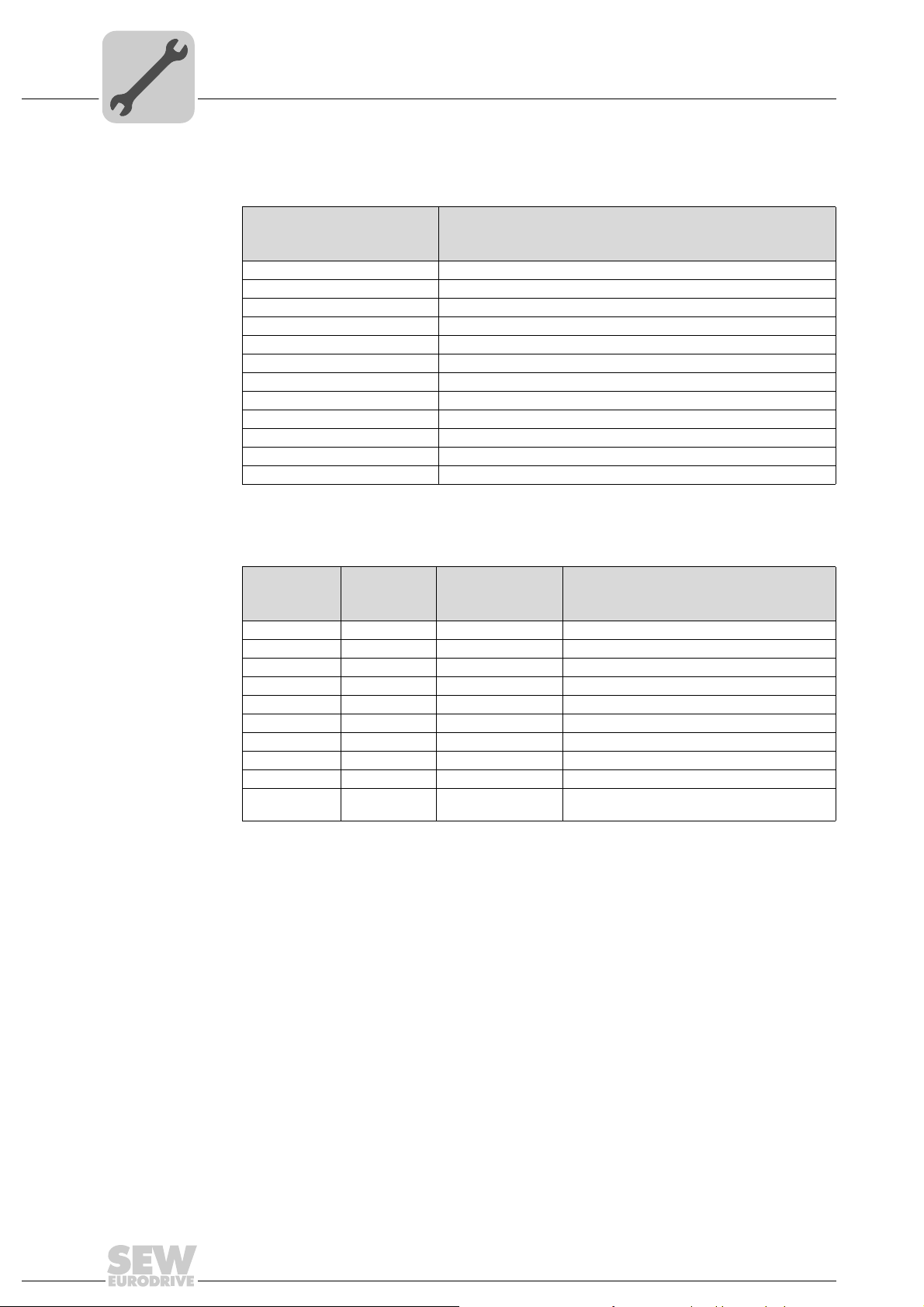
The following table shows the graduation and meaning of the signal words for safety
notes, warnings regarding potential risks of damage to property, and other notes.
Signal word Meaning Consequences if disregarded
DANGER! Imminent hazard Severe or fatal injuries
WARNING! Possible dangerous situation Severe or fatal injuries
CAUTION! Possible dangerous situation Minor injuries
NOTICE Possible damage to property Damage to the drive system or its envi-
NOTE Useful information or tip: Simpli-
fies handling of the drive system.
ronment
1.2.2 Design of the section-related safety notes
Section-related safety notes do not apply to a specific action, but to se veral actions per taining to one subject. The symbols used either indicate a general hazard or a specific
hazard.
This is the formal structure of a safety note for a specific section:
SIGNAL WORD!
Type and source of danger.
Possible consequence(s) if disregarded.
• Measure(s) to prevent the danger.
1.2.3 Design of the embedded safety notes
Embedded safety notes are directly integrated into the instructions just before the description of the dangerous action.
This is the formal structure of an embedded safety note:
• SIGNAL WORD! Type and source of hazard.
Possible consequence(s) if disregarded.
– Measure(s) to prevent the hazard.
Assembly and Operating Instructions – Gear Units R..7, F..7, K..7, K..9, S..7, SPIROPLAN® W
5
Page 6

1
General Information
Rights to claim under warranty
1.3 Rights to claim under warranty
A requirement of fault-free operation and fulfillment of any rights to claim under limited
warranty is that you adhere to the information in the documentation. Therefore read the
documentation before you start working with the unit.
1.4 Content of the documentation
This document contains additional safety-related information and conditions for operation in safety-related applications.
1.5 Exclusion of liability
You must comply with the information contained in this documentation to ensure safe
operation and to achieve the specified product characteristics and performance features. SEW-EURODRIVE assumes no liability for injury to persons or damage to equipment or property resulting from non-observance of the se operating instructions. In such
cases, any liability for defects is excluded.
1.6 Product names and trademarks
All product names in this documentation are trademarks or registered trademarks of
their respective titleholders.
1.7 Copyright
© 2013 – SEW-EURODRIVE. All rights reserved.
Unauthorized reproduction, modification, distribution or any other use of the whole or
any part of this documentation is strictly prohibited.
6
Assembly and Operating Instructions – Gear Units R..7, F..7, K..7, K..9, S..7, SPIROPLAN® W
Page 7
2 Safety Notes
The following basic safety notes must be read carefully to prevent injury to persons a nd
damage to property. The operator must ensure that the basic safety notes a re read and
adhered to. Make sure that persons responsible for the system and its operation, as
well as persons who work independently on the unit, have read through the operating
instructions carefully and understood them. If you are unclear about any of the inform ation in this documentation or if you require further information, please contact SEWEURODRIVE.
2.1 Preliminary information
Safety Notes
Preliminary information
2
The following safety notes are primarily concerned with the use of th e followin g components: Gear unit series R..7, F..7, K..7, K..9, S..7, SPIRO PLAN
gearmotors, you must also observe the safety notes for motors in the correspondin g operating instructions.
Also observe the supplementary safety notes in the individual sections of this documentation.
2.2 General information
WARNING
Danger of fatal injury or risk of injury during the operation of motors or gearmotors
caused by live, bare (in the event of open connectors/terminal boxes) and movable or
rotating parts.
Risk of burns caused by hot surfaces
Severe or fatal injuries
• All work related to transport, storage, installation, assembly, connection, startup,
maintenance and repair may only be carried out by qualified personnel.
• For transport, storage, installation, assembly, connection, startup, maintenance
and repair it is important that you adhere to the information in the following documents:
– Warning and safety signs on the motor/gearmotor
– All the project planning documents, startup instructions and wiring diagrams re-
lated to the drive
– System-specific regulations and requirements
– National/regional regulations governing the safety and prevention of accidents
• Never install damaged products.
• Never operate or energize the unit without the necessary protection covers or
housing.
• Use the unit only for its intended purpose.
• Make sure the unit is installed and operated properly.
®
W. If you are using
INFORMATION
In the event of damage caused by transport, submit a complaint to the shipping company immediately.
This documentation provides additional information.
Assembly and Operating Instructions – Gear Units R..7, F..7, K..7, K..9, S..7, SPIROPLAN® W
7
Page 8

2
2.3 Target group
Safety Notes
Target group
Any mechanical work may only be performed by adequately qualified person nel. Qualified personnel in the context of this documentation are persons familiar with the design,
mechanical installation, troubleshooting and servicing of the product who possess the
following qualifications:
• Training in mechanical engineering, e.g. as a mechanic or mechatronics technician
(final examinations must have been passed).
• They are familiar with these operating instructions.
Any electronic work may only be per form ed by adequately qualified electricians. Qualified electricians in the context of this documentation are persons familiar with electrical
installation, startup, troubleshooting and servicing of the product who possess the
following qualifications:
• Training in electrical engineering, e.g. as an electrician, electronics or mechatronics
technician (final examinations must have been passed).
• They are familiar with these operating instructions.
All work in further areas of transportation, stor age, operation and was te disposal must
only be carried out by persons who are trained appropriately.
All qualified personnel must wear appropriate protective clothing.
2.4 Designated use
The gear unit series R..7, F..7, K..7, K..9, S..7, SPIROPLAN® W is intended for use in
industrial systems.
The gear units may only be used according to the specifications in the technical documentation from SEW-EURODRIVE as well as the specifications on the nameplate. They
fulfill the applicable standards and regulations.
When installed in machines, startup (i.e. start of designated operation) is prohibited until
it is determined that the machine complies with the local laws and directives. In the individual area of application, you must especially observe the Machinery Directive
2006/42/EC as well as the EMC Directive 2004/108/EC. The EMC test specifications
EN 61000-4-2, EN 61000-4-3, EN 61000-4-4, EN 61000-4-6 and EN 61000-6-2 form
the basis for this.
Use in potentially explosive atmospheres is prohibited unless specifically designated
otherwise.
2.5 Other applicable documentation
The following publications and documents have to be observed as well:
• "DR.71 – 225, 315 AC Motors" operating instructions for gearmotor s
• Operating instructions of any attached options
• "Gear Units" catalog or
• "Gearmotors" catalog
8
Assembly and Operating Instructions – Gear Units R..7, F..7, K..7, K..9, S..7, SPIROPLAN® W
Page 9
2.6 Transport/storage
Inspect the shipment for any damage that may have occurred in transit as soon as you
receive the delivery. Inform the shipping com pany immediately in the event of damage.
It may be necessary to preclude startup.
Tighten the eyebolts securely. They are designed to carry only the weight of the
motor/gearmotor; do not attach any additional loads.
The built-in lifting eyebolts comply with DIN 580. Always observe the loads and regulations listed in this standard. If the gearmotor is equipped with two eyebolts, then both
should be used for transportation. In this case, the tension force vector of the slings must
not exceed a 45° angle according to DIN 580.
Use suitable, sufficiently rated handling equipment if required. Reattach these in the
case of further transportation.
Store the motor/gearmotor in a dry, dust-free environment if it is not to be installed
straight away. You must not store the motor/gearmotor outdoors or on the fan guard.
The motor/gearmotor can be stored for up to 9 months without requiring any special
measures before startup.
Safety Notes
Transport/storage
2
2.7 Setup
NOTICE
Danger due to static overdetermination if gear units with foot (e.g. KA19/29B,
KA127/157B or FA127/157B) are mounted both via the torque arm and via the foot
plate.
Risk of injuries and damage to property.
• Especially with the KA.9B/T variant, it is not permitted to use the foot plates and the
torque arm at the same time.
• The KA.9B/T variant may only be mounted via torque arms.
• K.9 or KA.9B variants may only be mounted via the foot plate.
• If you want to use foot plates and torque arms for mounting, consult with SEW- EURODRIVE.
Observe the notes in the "Mechanical Installation" section.
2.8 Startup/operation
Check the oil level before startup as described in chapter Inspection/Maintenance
(page 85).
Check that the direction of rotation is correct in decoupled status. Listen out for unusual
grinding noises as the shaft rotates.
Secure keys for test mode without output elements. Do not deactivate monitoring and
protection equipment even in test mode.
Switch off the gearmotor if in doubt whenever changes occur in rela tion to normal o peration (e.g. increased temperature, noise, vibration). Determine the cause and contact
SEW-EURODRIVE, if required.
2.9 Inspection/maintenance
Observe the notes in chapter "Inspection/Maintenance".
Assembly and Operating Instructions – Gear Units R..7, F..7, K..7, K..9, S..7, SPIROPLAN® W
9
Page 10
3
Gear Unit Structure
Basic structure of helical gear units
3 Gear Unit Structure
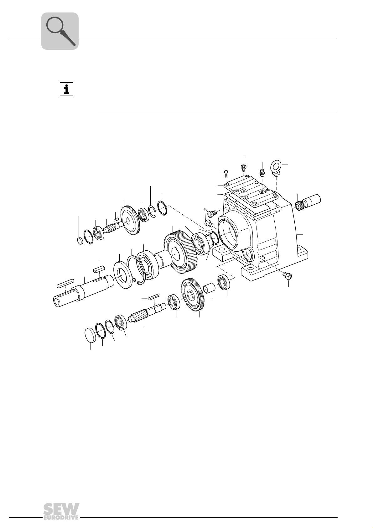
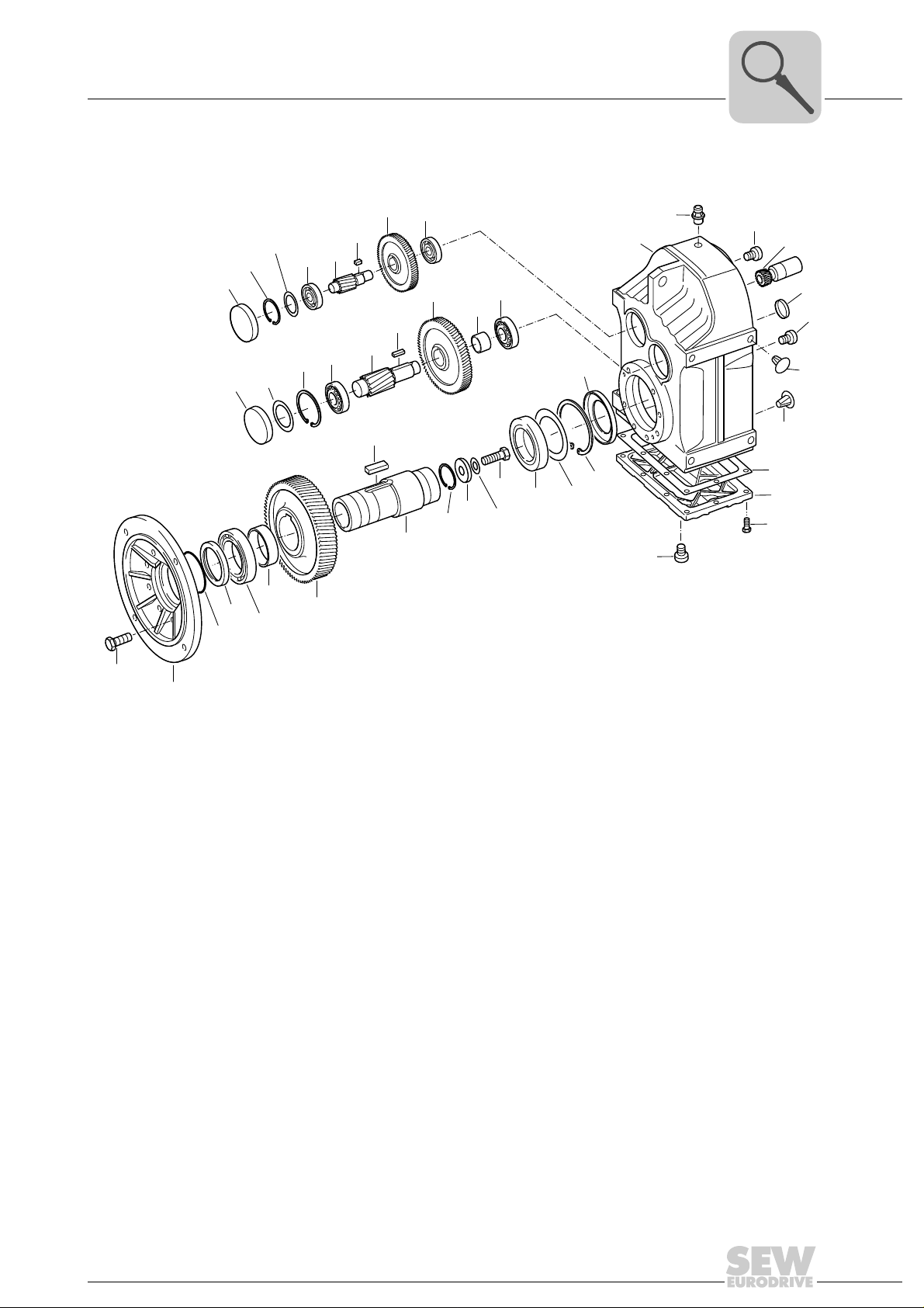
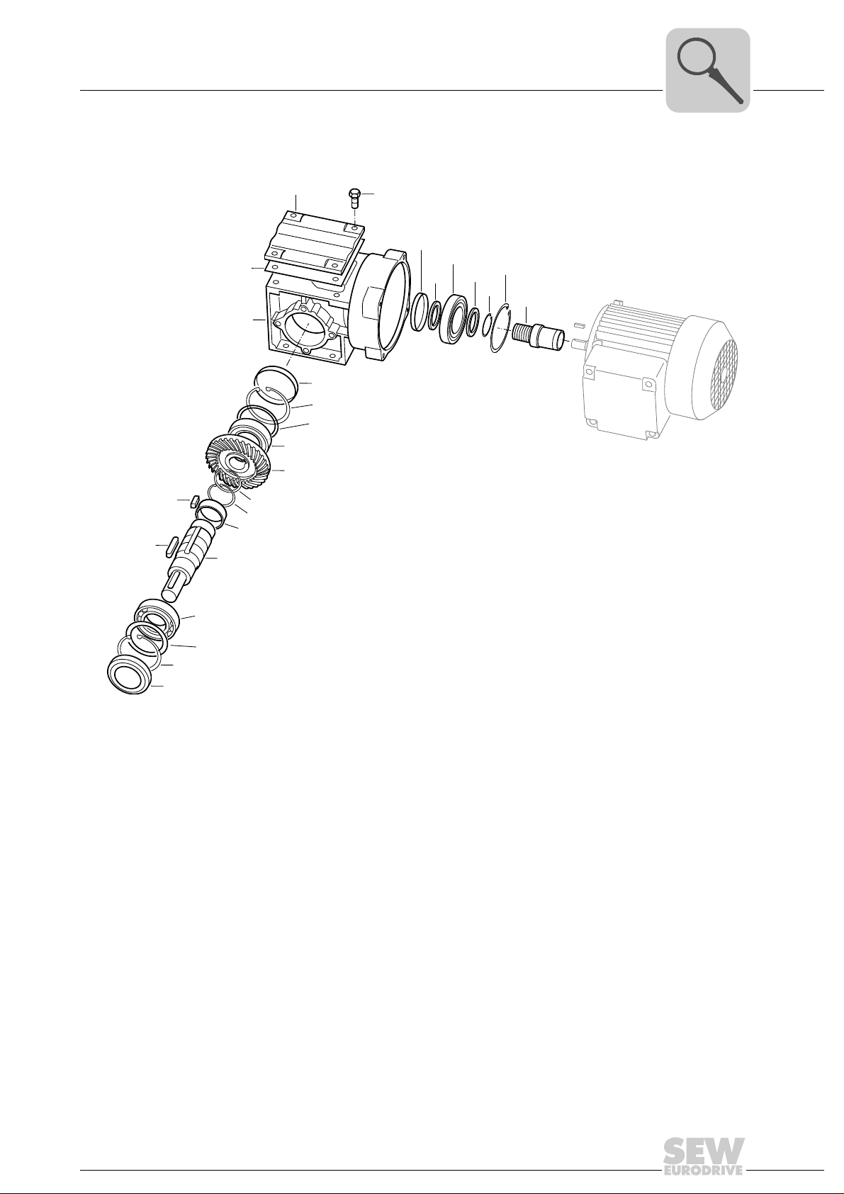
INFORMATION
The following figures are block diagrams. Their purpose is only to make it easier to assign components to the spare parts lists. Discrepancies may occur depending on the
gear unit size and version.
3.1 Basic structure of helical gear units
[8]
Pinion
[1]
Gear
[2]
Pinion shaft
[3]
Gear
[4]
Pinion shaft
[5]
Gear
[6]
Output shaft
[7]
Key
[8]
Oil seal
[9]
Rolling bearing bearing
[11]
Retaining ring
[12]
Spacer tube
[17]
[181]
[41]
[7]
[131]
[42]
[19]
[39]
[2]
[43]
[3]
[9]
[37]
[506]
[507]
[508]
Key
[19]
Breather valve
[20]
Gear unit housing
[22]
Eyebolt
[24]
Rolling bearing
[25]
Rolling bearing
[30]
Key
[31]
Spacer tube
[32]
Rolling bearing
[34]
Rolling bearing
[37]
Retaining ring
[39]
Retaining ring
[41]
[12]
[31]
[45]
[11]
[5]
[515]
[516]
[517]
[47]
[17]
[6]
[34]
[25]
[88]
[42]
[43]
[45]
[47]
[59]
[88]
[100]
[101]
[102]
[131]
[181]
[506]
[101]
[100]
[102]
[59]
[521]
[522]
[523]
[30]
[32]
[4]
Rolling bearing
Key
Rolling bearing
Retaining ring
Screw plug
Retaining ring
Inspection cover
Hex head screw
Gasket
Closing cap
Closing cap
Shim
[59]
[20]
[507]
[508]
[515]
[516]
[517]
[521]
[522]
[523]
[24]
[1]
[22]
[59]
19194251
Shim
Shim
Shim
Shim
Shim
Shim
Shim
Shim
10
Assembly and Operating Instructions – Gear Units R..7, F..7, K..7, K..9, S..7, SPIROPLAN® W
Page 11
Gear Unit Structure
[181]
[41]
[517]
[508]
[516]
[507]
[515]
[506]
[42]
[3]
[43]
[2]
[45]
[30]
[59]
[101]
[100]
[102]
[160]
[165]
[161]
[59]
[59]
[20]
[22]
[1]
[521]
[522]
[523]
[25]
[88]
[183]
[32]
[4]
[31]
[5]
[37]
[39]
[131]
[14]
[16]
[81]
[9]
[11]
[17]
[6]
[7]
[91]
[92]
[93]
[94]
[19]
Basic structure of parallel-shaft helical gear units
3.2 Basic structure of parallel-shaft helical gear units
3
Pinion
[1]
Gear
[2]
Pinion shaft
[3]
Gear
[4]
Pinion shaft
[5]
Gear
[6]
[7]
[9]
[11]
[14]
[16]
[17]
[19]
[20]
Hollow shaft
Oil seal
Rolling bearing bearing
Hex head screw
Output flange
Spacer tube
Key
Breather valve
Gear unit housing
[22]
Rolling bearing
[25]
Rolling bearing
[30]
Key
[31]
Spacer tube
[32]
Rolling bearing
[37]
Retaining ring
[39]
Retaining ring
[41]
Rolling bearing
[42]
Key
[43]
Rolling bearing
[45]
Screw plug
[59]
Shield ring
[81]
Retaining ring
[88]
Retaining ring
[91]
Washer
[92]
Lock washer
[93]
Hex head screw
[94]
Inspection cover
[100]
Hex head screw
[101]
Gasket
[102]
Closing cap
[131]
Closing plug
[160]
Closing cap
[161]
Closing plug
[165]
Closing cap
[181]
Oil seal
[183]
[506]
[507]
[508]
[515]
[516]
[517]
[521]
[522]
[523]
19298059
Shim
Shim
Shim
Shim
Shim
Shim
Shim
Shim
Shim
Assembly and Operating Instructions – Gear Units R..7, F..7, K..7, K..9, S..7, SPIROPLAN® W
11
Page 12
3
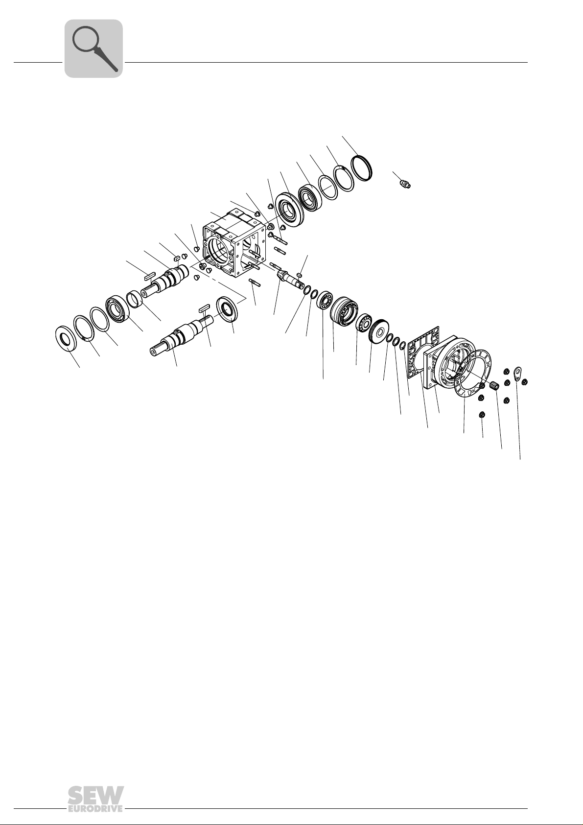
[9]
[12]
[518]
[519]
[520]
[11]
[17]
[36]
[24]
[1]
[29]
[26]
[44]
[115]
[163]
[530]
[531]
[532]
[2]
[45]
[141]
[42]
[536]
[537]
[538]
[43]
[5]
[150]
[7]
[80]
[183]
[48]
[8]
[7]
[19]
[59]
[159]
[88]
[521]
[522]
[523]
[25]
[6]
[167]
[59]
[22]
[106]
[20]
[89]
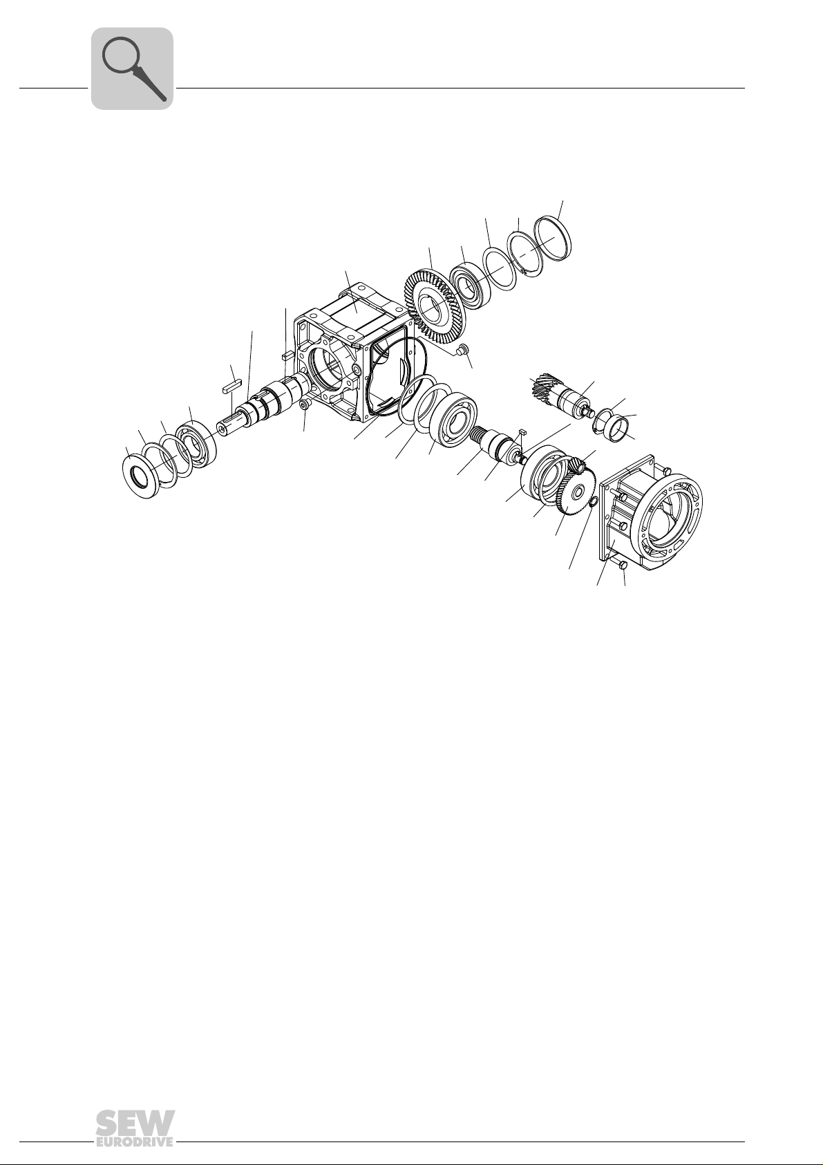
Gear Unit Structure
Basic structure of helical-bevel gear units K..9
3.3 Basic structure of helical-bevel gear units K..9
Pinion
[1]
Gear
[2]
Pinion shaft
[5]
Gear
[6]
Output shaft
[7]
Key
[8]
Oil seal
[9]
Deep groove ball bearing
[11]
Retaining ring
[12]
Spacer tube
[17]
Key
[19]
Breather valve
[20]
Gear unit housing
[22]
Eyebolt
[24]
Deep groove ball bearing
[25]
[26]
[29]
[36]
[42]
[43]
[44]
[45]
[48]
[59]
[62]
[63]
Housing stage 1
Gasket
Stud
Tapered roller bearing
Key
Gasket
Tapered roller bearing
Supporting ring (only K..29)
Screw plug
Screw plug
Thread reduction
Key
[80]
Retaining ring
[88]
Closing cap
[89]
Stud
[106]
Retaining ring
[115]
Bushing
[141]
Hex nut
[150]
Closing plug
[159]
Supporting ring
[163]
Closing plug
[167]
Oil seal
[183]
Shim
[518]
Shim
[519]
[520]
[521]
[522]
[523]
[530]
[531]
[532]
[536]
[537]
[538]
7421610507
Shim
Shim
Shim
Shim
Shim
Shim
Shim
Shim
Shim
Shim
12
Assembly and Operating Instructions – Gear Units R..7, F..7, K..7, K..9, S..7, SPIROPLAN® W
Page 13
Gear Unit Structure
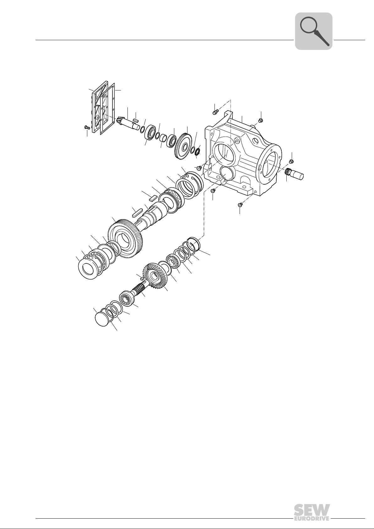
[100]
[102]
[3]
[101]
[43]
[538]
[535]
[537]
[534]
[536]
[533]
[42]
[119]
[45]
[2]
[20]
[22]
[59]
[59]
[59]
[59]
[1]
[114]
[113]
[116]
[89]
[59]
[88]
[521]
[522]
[523]
[25]
[84]
[19]
[8]
[7]
[6]
[17]
[83]
[11]
[12]
[9]
[37]
[5]
[4]
[30]
[135]
[542]
[543]
[544]
[133]
[132]
[161]
[31]
[506]
[507]
[508]
[137]
[39]
[131]
Basic structure of helical-bevel gear units K..37 – K..187
3.4 Basic structure of helical-bevel gear units K..37 – K..187
3
[25]
[30]
[31]
[37]
[39]
[42]
[43]
[45]
[59]
[83]
[84]
[88]
[89]
[100]
[101]
Pinion
[1]
Gear
[2]
Pinion shaft
[3]
[4]
[5]
[6]
[7]
[8]
[9]
[11]
[12]
[17]
[19]
[20]
[22]
Assembly and Operating Instructions – Gear Units R..7, F..7, K..7, K..9, S..7, SPIROPLAN® W
Gear
Pinion shaft
Gear
Output shaft
Key
Oil seal
Rolling bearing bearing
Retaining ring
Spacer tube
Key
Breather valve
Gear unit housing
Rolling bearing
Rolling bearing
Key
Rolling bearing
Retaining ring
Rolling bearing
Key
Rolling bearing
Screw plug
Shield ring
Shield ring
Retaining ring
Closing cap
Inspection cover
Hex head screw
Gasket
[102]
Slotted nut
[113]
Lock washer
[114]
Threadlocker
[116]
Spacer tube
[119]
Closing cap
[131]
Retaining ring
[132]
Supporting ring
[133]
Shield ring
[135]
Closing cap
[161]
Shim
[506]
Shim
[507]
Shim
[508]
Shim
[521]
Shim
[521]
[522]
[523]
[533]
[534]
[535]
[536]
[537]
[538]
[542]
[543]
[544]
19301131
Shim
Shim
Shim
Shim
Shim
Shim
Shim
Shim
Shim
Shim
Shim
13
Page 14
3
[131]
[39]
[137]
[507]
[506]
[37]
[5]
[43]
[30]
[9]
[12]
[520]
[519]
[518]
[11]
[6]
[7]
[25]
[88]
[89]
[59]
[523]
[522]
[521]
[19]
[2]
[59]
[102]
[101]
[59]
[20]
[22]
[1]
[100]
[61]
Gear Unit Structure
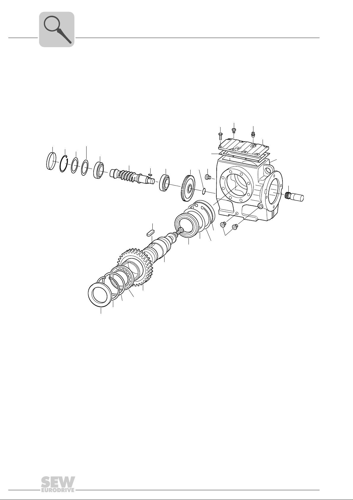
Basic structure of helical-worm gear units
3.5 Basic structure of helical-worm gear units
Pinion
[1]
Gear
[2]
Worm gear
[5]
Worm gear
[6]
Output shaft
[7]
Oil seal
[9]
Rolling bearing bearing
[11]
Retaining ring
[12]
Key
[19]
Breather valve
[20]
Gear unit housing
[22]
Rolling bearing
[25]
Rolling bearing
[30]
Rolling bearing
[37]
Retaining ring
[39]
Key
[43]
Screw plug
[59]
Retaining ring
[61]
Retaining ring
[88]
Closing cap
[89]
Inspection cover
[100]
Hex head screw
[101]
Gasket
[102]
Closing cap
[131]
Supporting ring
[137]
Shim
[506]
Shim
[507]
[518]
[519]
[520]
[521]
[522]
[523]
19304203
Shim
Shim
Shim
Shim
Shim
Shim
14
Assembly and Operating Instructions – Gear Units R..7, F..7, K..7, K..9, S..7, SPIROPLAN® W
Page 15
Gear Unit Structure
[1]
[68]
[72]
[143]
[66]
[71]
[65]
[100]
[102]
[22]
[89]
[521]
[522]
[523]
[88]
[25]
[6]
[250]
[251]
[17]
[7]
[11]
[8]
[19]
[518]
[519]
[520]
[12]
[9]
[101]
Basic structure of SPIROPLAN® gear units W..10 – W..30
3.6 Basic structure of SPIROPLAN® gear units W..10 – W..30
3
Pinion
[1]
Gear
[6]
Output shaft
[7]
Key
[8]
Oil seal
[9]
Rolling bearing bearing
[11]
[12]
[17]
Retaining ring
Spacer tube
Key
[19]
[22]
[25]
[65]
[66]
[68]
[71]
[72]
Gear unit housing
Rolling bearing
Oil seal
Rolling bearing bearing
Retaining ring
Supporting ring
Retaining ring
[88]
[89]
[100]
[101]
[102]
[143]
[250]
[251]
Retaining ring
Closing cap
Inspection cover
Hex head screw
Gasket
Supporting ring
Retaining ring
Retaining ring
[518]
[519]
[520]
[521]
[522]
[523]
19307275
Shim
Shim
Shim
Shim
Shim
Shim
Assembly and Operating Instructions – Gear Units R..7, F..7, K..7, K..9, S..7, SPIROPLAN® W
15
Page 16
3
Gear Unit Structure
Basic structure of SPIROPLAN® gear units W..37 – W..47
3.7 Basic structure of SPIROPLAN® gear units W..37 – W..47
[518]
[519]
[520]
[12]
[9]
Pinion
[1]
Gear
[2]
Pinion shaft
[5]
Gear
[6]
Output shaft
[7]
Key
[8]
Oil seal
[9]
Deep groove ball bearing
[11]
Retaining ring
[12]
Key
[19]
[11]
[8]
[19]
[7]
[59]
Gear unit housing
[22]
Deep groove ball bearing
[25]
Housing stage 1
[26]
Deep groove ball bearing
[30]
Key
[31]
Spacer tube
[32]
Retaining ring
[33]
Hex head screw
[36]
Deep groove ball bearing
[37]
O-ring
[44]
[22]
[44]
[133]
[506]
[6]
[37]
[59]
[61]
[88]
[89]
[133]
[137]
[506]
[518]
[519]
[520]
[521]
[522]
[523]
[25]
[59]
[5]
[31]
[30]
Screw plug
Retaining ring
Retaining ring
Closing cap
Shim
Shim
Shim
Shim
Shim
Shim
[88]
[137]
[2]
[89]
[61]
[26]
[5]
[1]
[521]
[522]
[523]
[33]
[32]
[36]
9007199860613387
Shim
Shim
Shim
16
Assembly and Operating Instructions – Gear Units R..7, F..7, K..7, K..9, S..7, SPIROPLAN® W
Page 17
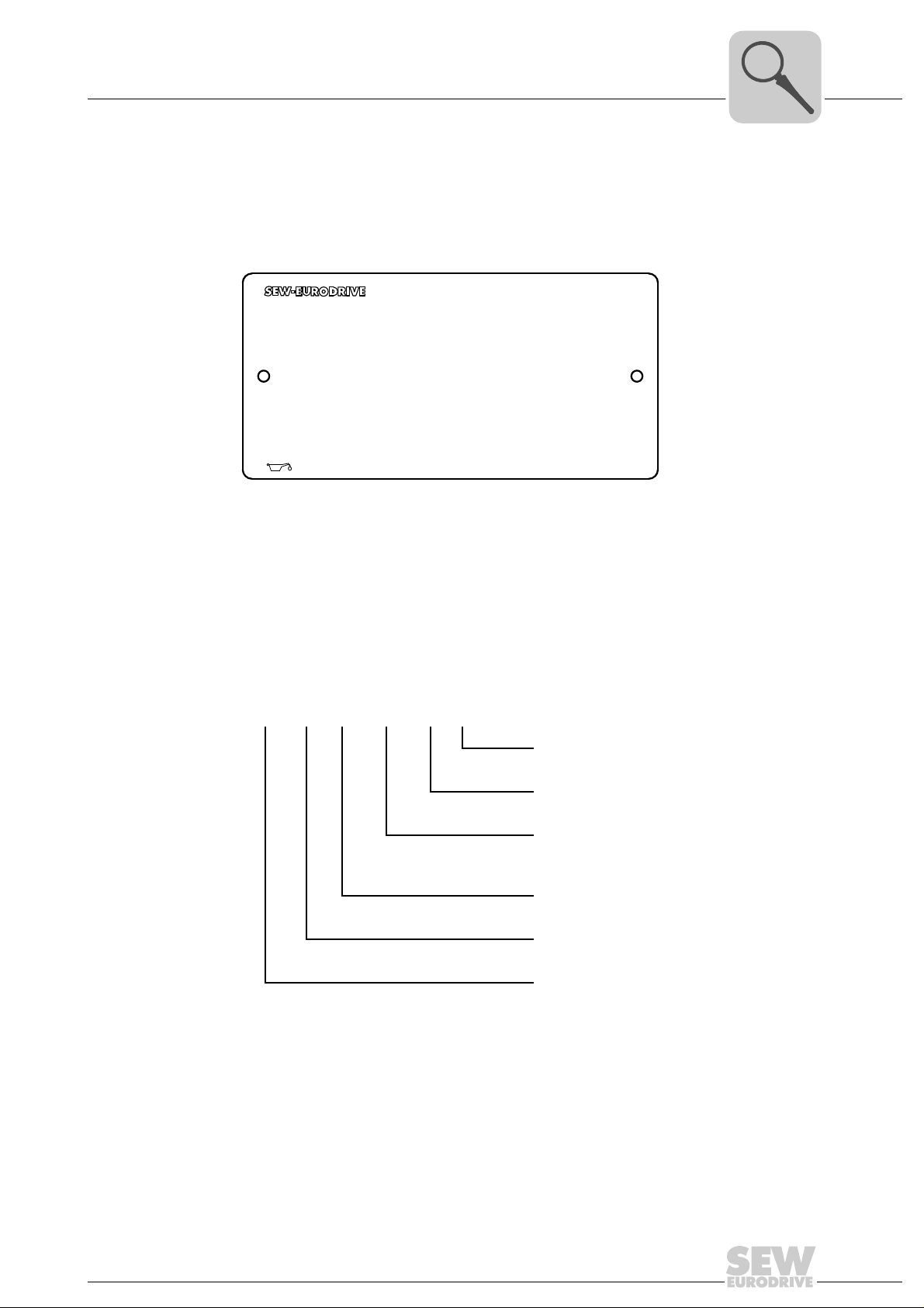
3.8 Nameplate/type designation
76646 Bruchsal
na
Mamax
Nm
Memax
Nm
IM
i
kg
M1A
70,46
105
2700
r/min
1400/20
K87 AD4
Made in Germany
06415911
CLP HC 220 Synth. Öl / 3,71l
41
3.8.1 Nameplate
The following figure shows an example of a nameplate for a helical-bevel gear unit with
input cover:
Gear Unit Structure
Nameplate/type designation
4472018699
3
n
a
M
amax
M
emax
i Gear unit ratio
IM Mounting position
3.8.2 Type designation
Helical-bevel gear
units
A helical-bevel gear unit with AQ adapter has, for example, the following type designation:
[r/min] Maximum permitted output speed
[Nm] Maximum permitted output torque
[Nm] Maximum permitted input torque
K37/RAQA80/1
Variants
Flange classification
Adapter designation: e.g. for servomotors
- AQA: Adapter with keyway
- AQH: Adapter with clamping ring hub
Option: e.g. for servo gear units .../ R:
Reduced circumferential backlash
Gear unit size: e.g. B. 37
Assembly and Operating Instructions – Gear Units R..7, F..7, K..7, K..9, S..7, SPIROPLAN® W
Gear unit type: e.g. K
17
Page 18
4
Mechanical Installation
Required tools/resources
4 Mechanical Installation
4.1 Required tools/resources
• Set of wrenches
• If necessary, torque wrench for:
– Shrink disks
– Motor adapter AQH Or EWH
– Input shaft assembly with centering shoulder
• Mounting device
• Compensation elements (shims, spacing rings)
• Fasteners for input and output elements
• Lubricant (e.g. NOCO
®
Fluid)
• Bolt locking compound (for input shaft assembly with centering shoulder), e.g.
Loctite
Standard parts are not included in the delivery
4.1.1 Installation tolerances
Shaft end Flanges
Diameter tolerance in accordance with DIN 748
• ISO k6 for solid shafts with Ø ≤ 50 mm
• ISO m6 for solid shafts with Ø > 50 mm
• ISO H7 for hollow shafts
• Center bore in accordance with DIN 332, shape
DR
®
243
Centering shoulder tolerance to DIN 42948
• ISO j6 for b1 ≤ 230 mm
• ISO h6 with b1 > 230 mm
18
Assembly and Operating Instructions – Gear Units R..7, F..7, K..7, K..9, S..7, SPIROPLAN® W
Page 19
4.2 Installation requirements
CAUTION
Risk of injury due to protruding gear unit parts.
Minor injuries.
• Keep a sufficient safety distance to the gear unit/gearmotor.
NOTICE
Damage to the gear unit/gearmotor due to improper installation.
Possible damage to property
• Strictly adhere to the notes in this chapter.
Make sure that the following requirements are met before you start installing the unit:
• The drive has not been damaged during transportation or storage.
Mechanical Installation
Installation requirements
4
• The entries on the nameplate of the gearmotor match the voltage supply system.
• When the unit is installed in abrasive ambient conditions, protect the output end oil
seals against wear.
• The output shafts and flange surfaces must be completely free from anti-corrosion
agents, contamination or similar. Use a commercially available solvent for cleaning.
Do not expose the sealing lips of the oil se als to the solvent – damage to the material.
• For standard drives:
– Ambient temperature according to the technical documentation, nameplate and
lubricant table in section "Lubricants".
– No harmful oils, acids, gases, vapors, radiation etc. in the vicinity
• For special designs:
– The drive is designed in accordance with the ambien t conditions. Observe the in-
formation on the nameplate.
®
• For helical-worm/SPIROPLAN
– No large external mass moments of inertia which could ex ert a retrodriving load
on the gear unit.
– Self-locking with η’ (retrodriving) < 0.5;
Calculation : η’ = 2 – 1/η
• For servomotor mounting:
– Do not assemble the drive without having ensured that there will be sufficient ven-
tilation after installation to prevent heat build-up.
W gear units:
Assembly and Operating Instructions – Gear Units R..7, F..7, K..7, K..9, S..7, SPIROPLAN® W
19
Page 20
4
Mechanical Installation
Installing the gear unit
4.3 Installing the gear unit
NOTICE
Danger due to static overdetermination if gear units with foot (e.g. KA19/29B,
KA127/157B or FA127/157B) are mounted both via the torque arm and via the foot
plate.
Risk of injuries and damage to property.
• Especially with the KA.9B/T variant, it is not permitted to use the foot plates and the
torque arm at the same time.
• The KA.9B/T variant may only be mounted via torque arms.
• K.9 or KA.9B variants may only be mounted via the foot plate.
• If you want to use foot plates and torque arms for mounting, consult with SEWEURODRIVE.
CAUTION
Improper installation may result in damage to the gear unit or gearmotor.
Possible damage to property.
• Protect the gear unit from direct cold air currents. Condensation may cause water
to accumulate in the oil.
• It is important that you observe the notes in this chapter.
CAUTION
Risk of trapping and crushing due to improper disassembly of heavy components.
Risk of injury.
• Remove the shrink disk properly.
• Work on the gear unit only when the machine is at a standstill. Secure the drive unit
against unintentional power-up.
The gear unit or gearmotor is only allowed to be installed in the specified mounting
position. Observe the information on the nameplate. SPIROPLAN
W10 – W30 are mounting position-independent.
The support structure must have the followin g fe at ur es :
• Level
• Vibration damping
• Torsionally rigid
The following table shows the ma ximally permit ted flatne ss defect for foot- an d flange-
mounting (guide values based on DIN ISO 1101) :
• Gear unit size ≤ 67: Max. 0.4 mm
• Gear unit size 77 – 107: Max. 0.5 mm
• Gear unit size 137 – 147: Max. 0.7 mm
• Gear unit size 157 – 187: Max. 0.8 mm
®
gear units of size
20
Do not tighten the housing legs and mounting flanges against one another and ensure
that you comply with the permitted overhung and axial loads. Observe chapter "Project
Planning" in the Gear unit/gearmotor catalog for calculating the permitted over hung and
axial loads.
Assembly and Operating Instructions – Gear Units R..7, F..7, K..7, K..9, S..7, SPIROPLAN® W
Page 21

Mechanical Installation
Installing the gear unit
Secure gearmotors using quality 8.8 screws.
Secure the following gearmotors using quality 10.9 screws:
• RF37, R37F with flange Ø = 120 mm
• RF37, RF47, R47F with flange Ø = 140 mm
• RF57, R57F with flange Ø = 160 mm
• FF, FAF, KF, KAF with flange Ø 250 mm
• and RZ37, RZ47, RZ57, RZ67, RZ77, RZ87
INFORMATION
When installing the gear unit, make sure that the oil level and drain plugs as well as
the breather plugs are easily accessible!
At the same time, also check that the oil fill corresponds to the specifications for the intended mounting position (see chapter "Lubricant fill quantities (page 139)" or refer to
the information on the nameplate). The gear units a re fi lled with the requ ired oil vol ume
at the factory. There may be slight deviations at the oil level plug as a result of the mounting position, which are permitted within the manufacturing tolerances.
Adjust the lubricant fill volumes and the positio n of the breather valve accordingly
in the event of a change of mounting position. Observe chapter "Lubricant fill quan-
tities" and chapter "Mounting Positions".
Consult the SEW customer service if you intend to change the mounting position of K
gear to M5 or M6 or between M5 and M6.
Please contact our SEW customer service if you want to change the mounting position
of size S47 – S97 helical-worm gear units to mounting position M2 or M3.
Use plastic inserts (2 – 3 mm thick) if there is a risk of electrochemical corrosion between
the gear unit and the driven machine. The material used must have an electrical leakage
resistance < 10
ample, cast iron and high-grade steel. Also fit the bolts with plastic wash ers. Ground the
housing additionally – use the grounding bolts on the motor.
9
Ω. Electrochemical corrosion can occur between various metals, for ex-
4
Assembly and Operating Instructions – Gear Units R..7, F..7, K..7, K..9, S..7, SPIROPLAN® W
21
Page 22
4
Mechanical Installation
Installing the gear unit
4.3.1 Tightening torques for retaining screws
Mount the gearmotors with the following tightening torques:
Bolt/nut
M6 11
M8 25
M10 48
M12 86
M16 210
M20 410
M24 710
M30 1450
M36 2500
M42 4600
M48 6950
M56 11100
Tightening torque screw / nut
Strength class 8.8
[Nm]
Mount the specified gearmotors in flange-mounted design with the following increased
tightening torques:
Flange Gear unit
120 RF37 M6 14
140 RF37, RF47 M8 35
160 RF57 M8 35
60ZR RZ37 M8 35
70ZR RZ47 M8 35
80ZR RZ57 M10 69
95ZR RZ67 M10 69
110ZR RZ77 M12 120
130ZR RZ87 M12 120
250
FF77, KF77,
FAF77, KAF77
Bolt/nut
M12 120
Tightening torque screw / nut
Strength class 10.9
[Nm]
22
Assembly and Operating Instructions – Gear Units R..7, F..7, K..7, K..9, S..7, SPIROPLAN® W
Page 23

4.3.2 Gear unit mounting
INFORMATION
For gear units in foot/flange-mounted design in connection with VARIBLOC® variablespeed gear units, use quality 10.9 bolts and suitable washers for connecting the customer flange.
To improve the friction contact between flange and mounting surface, SEWEURODRIVE recommends anaerobic gaskets or an anaerobic glue.
Mechanical Installation
Installing the gear unit
4
Foot-mounted gear
units
Gear units with
B14 flange design
and/or hollow shaft
The following table shows the thread sizes of the foot-mounted g ear units depending on
the gear unit type and size:
Gear unit type
Screw
M6 07 19 10/20
M8 17/27/37 27/37 29 37 30/37/47
M10 57 47 37/47 47/57
M12 47/57/67 67 57/67 57/67 67
M16 77/87 77/87 77/87 77 77
M20 97 97/107 97 87 87
M24 107 107 97 97
M30 137 127 107/167
M36 147/167 157 127/157/187
R / R..F RX F /
FH..B / FA..B
K / KH..B /
KV..B / KA..B
S W
The following table shows the thread sizes of the ge ar units with B1 4 flan ge a nd/o r hollow shaft depending on the gear unit type and size:
Gear unit type
Screw RZ FAZ / FHZ KAZ /
KHZ / KVZ
M6 07/17/27 37 10/20/30
M8 37/47 27/37/47 37/47 47/57 37
M10 57/67 47
M12 77/87 57/67/77 57/67/77 67/77
M16 87/97 87/97 87/97
M20 107/127 107/127
M24 157 157
1) For W30 gear units mounted directly to a CMP motor or mounted via an EWH.. adapter, the thread size
is M8.
SA /
SAZ / SHZ
WA
1)
Assembly and Operating Instructions – Gear Units R..7, F..7, K..7, K..9, S..7, SPIROPLAN® W
23
Page 24
4
Mechanical Installation
Installing the gear unit
Gear units with B5
flange
The following table shows the thread s izes of the gear units with B5 flange dependin g
on the gear unit type, size and flange diameter:
Gear unit type
Flange Ø
[mm]
80 M6 10
110 M8 20
120 M6 07/17/27 19 37 10/20/30/37
140 M8 07/17/27/37/47
160 M8 07/17/27/37/47 27/37 19/29/37 37/47 30/37/47
200 M10 37/47/57/67 47 29/47 57/67
250 M12 57/67/77/87 57/67 57/67 77
300 M12 67/77/87 77 77
350 M16 77/87/97/107 87 87 87
450 M16 97/107/137/147 97/107 97/107 97
550 M16 107/13 7/147/167 127 127
660 M20 147/167 157 157
Screw RF /
R..F / RM
FF /
FAF / FHF
KF / KAF /
KHF / KVF
SF /
SAF /SHF
WF / WAF
24
Assembly and Operating Instructions – Gear Units R..7, F..7, K..7, K..9, S..7, SPIROPLAN® W
Page 25

4.3.3 Installation in damp locations or outdoors
Drives are supplied in corrosion-resistant versions with a surface protection coating for
use in damp areas or outdoors. Repair any damage to the paint work (e.g. on the
breather valve or the eyebolts).
Mechanical Installation
Installing the gear unit
4
When mounting the motors onto AM, AQ adapters and to AR, AT start-up and friction
couplings, seal the flange areas with a suitable sealing compound, e.g. Loctite
Units installed outdoors must be protected from the sun. Suitable protective devices a re
required, such as covers or roofs. Avoid any heat accumulation. The operator must ensure that foreign objects do not impair the function of the gear unit (e.g. falling objects
or coverings).
4.3.4 Gear unit venting
The following gear units do not require venting:
• R..07 in mounting positions M1, M2, M3, M5 and M6
• R..17, R..27 and F..27 in mounting positions M1, M3, M5 and M6
• SPIROPLAN
• SPIROPLAN
• K..19, K..29 gear units in mounting positions M1, M2, M3, M5 and M6
SEW-EURODRIVE supplies all other gear units with the breath er valve installed and ac-
tivated according to the particular mounting position.
Exceptions:
1. SEW su pplies the following gear units with a screw plug on the vent hole provided:
M6
®
574.
®
W..10, W..20, W..30 gear units
®
W..37, W..47 gear units in mounting positions M1, M2, M3, M5 and
– Gear units with pivoted mounting positions, if possible
– Gear units for inclined mounting
The breather valve is located in the motor terminal box. Before startup, replace the
highest screw plug with the breather valve provided.
2. SEW supplies a breather valve in a plastic bag for mount-on gear units requiring
venting on the input side.
3. Enclosed gear units are supplied without a breather valve.
4. In some countries, the breather valve is installed, but not activated due to possible
pressure fluctuations during transport. In these cases, the breather valve must be activated by removing the transport protection as described in chapter "Activating the
breather valve".
Assembly and Operating Instructions – Gear Units R..7, F..7, K..7, K..9, S..7, SPIROPLAN® W
25
Page 26
4
Mechanical Installation
Installing the gear unit
Activating the
breather valve
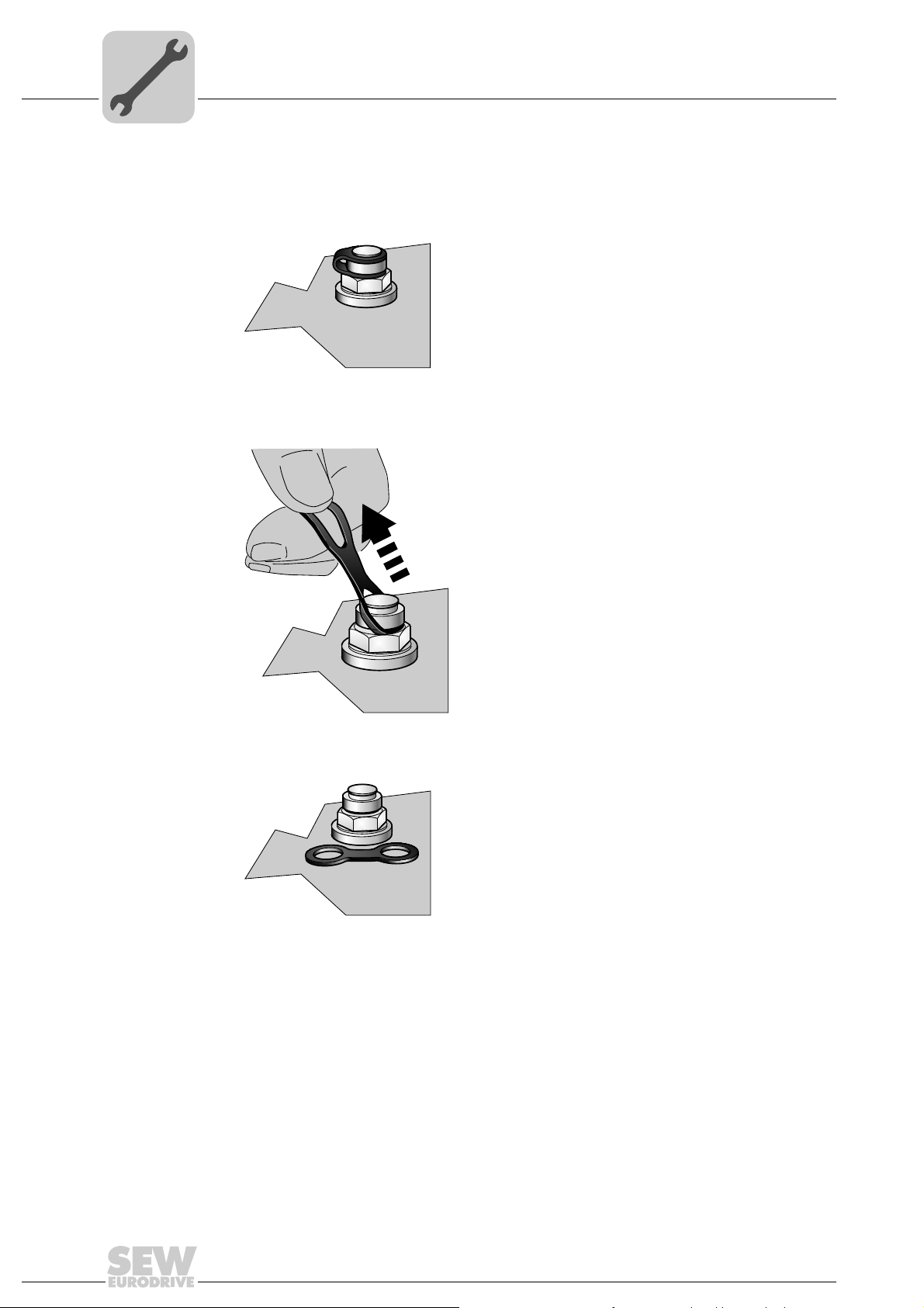
Check whether the breather valve is activate d. If the breather valv e has not been activated, you must remove the transportation protection device from the breather valve before starting up the gear unit.
1. Breather valve with transportation protection device
211319051
2. Remove transport fixture
211316875
3. Activated breather valve
211314699
26
Assembly and Operating Instructions – Gear Units R..7, F..7, K..7, K..9, S..7, SPIROPLAN® W
Page 27
4.3.5 Painting the gear unit
NOTICE
Breather valves and oil seals may be damaged during painting or re-painting.
Possible damage to property.
• Thoroughly cover the breather valves and the sealing lip of the oil seals with strips
prior to painting.
• Remove the strips after painting .
4.4 Gear units with solid shaft
4.4.1 Notes on installation
INFORMATION
Mounting is easier if you first apply lubricant to the output element or heat it up briefly
(to 80 - 100 °C).
Mechanical Installation
Gear units with solid shaft
4
4.4.2 Assembling input an d ou t pu t ele m en t s
NOTICE
Bearing, hosing or shaft may be damaged due to improper assembly.
Possible damage to property
• Assemble the input and output components only using a mounting device. Use the
center bore and the thread on the shaft end for positioning.
• Never force belt pulleys, couplings, pinions, etc. onto the shaft end by hitting them
with a hammer.
• In the case of belt pulleys, make sure the belt is tensioned correctly in accordance
with the manufacturer's instructions.
• Power transmission elements should be balanced after fitting and must not give
rise to any impermissible radial or axial forces (see the "Gearmotors" or "ExplosionProof Drives" catalog for permitted values).
Using a mounting
device
The following figure shows a mounting device for installing couplings or hubs on gear
unit or motor shaft ends. Should you be able to tighten the screw without any problems,
you may not need the thrust bearing on the mounting device.
[1]
[2]
[3]
211368587
[1] Gear unit shaft end
[2] Thrust bearing
[3] Coupling hub
Assembly and Operating Instructions – Gear Units R..7, F..7, K..7, K..9, S..7, SPIROPLAN® W
27
Page 28
4
[A] [B]
[1]
[1]
a)
b) c)
Mechanical Installation
Gear units with solid shaft
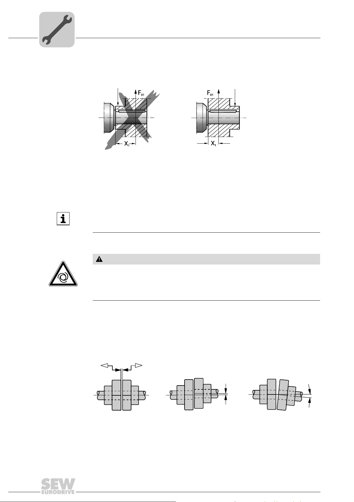
Avoiding excessive
overhung loads
Avoid high overhung loads by installing the gear or chain sprocket according to figure B
if possible.
211364235
[1] Hub
[A] Unfavorable
[B] Correct
INFORMATION
Mounting is easier if you first apply lubricant to the output element or heat it up briefly
(to 80 - 100 °C).
4.4.3 Mounting of couplings
CAUTION
Risk of injury due to moving drive elements, such as belt pulleys or couplings, during
operation.
Risk of jamming and crushing.
• Cover input and output components with a touch guard.
Adjust the following misalignments according to the coupling manufacturer's specifications when mounting couplings:
a) Maximum and minimum clearance
b) Axial offset
c) Angular offset
211395595
28
Assembly and Operating Instructions – Gear Units R..7, F..7, K..7, K..9, S..7, SPIROPLAN® W
Page 29
Torque arms for shaft-mounted gear units
c
a
øb
+0.5
ød
[1]
[2]
[3]
4.5 Torque arms for shaft-mounted gear units
NOTICE
Improper mounting may result in damage to the gear unit.
Possible damage to property.
• Do not place torque arms under strain when mounting.
• Use screws of quality 8.8 to fasten torque arms.
4.5.1 Parallel-shaf t he li ca l ge ar units
The following figure shows the torque arm for parallel-shaft helical gear units.
Mechanical Installation
4
9007199466107403
[1] Screw
[2] Washer
[3] Nut
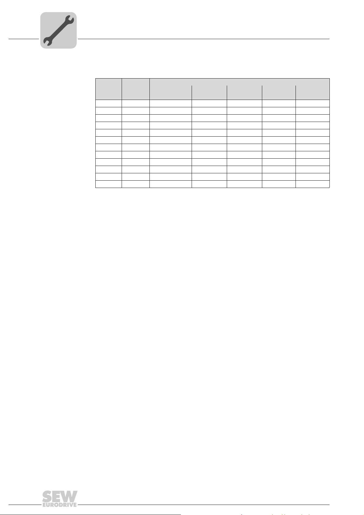
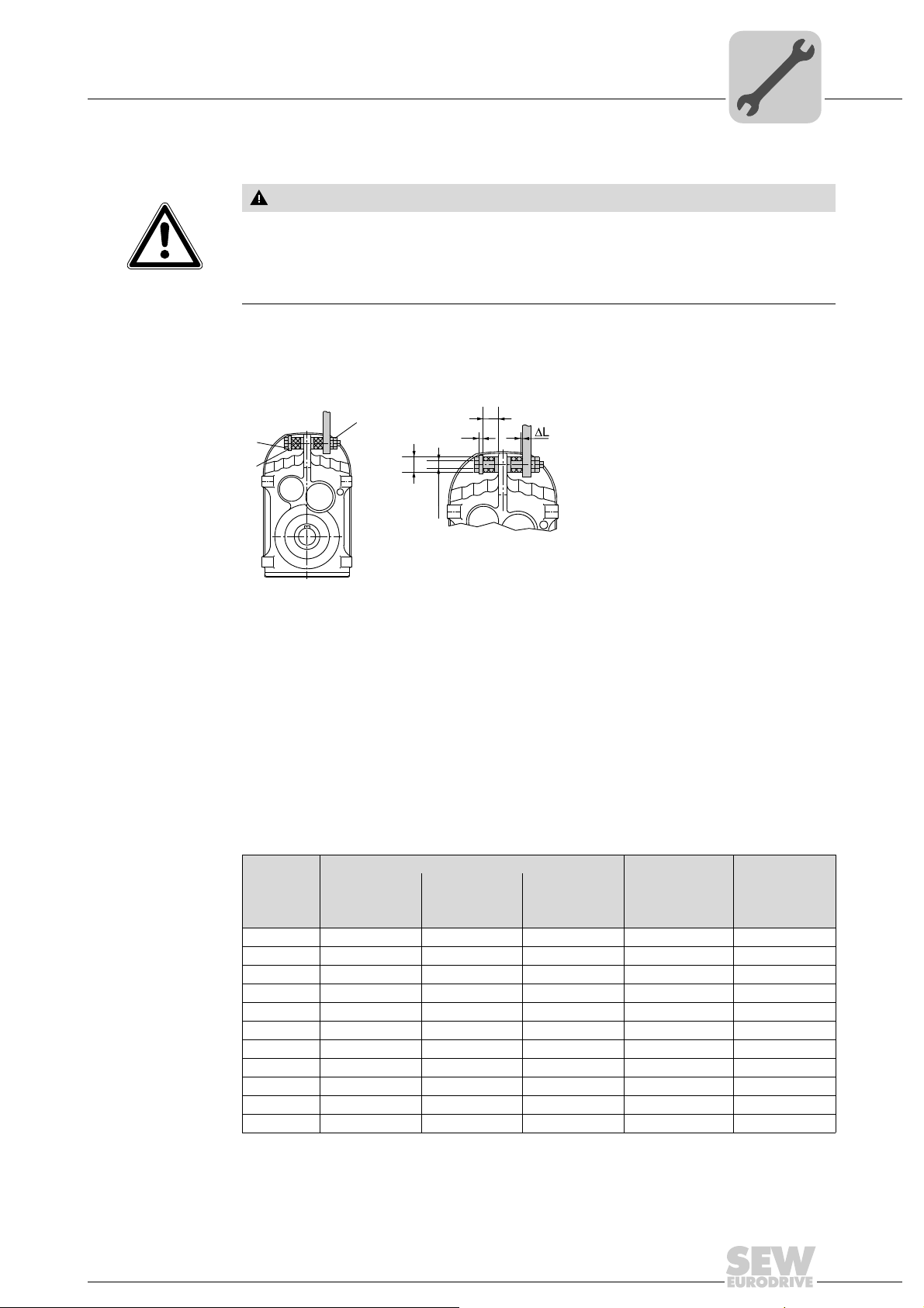
Proceed as follows to mount the rubber buffers:
1. Use screws [1] and washers according to the following table.
2. Use two nuts to secure the screw connection [3].
3. Tighten the screw until the initial stress "∆ L" of the buffers is reached according to
the table.
Rubber buffer
Gear unit
F..27 /G 40 12.5 20 5 1
F..37 /G 40 12.5 20 5 1
F..47 /G 40 12.5 20 5 1.5
F..57 /G 40 12.5 20 5 1.5
F..67 /G 40 12.5 20 5 1.5
F..77 /G 60 21.0 30 10 1.5
F..87 /G 60 21.0 30 10 1.5
F..97 /G 80 25.0 40 12 2
F..107 /G 80 25.0 40 12 2
F..127 /G 100 32.0 60 15 3
F..157 /G 120 32.0 60 15 3
Diameter Inner
diameter
d [mm] b [mm] c [mm] a [mm] [mm]
Length
(loose)
Washer width ∆ L (taut)
Assembly and Operating Instructions – Gear Units R..7, F..7, K..7, K..9, S..7, SPIROPLAN® W
29
Page 30
4
45°
[1]
Mechanical Installation
Torque arms for shaft-mounted gear units
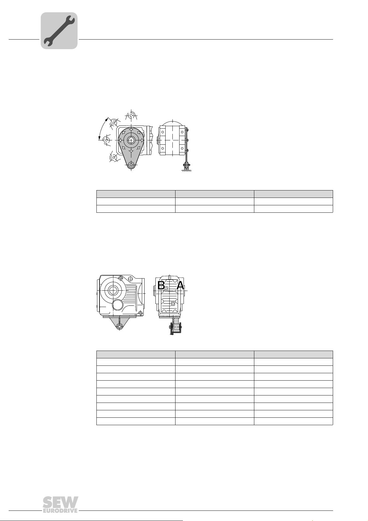
4.5.2 Helical-bevel gear units K..19 – 29
The following figure shows the torque arm for helical-bevel gear units KA19 – 29.
• Apply bearings to both sides of the bushing [1].
• Mount connection side B so that it mirrors A.
Gear unit Screws Tightening torque
K..19 /T 4 x M8 × 22 – 8.8 25 Nm
K..29 /T 4 x M8 × 22 – 8.8 25 Nm
7717631499
4.5.3 Helical-bevel gear units K..37 – 157
The following figure shows the toque arm for helical-bevel gear units.
• Apply bearings to both sides of the bushing [1].
• Mount connection side B so that it mirrors A.
Gear unit Screws Tightening torque
K..37 /T 4 × M10 × 25 – 8.8 48 Nm
K..47 /T 4 × M10 × 30 – 8.8 48 Nm
K..67 /T 4 × M12 × 35 – 8.8 86 Nm
K..77 /T 4 × M16 × 40 – 8.8 210 Nm
K..87 /T 4 × M16 × 45 – 8.8 210 Nm
K..97 /T 4 × M20 × 50 – 8.8 410 Nm
K..107 /T 4 × M24 × 60 – 8.8 710 Nm
K..127 /T 4 × M36 × 130 – 8.8 2.500 Nm
K..157 /T 4 × M36 × 130 – 8.8 2.500 Nm
[1]
211362059
30
Assembly and Operating Instructions – Gear Units R..7, F..7, K..7, K..9, S..7, SPIROPLAN® W
Page 31

4.5.4 Helical-worm gear units
[1]
45˚
[1]
The following figure shows the torque arm for helical-worm gear units.
• Apply bearings to both sides of the bushing [1].
Mechanical Installation
Torque arms for shaft-mounted gear units
211491723
4
4.5.5 SPIROPLAN
Gear unit Screws Tightening torque
S..37 /T 4 x M6 × 16 – 8.8 11 Nm
S..47 /T 4 x M8 × 20 – 8.8 25 Nm
S..57 /T 6 x M8 × 20 – 8.8 25 Nm
S..67 /T 4 x M12 × 25 – 8.8 86 Nm
S..77 /T 8 x M12 × 35 – 8.8 86 Nm
S..87 /T 8 x M16 × 35 – 8.8 210 Nm
S..97 /T 8 x M16 × 35 – 8.8 210 Nm
®
W gear units
®
The following figure shows the toque arm for SPIROPLAN
W gear units.
• Apply bearings to both sides of the bushing [1].
211489547
Gear unit Screws Tightening torque Nm
W..10 /T 4 x M6 × 16 - 8.8 11
W..20 /T 4 x M6 × 16 - 8.8 11
W..30 /T 4 x M6 × 16 - 8.8 11
W..37 /T 4 x M8 × 20 - 8.8 25
W..47 /T 4 x M10 × 25 - 8.8 48
Assembly and Operating Instructions – Gear Units R..7, F..7, K..7, K..9, S..7, SPIROPLAN® W
31
Page 32

4
NOCO
FLUI
®
N
OC
O
FLU
I
®
A
[1]
[2]
[3]
[4]
[5]
Mechanical Installation
Shaft-mounted gear units with keyway or splined hollow shaft
4.6 Shaft-mounted gear units with keyway or splined hollow shaft
INFORMATION
Concerning the configuration of the customer shaft, please also refer to the design
notes in the gearmotors catalog.
4.6.1 Installation notes
®
1. Apply NOCO
fluid and thoroughly spread it.
2. Install the shaft and secure it axially
(installation is facilitated by using a mounting device).
Following a description of the three mounting types:
• 2A: Standard scope of delivery
• 2B: Installation/removal kit for customer shaft with contact shoulder
• 2C: Installation/removal kit for customer shaft without contact shoulder
2A: Installation with standard scope of delivery
211516171
211518347
[1] Short retaining screw (standard scope of delivery)
[2] Lock washer
[3] Washer
[4] Retaining ring
[5] Customer shaft
32
Assembly and Operating Instructions – Gear Units R..7, F..7, K..7, K..9, S..7, SPIROPLAN® W
Page 33

Mechanical Installation
B
C
Shaft-mounted gear units with keyway or splined hollow shaft
2B: Installation with SEW-EURODRIVE installation and removal kit (page 37)
– Customer shaft with contact shoulder
[1]
[2]
[3]
[4]
[5]
211520523
[1] Retaining screw
[2] Lock washer
[3] Washer
[4] Retaining ring
[5] Customer shaft with contact shoulder
4
2C: Installation with SEW-EURODRIVE installation and removal kit (page 37)
– Customer shaft without contact shoulder
[1]
[2]
[3]
[4]
[5]
[6]
211522699
[1] Retaining screw
[2] Lock washer
[3] Washer
[4] Retaining ring
[5] Spacer
[6] Customer shaft without contact shoulder
Assembly and Operating Instructions – Gear Units R..7, F..7, K..7, K..9, S..7, SPIROPLAN® W
33
Page 34

4
Mechanical Installation
Shaft-mounted gear units with keyway or splined hollow shaft
3. Tighten the retaining screw to the appropriate torque (see table).
211524875
Screw Tightening torque [Nm]
M5 5
M6 8
M10/12 20
M16 40
M20 80
M24 200
INFORMATION
To avoid contact corrosion, we recommend that the customer shaft should additionally
be lathed down between the 2 contact surfaces.
34
Assembly and Operating Instructions – Gear Units R..7, F..7, K..7, K..9, S..7, SPIROPLAN® W
Page 35

Shaft-mounted gear units with keyway or splined hollow shaft
[1]
[2]
[3]
[4]
[5]
[6]
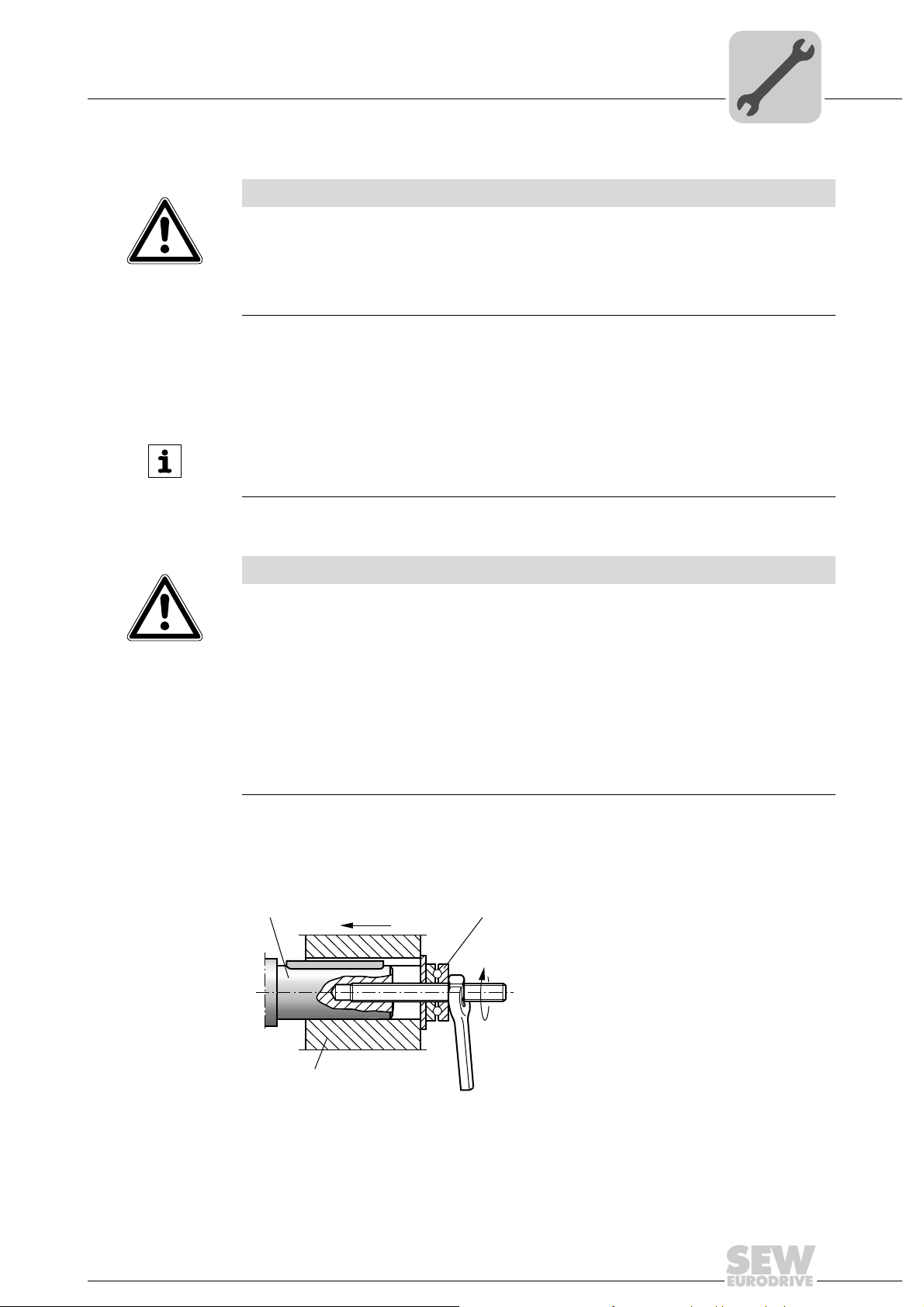
4.6.2 Information about disassembly
This description is only applicable when the gear unit was assembled using the installatio/removal kit (page 37) from SEW-EUROD RIVE. Observe section "Installation notes
(page 32)", 2B or 2C.
1. Loosen the retaining screw [1].
2. Remove parts [2] to [4] and, if fitted, the spacer tube [5].
Mechanical Installation
4
211527051
[1] Retaining screw
[2] Lock washer
[3] Washer
[4] Retaining ring
[5] Spacer
[6] Customer shaft
3. Insert the forcing disc [8] and the fixed nut [7] from the SEW-EURODRIVE installation/removal kit between the customer shaft [6] and the circlip [4].
4. Re -install the retaining ring [4].
Assembly and Operating Instructions – Gear Units R..7, F..7, K..7, K..9, S..7, SPIROPLAN® W
35
Page 36

4
[1]
[4]
[7]
[8]
[6]
Mechanical Installation
Shaft-mounted gear units with keyway or splined hollow shaft
5. Screw the retaining screw [1] back in. Now you can force the gear unit off the shaft
by tightening the screw.
211529227
[1] Retaining screw
[4] Retaining ring
[6] Customer shaft
[7] Fixed nut
[8] Forcing disk
36
Assembly and Operating Instructions – Gear Units R..7, F..7, K..7, K..9, S..7, SPIROPLAN® W
Page 37

Shaft-mounted gear units with keyway or splined hollow shaft
[1]
[8]
[7]
[7]
[1]
4.6.3 SEW installation and removal kit
The SEW-EURODRIVE installation/removal kit can be ordered by quoting its part
number.
Mechanical Installation
4
211531403
[1] Retaining screw
[7] Fixed nut for disassembly
[8] Forcing disk
-0.5
-0.5
Type DH7
WA..10 16 M5 5 5 12 4.5 18 15.7 50 643 712 5
WA..20 18 M6 5 6 13.5 5.5 20.5 17.7 25 643 682 X
WA..20, WA..30, SA..37, WA..37, KA..19 20 M6 5 6 15.5 5.5 22.5 19.7 25 643 683 8
FA..27, SA..47, WA..47, KA..29 25 M10 5 10 20 7.5 28 24.7 35 643 684 6
FA..37, KA..37, SA..47, SA..57, WA..47, KA..29 30 M10 5 10 25 7.5 33 29.7 35 643 685 4
FA..47, KA..47, SA..57 35 M12 5 12 29 9.5 38 34.7 45 643 686 2
FA..57, KA..57, FA..67, KA..67, SA..67 40 M16 5 12 34 11.5 41.9 39.7 50 643 687 0
SA..67 45 M16 5 12 38.5 13.5 48.5 44.7 50 643 688 9
FA..77, KA..77, SA..77 50 M16 5 12 43.5 13.5 53.5 49.7 50 643 689 7
FA..87, KA..87, SA..77, SA..87 60 M20 5 16 56 17.5 64 59.7 60 643 690 0
FA..97, KA..97, SA..87, SA..97 70 M20 5 16 65.5 19.5 74.5 69.7 60 643 691 9
FA..107, KA..107 80 M20 5 20 75.5 21.5 85 79.7 70 106 8211 2
FA..107, KA..107, SA..97 90 M24 5 20 80 24.5 95 89.7 70 643 692 7
FA..127, KA..127 100 M24 5 20 89 27.5 106 99.7 70 643 693 5
FA..157, KA..157 120 M24 5 20 107 31 127 119.7 70 643 694 3
1) Retaining screw
[mm]
M1)C4
[mm]
C5
[mm]
C6
[mm]
U
[mm]
T
[mm]
-0.5
D3
[mm]
[mm]
L4
Part number of
installation/
removal kit
Assembly and Operating Instructions – Gear Units R..7, F..7, K..7, K..9, S..7, SPIROPLAN® W
37
Page 38

4
Mechanical Installation
Shaft-mounted gear units with keyway or splined hollow shaft
INFORMATION
The SEW installation kit for attaching the customer shaft is a recommendation by
SEW-EURODRIVE. You must always check whether this design can compensate the
axial loads. In particular applications (e.g. mounting mixer shafts), a different design
may have to be used to secure the shaft axially. In these cases, customers can use
their own devices. However, you must ensure that these designs do no t cause p otential sources of combustion according to DIN EN 13463 (for example, impact sparks).
38
Assembly and Operating Instructions – Gear Units R..7, F..7, K..7, K..9, S..7, SPIROPLAN® W
Page 39

Shaft-mounted gear units with shrink disk
4.7 Shaft-mounted gear units with shrink disk
4.7.1 Assembly notes
NOTICE
Tightening the screws without installed shaft may result in the hollow shaft being
deformed.
Possible damage to property
• Only tighten the locking screws with the shaft installed.
1. Loosen the locking screws by a few turns (do not unscrew them completely!).
Mechanical Installation
4
AB
211533579
2. Carefully degrease the hollow shaft hole and the input shaft using a commercially
available solvent.
211535755
Assembly and Operating Instructions – Gear Units R..7, F..7, K..7, K..9, S..7, SPIROPLAN® W
39
Page 40

4
Mechanical Installation
Shaft-mounted gear units with shrink disk
3. Ho llow shaft/input shaft after degreasing.
211537931
®
4. Apply NOCO
It is essential to make sure that the clamping area of the shrink disk is free from
grease. Never apply NOCO
may be able to get into the clamping area of the shr ink disk when the input shaft is
put on.
fluid to the input shaft in the area of the bushing.
®
fluid directly to the bushing. This is because the paste
40
211540107
Assembly and Operating Instructions – Gear Units R..7, F..7, K..7, K..9, S..7, SPIROPLAN® W
Page 41

Mechanical Installation
Shaft-mounted gear units with shrink disk
5. Install the input shaft.
– Make sure that the locking collars of the sh rink disk are installed in parallel to each
other.
– For gear unit housings with shaft shoulder:
Mount the shrink disk onto the stop on the shaft shoulder.
– For gear unit housings without shaft shoulder:
Install the shrink disk with a 1 to 2 mm distance from the gear unit housing.
– Tighten the locking screws by working round with the torque wrench seve ral times
from one screw to the next (not in diametrically opposite sequence).
The exact values for the tightening torques are shown on the shrink disk.
4
1-2mm
6. After installation, make sure the remaining gap between the outer rings is > 0 mm.
7. Grease the area around the shrink disk outside the hollow shaft to prevent corrosion.
s>0mm
211542283
Assembly and Operating Instructions – Gear Units R..7, F..7, K..7, K..9, S..7, SPIROPLAN® W
41
Page 42

4
Mechanical Installation
Shaft-mounted gear units with shrink disk
4.7.2 Removal notes
4.7.3 Cleaning and lubrication
1. Loosen the locking screws one after the other by a quarter rotation to avoid tilting the
outer rings.
2. Unscrew the locking screws evenly one after the other. Do not remove the locking
screws completely.
3. Remove the shaft or pull the hub off the shaft. (Remove any rust that may have
formed between the hub and the end of the shaft beforehand.)
4. Remove the shrink disk from the hub.
There is no need to dismantle removed shrink disks before re-installing them.
Clean and lubricate the shrink disk if it is dirty.
Lubricate the tapered surfaces with one of the following solid lubricants:
Lubricant (Mo S2) Sold as
Molykote 321 (lube coat)
Molykote spray (powder spray)
Molykote G Rapid
Aemasol MO 19P
Aemasol DIO-sétral 57 N (lube coat)
Spray
Spray
Spray or paste
Spray or paste
Spray
Grease the locking screws with a multipurpose grease such as Molykote BR 2 or similar.
42
Assembly and Operating Instructions – Gear Units R..7, F..7, K..7, K..9, S..7, SPIROPLAN® W
Page 43

Mechanical Installation
NO
CO
FL
UID
®
Shaft-mounted gear units with TorqLOC
®
4
4.8 Shaft-mounted gear units with TorqLOC
®
4.8.1 Installation notes for customer shaft without contact shoulder
1. Clean the customer shaft and the inside of the hollow sha ft. Ensure that all traces of
grease or oil are removed.
2. Install the stop ring and the bushing on the customer shaft.
211941003
3. Mount the torque arm to the drive unit, observe chapter "Torque arms for shaftmounted gear units" (page 29).
5128549131
®
4. Apply NOCO
fluid on the bushing and spread it thoroughly.
211938827
Assembly and Operating Instructions – Gear Units R..7, F..7, K..7, K..9, S..7, SPIROPLAN® W
43
Page 44

4
K..7
S.. / W.. / K..9
F..
Mechanical Installation
Shaft-mounted gear units with TorqLOC
5. Push the gear unit onto the customer shaft.
9007199466677643
6. Preassemble the torque arm (do not tighten the screws).
®
7. Push the busing onto the gear unit up to the stop.
9007199466686347
9007199466684171
44
Assembly and Operating Instructions – Gear Units R..7, F..7, K..7, K..9, S..7, SPIROPLAN® W
Page 45

Mechanical Installation
Shaft-mounted gear units with TorqLOC
8. Se cure the bushin g with the stop ring . Tigh ten the split ring on the bushing using the
appropriate torque as specified in the following table:
9007199466741899
®
4
Type Nickel-plated
[Standard]
KT / FT ST / WT Torque in Nm
-37 18 7.5
37 47 18 7.5
47 57 18 7.5
57, 67 67 35 18
77 77 35 18
87 87 35 18
97 97 35 18
107 – 38 38
127 – 65 65
157 – 150 150
Stainless steel
9. Make sure that all screws are loosened and slide the shrink disk onto the hollow
shaft.
9007199466744075
Assembly and Operating Instructions – Gear Units R..7, F..7, K..7, K..9, S..7, SPIROPLAN® W
45
Page 46

4
Mechanical Installation
Shaft-mounted gear units with TorqLOC
10.Slide the counter bushing onto the customer shaft and into the hollow shaft
®
CO
NO
FLUID
9007199466746251
11.until the shrink disk is properly seated.
12.Tap lightly on the flange of the counter bushing to ensure that the socket is fitted
securely in the hollow shaft.
®
9007199466748427
13.Make sure that the customer shaft is seated in the counter bushing.
9007199466750603
46
Assembly and Operating Instructions – Gear Units R..7, F..7, K..7, K..9, S..7, SPIROPLAN® W
Page 47

Mechanical Installation
> 0 mm
s
> 0 mm
> 0 mm
Shaft-mounted gear units with TorqLOC
14.Manually tighten the screws of the shrink disk and ensure that the outer rings of the
shrink disk are parallel.
9007199466752779
15.Tighten the locking bolts by working round several times from one bolt to the next
(not in diametrically opposite sequence).
The exact values for the tightening torques are shown on the shrink disk.
®
4
> 0mm
9007199466754955
16.After installation, make su re the rem ainin g ga p be tween the outer rings is > 0 mm.
17.The remaining gap between counter bushing and hollow shaft end as well as bu shing
and stop ring must be > 0 mm.
9007201603402123
Assembly and Operating Instructions – Gear Units R..7, F..7, K..7, K..9, S..7, SPIROPLAN® W
47
Page 48

4
Mechanical Installation
Shaft-mounted gear units with TorqLOC
18.Securely tighten the torque arm; observe chapter "Torque arm for shaft-mounted
gear units" (page 29).
5129142283
®
48
Assembly and Operating Instructions – Gear Units R..7, F..7, K..7, K..9, S..7, SPIROPLAN® W
Page 49

Mechanical Installation
0 mm
Shaft-mounted gear units with TorqLOC
4.8.2 Installation notes for customer shaft with contact shoulder
1. Clean the customer shaft and the inside of the hollow sha ft. Ensure that all traces of
grease or oil are removed.
5129572875
2. Mount the torque arm to the drive unit, observe chapter "Torque arms for shaftmounted gear units" (page 29).
®
4
5128549131
3. Slide the bushing onto the customer shaft.
2349377035
Assembly and Operating Instructions – Gear Units R..7, F..7, K..7, K..9, S..7, SPIROPLAN® W
49
Page 50

4
NOCO
FL
UID
®
Mechanical Installation
Shaft-mounted gear units with TorqLOC
4. Apply NOCO® fluid on the bushing and spread it thoroughly.
2349367435
5. Push the gear unit onto the customer shaft.
®
5129650443
6. Make sure that all screws are loosened and slide the shrink disk onto the hollow
shaft.
212003083
50
Assembly and Operating Instructions – Gear Units R..7, F..7, K..7, K..9, S..7, SPIROPLAN® W
Page 51

Mechanical Installation
Shaft-mounted gear units with TorqLOC
7. Slid e the counter bushing onto the customer shaft and into the hollow shaft
®
CO
NO
FLUID
9007199466746251
8. until the shrink disk is properly seated.
9. Tap lightly on the flange of the counter bushing to ensure that the socket is fitted
securely in the hollow shaft.
®
4
9007199466748427
10.Make sure that the customer shaft is seated in the counter bushing.
9007199466750603
Assembly and Operating Instructions – Gear Units R..7, F..7, K..7, K..9, S..7, SPIROPLAN® W
51
Page 52

4
> 0mm
> 0 mm
s
> 0 mm
> 0 mm
Mechanical Installation
Shaft-mounted gear units with TorqLOC
11.Manually tighten the screws of the shrink disk and ensure that the outer rings of the
shrink disk are parallel.
9007199466752779
12.Tighten the locking bolts by working round several times from one bolt to the next
(not in diametrically opposite sequence).
The exact values for the tightening torques are shown on the shrink disk.
®
9007199466754955
13.After installation, make su re the rem ainin g ga p be tween the outer rings is > 0 mm.
14.The remaining gap between counter bushing and hollow shaft end must be > 0 m m.
9007201603402123
52
Assembly and Operating Instructions – Gear Units R..7, F..7, K..7, K..9, S..7, SPIROPLAN® W
Page 53

Mechanical Installation
Shaft-mounted gear units with TorqLOC
15.Mount the torque arm and tighten it securely; observe chapter "Torque arms for
shaft-mounted gear units" (page 29).
5129142283
®
4
Assembly and Operating Instructions – Gear Units R..7, F..7, K..7, K..9, S..7, SPIROPLAN® W
53
Page 54

4
4.8.3 Removal notes
Mechanical Installation
Shaft-mounted gear units with TorqLOC
®
CAUTION
Burns caused by hot surfaces.
Severe injuries.
• Let the units cool down before touching them.
1. Loosen the locking screws one after the other by a quarter rotation to
avoid tilting the outer rings.
212013963
2. Unscrew the locking bolts evenly one after the other.
Do not remove the locking screws completely.
3. Disma ntle the conical steel bushing.
If required, use the outer rings as pullers as follows:
– Remove all the locking screws.
– Screw the respective number of screws in the tapped holes of the shrink disk.
– Support the inner ring again st the gear unit housing.
– Pull off the conical steel bushing by tightening the screws.
4. Re move the gear unit from the shaft.
54
2903780235
5. Remove the shrink disk from the hub.
Assembly and Operating Instructions – Gear Units R..7, F..7, K..7, K..9, S..7, SPIROPLAN® W
Page 55

4.8.4 Cleaning and lubrication
There is no need to dismantle removed shrink disks before re-installing them.
Clean and lubricate the shrink disk if it is dirty.
Lubricate the tapered surfaces with one of the following solid lubricants:
Lubricant (Mo S2) Sold as
Molykote 321 (lube coat) Spray
Molykote spray (powder spray) Spray
Molykote G Rapid Spray or paste
Aemasol MO 19P Spray or paste
Aemasol DIO-sétral 57 N (lube coat) Spray
Grease the locking screws with a multipurpose grease such as Molykote BR 2 or similar.
4.9 Installing the protective cover
Mechanical Installation
Installing the protective cover
4
CAUTION
During operation, output components are in fast motion.
Risk of jamming and crushing.
• Disconnect the motor from the power supply before starting work and safeguard it
against accidental startup.
• Cover input and output components with a touch guard.
4.9.1 Installing the rotating cover
1
1. Slid e the rotating cover onto the shrink disk until it snaps in.
Assembly and Operating Instructions – Gear Units R..7, F..7, K..7, K..9, S..7, SPIROPLAN® W
55
Page 56

4
1
2
4.9.2 Installing the fixed cover
4.9.3 Installation without cover
Mechanical Installation
Installing the protective cover
1. To fasten the cover, remove the plastic plug on the gear unit housing (see figure 1)
2. Use the delivered screws to mount the cover to the gear unit housing (see figure 2).
In certain individual cases (e.g. through-shaft), you cannot install the cover. In such
cases, the cover is not necessary if the system or unit manufacturer provides corresponding components to guarantee compliance with the required degree of protection.
If this results in additional maintenance, you have to describe this in the operating instructions for the system/component.
56
Assembly and Operating Instructions – Gear Units R..7, F..7, K..7, K..9, S..7, SPIROPLAN® W
Page 57

4.10 Coupling of AM adapters
4.10.1 IEC adapter AM63 - 280 / NEMA adapter AM56 - 365
Mechanical Installation
Coupling of AM adapters
4
9007199466840971
[1] Motor shaft
[479] Coupling half
[481] Setscrew
[484] Key
[491] Spacer tube
1. Clean the motor shaft and flange surfaces of the motor and the adapter.
2. Remove the key from the motor shaft and replace it wit h t he su p plied key [484] (not
AM63 and AM250).
3. Heat the coupling half [479] to approx. 80 - 100 °C and push the coupling half onto
the motor shaft. Position as follows:
– IEC adapter AM63 - 225 up to stop at motor shaft shoulde r.
– IEC adapter AM250 - 280 to dimension A.
– NEMA adapter with spacer tube [491] to dimension A.
4. Secure the key and coupling half using the setscrew [481] and tightening torque T
according to the table on the motor shaft.
A
Assembly and Operating Instructions – Gear Units R..7, F..7, K..7, K..9, S..7, SPIROPLAN® W
57
Page 58

4
Mechanical Installation
Coupling of AM adapters
5. Check the dimension A.
6. Seal the contact surfaces between the adapter and motor using a suitable sealing
compound.
7. M ount the motor on the ad apter. Ensure that the couplin g cla ws of the ad apte r sh aft
are engaged in the plastic cam ring.
IEC AM 63 / 71 80 / 90 100 / 112 132 160 / 180 200 225 250 / 280
A 24.5 31.5 41.5 54 76 78.5 93.5 139
T
A
Thread M4 M4 M6 M6 M8 M10 M10 M10
NEMA AM 56 143 / 145 182 / 184 213 / 215 254 / 256 284 / 286 324 / 326 364 / 365
A 46 43 55 63.5 78.5 85.5 107 107
T
A
Thread M4 M4 M6 M6 M8 M10 M10 M10
1.5 1.5 4.8 4.8 10 17 17 17
1.5 1.5 4.8 4.8 10 17 17 17
NOTE
To avoid contact corrosion, we recommend applying NOCO® Fluid to the motor shaft
before mounting the coupling half.
CAUTION
Dampness might enter the adapter when mounting a motor to the adapter.
Possible damage to property
• Seal adapter with anaerobic fluid seal.
58
Assembly and Operating Instructions – Gear Units R..7, F..7, K..7, K..9, S..7, SPIROPLAN® W
Page 59

4.10.2 Permitted loads
Mechanical Installation
Coupling of AM adapters
CAUTION
Impermissibly high loads may occur when mounting a motor.
Potential damage to property
• The load data specified in the following table are not to be exceeded.
X
Fq
18513419
4
Gear unit series R..7, F..7, K..7, K..9, and S..7:
Adapter type F
IEC NEMA x1) [mm] IEC adapter NEMA adapter
AM63/71 AM56 77 530 410
AM80/90 AM143/145 113 420 380
AM100/112 AM182/184 144 2000 1760
2)
AM132
AM132.. AM213/215 4700 3690
AM160/180 AM254/286 251 4600 4340
AM200/225 AM324-AM365 297 5600 5250
AM250/280 - 390 11200 –
1) The maximum permitted weight of the attached motor F
gravity distance x increases. If this distance is reduced, the maximum permitted weight F
increased.
2) Diameter of the adapter output flange: 160 mm
AM213/2152
Gear unit series SPIROPLAN
Adapter type F
IEC NEMA x1) [mm] IEC adapter NEMA adapter
AM63/71 AM56 115 140 120
AM80/90 AM143/145 151 270 255
2)
186
®
W37 – W47:
1600 1250
must be reduced linearly as the center of
qmax
1)
[N]
q
1)
[N]
q
cannot be
qmax
1) The maximum permitted weight of the attached motor F
gravity distance x increases. If this distance is reduced, the maximum permitted weight F
increased.
must be reduced linearly as the center of
qmax
Assembly and Operating Instructions – Gear Units R..7, F..7, K..7, K..9, S..7, SPIROPLAN® W
cannot be
qmax
59
Page 60

4
Mechanical Installation
Coupling of AM adapters
4.10.3 AM adapter with AM../RS backstop
Check the direction of rotation of the drive prior to assembly or startup. Inform the SEWEURODRIVE service in the case of incorrect direction of rotation.
The backstop is maintenance-free in operation, and does not require any further maintenance work. Backstops have a minimum lift-off speed de pendin g on the size (see following table).
.
CAUTION
If the actual speed level is below the minimum lift-off speed level, the backstops are
subject to wear and the resulting friction causes the temperature to increase.
Possible damage to property
• In rated operation, the lift-off speeds must not drop below the minimum values.
• During startup or braking, the lift-off spee ds m ay dr op below th e min i mum leve ls.
Type
AM80/90/RS,
AM143/145/RS
AM100/112/RS,
AM182/184/RS
AM132/RS,
AM213/215/RS
AM160/180/RS,
AM254/286/RS
AM200/225/RS,
AM324-365/RS
AM250/280/RS 1950 450
Maximum locking torque of the backstop
[Nm]
65 820
425 620
850 530
1450 480
1950 450
Minimum lift-off speed
[rpm]
60
Assembly and Operating Instructions – Gear Units R..7, F..7, K..7, K..9, S..7, SPIROPLAN® W
Page 61

4.11 AQ. adapter coupling
4.11.1 AQA80 - 190 adapter / AQH80 - 190 adapter
AQA AQH
Mechanical Installation
AQ. adapter coupling
4
479
1
2
A
1 Motor shaft
2 Set screw
3 Screw
AQA = With keyway
AQH = Without keyway
479
1
3
A
212114955
1. Clean the motor shaft and flange surfaces of the motor and the adapter.
2. Type AQH: Loosen the scr ews of the coupling half (479) and loosen the conical connection.
3. Heat up the coupling half (80 °C – 100 °C) and slide it onto the motor shaft.
Type AQA/AQH: up to clearance "A" (see table).
Assembly and Operating Instructions – Gear Units R..7, F..7, K..7, K..9, S..7, SPIROPLAN® W
61
Page 62

4
Mechanical Installation
AQ. adapter coupling
4. Type AQH: Tighten the screws evenly in diametrically opposite sequence, working
around several times. Make sure that all the screws are tightened with the tightening
torque T
according to the following table.
A
Type AQA: Secure the coupling halves using the set screw (see table).
5. Check the position of the coupling half (clearance "A", see table).
Mount the motor onto the adapter, making sure that the claws of the two coupling
halves engage in each other. The insertion force that must be applied when joining
the two coupling halves is dissipated after final assembly, so there is no risk of any
axial load being applied to adjacent bearings.
INFORMATION
Only for AQA, not permitted for AQH: To avoid contact corrosion, we recommend
applying NOCO
®
fluid to the motor shaft before mounting the coupling half.
CAUTION
Dampness might enter the adapter when mounting a motor to the adapter.
Possible damage to property
• Seal adapter with anaerobic fluid seal.
4.11.2 Setting dimensions / tightening torques
Type Coupling size Clearance "A"
AQA /AQH 80 /1 /2 /3
AQA /AQH 100 /1 /2 39
AQA /AQH 100 /3 /4 53
AQA /AQH 115 /1 /2 62
AQA /AQH 115 /3
AQA /AQH 140 /1 /2 62
AQA /AQH 140 /3 /4
AQA /AQH 190 /1 /2 76.5
AQA /AQH 190 /3 38 100 M8 8 x M6 10 14
19
24
28
[mm]
44.5
62
74.5
Screws Tightening torque TA
[Nm]
AQA AQH AQA AQH
M5 6 x M4 2 4.1
M5 4 x M5 2 8.5
M8 8 x M5 10 8.5AQA /AQH 160 /1 74.5
62
Assembly and Operating Instructions – Gear Units R..7, F..7, K..7, K..9, S..7, SPIROPLAN® W
Page 63

4.11.3 Permitted loads
The following figure shows the permitted force application points for the permitted maximum weights:
Mechanical Installation
AQ. adapter coupling
CAUTION
Impermissibly high loads may occur when mounting a motor.
Potential damage to property
• The load data specified in the following table are not to be exceeded.
X
4
Fq
18513419
Motor's center of gravity
X Distance from adapter flange to the middle of
the motor
Fq Overhung load
1)
Type
AQ80 77 370
AQ100/1/2 113 350
AQ100/3/4 113 315
AQ115 113 300
AQ140/1/2 144 1550
AQ140/3 144 1450
AQ160 144 1450
AQ190/1/2; Ø flange: 160 186 1250
AQ190/3; Ø flange: 160 186 1150
AQ190/1/2 186 3750
AQ190/3 186 3400
1) Maximum load values for connection screws of strength class 8.8. The maximum permitted weight of
the attached motor F
this distance is reduced, F
2) Diameter of the adapter output flange: 160 mm
must be reduced linearly as the center of gravity distance x increases. When
qmax
cannot be increased.
qmax
x
[mm]
F
[N]
1)
q
Assembly and Operating Instructions – Gear Units R..7, F..7, K..7, K..9, S..7, SPIROPLAN® W
63
Page 64

4
4.12 EWH adapters
4.12.1 Adapter EWH01 – 03
Mechanical Installation
EWH adapters
[479]
[229]
[230]
60°
[1]
4557485195
[1] Motor shaft
[229] Clamping screws
[230] Motor shaft sleeve
[479] Coupling half
1. Cle an and de-gre ase the hollow shaft hole of the coupling half [479], the motor shaft
sleeve [230], and the motor shaft [1].
2. Insert the motor shaft sleeve [230] into the coupling half [479] so that the slot of the
motor shaft sleeve [230] is at a 60° angle to the two clamping screws [229].
3. Push the coupling half [479] until it reaches the shoulder of the motor shaft.
4. T ighten the clamping screws [229] o ne after the ot her with a suitable tor que wrench ,
first to 25% of the tightening torque specified in the following table.
5. Then, tighten the two clamping screws [229] to the full, specified tightening torque.
Adapter type Motor shaft
diameter
in mm in Nm in mm
EWH01 925.63
EWH01 11 2 10 4
EWH02 11; 14; 16 2 10 4
EWH03 11; 14; 16 2 10 4
Number of
clamping screws
Tightening torque of
the clamping screw
Wrench size
64
Assembly and Operating Instructions – Gear Units R..7, F..7, K..7, K..9, S..7, SPIROPLAN® W
Page 65

4.12.2 Permitted loads
The following figure shows the permitted force application points for the permitted maximum weights:
Mechanical Installation
EWH adapters
CAUTION
Impermissibly high loads may occur when mounting a motor.
Potential damage to property
• The load data specified in the following table are not to be exceeded.
X
4
Fq
18513419
Motor's center of gravity
X Distance from adapter flange to the middle of
the motor
Fq Overhung load
1)
Type
EWH01 113 40
EWH02 120 56
EWH03 120 56
1) Maximum load values for connection screws of strength class 8.8. The maximum permitted weight of
the attached motor F
this distance is reduced, F
2) Diameter of the adapter output flange: 160 mm
must be reduced linearly as the center of gravity distance x increases. When
qmax
cannot be increased.
qmax
x
[mm]
F
[N]
1)
q
Assembly and Operating Instructions – Gear Units R..7, F..7, K..7, K..9, S..7, SPIROPLAN® W
65
Page 66

4
Mechanical Installation
AD input shaft assembly
4.13 AD input shaft assembly
Observe section "Assembling the input and output compone nts" (page 27) when installing input components.
4.13.1 AD../P – cover with motor mounting platform
Mounting the motor and adjusting the moto r mou nt i ng pl at fo rm .
212119307
[1] Motor mounting platform
[2] Stud bolt (only AD6/P / AD7/P)
[3] Support (only AD6/P / AD7/P)
[4] Nut
[5] Threaded column
1. Se t the motor mounting platform to the required mounting po sition by evenly tightening the adjusting nuts. Remove the lifting eyebolt from helical gear units in order to
achieve the lowest adjustment position. Touch up any damage to the paint work.
2. Align the motor on the motor mounting platform (shaft ends must be in alignment)
and secure it.
3. Mount the input elements on the input shaft end and the motor shaft, line them up
with one another and correct the motor position again, if necessary.
4. Put on the traction elements (V-belt, chain, etc.) and apply a preload by evenly adjusting the motor mounting platform. Do not stress the motor mounting platform and
the columns against each other when doing this.
5. Tighten all the nuts not used for adjustment in order to fix the threaded columns.
66
Assembly and Operating Instructions – Gear Units R..7, F..7, K..7, K..9, S..7, SPIROPLAN® W
Page 67

Mechanical Installation
AD input shaft assembly
4.13.2 Only AD6/P and AD7/P
Unscrew the nuts on the stud bolts before adjustment to allow the stud bolts to move
axially in the support without restriction. Do not tighten the nuts until the final adjustment
position has been reached. Do not adjust the motor mounting p latform using the support.
4.13.3 AD../ZR input shaft assembly with centering shoulder
Mounting applications on the input shaft assembly with centering shoulder.
1. Retaining bolts of a suitable length must be used to secure the application. The
length l of the new bolts is calculated as follows:
4
212121483
[l] t+a
[t] Screw-in depth (see table)
[a] Thickness of the application
[s] Retaining thread (see table)
Round down the calculated screw length to the next smaller standard length.
2. Remove the retaining screws from the centering shoulder.
3. Clean the contact surface and the centering shoulder.
Assembly and Operating Instructions – Gear Units R..7, F..7, K..7, K..9, S..7, SPIROPLAN® W
67
Page 68

4
Mechanical Installation
AD input shaft assembly
4. Cle an the thr eads of th e new bolts and ap pl y a bolt locking compound (e.g. Loctite
243) to the first few threads.
5. Attach the ap plication to the centering shoulder and tighten the retaining screws with
the specified tightening torque T
Screw-in
Type
AD2/ZR 25,5 M8 25
AD3/ZR 31,5 M10 48
AD4/ZR 36 M12 86
AD5/ZR 44 M12 86
AD6/ZR 48,5 M16 210
AD7/ZR 49 M20 410
AD8/ZR 42 M12 86
depth
t [mm]
(see table).
A
Retaining thread
s
Tightening torque
for connection screws of strength class
T
A
8.8 [Nm]
®
68
Assembly and Operating Instructions – Gear Units R..7, F..7, K..7, K..9, S..7, SPIROPLAN® W
Page 69

Permitted loads
x
F
q
Mechanical Installation
AD input shaft assembly
NOTICE
Impermissibly high loads may occur when mounting a motor.
Potential damage to property
• The load data specified in the following table are not to be exceeded.
The following figure shows the permitted force application points for the permitted maximum weights:
4
212123659
Motor's center of gravity
X Distance from adapter flange to the middle of
the motor
Fq Overhung load
1)
Type
AD2/ZR 193 330
AD3/ZR 274 1400
2)
AD4/ZR
AD4/ZR 3300
AD5/ZR 487 3200
AD6/ZR 567 3900
AD7/ZR 663 10000
AD8/ZR 516 4300
1) Maximum load values for connection screws of strength class 8.8. The maximum permitted weight of
the attached motor F
this distance is reduced, F
2) Diameter of the adapter output flange: 160 mm
must be reduced linearly as the center of gravity distance x increases. When
qmax
cannot be increased.
qmax
x
[mm]
361
F
q
[N]
1120
1)
Assembly and Operating Instructions – Gear Units R..7, F..7, K..7, K..9, S..7, SPIROPLAN® W
69
Page 70

4
Mechanical Installation
AD input shaft assembly
4.13.4 AD../RS – cover with backstop
Check the direction of rotation of the drive prior to assembly or startup. Inform the SEWEURODRIVE service in the case of incorrect direction of rotation.
The backstop is maintenance-free in operation, and does not require any further maintenance work. Backstops have a minimum lift-off speed de pendin g on the size (see following table).
If the actual speed level is below the minimum lift-off speed level, the backstops are
subject to wear, and the resulting friction causes the temperature to increase.
Possible damage to property
• In rated operation, the lift-off speeds must not drop below the minimum values.
• During startup or braking, the lift-off spee ds m ay dr op below th e min i mum leve ls.
NOTICE
Type
AD2/RS 65 820
AD3/RS 425 620
AD4/RS 850 530
AD5/RS 1450 480
AD6/RS 1950 450
AD7/RS 1950 450
AD8/RS 1950 450
Maximum locking torque of the backstop
[Nm]
Minimum lift-off speed
[rpm]
70
Assembly and Operating Instructions – Gear Units R..7, F..7, K..7, K..9, S..7, SPIROPLAN® W
Page 71

4.14 Accessory equipment
[8]
[1] [2] [3]
[4]
[5] [6]
[7]
4.14.1 AR.. and AT.. centrifugal and friction couplings
AR.. friction
coupling
Drives with a friction coupling consist of a standard gear unit and motor/variable speed
gearmotor with an adapter installed between them. This adapter accommod ates the friction coupling. In gearmotors wit h a multi-stage gear unit, the friction co upling may be
located between the first and second gear units. On delive ry, the slip torque is set individually according to the drive specifications.
The following figure shows a drive with friction coupling and W: speed monitor
Mechanical Installation
Accessory equipment
4
1901048587
[1] Trigger cam [4] Friction lining [7] Slip hub
[2] Encoder [5] Spring washer [8] Speed monitor
[3] Driving disk [6] Slotted nut
W speed monitor:
The speed monitor is used with constant-speed gearmotors and is connected to the
encoder in the adapter.
WS slip monitor:
The slip monitor is used with the following components:
• Speed-controlled motors with speed sensor
®
• VARIBLOC
variable speed gear units
INFORMATION
For detailed information about the AR.. coupling, refer to the "Centrifugal and Friction
Couplings AR.. and AT.." operating instructions, part number 17036011/EN.
Assembly and Operating Instructions – Gear Units R..7, F..7, K..7, K..9, S..7, SPIROPLAN® W
71
Page 72

4
Mechanical Installation
Accessory equipment
AT.. hydraulic
centrifugal
coupling
Hydraulic centrifugal couplings are fluid couplings based on the Fötting er principle. They
consist of 2 hinged hemispheres with blades separated by a tight gap.
The applied torque is transmitted by the inertial force of the streaming fluid. This fluid
circulates within a closed circuit, between the pump wheel (primary side) [12] on the driving shaft (motor shaft) and the turbine wheel (secondary side) [9] on the driven shaft
(gear unit input shaft).
The following figure shows the structure of a drive with hydraulic centrifugal coupling:
[8] [9] [10] [11] [12] [14][13]
[15]
[1]
[2] [3]
[1] Gear unit [6] Extended housing com-
[2] Basic flange complete [7] Motor [12] Pump wheel
[3] Backstop (optional) [8] Filler plug [13] Elastic components
[4] Intermediate flange [9] Turbine wheel [14] Flexible connecting coupling
[5] Hydraulic centrifugal coupling [10] Coupling half [15] Fusible screw plug
[4] [5] [6] [7]
1901143691
[11] Operating fluid (hydraulic oil)
plete
INFORMATION
For detailed information about the AT .. co up lin g, re fe r t o t he "Centrifugal and Friction
Couplings AR.. and AT.." operating instructions, part number 17036011/EN.
72
Assembly and Operating Instructions – Gear Units R..7, F..7, K..7, K..9, S..7, SPIROPLAN® W
Page 73

4.14.2 Diagnostic units DUV and DUO
DUV diagnostic
unit
The DUV30A diagnostic unit evaluates vibrat ion signals using freq uency analysis methods. A micromechanical acceleration sensor is used in the unit. Data can be recorded,
processed and evaluated locally without any expert knowledge.
The DUV30A diagnostic unit is suitable for early recognition of rolling element bearing
damage or unbalance. The continuo us monitoring function represents a reliable and
cost-effective solution compared to intermittent methods.
The DUV30A has been designed as a combined sensor that ca n be us ed as norma l- or
slow-speed unit. The only differen ce is the measuring time in the firmware and the resulting frequency range.
The following figure shows the DUV30A diagnostic unit:
Mechanical Installation
Accessory equipment
4
DUO diagnostic
unit
4428331403
INFORMATION
You find more information about the evaluation unit in the "DUV30A Diagnostic Unit"
manual, part number 16710010/EN.
DUO10A comprises a diagnostic unit and a temperature sensor. The temperature sensor (PT100 or PT1000 resistance sensor) is positioned in the gear unit oil to record the
oil's temperature. The diag nostic unit uses the oil temper ature values to calculate th e
remaining service life of the oil.
The diagnostic unit records the gear unit temperature continuously and calculates the
remaining service life for the selected oil type immediately. For this purpose, the diagnostic unit must be supplied with a 24 V voltage supply. Times when the diagno stic unit
is switched off are not included in the forecast.
The following figure shows the DUO10A diagnostic unit:
4719800843
INFORMATION
You find more information on the evaluation unit in the "DUV30A Diagnostic Unit"
manual, part number 11473428/EN.
Assembly and Operating Instructions – Gear Units R..7, F..7, K..7, K..9, S..7, SPIROPLAN® W
73
Page 74

4
4.14.3 Gear unit heater for gear unit series R..7, F..7, and K..7
Mechanical Installation
Accessory equipment
Oil heating can be required in order to allow for a smooth startup in the event of a cold
start at low ambient temperatures. An oil heater is available with external or integrated
thermostat depending on the gear unit design.
The heater is screwed into the gear unit housing and is controlled via a thermostat. The
limit temperature of the heater, below which the oil must be heated, is set depending on
the respective lubricant.
The following figure shows a gear unit with heater and external thermostat:
[1]
[2]
2060553483
[1] Thermostat
[2] Heater
INFORMATION
For detailed information about the gear unit heater, r efer to the "Gear Unit Series R..7,
F..7, and K..7 – Gear Unit Heater" addendum to the operating instructions, part number 16840410/EN.
74
Assembly and Operating Instructions – Gear Units R..7, F..7, K..7, K..9, S..7, SPIROPLAN® W
Page 75

4.14.4 Flange coupling
[2] [1] [2]
[3]
Flange couplings [1] are rigid couplings for connecting 2 shafts [2].
They are suitable for operation in both directions of rotation, but cannot compen sate any
shaft misalignments.
Torque between shaft and coupling is transmitted via a cylindrical interference fit. The
two coupling halves are mounted together at their flanges. The couplings are equipped
with several disassembly bores [3] for removing the interference fit hydraulically.
Mechanical Installation
Accessory equipment
4
18014402706266635
[1] Flange coupling
[2] Customer and gear unit shaft
[3] Disassembly bores
INFORMATION
For detailed information about the flange coupling, refer to the "Gear Unit Series R..7,
F..7, K..7, S..7, and SPIROPLAN
instructions, part number 19318413/EN.
®
W – Flange Coupling" addendum to the operating
Assembly and Operating Instructions – Gear Units R..7, F..7, K..7, K..9, S..7, SPIROPLAN® W
75
Page 76

4
4.14.5 Regreasing the labyrinth seal
Output shaft The following figure shows an example of a regreasable radial labyrinth seal (taconite).
Mechanical Installation
Accessory equipment
• Single oil seal with radial labyrinth seal
• Used in very dusty environments with abrasive particles
Position of
greasing points
9007204406135947
INFORMATION
Make sure that the gear unit shaft is rotating during the regreasing process.
Regreasable sealing systems are usually equipped with taper greasin g nipples accor ding to DIN 71412 A. Regreasing must be carried out at regular intervals. The greasing
points are located near the output shaft, see following figure:
4986644747
Refilling grease Regreasable sealing systems can be refilled with lubricating grease. Use moderate
pressure to force grease into each lubrication point until new grease leaks out of the
sealing gap.
Used grease, including contaminants and sand, i s in this way presse d out of the sealing
gap.
76
Assembly and Operating Instructions – Gear Units R..7, F..7, K..7, K..9, S..7, SPIROPLAN® W
Page 77

Mechanical Installation
Oil
Oil
Accessory equipment
INFORMATION
Immediately remove the old grease that leaked out.
4
Inspection and
maintenance
intervals
Technical data
Sealing and rolling
bearing grease
Observe the following inspection and maintenance intervals for the regreasing of labyrinth seals:
Time interval What to do?
Every 3000 operating hours, at least every
6 months
Fill regreasable sealing systems with grease.
The table shows the greases recommended by SEW-EURODRIVE for an operating
temperature of -40 °C to +80 °C.
Manufacturer Grease
Fuchs Renolit CX TOM 15 OEM
Aral Aral Eural Grease EP2
Aral Aral Aralube BAB EP2
NOTE
If a customer wants to use a grease that is not listed in the above table, the customer
has to make sure that it is suitable for the intended application.
4.14.6 Oil drain valve
The gear unit is equipped with an oil drain plug as standard. An oil drain valve may be
provided as option. This valve allows for a drain pipe to be easily attached when ch anging the gear unit oil.
4984750475
Assembly and Operating Instructions – Gear Units R..7, F..7, K..7, K..9, S..7, SPIROPLAN® W
77
Page 78

4
4.14.7 Oil expansion tank
Mechanical Installation
Accessory equipment
The oil expansion tank is to compensate for oil volume variations in the system caused
by temperature fluctuations. When the gear unit temperature increases, the expansion
tank absorbs some of the increasing oil volume and feeds it back to the gear unit as the
temperature goes down. As a result, the gear unit is always completely filled with oil.
The figure shows an example of a gearmotor in mounting position M4:
4.14.8 Oil-air cooler for splash lubrication /OAC
If the thermal rating of the naturally cooled gear unit is not sufficient, an oil-air cooling
system can be used.
The cooling system is delivered without electrical wiring and piping as a complete unit
on a base frame for separate installation.
The standard scope of delivery of the cooling system includes:
• Pump with directly mounted asynchronous motor
• Oil-air heat exchanger
• Temperature switch with 2 switching points
SEW-EURODRIVE uses oil-air cooling systems for standard gear units in sizes
OAC 005 and OAC 010.
4986667147
78
Assembly and Operating Instructions – Gear Units R..7, F..7, K..7, K..9, S..7, SPIROPLAN® W
Page 79

Mechanical Installation
Accessory equipment
The following figure shows an example of a standard para llel-shaft helical gear unit n ext
to an oil-air cooler.
[5]
[2]
4
[5]
[4]
[1] Motor for pump and fan [4] Suction pipe connections
[2] Oil-air heat exchanger [5] Pressure pipe connections
[3] Temperature switch with two switching points [6] Option: Oil expansion tank connection
[6]
[4]
[3]
[1]
8981051403
INFORMATION
For more information on the cooling system, refer to the addendum to the operating
instructions "Type R..7, F..7, K..7, K..9, S..7 and SPIROPLAN
cooler for splash lubrication /OAC".
®
Gear Units: Oil-air
Assembly and Operating Instructions – Gear Units R..7, F..7, K..7, K..9, S..7, SPIROPLAN® W
79
Page 80

5
00
I
5Startup
Startup
CAUTION
Improper startup may result in damage to the gear unit.
Possible damage to property.
• Note the following:
• Before startup, check that the oil level is correct. Refer to the unit's nameplate for lubricant fill quantities.
• The oil checking and drain screws and the breather valves must be freely accessible.
• The most important technical data is provided on the nameplate. Additional data relevant for operation is available in drawings and the order confirmation.
• Ensure that all retaining screws are tight after the gear unit has been installed.
• Make sure that the orientation has not changed after tightening the mounting elements.
• Prior to startup, ensure that rotating shafts as well as couplings are equipped with
suitable protective covers.
• If an oil sight glass is used for checking the oil level, ensure that it is protected against
damage.
• It is essential that there is no open fire or risk of sparks when working on the gear unit.
• Protect the gear unit from falling objects.
• Remove transport fixtures prior to startup.
• Adhere to the safety notes in the individual chapters.
80
Assembly and Operating Instructions – Gear Units R..7, F..7, K..7, K..9, S..7, SPIROPLAN® W
Page 81

5.1 Checking the oil level
[1]
00
I
Before startup, make sure that the oil level corresponds to the mounting position. Observe section "Checking the oil level and changing the oil" (page 89).
If the gear unit is equipped with an oil sight glass, you can also determine the oil level at
the oil sight glass.
NOTICE
Damage to the gear unit due to oil leaking from the oil sight glass.
Possible damage to the unit.
• Attach a suitable protective device to exclude damage to the oil sight glass as a
result from shock or blows.
1. Observe the notes in chapter "Preliminary work regarding inspection/maintenance".
2. Check the oil level at the oil sight glass according to the following figure:
Startup
Checking the oil level
5
[1] The oil level must be within this range
3. Pr oceed as follows if the oil level is too low:
– Open the respective oil fill plug, see chapter "Inspection/maintenance for the gear
unit".
– Fill in new oil of the same type via the oil fill plug up to the mark.
– Screw in the oil fill plug.
Before startup, make sure that the oil level corresponds to the mounting position. Observe section "Checking the oil level and changing the oil" (page 89).
5.2 Pseudo-leakage at shaft seals
Due to their operating principle, seals between moving su rfaces at shaft p assages cannot be completely tight, as a lubricant film must form during operation. The lubricant film
between shaft and sealing lip keeps the development of heat and wear on the sealing
system to a minimum and ensures the intended service life. The optimum sealing pro perties are only achieved after the run-in phase.
4158756363
Assembly and Operating Instructions – Gear Units R..7, F..7, K..7, K..9, S..7, SPIROPLAN® W
81
Page 82

5
00
I
Startup
Helical-worm and SPIROPLAN® W gear units
5.3 Helical-worm and SPIROPLAN® W gear units
5.3.1 Run-in period
®
SPIROPLAN
before reaching their maximum efficiency. A separate run-in period applies for each
direction of rotation if the gear unit is operated in both directions of rotation. The table
shows the average power reduction dur ing the run-in pe riod.
Helical-worm gear
units
1-start approx. 50 ... 280 approx. 1 %
2-start approx. 20 ... 75 approx. 6%
3-start approx. 20 ... 90 approx. 3%
4-start -5-start approx. 6 ... 25 approx. 3%
6-start approx. 7 ... 25 approx. 2%
and helical-worm gear units require a running-in period of at least 48 h
Worm
i range η reduction
SPIROPLAN
gear units
®
W10 / W20 / W30 W37 / W47
i range η reduction i range η reduction
approx. 35 ... 75 approx. 15%
approx. 20 ... 35 approx. 10%
approx. 10 ... 20 approx. 8% approx. 30...70 approx. 8%
approx. 8 approx. 5% approx. 10 ... 30 approx. 5%
approx. 6 approx. 3% approx. 3...10 approx. 3%
82
Assembly and Operating Instructions – Gear Units R..7, F..7, K..7, K..9, S..7, SPIROPLAN® W
Page 83

Helical/parallel-shaft helical/helical-bevel gear units
A
B
CCW
CW
CCW
CW
00
I
5.4 Helical/parallel-shaft helical/helical-bevel gear units
No special startup instructions are required for helical, parallel-shaft he lica l and helicalbevel gear units providing the gear units have been installe d in accordance with chapter
"Mechanical Installation" (page 18).
5.5 Gear units with backstop
The purpose of a backstop is to prevent undesirable reverse rotation. During operation,
the backstop permits rotation in one specified direction of rotation only.
NOTICE
Operating the motor in the blocking direction could destroy the backstop.
Possible damage to property
• Do not start up the motor in the blocking direction. Be sure that the motor power
supply is correctly connected so that the motor rotates in the required direction.
• The backstop can be operated in blocking direction with half the output torque once
for control purposes.
Startup
5
The direction of rotation is determined with a view to the output shaft (LSS).
• Clockwise (CW)
• Counterclockwise (CCW)
The permitted direction of rotation is indicated on the housing.
Assembly and Operating Instructions – Gear Units R..7, F..7, K..7, K..9, S..7, SPIROPLAN® W
659173899
83
Page 84

5
00
I
Startup
Components made of elastomers with fluorocarbon rubber
5.6 Components made of elastomers with fluorocarbon rubber
Under normal operating conditions and at temper atures up to 200 °C, flu orocarbon ru bber is very stable and safe. However, when heated to more than 300 °C, e.g. by fire or
the flame of a cutting torch, it forms harmful gases and vapors as well as harmful residue.
CAUTION
Health risk due to dangerous gases, vapors, and residue created by heating fluorocarbon rubber to > 200 °C.
Damage to health.
• Make sure that components made of fluorocarbon rubber are not exposed to temperatures > 200 °C. Remove the components, if necessary.
• Avoid inhaling fluorocarbon rubber gases and vapors as well as skin and eye
contact at all costs.
• Avoid contact with the cooled-down fluorocarbon rubber, a s dangerous residue has
formed it was heated.
®
The following components of R..7, F..7, K..7, K..9, S..7 , and SPIROPLAN
can contain elastomers made of fluorocarbon rubber.
• Oil seals
• Breather valve
• Screw plugs
The user is responsible for safe handling during the service life including eco-friendly
disposal.
SEW-EURODRIVE is not responsible for damage caused by improper handling.
W gear units
84
Assembly and Operating Instructions – Gear Units R..7, F..7, K..7, K..9, S..7, SPIROPLAN® W
Page 85

Inspection/Maintenance
Preliminary work regarding gear unit inspection/maintenance
6 Inspection/Maintenance
The following gear units are lubricated for life:
• Helical gear units R07, R17, R27
• Parallel-shaft helical gear units F27
®
• SPIROPLAN
Depending on external factors, the surface/corrosion protection might have to be
repaired or renewed.
6.1 Preliminary work regarding gear unit inspection/maintenance
Observe the following notes before you start with inspection/maintenance work.
WARNING
Risk of crushing if the drive starts up unintentionally.
Severe or fatal injuries.
• Disconnect the gearmotor from the power supply before starting work and protect
it against unintentional re-start.
gear units
6
WARNING
Danger of burns due to hot gear unit and hot gear unit oil.
Severe injuries.
• Let the gear unit cool down before you begin with your work.
• Only remove the oil level and oil drain plug very carefully.
NOTICE
Filling the wrong oil may result in significantly different lubricant characteristics.
Potential damage to property
• Do not mix different synthetic lubricants and do not mix synthetic with mineral lubricants.
• Mineral oil is used as standard lubricant.
NOTICE
Improper maintenance may result in damage to the gear unit.
Possible damage to property.
• Observe the notes in this chapter.
INFORMATION
The position of the oil level plug, oil drain plug a nd the b re ather valve dep end s on the
mounting position. Refer to the diagrams of the mounting positions. See section
"Mounting positions (page 104)".
Assembly and Operating Instructions – Gear Units R..7, F..7, K..7, K..9, S..7, SPIROPLAN® W
85
Page 86

6
Inspection/Maintenance
Inspection/maintenance intervals
• Strict adherence to the inspection and maintenance intervals is absolutely necessary
to ensure safe working conditions.
• Before releasing shaft connections, make sure that there are no active torsional
moments present (tensions within the system).
• Prevent foreign bodies from entering the gear unit during maintenance and inspection work.
• Do not clean the gear unit with a high-pressure cleaning system as water might enter
the gear unit and the seals might be damaged.
• Perform safety and function tests following all maintenance and repair work.
6.2 Inspection/maintenance intervals
The following table lists the obligatory intervals and the corresponding measures:
Time interval What to do?
• Every 3,000 hours of operation, at least every
6months
• Depending on the operating conditions (see illustration below), every 3 years at the latest
• according to oil temperature
• Depending on the operating conditions (see illustration below), every 5 years at the latest
• according to oil temperature
• Varying (depending on external factors) • Touch up or renew the surface/anticorrosion
• Check oil and oil level
• Check running noise for possible bearing
damage
• Visual inspection of the seals for leakage
• For gear units with a torque arm: Check and
replace the rubber buffers, if necessary
• Change mineral oil
• Replace rolling bearing grease (recommendation)
• Replace oil seal (do not install it in the same
track)
• Change synthetic oil
• Replace rolling bearing grease (recommendation)
• Replace oil seal (do not install it in the same
track)
coating
86
Assembly and Operating Instructions – Gear Units R..7, F..7, K..7, K..9, S..7, SPIROPLAN® W
Page 87

6.3 Lubricant change intervals
5000
10000
15000
20000
25000
30000
[h]
120
[°C]
110 115
100
90
80
70
0
[1]
[2]
[3]
[4]
[5]
The following figure shows the change intervals for standard gear units under normal
environmental conditions. Change the oil more frequently when using special versions
subject to more severe/aggressive environmental conditions!
Inspection/Maintenance
Lubricant change intervals
6
[1]
Operating hours
[2]
Sustained oil bath temperature
•
Average value per oil type at 70 °C
[3] CLP PG
[4] CLP HC / HCE
[5] CLP / HLP / E
Oil
Oil
Assembly and Operating Instructions – Gear Units R..7, F..7, K..7, K..9, S..7, SPIROPLAN® W
87
Page 88

6
Inspection/Maintenance
Inspection/maintenance for the AL / AM / AQ. / EWH adapter
6.4 Inspection/maintenance for the AL / AM / AQ. / EWH adapter
The following table lists the obligatory intervals and the corresponding measures:
Time interval What to do?
• Every 3 000 hours of operation, at least every
6 months
• After 10 000 hours of operation • Check torsional play
• After 25 000 - 30 000 hours of operation • Renew the rolling bearing grease
6.5 Inspection/maintenance for the AD input shaft assembly
The following table lists the obligatory intervals and the corresponding measures:
Time interval What to do?
• Every 3 000 hours of operation, at least every
6 months
• After 25 000 - 30 000 hours of operation • Renew the rolling bearing grease
• Check running noise for possible bearing
damage
• Visually check the adapter for leakage
• Visually check the elastic annular gear
• Replace oil seal (do not install it in the
same track)
• Change the elastic annular gear
• Check running noise for possible bearing
damage
• Visually check the adapter for leakage
• Replace the oil seal
88
Assembly and Operating Instructions – Gear Units R..7, F..7, K..7, K..9, S..7, SPIROPLAN® W
Page 89

Inspection/maintenance for the gear unit
6.6 Inspection/maintenance for the gear unit
6.6.1 Checking the oil level and changing the oil
The procedure when checking the oil level and changing the oil depe nds on the following
factors:
• Gear unit type
•Size
• Mounting position
Observe the references to the respective sections as well as the following table. Refer
to chapter "Mounting Positions (page 104)" for notes on the mounting positions. You
cannot check the oil level of gear units in pivoted mounting position. The gear units are
delivered with the correct oil level. Observe the designations and fill quantities on the
nameplate if you have to change the oil.
Code letter Chapter "Checking the oil level and changing the oil" Reference
A: • Helical gear units...
B: • Helical gear units...
C: • Helical-worm gear units S..37
D: • SPIROPLAN
E: • SPIROPLAN
• Parallel-shaft helical gear units...
• Helical-bevel gear units...K..37 – 187
• Helical-worm gear units... S..47 – 97
With oil level plug
• Parallel-shaft helical gear units...
• SPIROPLAN
Without oil level plug, with cover plate
• Helical-bevel gear units K..19 / K..29
Without oil level plug and cover plate
In mounting positions M1, M2, M3, M5, M6 with oil level plug
In M4 mounting position without oil level plug and cover plate
®
gear units...
®
W..37 / W..47
®
W..37 / W..47...
Inspection/Maintenance
6
(page 90)
(page 92)
(page 96)
(page 99)
(page 101)
Series Gear unit
R..07 – 27 B
R..37 / R..67 A
R
F
K K..19 / K..29 C
K K..37 – 187 A
S
W
R..47 / R..57 ABA
R..77 – 167 A
RX..57– 107 A
F..27 B
F..37 – 157 A
S..37 C
S..47 – 97 A
W..10 – 30 B
W..37 – 47 DED
Code letter for chapter "Checking the oil level and changing the oil"
M1 M2 M3 M4 M5 M6
Assembly and Operating Instructions – Gear Units R..7, F..7, K..7, K..9, S..7, SPIROPLAN® W
89
Page 90

6
Oil
Ø
Inspection/Maintenance
Inspection/maintenance for the gear unit
6.6.2 A: Helical, parallel-shaft helical, helical-bevel and helical-wo rm gear units with oil level plug
Checking the oil
level via oil level
plug
Proceed as follows to check the oil level of the gear unit:
1. Obser ve the notes in chapter "Prelim inary work regar ding gear u nit inspecti on/maintenance" (page 85).
2. De termine the position of the oil level plu g and the breather valve using the mounting
position sheets. See chapter "Mounting positions" (page 104).
3. Place a container underneath the oil level plug.
4. Slo wly remove the oil level plug. Small amounts of oil may leak out as the permitted
maximum oil level is higher than the lower edge of the oil level bore.
5. Check the oil level according to the following figure and the corresponding table.
[1]
[2]
Oil
min.
X
[1] Oil level bore
[2] Reference oil level
Oil level bore Ø Min and max fill level = x [mm]
M10 x 1 1.5
M12 x 1.5 2
M22 x 1.5 3
M33 x 2 4
M42 x 2 5
max.
X
18634635
6. Pr oceed as follows if the oil level is too low:
– Remove the breather valve.
– Fill in additional oil of the same type via the vent hole until the oil level is at the
lower edge of the oil level bore.
– Re-insert the breather valve.
90
7. Re-insert the oil level plug.
Assembly and Operating Instructions – Gear Units R..7, F..7, K..7, K..9, S..7, SPIROPLAN® W
Page 91

Inspection/Maintenance
Inspection/maintenance for the gear unit
6
Checking the oil
via oil drain plug
Changing the oil
via oil drain plug
and breather valve
Proceed as follows to check the oil of the gear unit:
1. Obser ve the notes in chapter "Prelim inary work regar ding gear u nit inspecti on/maintenance" (page 85).
2. De te rmine th e position of th e o il d rain p l ug usin g the m ountin g position shee ts. See
chapter "Mounting Positions" (page 104).
3. Remove a little oil from the oil drain plug.
4. Check the oil consistency.
– Viscosity
– If you can see that the oil is heavily contaminated, we recommend that you
change the oil even if this is outside the service intervals specified in "Inspection
and maintenance intervals" (page 86).
5. Check the oil level. See previous section.
WARNING
Risk of burns due to hot gear unit and hot gear unit oil.
Serious injuries
• Let the gear unit cool down before beginning work.
• However, the gear unit must still be warm otherwise the high viscosity of excessively cold oil will make it harder to drain the oil properly.
1. Obser ve the notes in chapter "Prelim inary work regar ding gear u nit inspecti on/maintenance" (page 85).
2. Determine the position of the oil drain plug, the oil level plug and the breather valve
using the mounting position sheets. See chapter "Mounting Positions" (page 104).
3. Place a container underneath the oil drain plug.
4. Remove the oil level plug, the breather valve and the oil drain plug.
5. Drain all of the oil.
6. Re-insert the oil drain plug.
7. Fill in new oil of the same type via the vent hole (otherwise consult the customer service). Do not mix different synthetic lubricants.
– Observe the oil fill quantities according to the specifications on the nameplate or
according to the mounting position. See chapter "Lubricant fill quantities"
(page 136).
– Check the oil level at the oil level plug.
8. Re-insert the oil level plug and the breather valve.
Assembly and Operating Instructions – Gear Units R..7, F..7, K..7, K..9, S..7, SPIROPLAN® W
91
Page 92

6
6.6.3 B: Helical, parallel-shaft helical, SPIROPLAN® gear units without oil level plug with cover plate
Checking the oil
level via cover
plate
Inspection/Maintenance
Inspection/maintenance for the gear unit
For gear units without oil level bore, the oil level is checked via the cover plate opening .
Proceed as follows:
1. Obser ve th e notes in se ctio n "Preliminar y work r egard ing ge ar unit inspecti on/ma intenance" (page 85).
2. For the cover plate to be on top, you have to set up the gear unit in the following
mounting position.
– R07 - R57 in M1 mounting position
– F27 in M3 mounting position
– W10 - W30 in M1 mounting position
3. Loosen the screws [1] of the cover plate [2] and remove the cover plate [2] and the
corresponding gasket [3] (see following figure).
[1]
[2]
[3]
18643211
4. Determine the vertical distance "x" between oil level and sealing surface of the gear
unit housing (see following figure).
90°
X
92
18646283
Assembly and Operating Instructions – Gear Units R..7, F..7, K..7, K..9, S..7, SPIROPLAN® W
Page 93

Inspection/Maintenance
Inspection/maintenance for the gear unit
5. Co mpare the determined value "x" to the max. distance (depen ding on the mounting
position) between the oil level and the sealing surface of the gear unit housing as
specified in the following table. Adjust the fill level if required.
6
Gear unit type Max. distance x [mm] between oil level and sealing surface of the gear
M1 M2 M3 M4 M5 M6
R07
R17
R27
R47
R57
F27
2-stage 52 ± 1 27 ± 1 27 ± 1 27 ± 1 27 ± 1 27 ± 1
3-stage 49 ± 1 21 ± 1 21 ± 1 21 ± 1 21 ± 1 21 ± 1
2-stage 63 ± 1 18 ± 1 46 ± 1 18 ± 1 46 ± 1 46 ± 1
3-stage 58 ± 1 11 ± 2 40 ± 2 11 ± 2 40 ± 2 40 ± 2
2-stage 74 ± 1 22 ± 1 45 ± 1 22 ± 1 45 ± 1 45 ± 1
3-stage 76 ± 1 19 ± 1 42 ± 1 19 ± 1 42 ± 1 42 ± 1
2-stage – – – – 39 ± 1 –
3-stage – – – – 32 ± 1 –
2-stage – – – – 32 ± 1 –
3-stage – – – – 28 ± 1 –
2-stage 78 ± 1 31 ± 1 72 ± 1 56 ± 1 78 ± 1 78 ± 1
3-stage 71 ± 1 24 ± 1 70 ± 1 45 ± 1 71 ± 1 71 ± 1
W10 12 ± 1
W20 19 ± 1
W30 31 ± 1
unit housing for mounting position
independent of the mounting position
Assembly and Operating Instructions – Gear Units R..7, F..7, K..7, K..9, S..7, SPIROPLAN® W
93
Page 94

6
Inspection/Maintenance
Inspection/maintenance for the gear unit
6. Close the gear unit after the oil level check:
• Re-attach the gasket of the cover plate. Make sure tha t the sea ling sur faces ar e
clean and dry.
• Screw on the cover plate. Tighten the cover screws with the rated tightening
torque according to the following table from the inside to the outside in the order
illustrated in the figure. Repeat the tightening procedure until the screws are properly tightened. To prevent the cover plate from being damaged, use only impulse
drivers or torque wrenches (no impact screwdrivers).
78
1
65
3
21
43
56
2
1
4
34
2
68
7
12
4
35
2
3
5
4
A BCDE
18649739
Gear unit
type
R/RF07 E M5 6 4
R/RF17/27 D
F27 B
W10 C M5 6 4
W20 C
W30 A
Image Retaining
thread
M6 11 7R/RF47/57 A
M6 11 7
Rated tightening torque TN
[Nm]
Minimum tightening torque
[Nm]
T
min
1
94
Assembly and Operating Instructions – Gear Units R..7, F..7, K..7, K..9, S..7, SPIROPLAN® W
Page 95

Inspection/Maintenance
Inspection/maintenance for the gear unit
6
Checking the oil
via cover plate
Changing the oil
via cover plate
Proceed as follows to check the oil of the gear unit:
1. Obser ve the notes in chapter "Prelim inary work regar ding gear u nit inspecti on/maintenance" (page 85).
2. Open the cover plate of the gear unit according to section "Checking the oil via the
cover plate" (page 92).
3. Take an oil sample via the cover plate opening.
4. Check the oil consistency.
– Viscosity
– If you can see that the oil is heavily contaminated, we recommend that you
change the oil even if this is outside the service intervals specified in "Inspection
and maintenance intervals" (page 86).
5. Ch eck the oil level. See section "Checking the oil level via the cover plate" (page 92).
6. Scr ew on the cover plate. Observe the order a nd the tightening torq ues according to
section "Checking the oil level via the cover plate" (page 92)
WARNING
Risk of burns due to hot gear unit and hot gear unit oil.
Serious injuries
• Let the gear unit cool down before beginning work.
• The gear unit must still be warm otherwise the high viscosity of excessively cold oil
will make it harder to drain the oil properly.
1. Obser ve the notes in chapter "Prelim inary work regar ding gear u nit inspecti on/maintenance" (page 85).
2. Ope n the cover plate of the gear unit accordin g to chapter "Checking the oil level via
the cover plate".
3. Co mpletely drain the oil into a container via the cover plate opening.
4. Fill in new oil of the same type via the cover plate opening (otherwise consult customer service). Do not mix different synthetic lubricants.
– Pour in the oil in accordance with the mounting position or as specified on the
nameplate. See chapter "Lubricant fill quantities" (page 136).
5. Check the oil level.
6. Scr ew on the cover plate. Observe the order a nd the tightening torq ues according to
chapter "Checking the oil level via the cover plate" (page 92).
Assembly and Operating Instructions – Gear Units R..7, F..7, K..7, K..9, S..7, SPIROPLAN® W
95
Page 96

6
[1]
6.6.4 C: Helical-worm gear units S..37 and helical-bevel gear units K..19/K..29 without oil level plug and cover plate
Checking the oil
level via screw
plug
Inspection/Maintenance
Inspection/maintenance for the gear unit
The gear units S..37, K..19, and K..29 are no t eq uipped with an oil le ve l plu g or a cover
plate. This is why the oil level is checked via the control bore.
1. Obser ve the notes in chapter "Prelim inary work regar ding gear u nit inspecti on/maintenance" (page 85).
2. Set up the gear unit in M5 or M6 mounting position, i.e. control bore always on top.
3. Re move the screw plug [1] (see following figure).
18655371
4. In sert the dipstick vertically via the control bore all the way to the bottom of the gear
unit housing. Pull out the dipstick vertically (see following figure).
90°
18658699
96
Assembly and Operating Instructions – Gear Units R..7, F..7, K..7, K..9, S..7, SPIROPLAN® W
Page 97

Inspection/Maintenance
X
Inspection/maintenance for the gear unit
5. De termine the size of the section "x" of the dipstick covered with lubricant using a caliper (see following figure).
18661771
6. Compare the determined value "x" to the min. value depending on the mounting position specified in the following table. Correct the fill level if required.
Oil level = wetted section x [mm] of the dipstick
Gear unit
type
K..19 35 ± 1 35 ± 1 35 ± 1 38 ± 1 35 ± 1 35 ± 1
KF..29 54 ± 1 54 ± 1 54 ± 1 64 ± 1 54 ± 1 54 ± 1
K/KA/KH/
KAF/KHF29
S..37 10 ± 1 24 ± 1 34 ± 1 37 ± 1 24 ± 1 24 ± 1
M1 M2 M3 M4 M5 M6
48 ± 1 48 ± 1 48 ± 1 58 ± 1 48 ± 1 48 ± 1
Mounting position
6
7. Re -insert and tighten the screw plug.
Assembly and Operating Instructions – Gear Units R..7, F..7, K..7, K..9, S..7, SPIROPLAN® W
97
Page 98

6
Inspection/Maintenance
Inspection/maintenance for the gear unit
Checking the oil
via screw plug
Changing the oil
via screw plug
1. Obser ve th e notes in se ctio n "Preliminar y work r egard ing ge ar unit inspecti on/ma intenance" (page 85).
2. Open the cover plate of the gear unit according to section "Checking the oil level via
screw plug".
3. Take an oil sample via the screw plug bore.
4. Check the oil consistency.
– Viscosity
– If you can see that the oil is heavily contaminated, we recommend that you
change the oil even if this is outside the service intervals specified in "Inspection
and maintenance intervals" (page 86).
5. Check the oil level. See previous section.
6. Re -insert and tighten the screw plug.
WARNING
Risk of burns due to hot gear unit and hot gear unit oil.
Serious injuries
• Let the gear unit cool down before beginning work.
• The gear unit must still be warm otherwise the high viscosity of excessively cold oil
will make it harder to drain the oil properly.
1. Obser ve the notes in chapter "Prelim inary work regar ding gear u nit inspecti on/maintenance" (page 85).
2. Open the cover plate of the gear unit according to section "Checking the oil level via
screw plug".
3. Completely drain the oil via the screw plug bore.
4. Fill in new oil of the same type via the control bore (otherwise consult customer service). Do not mix different synthetic lubricants.
– Observe the oil fill quantities according to the specifications on the nameplate or
according to the mounting position. Observe section "Lubricant fill quantities"
(page 137).
5. Check the oil level.
6. Re -insert and tighten the screw plug.
98
Assembly and Operating Instructions – Gear Units R..7, F..7, K..7, K..9, S..7, SPIROPLAN® W
Page 99

Inspection/Maintenance
max.
min.
Oil
Oil
[1]
Ø
X
X
[2]
Inspection/maintenance for the gear unit
6.6.5 D: SPIROPLAN® W..37 / W..47 in mounting positions M1, M2, M3, M5, M6 with oil level plug
Checking the oil
level via oil level
plug
Proceed as follows to check the oil level of the gear unit:
1. Obser ve the notes in chapter "Prelim inary work regar ding gear u nit inspecti on/maintenance" (page 85).
2. Set up the gear unit in M1 mounting position.
3. Slowly remove the oil level plug (see following figure). Sma ll amounts of oil may leak
out.
6
787235211
4. Check the oil level according to the following figure.
634361867
[1] Oil level bore
[2] Reference oil level
Oil level bore Ø Min and max fill level = x [mm]
M10 x 1 1.5
5. If the oil level is too low, fill in new oil of the same type via the oil level bore until the
oil level reaches the lower edge of the bore.
6. Re-insert the oil level plug.
Assembly and Operating Instructions – Gear Units R..7, F..7, K..7, K..9, S..7, SPIROPLAN® W
99
Page 100

6
Inspection/Maintenance
Inspection/maintenance for the gear unit
Checking the oil
via oil level plug
Changing the oil
via oil level plug
Proceed as follows to check the oil of the gear unit:
1. Obser ve the notes in chapter "Prelim inary work regar ding gear u nit inspecti on/maintenance" (page 85).
2. Remove a little oil at the oil level plug.
3. Check the oil consistency.
– Viscosity
– If you can see that the oil is heavily contaminated, we recommend that you
change the oil even if this is outside the service intervals specified in "Inspection
and maintenance intervals" (page 86).
4. Check the oil level. See previous section.
WARNING
Risk of burns due to hot gear unit and hot gear unit oil.
Serious injuries
• Let the gear unit cool down before beginning work.
• The gear unit must still be warm otherwise the high viscosity of excessively cold oil
will make it harder to drain the oil properly.
1. Obser ve the notes in chapter "Prelim inary work regar ding gear u nit inspecti on/maintenance" (page 85).
2. Set up the gear unit in M5 or M6 mounting position. See chapter "Mounting Positions" (page 104 ).
3. Place a container underneath the oil level plug.
4. Remove the oil level plugs on the A and B side of the gear unit.
5. Drain all of the oil.
6. Re-insert the lower oil level plug.
7. Fill in new oil of the same type via the upper oil level plug bore (otherwise consult
customer service). Do not mix different synthe tic lub ric an ts.
– Observe the oil fill quantities according to the specifications on the nameplate or
according to the mounting position. See chapter "Lubricant fill quantities"
(page 136).
– Check the oil level according to chapter "Checking the oil level via oil level plug".
8. Re-insert the upper oil level plug.
100
Assembly and Operating Instructions – Gear Units R..7, F..7, K..7, K..9, S..7, SPIROPLAN® W
 Loading...