

Page 1

Drive Technology \ Drive Automation \ System Integration \ Services
Addendum to the Operating Instructions
MOVITRAC
Servo Module for MOVITRAC
Edition 09/2011 19352026 / EN
®
LTX
®
LTP-B
Page 2

SEW-EURODRIVE—Driving the world
Page 3

Contents
Phone: 800.894.0412 - Fax: 888.723.4773 - Web: www.clrwtr.com - Email: info@clrwtr.com
Contents
1 Important Notes........... ... .......................................... ... ........................................ 5
1.1 Use of this documentation ......................................................................... 5
1.2 Structure of the safety notes................................... ... ... ... .... ... .................... 5
1.3 Rights to claim under limited warranty........................................................ 7
1.4 Exclusion of liability..................................................................................... 7
1.5 Copyright notice.......................................................................................... 7
1.6 Other applicable documentation................................................................. 7
1.7 Product names and trademarks.................................................................. 7
2 Unit Design .......................................................................................................... 8
2.1 MOVITRAC
2.2 Unit designation .......................................................................................... 8
3 Mechanical Installation....................................................................................... 9
3.1 Installing MOVITRAC
3.2 Removing MOVITRAC
4 Electrical Installation ........................................................................................ 11
4.1 Overview of signal terminals for keypad mode ......................................... 12
4.2 Overview of signal terminals for terminal mode (internal ramp
control of the LTP without controller/gateway).......................................... 14
4.3 Overview of signal terminals for third-party controllers........................... .. 16
4.4 Overview of signal terminals for SEW controllers..................................... 19
4.5 Overview of signal terminals for SEW gateways ...................................... 21
4.6 Overview of relay terminals and X13 ...................................................... 23
5 Startup................................................................................................................ 24
5.1 User interface............ .... ... ... .......................................... ............................ 24
5.2 Simple startup of MOVITRAC
5.3 Software.................................................................................................... 37
5.4 Control loop optimization in different operating modes............................. 38
6 Parameters......................................................................................................... 43
6.1 LTX-specific parameters (level 1) ............................................................. 43
6.2 P1-14 extended parameter access........................................................... 44
6.3 P1-15 binary input function selection, LTX-specific parameters............... 44
6.4 P1-16 motor type ...................................................................................... 46
6.5 P1-17 Smart Servo operation ................................................................... 47
6.6 P1-21 Stiffness.......................................................................................... 47
6.7 P1-22 motor load inertia............. ... ... ... .... ... ... ... ......................................... 48
6.8 P2-01 preset speed 1.................... .......................................... .................. 48
6.9 P2-05 preset speed 5.................... .......................................... .................. 48
6.10 P2-06 preset speed 6....................... ... .... ... ... ... ....... ... ... ... .... ... ... ... ... .... ... .. 48
6.11 P2-21 display scaling factor...................................................................... 48
6.12 LTX function parameter set (level 3)......................................................... 49
®
LTX ....................................................................................... 8
®
LTX........................................................................ 9
®
LTX.................................................................... 10
®
LTX .......................................... ............... 26
Addendum to the Operating Instructions – MOVITRAC® LTX Servo Module
3
Page 4

Contents
Phone: 800.894.0412 - Fax: 888.723.4773 - Web: www.clrwtr.com - Email: info@clrwtr.com
7 Technical Data and Dimension Sheets ........................................................... 56
7.1 Environment.............................................................................................. 56
7.2 Technical data X14 application connection............................................... 56
7.3 Mass moment of inertia values for CMP motors in the
Smart Servo Package............................................................................... 56
7.4 MOVITRAC
Index................................................................................................................... 58
®
LTX dimension drawing ..................................................... 57
4
Addendum to the Operating Instructions – MOVITRAC® LTX Servo Module
Page 5

1 Important Notes
Phone: 800.894.0412 - Fax: 888.723.4773 - Web: www.clrwtr.com - Email: info@clrwtr.com
1.1 Use of this documentation
The documentation is part of the product and contains important information about installation, startup, operation and service. The documentat ion is written for all employees
who install, startup, and service this product.
The documentation must be accessible and legi ble. Make sure that persons responsible
for the system and its operation, as well as persons wh o work independently on the unit,
have read through the documentation carefully and understood it. If you are unclear
about any of the information in this documentation, or if you require further information,
contact SEW-EURODRIVE.
1.2 Structure of the safety notes
Unless the information in the documentation is adhered to, it will be impossible to
ensure:
• Trouble-free operation
• Fulfillment of any rights to claim under guarantee
Important Notes
Use of this documentation
1
Consequently, read the operating instructions before you start working with the
unit!
The operating instructions contain important information about servicing. Therefore,
keep the operating instructions close to the unit.
1.2.1 Meaning of the signal words
The following table shows the grading and meaning of the signal words for safety notes,
notes on potential risks of damage to propert y, an d ot he r no te s.
Signal Word Meaning Consequences if disregarded
DANGER Imminent danger Severe or fatal
WARNING Possible dangerous situation Severe or fatal
CAUTION Possible dangerous situation Minor injuries
NOTICE Possible damage to property Damage to the drive system or its environ-
INFORMATION Useful information or tip: Simplifies
injuries
injuries
ment
the handling of the drive system.
Addendum to the Operating Instructions – MOVITRAC® LTX Servo Module
5
Page 6

1
Phone: 800.894.0412 - Fax: 888.723.4773 - Web: www.clrwtr.com - Email: info@clrwtr.com
1.2.2 Structure of the section safety notes
Important Notes
Structure of the safety notes
The section safety notes do not apply to a specific action, but to several actions pertaining to one subject. The pictograms used indicate either a general or a specific hazard.
This is the formal structure of a section safety note:
SIGNAL WORD
Nature and source of hazard.
Possible consequence(s) if disregarded.
• Measure(s) to prevent the hazard.
This is an example of a section safety note:
WARNING
Falling of suspended loads.
Severe or fatal injuries.
• Do not stand under the suspended load.
• Secure the danger zone.
1.2.3 Structure of the embedded safety notes
The embedded safety notes are directly integrated in the instructions just before the
description of the dangerous action.
This is the formal structure of an embedded safety note:
• SIGNAL WORD Nature and source of hazard.
Possible consequence(s) if disregarded.
– Measure(s) to prevent the hazard.
This is an example of an embedded safety note:
• DANGER Risk of crushing if the drive restarts unintentionally.
Severe or fatal injuries.
– De-energize the drive.
– Secure the drive against unintended restart.
6
Addendum to the Operating Instructions – MOVITRAC® LTX Servo Module
Page 7

Rights to claim under limited warranty
Phone: 800.894.0412 - Fax: 888.723.4773 - Web: www.clrwtr.com - Email: info@clrwtr.com
1.3 Rights to claim under limited warranty
Important Notes
1
A requirement of fault-free operation and fulfillment of any rights to claim under limited
warranty is that you adhere to the information in the MOVITRAC
tion. Read the documentation before you start working with the unit!
Make sure that the documentation is available to persons responsible for the system and
its operation as well as to persons who work independently on the unit. You must also
ensure that the documentation is legible.
1.4 Exclusion of liability
You must comply with the information contained in this documentation to ensure safe
operation and to achieve the specified product characteristics and performance features. SEW-EURODRIVE assumes no liability for injury to persons or damage to equipment or property resulting from non-observance of the documentation. In such cases,
any liability for defects is excluded.
1.5 Copyright notice
© 2011 – SEW-EURODRIVE. All rights reserved.
Unauthorized duplication, modification, distribution or a ny other use of the whole or an y
part of this documentation is strictly prohibited.
®
LTP-B documenta-
1.6 Other applicable documentation
This document supplements the MOVITRAC® LTP-B Operating Instructions. Only use
this document in connection with the MOVITRAC
1.7 Product names and trademarks
The brands and product names contained within this publica tion are tradema rks or registered trademarks of the titleholders.
®
LTP-B Operating Instructions.
Addendum to the Operating Instructions – MOVITRAC® LTX Servo Module
7
Page 8
2
LTX-H1A
LTX Servomodule
Serial No.: 00655685402020
18239226
Read User
guide before
installation
or servicing
Firmware: 0.00
Packed in the UK
CAUTION
Phone: 800.894.0412 - Fax: 888.723.4773 - Web: www.clrwtr.com - Email: info@clrwtr.com
2 Unit Design
2.1 MOVITRAC® LTX
Unit Design
MOVITRAC® LTX
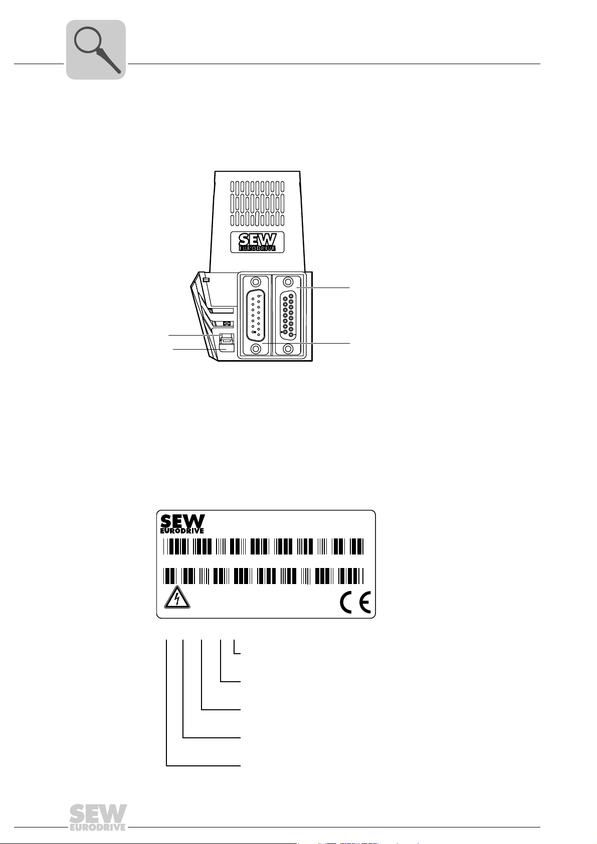
The following figure shows the MOVITRAC® LTX servo module:
[1]
[3]
[4]
[1] X14 Application connector
[2] X13 Motor feedback connector
[3] Detent nose
[4] Retaining button
2.2 Unit designation
2.2.1 Sample nameplate
[2]
3575503499
LT X- H1A
Production status
Variant
Secondary functionality H = Hiperface
8
Primary functionality X = Servo module
Indicator for the LT option module
Addendum to the Operating Instructions – MOVITRAC® LTX Servo Module
Page 9
3 Mechanical Installation
MOVITRAC
®
LTP-B
1
2
3
4
5
6
7
8
9
10
11
12
13
18
14
16
W
V
BR
EMC
VAR
+
17
15
Phone: 800.894.0412 - Fax: 888.723.4773 - Web: www.clrwtr.com - Email: info@clrwtr.com
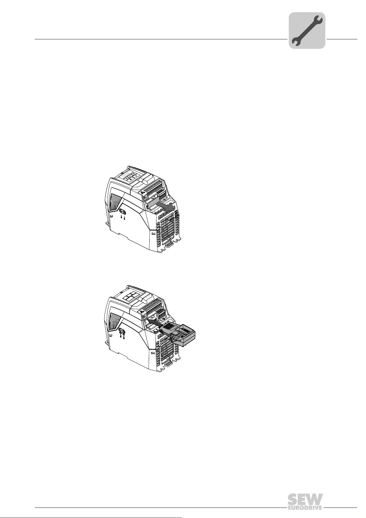
• INFORMATION
Motor cables can only be connected when the MOVITRAC
plugged because some motor connections may be covered by the LTX module.
3.1 Installing MOVITRAC® LTX
To convert MOVITRAC® LTP-B into MOVITRAC® LTX, carry out the following steps:
1. Remove the protective cover from the LTX slot.
Mechanical Installation
Installing MOVITRAC® LTX
®
LTX module is not
3
3577877003
2. Carefully insert the LTX servo module into the slot. Make sure you insert the LTX
module evenly to prevent the pins from being damaged.
3551073931
Addendum to the Operating Instructions – MOVITRAC® LTX Servo Module
9
Page 10
3
MOVITRAC
®
LTP-B
1
2
3
4
5
6
7
8
9
10
11
12
13
1
8
14
16
W
V
BR
EMC
VAR
+
17
15
[2]
[1]
Phone: 800.894.0412 - Fax: 888.723.4773 - Web: www.clrwtr.com - Email: info@clrwtr.com
Mechanical Installation
Removing MOVITRAC® LTX
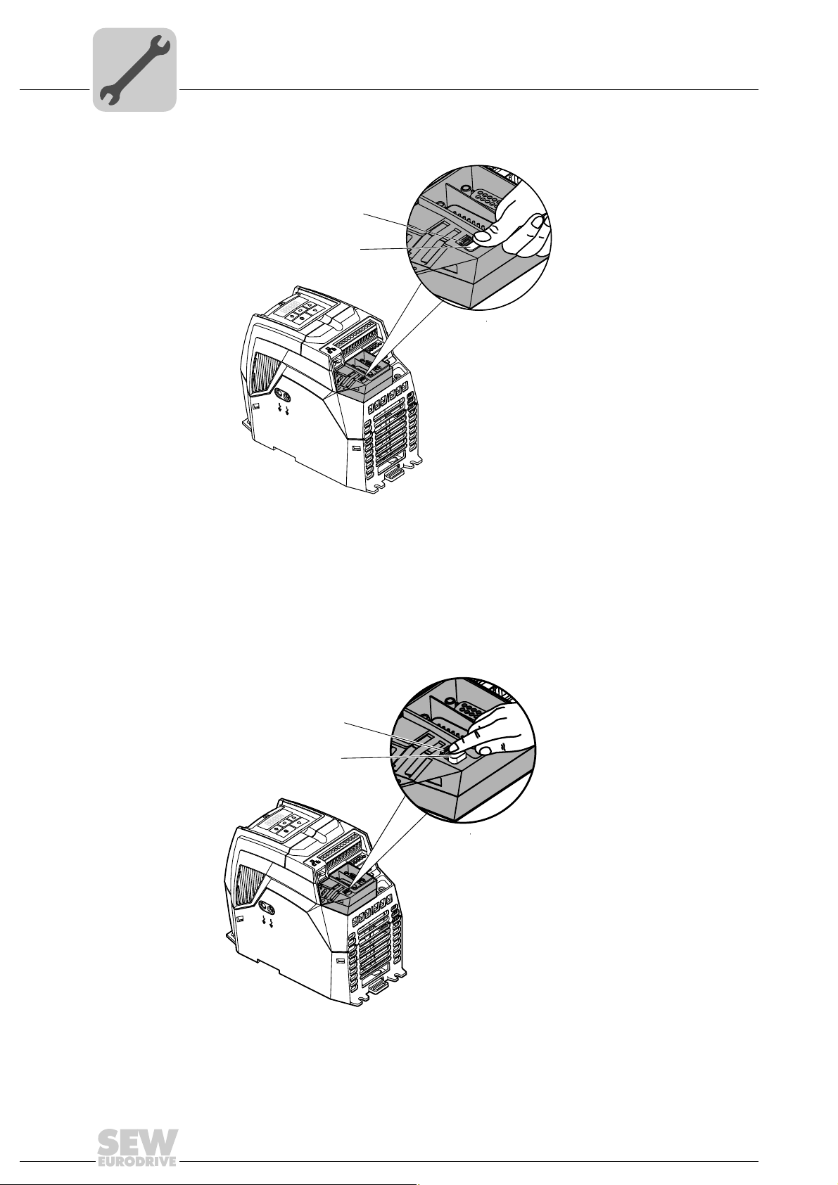
3. Secure the LTX servo module by pressing the retaining button [1].
[1] Retaining button
[2] Detent nose
3.2 Removing MOVITRAC® LTX
To unlock the LTX servo module, push the detent nose [2] in the direction of the slot to
release the retaining button [1].
[2]
[1]
LTP-B
®
MOVITRAC
EMC
VAR
8
7
6
5
4
3
2
1
3579840267
13
12
11
10
9
8
1
17
16
15
14
W
V
BR
+
10
3579838347
Addendum to the Operating Instructions – MOVITRAC® LTX Servo Module
Page 11

4 Electrical Installation
Phone: 800.894.0412 - Fax: 888.723.4773 - Web: www.clrwtr.com - Email: info@clrwtr.com
This chapter illustrates the wiring of the following connections:
• Main terminals
• Relay terminals
• Motor encoder X13
• Application connection X14
The wiring of the main terminals and the application con nection depends o n the operating mode of the drive. The drive offers the following operating modes:
• Keypad mode
• Terminal mode
• External control mode
• SEW controller mode
• Operation via gateway
Electrical Installation
4
Proper functioning requires wiring according to the respective operating mode. The
wiring options are therefore described in different sub-ch apters.
We strongly recommend to perform a simple startup first as this chapter refers to the
respective sub-chapter regarding the wiring according to the selected operating mode.
The connection X13 for the motor encoder and the r elay terminals are wired in the same
way for all operating modes. This is why the wiring is only described once for those two
connections.
Addendum to the Operating Instructions – MOVITRAC® LTX Servo Module
11
Page 12

4
Phone: 800.894.0412 - Fax: 888.723.4773 - Web: www.clrwtr.com - Email: info@clrwtr.com
Electrical Installation
Overview of signal terminals for keypad mode
4.1 Overview of signal terminals for keypad mode
4.1.1 Main terminals
IP20 and IP55
+24 V
DI 1
DI 2
DI 3
+10 V
AI 1 / DI 4
0 V
AO 1 / DO 1
0 V
AI 2 / DI 5
1 234 56789101112 13
3614563083
AO 2 / DO 2
PSE+
PSE–
The signal terminal block is equipped with the following signal connections:
Terminal
1) Do not connect any cables
Signal Function
no.
1 +24 V Output +24 V reference
2 DI1 Enable Positive logic
3DI2 n.s.
4DI3 n.s.
5 +10 V n.s.
6 AI1 / DI4 n.s.
7 0 V 0 V reference potential 0 V reference potential (Pot. supply –)
8 AO1 / DO1 n.s.
9 0 V 0 V reference potential 0 V reference potential
10 AI2 / DI5 n.s.
11 AO2 / DO2 n.s.
12 PSE + Output stage enable +24 V must be connected to PSE+
13 PSE– GND must be connected to PSE–
P1-12 =1
P1-15 =1
(pre-assigned)
voltage
1)
1)
1)
1)
1)
1)
1)
Description
Ref. for the activation of DI1 – DI3 (max. 100 mA)
"Logic 1" input voltage range: DC 8 – 30 V
"Logic 0" input voltage range: DC 0 – 2 V
Compatible with PLC requirement if 0 V is connected
to terminal 7 or 9.
10 V ref. for analog input
(Pot. supply +, 10 mA max., 1 kΩ min.)
0–10V, 0–20mA, 4–20mA
"Logic 1" input voltage range: DC 8 – 30 V
0 – 10 V, 20 mA analog
24 V, 20 mA digital
0–10V, 0–20mA, 4–20mA
"Logic 1" input voltage range: DC 8 – 30 V
0 – 10 V, 20 mA analog
24 V, 20 mA digital
12
Addendum to the Operating Instructions – MOVITRAC® LTX Servo Module
Page 13

Overview of signal terminals for keypad mode
9
15
1
8
Phone: 800.894.0412 - Fax: 888.723.4773 - Web: www.clrwtr.com - Email: info@clrwtr.com
4.1.2 Application connection assignment X14
Electrical Installation
4
Terminal
no.
Signal Function
P1-17 = 1 (pre-assigned)
1)
1
1)
2
DI11 n.s.
DI12 n.s.
2)
31)DI13 n.s.
DI14 /
1)
4
1)
5
1)
6
1)
7
1)
8
n.s.
AI11
PI1 n.s.
/PI1 n.s.
PI2 n.s.
/PI2 n.s.
9An.s.
10 /A n.s.
11 B n.s.
12 /B n.s.
13 Z n.s.
14 /Z n.s.
2)
2)
2)
2)
2)
2)
2)
2)
2)
2)
2)
2)
2)
15 0 V
1) Terminal assignment depends on parameter settings
2) Do not connect any cables
Connector type
X14
D-sub 15-pole
(male)
Addendum to the Operating Instructions – MOVITRAC® LTX Servo Module
13
Page 14
4
+24 V
DI 1
DI 2
DI 3
+10 V
AI 1 / DI 4
0 V
AO 1 / DO 1
0 V
AO 2 / DO 2
PSE+
PSE–
AI 2 / DI 5
1 234 56789101112 13
Phone: 800.894.0412 - Fax: 888.723.4773 - Web: www.clrwtr.com - Email: info@clrwtr.com
Electrical Installation
Overview of signal terminals for terminal mode (internal ramp control of the
4.2 Overview of signal terminals for terminal mode (internal ramp control of the
LTP without controller/gateway)
4.2.1 Main terminals
IP20 and IP55
3616350731
The signal terminal block is equipped with the following signal connections:
Terminal
1) Do not connect any cables
Signal Function
no.
1 +24 V Output +24 V reference
2 DI1 Enable Positive logic
3DI2 n.s.
4DI3 n.s.
5 +10 V Output +10 V reference
6 AI1 / DI4 Analog input (12 bit)
7 0 V 0 V reference potential 0 V reference potential (Pot. supply –)
8 AO1 / DO1 n.s.
9 0 V 0 V reference potential 0 V reference potential
10 AI2 / DI5 n.s.
11 AO2 / DO2 n.s.
12 PSE + Output stage enable +24 V must be connected to PSE+
13 PSE– GND must be connected to PSE–
P1-12 =0
P1-15 =1
(pre-assigned)
voltage
1)
1)
voltage
reference speed
1)
1)
1)
Description
Ref. for the activation of DI1 – DI3 (max. 100 mA)
"Logic 1" input voltage range: DC 8 – 30 V
"Logic 0" input voltage range: DC 0 – 2 V
Compatible with PLC requirement if 0 V is connected
to terminal 7 or 9.
10 V ref. for analog input
(Pot. supply +, 10 mA max., 1 kΩ min.)
0–10V, 0–20mA, 4–20mA
"Logic 1" input voltage range: DC 8 – 30 V
0 – 10 V, 20 mA analog
24 V, 20 mA digital
0–10V, 0–20mA, 4–20mA
"Logic 1" input voltage range: DC 8 – 30 V
0 – 10 V, 20 mA analog
24 V, 20 mA digital
14
Addendum to the Operating Instructions – MOVITRAC® LTX Servo Module
Page 15

Electrical Installation
Phone: 800.894.0412 - Fax: 888.723.4773 - Web: www.clrwtr.com - Email: info@clrwtr.com
Overview of signal terminals for terminal mode (internal ramp control of the
4.2.2 Application connection assignment X14
4
15
Terminal
no.
9
1
8
Signal Function
P1-17 = 1 (pre-assigned)
1)
1
1)
2
DI11 n.s.
DI12 n.s.
2)
31)DI13 n.s.
DI14 /
1)
4
1)
5
1)
6
1)
7
1)
8
n.s.
AI11
PI1 n.s.
/PI1 n.s.
PI2 n.s.
/PI2 n.s.
9An.s.
10 /A n.s.
11 B n.s.
12 /B n.s.
13 Z n.s.
14 /Z n.s.
2)
2)
2)
2)
2)
2)
2)
2)
2)
2)
2)
2)
2)
15 0 V
1) Terminal assignment depends on parameter settings
2) Do not connect any cables
Connector type
X14
D-sub 15-pole
(male)
Addendum to the Operating Instructions – MOVITRAC® LTX Servo Module
15
Page 16

4
+24 V
DI 1
DI 2
DI 3
+10 V
AI 1 / DI 4
0 V
AO 1 / DO 1
0 V
AO 2 / DO 2
PSE+
PSE–
AI 2 / DI 5
1 234 56789101112 13
Phone: 800.894.0412 - Fax: 888.723.4773 - Web: www.clrwtr.com - Email: info@clrwtr.com
Electrical Installation
Overview of signal terminals for third-party controllers
4.3 Overview of signal terminals for third-party controllers
4.3.1 Main terminals
IP20 and IP55
3614563083
The signal terminal block is equipped with the following signal connections:
Terminal
1) Do not connect any cables
Signal Function
no.
1 +24 V Output +24 V reference
2 DI1 Enable Positive logic
3DI2 n.s.
4DI3 n.s.
5 +10 V n.s.
6 AI1 / DI4 n.s.
7 0 V 0 V reference potential 0 V reference potential (Pot. supply –)
8 AO1 / DO1 n.s.
9 0 V 0 V reference potential 0 V reference potential
10 AI2 / DI5 n.s.
11 AO2 / DO2 n.s.
12 PSE + Output stage enable +24 V must be connected to PSE+
13 PSE– GND must be connected to PSE–
P1-12 =0
P1-15 =1
(pre-assigned)
voltage
1)
1)
1)
1)
1)
1)
1)
Description
Ref. for the activation of DI1 – DI3 (max. 100 mA)
"Logic 1" input voltage range: DC 8 – 30 V
"Logic 0" input voltage range: DC 0 – 2 V
Compatible with PLC requirement if 0 V is connected
to terminal 7 or 9.
10 V ref. for analog input
(Pot. supply +, 10 mA max., 1 kΩ min.)
0–10V, 0–20mA, 4–20mA
"Logic 1" input voltage range: DC 8 – 30 V
0 – 10 V, 20 mA analog
24 V, 20 mA digital
0–10V, 0–20mA, 4–20mA
"Logic 1" input voltage range: DC 8 – 30 V
0 – 10 V, 20 mA analog
24 V, 20 mA digital
16
Addendum to the Operating Instructions – MOVITRAC® LTX Servo Module
Page 17
Overview of signal terminals for third-party controllers
9
15
1
8
9
15
1
8
Phone: 800.894.0412 - Fax: 888.723.4773 - Web: www.clrwtr.com - Email: info@clrwtr.com
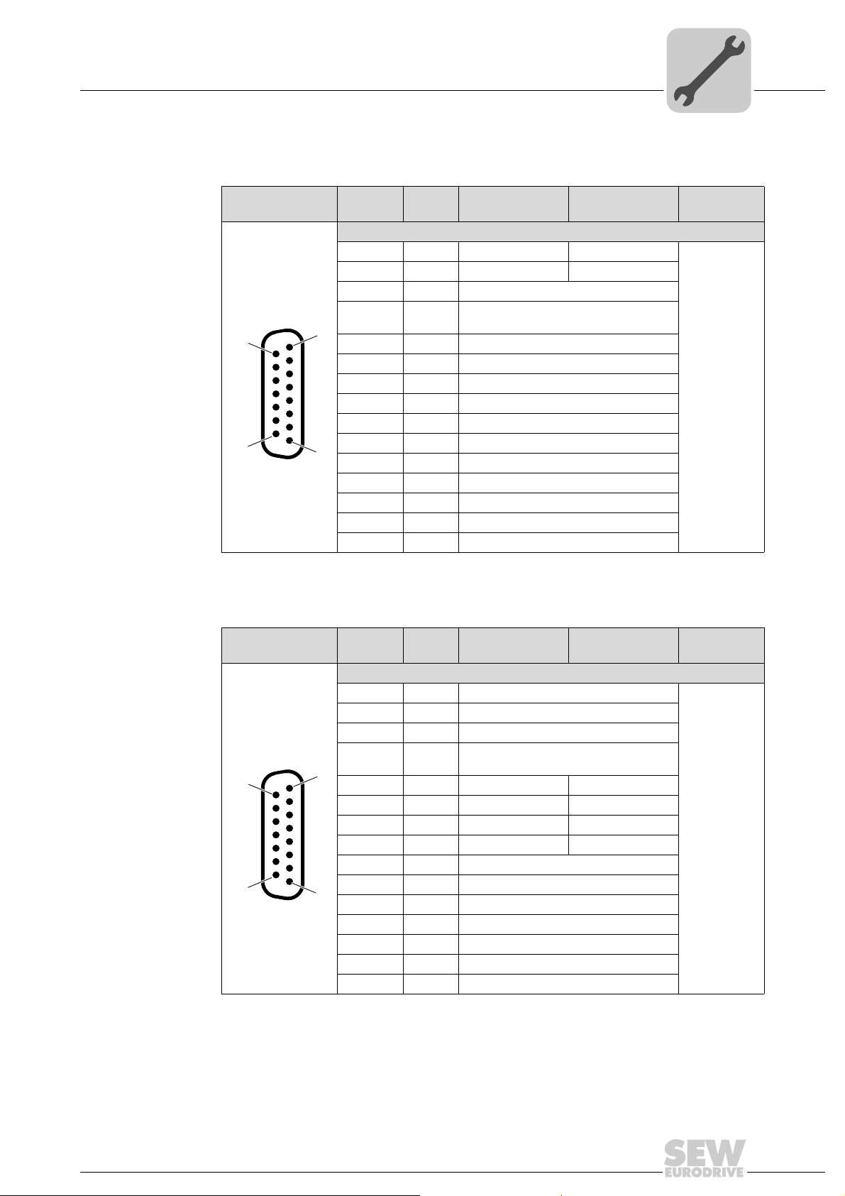
4.3.2 Application connection assignment X14
±10 V reference
potential and
encoder simulation
1) Terminal assignment depends on parameter settings
Terminal
no.
1
2
3
4
5
6
7
8
10 /A Encoder simulation output /A
11 B Encoder simulation output B
12 /B Encoder simulation output /B
13 Z Encoder simulation Z
14 /Z Encoder simulation /Z
15 0 V
Electrical Installation
Signal Function
P1-17 =5
1)
DI11 – Limit switch left
1)
DI12 – Limit switch right
1)
DI13 Fast reference cam for referencing input
DI14 /
1)
AI11
1)
1)
/PI1 –
1)
1)
/PI2 –
9 A Encoder simulation output A
Fast + – 10 V reference speed signal
input
PI1 –
PI2 –
Function
P1-17 =6
X14
4
Connector
type
D-sub 15-pole
(male)
Interface pulse /
direction or A/B
phase
1) Terminal assignment depends on parameter settings. Input is RS422-compliant and not HTL-capable
(connection of 24 V signals not possible). Maximum voltage of –10 to 15 V between PI1, /PI1, PI2, /PI2
and 0 V. Nominal operation level DC ± 6 V differential and min. DC ± 2 V differential.
2) Do not connect any cables
Terminal Signal Function
P1-17 =5
1)
1
DI11 –
1)
DI12 –
2
1)
3
DI13 –
DI14 /
1)
4
AI11
1)
5
1)
6
/PI1 Input \pulse Input \A phase
1)
7
1)
/PI2 Input \direction Input \B phase
8
9An.s.
10 /A n.s.
11 B n.s.
12 /B n.s.
13 Z n.s.
14 /Z n.s.
15 0 V
–
PI1 Input pulse Input A phase
PI2 Input direction Input B phase
2)
2)
2)
2)
2)
2)
X14
Function
P1-17 =6
Connector
type
D-sub 15-pole
(male)
Addendum to the Operating Instructions – MOVITRAC® LTX Servo Module
17
Page 18
4
A
[1]
B
[1]
t1t
2
– 2.5 V
– 2.5 V
+ 2.5 V
+ 2.5 V
≥ 2.5 μs ≥ 2.5 μs
A
[1]
B
[1]
– 2.5 V
– 2.5 V
+ 2.5 V
+ 2.5 V
≥ 2.5 μs ≥ 2.5 μs
t1t
2
≥ 2.5μs ≥ 2.5 μs
Pulse
[2]
t
v
" low "
– 2.5 V
+ 2.5 V
+ 2.5 V
– 2.5 V
+ 2.5 V
Direction
[2]
t
ON
PULSE
[2]
≥ 2.5 μs ≥ 2.5 μs
t
v
– 2.5 V
+ 2.5 V
– 2.5 V
t
ON
Direction
[2]
+ 2.5 V
" high "
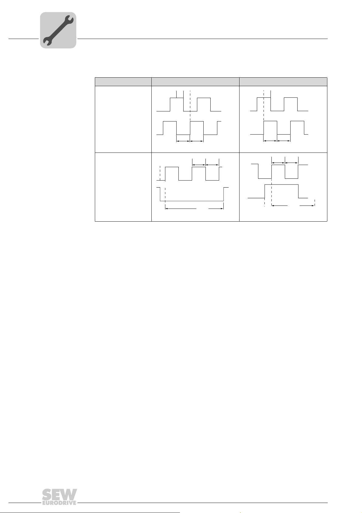
Phone: 800.894.0412 - Fax: 888.723.4773 - Web: www.clrwtr.com - Email: info@clrwtr.com
Electrical Installation
Overview of signal terminals for third-party controllers
The following illustration shows the motor behavior according to the setting of parameter
P1-17 and the signal sequence.
P1-17 Negative direction (CCW) Positive direction (CW)
Input A/B phase
P1-17 =8
Input pulse/direction
P1-17 =7
[1] The displayed signals A or B are the resulting signals/voltage values between A (PI1) and /A (/PI1)
or B (PI2) and /B (/PI2).
[2] The displayed signals pulse and direction are the resulting signals/voltage values between pulse
(PI1) and /pulse (/PI1) or direction (PI2) and /direction (/PI2).
t
, t2t1/t2 ≥ 1.25 ±10 %
1
tv ≥ 0.5 µs
t
v
t
ONtON
≥ 100 µs
18
Addendum to the Operating Instructions – MOVITRAC® LTX Servo Module
Page 19

Electrical Installation
+24 V
DI 1
DI 2
DI 3
+10 V
AI 1 / DI 4
0 V
AO 1 / DO 1
0 V
AO 2 / DO 2
PSE+
PSE–
AI 2 / DI 5
1 234 56789101112 13
+24 V
DI 1
DI 2
DI 3
+10 V
AI 1 / DI 4
0 V
AO 1 / DO 1
0 V
AO 2 / DO 2
PSE+
PSE–
AI 2 / DI 5
1 234 56789101112 13
Phone: 800.894.0412 - Fax: 888.723.4773 - Web: www.clrwtr.com - Email: info@clrwtr.com
Overview of signal terminals for SEW controllers
4.4 Overview of signal terminals for SEW controllers
4.4.1 Main terminals
IP20 and IP55 profile 1 IP55 and IP66 profile 2
3616834059 3616835979
4
The signal terminal block is equipped with the following signal connections:
Terminal no.
1) Do not connect any cables
Signal Function
Profile 1
P1-12 = set automatically
P1-15 = set automatically
1 +24 V Output +24 V ref-
2 DI1 Start Start Positive logic
3DI2 Reset Reset
4 DI3 Reference cam Reference cam
5 +10 V n.s.
6 AI1 / DI4 n.s.
7 0 V 0 V reference
8 AO1 / DO1 n.s.
9 0 V 0 V reference
10 AI2 / DI5 n.s.
11 AO2 / DO2 n.s.
12 PSE + Output stage
13 PSE– GND must be connected to PSE–
erence voltage
1)
1)
potential
1)
potential
1)
1)
enable
Function
Profile 2
Output +24 V
reference voltage
1)
n.s.
Limit switch + 0–10V, 0–20mA, 4–20mA
0 V reference
potential
1)
n.s.
0 V reference
potential
Limit switch – 0–10V, 0–20mA, 4–20mA
1)
n.s.
Output stage
enable
Description
Ref. for the activation of DI1 – DI3
(max. 100 mA)
"Logic 1" input voltage range:
DC 8 – 30 V
"Logic 0" input voltage range:
DC 0 – 2 V
Compatible with PLC requirement if 0
V is connected to terminal 7 or 9.
10 V ref. for analog input
(Pot. supply +, 10 mA max., 1 kΩ
min.)
"Logic 1" input voltage range:
DC 8 – 30 V
0 V reference potential (Pot. supply –)
0 – 10 V, 20 mA analog
24 V, 20 mA digital
0 V reference potential
"Logic 1" input voltage range:
DC 8 – 30 V
0 – 10 V, 20 mA analog
24 V, 20 mA digital
+24 V must be connected to PSE+
Addendum to the Operating Instructions – MOVITRAC® LTX Servo Module
19
Page 20

4
9
15
1
8
Phone: 800.894.0412 - Fax: 888.723.4773 - Web: www.clrwtr.com - Email: info@clrwtr.com
Electrical Installation
Overview of signal terminals for SEW controllers
4.4.2 Application connection assignment X14
Terminal
no.
Signal Function
P1-17 = 1 (pre-assigned)
1)
1
DI11 n.s.
1)
DI12 n.s.
2
1)
3
DI13 Touch probe 1
DI14 /
1)
4
AI11
1)
PI1 n.s.
5
1)
6
/PI1 n.s.
1)
7
PI2 n.s.
1)
8
/PI2 n.s.
9An.s.
10 /A n.s.
11 B n.s.
12 /B n.s.
13 Z n.s.
14 /Z n.s.
2)
2)
Touch probe 2
2)
2)
2)
2)
2)
2)
2)
2)
2)
2)
15 0 V
1) Terminal assignment depends on parameter settings
2) Do not connect any cables
Connector
type
X14
D-sub 15-pole
(male)
20
Addendum to the Operating Instructions – MOVITRAC® LTX Servo Module
Page 21

Electrical Installation
Phone: 800.894.0412 - Fax: 888.723.4773 - Web: www.clrwtr.com - Email: info@clrwtr.com
Overview of signal terminals for SEW gateways
4.5 Overview of signal terminals for SEW gateways
4.5.1 Main terminals
IP20 and IP55
+24 V
DI 1
DI 2
DI 3
+10 V
AI 1 / DI 4
0 V
AO 1 / DO 1
0 V
AO 2 / DO 2
PSE+
AI 2 / DI 5
1 234 56789101112 13
PSE–
3614563083
4
The signal terminal block is equipped with the following signal connections:
Terminal no.
1) Do not connect any cables
Signal Function
P1-12 =0
P1-15 =1
(pre-assigned)
1 +24 V Output +24 V reference
2 DI1 Enable Positive logic
3DI2 n.s.
4DI3 n.s.
5 +10 V n.s.
6 AI1 / DI4 n.s.
7 0 V 0 V reference potential 0 V reference potential (Pot. supply –)
8 AO1 / DO1 n.s.
9 0 V 0 V reference potential 0 V reference potential
10 AI2 / DI5 n.s.
11 AO2 / DO2 n.s.
12 PSE + Output stage enable +24 V must be connected to PSE+
13 PSE– GND must be connected to PSE–
voltage
1)
1)
1)
1)
1)
1)
1)
Description
Ref. for the activation of DI1 – DI3 (max. 100 mA)
"Logic 1" input voltage range: DC 8 – 30 V
"Logic 0" input voltage range: DC 0 – 2 V
Compatible with PLC requirement if 0 V is connected
to terminal 7 or 9.
10 V ref. for analog input
(Pot. supply +, 10 mA max., 1 kΩ min.)
0–10V, 0–20mA, 4–20mA
"Logic 1" input voltage range: DC 8 – 30 V
0 – 10 V, 20 mA analog
24 V, 20 mA digital
0–10V, 0–20mA, 4–20mA
"Logic 1" input voltage range: DC 8 – 30 V
0 – 10 V, 20 mA analog
24 V, 20 mA digital
Addendum to the Operating Instructions – MOVITRAC® LTX Servo Module
21
Page 22

4
9
15
1
8
Phone: 800.894.0412 - Fax: 888.723.4773 - Web: www.clrwtr.com - Email: info@clrwtr.com
Electrical Installation
Overview of signal terminals for SEW gateways
4.5.2 Application connection assignment X14
Terminal
Signal Function Connector
no.
1)
1
DI11 n.s.
1)
DI12 n.s.
2
1)
3
DI13 n.s.
DI14 /
1)
4
AI11
1)
5
PI1 n.s.
1)
6
/PI1 n.s.
1)
7
PI2 n.s.
1)
8
/PI2 n.s.
9An.s.
10 /A n.s.
11 B n.s.
12 /B n.s.
13 Z n.s.
14 /Z n.s.
n.s.
2)
2)
2)
2)
2)
2)
2)
2)
2)
2)
2)
2)
2)
2)
15 0 V
1) Terminal assignment depends on parameter settings
2) Do not connect any cables
type
X14
D-sub 15-pole
(male)
22
Addendum to the Operating Instructions – MOVITRAC® LTX Servo Module
Page 23

Overview of relay terminals and X13
9
15
1
8
Phone: 800.894.0412 - Fax: 888.723.4773 - Web: www.clrwtr.com - Email: info@clrwtr.com
4.6 Overview of relay terminals and X13
4.6.1 Relay terminal overview for all operating modes
Relay output 1
14 15 16 17 18
Electrical Installation
Reference potential
Relay output 1 NO
Relay output 2
Reference potential
Relay output 1 NC
Relay output 2 NO
4
3003612555
Terminal
no.
14 Relay output 1 reference Relay contact (AC 250 V / DC 30 V @ 5 A)
15 Relay output 1 NO
16 Relay output 1 NC
17 Relay output 2 reference
18 Relay output 2 NO
Signal Description
4.6.2 Connection assignment X13 motor encoder for all operating modes
Terminal
no.
1 Signal track A (cos+)
2 Signal track B (sin+)
1)
3n.s.
4DATA+
5 n.s.
6KTY–
1)
7 n.s.
8DGND
9 Signal track A_N (cos–)
10 Signal track B_N (sin–)
11 n.s.
12 DATA–
13 n.s.
14 KTY +
15 Us
1) Do not connect any cables
1)
Function Connector type
X13
D-sub 15-pole
(female)
Addendum to the Operating Instructions – MOVITRAC® LTX Servo Module
23
Page 24

5
00
I
Phone: 800.894.0412 - Fax: 888.723.4773 - Web: www.clrwtr.com - Email: info@clrwtr.com
5Startup
5.1 User interface
5.1.1 Keypad
Startup
User interface
®
Each MOVITRAC
ating and setting-up the drive without any further devices.
The keypad has 5 keys with the following functions:
LTP-B is equipped with a keypad as standard that allows for oper-
Start (execute)
Stop/reset • Stops the motor
Navigate • Shows real-time information
Up • Increases the speed in real-time mode
Down • Decreases the speed in real-time mode
• Enables the motor
• Reverses the direction of rotation if bidirectional keypad mode is activated
• Acknowledges an error
• Press and hold to enable/disable parameter edit mode
• Saves parameter changes
• Increases the parameter values in parameter edit mode
• Decreases the parameter values in parameter edit mode
If the parameters are set to the factory settings, the "Start" and "Stop" keys of the keypad
are disabled. In order to enable the "Start" and "Stop" keys of the keypad, P1-12 must
be set to 1 or 2, see operating instructions for MOVITRAC
®
LTP-B, chapter "Parameter
group 1: Standard parameters".
The parameter edit menu can only be accessed via the "Navigate" key. Press and hold
the key (> 1 s) to switch between the parameter edit menu and th e real-time display (operating state of the drive/speed). Press this key briefly (< 1 s) to switch between the operating speed and operating current of the running drive.
[1]
LT
®
[4]
[2]
MOVITRAC
[5]
[3]
[1] Display [4] Navigate
[2] Start [5] Up
[3] Stop/reset [6] Down
[6]
2933664395
• NOTE
To restore the factory settings, pr ess th e "Up" , "Do wn" an d "Stop/ rese t" keys s imul-
taneously for > 2 s. "P-deF" is displayed.
Press the "Stop/reset" key again to confirm the change and to reset the inverter.
24
Addendum to the Operating Instructions – MOVITRAC® LTX Servo Module
Page 25

Extended key combinations
Phone: 800.894.0412 - Fax: 888.723.4773 - Web: www.clrwtr.com - Email: info@clrwtr.com
Startup
User interface
I
5
00
Function The device dis-
Quick parameter
group selection
Selection of the
lowest group
parameter
Set the parameter
to the lowest value
Changing individual
digits of a parameter value
1) Parameter group access must be activated by setting P1-14 to "101".
plays...
Px-xx "Navigate" + "Up" keys The next higher parame-
1)
Px-xx "Navigate" + "Down"
Px-xx "Up" + "Down" keys The first parameter of
Numerical value
(when changing a
parameter value)
Numerical value
(when changing a
parameter value)
Press... Result Example
keys
"Up" + "Down" keys The parameter is set to
"Stop/reset" + "Navigate" keys
ter group is selected
The next lower parameter group is selected
a
group is selected
the lowest value
The individual parameter digits can be changed
• "P1-10" is displayed
• Press the "Navigate" + "Up"
keys
• Now, "P2-01" is displayed
• "P2-26" is displayed
• Press the "Navigate" + "Down"
keys
• Now, "P1-01" is displayed
• "P1-10" is displayed
• Press the "Up" + "Down" keys
• Now, "P1-01" is displayed
When changing P1-01:
• "50.0" is displayed
• Press the "Up" + "Down" keys
• Now "0.0" is displayed
When setting P1-10:
• "0" is displayed
• Press the "Stop/reset" + "Navigate" keys
• Now "_0" is displayed
• Press the "Up" key
• Now "10" is displayed
• Press the "Stop/reset" + "Navigate" keys
• Now "_10" is displayed
• Press the "Up" key
• Now "110" is displayed
etc.
5.1.2 Display
A six-digit 7-segment display is integrated in each drive. It can be used to monitor drive
functions and set parameters.
Addendum to the Operating Instructions – MOVITRAC® LTX Servo Module
25
Page 26

5
00
I
Phone: 800.894.0412 - Fax: 888.723.4773 - Web: www.clrwtr.com - Email: info@clrwtr.com
Startup
Simple startup of MOVITRAC® LTX
5.2 Simple startup of MOVITRAC® LTX
The following figure shows the MOVITRAC® LTP-B without and with inserted LTX servo
module.
[1]
L1/L L2/N L3
L1/L L2/N L3
[2]
[3]
[4]
LTP-B
®
MOVITRAC
LTP-B
®
MOVITRAC
[5]
[6]
+
BR U V W
+
BR U V W
[8]
[7]
[9]
[11]
[10]
[1] Supply system terminals [8] Detent
[2] Quick aid [9] Push button
[3] Display [10] X14 application connection
[4] Keypad [11] X13 Motor encoder connection
[5] Main terminals
[6] Relay terminals
[7] Connection for motor and brake chopper
26
Addendum to the Operating Instructions – MOVITRAC® LTX Servo Module
Page 27

Simple startup of MOVITRAC® LTX
CMP
Motor
PE U V W
123
4
131415
BMV
DC 24 V
K11
(AC-3)
D
–
+
C
14 15 16 17 18
+
––
+
[6]
[7]
[12]
(1)
(2)
00
I
Phone: 800.894.0412 - Fax: 888.723.4773 - Web: www.clrwtr.com - Email: info@clrwtr.com
5.2.1 Basic wiring and settings prior to operating mode-specific startup
• Connect the CMP motor with a pre-fabricated SEW motor cable to the motor connection terminals [7].
• If you want to connect a CMP brak emotor, use a pre-fabricated SEW brakemotor
cable and a BMV brake rectifier. The brake must be wired according to the following
wiring diagram.
Startup
5
3783241355
[6] Relay terminals
[7] Connection for motor and brake chopper
[12] Optionally integrated motor brake
• Connect the motor encoder to the motor encoder connection X13 [11] of the LTX
device with a pre-fabricated SEW encoder cable.
• WARNING Danger due to unintended restart.
The motor might restart when the inverter is connected to the supply.
– Regardless of the selected operating mode, the contacts 12 and 13 of the main
terminals [5] must be interrupted.
• Connect the inverter to the supply system by wiring the supply terminals [1].
• Turn on the inverter.
• Restore the factory settings of the inverter, if required (press the "Stop", "Up" and
"Down" keys for 5 s until "P-Def" is displayed). Confirm with the "Stop" key.
• Check whether the correct CMP motor is displayed in the parameter P1-16.
• If P1-16 = "in-syn", or if there is no access, the motor encoder does not have a valid
electronic nameplate. Without valid electronic nameplate, the motor type must be set
manually.
Setting the motor type manually:
•Set P1-14 to "1" for free access to parameters P1-16 to P1-22
•Set P1-16 to the connected motor type.
•Set P1-18 to "1" to activate the thermal motor protection KTY.
Addendum to the Operating Instructions – MOVITRAC® LTX Servo Module
• INFORMATION
Only motors of the Smart Servo Package are supported.
27
Page 28

5
P
J
J
ext
mot
122−=
00
I
Phone: 800.894.0412 - Fax: 888.723.4773 - Web: www.clrwtr.com - Email: info@clrwtr.com
Startup
Simple startup of MOVITRAC® LTX
• Once the correct motor has been set, either automatically or manually, the motor
startup is completed.
• The motor overload protection is set to "250%" to provide a high overload torque.
• If you use an SEW encoder cable, the KTY thermistor is connected by default in o rder
to provide for thermal motor protection.
• Contacts 12 and 13 of the main termin als [5] are wired according to the selected
operating mode. Now you can enable the drive. For information on the electrical
installation depending on the respective operating mode refer to chapter "Electrical
Installation" (page 11) or to the following chapters that illustrate the correct wiring
according to the operating mode.
– "Keypad mode (P1-12 = 1 or 2)" (page 29)
– "Terminal mode (basic setting) P1-12 = 0 fur LTP-internal ramp control" (page 29)
– "Linking and startup with different controllers (third-party controller and SEW
controller)" (page 30)
• WARNING Danger of electric shock.
Improper wiring my cause danger due high voltages when the motor or the drive is
enabled.
– Check the wiring according to:
• the selected operating mode
• the installation and wiring notes in chapter "Electrical Installation"
• the installation and wiring notes in chapter "Electrical Installation" in the
"MOVITRAC
®
LTP-B" operating modes.
• INFORMATION
All motors of the Smart Servo Package can be operated with standard parameter
settings of the inverter for speed and position control. You can change parameter P1-
22 for initial simple control loop optimization. Parameter P1-22 represents the
relation between total inertia (J
ext
= J
Load
+ J
Gear unit
) and motor inertia (J
mot
/ Jb
For further optimization options regar ding speed and position control, refer to chapter
"Control loop optimization in different operating modes" (page 38).
For further information regarding the motor iner tia, refer to chapter "Ma ss moment of
inertia of the CMP motors in the Smart Servo Package" (page 56).
mot
).
28
Addendum to the Operating Instructions – MOVITRAC® LTX Servo Module
Page 29

5.2.2 Keypad mode (P1-12 = 1 or 2)
00
I
Phone: 800.894.0412 - Fax: 888.723.4773 - Web: www.clrwtr.com - Email: info@clrwtr.com
For operation in keypad mode:
• As the electrical installation depends on the respective operating mode, chapter
"Overview of signal terminals for keypad mode" (page 12) provides wiring information.
•Set P1-12 to "1" (uni-directional) or "2" (bi-directional).
• Connect a wire break or a switch between terminal 1 and 2 to the user term inal block
in order to enable the drive.
• Press the "Start" key. The drive is enabled with 0.0 Hz.
• Press the "Up" key to increase the speed or the "Down" key to decrease the speed.
• To stop the drive, press the "Stop/reset" key.
• Press the "Start" key again to resume the original speed.
If bi-directional mode is enabled (P1-12 = 2), the direction is reversed by pressing the
"Start" key.
Startup
Simple startup of MOVITRAC® LTX
5
• INFORMATION
The required target speed can be set by pressing the "Stop/reset" key in standstill.
By then pressing the "Start" key, the drive moves along a ramp until it has reached
this speed.
5.2.3 Terminal mode (basic setting) P1-12 = 0 fur LTP-internal ramp control
For operation in keypad mode (basic setting):
• As the electrical installation depends on the respective operating mode, chapter
"Overview of signal terminals for termin al mode " (page 14) provides wiring information.
• P1-12 must be set to "0" (basic setting).
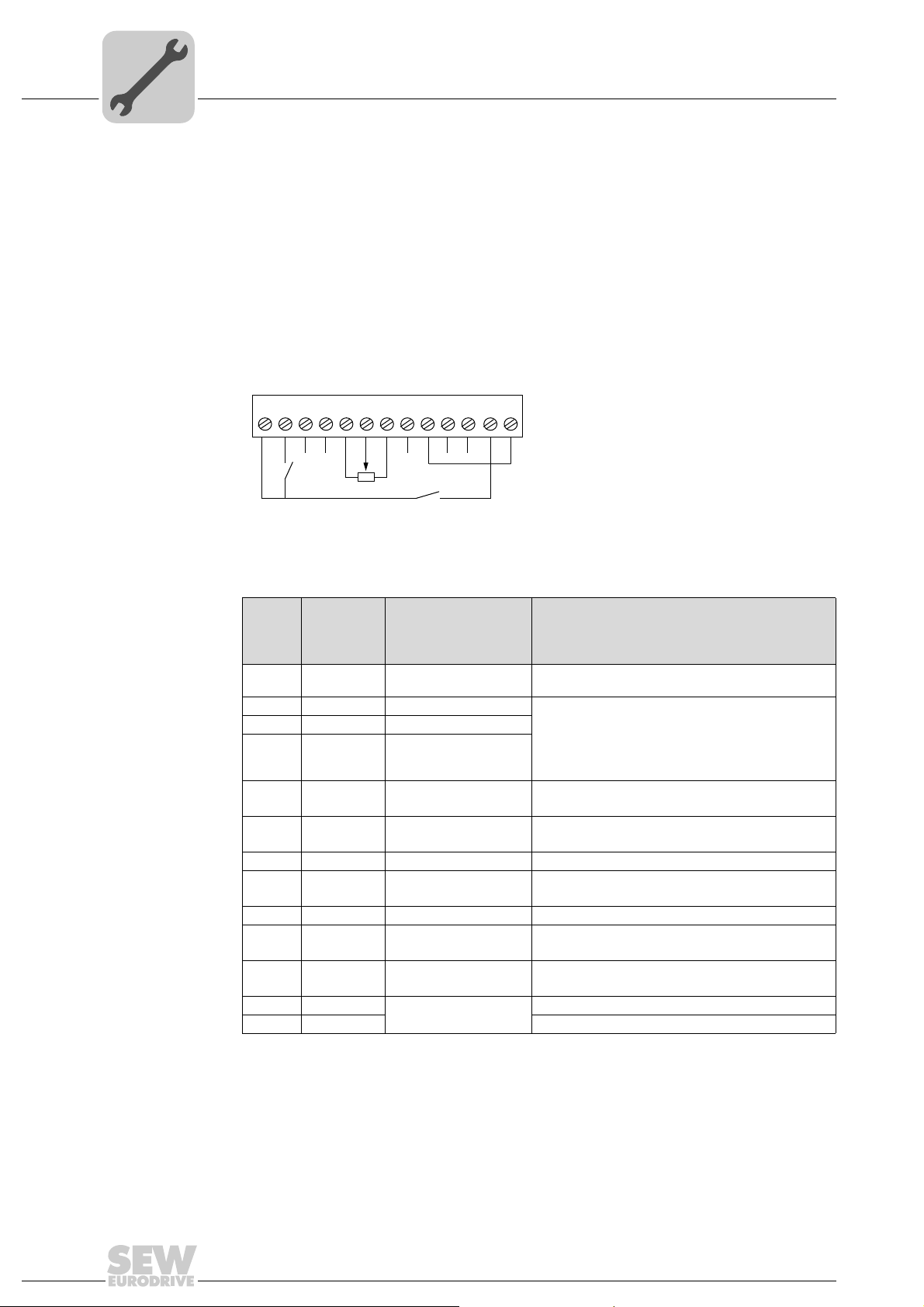
• Connect a switch between terminals 1 and 2 on the user terminal block.
• Connect a potentiometer (1 – 10 k) between terminals 5, 6 and 7, the slidin g co ntact
is connected to pin 6.
• Provide for a connection between terminals 1 and 2 in order to enable the drive.
• Set the speed using the potentiometer.
Addendum to the Operating Instructions – MOVITRAC® LTX Servo Module
29
Page 30

5
startup modes
startup tools
External control mode
Keypad
Manually
Pulse/direction; ± 10V
w. encoder simulation
Velocity control
CCU
configurable control unit
User-programmable
MS
(PLCEditor)
e.g. bus positioning
Gateway
(DFP-UOH...)
MOVI-PLC®
Motion and logic controller
Keypad
MS
(Drive Startup)
Keypad
MS
(Gateway Configurator)
SEW gateway modeSEW controller mode
Keypad
SD card
MS
(Drive Startup)
00
I
Phone: 800.894.0412 - Fax: 888.723.4773 - Web: www.clrwtr.com - Email: info@clrwtr.com
Startup
Simple startup of MOVITRAC® LTX
5.2.4 Linking and startup with different controllers (third-party controller and SEW controller)
Third-party
controller mode
9007202885779467
Third-party controllers, SEW controllers and gateway operation are described in the
following chapters.
For operation in third-party controller mode:
Setting motor limits (applies to all third-party controller modes):
• Set parameter P1-01 to the upper limit of the required motor spe ed (N
[rpm]). If
max
the values are displayed in Hz, set the rated speed of the motor in P1-10 to the r ated
speed of the connected motor. P1-01 also represents the possible ma xim u m sp ee d
in analog mode with ± 10 V, if DC 10 V are connected. (For all Smart Servo Package
motors, P1-10 should show 4500 rpm). For a detailed description of this parameter,
refer to the MOVITRAC
•Set P1-03 to the required acceleration ramp that specifies the time in seconds, the
®
LTP-B operating instructions.
output frequency increases from 0 to 50 Hz (AccRamp [s]). The 6-pole CMP motors
of the Smart Servo Package require an output frequency of 150 Hz for a speed of
3000 rpm, for example. You ha ve to set P1-03 to 0.33 s to specify an acceleration
ramp of 3000 rpm/s. For a detailed description of this parameter, refer to the
®
MOVITRAC
•Set P1-04 to the required deceleration/stop ramp that specifies the time in seconds,
the output frequency decreases from 50 to 0 Hz (DecRamp [s]). Proceed as with P1-
LTP-B operating instructions.
03.
30
Addendum to the Operating Instructions – MOVITRAC® LTX Servo Module
Page 31

Startup
00
I
Phone: 800.894.0412 - Fax: 888.723.4773 - Web: www.clrwtr.com - Email: info@clrwtr.com
Simple startup of MOVITRAC® LTX
Operation with ±10 V interface with analog input on the main terminal strip
(sampling cycle = 16 ms)
•Set P1-14 to 201 to access the parameters of the LTX-specific parameter group 8.
•Set P1-15 to one of the possible operating modes: 22, 23, 24 or 25.
For a detailed description of this parameter, refer to chapter "1- 15 function selection
digital inputs, LTX-specific parameters" (page 44). You can use an analog setpoint
for velocity specification at the first analog input of the main terminal strip.
•Set P1-12 to 0 (terminal control, default setting).
• If using the analog input, set P2-30 to –10 to +10 V for bipolar voltage input at the
analog input. For a detailed description of this parameter, refer to the MOVITRAC
LTP-B operating instructions.
• Use parameter P8-01 to set the scaling factor for the incremen tal encoder simulation.
For a detailed description of this parameter, refer to chapter "P8-01 simulated
encoder scaling" (page 49)
• CAUTION unexpected drive response possible.
Risk of crushing
5
®
If functions (e.g. the analog input) are set in parameter P1-15 and activated in
parameter P1-17, the input on the X14 connector has priority and the signal assignments on parameter P1-15 are overwritten or deactivated.
The wrong use of parameters P1-15 and P1-17 in conjunction with the inputs of the
terminals of X14 can cause uncontrolled movements or malfunctions of the drive.
The required electric installation of the signal terminals depends on the selected
operating mode. A wiring that does not suit the respective operating mode, can
cause uncontrolled movements or malfunctions of the drive.
– Wire the signal terminals according to chapter "Overview of signal terminals for
third-party controllers" (page 16) and/or check the existing wiring accordingly.
– Perform the parameterization of P1-15 and P1-17 according to the operating
mode.
Addendum to the Operating Instructions – MOVITRAC® LTX Servo Module
31
Page 32

5
00
I
Phone: 800.894.0412 - Fax: 888.723.4773 - Web: www.clrwtr.com - Email: info@clrwtr.com
Startup
Simple startup of MOVITRAC® LTX
Operation with ±10 V interface with fast analog input on the LTX servo module
(sampling cycle = 4 ms)
You should use the servo module inputs predominantly if you require reference cams or
a fast analog input or a stepper motor control. This will also enable the pulse/direction
control or the encoder input function.
•Set P1-14 to 201 to access the parameters of the LTX-specific parameter group 8.
•Set P1-15 to one of the possible operating modes: 22, 23, 24 or 25.
For a detailed description of this parameter, refer to chapter "1- 15 function selection
digital inputs, LTX-specific parameters" (page 44).
•Set P1-12 to 0 (terminal control, default setting).
•Set P1-17 to one of the possible operating modes: 5 or 6.
For a detailed description of the parameter, refer to chapter "P1-17 Smart Servo
operation" (page 47).
• If using the analog input, set P2-30 to –10 to +10 V for bipolar voltage input at the
analog input.
®
For a detailed description of this parameter, refer to the MOVITRAC
ing instructions.
LTP-B operat-
• Use parameter P8-01 to set the scaling factor for the encoder simulation.
For a detailed description of this parameter, refer to chapter "P8-01 simulated
encoder scaling" (page 49)
• CAUTION unexpected drive response possible.
Risk of crushing
If functions (e.g. the analog input) are set in parameter P1-15 and activated in
parameter P1-17, the input on the X14 connector has priority and the signal assignments on parameter P1-15 are overwritten or deactivated.
The wrong use of parameters P1-15 and P1-17 in conjunction with the inputs of the
terminals of X14 can cause uncontrolled movements or malfunctions of the drive.
The required electric installation of the signal terminals depends on the selected
operating mode. A wiring that does not suit the respective operating mode, can
cause uncontrolled movements or malfunctions of the drive.
– Wire the signal terminals according to chapter "Overview of signal terminals for
third-party controllers" (page 16) and/or check the existing wiring accordingly.
– Perform the parameterization of P1-15 and P1-17 according to the operating
mode.
32
Addendum to the Operating Instructions – MOVITRAC® LTX Servo Module
Page 33

Startup
00
I
Phone: 800.894.0412 - Fax: 888.723.4773 - Web: www.clrwtr.com - Email: info@clrwtr.com
Simple startup of MOVITRAC® LTX
Operation with pulse/direction or A, /A, B, /B (stepper motor control interface) on
the server module
• CAUTION potential unexpected movement of the motor.
Risk of crushing
– Perform a reference travel prior to enabling the drive with stepper motor control
(P4-01 = 5, PM-Motor, position control). This is to align actual position and
setpoint position. Without reference travel, the motor might move unexpectedly
directly after it has been enabled.
– We recommend to consult SEW-EURODRIVE before you activate jog mode in
the current unit variant as jog mode causes a lag error that has to be processed
by the position controller once the "jog signal" has be en removed. This may cause
unexpected movements.
If jog mode is used, reset or deactivate the lag error and/or the lag erro r m onitoring prior to an initial enable.
The servo module inputs are used predominantly if you require reference ca ms or a fast
analog input or a stepper motor control. This will also enable the pulse/direction control
or the encoder input function.
5
•Set P1-14 to 201 to access the parameters of the LTX-specific parameter group 8.
•Set P1-15 to one of the possible operating modes: 22, 23, 24 or 25.
For a detailed description of this parameter, refer to chapter "1- 15 function selection
digital inputs, LTX-specific parameters" (page 44).
•Set P1-12 to 0 (terminal control, default setting).
• Use parameter P8-02 to set the scaling factor for the input pulses that represent a
motor revolution.
For a detailed description of this parameter, refer to chapter "P8-02 pulses per
revolution for input pulse/direction A/B phase" (page 49).
•Set P4-01 to 5 (PM Motor, position control).
•Set P1-17 to one of the possible operating modes: 7 or 8.
For a detailed description of the parameter, refer to chapter "P1-17 Smart Servo
operation" (page 47).
Addendum to the Operating Instructions – MOVITRAC® LTX Servo Module
33
Page 34

5
00
I
Phone: 800.894.0412 - Fax: 888.723.4773 - Web: www.clrwtr.com - Email: info@clrwtr.com
Startup
Simple startup of MOVITRAC® LTX
• CAUTION unexpected drive response possible.
Risk of crushing
If functions (e.g. the analog input) are set in parameter P1-15 and activated in
parameter P1-17, the input on the X14 connector has priority and the signal assignments on parameter P1-15 are overwritten or deactivated.
The wrong use of parameters P1-15 and P1-17 in conjunction with the inputs of the
terminals of X14 can cause uncontrolled movements or malfunctions of the drive.
The required electric installation of the signal terminals depends on the selected
operating mode. A wiring that does not suit the respective ope rating mode can cause
uncontrolled movements or malfunctions of the drive.
– Wire the signal terminals according to chapter "Overview of signal terminals for
third-party controllers" (page 16) and/or check the existing wiring accordingly.
– Perform the parameterization of P1-15 and P1-17 according to the operating
mode.
• WARNING Danger of electric shock.
Improper wiring my cause danger due high voltages when the motor or the drive is
enabled.
– Check the wiring according to:
• the selected operating mode
• the installation and wiring notes in chapter "Electrical Installation"
• the installation and wiring notes in chapter "Electrical Installation" in the
"MOVITRAC
• INFORMATION
For further information on the drive adaption, refer to chapter "Con trol loop optimiza-
tion for gateway mode" (page 42).
®
LTP-B" operating modes.
34
Addendum to the Operating Instructions – MOVITRAC® LTX Servo Module
Page 35

Startup
00
I
Phone: 800.894.0412 - Fax: 888.723.4773 - Web: www.clrwtr.com - Email: info@clrwtr.com
Simple startup of MOVITRAC® LTX
SEW control mode For operation with an SEW controller with CCU or MOVI-PLC® (setup via the
"Drive startup" wizard):
• Set the required drive address in P1-19 (1 – 63).
• Set the required baud rate in P1-20 (125, 250, 500, 1000 kBaud). For CCU mode,
the baud rate must be set to 500 kBaud.
®
• For a detailed description of these two parameters, refer to the MOVITRAC
operating instructions.
®
• The network view of MOVITOOLS
junction with the SEW controller. Click right to open the context menu and select
"DriveStartUpLTX". Perform a network scan with MOVITOOLS
• Follow the instructions and perform all the required settings in the "Drive startup"
software in MOVITOOLS
• CAUTION As the electrical installation depends on the respective operating mode,
chapter "Overview of signal terminals for SEW controllers" (pag e 19) provides wiring
information.
• WARNING Danger of electric shock.
Improper wiring my cause danger due high voltages when the motor or the drive is
enabled.
– Check the wiring according to:
®
MotionStudio.
MotionStudio shows the LTX inverters in con-
®
MotionStudio.
LTP-B
5
• the selected operating mode
• the installation and wiring notes in chapter "Electrical Installation"
• the installation and wiring notes in chapter "Electrical Installation" in the
"MOVITRAC
• INFORMATION
For further information on the drive adaption, refer to chapter "Con trol loop optimiza-
tion for gateway mode" (page 42).
®
LTP-B" operating modes.
Addendum to the Operating Instructions – MOVITRAC® LTX Servo Module
35
Page 36

5
00
I
Phone: 800.894.0412 - Fax: 888.723.4773 - Web: www.clrwtr.com - Email: info@clrwtr.com
Startup
Simple startup of MOVITRAC® LTX
SEW gateway
mode
For operation with direct fieldbus connection (via gateway):
Setting motor limits
®
[rpm]). If
max
LTP-B
®
LTP-B
For a detailed description of the following parameters, refer to the MOVITRAC
operating instructions.
• Set parameter P1-01 to the upper limit of the required motor spe ed (N
the values are displayed in Hz, set the rated speed of the motor in P1-10 to the r ated
speed of the connected motor. P1-01 also displays the possible maximum speed in
gateway mode. Scaling: 0x4000 = 100 % of the maximum speed as set in P-01.
Values above 0x4000 or below 0xC000 are limited to 0x4000 / 0xC000. (For all
Smart Servo Package motors, P1-10 should show 4500 rpm).
•Set P1-03 to the required acceleration ramp that specifies the time in seconds, the
output frequency increases from 0 to 50 Hz (AccRamp [s]). The 6-pole CMP motors
of the Smart Servo Package require an output frequency of 150 Hz for a speed of
3000 rpm, for example. You ha ve to set P1-03 to 0.33 s to specify an acceleration
ramp of 3000 rpm/s.
•Set P1-04 to the required deceleration/stop ramp that specifies the time in seconds,
the output frequency decreases from 50 to 0 Hz (DecRamp [s]). See P1-03 (above)
for a scaling example.
Setting the control source
®
• Set parameter P1-12 to "5", i.e. control via SBus MOVILINK
way. For a detailed description of this parameter, refer to the MOVITRAC
operating instructions.
and thus via the gate-
Setting the communication parameters
For a detailed description of the following parameters, refer to the MOVITRAC
operating instructions.
•Set P1-14 to "101" for extended parameter access.
• Set the required drive address in P5-01 (1
• Set the required baud rate in P5-02 (125, 250, 500
the baud rate must be set to 500 "kBaud".
•Set P5-05 to the required "Communication failure response".
– 0 = error and coast to a stop
1 = error and stop via a ramp
2 = stop via a ramp, no error
3 = preset speed 8
– 63).
, 1000 kBaud). For gateway mode,
®
LTP-B
36
Addendum to the Operating Instructions – MOVITRAC® LTX Servo Module
Page 37

Startup
00
I
Phone: 800.894.0412 - Fax: 888.723.4773 - Web: www.clrwtr.com - Email: info@clrwtr.com
Software
•Set P5-06 to the required "Communication failure time monitoring" (0.0 – 1.0 – 5.0 s).
This determines the time in seconds after which the inverter performs the response
set in P5-05. With "0.0 s", the invert er maintains the actual speed even if the communication fails.
• Use P5-07 to specify the use of "externa l or internal ramps". You can use this parameter to enable internal or external ramp control. With the enable signal, the inverter
follows the external ramps that are specified via the MOVILINK
(PO3).( 0 = Inhibit
• CAUTION As the electrical installation depends on the respective operating mode,
chapter "Overview of signal terminals for SEW gateways" (page 21) provides wiring
information.
• WARNING Danger of electric shock.
Improper wiring my cause danger due high voltages when the motor or the drive is
enabled.
– Check the wiring according to:
• the selected operating mode
, 1 = Enable).
®
process data
5
• INFORMATION
5.3 Software
5.3.1 Modbus control
Modbus control is not possible when using the LTX module.
• the installation and wiring notes in chapter "Electrical Installation"
• the installation and wiring notes in chapter "Electrical Installation" in the
"MOVITRAC
For further information on the drive adaption, refer to chapter "Con trol loop optimization for gateway mode" (page 42).
®
LTP-B" operating instructions.
Addendum to the Operating Instructions – MOVITRAC® LTX Servo Module
37
Page 38

5
P
J
J
ext
mot
122−=
Scaling encoder simulation
P8-01 = 1, 2, 4, 8
Actual position (Hiperface)Encoder simulation
00
I
Phone: 800.894.0412 - Fax: 888.723.4773 - Web: www.clrwtr.com - Email: info@clrwtr.com
Startup
Control loop optimization in different operating modes
5.4 Control loop optimization in different operating modes
5.4.1 Control loop optimization with third-party controllers
±10 V reference
potential and
encoder simulation
Setting speed control
You can use P1-22 to optimize the control response of the motor. Parameter P1-22
represents the relation between total inertia (J
(J
mot
/ J
bmot
).
• INFORMATION
For further information regarding the motor iner tia, refer to chapter "Ma ss moment of
inertia of the CMP motors in the Smart Servo Package" (page 56).
If the control accuracy is not sufficient, you can optimize the stiffness (P1-21). The
stiffness parameter (P1-22) sets an adequate ratio for the speed control parameters
(P4-03, P4-04). Most applications do not require an additional optimization of
parameters P4-03 or P4-04.
ext
= J
Load
+ J
Gear unit
) and motor inertia
Reference speed
Speed control loop
-
Actual speed
(Hiperface)
P1-22 = J
P1-21 = stiffness
ext
/ J
mot
Acceleration
-
3626204555
3626278155
38
Addendum to the Operating Instructions – MOVITRAC® LTX Servo Module
Page 39

Startup
P
J
J
ext
mot
122−=
Position control task (1 ms task speed)
Derivation
Position control
P8-06 = 1 %
-
+
Velocity
control
-
Derivation
-
Acceleration
Scaling:
P8-02 = 4, 8,
16 – 65536
in steps of 2
x
Step/direction or
A/B phase encoder
P4-01 = 5 PM motor position control
Velocity
pre-control
Reference speed
Acceleration
pre-control
Actual position
(Hiperface)
Actual speed
(Hiperface)
00
I
Phone: 800.894.0412 - Fax: 888.723.4773 - Web: www.clrwtr.com - Email: info@clrwtr.com
Control loop optimization in different operating modes
5
Interface pulse /
direction (A/B
phase)
Setting speed control
You can use P1-22 to optimize the control response of the motor. Parameter P1-22
represents the relation between total inertia (J
(J
mot
/ J
bmot
).
ext
= J
Load
+ J
Gear unit
) and motor inertia
• INFORMATION
For further information regarding the motor iner tia, refer to chapter "Ma ss moment of
inertia of the CMP motors in the Smart Servo Package" (page 56).
If the control accuracy is not sufficient, you can optimize the stiffness (P1-21). The
stiffness parameter (P1-22) sets an adequate ratio for the speed control parameters
(P4-03, P4-04). Most applications do not require an additional optimization of
parameters P4-03 or P4-04.
Reference speed
-
Speed control loop
P1-22 = J
P1-21 = stiffness
ext
/ J
mot
Acceleration
-
Actual speed
(Hiperface)
3626204555
Setting position control
Position control (P4-01 = 5) must be activated for pulse/direction and A/B encoder
signals.
3626206475
Addendum to the Operating Instructions – MOVITRAC® LTX Servo Module
39
Page 40

5
P
J
J
ext
mot
122−=
Position control task (1 ms task speed)
Derivation
Position control
P8-06 = 1 %
-
+
-
Derivation
-
Acceleration
Velocity
pre-control
Reference speed
Acceleration
pre-control
Actual position
(Hiperface)
Actual speed
(Hiperface-Ableitung)
SBus position value
every 5 - 15 ms
Speed control loop
P1-22 =
J
ext
/ J
mot
P1-21 = stiffness
00
I
Phone: 800.894.0412 - Fax: 888.723.4773 - Web: www.clrwtr.com - Email: info@clrwtr.com
Startup
Control loop optimization in different operating modes
5.4.2 Control loop optimization with SEW controllers
Setting the control response
You can use P1-22 to optimize the control response of the motor. Parameter P1-22
represents the relation between total inertia (J
(J
mot
/ J
bmot
).
• INFORMATION
For further information regarding the motor iner tia, refer to chapter "Ma ss moment of
inertia of the CMP motors in the Smart Servo Package" (page 56).
If the control accuracy is not sufficient, you can optimize the stiffness (P1-21). The
stiffness parameter (P1-22) sets an adequate ratio for the speed control parameters
(P4-03, P4-04). Most applications d o not requ ire an additional optimization of parameters P4-03 or P4-04.
ext
= J
Load
+ J
Gear unit
) and motor inertia
40
Addendum to the Operating Instructions – MOVITRAC® LTX Servo Module
3626208395
Page 41

Control response
00
I
Phone: 800.894.0412 - Fax: 888.723.4773 - Web: www.clrwtr.com - Email: info@clrwtr.com
setting with "Drive
startup"
Startup
Control loop optimization in different operating modes
5
Addendum to the Operating Instructions – MOVITRAC® LTX Servo Module
41
Page 42

5
P
J
J
ext
mot
122−=
00
I
Phone: 800.894.0412 - Fax: 888.723.4773 - Web: www.clrwtr.com - Email: info@clrwtr.com
Startup
Control loop optimization in different operating modes
5.4.3 Control loop optimization for gateway mode
Setting speed control
You can use P1-22 to optimize the control response of the motor. Parameter P1-22
represents the relation between total inertia (J
(J
mot
/ J
bmot
).
• INFORMATION
For further information regarding the motor iner tia, refer to chapter "Ma ss moment of
inertia of the CMP motors in the Smart Servo Package" (page 56).
If the control accuracy is not sufficient, you can optimize the stiffness (P1-21). The
stiffness parameter (P1-22) sets an adequate ratio for the speed control parameters
(P4-03, P4-04). Most applications d o not requ ire an additional optimization of parameters P4-03 or P4-04.
ext
= J
Load
+ J
Gear unit
) and motor inertia
Reference speed
Speed control loop
-
Actual speed
(Hiperface)
P1-22 = J
P1-21 = stiffness
ext
/ J
mot
Acceleration
-
3626204555
42
Addendum to the Operating Instructions – MOVITRAC® LTX Servo Module
Page 43

6 Parameters
P
i
f
kVA
Hz
n
Phone: 800.894.0412 - Fax: 888.723.4773 - Web: www.clrwtr.com - Email: info@clrwtr.com
Parameters
LTX-specific parameters (level 1)
6
This chapter describes the LTX parameters. Also observe the parameter description in
®
the operating instructions for MOVITRAC
plement the parameters of MOVITRAC
eters that change if you use MOVITRAC
LTP-B. The parameters described her e com-
®
LTP-B. Further, this chapter describes param-
®
LTX. The factory setting is underlined.
6.1 LTX-specific parameters (level 1)
Parameters
P1-16 Motor type In-Syn
P1-17 Servo module I/O
P1-18 Motor thermistor
P1-19 Inverter address 0 – 125 1 Global inverter address setting
P1-20 SBus baud rate 125, 250, 500, 1000 kBaud 500 kBd Expected SBus baud rate setting.
P1-21 Stiffness 0 0 Reserved
P1-22 Load inertia 0 – 400 10 Inertia ratio between motor and connected
1) Only drives with 400 V
Description Section Default
Syn
40M / 40M bP
50S / 50S bP
50M / 50M bP
50L / 50L bP
63S / 63S bP
63M / 63M bP
63L / 63L bP
1)
gEArF2
1)
gEArF4
function selection
selection
0 – 6 1 Determines the function of the servo module
0 Disabled 0 Thermal motor protection with KTY enabled.
1KTY
setting
In-Syn For motor setting (CMP and MOVIGEAR
Explanation
This parameter is set automatically when
Hiperface
the LTX encoder card.
When using a permanent magnet motor in FI
operation, P1-16 does not have to be
changed. In this case P4-01 determines the
motor type (Autotune required).
I/O.
See chapter "P1-17 Smart Servo mode"
(Mirror parameter of P5-01.)
(Mirror parameter of P5-02.)
load can be specified in the inverter. This
value can usually remain set to the default
value 10. However, it is used by the control
algorithm as pre-control value for CMP/PM
motors in order to provide the optimal torque/
current for the acceleration of the load. This is
why the exact setting of the inertia ratio
improves the response characteristics and the
dynamics of the system.
In a closed control loop, the value is calculated
as follows:
If you do not know the value, keep the default
setting "10".
®
encoder information is read-in via
J
P1-22 =
total load
M0
Motor
10
x
2
s
®
).
5
Addendum to the Operating Instructions – MOVITRAC® LTX Servo Module
43
Page 44

6
P
i
f
kVA
Hz
n
Phone: 800.894.0412 - Fax: 888.723.4773 - Web: www.clrwtr.com - Email: info@clrwtr.com
Parameters
P1-14 extended parameter access
6.2 P1-14 extended parameter access
Setting range: 0 – 30000
This parameter allows access to the non-standard parameter groups (parameters P1-
01 – P1-15). Access is possible if the following values are valid.
• 0 / P1-01–P1-15
• 1 / P1-01–P1-22
• 101 /P1-01 – P5-08
• 201/ P1-01 – P8-15
6.3 P1-15 binary input function selection, LTX-specific parameters
Setting range: 0 – 1 – 25
P1-15 = 22, 23, 24 and 25 are intended for MOVITRAC
mend to use them only in conjunction with a third-party PLC. This requires terminal
control (P1-12 =0).
®
LTX exclusively. We recom-
P1-15 Binary input 1 Binary input 2 Binary input 3 Analog input 1 Analog input 2
1 O: Controller inhibit
C: Enable
22 O: Normal mode
C: Reference cam
23 O: Normal mode
C: Reference cam
24 O: Controller inhibit
C: Enable
25 O: Controller inhibit
C: Enable
O: Forward
C: Backward
O: Normal mode
C: Jog speed +
O: Limit switch +
C: Normal mode
O: Normal mode
C: Jog speed +
O: Limit switch +
C: Normal mode
O: Selected speed
setpoint
C: Preset speed 1, 2
O: Normal mode
C: Jog speed –
O: Limit switch –
C: Normal mode
O: Normal mode
C: Jog speed –
O: Limit switch –
C: Normal mode
Analog speed ref. 1 O: Preset speed 1
C: Preset speed 2
Speed setpoint O: Normal mode
C: Reference travel start
Speed setpoint O: Normal mode
C: Reference travel start
Speed setpoint O: Normal mode
C: Reference cam
Speed setpoint O: Normal mode
C: Reference cam
44
Addendum to the Operating Instructions – MOVITRAC® LTX Servo Module
Page 45

Parameters
P
i
f
kVA
Hz
n
Phone: 800.894.0412 - Fax: 888.723.4773 - Web: www.clrwtr.com - Email: info@clrwtr.com
P1-15 binary input function selection, LTX-specific parameters
• If a function set in P1-15 is also set in P1-17 (servo module input), the servo module
input has priority and the function of P1-15 is enabled.
• If no enable/controller inhibit input is set in P1-15 (P1-15 = 22 or 23), the inhibit input
triggers the output stage. If the inhibit signal is removed during operation, the
MOVITRAC
• When using a gateway, priority is given to the control via SBus MOVILINK
(P1-12 =5).
• Reference mode is disabled if no servo module is connected.
• For operation with SEW-EURODRIVE controllers, the inputs are set as follows via
the "Drive startup" software:
®
LTX drive coasts to a stop.
®
protocol
6
Digital input
profile 1
Digital input
profile 2
STO /Controller inhibit
DI01 Enable
DI02 Reset
DI03 Reference cam
STO /Controller inhibit
DI01 Enable
DI02 Reset
DI03 Reference cam
DI04 /Hardware limit switch +
DI05 /Hardware limit switch –
Addendum to the Operating Instructions – MOVITRAC® LTX Servo Module
45
Page 46

6
P
i
f
kVA
Hz
n
Phone: 800.894.0412 - Fax: 888.723.4773 - Web: www.clrwtr.com - Email: info@clrwtr.com
6.4 P1-16 motor type
Parameters
P1-16 motor type
Setting the motor type
Display value Motor type Explanation
Induction motor
Undefined servomotor
CMP40M
CMP40M with brake
CMP50S
CMP50S with brake
CMP50M
CMP50M with brake
Default setting. Do not change if none of the selection
options match.
Select the induction motor or the permanent magnet
motor via parameter P4-01.
Undefined servomotor. You must set special servo
parameters during startup. (See section 5.2.1). In this
case, you have to set P4-01 to PM motor control.
Preset CMP motors from SEW-EURODRIVE. Selecting one of those motor types will automatically set all
the motor-specific parameters. The overload behavior
is set to 200% for 60 s and 250% for 2 s.
CMP50L
CMP50L with brake
CMP63S
CMP63S with brake
CMP63M
CMP63M with brake
CMP63L
CMP63L with brake
®
MOVIGEAR
MOVIGEAR
®
size 2
®
size 4
Selection for MOVIGEAR
required size. All the corresponding parameters are
set automatically. In this case, the overload is 300% of
the nominal current.
This parameter is set automatically if the Hiperface
®
encoder information are read-in via
operation. Select the
the LTX encoder card and classified as suitable when the LTP-B is switched on. The
encoder information is suitable if they represent a motor from the Smart Servo Package.
When using a permanent magnet motor without en coder feedback, P1-16 does not have
to be changed. In this case P4-01 determines the motor type (Autotune required).
46
Addendum to the Operating Instructions – MOVITRAC® LTX Servo Module
Page 47

6.5 P1-17 Smart Servo operation
P
i
f
kVA
Hz
n
Phone: 800.894.0412 - Fax: 888.723.4773 - Web: www.clrwtr.com - Email: info@clrwtr.com
P1-17 is only used in conjunction with the MOVITRAC® LTX module.
Parameters
P1-17 Smart Servo operation
6
P1-17 Binary input 11 Binary input 12 Binary input 13 Binary input 14 /
DI 11 DI12 DI13 DI14 / AI11 PI1 \PI1 PI2 \PI2
1 – – O: Normal mode
C: Touch probe 1
2 O: Limit switch +
C: Normal mode
3 – – O: Normal mode
4 O: Limit switch +
C: Normal mode
5 – – O: Normal mode
6 O: Limit switch +
C: Normal mode
7 – – – – Pulse \Pulse Direction \Direction
8 – – – – A-phase \A-
O: Limit switch –
C: Normal mode
O: Limit switch –
C: Normal mode
O: Limit switch –
C: Normal mode
O: Normal mode
C: Touch probe 1
C: Reference cam
O: Normal mode
C: Reference cam
C: Reference cam
O: Normal mode
C: Reference cam
analog input 11
O: Normal mode
C: Touch probe 2
O: Normal mode
C: Touch probe 2
O: Normal mode
C: Touch probe 2
O: Normal mode
C: Touch probe 2
Fast analog input
(speed reference)
Fast analog input
(speed reference)
Pulse input 1 Pulse input 2
––
––
––
––
––
––
B-phase \B-phase
phase
• If a function set in P1-15 is also set in P1-17 (servo module input), the servo module
input has priority and the function of P1-15 is enabled.
• When using SEW controllers (P1-12 = 8) or gateways (P1-12 = 5), the analog input
is disabled.
• The measuring sensor only works in conjunction with an SEW controller.
6.6 P1-21 Stiffness
Setting range: 0.50 – 1.00 – 2.00
If the control accuracy is insufficient, set P1-22 load inertia to the best value. Then you
can optimize the accuracy of the load disturbance value in parameter P1-21 stiffness.
The stiffness parameter ( P1-21) sets an adequate ratio for the spee d control parameters
(P4-03, P4-04). Most applications d o not requ ire an additional optimization of parameters P4-03 or P4-04.
Whenever parameter P1-22 is set, parameters P4-03 and P4-04 are set automatica lly.
Addendum to the Operating Instructions – MOVITRAC® LTX Servo Module
47
Page 48

6
P
J
J
ext
mot
122−=
P
i
f
kVA
Hz
n
Phone: 800.894.0412 - Fax: 888.723.4773 - Web: www.clrwtr.com - Email: info@clrwtr.com
Parameters
P1-22 motor load inertia
6.7 P1-22 motor load inertia
Setting range: 0.0 – 1.0 – 30.0
The inertia ratio between motor and conn ected load can be specified in the inverter. This
value can usually remain set to the default value 1.0. However, it is used by the control
algorithm as pre-control value for CMP/PM motors in order to provide the optimal torque/
current for the acceleration of the load. This is why the exact setting of the inertia ratio
improves the response characteristics and the dynamics of the system. In a closed
control loop, the value is calculated as follows:
If you do not know the value, keep the default setting "1.0" (default setting).
•J
= load inertia + inertia of the gear unit, the couplings, the bevel gears, etc.
ext
applied to the motor shaft.
•J
• INFORMATION
= motor inertia with or without brake
mot
For further information regarding the motor iner tia, refer to chapter "Ma ss moment of
inertia of the CMP motors in the Smart Servo Package" (page 56).
6.8 P2-01 preset speed 1
Setting range: –P1-01 – 5.0 Hz – P1-01
Is also used for speed in jog mode + and jog mode –.
6.9 P2-05 preset speed 5
Setting range: –P1-01 – 0.0 Hz – P1-01
Also used for search velocity during reference travel.
6.10 P2-06 preset speed 6
Setting range: –P1-01 – 0.0 Hz – P1-01
Also used for clear velocity during reference travel.
6.11 P2-21 display scaling factor
Setting range: –30000 – 0.000 – 30000
Set P2-21 to a negative value to activate the reversal of the motor direction. The reversal
of the motor direction is read-out by and realized in the SEW controller. This is why the
SEW controller must be restarted when this parameter has been changed.
A reversal of the motor direction with third-par ty controllers can be achieved by swapping the setpoint connection and the used incremental encoder simulation.
48
Addendum to the Operating Instructions – MOVITRAC® LTX Servo Module
Page 49

LTX function parameter set (level 3)
P
i
f
kVA
Hz
n
Phone: 800.894.0412 - Fax: 888.723.4773 - Web: www.clrwtr.com - Email: info@clrwtr.com
6.12 LTX function parameter set (level 3)
6.12.1 P8-01 simulated encoder scaling
Setting range: 1
P8-01 × signal periods of the encoder per motor revolution = output periods per motor
revolution
With P8-01 = 1, the simulated encoder pulses per revolution directly correspond to the
encoder system (xx0H = 128 Imp; xx1H = 1024 Imp). For additional information refer to
section "Setting speed control" (page 38).
6.12.2 P8-02 pulses per revolution for input pulse/direction A/B phase
Setting range: 4, 8 – 32768, 65536
P8-02 determines the interpretation of the pulses at the LTX module input X14 per motor
revolution. Each positive and negative edge of the input signal is processed as an increment. The incoming pulses directly affect the position control. See section "Setting
position control" (page 39).
, 2, 4, 8
Parameters
6
Example:
If P8-01 is set to "1" and P8-02 to "256", a 1:1 master/slave position coupling is estab-
lished via the hardware wiring between the simulation output of the master and the pulse
input of the slave drive. The master motor must be equipped with an xK0H encoder. The
slave motor may be equipped with a random encoder.
6.12.3 P8-03 / P8-04 trip level for lag error
Setting range: 0, 1, 2 – 65535, 6536
Setting range: 0
P8-02 contains the trip level for a lag error. The lag erro r is calculated directly upstream
of the position controller. Set P8-03 and P8-04 to "0" to deactivate lag errors.
For additional information refer to section "Setting position control" (page 39).
, 1, 2 – 65535, 65536 P8-04 High Word
P8-03 Low Word
Addendum to the Operating Instructions – MOVITRAC® LTX Servo Module
49
Page 50

6
P
i
f
kVA
Hz
n
Phone: 800.894.0412 - Fax: 888.723.4773 - Web: www.clrwtr.com - Email: info@clrwtr.com
6.12.4 P8-05 reference travel
Parameters
LTX function parameter set (level 3)
Setting range: 0
The aim of reference travel is to reference / match the drive and its position data with
the machine design. A reference travel determines the real zero position of the drive.
This value is used for specifying the tracks required for positioning.
P8-05 contains the reference travel mode and the set reference position.
P8-05 reference travel
0 No reference travel; only with enabled drive
1 Zero pulse with negative travel direction
2 Zero pulse with positive travel direction
3 End of the reference cam negative travel direction
4 End of the reference cam positive travel direction
5 No reference travel; only without enabled drive
6 Fixed stop; positive travel direction
7 Fixed stop; negative travel direction
Based on the reference point found during reference travel, the machine zero can be
shifted with the reference offset P8-11 / P8-12.
If a hardware limit switch is reached during reference tra vel and the re ference p oint has
not yet been found, the drive turns and continues refere nce travel in the other di rection.
For Hiperface
reset during reference travel. The status "not r eferenced" remains if the referen ce travel
is canceled.
When deciding whether to reference to the reference cam or zero pulse, note the following points:
• The zero pulse moves when the motor is replaced.
, 1, 2–6, 7
®
absolute encoders, the status "referenced" is always set and is only
• The reference cam could become inaccurate as a result of age, wear or switching
hysteresis.
50
Addendum to the Operating Instructions – MOVITRAC® LTX Servo Module
Page 51

LTX function parameter set (level 3)
[1]
[2]
[3]
[4]
[5]
P
i
f
kVA
Hz
n
Phone: 800.894.0412 - Fax: 888.723.4773 - Web: www.clrwtr.com - Email: info@clrwtr.com
Explanation of symbols used in the "reference travel types" figures
[1] Reference point
[2] Machine zero
[3] Reference cam
[4] Hardware limit switch
[5] Fixed stop
No reference travel; only with enabled drive
Parameters
6
[1]
[2]
3621831691
[1] Standstill
[2] P8-11 / P8-12 reference offset
The reference position is the curren t position. It makes se nse to use this ty pe of reference travel with absolute encoders and for drives that are to be referenced at standstill.
For example, the position of an axis can be set to "Zero" if the drive is in the machine
zero. The axis can be moved to the reference position manually.
Addendum to the Operating Instructions – MOVITRAC® LTX Servo Module
51
Page 52

6
P
i
f
kVA
Hz
n
Phone: 800.894.0412 - Fax: 888.723.4773 - Web: www.clrwtr.com - Email: info@clrwtr.com
Zero pulse with
negative travel
direction
Parameters
LTX function parameter set (level 3)
[1]
[2]
3621822091
[1] P2-06 clear velocity
[2] P8-11 / P8-12 reference offset
The reference position is the first zero pulse CCW (negative) of the starting position of
reference travel. A reference cam is not required. Only P2-06 clear velocity is used for
reference travel.
Zero pulse with positive travel direction
"Zero pulse with positive travel direction" shows the opposite behavior of "Zero pulse
with negative travel direction". See "Zero pulse with negative travel direction" (page52).
End of reference
cam negative
travel direction
[1] P2-05 search velocity
[2] P2-06 clear velocity
[3] P8-11 / P8-12 reference offset
The reference position is the negative end of the re fe re nc e cam .
Set P1-15 or P1-17 to input function "Reference cam". Further information can be found
in the following chapters:
• P1-15 binary function selection, LTX-specific parameters (page 44)
• P1-17 Smart Servo operation (page 47)
[1]
[2]
[3]
3621825931
Reference travel starts with the search velocity in a negative rotational direction up to
the first positive edge of the reference cam. Search velocity changes to clear velocity
once the reference cam is detected.
The reference point will then be the falling edge (negative end) of the reference cam.
52
Addendum to the Operating Instructions – MOVITRAC® LTX Servo Module
Page 53

Parameters
[1]
[2]
P
i
f
kVA
Hz
n
Phone: 800.894.0412 - Fax: 888.723.4773 - Web: www.clrwtr.com - Email: info@clrwtr.com
LTX function parameter set (level 3)
6
End of reference
cam positive travel
direction
No reference
travel; only without
enabled drive
"End of reference cam positive travel direction" shows the opposite behavior of "End of
reference cam negative travel direction". See chapter "End of reference cam negative
travel direction" (page 52).
[1]
[2]
3621824011
[1] Standstill
[2] P8-11 / P8-12 reference offset
The reference position is the curren t position. It makes se nse to use this ty pe of reference travel with absolute encoders and for drives that are to be referenced at standstill.
For example, the position of an axis can be set to "Zero" if the drive is in the machine
zero. The axis can be moved to the reference position manually.
Fixed stop; positive
travel direction
3621827851
[1] P2-06 clear velocity
[2] P8-11 / P8-12 reference offset
The reference position is the positive fixed stop. The machine must be designed so that
the fixed stop withstands the impact of the respective velocity without any damage.
Reference travel starts in positive direction. The reference travel starts with clear velocity.
The torque (parameter P8-14 torque for fixed stop) is maintaine d at the fixe d sto p .
Fixed stop; negative travel direction
Addendum to the Operating Instructions – MOVITRAC® LTX Servo Module
"Fixed stop; negative travel direction" shows the opposite behavior of "Fixed stop;
positive travel direction". See "Fixed stop; positive travel direction" (page 53).
53
Page 54

6
P
i
f
kVA
Hz
n
Phone: 800.894.0412 - Fax: 888.723.4773 - Web: www.clrwtr.com - Email: info@clrwtr.com
6.12.5 P8-06 position controller proportional gain
Parameters
LTX function parameter set (level 3)
Setting range: 0.1 – 1
Setting the proportional gain of the position controller. Higher va lues cause higher posi-
tioning accuracy. If the value is too high, it can cause instability or even overcurrent
errors. For applications that require the best possible control, you can adapt the value
to the connected load by gradually increasing the value and observing the actual speed
of the load. Continue this process as long as you have achieved the required dynamics
without or with only slightly exceeding the control range, i.e. the setpoint value of the
output speed.
For additional information refer to section "Setting position control" (page 39).
6.12.6 P8-07 measuring sensor edge
P8-07 Touch probe 1 Touch probe 2
0 Positive edge Positive edge
1 Negative edge Positive edge
2 Negative edge Negative edge
3 Positive edge Negative edge
P8-07 defines the trip device for both measuring sensors at connection X14.
Filter for bouncing switches:
Real trigger
– 400 %
Wrong trigger
ON3 ms
Wrong trigger
Once a measuring sensor has been tripped with a positive edge, this input is blocked for
3 ms. There is no filter for tripping a measuring sensor with a negative edge. Bouncing
measuring sensors should work in positive dir ec tio n.
With fast initiators, you can achieve an accuracy of 1 ms for the measuring sensor
position.
For example: With a process speed of 1 m/s yo u can reach an a ccuracy of 1 mm for the
measuring sensor position.
The measuring sensor function can only be used by SEW controllers.
Real trigger
3621829771
54
Addendum to the Operating Instructions – MOVITRAC® LTX Servo Module
Page 55

6.12.7 P8-09 velocity precontrol gain
P
i
f
kVA
Hz
n
Phone: 800.894.0412 - Fax: 888.723.4773 - Web: www.clrwtr.com - Email: info@clrwtr.com
Parameters
LTX function parameter set (level 3)
6
Setting range: 0.0 - 100
This parameter amplifies the derivation of the position setpoint. You should not change
the default setting. Only if the derived position setpoints do not provide for a smooth
signal, you should reduce this value. This can reduce the humming of the motor.
For more information, refer to chapter "Control setting with Drive startup" (page 41).
6.12.8 P8-09 acceleration precontrol gain
Setting range: 0.0
You should not change the default setting. This parameter a mplifies the derivation of the
acceleration precontrol.
For very fast positioning tasks (< 100 ms) with the positioning quality of SEW controllers
it may make sense to increase this value in order to reduce the position lag error within
a ramp.
For more information, refer to chapter "Control setting with drive startup" (page 41).
6.12.9 P8-11, P8-12 reference offset position
Setting range: 0, 1, 2 – 65535, 65536 [increments] P8-11 Low Word; 2
Setting range: 0, 1, 2 – 65535, 65536 [revolutions] P8-12 High Word
Parameters P8-11 and P8-12 provide the reference offset that is set to the actual
position at the end of reference travel. For more information, refer to chapter "P8-05
reference travel" (page 50).
- 400%
- 100 - 400%
16
=1 revolution
6.12.10 P8-14 torque for fixed stop
Setting range: 0.1 – 100
The torque current for a refere nce travel to a fixed stop is P8-14 × P1-08. For more
information, refer to chapter "P8-05 reference travel" (page 50).
6.12.11 P8-15 speed and position controller auto-tune
In preparation.
– 400% [P1-08]
Addendum to the Operating Instructions – MOVITRAC® LTX Servo Module
55
Page 56

7
P
i
f
kVA
Hz
n
Phone: 800.894.0412 - Fax: 888.723.4773 - Web: www.clrwtr.com - Email: info@clrwtr.com
Technical Data and Dimension Sheets
Environment
7 Technical Data and Dimension Sheets
7.1 Environment
Ambient temperature –10 to 50 °C
Degree of protection of the standard
housing
7.2 Technical data X14 application connection
IP20
Binary input 11 – binary input 14
(DI11, DI12, DI13, DI14)
Analog input 11
(AI11)
Pulse input 1 – pulse input 2
(PI1, /PI1, PI2, /PI2)
Encoder simulation outputs
(A, /A, B, /B, Z, /Z)
DC 24 V nominal value
DC 11 – 30 V for Logic 1
DC 30 V max. input
DC –10 to 10 V, max. input DC 30 V, 12 bit signed, response
time < 2 ms
Maximum frequency 200 kHz
Input is RS422-compliant and not HTL-capable (connection
of 24 V signals not possible).
Maximum voltage from –10 to 15 V between PI1, /PI1, PI2, /
PI2 and 0 V
Nominal operating level of DC ± 6 V differential and
minimum DC ± 2 V differential
Output max. 5 V
7.3 Mass moment of inertia values for CMP motors in the Smart Servo Package
The mass moment of inertia of the respective motor is required to be able to set P1-22
motor load inertia correctly. The following two tables list the mass moment of inertia
values for CMP40, 50 and 63 with and without brake.
7.3.1 CMP servomotors, speed class 4500 rpm
Type J
CMP40M / KY / AK0H / SM1 0.15
CMP50S / KY / AK0H / SM1 0.42
CMP50M / KY / AK0H / SM1 0.67
CMP50L / KY / AK0H / SM1 0.92
CMP63S / KY / AK0H / SM1 1.15
CMP63M / KY / AK0H / SM1 1.92
CMP63L / KY / AK0H / SM1 2.69
56
Addendum to the Operating Instructions – MOVITRAC® LTX Servo Module
mot
x 10–4 kgm
2
Page 57

Technical Data and Dimension Sheets
P
i
f
kVA
Hz
n
MOVITRAC® LTX dimension drawing
7.3.2 CMP servomotors with brake, speed class 4500 rpm
7
Type J
CMP40M / KY / AK0H / SB1 0.18
CMP50S / KY / AK0H / SB1 0.48
CMP50M / KY / AK0H / SB1 0.73
CMP50L / KY / AK0H / SB1 0.98
CMP63S / KY / AK0H / SB1 1.49
CMP63M / KY / AK0H / SB1 2.26
CMP63L / KY / AK0H / SB1 3.03
7.4 MOVITRAC® LTX dimension drawing
The following dimension drawing shows the MOVITRAC® LTX. The dimensions are
specified in mm (in).
mot
x 10–4 kgm
2
33.3 (13.11)
94.4 (37.17)
44.3 (17.44)
60.5 (23.82)
3575499531
Addendum to the Operating Instructions – MOVITRAC® LTX Servo Module
57
Page 58

Index
Phone: 800.894.0412 - Fax: 888.723.4773 - Web: www.clrwtr.com - Email: info@clrwtr.com
Index
A
Acceleration precontrol gain (P8-09)......................55
Ambient conditions.................................................56
Ambient temperature .............................................56
Application connection assignment X14
Keypad mode.....................................................13
SEW controllers .................................................20
SEW gateways...................................................22
Terminal mode...................................................15
Third-party controllers........................................17
B
Binary input function selection (P1-15) ..................44
C
CCU .......................................................................35
CMP motor connection...........................................27
CMP motors
Mass moment of inertia......................................56
Communication parameters................... ... ... ... .......36
Connection
CMP motor..................................... .... ... ... ... .... ...27
Connection assignment X13 for all operating
modes................................................................23
Control loop optimization........................................38
Control mode
SEW control mode.............................................35
SEW gateway mode ..........................................36
Control response
Third-party controllers........................................40
Control source........................................................36
Controller mode
Third-party controller mode................................30
Copyright notice.......................................................7
D
Default settings ......................................................24
Deinstallation .........................................................10
Design......................................................................8
Designation..............................................................8
Dimension drawing.................................................57
Display ...................................................................25
Display scaling factor (P2-21)................................48
Drive startup wizard ...............................................35
E
Electrical installation ..............................................11
Exclusion of liability..................................................7
Extended parameter access (P1-14).....................44
F
Factory settings ............... .... ... ...............................24
Fieldbus.................................................................36
G
Gateway connection ..............................................36
I
Important notes........................................................5
Installation................................................................9
Electrical............................................................11
Mechanical...........................................................9
Wiring.................................................................11
Interface, user.................. .... ..................................24
K
Key combinations ..................................................25
Keypad...................................................................24
Keypad mode.........................................................29
Keypad mode, signal terminal overview ................12
L
LTX function parameter set ...................................49
LTX-specific parameters...................... ...... ... ...43, 44
M
Mass moment of inertia .........................................56
Measuring sensor edge (P8-07) ............................54
Mechanical installation......... ... ... ... .... ... ... ... ... .... ... ....9
Modbus control ............. .........................................37
Motor limits ......................................................30, 36
Motor load inertia (P1-22)......................................48
Motor type parameters (P1-16)..............................46
MOVI-PLC
N
Nameplate ...............................................................8
®
...........................................................35
58
Addendum to the Operating Instructions – MOVITRAC® LTX Servo Module
Page 59

Index
O
Operating
Third-party controller mode................................30
Operating mode
Keypad mode.....................................................29
SEW control.......................................................35
Operating modes .............................................11, 29
SEW gateway mode ..........................................36
Operation via gateway ...........................................36
Optimizing the control loop.....................................38
P
Parameters ............................................................43
LTX function parameter set................................49
LTX-specific.......................................................43
P1-14 extended parameter access....................44
P1-15 binary input function selection.................44
P1-16 motor type ...............................................46
P1-17 Smart Servo operation ............................47
P1-21 stiffness...................................................47
P1-22 motor load inertia.....................................48
P2-01 preset speed 1.........................................48
P2-05 preset speed 5.........................................48
P2-06 preset speed 6.........................................48
P2-21 display scaling factor...............................48
P8-01 simulated encoder scaling.......................49
P8-02 pulses per revolution for input pulse/
direction A/B phase............................................49
P8-03, P8-04 trip level for lag error....................49
P8-05 reference travel .......................................50
P8-06 position controller proportional gain ........54
P8-07 measuring sensor edge...........................54
P8-09 velocity precontrol gain............... ... ... .... ...55
P8-10 acceleration precontrol gain ....................55
P8-11, P8-12 reference offset position ..............55
P8-14 torque for fixed stop.................................55
P8-15 speed and position controller auto-tune..55
Position control
Third-party controllers........................................39
Position controller proportional gain (P8-06)..........54
Preset speed 1 (P2-01)..........................................48
Preset speed 5 (P2-05)..........................................48
Preset speed 6 (P2-06)..........................................48
Product designation .................................................8
Pulses per revolution for input pulse/direction A/B
phase (P8-02)....................................................49
P1-14 extended parameter access........................44
P1-15 binary input function selection.....................44
P1-16 motor type ...................................................46
P1-17 Smart Servo operation ................................47
P1-21 Stiffness ................ .... ... ... ... .........................47
P1-22 motor load inertia ..................................48, 56
P2-01 preset speed 1 ............................................48
P2-05 preset speed 5 ............................................48
P2-06 preset speed 6 ............................................48
P2-21 display scaling factor...................................48
P8-01 simulated encoder scaling...........................49
P8-02 pulses per revolution for input
pulse/direction A/B phase..................................49
P8-03, P8-04 trip level for lag error........................49
P8-05 reference travel...........................................50
P8-06 position controller proportional gain ............54
P8-07 measuring sensor edge...................... .... ... ..54
P8-09 acceleration precontrol gain........................55
P8-09 velocity precontrol gain ...............................55
P8-11, P8-12 reference offset position ..................55
P8-14 torque for fixed stop ....................................55
P8-15 speed and position controller auto-t un e .... ..55
R
Reference offset position (P8-11, P8-12) ..............55
Reference travel (P8-05) .......................................50
Relay terminals......................................................23
Relay terminals & X13, signal terminal overview...23
Removing MOVITRAC
Rights to claim under limited warranty.....................7
S
Safety notes
Structure..............................................................5
Structure of the embedded safety notes..............6
Structure of the section safety notes ...................6
SEW control mode..................... ... .... ... ..................35
SEW controllers, signal terminal overview .... .... ... ..19
SEW gateway mode.................. ... .... ... ... ... ....... ... ..36
SEW gateways, signal terminal overview..............21
Signal terminal overview
Keypad mode.....................................................12
SEW controllers.. .......................................... .....19
SEW gateways ................................ ... ... ... .... ... ..21
Terminal mode...................................................14
Third-party controllers........................................16
signal terminal overview
Relay terminals & X13.......................................23
Signal words
Explanation..........................................................5
Simple startup........................................................26
®
LTX............ ... ... ... ... .... .....10
Addendum to the Operating Instructions – MOVITRAC® LTX Servo Module
59
Page 60

Index
Phone: 800.894.0412 - Fax: 888.723.4773 - Web: www.clrwtr.com - Email: info@clrwtr.com
Simulated encoder scaling (P8-01)........................49
Smart Servo operation (P1-17)..............................47
Software.................................................................37
Modbus control ..................................................37
Speed and position controller auto-tune (P8-15)...55
Speed control
Gateway mode......................... ... .......................42
Third-party controllers..................................38, 39
Startup .............................................................24, 30
Simple................................................................26
Stiffnesss (P1-21) . .... ... ... ... .................................... 47
Structure
Embedded safety notes.......................................6
Safety notes... .......................................... ............5
Section safety notes.............................................6
T
Technical data........................................................56
Terminal mode.......................................................29
Terminal mode, signal terminal overview...............14
Third-party controller mode.................... ... ... ... .......30
Third-party controllers, signal terminal overview....16
Torque for fixed stop (P8-14).................................55
Trip level for lag error (P8-03, P8-04) ....................49
U
Unit design...............................................................8
Use of this documentation .......................................5
User interface ........................................................24
V
Velocity precontrol gain (P8-09) ............................55
W
Wiring...............................................................11, 27
X
X13
Connection assignment for all operating
modes................................................................23
X14
Technical data ...................................................56
X14 Application connection assignment
Keypad mode.....................................................13
SEW controllers.. .......................................... .....20
SEW gateways ................................ ... ... ... .... ... ..22
Terminal mode...................................................15
Third-party controllers........................................17
60
Addendum to the Operating Instructions – MOVITRAC® LTX Servo Module
 Loading...