

SEW-Eurodrive MOVITRAC LTE-B, MOVITRAC LTP-B User Manual

Drive Technology \ Drive Automation \ System Integration \ Services
Manual
*21326991_0515*
MOVITRAC® LTE-B/LTP-B
Accessories
Keypads, Parameter Module, Cable Sets
Edition 05/2015 21326991/EN

SEW-EURODRIVE—Driving the world

Table of contents
Table of contents
1 General information .................................................................................................................. 5
1.1 About this documentation ............................................................................................... 5
1.2 Rights to claim under limited warranty ........................................................................... 5
1.3 Other applicable documentation .................................................................................... 5
1.4 Copyright notice ............................................................................................................. 5
2 System overview ....................................................................................................................... 6
2.1 System overview of MOVITRAC® LTE-B ....................................................................... 6
2.2 System overview of MOVITRAC® LTP-B ....................................................................... 7
3 Parameter module ..................................................................................................................... 8
3.1 Parameter module .......................................................................................................... 8
3.1.1 Technical data................................................................................................. 8
3.2 Installation, startup, and operation ................................................................................. 9
3.2.1 Directly at the frequency inverter .................................................................... 9
3.2.2 With LT Shell software .................................................................................. 11
4 Keypad...................................................................................................................................... 14
5 Remote keypads ...................................................................................................................... 15
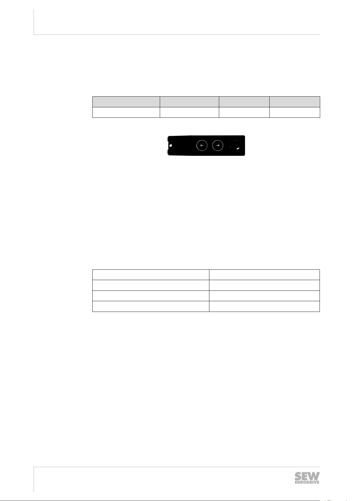
5.1 LT BG-C remote keypad .............................................................................................. 15
5.1.1 Installation in the control cabinet or control panel......................................... 16
5.1.2 Technical data............................................................................................... 17
5.1.3 Display messages......................................................................................... 17
5.2 LT ZBG OLED A remote keypad .................................................................................. 18
5.2.1 Installation in the control cabinet or control panel......................................... 18
5.2.2 Technical data............................................................................................... 19
5.2.3 Display messages......................................................................................... 19
5.3 Electrical installation ..................................................................................................... 20
5.4 System structure .......................................................................................................... 21
5.5 Startup .......................................................................................................................... 22
5.5.1 Setting the communication address.............................................................. 22
5.5.2 Changing/monitoring the parameters............................................................ 22
5.5.3 Preset setpoint speed for operation with remote keypad.............................. 22
5.5.4 Speed change in real time mode with remote keypad .................................. 23
5.5.5 Direction of rotation reversal ......................................................................... 24
5.5.6 Lock/enable parameter access ..................................................................... 24
6 Network packages ................................................................................................................... 25
6.1 Basic package (cable set A) ......................................................................................... 25
6.2 Extension package (cable set B) .................................................................................. 26
6.3 PC engineering package (cable set C) ........................................................................ 27
6.4 Cable splitter 1 to 2 ...................................................................................................... 29
21326991/EN – 05/2015
7 Prefabricated cables ............................................................................................................... 30
6.2.1 Example ........................................................................................................ 26
6.3.1 Example 1 ..................................................................................................... 27
6.3.2 Example 2 ..................................................................................................... 28
Manual – Accessories
3

Table of contents
7.1 Prefabricated cables with RJ45 connector on one end ................................................ 30
7.2 Prefabricated cables with RJ45 connectors on both ends ........................................... 30
8 Control boards......................................................................................................................... 31
8.1 OB LT LOCMO control board ....................................................................................... 31
8.1.1 Technical data............................................................................................... 31
8.1.2 Installation..................................................................................................... 32
8.1.3 Startup and operation ................................................................................... 32
8.2 LTZOBLOCMOB control board .................................................................................... 33
8.2.1 Technical data............................................................................................... 33
8.2.2 Installation..................................................................................................... 34
8.2.3 Startup and operation ................................................................................... 34
Index ......................................................................................................................................... 35
Manual – Accessories
4
21326991/EN – 05/2015

1 General information
1.1 About this documentation
General information
About this documentation
1
This documentation is an integral part of the product. The documentation is intended
for all employees who perform assembly, installation, startup, and service work on the
product.
Make sure this documentation is accessible and legible. Ensure that persons responsible for the machinery and its operation as well as persons who work on the device
independently have read through the documentation carefully and understood it. If you
are unclear about any of the information in this documentation or require further information, contact SEW‑EURODRIVE.
1.2 Rights to claim under limited warranty
Read the information in this documentation. This is essential for fault-free operation
and fulfillment of any rights to claim under limited warranty. Read the documentation
before you start working with the unit!
1.3 Other applicable documentation
This document supplements the operating instructions and limits the application notes
according to the following information. Use this document only together with the operating instructions.
1.4 Copyright notice
© 2015 SEW‑EURODRIVE. All rights reserved.
Unauthorized reproduction, modification, distribution or any other use of the whole or
any part of this documentation is strictly prohibited.
21326991/EN – 05/2015
Manual – Accessories
5

System overview
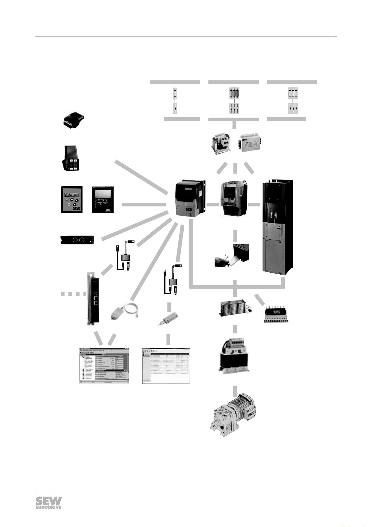
Option cards:
2nd relay output OB LT 2ROUTB
PI controller OB LT PICON-B
2nd signal relay OB LT HAVAC-B
Converter card OB LT VCON A/B
Control board OB LT LOCMO
Line choke HD
Bluetooth
Parameter module
LTBP-C
Gateway:
PROFIBUS DFP21B
EtherCAT DFE24
DeviceNet DFD11
PROFINET DFE32
Ethernet/IP DFE33B
Interbus UFI11A
Braking resistor BW
Output choke HD
(IP20/IP55)
Line
Line filter NF
LT
®
TM
TM
®
Keypad
LT BG-C
Keypad
LT ZBG OLED A
Shell parameter
software with scope
function
Cable set C
USB11A
BW internal
RJ-45
Cable sets
A, B, C
RJ-45
RJ-45
System overview of MOVITRAC® LTE-B
2
2 System overview
2.1 System overview of MOVITRAC® LTE-B
System
overview of
MOVITRAC
® LTE-B
6
Manual – Accessories
9007205070153099
21326991/EN – 05/2015
2.2 System overview of MOVITRAC® LTP-B
Output choke HD
Braking resistor
BW internal
MOVITOOLS
MotionStudio
3 × 200 – 240 V,
3 × 380 – 480 V
3 × 500 – 600 V
1 × 200 – 240 V
Braking resistor BW
Option cards:
Relay outputs
Digital I/O
Encoder card TTL
Encoder card HTL
PROFIBUS
PROFINET
EtherNet/IP
EtherCAT
DeviceNet
MODBUS TCP
POWERLINK
MOVI-PLC /
UOH-/DFxGateway
Keypad
LT BG-C
Keypad
LT ZBG OLED A
Bluetooth
Parameter module
LTBP-C
1 card slot in
inv er te r
LTX Servo-Erweiterung
LTX H1A, bis BG 3
RJ-45
LT-Shell parameter
software with scope
function
PEAK USB CAN
Dongle
Frequency inverter
IP55 /
IP20
USB11A
RJ-45
RJ-45
Control board
Cable s ets
A, B, C
Cabel set C
RJ-45
®
®
TM
TM
OBLT 3ROUT-A
OBLT IO-A
OBLT ENC-A
OBLT ENC-B
LT FP 11A
LT FE 32A
LT FE 33A
LT FE 24A
LT FD 11A
LT FE 31A
LT FE 25A
®
®
Line choke ND Line filter NF
System overview
System overview of MOVITRAC® LTP-B
2
System
overview of
MOVITRAC
® LTP-B
9007208545763979
21326991/EN – 05/2015
Manual – Accessories
7
Parameter module
Parameter module
3
3 Parameter module
3.1 Parameter module
The parameter module is exclusively designed for operation in the RJ45 port of the
frequency inverter.
Type Part number LTE-B LTP-B
LTBP-C 18241549 X X
X = available − = not available
9007202440910859
• Functionality:
– Saves data from the frequency inverter to the parameter module.
– Saves data simultaneously from both frequency inverter types to the parameter
module.
– Integrated parameter lock. Prevents overwriting of saved parameters if activa-
ted.
– Loads data back from the parameter module to the frequency inverter.
– Bluetooth® interface for communication between engineering software LT Shell
and MOVITRAC® LT or directly with the parameter module.
3.1.1 Technical data
Degree of protection IP20, NEMA 1
Ambient temperature during operation -10 to +50 °C
Range <10 m, EMC dependent
Data transmission Bluetooth
®
Manual – Accessories
8
21326991/EN – 05/2015
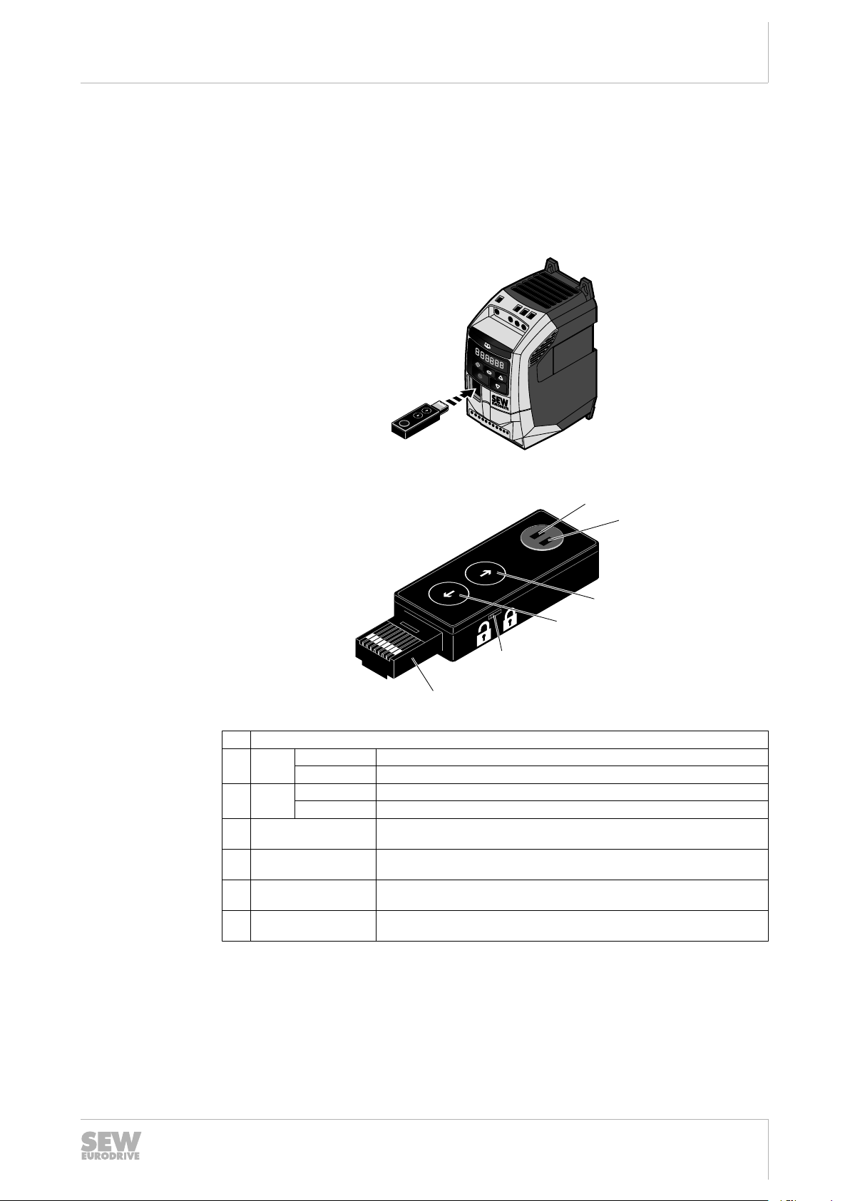
3.2 Installation, startup, and operation
MOVITRAC
®
LT
1
3
5
7
9
11
2
4
6
8
10
[1]
[2]
[3]
[4]
[5]
[6]
3.2.1 Directly at the frequency inverter
Parameter module
Installation, startup, and operation
3
1. Check the frequency inverter connection.
2. Remove the protection caps from the parameter module and insert the parameter
module into the frequency inverter slot RJ45.
13663204747
Transfer parameter set
21326991/EN – 05/2015
13642864139
Status LEDs
[1] Green Steady light Power okay, frequency inverter detected
Flashing Charging processes
[2] Blue Steady light Bluetooth ready
Flashing Bluetooth communication active
[3] [Read parameters]
button
[4] [Write parameters]
button
[5] Locking switch For locking the parameter module to inhibit overwriting of the parameter set.
[6] Parameter module in-
terface
Press the button [3] for downloading the data to the parameter module or [4] for uploading data to the frequency inverter.
For copying parameters from the frequency inverter to the parameter module.
For copying parameters from the parameter module to the frequency inverter.
The "Copy parameter" function is deactivated.
Connection via RJ45 slot at frequency inverter.
If the frequency inverter display shows PASS-r, the parameter set was successfully
copied to the parameter module.
Manual – Accessories
9

Parameter module
Installation, startup, and operation
3
If the frequency inverter display shows PASS-t, the parameter set was successfully
copied to the frequency inverter.
Locking or unlocking the parameter module
Frequency inverter display
The parameter module is equipped with a locking switch [5] with 2 positions.
1. Locked:
• Parameter set can be read in the LT Shell software.
• Parameter set cannot be changed.
• Parameter set cannot be transferred from the frequency inverter to the parameter module.
2. Unlocked:
• Read and write possible (free memory access).
The parameter module status is displayed on the frequency inverter display.
Display Description
PASS-r The parameter module successful read/saved the frequency inverter
parameters.
OS-Loc The parameter module is locked. Attempt to read parameter from fre-
quency inverter with activated parameter module lock.
FAiL-r The parameter module could not read parameters from the frequen-
cy inverter.
PASS-t The parameter module successfully transferred the parameters to
the frequency inverter. Writing of parameters to the frequency inverter.
FAiL-P The power ratings of the parameter stored in the parameter module
do not match the power ratings of the programmed frequency inverter.
FAiL-t The parameter module could not transfer the parameter set to the
frequency inverter.
no-dAt No parameter data was saved in the parameter module.
dr-Loc The frequency inverter parameters were locked. No new parameter
settings could be transferred. Unlock the parameter set of the frequency inverter.
dr-rUn Frequency inverter is running and cannot accept any new parameter
settings. Stop the frequency inverter before programming.
10
tyPE-E The parameters for the frequency inverter type saved in the parame-
ter module do not match the frequency inverter type to be programmed (only writing).
tyPE-F The parameter module does not yet support the programmed fre-
quency inverter type.
21326991/EN – 05/2015
Manual – Accessories
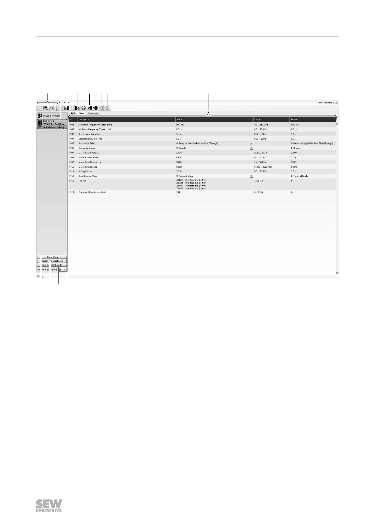
3.2.2 With LT Shell software
[9][8]
[7]
[6][5]
[4][3]
[1]
[2]
[10] [11][12][13]
Parameterization user interface
A Bluetooth® interface at the PC is required for communication with PC.
Parameter module
Installation, startup, and operation
3
21326991/EN – 05/2015
[1] Tool selection menu:
• Parameter editor
• Drive monitor
• Scope/ Data logger tool
[2] Shows the units in the network [10] Offline mode
[3] Open, save parameter file [11] Network is scanned for drives.
[4] Set unit to factory setting [12] Starts real time edit mode.
[5] Transfer parameter set from selected drive
(download)
[6] Transfer parameter set to the selected drive
(upload)
Proceed as follows to change the parameter values via the PC:
1. Download the software from the SEW‑EURODRIVE website.
2. Check the frequency inverter connection.
3. Remove the protection caps from the parameter module. Insert the parameter
module into the frequency inverter RJ45 slot.
4. Couple the parameter module with the PC via Bluetooth®. Enter the coupling code
("0000") of the parameter module.
5. Select an outgoing port for the parameter module using the PC. This connection is
used by the PC software.
[7] Transfer parameter set from parameter
module
[8] Transfer parameter set to the parameter
module
[9] Parameter display
[13] Defines the number of drives that are to be
scanned during scan mode.
12804199691
Manual – Accessories
11
Parameter module
Installation, startup, and operation
3
6. Start the software LT-Shell V4.0.exe.
7. The parameter editor is displayed.
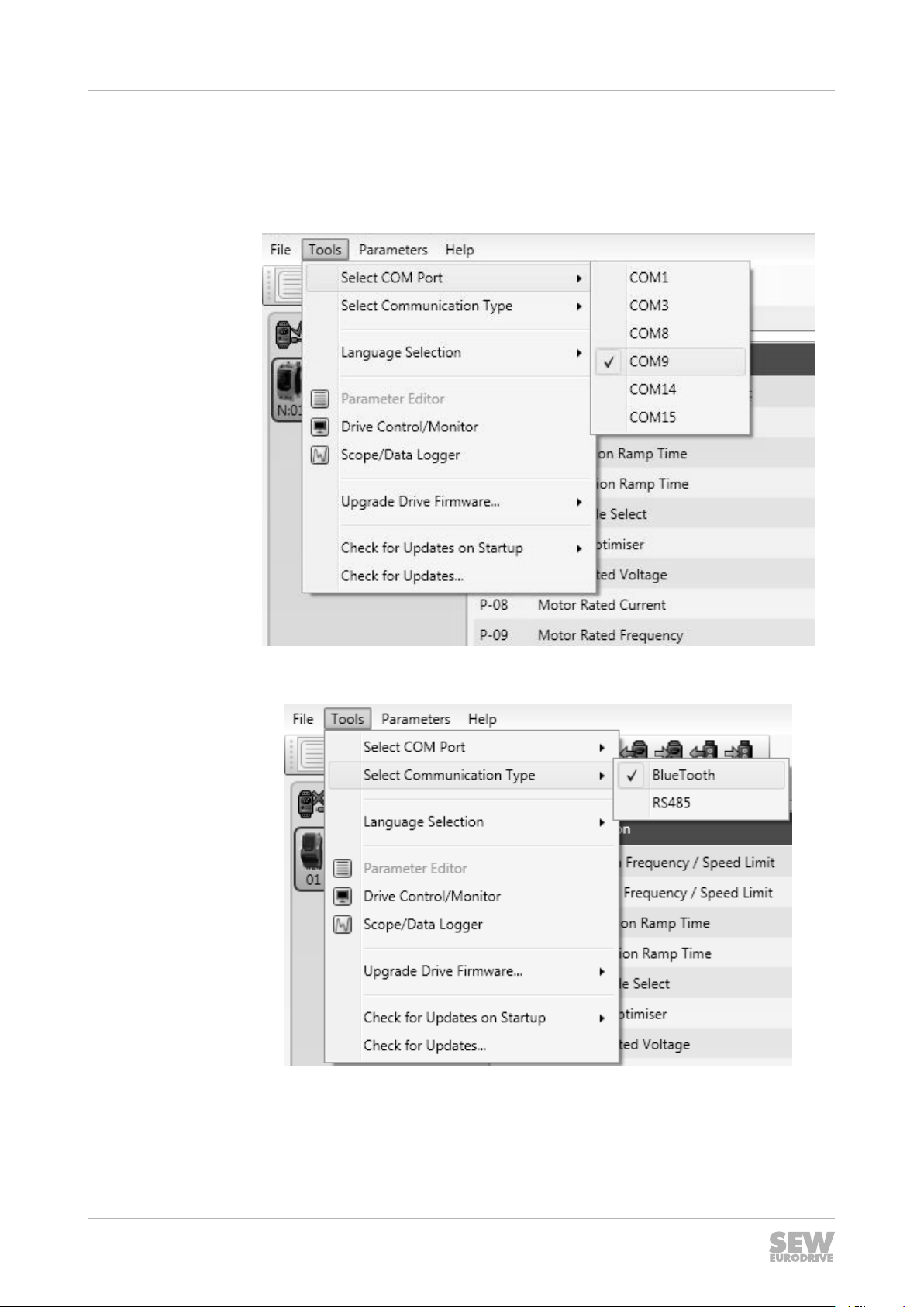
8. Select the COM port of the PC/laptop to which the frequency inverter is connected
via the parameter module.
13102428043
9. Choose the communication Bluetooth®.
13642995211
10.Scan the network for existing drives [11].
11.Read the frequency inverter parameter set using the button [5]. Or read the parameter module parameter set using the button [7].
21326991/EN – 05/2015
12
Manual – Accessories
 Loading...