

Page 1
T
MOVITRAC
®
31C
Frequency Inverters
Operating Instructions
Edition 07/2000
08/198/96
U
C
®
0
0
0
2
0
1
/
9
1
0
9
2
2
9
0
L
U
®
L
Page 2

General Notes
Phone: 800.894.0412 - Fax: 888.723.4773 - Web: www.clrwtr.com - Email: info@clrwtr.com
Always follow the warning and safety notes contained in this user manual! Safety notes are:
Electrical hazard,
Mechanical hazard,
Important instructions
A
requirement for fault-free operation
that these
instructions and remarks
e.g. when working on live equipment.
e.g. when working on hoists.
for safe and fault-free operation.
and fulfillment of any rights to claim under guarantee is
are followed.
Therefore read these instructions carefully
before you start working with the unit!
These
operating instructions
contain
important information for servicing. They should therefore
be kept in the vicinity of the unit.
Application Restrictions
The MOVITRAC
®
31C units are frequency inverters for industrial and commercial drive systems for
operation of three-phase AC squirrel-cage asynchronous motors. Other loads must not be oper-
ated with the inverters.
The installation site must be free of dust, dry (without danger of moisture condensation) and lock-
able (e.g. switch cabinet). All specifications concerning technical data and permissible conditions
at the equipment location must be observed.
Where applicable, commissioning (starting normal operation) is prohibited, unless the machine
complies with the EMC guideline 89/336/EWG and the conformity of the finished product with the
machine guideline 89/392/EWG is verified (observe EN 60204).
Unless otherwise specifically indicated, the following is prohibited:
Implementation in areas subject to explosion hazards
Implementation in the vicinity of oils, acids, gas, fumes, dusts, radiation, etc.
Implementation in non-stationary applications where mechanical vibration and impact loads
occur which exceed the limits stipulated by EN50178.
Implementation in applications where the inverter alone (without a higher-level safety system)
is responsible for safety tasks which must guarantee the safety of persons and machinery.
Disposal (please observe the applicable waste disposal regulations):
Depending on the material they are made of, unit components are to be disposed of in accordance
with the applicable waste disposal regulations for:
electronics waste (pcbs), plastic material (housing), sheet metal, copper, etc.
For further technical information as well as selection notes please refer to the
MOVITRAC
®
31C Frequency Inverter Catalog, publication no. 0922 9116.
For further information about the synchronous operation control option, the IPOS positioning con-
trol option and the fieldbus options (PROFIBUS and INTERBUS) please refer to the respective user
manuals.
2
MOVITRAC® 31C Operating Instructions
Page 3
Contents
Phone: 800.894.0412 - Fax: 888.723.4773 - Web: www.clrwtr.com - Email: info@clrwtr.com
Page
1 Safety Notes .............................................................................................4
2 Installation...............................................................................................5
2.1 Type designation, nameplate and option label .................................................................5
2.2 MOVITRAC
2.3 MOVITRAC
2.4 MOVITRAC
2.5 Installation instructions ...................................................................................................9
2.6 Installation for electromagnetic compatibility ................................................................10
2.7 UL-compliant installation...............................................................................................11
2.8 Wiring diagram for the basic unit...................................................................................12
2.9 Assignment of braking resistors, chokes and filters ......................................................15
2.10 MOVITRAC
2.11 Connecting the RS-232 serial interface (USS21A options) ...........................................19
2.12 Connecting the RS-485 serial interface (USS21A option)..............................................19
2.13 Installation of option cards ............................................................................................ 20
2.14 Wiring diagram and terminal description for the FEA31C option ...................................21
2.15 Wiring Diagram and Terminal Description for the FIO31C Option..................................22
2.16 Wiring diagram and terminal description for the FEN31C/FPI31C option.......................23
2.17 Wiring diagram and terminal description for the FIT31C option ....................................24
2.18 Connecting the incremental encoder.............................................................................25
®
31C, Size 0 .................................................................................................6
®
31C, Sizes 1 and 2......................................................................................7
®
31C, Sizes 3 and 4......................................................................................8
®
31C, size 0 with braking resistor ..............................................................18
3 Startup.................................................................................................. 26
3.1 Preliminary work and aids .............................................................................................26
3.2 Short-cut startup with the FBG31C keypad....................................................................27
3.3 Starting the motor .........................................................................................................29
3.4 Startup examples...........................................................................................................32
3.5 Complete parameter list.................................................................................................39
4 Operation and Service ............................................................................... 47
4.1 Operating displays .........................................................................................................47
4.2 Fault information............................................................................................................51
4.3 Fault signals...................................................................................................................52
4.4 SEW Electronics Service................................................................................................55
5 Technical Data ........................................................................................ 56
5.1 Basic units .....................................................................................................................56
®
5.2 MOVITRAC
5.3 MOVITRAC
5.4 MOVITRAC
31C...-233 (230 V Units) ..........................................................................57
®
31C...-503 (400/500 V Units) ...................................................................59
®
31C electronics data.................................................................................64
6 Index.................................................................................................... 65
Any revisions to edition
01/99
are indicated by a gray bar in the margin.
MOVITRAC® 31C Operating Instructions
3
Page 4

1 Safety Notes
Phone: 800.894.0412 - Fax: 888.723.4773 - Web: www.clrwtr.com - Email: info@clrwtr.com
1 Safety Notes
Installation and startup
Never install or start-up damaged products.
ping company immediately.
Installation, startup and servicing
nel
with the relevant training in accident prevention, in compliance with the valid regulations
(e.g. EN 60204, VBG 4, DIN VDE 0100/0113/0160).
The relevant instructions
observed!
Protective measures
(e.g. EN 60204 or EN 50178).
Necessary protective measure: Unit must be grounded.
Necessary protective equipment: Overcurrent protection devices (fuses).
The unit meets all requirements for secure separation
according to EN 50178. To guarantee safe and reliable separation, all
must also meet the
Ensure that the
mains
by taking
and
equipment
requirements for safe and reliable disconnection
connected motor does not start on its own when the unit is connected to the
appropriate measures (e.g. removing the electronics terminal block)
of the inverter may only be performed by
for
installation
must be chosen according to the
Make a complaint about the damage to the ship-
qualified person-
and
startup
of the motor and brake
applicable standards
of power and electronics terminals
current circuits connected
.
must be
.
Operation and service
Before
ous voltages
off.
When the
present on all subassemblies except the control electronics. The unit must be kept closed during
operation.
Dangerous voltages are present on the
terminals when the unit is in operation
and the motor is at rest.
If the
indication
Internal safety functions
Remedying the cause of the fault or resetting
If, for safety reasons,
connected from the mains
Reset function (P860) is prohibited
removing the front cover
can remain present for
front cover is removed
operating indicator LED V1
that the unit is disconnected from the mains or is
in the unit or
this is not admissible
, the
inverter must be disconnected from the mains. Danger-
up to 10 minutes after the power supply has been turned
the unit has enclosure class
output terminals
. This is also the case when the output stage is disabled
or any of the other status indicators
mechanical blocking
the unit can cause the drive
for the driven machine, the
before remedying the fault. In this case, the activation of the
.
IP 00. Dangerous voltages
and the connected
are off,
de-energized
can cause a
.
to restart by itself
inverter must be dis-
cables and motor
it
is not an
motor standstill
are
.
.
Auto-
4
MOVITRAC® 31C Operating Instructions
Page 5

2 Installation
Phone: 800.894.0412 - Fax: 888.723.4773 - Web: www.clrwtr.com - Email: info@clrwtr.com
2.1 Type designation, nameplate and option label
Type designation, example:
Installation 2
MOVITRAC 31 C 110 - 503 - 4 - 00
®
Version:
Quadrants:
Type of supply:
Rated supply voltage:
Recommended motor power:
Version C
Type series 31
Nameplate, example:
The nameplate is mounted on the side of the unit.
00 = Standard
4 = 4-Q (with brake chopper)
3 = 3-phase
50 = 380...500 V ; 23 = 200...240 V
AC AC
110 = 11 kW; 150 = 15 kW
01552AEN
Fig. 1: Nameplate
00593AXX
Option label, example:
®
All MOVITRAC
31C inverters come with an option label specifying the option cards installed at the
plant. If an option card is installed at a later date, the option must be marked on the option label.
®
Example: MOVITRAC
Fig. 2: Option label
31C with FEA31C.
FEA
X
FRN
FEN
FRS
FFI
FFP
Options
FFD
FPI
FIO
FIT
31C
31C
31C
31C
31C
31C
31C
31C
31C
31C
00596AEN
MOVITRAC® 31C Operating Instructions
5
Page 6
2 Installation
Phone: 800.894.0412 - Fax: 888.723.4773 - Web: www.clrwtr.com - Email: info@clrwtr.com
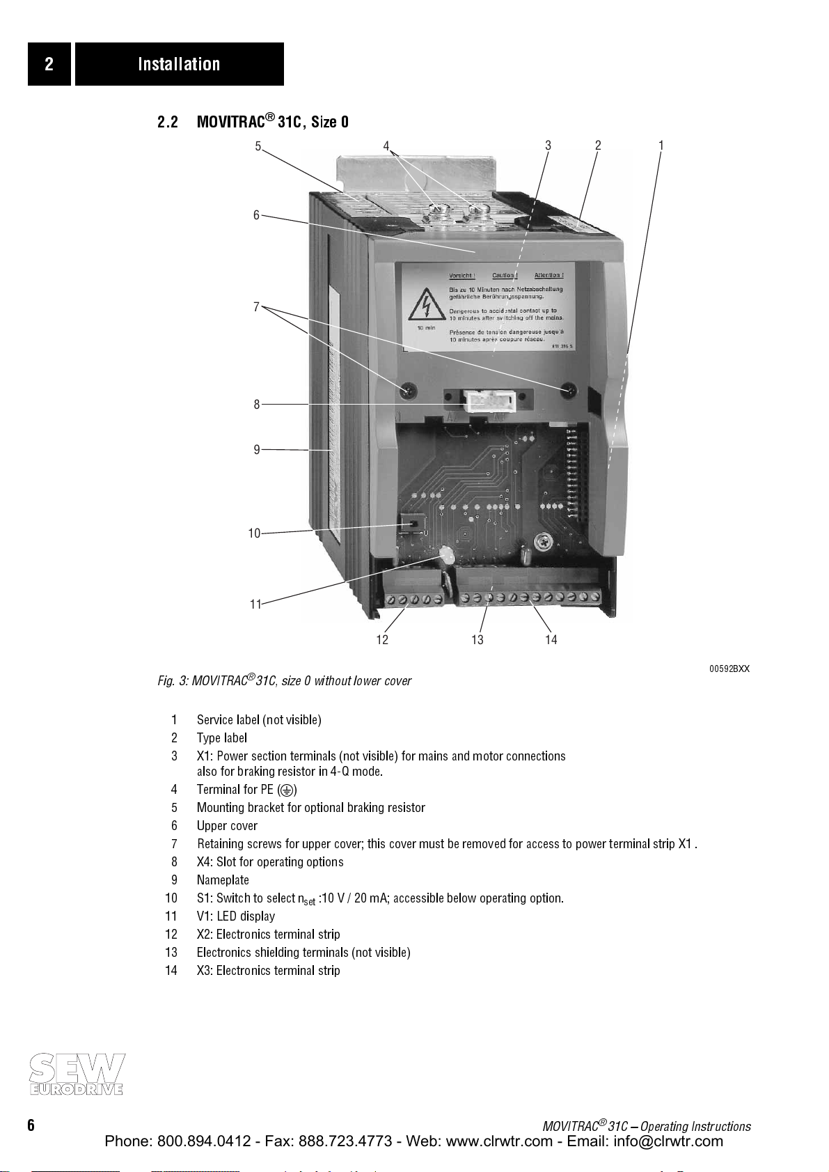
2.2 MOVITRAC® 31C, Size 0
5
6
7
8
9
4
123
10
11
12 13 14
Fig. 3: MOVITRAC® 31C, size 0 without lower cover
1 Service label (not visible)
2 Type label
3 X1: Power section terminals (not visible) for mains and motor connections
also for braking resistor in 4-Q mode.
4 Terminal for PE (y)
5 Mounting bracket for optional braking resistor
6 Upper cover
7 Retaining screws for upper cover; this cover must be removed for access to power terminal strip X1 .
8 X4: Slot for operating options
9 Nameplate
10 S1: Switch to select n
11 V1: LED display
12 X2: Electronics terminal strip
13 Electronics shielding terminals (not visible)
14 X3: Electronics terminal strip
:10 V / 20 mA; accessible below operating option.
set
00592BXX
6
MOVITRAC® 31C Operating Instructions
Page 7
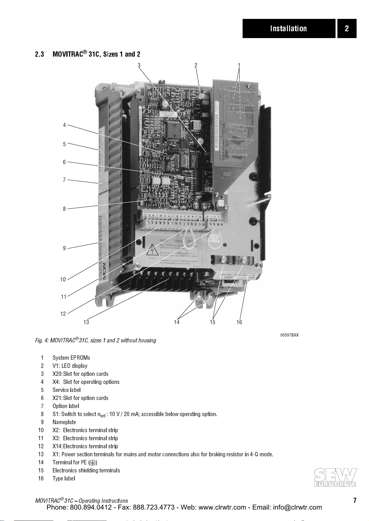
2.3 MOVITRAC
Phone: 800.894.0412 - Fax: 888.723.4773 - Web: www.clrwtr.com - Email: info@clrwtr.com
4
5
6
7
®
31C, Sizes 1 and 2
Installation 2
123
8
9
10
11
12
13 14 15 16
Fig. 4: MOVITRAC® 31C, sizes 1 and 2 without housing
1 System EPROMs
2 V1: LED display
3 X20:Slot for option cards
4 X4: Slot for operating options
5 Service label
6 X21:Slot for option cards
7 Option label
8 S1: Switch to select n
9 Nameplate
10 X2: Electronics terminal strip
11 X3: Electronics terminal strip
12 X14: Electronics terminal strip
13 X1: Power section terminals for mains and motor connections also for braking resistor in 4-Q mode.
14 Terminal for PE (y)
15 Electronics shielding terminals
16 Type label
: 10 V / 20 mA; accessible below operating option.
set
00597BXX
MOVITRAC® 31C Operating Instructions
7
Page 8
2 Installation
Phone: 800.894.0412 - Fax: 888.723.4773 - Web: www.clrwtr.com - Email: info@clrwtr.com
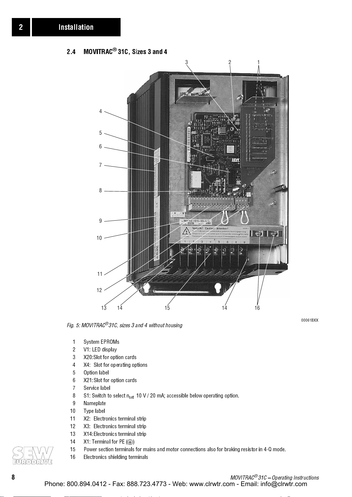
2.4 MOVITRAC® 31C, Sizes 3 and 4
123
4
5
6
7
8
9
10
11
12
13 14 15 14 16
Fig. 5: MOVITRAC® 31C, sizes 3 and 4 without housing
1 System EPROMs
2 V1: LED display
3 X20:Slot for option cards
4 X4: Slot for operating options
5 Option label
6 X21:Slot for option cards
7 Service label
8 S1: Switch to select n
9 Nameplate
10 Type label
11 X2: Electronics terminal strip
12 X3: Electronics terminal strip
13 X14:Electronics terminal strip
14 X1: Terminal for PE (y)
15 Power section terminals for mains and motor connections also for braking resistor in 4-Q mode.
16 Electronics shielding terminals
10 V / 20 mA; accessible below operating option.
set
00061BXX
8
MOVITRAC® 31C Operating Instructions
Page 9

2.5 Installation instructions
Phone: 800.894.0412 - Fax: 888.723.4773 - Web: www.clrwtr.com - Email: info@clrwtr.com
Safety instructions (→ Sec. 1, Page 4) must be strictly observed during installation!
Use only original connection components!
®
Observe the
tightening torques
of the MOVITRAC
31C power terminals:
Size 0 → 1.5 Nm (13.3 lb.in) / Size 1 → 0.6 Nm (5.3 lb.in) /
Size 2 → 1.5 Nm (13.3 lb.in) / Sizes 3 and 4 → 3.5 Nm (31 lb.in)
Observe minimum required ventilation space
clearance of
Units must be
100 mm (4 in) above and below
mounted vertically
. Other mounting positions are not permissible!
of units (sufficient cooling)! Leave a minimum
the unit. No lateral clearance required.
Installation 2
The MOVITRAC® 31C is designed for operation on
earthed neutral point (TN and TT power systems)
However, operation on voltage power systems with a non-earthed neutral point (for example
power systems
) is also
permitted
. SEW recommends using earth-leakage monitors with pulse-
voltage power systems with a directly
.
IT
code measurement in voltage systems with non-earthed neutral points (IT systems). This pre-
vents the earth capacitance of the inverter from inadvertently triggering the earth-leakage moni-
tor. The EMC limit values for interference emission are not specified for voltage systems with a
non-earthed neutral point (IT power systems). Line filter effectiveness is extremely limited.
With
more than four units
units:
connect a 3-phase line choke
Run
power cables
and
Mains power cable:
PE mains connection (→ EN 50178):
on a single
mains contactor
dimensioned for the total current of all
in series to limit the inrush current.
electronic leads
in separate cable ducts.
based on input rated current Iin at rated load (Data →
If cross-section of PE conductor is < 10 mm² (AWG8), a
Sec. 5).
second lead with the cross-section of the mains connection cable must be run parallel to the PE
conductor via separate terminals or a copper PE conductor with a cross-section of 10 mm²
(AWG8) must be used. If the mains connection cable is ≥ 10 mm² (AWG8), a copper PE conduc-
tor with the cross-section of the mains connection cable must be used. During operation leakage
currents > 3.5 mA can occur.
Motor cable:
The
input fuses
junction. (→
based on the output rated current IN (Data →
Sec. 5).
must be installed at the beginning of the power cable, directly after the busbar
Sec. 2.8.1: F11/F12/F13). Use fuse types D, DO, NH or power circuit breakers.
An
earth leakage circuit-breaker
currents > 3.5 mA
can occur during normal inverter operation.
Alternate operation of two motors from one inverter:
for each of the two motors cables.
is
not permissible as the sole protection device, as leakage
a changeover contactor must be provided
Changeover contactors may only be actuated when the
inverter is disabled!
Only connect a
Recommendation:
Binary inputs
voltage proof
Connection of braking resistors:
power cable, with a cross-section based on the inverter rated current. (Data →
the braking resistor with a bimetallic relay (→
Technical Data of Braking Resistors (→
resistive/inductive load (motor)
to the
inverter output
, no capacitive load!
Observe a minimum switch-off time of 10 s for the mains contactor K11.
are
opto-isolated
. Connecting an
.The
binary outputs
external voltage source
are
short-circuit-proof
to the binary outputs can
, but
Use two closely adjacent twisted wires or a 2-core shielded
Sec. 5). Protect
Sec. 2.8.1: F16) tripping current according to
Sec. 2.9).
not external-
damage
them!
Operation braking resistors: In normal operation the connection leads to the braking resistor
carry a high DC voltage (approx. 900 V).
design with appropriate touchguard. When loaded with P
reaches
high temperatures
. Choose the mounting position accordingly (for example on the top
If required, mount braking resistors in flat-pack
, the
surface
N
of the braking resistor
of the switch cabinet).
MOVITRAC® 31C Operating Instructions
9
Page 10
2 Installation
Phone: 800.894.0412 - Fax: 888.723.4773 - Web: www.clrwtr.com - Email: info@clrwtr.com
2.6 Installation for electromagnetic compatibility
The control leads must be shielded.
The shield must be earthed by the most direct route possible, with a wide-area contact to
ground at both ends. If necessary, one end may be earthed via an interference suppression
capacitor (220 nF/50 V) to prevent earth loops. In the case of double-shielded cable, earth the
outer shield at the MOVITRAC
Running the cables in separate, earthed metal ducts or conduits is also effective as shielding.
Connect the MOVITRAC® and all accessories to earth in compliance with high frequency require-
ments (wide-area metallic contact between unit housing and ground, i.e. switch cabinet moun-
ting plate not painted).
EMC module EF...-503 (contains input filter and output choke)
EF014/030/075-503: Mount the EMC module together with the MOVITRAC® 31C unit onto the
conductive mounting surface in the switch cabinet.
EF220/450-503: First mount the EMC module onto the conductive mounting surface with four
screws in the switch cabinet, then mount the MOVITRAC
onto the EMC module.
Input filter NF...-...
Mount the NF.. input filter close to the corresponding MOVITRAC® , but
ventilation space required
Keep the connection cable between the input filter and the MOVITRAC® as short as possible:
a maximum lead length of 400 mm (15 in) is permissible. Unshielded, twisted-conductor
cable is sufficient. Use also unshielded cables for the connection between the mains and the
input filter.
If multiple inverters are connected to one input filter, the input filter must be connected either
directly at the switch cabinet input or in the immediate vicinity of the inverter. The correct
input filter is determined from the total current of all inverters.
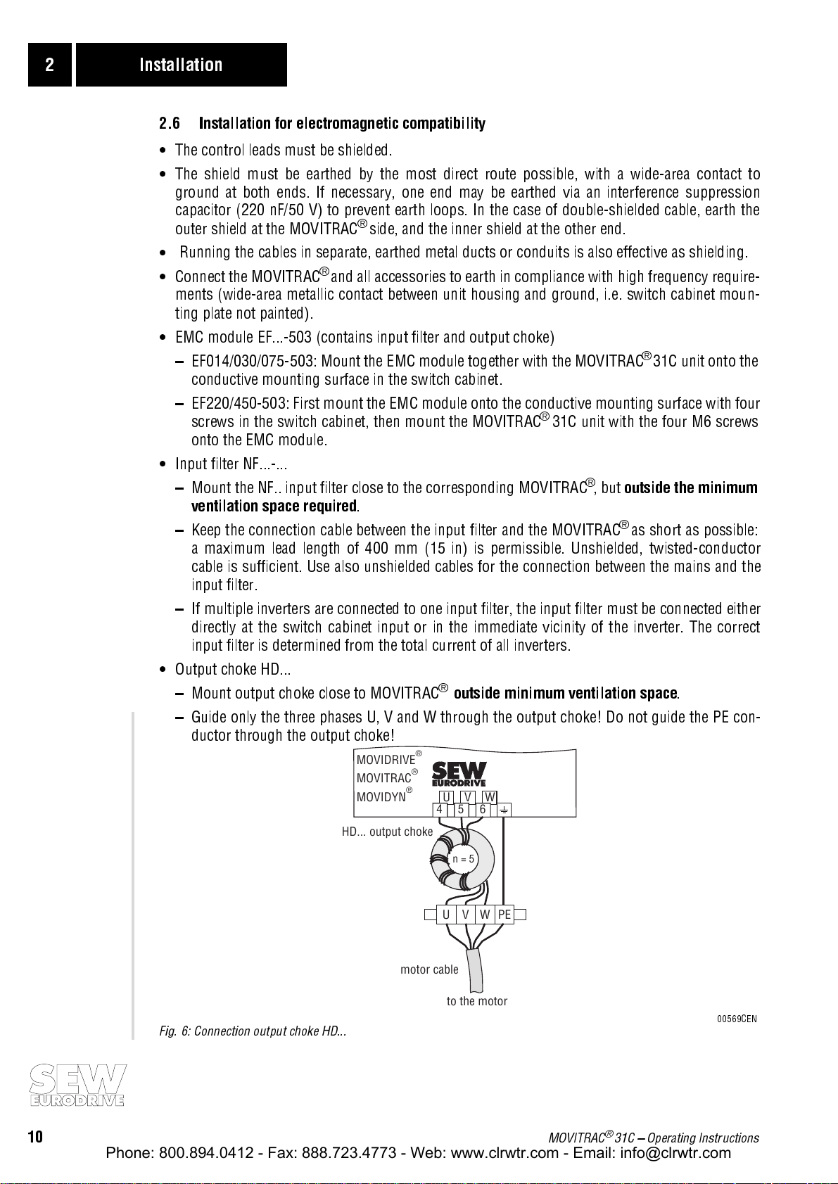
Output choke HD...
Mount output choke close to MOVITRAC®
®
side, and the inner shield at the other end.
®
31C unit with the four M6 screws
.
outside minimum ventilation space
outside the minimum
.
Guide only the three phases U, V and W through the output choke! Do not guide the PE con-
ductor through the output choke!
MOVIDRIVE
MOVITRAC
MOVIDYN
HD... output choke
Fig. 6: Connection output choke HD...
®
®
®
UVW
456
UVWPE
motor cable
n = 5
to the motor
00569CEN
10
MOVITRAC® 31C Operating Instructions
Page 11
Installation 2
Phone: 800.894.0412 - Fax: 888.723.4773 - Web: www.clrwtr.com - Email: info@clrwtr.com
2.7 UL-compliant installation
For UL-compliant installation observe the following instructions:
Use only copper leads as connection cable with the following temperature range:
- for MOVITRAC
- for MOVITRAC
The permissible tighentening torque values of the MOVITRAC® 31C power terminals are as fol-
lows:
Size 0 → 1.5 Nm (13.3 lb.in)
Size 1 → 0.6 Nm (5.3 lb.in)
Size 2 → 1.5 Nm (13.3 lb.in)
Size 3 → 3.5 Nm (31 lb.in)
Size 4 → 3.5 Nm (31 lb.in)
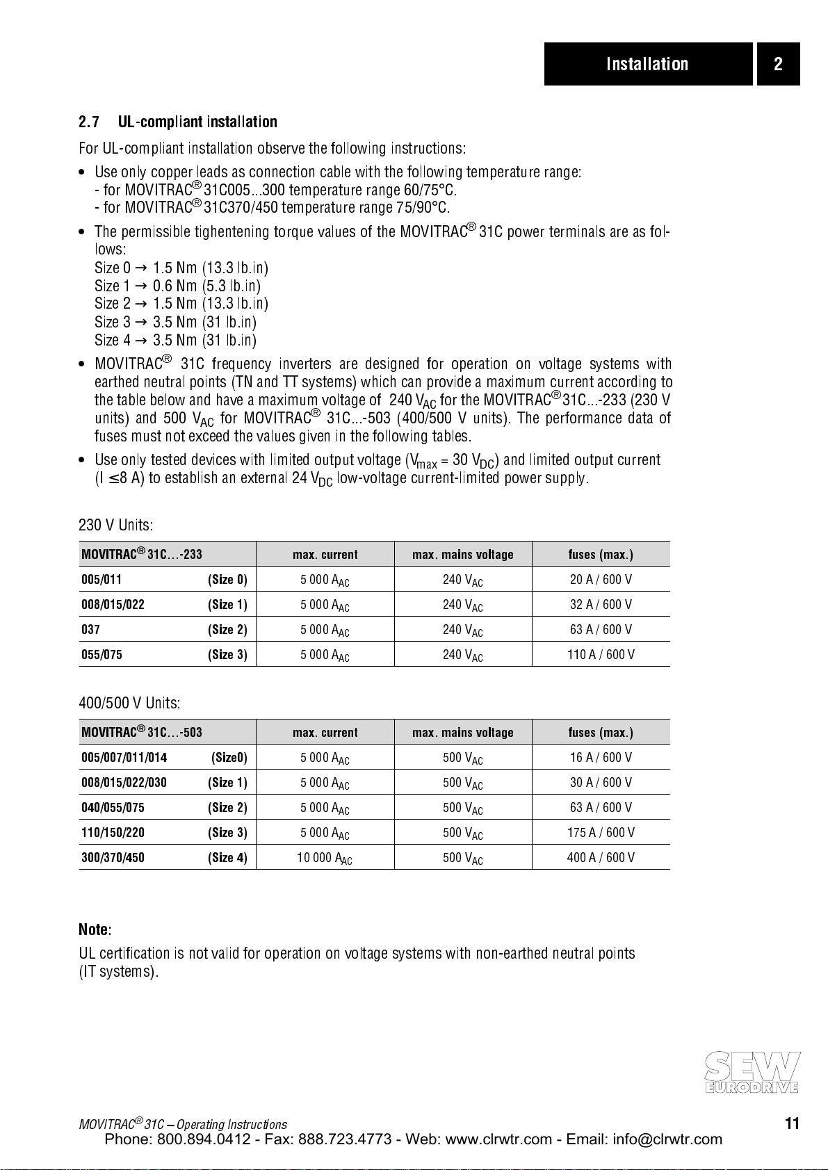
MOVITRAC® 31C frequency inverters are designed for operation on voltage systems with
earthed neutral points (TN and TT systems) which can provide a maximum current according to
the table below and have a maximum voltage of 240 V
units) and 500 V
fuses must not exceed the values given in the following tables.
Use only tested devices with limited output voltage (V
(I ≤ 8 A) to establish an external 24 V
®
31C005...300 temperature range 60/75°C.
®
31C370/450 temperature range 75/90°C.
for the MOVITRAC® 31C...-233 (230 V
AC
for MOVITRAC® 31C...-503 (400/500 V units). The performance data of
AC
= 30 VDC) and limited output current
max
low-voltage current-limited power supply.
DC
230 V Units:
MOVITRAC® 31C...-233 max. current max. mains voltage fuses (max.)
005/011 (Size 0)
008/015/022 (Size 1)
037 (Size 2)
055/075 (Size 3)
5 000 A
5 000 A
5 000 A
5 000 A
AC
AC
AC
AC
240 V
240 V
240 V
240 V
AC
AC
AC
AC
20 A / 600 V
32 A / 600 V
63 A / 600 V
110 A / 600 V
400/500 V Units:
MOVITRAC® 31C...-503 max. current max. mains voltage fuses (max.)
005/007/011/014 (Size0)
008/015/022/030 (Size 1)
040/055/075 (Size 2)
110/150/220 (Size 3)
300/370/450 (Size 4)
5 000 A
5 000 A
5 000 A
5 000 A
10 000 A
AC
AC
AC
AC
AC
500 V
500 V
500 V
500 V
500 V
AC
AC
AC
AC
AC
16 A / 600 V
30 A / 600 V
63 A / 600 V
175 A / 600 V
400 A / 600 V
Note:
UL certification is not valid for operation on voltage systems with non-earthed neutral points
(IT systems).
MOVITRAC® 31C Operating Instructions
11
Page 12
2 Installation
Phone: 800.894.0412 - Fax: 888.723.4773 - Web: www.clrwtr.com - Email: info@clrwtr.com
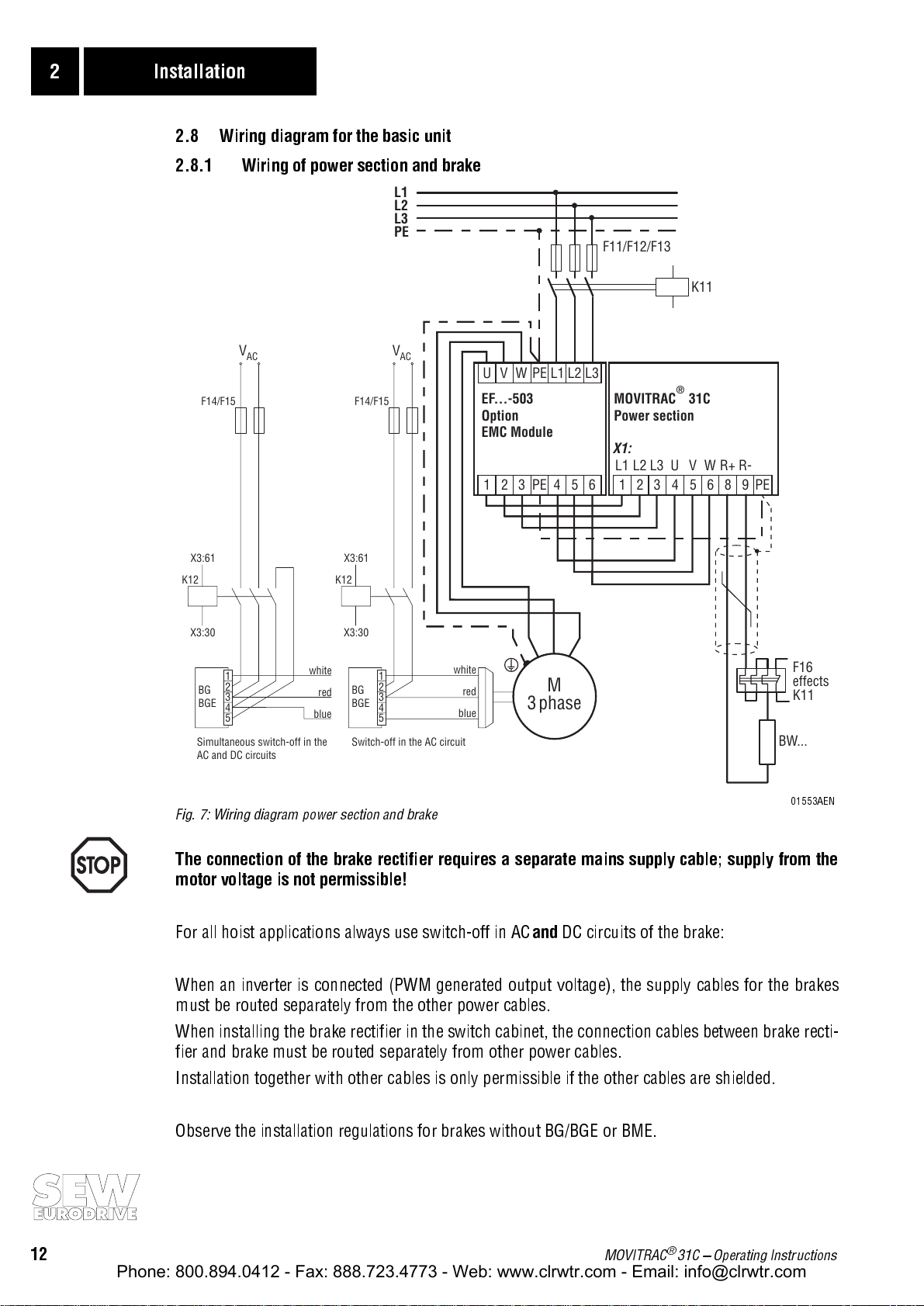
2.8 Wiring diagram for the basic unit
2.8.1 Wiring of power section and brake
L1
L2
L3
PE
F11/F12/F13
K11
F14/F15F14/F15
BG
BGE
Switch-off in the AC circuitSimultaneous switch-off in the
V
AC
1
2
3
4
5
V
AC
1
2
BG
3
BGE
4
5
AC and DC circuits
X3:61X3:61
K12K12
X3:30X3:30
white
red
blue
Fig. 7: Wiring diagram power section and brake
L1 L2 L3PEUVW
EF...-503
Option
EMC Module
13462PE5 1
white
red
blue
M
3phase
MOVITRAC 31C
®
Power section
X1:
L13L35V
R-
PE2L24U6W8R+9
F16
effects
K11
BW...
01553AEN
The connection of the brake rectifier requires a separate mains supply cable; supply from the
motor voltage is not permissible!
For all hoist applications always use switch-off in AC
and
DC circuits of the brake:
When an inverter is connected (PWM generated output voltage), the supply cables for the brakes
must be routed separately from the other power cables.
When installing the brake rectifier in the switch cabinet, the connection cables between brake recti-
fier and brake must be routed separately from other power cables.
Installation together with other cables is only permissible if the other cables are shielded.
Observe the installation regulations for brakes without BG/BGE or BME.
12
MOVITRAC® 31C Operating Instructions
Page 13
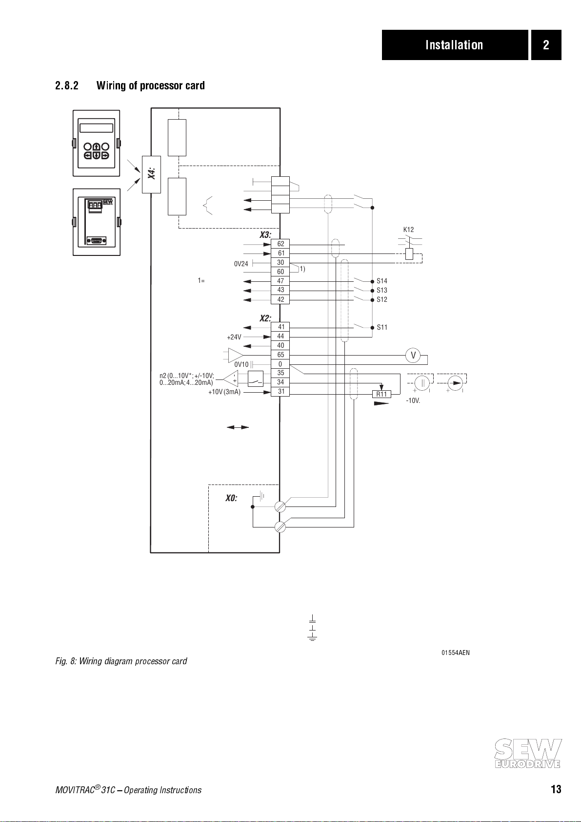
2.8.2 Wiring of processor card
Phone: 800.894.0412 - Fax: 888.723.4773 - Web: www.clrwtr.com - Email: info@clrwtr.com
Installation 2
Option Keypad
EQ
0V5 - +
RS485
RS232
Option
Ser.interfaces
USS21A
Option slots
X20/X21
X20:
X4:
Reference48/49
X21:
n13*
1/0=faultfree/fault*
Reference41-47
0/1=Ramp t1/t2*
1/0=Enable/Rapid stop*
1/0=CCW/Stop*
*Factory settings
Outputfrequency*
Measurementoutput
n2(0...10V*;+/-10V;
0...20mA;4...20mA)
0/1=n12*
0/1=n11*
Brake
1/0=CW/Stop
+24V
+24V(external)
+10V(3mA)
I-Signal
0V24
0V24
0V10
+-
S1
X14:
X3:
X2:
S1
rightleft
V-Signal
Option slots X20/X21 not available
with Size 0 (MC31C005/007/011/014)!
Terminal strip X14 not available with
Size 0 (MC31C005/007/011/014)!
Terminals 48/49 are integrated in terminal strip X3.
30
1)
60
49
48
2)
62
61
30
1)
60
47
43
42
41
44
40
65
0
35
34
31
S16
S15
Binary output signals for PLC
or external output relays;
S14
TL.61: max. 150mA/3.6W
TL.62: max. 50 mA/1.2 W
S13
(alternative contactor K12
S12
for brake switching)
S11
PWMsignal TTL
R11
K12
V
TL.34-35
V
-10V...+10V
0(4)...20mA
I
Processorpcb
Fig. 8: Wiring diagram processor card
X0:
Shieldplate
1)Jumper,factory installed;connects reference of
thebinaryinputswithunits internal ground.
2)Afterinstallinganoptionin slot X21,theterminals
48/49/60/30inthebasicunitarenotavailable.
TL.0 0V10(Referencepotential10V,analogsignals)
TL.30 0V24(Referencepotential 24V,binary signals)
Strip Protectiveearthconductor(Shield)
01554AEN
MOVITRAC® 31C Operating Instructions
13
Page 14
2 Installation
Phone: 800.894.0412 - Fax: 888.723.4773 - Web: www.clrwtr.com - Email: info@clrwtr.com
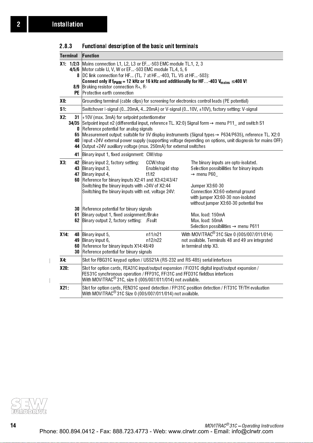
2.8.3 Functional description of the basic unit terminals
Terminal Function
X1: 1/2/3
4/5/6
8
8/9
PE
X0:
S1:
X2: 31
34/35
0
65
40
44
41
X3: 42
43
47
60
30
61
62
X14: 48
49
60
30
X4:
X20:
X21:
Mains connection L1, L2, L3 or EF...-503 EMC module TL.1, 2, 3
Motor cable U, V, W or EF...-503 EMC module TL.4, 5, 6
DC link connection for HF... (TL. 7 at HF...-403, TL. V5 at HF...-503):
Connect only if f
Braking resistor connection R+, R-
Protective earth connection
Grounding terminal (cable clips) for screening for electronics control leads (PE potential)
Switchover I-signal (0...20mA, 4...20mA) or V-signal (0...10V, ±10V), factory setting: V-signal
+10V (max. 3mA) for setpoint potentiometer
Setpoint input n2 (differential input, reference TL. X2:0) Signal form → menu P11_ and switch S1
Reference potential for analog signals
Measurement output: suitable for 5V display instruments (Signal types → P634/P635), reference TL. X2:0
Input +24V external power supply (supporting voltage depending on options, unit diagnosis for mains OFF)
Output +24V auxiliary voltage (max. 250mA) for external switches
Binary input 1, fixed assignment: CW/stop
Binary input 2, factory setting: CCW/stop The binary inputs are opto-isolated.
Binary input 3, Enable/rapid stop Selection possibilities for binary inputs
Binary input 4, t1/t2
Reference for binary inputs X2:41 and X3:42/43/47
Switching the binary inputs with +24V of X2:44 Jumper X3:60-30
Switching the binary inputs with ext. voltage 24V: Connection X3:60-external ground
Reference potential for binary signals
Binary output 1, fixed assignment:/Brake Max. load: 150mA
Binary output 2, factory setting: /Fault Max. load: 50mA
Binary input 5, n11/n21 With MOVITRAC
Binary input 6, n12/n22 not available. Terminals 48 and 49 are integrated
Reference for binary inputs X14:48/49 in terminal strip X3.
Reference potential for binary signals
Slot for FBG31C keypad option / USS21A (RS-232 and RS-485) serial interfaces
Slot for option cards, FEA31C input/output expansion / FIO31C digital input/output expansion /
FES31C synchronous operation / FFP31C, FFI31C and FFD31C fieldbus interfaces
With MOVITRAC
Slot for option cards, FEN31C speed detection / FPI31C position detection / FIT31C TF/TH evaluation
With MOVITRAC® 31C Size 0 (005/007/011/014) not available.
= 12 kHz or 16 kHz and additionally for HF...-403 V
PWM
→
menu P60_
with jumper X3:60-30 non-isolated
without jumper X3:60-30 potential free
Selection possibilities → menu P611
®
31C, size 0 (005/007/011/014) not available.
®
31C Size 0 (005/007/011/014)
mains
≤ 400 V!
14
MOVITRAC® 31C Operating Instructions
Page 15

Installation 2
Phone: 800.894.0412 - Fax: 888.723.4773 - Web: www.clrwtr.com - Email: info@clrwtr.com
2.9 Assignment of braking resistors, chokes and filters
®
2.9.1 MOVITRAC
MOVITRAC® 31C...-233 005 011 008 015 022 037 055 075
Size 0 1 2 3
Braking resistors
BW100-003 I
BW100-005 I
BW100-002 I
BW100-006 I
BW039-003 I
BW039-006 I
BW039-012 I
BW039-026 I
BW027-006 I
BW027-012 I
BW012-025 I
BW012-050 I
BW012-100 I
EMC modules
EF014-503 ID = 5 A
EF030-503 ID = 10 A
EF075-503 ID = 20 A
EF220-503 ID = 60 A
Line chokes
ND020-013ΣI
ND045-013ΣIin = 45 A
Input filters
NF008-443
NF016-443 825 719 1 B B A
NF025-443 825 718 3 B A
NF036-443 825 717 5
Output chokes
HD001 d = 50 mm (1.97 in) 813 325 5 for cable cross-sections 1.5...16 mm2 (AWG16...6)
HD002 d = 23 mm (0.91 in) 813 557 6 for cable cross-sections ≤ 1.5 mm
HD003 d = 88 mm (4.46 in) 813 558 4 for cable cross-sections ≥ 16 mm2 (AWG6)
31C...-233 (230V units)
= 0.5 A
trip
trip
trip
trip
trip
trip
trip
trip
trip
trip
trip
trip
trip
in
V
max
= 1.2 A
= 1.2 A
= 2.3 A
= 2.0 A
= 3.2 A
= 5.0 A
= 7.8 A
= 2.5 A
= 4.4 A
= 10 A
= 19 A
= 27 A
AC
= 20 A
= 440 V
RMS
RMS
RMS
RMS
RMS
RMS
RMS
RMS
RMS
RMS
RMS
RMS
RMS
AC
AC
AC
AC
AC
AC
Part number
826 266 7
826 269 1
821 700 9
821 701 7
821 687 8
821 688 6
821 689 4
821 690 8
822 422 6
822 423 4
821 680 0
821 681 9
821 682 7
Part number
826 384 1
826 385 X
826 386 8
826 553 4
Part number
826 012 5 A
826 013 3 B
Part number
825 721 3 A A
Part number
2
(AWG16)
B
A in case of rated operation (100%)
B with variable torque load (125%)
MOVITRAC® 31C Operating Instructions
15
Page 16
2 Installation
Phone: 800.894.0412 - Fax: 888.723.4773 - Web: www.clrwtr.com - Email: info@clrwtr.com
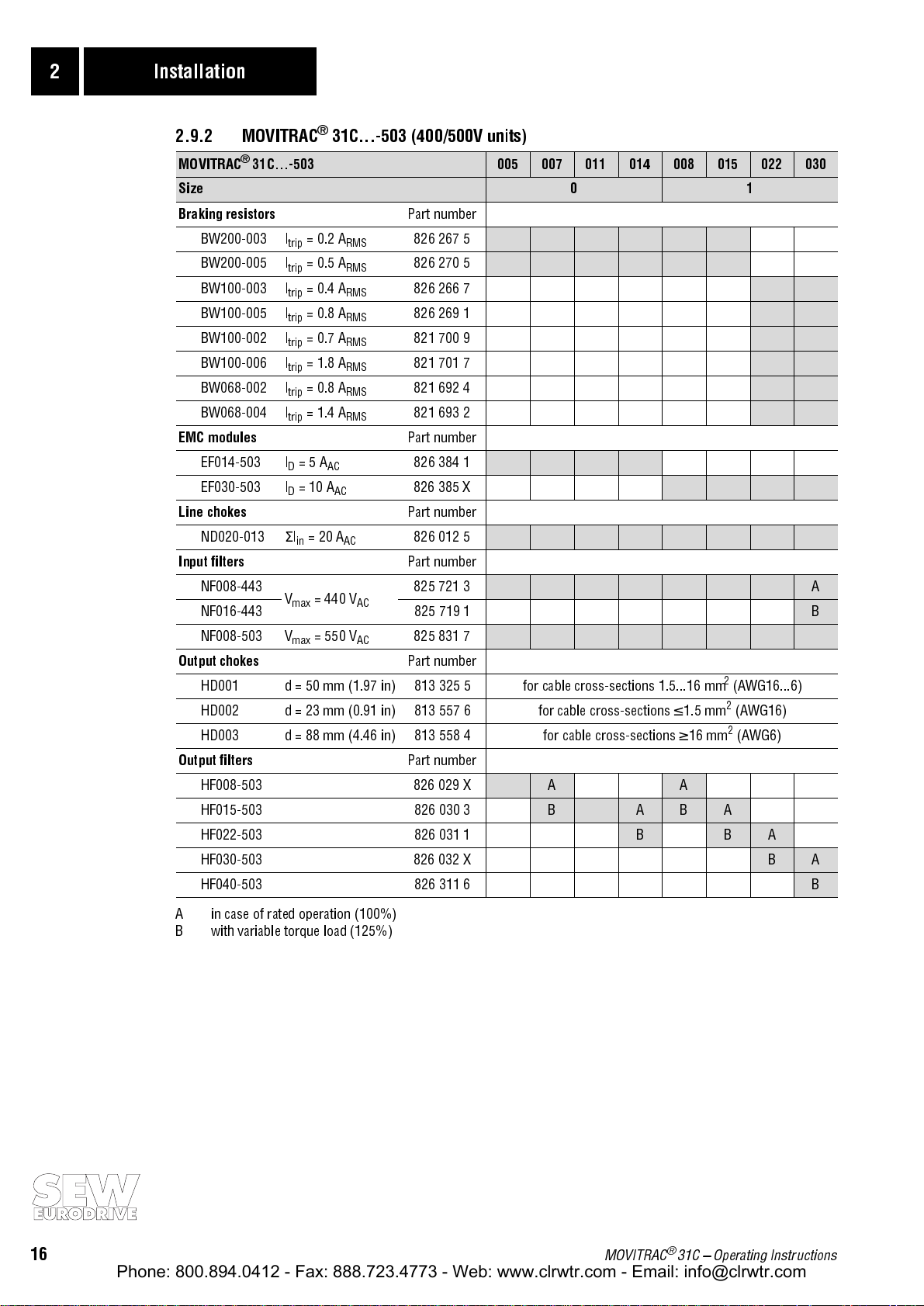
2.9.2 MOVITRAC® 31C...-503 (400/500V units)
MOVITRAC® 31C...-503 005 007 011 014 008 015 022 030
Size 0 1
Braking resistors
BW200-003 I
BW200-005 I
BW100-003 I
BW100-005 I
BW100-002 I
BW100-006 I
BW068-002 I
BW068-004 I
EMC modules
EF014-503 ID = 5 A
EF030-503 ID = 10 A
Line chokes
ND020-013ΣIin = 20 A
Input filters
NF008-443
NF016-443 825 719 1 B
NF008-503 V
Output chokes
HD001 d = 50 mm (1.97 in) 813 325 5 for cable cross-sections 1.5...16 mm2 (AWG16...6)
HD002 d = 23 mm (0.91 in) 813 557 6 for cable cross-sections ≤ 1.5 mm2 (AWG16)
HD003 d = 88 mm (4.46 in) 813 558 4 for cable cross-sections ≥ 16 mm
Output filters
HF008-503 826 029 X A A
HF015-503 826 030 3
HF022-503 826 031 1 B B A
HF030-503 826 032 X B A
HF040-503 826 311 6
trip
trip
trip
trip
trip
trip
trip
trip
V
max
max
= 0.2 A
= 0.5 A
= 0.4 A
= 0.8 A
= 0.7 A
= 1.8 A
= 0.8 A
= 1.4 A
AC
= 440 V
= 550 V
AC
RMS
RMS
RMS
RMS
RMS
RMS
RMS
RMS
AC
AC
AC
Part number
826 267 5
826 270 5
826 266 7
826 269 1
821 700 9
821 701 7
821 692 4
821 693 2
Part number
826 384 1
826 385 X
Part number
826 012 5
Part number
825 721 3 A
825 831 7
Part number
2
(AWG6)
Part number
B A B A
B
A in case of rated operation (100%)
B with variable torque load (125%)
16
MOVITRAC® 31C Operating Instructions
Page 17
Installation 2
Phone: 800.894.0412 - Fax: 888.723.4773 - Web: www.clrwtr.com - Email: info@clrwtr.com
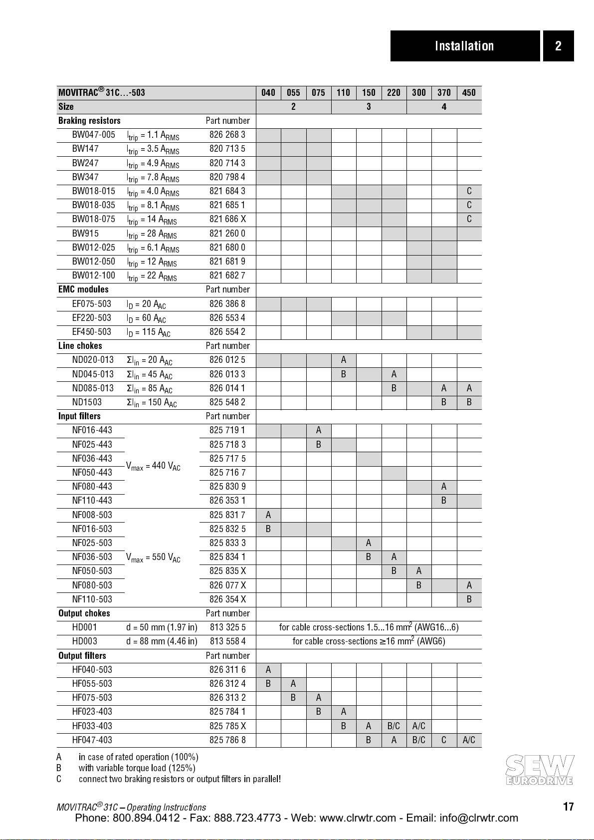
MOVITRAC® 31C...-503 040 055 075 110 150 220 300 370 450
Size 2 3 4
Braking resistors
BW047-005 I
BW147 I
BW247 I
BW347 I
BW018-015 I
BW018-035 I
BW018-075 I
BW915 I
BW012-025 I
BW012-050 I
BW012-100 I
= 1.1 A
trip
= 3.5 A
trip
= 4.9 A
trip
= 7.8 A
trip
= 4.0 A
trip
= 8.1 A
trip
= 14 A
trip
= 28 A
trip
= 6.1 A
trip
= 12 A
trip
= 22 A
trip
RMS
RMS
RMS
RMS
RMS
RMS
RMS
RMS
RMS
RMS
RMS
EMC modules
EF075-503 I
EF220-503 ID = 60 A
EF450-503 ID = 115 A
= 20 A
D
AC
AC
AC
Line chokes
ND020-013ΣI
ND045-013ΣI
ND085-013ΣI
ND1503
in
in
in
Σ
I
in
= 20 A
= 45 A
= 85 A
= 150 A
AC
AC
AC
AC
Input filters
NF016-443
NF025-443 825 718 3
NF036-443 825 717 5
NF050-443 825 716 7
V
max
= 440 V
AC
NF080-443 825 830 9 A
NF110-443 826 353 1
NF008-503
NF016-503 825 832 5
NF025-503 825 833 3 A
V
NF036-503 825 834 1
max
= 550 V
AC
NF050-503 825 835 X
NF080-503 826 077 X
NF110-503 826 354 X
Output chokes
HD001 d = 50 mm (1.97 in) 813 325 5 for cable cross-sections 1.5...16 mm
HD003 d = 88 mm (4.46 in) 813 558 4 for cable cross-sections ≥ 16 mm
Output filters
HF040-503 826 311 6
HF055-503 826 312 4
HF075-503 826 313 2
HF023-403 825 784 1
HF033-403 825 785 X
HF047-403 825 786 8
Part number
826 268 3
820 713 5
820 714 3
820 798 4
821 684 3 C
821 685 1 C
821 686 X C
821 260 0
821 680 0
821 681 9
821 682 7
Part number
826 386 8
826 553 4
826 554 2
Part number
826 012 5 A
826 013 3 B A
826 014 1 B A A
825 548 2 B B
Part number
825 719 1 A
B
B
825 831 7 A
B
B A
B A
B A
Part number
2
(AWG16...6)
2
(AWG6)
Part number
A
B A
B A
B A
B A B/C A/C
B A B/C C A/C
B
A in case of rated operation (100%)
B with variable torque load (125%)
C connect two braking resistors or output filters in parallel!
MOVITRAC® 31C Operating Instructions
17
Page 18
2 Installation
Phone: 800.894.0412 - Fax: 888.723.4773 - Web: www.clrwtr.com - Email: info@clrwtr.com
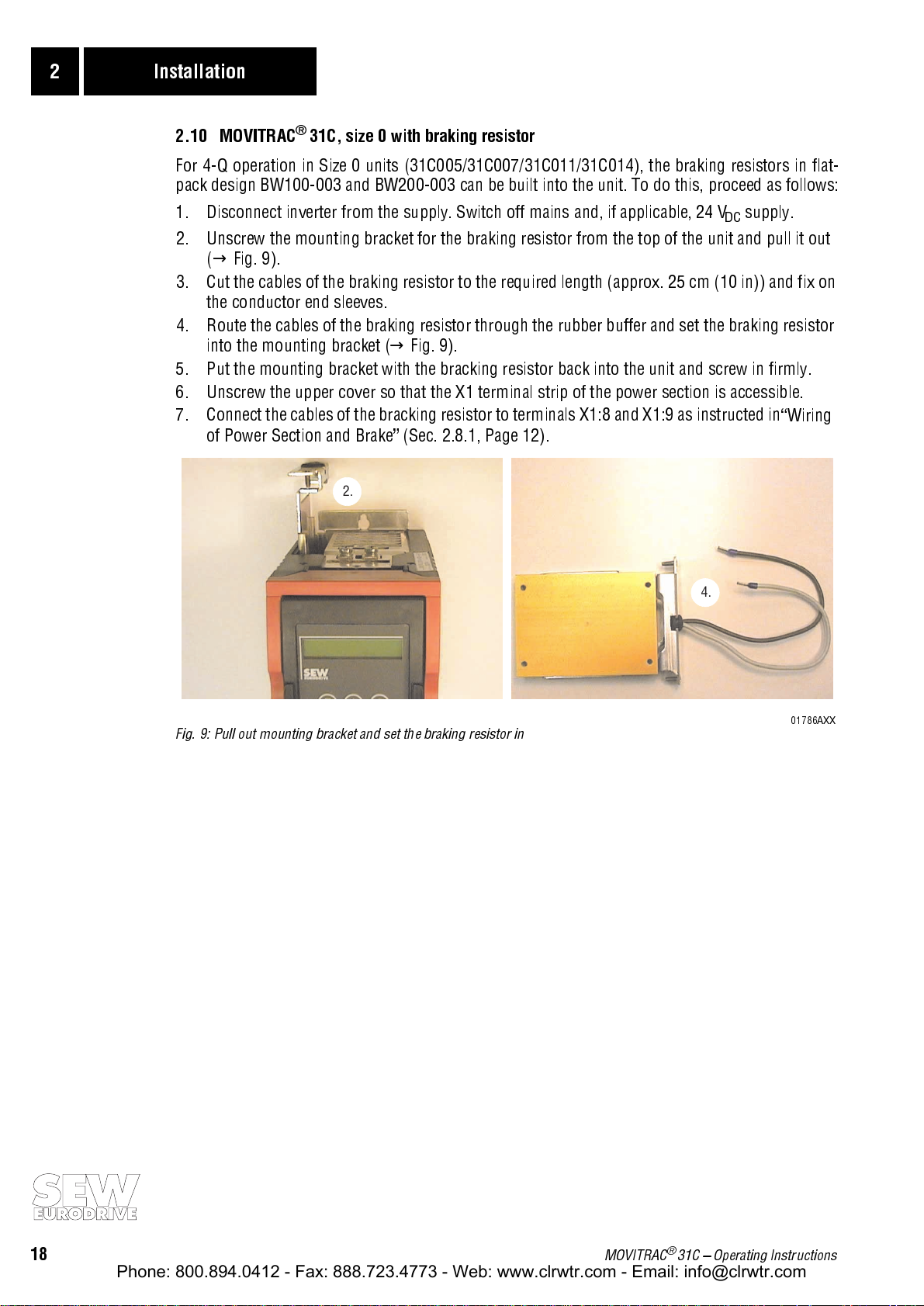
2.10 MOVITRAC® 31C, size 0 with braking resistor
For 4-Q operation in Size 0 units (31C005/31C007/31C011/31C014), the braking resistors in flat-
pack design BW100-003 and BW200-003 can be built into the unit. To do this, proceed as follows:
1. Disconnect inverter from the supply. Switch off mains and, if applicable, 24 V
supply.
DC
2. Unscrew the mounting bracket for the braking resistor from the top of the unit and pull it out
(→ Fig. 9).
3. Cut the cables of the braking resistor to the required length (approx. 25 cm (10 in)) and fix on
the conductor end sleeves.
4. Route the cables of the braking resistor through the rubber buffer and set the braking resistor
into the mounting bracket (→ Fig. 9).
5. Put the mounting bracket with the bracking resistor back into the unit and screw in firmly.
6. Unscrew the upper cover so that the X1 terminal strip of the power section is accessible.
7. Connect the cables of the bracking resistor to terminals X1:8 and X1:9 as instructed in
of Power Section and Brake
2.
(Sec. 2.8.1, Page 12).
4.
Wiring
Fig. 9: Pull out mounting bracket and set the braking resistor in
01786AXX
18
MOVITRAC® 31C Operating Instructions
Page 19
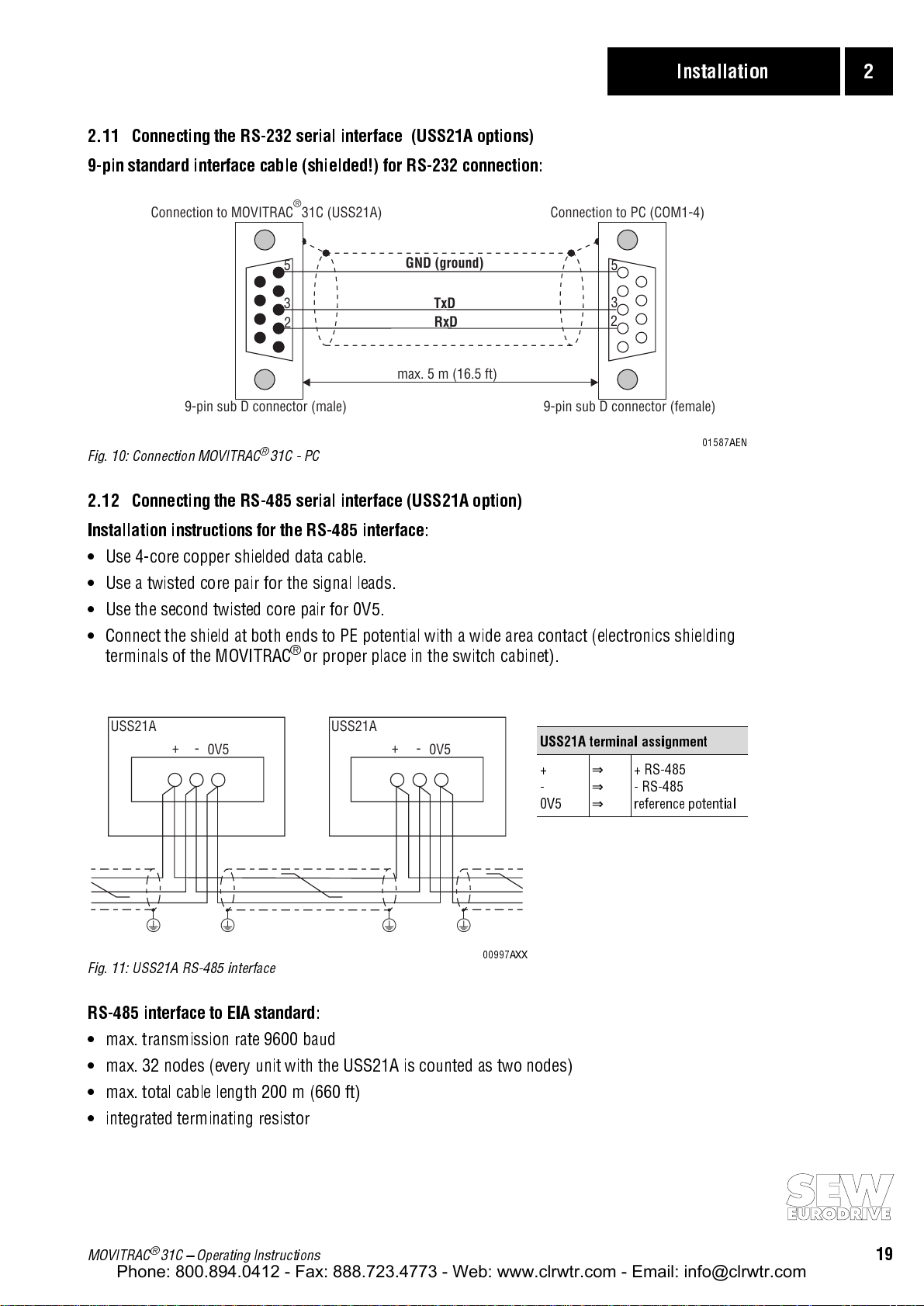
2.11 Connecting the RS-232 serial interface (USS21A options)
Phone: 800.894.0412 - Fax: 888.723.4773 - Web: www.clrwtr.com - Email: info@clrwtr.com
9-pin standard interface cable (shielded!) for RS-232 connection:
Installation 2
®
5
3
2
Fig. 10: Connection MOVITRAC® 31C - PC
GND (ground)
TxD
RxD
max. 5 m (16.5 ft)
Connection to PC (COM1-4)Connection to MOVITRAC 31C (USS21A)
5
3
2
9-pin sub D connector (female)9-pin sub D connector (male)
2.12 Connecting the RS-485 serial interface (USS21A option)
Installation instructions for the RS-485 interface:
Use 4-core copper shielded data cable.
Use a twisted core pair for the signal leads.
Use the second twisted core pair for 0V5.
Connect the shield at both ends to PE potential with a wide area contact (electronics shielding
®
terminals of the MOVITRAC
or proper place in the switch cabinet).
01587AEN
USS21A USS21A
+
-
0V5
yyyy
Fig. 11: USS21A RS-485 interface
+
-
0V5
00997AXX
RS-485 interface to EIA standard:
max. transmission rate 9600 baud
max. 32 nodes (every unit with the USS21A is counted as two nodes)
max. total cable length 200 m (660 ft)
integrated terminating resistor
USS21A terminal assignment
+
-
0V5
⇒
+ RS-485
⇒
- RS-485
⇒
reference potential
MOVITRAC® 31C Operating Instructions
19
Page 20
2 Installation
Phone: 800.894.0412 - Fax: 888.723.4773 - Web: www.clrwtr.com - Email: info@clrwtr.com
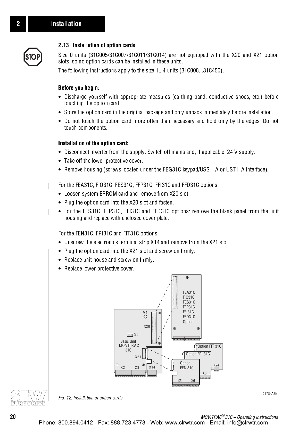
2.13 Installation of option cards
Size 0 units (31C005/31C007/31C011/31C014) are not equipped with the X20 and X21 option
slots, so no option cards can be installed in these units.
The following instructions apply to the size 1...4 units (31C008...31C450).
Before you begin:
Discharge yourself with appropriate measures (earthing band, conductive shoes, etc.) before
touching the option card.
Store the option card in the original package and only unpack immediately before installation.
Do not touch the option card more often than necessary and hold only by the edges. Do not
touch components.
Installation of the option card:
Disconnect inverter from the supply. Switch off mains and, if applicable, 24 V supply.
Take off the lower protective cover.
Remove housing (screws located under the FBG31C keypad/USS11A or UST11A interface).
For the FEA31C, FIO31C, FES31C, FFP31C, FFI31C and FFD31C options:
Loosen system EPROM card and remove from X20 slot.
Plug the option card into the X20 slot and fasten.
For the FES31C, FFP31C, FFI31C and FFD31C options: remove the blank panel from the unit
housing and replace with enclosed cover plate.
For the FEN31C, FPI31C and FIT31C options:
Unscrew the electronics terminal strip X14 and remove from the X21 slot.
Plug the option card into the X21 slot and screw on firmly.
Replace unit house and screw on firmly.
Replace lower protective cover.
FEA31C
FIO31C
FES31C
FFP31C
X7
FFI31C
FFD31C
Option
X7 X8
Option FPI 31C
Option
FEN 31C
X5 X6
X5 X6
Option FIT 31C
X5 X24
X4
Basic Unit
MOVITRAC
31C
X2 X3
V1
X20
X21
X14
Fig. 12: Installation of option cards
20
MOVITRAC® 31C Operating Instructions
01784AEN
Page 21

2.14 Wiring diagram and terminal description for the FEA31C option
Phone: 800.894.0412 - Fax: 888.723.4773 - Web: www.clrwtr.com - Email: info@clrwtr.com
X20:
FEA31C Input/Output Option
*Factorysettings
n13/n23*
1)
Ref.48-51
60
0V24
30
0/1=I *
1/0=No faults/ Ixt-Warning*
63
Ref
RS-485+
RS-485-
64
67
68
1)Jumper,
factoryinstalled
K14
TL.31
TL.31
Shield
X0:
0...10V
X7:
R12
V
0...10V
TL.32-33
+
=
=
-
n1(0...10V)
+-
32
R13
+
V
-
Ext.currentlimit
+-
36
33
TL.36-37
=
Outputcurrent*
Outputfrequency*
0V10
X8:
0
37
38
39
TL.44
V
V
TL.38/39
Analogoutputs
viaD/AConverter
For100%I TL.36 can
max
beconnectedtoTL.31
0/1=Parameterset 1/2*
0/1=n11/n21*
0/1=n12/n22*
0/1=Reset*
48
49
50
51
S15
S16
S17
S18
Binaryoutput signals
forPLCorexternal
outputrelays;max.50mA
(alternativeminiaturecontacts
24V;max. 1,2W)
Installation 2
Fig. 13: FEA31C wiring diagram
Option FEA31C input/output expansion
Part number 822 297 5
Analog differential input X7:32/33 n1 = 0...+10V / -10V...0... +10V
External current limitation X7:36/37 0...10V = 0...100% I
Analog outputs
Signal form
Control functions
X7:38/39 Max. cable length: 10m (33 ft) / Resolution: 8 Bit / Sample time ≤ 10ms
0...±10V, I
→
menu P63_
max
= 3mA
(→ P320)
max
Reference terminal X7:0 Reference potential for analog signals (0V10)
Binary inputs
X8:48/49/50/51 R
≈ 3.0k
i
Ω
PLC compatible according to EN 61131-2
IE ≈ 10mA Sample time: 5ms
Signal level
Control functions
+13V...+30V
-3V...+5V
→
menu P60_
1 opto-isolated
=
=
0
Reference terminal X8:60 Reference for binary inputs X8:48/49/50/51
Reference terminal X8:30 Reference potential for binary signals (0V24)
Binary outputs
Signal level
Control functions
X8:63/64 R
≈ 100
Ω
i
PLC compatible Response time: 5ms
0 = 0V 1 = +24V I
→
menu P61_
max
= 50mA
RS-485 interface X8:6768RS-485+ EIA standard, 9600 baud, max. 32 nodes
RS-485- Integrated terminating resistor
Max. cable length: 200m (660ft)
00513AEN
MOVITRAC® 31C Operating Instructions
21
Page 22

2 Installation
Phone: 800.894.0412 - Fax: 888.723.4773 - Web: www.clrwtr.com - Email: info@clrwtr.com
2.15 Wiring Diagram and Terminal Description for the FIO31C Option
X20:
FIO31C DigitalInput/Output Option
*Factorysettings
1/0=MCready/not ready*
1/0=Rotationfield off*
1/0=Parameterset1/2*
0/1=Nofunction*
0/1=Nofunction*
0/1=Nofunction*
0V24
1/0=Motorwarning1*
0/1=n11/n21*
n13*
0/1=Parameterset1/2*
0/1=n12/n22*
0/1=Reset*
Ref.48-54
0V24
Ref
0/1=I *
1/0=Nofaults /Ixt- Warning*
RS-485+
RS-485-
X19:
Shield
X0:
TL.44
52
S19
53
S20
54
S21
30
69
X8:
72
71
70
48
49
50
51
60
1)
TL.44
S15
S16
S17
S18
Binaryoutput signalsfor PLCor external
outputrelays;max. 50mA(alternative
miniaturecontacts24V;max.1.2 W)
30
63
64
67
68
1)Jumper,
factoryinstalled
K14
Fig. 14: FIO31C wiring diagram
Option FIO31C digital input/output expansion
Part number 822 419 6
Binary inputs
Signal level
Control functions
X8:48/49/50/51
X19:52/53/54
R
≈ 3.0k
Ω
i
PLC compatible according to EN 61131-2
IE ≈ 10mA Sample time: 5ms
+13V...+30V
-3V...+5V
→
Menü P60_
=
1 opto-isolated
0
=
Reference terminal X8:60 Reference for binary inputs X8:48/49/50/51 and X19:52/53/54
Reference terminal X8:30 Reference potential for binary signals (0V24)
Binary outputs
Signal level
Control functions
X19:69/70/71/72
X8:63/64
R
≈ 100
Ω
i
PLC compatible Response time: 5ms
0 = 0V 1 = +24V I
→
menu P61_
max
= 50mA
RS-485 interface X8:6768RS-485+ EIA standard, 9600 baud, max. 32 nodes
RS-485- Integrated terminating resistor
Max. cable length: 200m (660ft)
00576AEN
22
MOVITRAC® 31C Operating Instructions
Page 23

2.16 Wiring diagram and terminal description for the FEN31C/FPI31C option
Phone: 800.894.0412 - Fax: 888.723.4773 - Web: www.clrwtr.com - Email: info@clrwtr.com
X21:
FEN 31C Speed Detection Option or
FPI 31C Position Detection Option
for higher level
control
Installation 2
A
ABBCC
0V10
A
ABBCC
+5V (300mA) Encoder supply
+5V Sensor
0V Sensor
0V Encoder supply
X5: X6:
81
82
83
84
85
86
87
88
89
90
91
92
93
94
95
96
97
Shield
X0:
6
Channel C/ C only
required for output
via TL.X5: 85/86 or IPOS
Encoder 5V TTL
00514AEN
Fig. 15: FEN31C/FPI31C wiring diagram
Option FEN31C speed detection / FPI31C position detection
Part number 822 321 1 / 822 304 1
Pulse outputs
A/A
, B/B, C/C
X5:81...X5:86 +5V, TTL level (RS-422)
Reference terminal X5:87 Reference potential for analog signals (0V10)
Pulse inputs
A/A
, B/B, C/C
Limit speed
X6:88...X6:93 +5V, TTL level (RS-422) f
128/256/512/1024/2048 pulses/revolution (1024 preferred)
12000 min
-1
at 1024 pulses/revolution
= 200 kHz
limit
6000 min-1 at 2048 pulses/revolution
Encoder supply X6:9497+5...8V (Ub / +)
Reference potential (⊥)
Sensor lead X6:9596+5V For voltage measurement and voltage
0V drop compensation on the encoder.
Encoder connection:
Track sequence A → B means CW rotation of the motor facing the motor shaft.
MOVITRAC® 31C Operating Instructions
23
Page 24

2 Installation
Phone: 800.894.0412 - Fax: 888.723.4773 - Web: www.clrwtr.com - Email: info@clrwtr.com
2.17 Wiring diagram and terminal description for the FIT31C option
{
X21:
FIT31C Option TF/TH evaluation
n13*
*Factory setting
0/1 = n11*
0/1 = n12*
0V24
Reference 48/49
X14: X24:
48
49
60
30
Binary input
"EXT. FAULT"
Fig. 16: FIT31C wiring diagram
Option FIT31C TF/TH evaluation
Part number 822 710 1
Binary inputs
Signal level
Control functions
Reference terminal X14:60 Reference for binary inputs X14:48/49
Reference terminal X14:30/X24:30 Reference potential for binary signals (0V24)
TF/TH connection X24:73 Response threshold R
Binary output
Signal level
Control functions
X14:48/49 R
X24:74 R
≈ 3.0k
Ω
i
IE ≈ 10mA Sample time: 5ms
+13V...+30V
-3V...+5V
→
Menü P60_
≈ 100
Ω
i
0 = 0V 1 = +24V I
0 = motor temperature too high or TF/TH lead open circuit
1 = motor temperature within the permissible range
ϑ
TH TF
PLC compatible according to EN 61131-2
1 opto-isolated
=
=
0
PLC compatible Response time: 5ms
0V24
TF/TH Connection
30
73
ϑ
≥ 2.9 kΩ ±10%
TF
Fault output
74
= 50mA
max
01742AEN
X24:74 is connected to a binary input which is programmed to the function "EXT. FAULT".
If X24:74 = "0", the unit will trigger a rapid stop.
MOVITRAC
®
31C meets the requirements for safe and reliable separation of the power and control
sections in accordance with EN 50178. The FIT31C option has the same supply voltage level as the
control board. If a circuit is connected to the control board of the unit which is not safety-separat-
®
ed, then the MOVITRAC
24
31C's protection by electrical separation is no longer given.
MOVITRAC® 31C Operating Instructions
Page 25

2.18 Connecting the incremental encoder
Phone: 800.894.0412 - Fax: 888.723.4773 - Web: www.clrwtr.com - Email: info@clrwtr.com
Installation 2
Detailed information is contained in the
SEW Encoder Systems manual which can be ordered
from SEW under the number 0919 6412.
Max. cable length (inverter - encoder):
100 m (330 ft) at cable capacitance per unit length ≤ 120 nF/km (193 nF/mile)
Core cross-section: 0.20 ... 0.5 mm2 (AWG24 ... AWG20)
Use a shielded cable with twisted-pair conductors and connect shield at both ends (to the elec-
tronics shield clamp and to the encoder connector).
Route the encoder cable separately from the power cables.
Permissible number of increments: 256, 512, 1024, 2048 (preferably 1024)
Apply the shield of the encoder cable over a wide contact surface:
on the inverter on the encoder
Fig. 17: Apply the shield to the electronics
shield clamp of the inverter.
For operation with MOVITRAC
®
31C frequency inverters, SEW recommends using the ES1T, ES2T
01937AXX
Fig. 18: Apply the shield to the PG screw of the encoder.
01948AXX
or EV1T incremental encoders (TTL encoder), previously the IG11 / IG5 encoders. Connect the
encoder as follows:
ES1T / ES2T / EV1T
A (K1)
()
AK1
B (K2)
()
BK2
UB K1 K2K0⊥ K1 K2 K0
UB ABC⊥ ABC
* Connect the sensor leads of the encoder to UB and ⊥, do not jumper on the inverter!
Fig. 19: Connection of the TTL encoder ES1T, ES2T or EV1T to the MOVITRAC® 31C
C (K0)
()
CK0
UB
⊥
yy
max. 100 m (330 ft)
88
89
90
91
92
93
94
95*
96*
97
X6:
MC31C
FEN 31C/
FPI 31C
01585BXX
The K0 (C) and K0 ( C ) tracks are required only for the positionin g control (FPI31 C optio n). They are
not needed for speed control (FRN31C or FEN31C option) or for synchronous operation (FRS31C
option).
MOVITRAC® 31C Operating Instructions
25
Page 26

3 Startup
Phone: 800.894.0412 - Fax: 888.723.4773 - Web: www.clrwtr.com - Email: info@clrwtr.com
3 Startup
Observe the following safety instructions (→ Sec. 1, page 4) during startup!
The prerequisite for a successful startup is the correct project planning of the drive. Detailed
instructions for project planning and the explanation of the parameters are contained in the
MOVITRAC
3.1 Preliminary work and aids
Preliminary work:
Check installation (→ Sec. 2, Installation).
Prevent unintentional start-up of the motor with appropriate measures (e.g. removing the elec-
tronics terminal strip X3). Depending on the application, additional measures must be taken to
ensure that there is no danger to persons or equipment.
When startup with FBG31C keypad:
Plug FBG31C keypad into X4 slot.
When startup with PC and MC_SHELL:
Plug USS11A option into X4 slot and connect with the PC using an interface cable (RS-232). For
this the MOVITRAC
Switch on both units and, if not yet available, install and start MC_SHELL on the PC.
Switch on mains supply and, if applicable, 24V supply. LED (V1) display is yellow.
When using the FBG31C keypad, the following message is displayed for approx. 5 seconds:
®
31C catalog (order no.: 0922 9116).
®
31C and PC must be voltage-free, otherwise undefined states can occur.
SELFTEST
01593AXX
Correct presetting of the parameters (e.g. factory setting). The factory setting of the inverter pro-
vides an activated short menu on the FBG31C keypad which is indicated by the
/ after the para-
meter number.
Check the programmed terminal assignment (→ P60_ / P61_).
For programming IPOS, MC_SHELL is required. The IPOS parameters cannot be edited and
changed with the FBG31C keypad. The IPOS program is stored on the FBG31C when it is saved and
when copying the parameter set onto another MOVITRAC
®
31C it is also copied.
26
MOVITRAC® 31C Operating Instructions
Page 27

3.2 Short-cut startup with the FBG31C keypad
EQ
Phone: 800.894.0412 - Fax: 888.723.4773 - Web: www.clrwtr.com - Email: info@clrwtr.com
3.2.1 Functions of the FBG31C keypad for startup
Detailed information → Sec. 4.1.2
↑
-key: Next menu point or, in editing mode, changes value
(greater).
↓
-key: Previous menu point or, in editing mode, changes value
(smaller).
→
-key: Either one menu level down or changes to editing mode of
the menu point.
←
-key: One menu level up or exits editing mode of the menu point.
Q -key: Returns to basic display.
01406AXX
E -key Reset in case of fault.
3.2.2 Selecting a language on the FBG31C keypad with the short menu
Startup 3
The default language displayed is German.
KEINE
FREIGABE
Press the ↓-key three times.
8 0/ DEUTSCH
P850 (LANGUAGE) is then displayed.
5
SPRACHE
Press the →-key to activate the editing mode. Use the ↓-
or ↑-key to select the language and exit the editing mode
by pressing the ←-key.
850/ ENGLISH _
LANGUAGE
Press the Q-key to return to the default display.
3.2.3 Selecting a language on the FBG31C keypad with the detailed parameter menu
The default language displayed is German.
KEINE
FREIGABE
Press the ↓-key once.
The 8.. parameter group is then displayed.
8.. SONDERFUNKTIONEN
01595ADE
01770ADE
01771AEN
01595ADE
01767ADE
Press the →-key once and the ↑-key five times.
8 . SPRACHEN-
The 85. parameter group (LANGUAGE SWITCHING) is
then displayed.
5
UMSCHALTUNG
Press the →-key to select P850 (LANGUAGE) and press
the →-key again to activate the editing mode. Use the ↓-
or ↑-key to select the language and exit the editing mode
850 ENGLISH _
LANGUAGE
by pressing the ←-key.
Press the Q-key to return to the default display.
MOVITRAC® 31C Operating Instructions
01768ADE
01769AEN
27
Page 28

3 Startup
Phone: 800.894.0412 - Fax: 888.723.4773 - Web: www.clrwtr.com - Email: info@clrwtr.com
3.2.4 Short-cut startup procedure
1. "0"-signal on terminal X3:43 ("Enable/rapid stop"),
e.g. by disconnecting electronics terminal strip X3.
2. Set FMIN1 (P200) = 5 Hz and FBASE1 (P201) and
FMAX1 (P202) as per the motor nameplate data.
3. Return to default display with Q and start the drive with
1 signal on X2:41 ( CW/stop ) or X3:42 ( CCW/
a
stop
The drive runs at a frequency of FMIN1 = 5 Hz.
) and a 1 signal on X3:43 ( Enable/rapid stop ).
NO ENABLE
01595AEN
200/ 5.00HZ
FMIN1
01597AXX
FREQ. 5.00 Hz
CURRT 73%
01772AEN
Important:
The current display relates to the inverter rated current, not to the motor rated current.
If using a motor with rated motor power < recommended motor power rating of the inverter, the
indicated inverter current must be converted to motor current.
Example:
It must also be noted that in this case
Recommended motor power rating inverter = 3 kW, rated motor power = 1.5 kW
→
Display
CURRENT 50% = 100% motor rated current
Motor size-up (P328/P348 = YES ) causes excessive
Boost and I×R, such that excessive motor current is induced.
4. Check direction of rotation of the drive (correct by switching off and exchanging motor phases).
5. If the drive is running properly, the frequency setpoint
can be increased until the required drive frequency is
induced.
FREQ. 30.00 Hz
CURRT 78%
01773AEN
6. Set the ramp generators, e.g. T11 RAMPE UP (P120),
and the frequency characteristics (e.g. FMIN1) as per the
project data.
Important:
If N2 SIGNAL TL.34/35 (P110) is progammed to -10...10V, the fixed setpoints
120/T11 1.00 s
RAMPUP
01598AEN
(P160...P162/P170...P172) cannot be selected.
The function
Motor size-up (P328/P348):
Can be used to adjust the values for BOOST and I×R automatically (P328/P348 = YES). This is use-
ful for single-motor operation with a matched motor (P
the inverter). The values may be changed by manual adjustment. When the
= recommended motor power rating of
Mot
Motor size-up
function is switched on (P328/P348 = YES), BOOST and I×R will be adjusted to the changed opera-
ting conditions (e.g. warmed up motor) at every enable.
Manual setting of BOOST and I×R (P328/P348 = NO):
The values are stored in the non-volatile memory. Set BOOST (P321/P341) and I×R (P322/P342)
with the cold motor. If the setting is carried out with the warm motor the drive may be overcom-
pensated when it is later switched on in cold state, i.e. it may fail to start. In this case, BOOST and
I×R must be reduced as far as is necessary until the drive starts.
Recommendation:
Enter parameter settings, which are not identical with the factory setting, in the parameter list
(→ sec. 3.5).
For information about the starting of the motor, please refer to the notes in sec. 3.3, page 29.
28
MOVITRAC® 31C Operating Instructions
Page 29

Startup 3
Phone: 800.894.0412 - Fax: 888.723.4773 - Web: www.clrwtr.com - Email: info@clrwtr.com
3.3 Starting the motor
Operation with analog setpoint signal
(unipolar, selection of the direction of rotation via terminals):
The following table shows which signals must be present with factory setting (P110 = 0...10 V) at
the terminals X2 and X3 so that the drive is operated with an analog setpoint signal.
X2:41
CW/stop
X3:42
CCW/stop
X3:43
Enable/rapid stop
X2:34
n2
Function
X X "0" X No en a ble
"0" "0" "1" X Stop
"1" "0" "1" 5 V CW operation with 25 Hz
"1" "0" "1" 10 V CW operation with 50 Hz
"0" "1" "1" 5 V CCW operation with 25 Hz
"0" "1" "1" 10 V CCW operation with 50 Hz
The following travel diagram shows exemplarily how the motor is started with an analog setpoint
by applying signals to the terminals X2/X3. The binary output X3:61 ("/Brake") is used to switch the
brake contactor K12.
Input X2:41
CW/stop
Input X3:42
CCW/stop
Input X3:43
Enable/
Rapid stop
Output X3:61
Brake released
Setpoint
input n2
(TL. X2:34)
"1"
"0"
"1"
"0"
"1"
"0"
"1"
"0"
10V
5V
0V
f [Hz]
Output
frequency
A
f
start-stop
50
CW
25
f
min
t11 UP
t11 UP
0
25
CCW
50
t11 UP
t11 DOWN
t11 DOWN
t13 rapid stop ramp
t11 UP
t13 rapid
stop ramp
Fig. 20: Travel diagram with analog setpoints
MOVITRAC® 31C Operating Instructions
01599AEN
29
Page 30

3 Startup
Phone: 800.894.0412 - Fax: 888.723.4773 - Web: www.clrwtr.com - Email: info@clrwtr.com
Operation with fixed setpoints (selection of the direction of rotation via terminals):
The following table shows which signals must be present with factory setting (P110 = 0...10 V) and
installed FEA31C option at the terminals X2/X3/X8 so that the drive is operated with fixed setpoints.
X2:41
CW/stop
X X 0 X X No enable
"0" "0" "1" X X Stop
"1" "0" "1" "1" "0" CW operation with n11
"1" "0" "1" "0" "1" CW operation with n12
"1" "0" "1" "1" "1" CCW operation with n13
"0" "1" "1" "1" "0" CCW operation with n11
X3:42
CCW/stop
X3:43
Enable/rapid stop
X8:48
n11/n21
X8:49
n12/n22
Function
The following travel diagram shows exemplarily how the motor is started with fixed setpoints by
applying signals to the terminals X2/X3/X8. The binary output X3:61 ("/Brake") is used to switch the
brake contactor K12.
Input X2:42
CW/stop
Input X3:42
CCW/stop
Input X3:43
Enable/
Rapid stop
Input X8:48
n11/n21
Input X8:49
n12/n22
Output X3:61
Brake released
Output
frequency
"1"
"0"
"1"
"0"
"1"
"0"
"1"
"0"
"1"
"0"
"1"
"0"
f [Hz]
A
50
25
25
50
CW
5
0
5
CCW
t11 UP
t11 UP
t11 UP
t11 DOWN
t11 UP t13 rapid stop
ramp
Fig. 21: Travel diagram with fixed setpoints
30
MOVITRAC® 31C Operating Instructions
01602AEN
Page 31

Startup 3
Phone: 800.894.0412 - Fax: 888.723.4773 - Web: www.clrwtr.com - Email: info@clrwtr.com
Manual operation:
Manual operation function allows the inverter to be operated manually via the FBG 31C
The
keypad, without external commands over the binary inputs. The input commands are ineffective
during manual operation.
The direction of rotation is not determined by the "CW/Stop" or the "CCW/Stop" input commands,
but rather by selecting the direction with the keypad (→ Fig. 22).
Manual operation remains in effect after power-down and power-up, however, the inverter is not
enabled after power up. A directional command with the [→] or [←] keys results in an enable and
start at f
keys. The rate of change is 150 rpm per second.
in the chosen direction of rotation. Speed is increased and reduced with the [↑] or [↓]
min
87 NO
0
MANUAL OPERATION
←-Key
68 %In 2.00 Hz
Q= HALT CW
Fig. 22: Manual operation with FBG31C
←-Key
870 O
MANUAL OPERATION
E-Key
ROTATING SENSE
CCW E = EXIT CW
→-Key
←-Key
↑-Key: increase speed
↓-Key: decrease speed
→-Key
N
↑↓- or -Key
Q-KeyQ-Key
→-Key
68 %In 2.00 Hz
CCW Q = HALT
01798AEN
MOVITRAC® 31C Operating Instructions
31
Page 32

3 Startup
Phone: 800.894.0412 - Fax: 888.723.4773 - Web: www.clrwtr.com - Email: info@clrwtr.com
3.4 Startup examples
3.4.1 Notes and presettings for the following examples
Notes:
The examples refer to the parameter settings as per the factory setting and parameter set 1.
The terminal designations and functions refer to the wiring diagram for the basic unit
(→ Sec. 2.7, page 11).
Rated motor power P
= recommended motor power rating of the inverter.
Mot
Setpoint n2 (TL. 34/35) is set to V signal unipolar (P110 = 0...10V) by factory.
Alternate settings:
- V signal bipolar (P110 = -10...+10V)
- I signal 0...20 mA (P110 = 0...20mA and S1 switch on I signal = left)
- I signal 4...20mA (P110 = 4...20mA and S1 switch on I signal = left)
Presettings:
0 -signal on all binary inputs and setpoint inputs.
Set P802 Short menu = OFF, the complete parameter menu is available.
Set the ramp generator time P120 t11 Ramp up and P121 t11 Ramp down to the project
data values. Set P120 and P121 to 5...1 s without special requirements (start with the higher
value).
Operation with a matched motor (P
I
Set P320
1 = 150% (factory setting).
max
= recommended motor power rating of the inverter)
Mot
Setting of P324 Pole pair no. 1 of the connected motor:
P324 = 1 for 2-pole motor
P324 = 2 for 4-pole motor (factory setting) etc.
This serves to indicate the correct speed in P004
Speed .
Check P329 Motor voltage 1 (nameplate of the motor) and set it if necessary.
Set P328 Motor size-up 1 = YES (factory setting) when using a matched motor.
< recommended motor power rating of the inverter: set P328 = NO and P321 BOOST
If P
Mot
and P322 I×R must be adjusted manually.
32
Checking the operating behavior:
After adjustment, the motor should have a no-load current of
about 70...80% when cold. If the application requires a high breakaway torque, then a no-load
current of 100% is also permissible for a short time. If the no-load current is too low or the
motor is overcompensated, then this can be corrected with the P321
BOOST 1 and P322
I×R1 settings.
MOVITRAC® 31C Operating Instructions
Page 33

Startup 3
Phone: 800.894.0412 - Fax: 888.723.4773 - Web: www.clrwtr.com - Email: info@clrwtr.com
3.4.2 Example values for BOOST and I×R
If you use an adjusted motor (P
can automatically determine the values for BOOST 1 (P322) and I×R 1 (P322) with P328
out motor 1
= YES (factory setting). The function can result in excessive BOOST and I×R settings
due to interferences, such as too small motor line cross sections or unstable terminal contacts.
The result may be that the inverter will quickly reach the current limit value during acceleration and
the drive not reach the desired speed.
The following tables are an example for those BOOST- und I×R values determined by the "measure
out motor" function when connecting a 4-pole SEW AC motor (IEC and NEMA version). Please note
that these are merely guidelines. The BOOST and I×R values are subject to different influences, e.g.
motor lines and motor windings temperatures.
Prerequisites:
Motor line, 100 m (330 ft) long
Motor lines are multi-core copper wires with PVC insulation
Motor lines and motor windings temperature is approximately 20°C. IF the motor windings tem-
perature is approximately 100°C, the BOOST and I×R values listed below must be increased by
about 30%.
= recommended motor rating of inverter ± 1 type jump), you
Mot
Measure
Data for IEC motors, motor voltage (P329) = 400 V
Star connection, f
Motor type MOVITRAC® 31C...-503 Cross section of motor line [mm2] BOOST [%] I×R [%]
DT71D4 31C005 1.5 101 76
DT80K4 31C005 1.5 56 42
DT80N4 31C007 / 31C008 1.5 50 38
DT90S4 31C011 1.5 49 37
DT90L4 31C014 / 31C015 1.5 42 31
DT100LS4 31C022 1.5 46 35
DT100L4 31C030 1.5 48 29
DV112M4 31C040 1.5 54 40
DV132S4 31C055 1.5 54 30
DV132M4 31C075 2.5 44 25
DV160M4 31C110 6 34 19
DV160L4 31C150 6 36 20
DV180L4 31C220 10 30 17
DV200L4 31C300 16 26 14
DV225S4 31C370 25 23 13
DV225M4 31C450 35 18 10
(P201, P211) = 50 Hz:
base
MOVITRAC® 31C Operating Instructions
33
Page 34

3 Startup
Phone: 800.894.0412 - Fax: 888.723.4773 - Web: www.clrwtr.com - Email: info@clrwtr.com
Star connection, f
Motor type MOVITRAC® 31C...-503 Cross section of motor line [mm2] BOOST [%] I×R [%]
DT71D4 31C005 1.5 37 28
DT80K4 31C007 / 31C008 1.5 27 20
DT80N4 31C011 1.5 26 20
DT90S4 31C014 / 31C015 1.5 26 20
DT90L4 31C022 1.5 28 21
DT100LS4 31C030 1.5 33 20
DT100L4 31C040 1.5 40 30
DV112M4 31C055 1.5 43 24
DV132S4 31C075 2.5 35 20
DV132ML4 31C110 6 23 13
DV160M4 31C150 6 30 17
DV180M4 31C220 10 24 13
DV180L4 31C300 16 20 11
DV200L4 31C370 25 16 9
DV225S4 31C450 35 15 8
(P201, P211) = 87 Hz:
base
Data for NEMA motors, motor voltage (P329) = 460 V
Star connection, f
Motor type MOVITRAC® 31C...-503 Cross section of motor line [AWG] BOOST [%] I×R [%]
DT71D4 31C005 14 87 65
DT80K4 31C005 14 48 36
DT80N4 31C007 / 31C008 14 42 32
DT90S4 31C011 14 39 29
DT90L4 31C014 / 31C015 14 34 26
DT100LS4 31C022 14 37 28
DT100L4 31C030 14 37 22
DV112M4 31C040 12 35 26
DV132S4 31C055 10 31 17
DV132M4 31C075 10 29 16
DV160M4 31C110 8 26 14
DV160L4 31C150 6 21 12
DV180L4 31C220 4 19 11
DV200L4 31C300 3 22 12
DV225S4 31C370 2 20 11
DV225M4 31C450 2 22 12
(P201, P211) = 60 Hz:
base
34
MOVITRAC® 31C Operating Instructions
Page 35

Startup 3
Phone: 800.894.0412 - Fax: 888.723.4773 - Web: www.clrwtr.com - Email: info@clrwtr.com
Double star connection, f
Motor type MOVITRAC® 31C...-503 Cross section of motor line [AWG] BOOST [%] I×R [%]
DT71D4 31C005 14 24 18
DT80K4 31C007 / 31C008 14 17 13
DT80N4 31C011 14 17 13
DT90S4 31C014 / 31C015 14 16 12
DT90L4 31C022 14 18 14
DT100LS4 31C030 14 21 13
DT100L4 31C040 12 20 15
DV112M4 31C055 10 16 9
DV132S4 31C075 10 18 10
DV132ML4 31C110 8 15 9
DV160M4 31C150 6 14 8
DV180M4 31C220 4 12 7
DV180L4 31C300 3 12 6
DV200L4 31C370 2 12 7
DV225S4 31C450 2 13 7
(P201, P211) = 120 Hz:
base
MOVITRAC® 31C Operating Instructions
35
Page 36

3 Startup
Phone: 800.894.0412 - Fax: 888.723.4773 - Web: www.clrwtr.com - Email: info@clrwtr.com
3.4.3 Travel drive, group drive, pump or fan drive
The notes and presettings of sec. 3.4.1 must be observed!
1. Set P200
2. Set P201
3. Operation with a matched motor: set P328
If P
Mot
f
1 = 2...6 Hz.
min
f
1 and P202 f
base
1 as per the project data.
max
Motor size-up 1 = YES and continue at point 12.
< recommended motor power rating of the inverter and in case of group drives with
common load: set P328 = NO and continue at point 4.
Set BOOST (P321/P341) and I×R (P322/P342) with the cold motor.
4. Set P321
Set P322
Set P323
Select P321
5. Enable the drive with a
stop
BOOST 1 = 0%.
I×R = 0%.
Slip 1 = 0 Hz.
BOOST 1 again.
1 signal on TL. 43 Enable/rapid stop and 1 -signal on TL. 41 CW/
or TL. 42 CCW/stop . Check direction of rotation of the drive (correct by switching off
and exchanging motor phases).
→
The inverter produces an output of f
6. Increase P321
7. Increase P322
8. Set P321
BOOST1 to zero.
9. Reduce P322
10. Increase P321
BOOST 1 , until the drive accelerates to f
I×R , until I
is flowing, i.e. 150% IR is displayed.
max
I×R until the current gets out of the current limit (! 150%In).
BOOST 1 again, until the current is 80% IR.
1, the drive remains at rest or runs very slowly.
min
min
and 80% IR is flowing.
11. Remove the enable with a
0 signal on TL. 43 Enable/rapid stop and 0 -signal on TL. 41
CW/stop or TL. 42 CCW/stop .
f
12. Set P200
13. Set P323
Number of
pole pairs
1 (2-pole) 2700 2760 2820 2880 2940 3300 3360 3420 3480 3540
2 (4-pole) 1350 1380 1410 1440 1470 1650 1680 1710 1740 1770
Slip setting s
14. Connect external setpoint inputs (e.g. setpoint potentiometers) to TL. 32/33
FEA31C) or TL. 34/35
1 to the project data value.
min
Slip 1 to the rated slip sN of the motor.
Rated motor speed [rpm]
Rated motor frequency 50 Hz Rated motor frequency 60 Hz
5 Hz 4 Hz 3 Hz 2 Hz 1 Hz 5 Hz 4 Hz 3 Hz 2 Hz 1 Hz
N
n2 (basic unit).
n1 (only with
15. Start up the motor (→ sec. 3.3).
Note:
Set P328
Motor size-up 1 = NO in case of group drives without common load. The steps 7
through 10 are omitted. Set only the BOOST parameter, I×R stays at zero.
For pumps and fans (in 1Q-mode):
Set long Ramp Up and Ramp Down (t11, t21) times (≈ time required for motor to coast to a stand-
still) and bridge TL. X3:43 (
Enable/rapid stop ) with TL. X2:44 (+24V) or program TL. X3:43 to
No function .
36
MOVITRAC® 31C Operating Instructions
Page 37

3.4.4 Hoist drives with and without counterweight
Phone: 800.894.0412 - Fax: 888.723.4773 - Web: www.clrwtr.com - Email: info@clrwtr.com
The notes and presettings of sec. 3.4.1 must be observed!
1. The hoist should be in the lowest position.
2. Allocation:
1 -signal on TL. 41 CW/stop = hoist movement UP
1 -signal on TL. 42 CCW/stop = hoist movement DOWN
Startup 3
3. Hoist with counterweight: P710
Hoist without counterweight: P710
4. Set P326
Caution:
5. Set P200
6. Set P201
7. Set P260
Number of
pole pairs
1 (2-pole) 2700 2760 2820 2880 2940 3300 3360 3420 3480 3540
2 (4-pole) 1350 1380 1410 1440 1470 1650 1680 1710 1740 1770
Slip setting s
Premagnetization time 1 = 200 ms.
If the premagnetization time is too short the hoist could sag during starting.
f
1 = 10 Hz.
min
f
1 = 50 Hz and P202 f
base
Set 1 START/STOP freq. to 1.5×sN (rated slip of the motor).
Rated motor frequency 50 Hz Rated motor frequency 60 Hz
5 Hz 4 Hz 3 Hz 2 Hz 1 Hz 5 Hz 4 Hz 3 Hz 2 Hz 1 Hz
N
8. Operation with a matched motor: set P328
< recomm. motor power rating of the inverter: set P328 = NO and continue at point 9.
If P
Mot
Hoist function 1 = NO
Hoist function 1 = YES
1 = 70 Hz.
max
Rated motor speed [rpm]
Motor size-up 1 = YES and continue at point 13.
Set BOOST (P321/P341) and I×R (P322/P342) with the cold motor.
9. Set P321
Set P322
Set P323
Select P321
BOOST 1 = 100%.
I×R = 0%.
Slip 1 = 0 Hz.
BOOST 1 again.
10. Enable the drive with a
1 signal on TL. 43 Enable/rapid stop and a 1 signal on TL. 41
CW/stop or TL. 42 CCW/stop . Check direction of rotation of the drive (correct by switching
off and exchanging motor phases).
→
The inverter operates at the current limit (I
If the fault signal
11. Reduce P321
OVERCURRENT appears, reduce the BOOST and re-enable the drive.
BOOST 1 , until the drive accelerates to f
12. Remove the enable with
0 -signal on TL. 43 and set P322 I×R to 75% of the BOOST value.
= 140...150%).
N
min
and <100% IN is displayed.
Example: determined BOOST value = 40 % → set I×R = 30%.
f
13. Set P200
14. Set P323
15. Set P510
16. Connect external setpoint inputs (e.g. setpoint potentiometers) to TL. 32/33
FEA31C) or TL. 34/35
1 to the project data value but more than 6 Hz.
min
Slip 1 to the rated slip sN of the motor.
Speed monitoring 1 and P520 Regen. monitoring 1 = YES.
n2 (basic unit).
n1 (only with
17. Start up the motor (→ sec. 3.3) and check the hoisting and lowering functions. If the drive
does not come up to speed (display CURRENT 150%), reduce I×R a bit. At low speeds the
current should be < 150%.
MOVITRAC® 31C Operating Instructions
37
Page 38

3 Startup
Phone: 800.894.0412 - Fax: 888.723.4773 - Web: www.clrwtr.com - Email: info@clrwtr.com
3.4.5 Speed controller FRN31C / FEN31C
The notes and presettings of sec. 3.4.1 must be observed!
1. Check the encoder connection (→ sec. 2.18).
2. Startup without speed control (P770 = V/f mode) as described in sec. 3.4.3.
3. Check direction of motor rotation; important for the assignment of the encoder tracks.
1 signal on TL. 41 and 43 CW/stop : Looking onto B side of the motor→ CCW rotation
(A side = shaft end, B side = fan) Looking onto A side of the motor→ CW rotation
If the sense of direction is wrong, exchange motor phases.
4. Set P260
5. Set P323
Number of
pole pairs
1 (2-pole) 2700 2760 2820 2880 2940 3300 3360 3420 3480 3540
2 (4-pole) 1350 1380 1410 1440 1470 1650 1680 1710 1740 1770
Slip setting s
Important:
6. Setting of P324
Set 1 START/STOP freq. to the project data, e.g. 0.5 Hz.
Slip 1 to the rated slip sN of the motor.
Rated motor speed [rpm]
Rated motor frequency 50 Hz Rated motor frequency 60 Hz
5 Hz 4 Hz 3 Hz 2 Hz 1 Hz 5 Hz 4 Hz 3 Hz 2 Hz 1 Hz
N
It is imperative that P323 is set to the correct value, in all cases ≠ 0.
Pole pair no. 1 of the connected motor:
P324 = 1 for 2-pole motor
P324 = 2 for 4-pole motor (factory setting) etc.
7. Set P510
8. Set P511 and P521
9. Set P770
10. Set P773
11. Set P774
and P322
Speed monitoring 1 and P520 Regen. monitoring 1 = YES.
Response time 1 . Consider acceleration and overload time.
Operation mode = SPEED CONTROL.
Increments (factory setting = 1024).
s×R = YES. The motor is supplied with current for 500 ms and P321 BOOST1
I×R are set. If P774 = NO remains set, then P322 must be set manually.
12. Start up the motor (→ sec. 3.3).
Caution:
If the value of
the drive will accelerate without control up to f
recognized when motor mode speed monitoring 1 (P510 = YES) is enabled
Increments (P773) is too small and/or the number of pole pairs (P324) is too high,
when enabled (TL. 43 = 1 ). A fault is only
max
and
regenerative mode
speed monitoring (P520 = YES). Then a rapid stop is triggered. If P510 and P520 are not activated,
shut off the drive with Mains Off. If a binary input is programmed to
can also be shut off with a
0 signal on the binary input.
/Controller inhibit , the drive
Optimize the speed controller:
1. Set P120
t11 Ramp up and P121 t11 Ramp down to permissible minimum value and start
the drive.
2. Set P772
Controller time constant > 200 ms and increase P771 P gain until the drive
begins to oscillate.
3. Reduce P771 until the drive just stops oscillating. Operate through the speed range.
4. Decrease P772 in steps. Input a setpoint step change;
correct setting is with only 1 or 2 overshoots.
5. P777
P precontrol prevents excessive overshoots. P777 = 0 means P precontrol = OFF.
The higher P777 is set, the higher P778
Setpoint filter should also be set.
38
MOVITRAC® 31C Operating Instructions
Page 39

3.5 Complete parameter list
Phone: 800.894.0412 - Fax: 888.723.4773 - Web: www.clrwtr.com - Email: info@clrwtr.com
Startup 3
All parameters available with the short menu (→ Sec. 4.1.3) are marked with a
/ .
The short menu will be switched on/offf with P802/.
= not available on size 0 (MC31C005/007/011/014)
Par. Name Value range Par. Name Value range
DISPLAY VALUES DISPLAY VALUES
Basic display 06_ Fault memory
/ Frequency / current
00_ Process values
000 Current / frequency 0...200%/0...400 Hz 062 ERROR t-2
001 Temperature -20...+100°C 063 ERROR t-3
002 Actual parameter set 1/2 064 ERROR t-4
003 External I limit TL.36/37 0...100%
004 Speed 0...9999 rpm 070 PD configuration 1PD+par./1PD
01_ Voltages
010 Voltage DC link 0...1000 V 3PD+par./3PD
011 V motor and frequency 0...1000 V / 0...400 Hz 071 Fieldbus type PROFIBUS/INTERBUS/
02_ Currents / power
020 I apparent 0...200% 072 Fieldbus baud rate 0...1500 kbaud
021/ Utilization 0...125% 073 Fieldbus address 0...255
022/ Motor utilization 1 0...200% 074 PO1 setpoint 0000...FFFF
023 Motor utilization 2 0...200% 075 PI1 actual value 0000...FFFF
03_ Status binary inputs
030/ TL. 41/42/43/47 0/1 077 PI2 actual value 0000...FFFF
031/ TL. 48/49 0/1 078 PO3 setpoint 0000...FFFF
TL. 50/51 (with FEA/FIO) 079 PI3 actual value 0000...FFFF
032 TL. 52/53/54 (with FIO) 0/1
04_ Status binary outputs
040 TL. 61/62 0/1
TL. 63/64 (with FEA/FIO)
043 TL. 69/70/71/72 (with FIO) 0/1
05_ Options
050 Option 1 (X20) None/FEA/FFP/FFI/FES/
051 Option 2 (X21) None/Option card 2/
0...400 Hz / 0...200%
FIO
FEN/FPI/FIT
060/ ERROR t-0 Submenu for
061 ERROR t-1
07_ Fieldbus monitor (only with FFP, FFI or FFD option)
076 PO2 setpoint 0000...FFFF
faults 0...4:
Meas. values at time:
/heat sink temp./
V
DC_link
I
/I×t/terminals/
app
par. set/motor utilization
2PD+par./2PD
DeviceNet
hex
hex
hex
hex
hex
hex
MOVITRAC® 31C Operating Instructions
39
Page 40

3 Startup
Phone: 800.894.0412 - Fax: 888.723.4773 - Web: www.clrwtr.com - Email: info@clrwtr.com
Par. Name Setting range
Factory setting
Switchable par.
Parameter set 1
1__ SETPOINTS / RAMP GENERATORS
10_ Setpoint n1 terminal 32/33 (only with FEA)
100
n1 characteristic
101 n1 gain factor 0.1...1...10
102 n1 offset factor 0.1...1...9
11_ Setpoint n2 terminal 34/35 (basic unit)
110/ n2 signal TL. 34/35
(S1 to be noted!)
111 Setpoint offset -500...0...500 mV
12_ 1st ramp generator
120/ t11 ramp up 0.0...1...2000 s 123 t21 ramp up 0.0...1...2000 s
121/ t11 ramp down 0.0...1...2000 s 124 t21 ramp down 0.0...1...2000 s
122 t11 S-pattern
13_ 2nd ramp generator
130/ t12 ramp up = down 0.0...5...2000 s 131 t22 ramp up = down 0.0...5...2000 s
14_ Rapid stop ramp
140/ t13 ramp stop 0.0...1...9.95 141 t23 ramp stop 0.0...1...9.95
15_ Motorized potentiometer
150 Motorized pot. Yes/
151 t4 Ramp up 1...10...60 s
152 t4 Ramp down 1...10...60 s
153 Save last position Yes/
154 Motor pot + setpointNo/sum
16_ 1st set fixed setpoints 17_ 2nd set fixed setpoints
160/ n11 0...5...400 Hz 170 n21 0...5...400 Hz
161/ n12 0...25...400 Hz 171 n22 0...25...400 Hz
162/ n13 0...50...400 Hz 172 n23 0...50...400 Hz
163 Mix 1st set + n1
18_ Setpoint hold function
180 Setp. hold function 1
181 Stop setpoint 1 0...2...25 Hz / ... mV 184 Stop setpoint 2 0...2...25 Hz / ... mV
182 Start hysteresis 1 0.1...2...5 Hz / ... mV 185 Start hysteresis 2 0.1...2...5 Hz / ... mV
19_ Terminal control mode
190
Control mode
Gain
/offset
0...10 V
0...20mA / 4...20mA
0
No
product
Yes
STANDARD
3-WIRE-CTRL
/ -10..10V /
/1/2/3 125 t21 S-pattern
no
no
/sum/
/no 183 Setp. hold function 2
/
After start- upPar. Name Setting range
Factory setting
Parameter set 2
0
/1/2/3
173 Mix 2nd set + n1
No
/sum/
product
Yes
/no
After start-
up
40
MOVITRAC® 31C Operating Instructions
Page 41

Startup 3
Phone: 800.894.0412 - Fax: 888.723.4773 - Web: www.clrwtr.com - Email: info@clrwtr.com
Par. Name Setting range
Factory setting
After start- upPar. Name Setting range
Factory setting
Switchable par.
Parameter set 1 Parameter set 2
2__ FREQUENCY CHARACTERISTICS
20_ Stepwise V/f pattern 1 21_ Stepwise V/f pattern 2
200/ f
201/ f
202/ f
1 0...2...40 Hz 210 f
min
1 stepwise
base
1 5...50...150 Hz 212 f
max
50
/60/87/104/120 Hz 211 f
2 0...2...40 Hz
min
2 stepwise
base
2 5...50...150 Hz
max
50
/60/87/104/120 Hz
22_ Stepless V/f pattern 3
220 f
221 f
222 f
3 0...2...150 Hz
min
3 stepless 5...50...400 Hz
base
3 5...50...400 Hz
max
23_ 1st frequency window skip
230 1st freq. window Yes/
no
231 Window centre 5...50...150 Hz
232 Window width ± 2...9 Hz
25_ Selection V/f pattern
250 V/F pattern
Parameter set 1
1
/3 251 V/F pattern
Parameter set 2
2
/3
26_ START/STOP frequency
260/ Set 1 START/STOP
frequency
0...2...10 Hz 261 Set 2 START/STOP
frequency
0...2...10 Hz
3__ MOTOR PARAMETERS
31_ Manual adjustment 1/1 33_ Manual adjustment 2/1
310 Motor rated curr. 1 20...90...200% 330 Motor rated curr. 2 20...90...200%
311 PWM fix 1 Yes/
no
331 PWM fix 2 Yes/
no
32_ Manual adjustment 1/2 34_ Manual adjustment 2/2
320/ I
321/ BOOST 1
322/ I×R 1
323/ Slip 1
1 20...
max
150
% 340 I
0
...100% 341 BOOST 2
0
...100% 342 I×R 2
0
...10 Hz 343 Slip 2
2 20...
max
0
...100%
0
...100%
0
...10 Hz
150
%
324 Pole pair number 1 1/2/3/4/5/6 344 Pole pair number 2 1/2/3/4/5/6
325/ PWM frequency 14/8/12/16 kHz 345 PWM frequency 24/8/12/16 kHz
326/ Premagnet. time 1 0...
327 Postmagnet. time 1 0...
328/ Motor size up 1
329/ Motor voltage 1 200...
100
...300 ms 346 Premagnet. time 2 0...
100
...300 ms 347 Postmagnet. time 2 0...
Yes
/no 348 Motor size up 2
400
...600 V 349 Motor voltage 2 200...
Yes
100
100
/no
400
...300 ms
...300 ms
...600 V
35_ Parameter switch over
350 Enable parameter
Yes/
no
switchover
After start-
up
MOVITRAC® 31C Operating Instructions
41
Page 42

3 Startup
Phone: 800.894.0412 - Fax: 888.723.4773 - Web: www.clrwtr.com - Email: info@clrwtr.com
Par. Name Setting range
After start- upPar. Name Setting range
Factory setting
Switchable par.
Parameter set 1 Parameter set 2
4__ REFERENCE SIGNALS
40_ 1st frequency reference values
400 1st frequency ref. 2...50...150 Hz
401 1st hysteresis 1...2...9 Hz
402 1st delay
403 1st signal = 1 at f > f
0
...9 s
Ref
1 /
f < f
Ref
1
41_ 2nd frequency reference values
410 2nd frequency ref. 2...50...150 Hz
411 2nd hysteresis 1. ..2...9 Hz
412 2nd delay
413 2nd signal = 1 at f > f
0
...9 s
Ref
2 /
f < f
Ref
2
43_ Setpoint/actual value comparison
430 Hysteresis ± 1...2...9 Hz
431 Signal = 1 at
Actual = setp.
/
actual <> setp.
45_ 1st current reference value
450 1st current reference10...
100
...150%
451 1st hysteresis ± 1...9%
452 1st delay
453 1st signal = 1 at I < I
0
...9 s
Ref
1 /
I > I
Ref
1
46_ 2nd current reference value
460 2nd current reference10...
100
...150%
461 2nd hysteresis ± 1...9%
462 2nd delay
463 2nd signal = 1 at I < I
47_ I
max
signal
470 Signal = 1 at I = I
471 Delay
0
...9 s
0
...9 s
Ref
max
2 /
/
I > I
I < I
Ref
max
2
Factory setting
After start-
up
42
MOVITRAC® 31C Operating Instructions
Page 43

Startup 3
Phone: 800.894.0412 - Fax: 888.723.4773 - Web: www.clrwtr.com - Email: info@clrwtr.com
Par. Name Setting range
Factory setting
Switchable par.
Parameter set 1 Parameter set 2
5__ MONITORING FUNCTIONS
Deceleration monitoring
50_
500 Decel. monitoring Yes/
501 f
51_ Motor mode speed monitoring
510 Motor mode
511 Response time 1 0.1...1...9 s 513 Response time 2 0.1...1...9 s
52_ Regenerative mode speed monitoring
520 Regenerative mode
521 Response time 1 0.1...1...9 s 523 Response time 2 0.1...1...9 s
53_ Power supply monitoring
530 Mains volt. monitor.
54_ Motor monitoring
541 Motor protection 1
542 Cooling type 1
55_ Synchronous operation monitoring (only with FRS)
550 FRS alert
551 FRS lag error 100...
552 Hold time
553 Fault response
554 Pos. tolerance slave 10...25...32 768
555 LED counter V11 10...
556 Time constant
557 Cable break
56_ Fieldbus PD description
560 Setpoint descr. PO1
561 Act. value descr. PI1
562 Setpoint descr. PO2
563 Act. value descr. PI2
564 Setpoint descr. PO3
565 Act. value descr. PI3
57_ Fieldbus parameters
570 Setpoint enable
571 Fieldbus timeout 0.01...
572 Timeout response
573 CAN sync. ID 0...1...2047
574 DeviceNet PD config 1 PD + PARAM / 1 PD
3
Ref
speed monitoring 1
speed monitoring 1
position signal
master-slave
no
10
...99 Hz
Yes/
no
Yes/
no
Yes
/no
Off
/warning/
switch off
Fan cooled
forced cooled
50
...99 999 999
99 999 999
1
...99 s
0/1-signal
stop/rapid stop
5...10...2000 ms
Yes
Control word 1
Status word 1
Speed
Speed
No function
No function
Yes
Rapid stop + warn.
2 PD + PARAM / 2 PD
3 PD + PARAM / 3 PD
4000
100
/no
/no
0.5
/
...
/coast/
...32 768
...650 s
After start- upPar. Name Setting range
Factory setting
512 Motor mode
speed monitoring 2
522 Regenerative mode
speed monitoring 2
543 Motor protection 2
544 Cooling type 2
Yes/
no
Yes/
no
Off
/warning/
switch off
Fan cooled
forced cooled
After start-
up
/
MOVITRAC® 31C Operating Instructions
43
Page 44

3 Startup
Phone: 800.894.0412 - Fax: 888.723.4773 - Web: www.clrwtr.com - Email: info@clrwtr.com
Par. Name Setting range
Factory setting
Switchable par.
Parameter set 1 Parameter set 2
6__ TERMINAL ASSIGNMENT
60_ Binary inputs 42-54
- Basic unit TL. 41 fixed assigned to:
600 Basic unit TL. 42
601 Basic unit TL 43
602 Basic unit TL 47
603 Basic unit TL 48
604 Basic unit TL 49
605 With FEA/FIO TL. 50
606 With FEA/FIO TL. 51
607 With FIO TL. 52
608 With FIO TL. 53
609 With FIO TL. 54
61_ Binary outputs 62-64, 69-72
- Basic unit TL. 61 fixed assigned to:
611 Basic unit TL. 62
612 With FEA/FIO TL. 63I×
613 With FEA/FIO TL. 64
614 With FIO TL. 69
615 With FIO TL. 70
616 With FIO TL. 71
617 With FIO TL. 72
63_ Analog outputs 38, 39, 65
630 Analog output 1
(TL. 38 only with FEA)
631 Factor output 1 0.1...1...3
632 Analog output 2
(TL. 39 only with FEA)
633 Factor output 1 0.1...1...3
634 Meas. output
(TL. 65 basic unit)
635 Factor meas. output 0.1...1...3
64_ Analog inputs 32-33, 36-37 (only with FEA)
640 Analog input 32/33
(only with FEA)
641 Analog input 36/37
(only with FEA)
CCW/stop
Enable
Ramp switch t2/t1
n11 (n21)
n12 (n22)
Param. switch
Reset
No function
No function
No function
/fault
t warning
1st I reference
No function
No function
No function
No function
Actual frequency
Apparent I
Actual frequency
Setpoint n1
no function
No function
ext. I limit
/
/
After start- upPar. Name Setting range
CW/stop
The following functions can be programmed:
No function CW/stop CCW/stop
Enable Param. switch n11(n21) n12(n22)
M pot up. M pot down. /dec. monitor
Reset
Ramp switch t2/t1 /MC inhibit. /ext. fault
FRS zero pt. FRS control SLAVE start
SLAVE free run.
/limit switch CCW Refer. cam Ref. search FRS teach in
Fix. setpt. sw Setpoint active Pattern
/brake
The following signals can be programmed:
No function MC ready Rotating on
Rotating off Brake applied Manual operation
Parameter set
2nd f reference Actual=setp. 1st I reference
2nd I reference I max /fault decel. /fault
/fault ext.
f-resonance /prewarn.FRS /regen. FRS
Slave in pos. /fault BRC Brake released
Zero speed
At position Output IPOS 1 Output IPOS 2
Output IPOS 3 Output IPOS 4 Output IPOS 5
Output IPOS 6
P. ZERO DEF.
The following functions can be programmed:
Actual frequency Actual speed Ramp gen.
V motor I×t value Apparent I Setp. frequency
After start-
Factory setting
/hold ctrl. /limit switch CW
I×t warning 1st f reference
/current >> DC-link >> /I×t >> /temp. >>
Motor warn.1 Motor warn.2
Output IPOS 7 Output IPOS 8
up
44
MOVITRAC® 31C Operating Instructions
Page 45

Startup 3
Phone: 800.894.0412 - Fax: 888.723.4773 - Web: www.clrwtr.com - Email: info@clrwtr.com
Par. Name Setting range
Factory setting
Switchable par.
Parameter set 1 Parameter set 2
7__ CONTROL FUNCTIONS
71_ Hoist function
710/ Hoist function 1 Yes/
72_ Rapid start function
720 Rapid start 1 Yes/
721 Field current 1 10...35...50% 724 Field current 2 10...35...50%
722 Duration 1
73_ DC braking
730 DC braking 1 Yes/
731 DC brake time 1 0.1...3...30 s 734 DC brake time 2 0.1...3...30 s
732 DC hold current 1 0...25...50% 735 DC hold current 2 0...25...50%
74_ Heating current
740 DC heat current 1 Yes/
741 DC heat current 10...50% 743 DC heat current 20...50%
76_ Synchronous operation
760 Synchronous operat.Yes/
761 MOVITRAC is
762 Master gear ratio fact.1...3 999 999 999
763 Slave gear ratio fact.1...3 999 999 999
764 Mode selection
765 Slave counter -99 999 999...10...
766 Offset 1 -32 767...10...32 767
767 Offset 2 -32 767...10...32 767
768 Offset 3 -32 767...10...32 767
769 Controller KP factor 1...10...200
77_ Speed control
770 Operation mode
771 P gain 0.1...2...60
772 Time constant 1...30...500 ms
773 Increments 128/256/512/
774 S×R Yes/
777 P precontrol
778 Setpoint filter 0...5...100 ms
779 P gain hold control0...60
no
no
3
...180 s 725 Duration 2
no
no
no
Master
/slave
1
...8
99 999 999
V/f control
speed control/
positioning
1024
0
...60
/
/2048
no
After start- upPar. Name Setting range
Factory setting
712 Hoist function 2 Yes/
723 Rapid start 2 Yes/
733 DC braking 2 Yes/
742 DC heat current 2 Yes/
Synchronous operation only in parameter set 1.
Speed control and positioning only in parameter set 1.
3
...180 s
no
no
no
no
After start-
up
MOVITRAC® 31C Operating Instructions
45
Page 46

3 Startup
Phone: 800.894.0412 - Fax: 888.723.4773 - Web: www.clrwtr.com - Email: info@clrwtr.com
Par. Name Setting range
Factory setting
Switchable par.
Parameter set 1 Parameter set 2
8__ SPECIAL FUNCTIONS
80_ Parameter menu
800/ Parameter lock Yes/
801 Save
802/ Short menu
81_ Service informations
810 EPROM syst em 822 XXX X.XX
811 EPROM operation 821 XXX X.XX
812 EPROM fieldbus 821 XXX X.XX
813 Service phone 0171-7210791
82_ Parameter copying
820 Copy from
822 Copy Yes/
83_ Factory setting
830/ Factory setting Yes/
831/ Selection
84_ Mode interfaces
841 Control mode
842 Address inverter
843 Response time
85_ Language switching
850/ Language
86_ Reset mode
860 Auto reset mode Yes/
861 Restart time
862/ Pushbutton reset Yes/
87_ Manual operation
870 Manual operation Yes/
88_ Master-slave operation
880 Master-save Yes/
881 MOVITRAC is MASTER/
882 Weighting factor 0.1...1...10
89_ 4-quadrant operation
890/ 4-quadrant 1
no
On
/off
On
/off Only with FBG31C keypad.
MOVITRAC
STANDARD
BRASIL
Standard
Remote-setp./
Remote-CTRL/
Fieldbus
0
...63
0
...300 ms Only with MC_SHELL and using the RS-485 interface.
DEUTSCH
FRANCAIS
3
...30 s
Yes
/EEPROM
no
no
/U.S.A./
/
/ENGLISH/
no
no
no
no
SLAVE
/no 891 4-quadrant 2
After start- upPar. Name Setting range
Read-only parameters.
In size 0 it is not possible to select "BRASIL".
Factory setting
Yes
/no
After start-
up
46
MOVITRAC® 31C Operating Instructions
Page 47

4 Operation and Service
MC. INHIBITED
NO ENABLE
NO ENABLE
FREQ. 30.00 Hz
CURRT 78%
WARNING XX
FAILURE XX
XXXXXXXXXXXXXXXX
Phone: 800.894.0412 - Fax: 888.723.4773 - Web: www.clrwtr.com - Email: info@clrwtr.com
4.1 Operating displays
4.1.1 LED display
LED V1 colour Note / Explanation
yellow
green
red
yellow flashing
red-yellow flashing
red-green flashing
4.1.2 FBG31C keypad
Basic displays:
Mains voltage is available, inverter is ready for operation.
Rotating field ON
Collective fault signal
Self-test phase (duration max. 5 s) / factory setting (P830 = YES) running / fallen below permis-
sible mains voltage range / external voltage (+24 V on TL.40) and no mains voltage
Limit switch active
Hold control active (IPOS)
Operation and Service 4
01795AEN
01595AEN
01595AEN
01773AEN
01781AEN
01782AEN
Display if mains OFF and 24 VDC external voltage or binary input
/MC. INHIBITED = "0".
Display if X3:43 ("Enable/rapid stop") = "0".
Display if X2:41 ("CW/stop")
Display with inverter enabled.
Coded displays
Fault display
and
X3:42 ( CCW/stop ) = "0".
MOVITRAC® 31C Operating Instructions
47
Page 48

4 Operation and Service
Phone: 800.894.0412 - Fax: 888.723.4773 - Web: www.clrwtr.com - Email: info@clrwtr.com
Functions:
The FBG31C keypad allows complete parameter sets to be copied from one MOVITRAC
into other MOVITRAC
to the keypad with P820
onto another MOVITRAC
with P820
removed and plugged in during operation.
If there is no connection between the inverter and the FBG31C keypad after switching on the mains
and the 24 V supply and plugging in the FBG31C, the fault message COMMUNIC. ERROR NO
SERIAL LINK is displayed. Try to establish communication by plugging in the keypad repeatedly.
Selectable via menu:
_
0.. DISPLAY
VALUES
1.. SETPOINTS/
RAMP GEN.
2.. FREQUENCY
CHARACTERISTICS
3.. MOTOR
PARAMETERS
4.. REFERENCE
SIGNALS
5.. MONITORING
FUNCTIONS
6.. TERMINAL
ASSIGNMENT
7.. CONTROL
FUNCTIONS
8.. SPECIAL
FUNCTIONS
COPY FROM = EEPROM and P822 COPY = YES. The FBG31C keypad can be
1st Menu level
Main menu
[]↓
[]↑
NO ENABLE
®
®
31C units. To do this, upload the parameter set from the MOVITRAC® 31C
31C unit
COPY FROM = MOVITRAC and P822 COPY = YES . Plug the keypad
®
31C unit and download the parameter set into the MOVITRAC® 31C
2nd Menu level
[]→
[]←
Submenu
[]↓
[]↑
1 . SETPOINT N1
0
TERMINAL
1 . SETPOINT N2
1
TERMINAL 34/35
1 .
2
1. RAMP GENERATOR
1 .
3
2. RAMP GENERATOR
1 . RAPID STOP
4
RAMP
1 . MOTOR
5
POTENTIOMETER
1 . 1. SET
6
FIXED SETPOINTS
1 . 1. SET
7
FIXED SETPOINTS
1 . SETPOINT
8
HOLD FUNCTION
32/33
[]→
[]←
11 N2 0 . . . 10 V
0
SIGNAL TL 34/45
11 0 mV
1 111 _0 mV
SETPOINT OFFSET
3rd Menu level
Parameters
[]↓
[]↑
[]→
SETPOINT OFFSET
[]←
Editing mode
Fig. 23: Menu structure
[←] [→] Change menu level, enter ([→]) or exit ([←]) editing mode in 3. menu level
(parameter). The parameter can only be changed in the editing mode.
[↑] [↓] Selection of the menu item, in editing mode value either greater or smaller. By
releasing the [↑]- resp. [↓]-key, the new value becomes effective in the editing mode.
[Q] Return to the basic display or, in P870
MANUAL OPERATION = YES ,
STOP command.
[E] Manual operation: Exit manual operation
In case of fault: Reset-parameter P862 is displayed and allows for clearing a fault.
48
MOVITRAC® 31C Operating Instructions
01783AEN
Page 49

Operation and Service 4
Phone: 800.894.0412 - Fax: 888.723.4773 - Web: www.clrwtr.com - Email: info@clrwtr.com
4.1.3 FBG31C short menu
The FBG31C keypad provides a compehensive parameter menu as well as a clearly arranged short
menu, which contains the most-used parameters. The parameter P802
switching between the two different parameter menus. At the initial start-up of the
MOVITRAC
marked with a
short menu are marked with a
®
31C the short menu is active. When the short menu ist active, all parameters are
/ . In the complete parameter list (→ sec. 8.5) all parameters available with the
/ as well.
[]↑ []↓
Basic display
Frequency
Current
021 / 0..125 %
022 / 0..200 %
030 / 41:1 42:1
031 / 48:1 49:1
060 / Error t-0
Utilization
Motor utilization
43:1 47:0 0/1
50:1 51:0 0/1
SHORT MENU allows for
0..400 Hz
0..200 %
No fault
11_ Setpoint n2
12_ Ramp 1
13_ Ramp 2
14_ Rapid stop
16_ Fixed setpoints
20_ V/f pattern 1
26_ Start/stop freq.
32_ Motor adjustment
110 / 0..10 V
120 / 0,0.. ..2000 s1
121 / 0,0.. ..2000 s1
130 / 0,0.. ..2000 s5
140 / 0,0.. ..9,95 s1,0
160 / n 11 0.. ..400 Hz5
161 / n 12 0.. ..400 Hz25
162 / n 13 0.. ..400 Hz50
200 / f min 1 0.. ..40 Hz2
201 / 50/60/87/104/120 Hz
202 / f max 1 5.. ..150 Hz50
260 / 0.. ..10 Hz2
320 / I max 1 20.. %150
321 / BOOST 1 0..100 %
322 / I x R 1 0..100 %
323 / 0..10 Hz
325 /
326 /
328 /
329 / 200.. ..600 V400
n-signal TL. 34/45
t11 ramp up
t11 ramp down
t12 ramp up = down
t13 ramp stop
f base 1
Start/stop frequency
Slip 1
PWM frequency 1
Premagnetization time 1
Motor size-up 1 Yes / No
Motor voltage 1
4/8/12/16 kHz
0... ...300 ms100
71_ Hoist function
80_ Special functions
710 /
800 /
802 /
830 /
831 /
850 / DEUTSCH/ENGLISH/FRANCAIS
862 /
890 /
Hoist function 1 Yes / No
Parameter lock Yes / No
User menu On / Off
Factory setting
Selection
Language
Pushbutton reset Yes / No
4-quadrant mode Yes / No
Yes / No
STANDARD/USA/BRASIL
Fig. 24: FBG31C Short menu
MOVITRAC® 31C Operating Instructions
00508AEN
49
Page 50

4 Operation and Service
Phone: 800.894.0412 - Fax: 888.723.4773 - Web: www.clrwtr.com - Email: info@clrwtr.com
4.1.4 MOVITRAC® 31C coded displays
During operation, the following messages may appear on the FBG31C (for about 2 s) or on the PC
(resettable message):
Display Meaning
16
17
18
19
20
21
22
23
24
25
27
28
34
35
38
39
41
42
44
45
46
47
48
49
50
51
53
54
*) This message does not appear if the SEW user software is installed. If necessary call the SEW Electronics Service.
Illegal index.*
Function/parameter has not been implemented.*
Read-only parameter.
Parameter lock (P800 = YES) active.
Factory setting (P830 = YES) is running.
Value is too large for this parameter.
Value is too small for this parameter.
Option required for the function or parameter selected is not installed.
Fault system software.
Access to selected parameter is prohibited via this serial interface.
Unauthorized access.*
Access to the selected parameter is only possible when the inverter is inhibited.
→
Set TL. 43 =
Hoist function set 1 (P710) can only be selected in 4-Q operation.
→
Activate 4-Q operation 1 (P890 = YES).
Hoist function set 2 (P712) can only be selected in 4-Q operation.
→
Activate 4-Q operation 2 (P891 = YES).
Hoist function set 1 (P710) only in 4-Q operation.
→
4-Q operation 1 (P890) may not be switched off.
Hoist function set 2 (P712) only in 4-Q operation.
→
4-Q operation 2 (P891) may not be switched off.
Parameter access is only possible via X4 (with FBG31C/USS11A/UST11A) when
- manual operation is activated (P870 = YES)
- or the master-slave function is activated (P880 = JA).
Activate speed control (P770 = speed control).
Motor size up 1 (P328) and Rapid start 1 (P720) cannot be activated simultaneously.
Motor size up 2 (P348) and Rapid start 2 (P723) cannot be activated simultaneously.
Option required (FEA31C/FIO31C) is not installed.
4-Q operation 1 (P890) and DC braking 1 (P730) cannot be activated simultaneously.
4-Q operation 2 (P891) and DC braking 2 (P733) cannot be activated simultaneously.
Controller inhibit active, function can only be activated if mains voltage is applied.
Synchronous operation (P760 = YES) must first be activated.
Syncronous operation SLAVE (P761) is still activated, no change possible..
3-WIRE-CTRL is active, REMOTE-CTRL cannot be activated.
REMOTE-CTRL is active, 3-WIRE-CTRL cannot be activated.
)
)
)
0 or direction of rotation command = 0 .
50
MOVITRAC® 31C Operating Instructions
Page 51

Operation and Service 4
Phone: 800.894.0412 - Fax: 888.723.4773 - Web: www.clrwtr.com - Email: info@clrwtr.com
4.2 Fault information
If a fault occurs, the red LED V1 lights up. Detailed fault indication is given on the FBG31C keypad
or on the PC with MC_SHELL. The fault memory (P060...P064) stores the most recent five fault
signals (fault t-0...t-4) non-volatile. If more than five fault signals are generated, the oldest signal is
deleted. The following data are stored when a fault occurs:
DC link voltage
quency
Two responses are possible depending on the fault type; the inverter remains disabled in fault
mode:
Parameter set 1/2 Apparent current Motor utilization.
Immediate switch-off:
The inverter can no longer accelerate the motor, the output stage is disabled in case of a fault
and the brake is applied (X3:61
Rapid stop:
In this case the motor is decelerated using the rapid stop ram p t13/t23. When reaching the stop
frequency the output stage becomes high-resistant and the brake is applied (X3:61
I×t (utilization) Heat sink temperature Status of the binary inputs/outputs Fre-
/Brake = 0 ).
/Brake = 0 ).
RESET:
A fault signal can be reset by:
Power-down and power-up.
Recommendation: for the mains contactor K11 a minimum power-down time of 10 s should be
considered.
Reset via input terminals, i.e. by a binary input assigned with the function Reset (P60_).
Manual reset in MC_SHELL (P862 = Yes or menu item [Parameter] / [Manual Reset])
Manual reset with FBG31C (Press the <E> key in case of a fault to change to parameter P862)
Auto Reset executes max. three restart attempts with a settable restart time. Not recommended
for drives where automatic restarting may result in injury to people and damage to property.
MOVITRAC® 31C Operating Instructions
51
Page 52

4 Operation and Service
Phone: 800.894.0412 - Fax: 888.723.4773 - Web: www.clrwtr.com - Email: info@clrwtr.com
4.3 Fault signals
A fault is reset with RESET (→ sec. 4.2).
No. Description Response Possible cause Measure
1 Overcurrent Immediate
2 DC link voltage Immediate
3 Brake chopper Immediate
4 Cont. overload Imm. sw. off I×t utilization too high (> 125%). Reduce load.
5 Regenerative
overload
6 Over-
temperature
7 Phase failure Immediate
10 Direction of
rotation
11 Speed
detection
12 Mot. overload Immediate
13 Starting
conditions
14 Output open Immediate
Short circuit/earth fault at the output.
switch-off
switch-off
switch-off
Immediate
switch-off
Rapid stop Thermal overload of the inverter. Reduce load and / or ensure adequate
switch-off
Immediate
switch-off
Immediate
switch-off
switch-off
Immediate
switch-off
switch-off
Motor too large.
Faulty output stage.
DC link voltage too high. Increase deceleration ramps.
Regenerative power too high
Braking resistor circuit interrupted
Short-circuit in the braking
resistor circuit
Braking resistance value too high
Faulty brake chopper
With active regen. n monit. (P520/P522)
and speed control (P770):
faulty encoder signals
wrong number of pole pairs (P324/P344)
value of increments (P773) not correct
With active mains volt. monitor.(P530)
Phase missing at TL. X1:1/2/3.
Only with active speed control (P770):
Encoder tracks A/A and B/B are
swapped in pairs.
Motor rotates in opposite direction.
Regen. overload (i.e. with sagging hoist)
because of excessive load or BOOST
setting too low (P321/P341).
Only with active speed control (P770):
Faulty encoder connection.
FEN31C/FPI31C option not installed.
With active n monit. (P510/P512)
and speed control (P770):
faulty encoder signals
wrong number of pole pairs (P324/P344)
value of increments (P773) not correct
With active hoist function (P710/P712):
Current too low during the premagnetiza-
tion phase:
Motor rated power selected too small
in relation to the inverter rated power.
Cross-section of the motor leads too
small.
With active hoist function (P710/P712):
Two or all output phases interrupted.
Motor rated power selected too small
in relation to the inverter rated power.
Remove short-circuit.
Connect smaller motor.
If fault can still not be reset,
contact SEW service.
Increase deceleration ramps.
Check connecting leads of the
braking resistor.
Check technical data of the
braking resistor.
Exchange MOVITRAC® 31C.
Check encoder.
Check encoder connection.
Set number of pole pairs correctly.
Set value of increments correctly.
cooling.
Check mains supply.
Check encoder connection.
Exchanging two motor phases.
Reduce load or increase BOOST.
Check encoder connection.
Insert correct option
(FEN31C or FPI31C).
Check encoder.
Check encoder connection.
Set number of pole pairs correctly.
Set value of increments correctly.
Check startup data and carry
out new startup if necessary.
Check inverter-motor connection.
Check cross-section of the motor
leads and increase if necessary.
Check inverter-motor connection.
Check startup data and carry
out new startup if necessary.
52
MOVITRAC® 31C Operating Instructions
Page 53

No. Description Response Possible cause Measure
Phone: 800.894.0412 - Fax: 888.723.4773 - Web: www.clrwtr.com - Email: info@clrwtr.com
17 Stack overflow Immediate
18 Stack underflow
19 NMI trap
20 Undefined
opcode
21 Protected instr.
22 Word op.
access
23 Instruct. access
24 Ext. bus access
25 EEPROM
26 No connection Rapid stop
27 Ext. terminal Rapid stop External fault signal has appeared at a pro-
28 Fault
INTERBUS
32 Copying No switch-off Only when copying the parameters (P820):
33 Master-slave Rapid stop Connection master-slave is interrupted.
34 Fieldbus
timeout
35 Connection
Encoder-FRS
36 Connection
Master-slave
37 FRS RAM fault Immediate
38 FRS process
data fault
39 FRS parameter
data fault
41 FRS lag fault Prog. (P553) Polarity of the encoder not set correctly.
switch-off
Prog. FFI31C and control mode (P841) = Fieldbus:
Immediate
switch-off
Immediate
switch-off
Immediate
switch-off
switch-off
Immediate
switch-off
Rapid stop Invalid value for FRS parameters (P55_). Check parameter settings.
Inverter electronics faulty.
Possible cause: EMC effect.
grammable input
Faulty monitoring signal.
Break or interference in PC or FBG31C
connection.
0V5 connection (RS-485) missing
Master or slave defined incorrectly
in P880.
No communication between master and
slave within the specified time of the
response monitoring.
Encoder connection faulty.
Power supply of the encoder faulty.
Only with FRS and cable break master-slave
(P557) = YES:
Setpoint connection of slave (TL. 98-101)
is disrupted.
Master Speed 0 → slave FRS CTRL
is disrupted.
Slave FRS CTRL input not assigned.
Master Speed 0 output not assigned.
No master inverter available.
Encoder < 512 pulses per revolution used.
Internal fault. If fault occurs repeatedly, contact
Fault on interface between inverter and
FRS.
Acceleration ramps too short.
P-gain of the positioning
controller too small
Speed controller not set property.
Value for lag error tolerance too small
The notes for EMC compliant installa-
tion must be observed.
The reset for error 25 consists of
several steps:
1. Factory setting (P830 = YES)
2. Re-set matched parameters
3. Carry out reset
If fault occurs repeatedly, contact
SEW service.
Eliminate the cause of the fault. Repro-
gram the terminal, if necessary
Check Fieldbus connection.
Check connection between inverter and
PC. Remove FBG31C keypad and plug
again.
Check master-slave connection.
0V5-establish connection between
master and slave
Set P880 correctly.
Check communication routine of the
master.
Increase fieldbus timeout time (P571)/
deactivate monitoring.
Check encoder connection.
Check power supply of the encoder.
Check installation.
Check programming of the binary
inputs and binary outputs.
Check if encoder type is correct.
SEW service.
If fault occurs repeatedly, contact
SEW service.
Change polarity of encoder.
Increase ramps.
Increase P-gain.
Select new parameters for
speed controller.
Increase lag error tolerance (P551).
Check wiring of encoder, motor and
mains phases.
Check if mechanical system is sluggish
or whether drive hit an obstacle.
Operation and Service 4
MOVITRAC® 31C Operating Instructions
53
Page 54
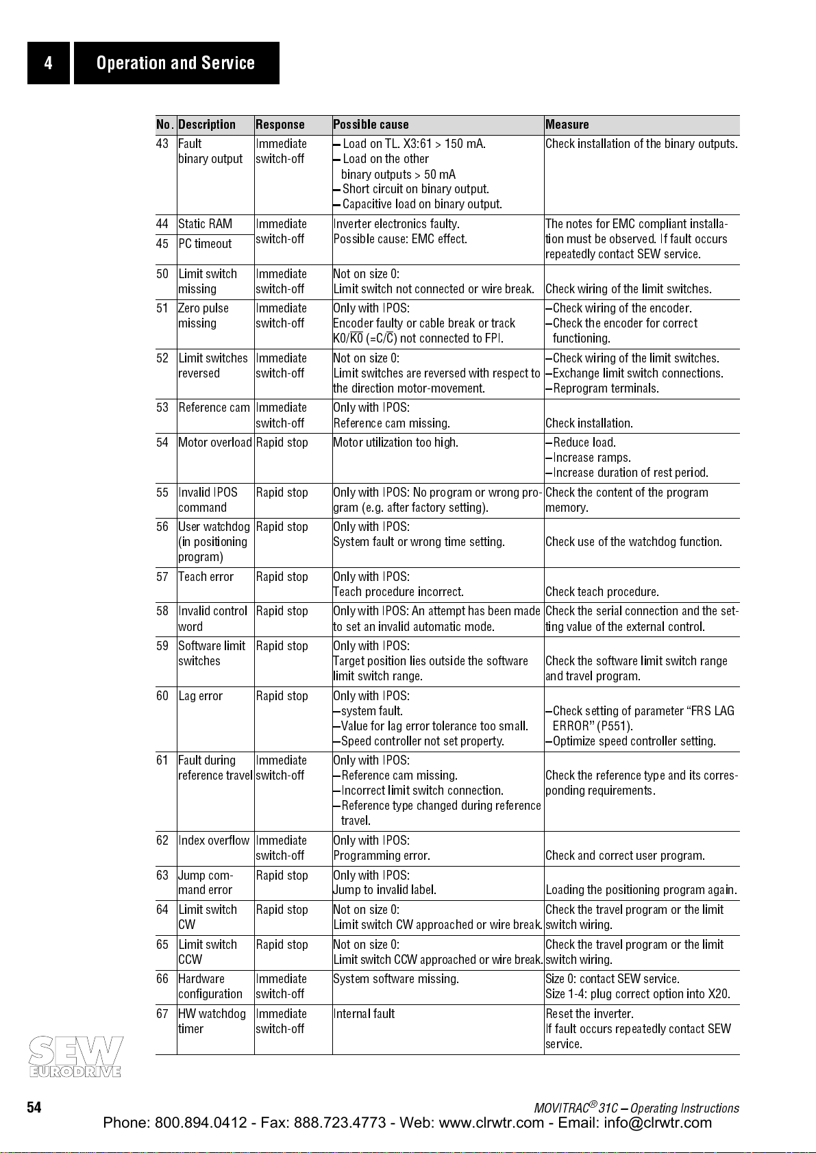
4 Operation and Service
Phone: 800.894.0412 - Fax: 888.723.4773 - Web: www.clrwtr.com - Email: info@clrwtr.com
No. Description Response Possible cause Measure
43 Fault
binary output
44 Static RAM Immediate
45 PC timeout
50 Limit switch
missing
51 Zero pulse
missing
52 Limit switches
reversed
53 Reference cam Immediate
54 Motor overload Rapid stop Motor utilization too high. Reduce load.
55 Invalid IPOS
command
56 User watchdog
(in positioning
program)
57 Teach error Rapid stop Only with IPOS:
58 Invalid control
word
59 Software limit
switches
60 Lag error Rapid stop Only with IPOS:
61 Fault during
reference travel
62 Index overflow Immediate
63 Jump com-
mand error
64 Limit switch CWRapid stop Not on size 0:
65 Limit switch
CCW
66 Hardware
configuration
67 HW watchdog
timer
Immediate
switch-off
switch-off
Immediate
switch-off
Immediate
switch-off
Immediate
switch-off
switch-off
Rapid stop Only with IPOS: No program or wrong pro-
Rapid stop Only with IP OS :
Rapid stop Only with IPOS: An attempt has been made
Rapid stop Only with IP OS :
Immediate
switch-off
switch-off
Rapid stop Only with IP OS :
Rapid stop Not on size 0:
Immediate
switch-off
Immediate
switch-off
Load on TL. X3:61 > 150 mA.
Load on the other
binary outputs > 50 mA
Short circuit on binary output.
Capacitive load on binary output.
Inverter electronics faulty.
Possible cause: EMC effect.
Not on size 0:
Limit switch not connected or wire break. Check wiring of the limit switches.
Only with IPOS:
Encoder faulty or cable break or track
(=C/C) not connected to FPI.
K0/K0
Not on size 0:
Limit switches are reversed with respect to
the direction motor-movement.
Only with IPOS:
Reference cam missing.
gram (e.g. after factory setting).
System fault or wrong time setting. Check use of the watchdog function.
Teach procedure incorrect. Check teach procedure.
to set an invalid automatic mode.
Target position lies outside the software
limit switch range.
system fault.
Value for lag error tolerance too small.
Speed controller not set property.
Only with IPOS:
Reference cam missing.
Incorrect limit switch connection.
Reference type changed during reference
travel.
Only with IPOS:
Programming error.
Jump to invalid label. Loading the positioning program again.
Limit switch CW approached or wire break.
Limit switch CCW approached or wire break.
System software missing. Size 0: contact SEW service.
Internal fault Reset the inverter.
Check installation of the binary outputs.
The notes for EMC compliant installa-
tion must be observed. If fault occurs
repeatedly contact SEW service.
Check wiring of the encoder.
Check the encoder for correct
functioning.
Check wiring of the limit switches.
Exchange limit switch connections.
Reprogram terminals.
Check installation.
Increase ramps.
Increase duration of rest period.
Check the content of the program
memory.
Check the serial connection and the set-
ting value of the external control.
Check the software limit switch range
and travel program.
Check setting of parameter FRS LAG
ERROR
Optimize speed controller setting.
Check the reference type and its corres-
ponding requirements.
Check and correct user program.
Check the travel program or the limit
switch wiring.
Check the travel program or the limit
switch wiring.
Size 1-4: plug correct option into X20.
If fault occurs repeatedly contact SEW
service.
(P551).
54
MOVITRAC® 31C Operating Instructions
Page 55

4.4 SEW Electronics Service
Phone: 800.894.0412 - Fax: 888.723.4773 - Web: www.clrwtr.com - Email: info@clrwtr.com
Operation and Service 4
If a fault cannot be corrected
, then please contact
(→ "After-Sales Service and Spare Parts").
If you return equipment for repair, please state:
- Serial number (→ nameplate)
- Type designation
- Service code data from the service label
- Description of the application (drive situation, control via terminals or serial interface)
- Connected motor (motor rated voltage, V or ∆ connection)
- Options installed
- Nature of the fault
- Circumstances the fault occured under
- Suspected cause
- Any abnormal circumstances, etc, that may have caused the fault.
®
The MOVITRAC
31C units have a service label, which is attached next to the nameplate and the
option label.
SEW Electronics Service
Example:
Sub-assemblies / Components
Fig. 25: Service label
1 2 3 4 5
13 15 13 14 10
31C110-503-4-00
Type identificationService code data
00591AEN
MOVITRAC® 31C Operating Instructions
55
Page 56

5 Technical Data
Phone: 800.894.0412 - Fax: 888.723.4773 - Web: www.clrwtr.com - Email: info@clrwtr.com
5 Technical Data
5.1 Basic units
5.1.1 General technical data
The following table contains the technical data for all MOVITRAC
®
31C frequency inverters, inde-
pendent of size and rated power.
MOVITRAC® 31C all unit sizes
Immunity to interference complies with EN 61800 - 3
Interference emission
with EMC-compliant wiring
Ambient temperature*
Derating
Ambient conditions
Storage temperature**
Enclosure IP20 (EN 60529 / NEMA1)
Duty type DB (EN 60149-1-1 and 1-3)
Altitude of installation h ≤ 1000m
*)Units for
**)In the case of extended storage, connect the unit to the mains supply for at least 5 minutes every 2 years,
as otherwise the service life of the unit may be reduced.
ϑ
)
)
< 0°C on request.
amb
ϑ
storage
ϑ
amb
conforms with interference supression level B to EN 55011 and EN 55014
complies with EN 61800 - 3
0°...+45°C
PN-reduction: 3.0% IN per K up to max. 60°C
EN 60721-3-3, class 3K3
-25°C...+70°C (EN 60721-3-3, class 3K3)
FBG keypad: -20°C...+60°C
IN-reduction: 1% per 100 m (330 ft)
from 1000 m (3300 ft) up to max. 2000 m (6600 ft)
MOVITRAC® 31C Unit Family
Fig. 26: MOVITRAC® 31C Unit Family
56
MOVITRAC® 31C Operating Instructions
00578EXX
Page 57

Technical Data 5
Phone: 800.894.0412 - Fax: 888.723.4773 - Web: www.clrwtr.com - Email: info@clrwtr.com
®
5.2 MOVITRAC
5.2.1 Basic units, sizes 0 and 1
MOVITRAC® 31C 005-233-4-00 011-233-4-00 008-233-4-00 015-233-4-00 022-233-4-00
Part number 826 321 3 826 322 1 826 323 X 826 324 8 826 325 6
Size 0 1
INPUT
Input voltages V
Permissible range
Input frequency f
Rated input current I
(at Vin = 3×230VAC) 125%
OUTPUT
Rated output power P
(at Vin = 3×200...240VAC)
Rated output current I
(at Vin = 3×230VAC)
Cont. output current = 125% IN*)I
(at Vin = 3×230VAC)
Constant load
Recommended motor power P
Variable torque load and constant
load without overload
Recommended motor power P
Current limit I
Internal current limit I
Minimum braking resistance R
value for 4-Q operation
Output voltage V
Output frequency f
resolution
base frequency f
PWM frequency f
GENERAL
Power losses at P
Cooling method (DIN 41751)
fan cooling
forced cooling/required air flow 40 m
Weight 2.4 kg (5.3 lb) 2.5 kg (5.5 lb) 4.5 kg (9.9 lb)
Dimensions W×H×D 105 × 188 × 189 mm
*) applies to f
To provide sufficient cooling leave a minimum clearance of 100 mm (4 in) above and below each unit.
Power ratings are based on a default setting of 4 kHz for the PWM frequency (P325/P345).
PWM
31C...-233 (230 V Units)
in
in
100%
in
N
N
cont
(0.75 HP)
Mot
Mot
max
BW
out
out
∆
f
out
base
PWM
N
= 4 kHz
P
lossmax
3 x 230 V
AC
Vin = 200VAC-10%...240VAC+10%
50 Hz ... 60 Hz ± 5%
2.8 A
3.5 A
AC
AC
4.0 A
5.0 A
AC
AC
3.3 A
4.1 A
AC
AC
6.7 A
8.4 A
AC
AC
7.8 A
9.8 A
1.3 kVA 2.0 kVA 1.6 kVA 2.7 kVA 3.4 kVA
3.2 A
AC
4.0 A
AC
0.55 kW
4.9 A
6.1 A
1.1 kW
(1.5 HP)
0.75 kW
(1.0 HP)
1.5 kW
(2.0 HP)
Motive: 150% I
Regenerative: 150% I
= 20...150% set via menu (P320 / P340)
max
AC
AC
N
N
4.0 A
AC
5.0 A
AC
0.75 kW
(1.0 HP)
1.1 kW
(1.5 HP)
7.3 A
AC
9.1 A
AC
1.5 kW
(2.0 HP)
2.2 kW
(3.0 HP)
Duration depending on utilization
8.6 A
10.8 A
2.2 kW
(3.0 HP)
3.0 kW
(4.0 HP)
68 Ω -10% 33 Ω -10%
Adjustable with parameter P329/P349, however max. V
0...400 Hz, f
= 0...40 Hz, f
min
= 5...400 Hz
max
in
0.05 Hz over the entire range
In steps: 50/60/87/104/120 Hz and continuously: 5...400 Hz
Adjustable: 4/8/12/16 kHz (P325/P345)
54 W 75 W 70 W 110 W 126 W
3
/h (24 ft3/min) 25 m3/h (15 ft3/min)
184 × 281 × 170 mm
(4.13 × 7.40 × 7.44 in)
(7.24 × 11.06 × 6.69 in)
AC
AC
AC
AC
M
M
n
n
MOVITRAC® 31C Operating Instructions
57
Page 58

5 Technical Data
Phone: 800.894.0412 - Fax: 888.723.4773 - Web: www.clrwtr.com - Email: info@clrwtr.com
5.2.2 Basic units, sizes 2 and 3
MOVITRAC® 31C 037-233-4-00 055-233-4-00 075-233-4-00
Part number 826 326 4 826 327 2 826 328 0
Size 2 3
INPUT
Input voltages V
Permissible range
Input frequency f
Rated input current Iin 100%
(at Vin = 3×230VAC) 125%
OUTPUT
Rated output power P
(at Vin = 3×200...240VAC)
Rated output current I
(at Vin = 3×230VAC)
Cont. output current = 125% IN*)I
M
M
(at Vin = 3×230VAC)
Constant load
n
Recommended motor power P
Variable torque load and constant
load without overload
n
Recommended motor power P
Current limit I
Internal current limit I
Minimum braking resistance R
value for 4-Q operation
Output voltage V
Output frequency f
resolution
base frequency f
PWM frequency f
GENERAL
Power losses at P
Cooling method (DIN 41751)
fan cooling
forced cooling/required air flow 50 m
Weight 5.9 kg (13 lb) 13 kg (28.7 lb)
Dimensions W×H×D 184 × 296 × 218 mm
*) applies to f
To provide sufficient cooling leave a minimum clearance of 100 mm (4 in) above and below each unit.
Power ratings are based on a default setting of 4 kHz for the PWM frequency (P325/P345).
PWM
N
= 4 kHz
P
lossmax
in
in
N
N
cont
3.7 kW (5.0 HP) 5.5 kW (7.5 HP) 7.5 kW (10 HP)
5.5 kW (7.5 HP) 7.5 kW (10 HP) 11 kW (15 HP)
Motive: 150% I
Regenerative: 150% I
27 Ω -10% 11 Ω -10%
3
max
∆
base
PWM
Mot
Mot
BW
out
out
f
out
(7.24 × 11.65 × 8.58 in)
3 x 230 V
AC
Vin = 200VAC-10%...240VAC+10%
50 Hz ... 60 Hz ± 5%
14.2 A
17.8 A
AC
AC
19.5 A
24.4 A
AC
AC
27.4 A
34.3 A
6.4 kVA 8.8 kVA 11.6 kVA
16 A
20 A
AC
AC
N
N
= 20...150% set via menu (P320 / P340)
max
22 A
AC
27.5 A
AC
Duration depending on utilization
Adjustable with parameter P329/P349, however max. V
0...400 Hz, f
= 0...40 Hz, f
min
= 5...400 Hz
max
29 A
36.3 A
AC
in
0.05 Hz over the entire range
In steps: 50/60/87/104/120 Hz and continuously: 5...400 Hz
Adjustable: 4/8/12/16 kHz (P325/P345)
223 W 305 W 390 W
/h (30 ft3/min) 100 m3/h (60 ft3/min)
220 × 405 × 264 mm
(8.66 × 15.94 × 10.39 in)
AC
AC
AC
58
MOVITRAC® 31C Operating Instructions
Page 59

Technical Data 5
Phone: 800.894.0412 - Fax: 888.723.4773 - Web: www.clrwtr.com - Email: info@clrwtr.com
®
5.3 MOVITRAC
5.3.1 Basic units, size 0
MOVITRAC® 31C 005-503-4-00 007-503-4-00 011-503-4-00 014-503-4-00
Part number 826 078 8 826 079 6 826 080 X 826 374 4
INPUT
Input voltages V
Permissible range
Input frequency f
Rated input current Iin 100%
= 3×400VAC) 125%
(at V
in
OUTPUT
Rated output power P
(at Vin = 3×380...500VAC)
Rated output current I
(at Vin = 3×400VAC)
Cont. output current = 125% IN*)I
(at Vin = 3×400VAC)
Constant load
Recommended motor power P
Variable torque load and constant
load without overload
Recommended motor power P
Current limit I
Internal current limit I
Minimum braking resistance R
value for 4-Q operation
Output voltage V
Output frequency f
resolution
base frequency f
PWM frequency f
GENERAL
Power losses at P
Cooling method (DIN 41751)
fan cooling
forced cooling/required air flow
Weight 2.4 kg (5.3 lb) 2.5 kg (5.5 lb)
Dimensions W×H×D 105 × 188 × 189 mm (4.13 × 7.40 × 7.44 in)
31C...-503 (400/500 V Units)
in
in
N
N
cont
Mot
Mot
max
BW
out
out
∆
f
out
base
PWM
N
P
lossmax
3 x 380 V
1.6 A
1.9 A
1.4 kVA 1.8 kVA 2.2 kVA 2.8 kVA
2.0 A
2.5 A
0.55 kW (0.75 HP) 0.75 kW (1.0 HP) 1.1 kW (1.5 HP) 1.5 kW (2.0 HP)
0.75 kW (1.0 HP) 1.1 kW (1.5 HP) 1.5 kW (2.0 HP) 2.2 kW (3.0 HP)
Regenerative: 150% I
46 W 54 W 68 W 75 W
/ 400 VAC / 415 VAC / 460 VAC / 480 VAC / 500 V
AC
Vin = 380VAC-10%...500VAC+10%
50 Hz ... 60 Hz ± 5%
AC
AC
AC
AC
Motive: 150% I
= 20...150% set via menu (P320 / P340)
max
1.9 A
2.4 A
2.5 A
3.1 A
N
AC
AC
AC
AC
N
2.4 A
2.9 A
3.2 A
4.0 A
AC
AC
AC
AC
3.5 A
4.4 A
4.0 A
5.0 A
Duration depending on utilization
200 Ω -10%
Adjustable with parameter P329/P349, however max. V
0...400 Hz, f
= 0...40 Hz, f
min
= 5...400 Hz
max
in
0.05 Hz over the entire range
In steps: 50/60/87/104/120 Hz and continuously: 5...400 Hz
Adjustable: 4/8/12/16 kHz (P325/P345)
40 m3/h (24 ft3/min)
AC
AC
AC
AC
AC
M
M
n
n
*) applies to f
PWM
= 4 kHz
To provide sufficient cooling leave a minimum clearance of 100 mm (4 in) above and below each unit.
Power ratings are based on a default setting of 4 kHz for the PWM frequency (P325/P345).
For V
= 3 x 500 VAC the permissible input and output currents are reduced by 20 % compared to the rated values.
mains
MOVITRAC® 31C Operating Instructions
59
Page 60

5 Technical Data
Phone: 800.894.0412 - Fax: 888.723.4773 - Web: www.clrwtr.com - Email: info@clrwtr.com
5.3.2 Basic units, size 1
MOVITRAC® 31C 008-503-4-00 015-503-4-00 022-503-4-00 030-503-4-00
Part number 826 332 9 826 333 7 826 334 5 826 335 3
INPUT
Input voltages V
Permissible range
Input frequency f
Rated input current I
(at Vin = 3×400VAC) 125%
OUTPUT
Rated output power P
(at Vin = 3×380...500VAC)
Rated output current I
(at Vin = 3×400VAC)
Cont. output current = 125% IN*)I
M
M
(at Vin = 3×400VAC)
Constant load
n
Recommended motor power P
Variable torque load and constant
load without overload
n
Recommended motor power P
Current limit I
Internal current limit I
Minimum braking resistance R
value for 4-Q operation
Output voltage V
Output frequency f
resolution
base frequency f
PWM frequency f
GENERAL
Power losses at P
Cooling method (DIN 41751)
fan cooling
forced cooling/required air flow
Weight 4.5 kg (9.9 lb)
Dimensions W×H×D 184 × 281 × 170 mm (7.24 × 11.06 × 6.69 in)
in
3 x 380 VAC / 400 VAC / 415 VAC / 460 VAC / 480 VAC / 500 V
AC
Vin = 380VAC-10%...500VAC+10%
in
100%
in
N
N
cont
Mot
Mot
max
BW
out
out
∆
f
out
base
PWM
N
P
lossmax
2.0 A
AC
2.5 A
AC
1.8 kVA 2.8 kVA 3.8 kVA 5.1 kVA
2.5 A
AC
3.1 A
AC
0.75 kW (1.0 HP) 1.5 kW (2.0 HP) 2.2 kW (3.0 HP) 3.0 kW (4.0 HP)
1.1 kW (1.5 HP) 2.2 kW (3.0 HP) 3.0 kW (4.0 HP) 4.0 kW (5.0 HP)
Motive: 150% I
Regenerative: 150% I
max
Adjustable with parameter P329/P349, however max. V
0...400 Hz, f
In steps: 50/60/87/104/120 Hz and continuously: 5...400 Hz
Adjustable: 4/8/12/16 kHz (P325/P345)
65 W 85 W 105 W 130 W
50 Hz ... 60 Hz ± 5%
3.5 A
4.4 A
4.0 A
5.0 A
N
AC
AC
AC
AC
N
5.0 A
AC
6.3 A
AC
5.5 A
AC
6.9 A
AC
Duration depending on utilization
= 20...150% set via menu (P320 / P340)
47 Ω -10%
= 0...40 Hz, f
min
= 5...400 Hz
max
0.05 Hz over the entire range
6.7 A
8.4 A
7.3 A
9.1 A
in
AC
AC
AC
AC
25 m3/h (15 ft3/min)
*) applies to f
PWM
= 4 kHz
To provide sufficient cooling leave a minimum clearance of 100 mm (4 in) above and below each unit.
Power ratings are based on a default setting of 4 kHz for the PWM frequency (P325/P345).
For V
60
= 3 x 500 VAC the permissible input and output currents are reduced by 20 % compared to the rated values.
mains
MOVITRAC® 31C Operating Instructions
Page 61

Technical Data 5
Phone: 800.894.0412 - Fax: 888.723.4773 - Web: www.clrwtr.com - Email: info@clrwtr.com
5.3.3 Basic units, size 2
MOVITRAC® 31C 040-503-4-00 055-503-4-00 075-503-4-00
Part number 826 336 1 826 337 X 826 338 8
INPUT
Input voltages V
in
Permissible range
Input frequency f
Rated input current I
100%
in
in
(at Vin = 3×400VAC) 125%
OUTPUT
Rated output power P
N
(at Vin = 3×380...500VAC)
Rated output current I
N
(at Vin = 3×400VAC)
Cont. output current = 125% IN*)I
cont
(at Vin = 3×400VAC)
Constant load
Recommended motor power P
Mot
Variable torque load and constant
load without overload
Recommended motor power P
Current limit I
Mot
max
Internal current limit I
Minimum braking resistance R
BW
value for 4-Q operation
Output voltage V
Output frequency f
resolution
base frequency f
PWM frequency f
∆
base
PWM
out
out
f
out
GENERAL
Power losses at P
N
P
lossmax
Cooling method (DIN 41751)
fan cooling
forced cooling/required air flow 50 m
Weight 5.9 kg (13 lb)
Dimensions W×H×D 184 × 296 × 218 mm (7.24 × 11.65 × 8.58 in)
3 x 380 VAC / 400 VAC / 415 VAC / 460 VAC / 480 VAC / 500 V
Vin = 380VAC-10%...500VAC+10%
50 Hz ... 60 Hz ± 5%
8.8 A
11 A
AC
AC
10.7 A
13.4 A
AC
AC
13.8 A
17.3 A
6.6 kVA 8.3 kVA 11 kVA
9.6 A
12 A
AC
AC
12 A
15 A
AC
AC
16 A
20 A
4.0 kW (5.0 HP) 5.5 kW (7.5 HP) 7.5 kW (10 HP)
5.5 kW (7.5 HP) 7.5 kW (10 HP) 11 kW (15 HP)
Motive: 150% I
Regenerative: 150% I
N
N
= 20...150% set via menu (P320 / P340)
max
Duration depending on utilization
47 Ω -10%
Adjustable with parameter P329/P349, however max. V
0...400 Hz, f
= 0...40 Hz, f
min
= 5...400 Hz
max
0.05 Hz over the entire range
In steps: 50/60/87/104/120 Hz and continuously: 5...400 Hz
Adjustable: 4/8/12/16 kHz (P325/P345)
190 W 230 W 310 W
3
/h (30 ft3/min)
AC
AC
AC
AC
AC
in
M
M
n
n
*) applies to f
PWM
= 4 kHz
To provide sufficient cooling leave a minimum clearance of 100 mm (4 in) above and below each unit.
Power ratings are based on a default setting of 4 kHz for the PWM frequency (P325/P345).
For V
= 3 x 500 VAC the permissible input and output currents are reduced by 20 % compared to the rated values.
mains
MOVITRAC® 31C Operating Instructions
61
Page 62

5 Technical Data
Phone: 800.894.0412 - Fax: 888.723.4773 - Web: www.clrwtr.com - Email: info@clrwtr.com
5.3.4 Basic units, size 3
MOVITRAC® 31C 110-503-4-00 150-503-4-00 220-503-4-00
Part number 826 308 6 826 309 4 826 310 8
INPUT
Input voltages V
Permissible range
Input frequency f
Rated input current I
(at Vin = 3×400VAC) 125%
OUTPUT
Rated output power P
(at Vin = 3×380...500VAC)
Rated output current I
(at Vin = 3×400VAC)
Cont. output current = 125% IN*)I
M
M
(at Vin = 3×400VAC)
Constant load
n
Recommended motor power P
Variable torque load and constant
load without overload
n
Recommended motor power P
Current limit I
Internal current limit I
Minimum braking resistance R
value for 4-Q operation
Output voltage V
Output frequency f
resolution
base frequency f
PWM frequency f
GENERAL
Power losses at P
Cooling method (DIN 41751)
fan cooling
forced cooling/required air flow 100 m
Weight 13 kg (28.7 lb)
Dimensions W×H×D 220 × 405 × 264 mm (8.66 × 15.94 × 10.39 in)
in
3 x 380 VAC / 400 VAC / 415 VAC / 460 VAC / 480 VAC / 500 V
AC
Vin = 380VAC-10%...500VAC+10%
in
100%
in
N
N
cont
Mot
Mot
max
BW
out
out
∆
f
out
base
PWM
N
P
lossmax
20 A
AC
24 A
AC
17 kVA 23 kVA 33 kVA
24 A
AC
30 A
AC
11 kW (15 HP) 15 kW (20 HP) 22 kW (30 HP)
15 kW (20 HP) 22 kW (30 HP) 30 kW (40 HP)
Motive: 150% I
N
Regenerative: 150% I
max
18 Ω -10% 15 Ω -10%
Adjustable with parameter P329/P349, however max. V
0...400 Hz, f
In steps: 50/60/87/104/120 Hz and continuously: 5...400 Hz
Adjustable: 4/8/12/16 kHz (P325/P345)
430 W 580 W 800 W
3
/h (60 ft3/min) 230 m3/h (135 ft3/min)
50 Hz ... 60 Hz ± 5%
27 A
AC
33 A
AC
33 A
AC
41 A
AC
N
Duration depending on utilization
= 20...150% set via menu (P320 / P340)
= 0...40 Hz, f
min
= 5...400 Hz
max
0.05 Hz over the entire range
39 A
49 A
47 A
58 A
AC
AC
AC
AC
in
*) applies to f
PWM
= 4 kHz
To provide sufficient cooling leave a minimum clearance of 100 mm (4 in) above and below each unit.
Power ratings are based on a default setting of 4 kHz for the PWM frequency (P325/P345).
For V
62
= 3 x 500 VAC the permissible input and output currents are reduced by 20 % compared to the rated values.
mains
MOVITRAC® 31C Operating Instructions
Page 63

Technical Data 5
Phone: 800.894.0412 - Fax: 888.723.4773 - Web: www.clrwtr.com - Email: info@clrwtr.com
5.3.5 Basic units, size 4
MOVITRAC® 31C 300-503-4-00 370-503-4-00 450-503-4-00
Part number 826 329 9 826 330 2 826 331 0
INPUT
Input voltages V
in
Permissible range
Input frequency f
Rated input current I
100%
in
in
(at Vin = 3×400VAC) 125%
OUTPUT
Rated output power P
N
(at Vin = 3×380...500VAC)
Rated output current I
N
(at Vin = 3×400VAC)
Cont. output current = 125% IN*)I
cont
(at Vin = 3×400VAC)
Constant load
Recommended motor power P
Mot
Variable torque load and constant
load without overload
Recommended motor power P
Current limit I
Mot
max
Internal current limit I
Minimum braking resistance R
BW
value for 4-Q operation
Output voltage V
Output frequency f
resolution
base frequency f
PWM frequency f
∆
base
PWM
out
out
f
out
GENERAL
Power losses at P
N
P
lossmax
Cooling method (DIN 41751)
fan cooling
forced cooling/required air flow 230 m
Weight 19 kg (41.9 lb) 20 kg (44.1 lb)
Dimensions W×H×D 220 × 555 × 264 mm (8.66 × 21.85 × 10.39 in)
3 x 380 VAC / 400 VAC / 415 VAC / 460 VAC / 480 VAC / 500 V
Vin = 380VAC-10%...500VAC+10%
50 Hz ... 60 Hz ± 5%
56 A
70 A
AC
AC
69 A
86 A
AC
AC
84 A
105 A
42 kVA 52 kVA 64 kVA
61 A
76 A
AC
AC
75 A
93 A
AC
AC
92 A
115 A
30 kW (40 HP) 37 kW (50 HP) 45 kW (60 HP)
37 kW (50 HP) 45 kW (60 HP) 55 kW (75 HP)
Motive: 150% I
Regenerative: 150% I
N
N
= 20...150% set via menu (P320 / P340)
max
Duration depending on utilization
12 Ω -10% 10 Ω -10% 8.2 Ω -10%
Adjustable with parameter P329/P349, however max. V
0...400 Hz, f
= 0...40 Hz, f
min
= 5...400 Hz
max
0.05 Hz over the entire range
In steps: 50/60/87/104/120 Hz and continuously: 5...400 Hz
Adjustable: 4/8/12/16 kHz (P325/P345)
1000 W 1200 W 1500 W
3
/h (135 ft3/min)
AC
AC
AC
AC
AC
in
M
M
n
n
*) applies to f
PWM
= 4 kHz
To provide sufficient cooling leave a minimum clearance of 100 mm (4 in) above and below each unit.
Power ratings are based on a default setting of 4 kHz for the PWM frequency (P325/P345).
For V
= 3 x 500 VAC the permissible input and output currents are reduced by 20 % compared to the rated values.
mains
MOVITRAC® 31C Operating Instructions
63
Page 64

5 Technical Data
Phone: 800.894.0412 - Fax: 888.723.4773 - Web: www.clrwtr.com - Email: info@clrwtr.com
5.4 MOVITRAC® 31C electronics data
MOVITRAC® 31C General electronic data
Voltage supply X2:31
for setpoint input
Setpoint input n2 X2:34
Internal setpoints n11/n12/n13 or n21/n22/n23 = 0...400 Hz
Frequency ramp generator
time ranges at ∆f
Auxiliary voltage output V = 24 VDC, current rating I
External voltage supply V
Binary inputs Electrically isolated via opto-coupler
Signal level +13...+30 V
Control functions X2:41
Binary outputs R
Signal level
Control functions X3:61 Binary output fixed assigned to
Measurement output R
Signal level 5 V-TTL, PWM pulsed with 100 Hz
Control functions X2:65 Measurement output → menu P634
Reference terminals X2:0 0V10 Reference potential for analog signals and terminal X2:31
Permissible cable section Single core: 0.20...2.5 mm
= 50 Hz
out
X2:35
+10VDC +5%/-0%, I
n2 = 0...+10V / -10V...+10V
Resolution: 9 Bit = 20 mV, sample time: 5 ms
= 40kΩ (external voltage supply)
R
i
= 20kΩ (supplied by X2:31)
R
i
1. ramp
2. ramp
t11/t21
t12/t22
= 3mA Reference voltages for setpoint pot.
max
n2 = 0...20 mA / 4...20 mA
Resolution: 8 Bit = 0.08 mA
Sample time: 5 ms
up: 0.0...2000 s
down: 0.0...2000 s
up=down: 0.0...2000 s
Rapid stop
Ramp
Motor. pot.
t13/t23
N
down: 0...9.95 s
t4
up: 2...60 s
down: 2...60 s
= 250 mA
max
= 24 VDC -15% / +20% (range 19.2...30 VDC)
According to EN 61131-2
Basic unit without options: IE ª 200 mA
ª 600 mA
E_max
≈ 3.0 k
i
≈ 10 mA
sample time: 5 ms
Ω
SPS compatible
According to EN 61131-2
CW/stop
= 150mA (short-circuit proof)
max
= 50mA (short-circuit proof)
max
X3:42/43/47/X14:48/49
X3:62 Binary output
Basic unit with options: I
(EN 61131-2)
1
=
=
-3...+5 V
0
≈ 100 Ω SPS compatible, response time: 5 ms
i
0 = 0 V 1 = 24 V
≈ 330 Ω, I
i
= 3 mA, sample time: 10 ms, max.cable length: 10 m (33 ft)
max
R
I
E
= contact closed
= contact open
Fixed assigned to
→
menu P60_
Important:
Do not apply an external voltage!
/Brake , I
→
menu P61_, I
X3:30/X14:30 0V24 Reference potential for binary signals
X3:60/X14:60 Bezug Reference for binary inputs X3:41/42/43/47 and X14:48/49
2
(AWG24...12)
2
Double core: 0.20...1 mm
(AWG24...17)
64
MOVITRAC® 31C Operating Instructions
Page 65
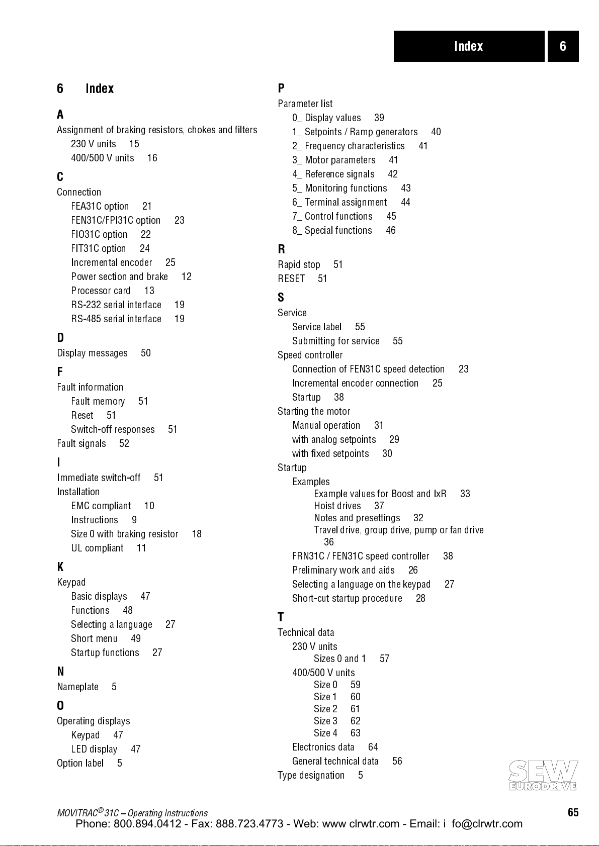
Index 6
Phone: 800.894.0412 - Fax: 888.723.4773 - Web: www.clrwtr.com - Email: info@clrwtr.com
6 Index
A
Assignment of braking resistors, chokes and filters
230 V units
400/500 V units
C
Connection
FEA31C option
FEN31C/FPI31C option
FIO31C option
FIT31C option
Incremental encoder
Power section and brake
Processor card
RS-232 serial interface
RS-485 serial interface
D
Display messages 50
F
Fault information
Fault memory
Reset
Switch-off responses
Fault signals
I
Immediate switch-off 51
Installation
EMC compliant
Instructions
Size 0 with braking resistor
UL compliant
K
Keypad
Basic displays
Functions
Selecting a language
Short menu
Startup functions
N
Nameplate 5
O
Operating displays
Keypad
LED display
Option label
51
52
48
47
5
15
9
49
47
21
22
24
13
51
10
11
47
16
27
25
51
27
23
12
19
19
18
P
Parameter list
0_ Display values
1_ Setpoints / Ramp generators
2_ Frequency characteristics
3_ Motor parameters
4_ Reference signals
5_ Monitoring functions
6_ Terminal assignment
7_ Control functions
8_ Special functions
39
41
42
45
46
43
44
R
Rapid stop 51
RESET
51
S
Service
Service label
Submitting for service
Speed controller
Connection of FEN31C speed detection
Incremental encoder connection
Startup
Starting the motor
Manual operation
with analog setpoints
with fixed setpoints
Startup
Examples
FRN31C / FEN31C speed controller
Preliminary work and aids
Selecting a language on the keypad
Short-cut startup procedure
55
55
38
31
29
30
Example values for Boost and IxR
Hoist drives
Notes and presettings
Travel drive, group drive, pump or fan drive
36
37
32
26
28
T
Technical data
230 V units
Sizes 0 and 1
400/500 V units
Size 0
Size 1
Size 2
Size 3
Size 4
Electronics data
General technical data
Type designation
59
60
61
62
63
5
64
57
56
41
40
25
38
27
23
33
MOVITRAC® 31C Operating Instructions
65
 Loading...