

SEW Eurodrive MOVITRAC 07 User Manual
Edition
Phone: 800.894.0412 - Fax: 888.723.4773 - Web: www.clrwtr.com - Email: info@clrwtr.com
MOVITRAC® 07 Communication
06/2003
Manual
10565310 / EN
SEW-EURODRIVE

Contents
Phone: 800.894.0412 - Fax: 888.723.4773 - Web: www.clrwtr.com - Email: info@clrwtr.com
1 Important Notes................................................................................................. 4
2 Introduction .......................................................................................................5
2.1 Technical data........................................................................................... 5
2.2 MOVILINK® and system bus....................................................................5
2.3 Fieldbus .................................................................................................... 8
3 Installation ......................................................................................................... 9
3.1 System bus (SBus) installation ................................................................. 9
4 System Bus Communication Slave............................................................... 11
4.1 Data exchange with a slave via MOVILINK®.......................................... 11
4.2 Setting parameters via the SBus.............................................................15
4.3 Project planning example for SBus......................................................... 18
5 System Bus Communication Master.............................................................20
5.1 MOVITRAC® 07 as MOVILINK® master................................................20
5.2 Data exchange via profile-independent variable telegrams....................23
5.3 Programming of the data exchange in LOGODrive ................................31
6 Unit Profile....................................................................................................... 32
6.1 Scaling of process data........................................................................... 32
6.2 Definition of the control word...................................................................33
6.3 Connection of control commands............................................................33
6.4 Setpoint cascade ....................................................................................38
6.5 Status word definition.............................................................................. 40
7 Operation and Service....................................................................................43
7.1 Startup SBus...........................................................................................43
7.2 Return codes for parameter setting.........................................................44
8 Monitoring Functions......................................................................................46
8.1 Timeout error .......................................................................................... 46
9 Bus Diagnostics.............................................................................................. 47
9.1 Diagnostics of process input data and output data.................................47
10 Parameter List ................................................................................................ 49
10.1 Explanation of the table header ..............................................................49
10.2 Conversion index ....................................................................................50
10.3 Complete parameter list, sorted by parameter numbers......................... 51
11 Index.................................................................................................................57
Manual – MOVITRAC® 07 Communication
3
1
Phone: 800.894.0412 - Fax: 888.723.4773 - Web: www.clrwtr.com - Email: info@clrwtr.com
Important Notes
1 Important Notes
Handbuch
• This manual does not replace the detailed operating instructions!
• Installation and startup only by trained personnel observing applicable acci-
dent prevention regulations and the MOVITRAC
Documentation
Bus systems
• Read this manual carefully before you install or operate the MOVITRAC® 07 frequency inverter with communication link.
• We assume that you are familiar the the MOVITRAC
reading this manual.
• Consult the existing documentation. It is a prerequisite for trouble-free operation and
fulfillment of any warranty claims.
General safety notes on bus systems:
This communication system will make it possible for you to match the MOVITRAC
to the specifics of your application. As with all bus systems, there is a danger of invisible,
external (as far as the inverter is concerned) modifications to the parameters, which give
rise to changes in the inverter behavior. This may result in unexpected (not uncontrolled,
though!) system behavior.
®
07 operating instructions!
®
07 system manual prior to
®
unit
Safety and warning notes
Observe the safety and warning notes contained in this documentation!
Electrical hazard
Possible consequences: Severe or fatal injuries.
Hazard
Possible consequences: Severe or fatal injuries.
Hazardous situation
Possible consequences: Slight or minor injuries.
Harmful situation
Possible consequences: Damage to the unit and the environment.
Tips and useful information.
4
Manual – MOVITRAC® 07 Communication

2 Introduction
Phone: 800.894.0412 - Fax: 888.723.4773 - Web: www.clrwtr.com - Email: info@clrwtr.com
The units of the MOVITRAC® 07 series are available in standard and LOGODrive design.
Units in standard design can only be operated as slaves. The master functions are not
available in this unit.
2.1 Technical data
System Bus
(SBus)
Standard CAN specification 2.0 parts A and B
Baud rate either 125, 250, 500 or 1000 kbaud, factory setting 500 kbaud
ID range 0 ... 2047
Address can be set with parameter P813: 0 ... 63
Number of process
data words
Cable length depending on the baud rate, max. 320 m
Number of stations max. 64
fixed setting: 3 PD
Introduction
Technical data
2
2.2 MOVILINK® and system bus
MOVILINK® profile
The MOVILINK® profile is an SEW-specific profile.
®
The MOVILINK
profile makes for the data exchange between a higher-level master
and several SEW inverters. Masters may take the form of programmable logic controllers, PCs or even SEW inverters with PLC functions (units with IPOS
bus gateways). SEW inverters usually function as slaves in the bus system.
®
The MOVILINK
profile offers the following functions:
• Automation
– Drive control
– Parameter setting of the drives
•Startup
• Visualization
®
The MOVILINK
profile does not depend on any specific transmission medium. This fact
makes the functions described in the MOVILINK
sion as well as transmission via a fieldbus system.
plus®
or UFx field-
®
profile available for serial transmis-
Manual – MOVITRAC® 07 Communication
5

2
Phone: 800.894.0412 - Fax: 888.723.4773 - Web: www.clrwtr.com - Email: info@clrwtr.com
Introduction
MOVILINK® and system bus
Features
The MOVILINK® profile has a range of functions comparable to other fieldbus systems,
such as:
•PROFIBUS
• INTERBUS
• CANopen
• DeviceNet
®
The MOVILINK
• Access to all drive parameters and functions in SEW inverters. The profile will help
you manage the following tasks:
–Startup
–Service
– Diagnostics
– Visualization
– Automation
• In addition, the MOVILINK
– Fast process data exchange
– Comprehensive parameter access
– Network management
• The MOVITOOLS startup and diagnostic tools use the MOVITOOLS
communication with the inverter.
profile offers the following functions:
®
profile offers the following services:
®
profile for
System bus
(SBus)
The SBus is a CAN bus according to the CAN specification 2.0, parts A and B. The SBus
supports all services offered by the MOVILINK
exchange IPOS
MOVITRAC
The SBus controls the inverter via the fast process data.
You can specify the following setpoints with the process data telegrams:
• Setpoint speed
• Integrator time
• Acceleration/deceleration
You can specify the following drive functions with the process data telegrams:
• Enable
• Controller inhibit
• Standard stop
• Rapid stop
plus®
variables via the SBus regardless of the profile.
®
07 offers digital access to all drive parameters and functions via the SBus.
®
SEW unit profile. In addition, you can
6
Manual – MOVITRAC® 07 Communication
Introduction
Phone: 800.894.0412 - Fax: 888.723.4773 - Web: www.clrwtr.com - Email: info@clrwtr.com
MOVILINK® and system bus
You can read back the following actual values from the inverter with the process data
telegrams:
• Actual speed
• Current
•Unit state
• Error code
• Reference signals
®
You can generate applications with the MOVILINK
parameters in the higher-level automation device. This setup eliminates the need for
manual parameter setting of the inverter.
plus®
IPOS
with other MOVILINK
via IPOS
provides the MOVLNK command to exchange parameter and process data
plus®
and control other units. Only LOGODrive units can serve as masters.
®
stations. As a result, MOVITRAC® 07 can operate as the master
profile that store all important drive
2
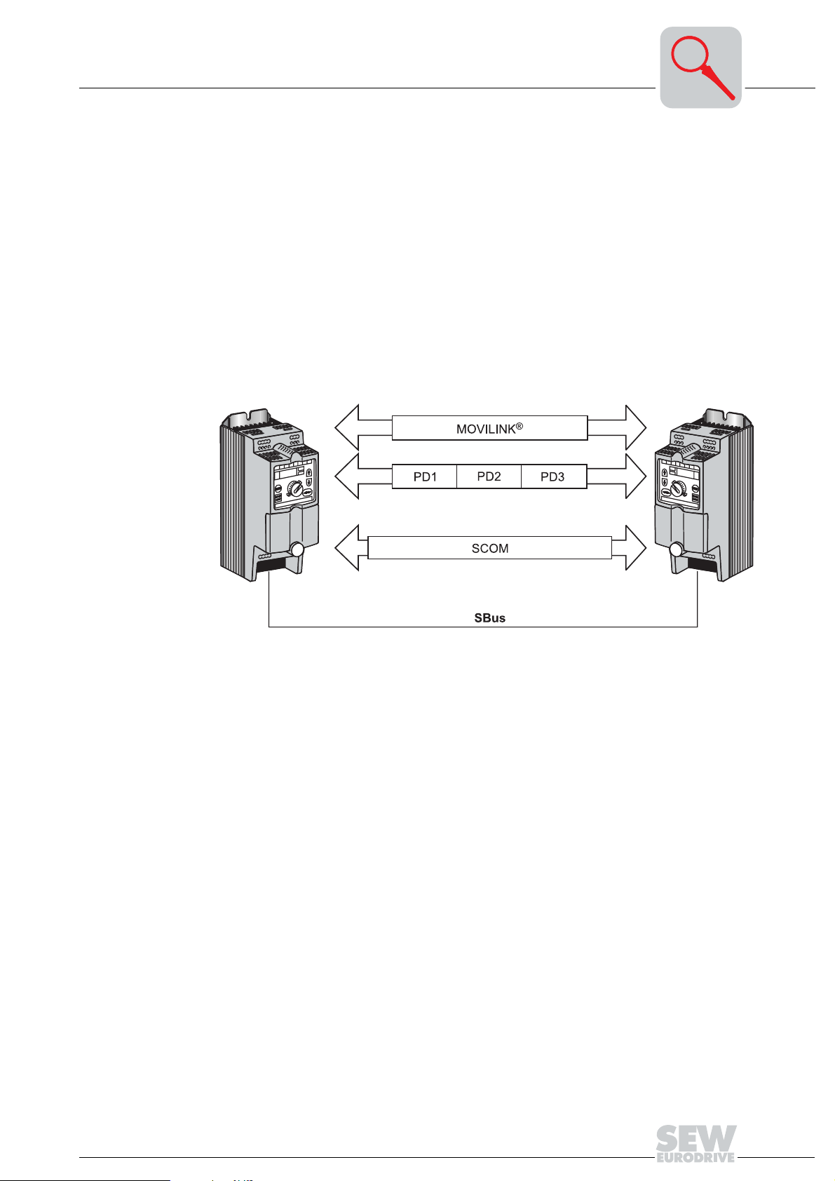
Variable telegrams
Figure 1: Variants of SBus communication
05886AXX
Using the SBus requires additional monitoring functions such as time monitoring (SBus
timeout time) or special emergency off concepts.
®
The MOVITRAC
07 inverter offers numerous diagnostic options for startup and service
purposes.
The MOVITOOLS software offers a more convenient diagnostic option:
You can set all drive parameters and display the bus and unit status in detail with the
SHELL and STATUS programs.
You can monitor the data exchange with the bus monitor or use the control mode to pre-
set the data exchange.
The cyclical and acyclical exchange of variables via SBus offers an interface for the exchange of variables between several MOVITRAC
®
07 units. You can also perform profile-specific partial implementations for non-SEW units. These non-SEW units may support the CANopen or other protocol.
Manual – MOVITRAC® 07 Communication
7
2
Phone: 800.894.0412 - Fax: 888.723.4773 - Web: www.clrwtr.com - Email: info@clrwtr.com
2.3 Fieldbus
Introduction
Fieldbus
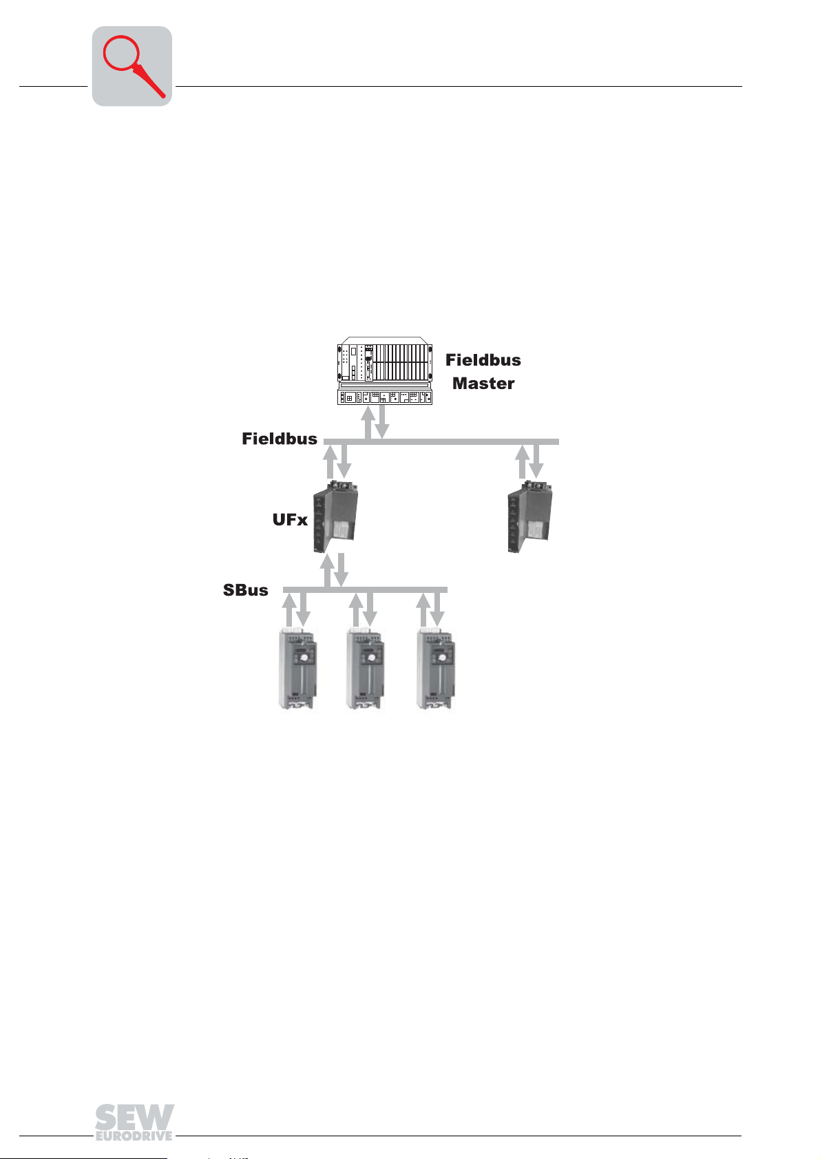
You can use the UFx11A fieldbus gateways to integrate the MOVITRAC® 07 into the
following fieldbus systems:
• PROFIBUS-DP
• INTERBUS
• DeviceNet
• CANopen
You can connect several inverters to the UFx11A fieldbus gateway via the SBus. The
UFx11A fieldbus gateway connects the fieldbus and SBus.
Figure 2: System overview fieldbus master – UFx11A – inverter
8
05929AXX
Manual – MOVITRAC® 07 Communication

3 Installation
Phone: 800.894.0412 - Fax: 888.723.4773 - Web: www.clrwtr.com - Email: info@clrwtr.com
3.1 System bus (SBus) installation
Installation
System bus (SBus) installation
3
Figure 3: System bus connection MOVITRAC® 07
S12 = System bus terminating resistor
SC11 = System bus high
SC12 = System bus low
SC21 = System bus high
SC22 = System bus low
GND = System bus reference
SBus MOVITRAC® 07: Connect the communication terminals to SC11/SC12. SC21/
SC22 is only active when S12 = OFF.
Cable specification
Shield contact
• Use a 2-core twisted and shielded copper cable (data transmission cable with shield
comprising copper braiding). The cable must meet the following specifications:
– Cable cross section 0.75 mm
– Cable resistance 120 Ω at 1 MHz
– Capacitance per unit length ≤ 40 pF/m (12 pF/ft) at 1 kHz
Suitable cables include CAN bus or DeviceNet cables.
• Connect the shield at either end to the electronics shield clamp of the inverter or the
master control and ensure the shield is connected over a large area. Also connect
the ends of the shield to GND.
2
(AWG 18)
05987AXX
Manual – MOVITRAC® 07 Communication
9

3
Phone: 800.894.0412 - Fax: 888.723.4773 - Web: www.clrwtr.com - Email: info@clrwtr.com
Installation
System bus (SBus) installation
Cable length
Terminating
resistor
• The permitted total cable length depends on the baud rate setting of the SBus
(P816):
– 125 kbaud → 320 m (1,056 ft)
– 250 kbaud → 160 m (528 ft)
– 500 kbaud → 80 m (264 ft)
– 1000 kbaud → 40 m (132 ft)
• Switch on the system bus terminating resistor (S12 = ON) at the start and end of the
system bus connection. Switch off the terminating resistor on the other units (S12 =
OFF).
• There must not be any potential displacement between the units connected using the
SBus. Take suitable measures to avoid a potential displacement, such as connecting
the unit ground connectors using a separate lead.
10
Manual – MOVITRAC® 07 Communication

System Bus Communication Slave
Phone: 800.894.0412 - Fax: 888.723.4773 - Web: www.clrwtr.com - Email: info@clrwtr.com
Data exchange with a slave via MOVILINK®
4 System Bus Communication Slave
4
4.1 Data exchange with a slave via MOVILINK
CAN bus identifier
Communication via MOVILINK® incorporates the data exchange of parameter and process data telegrams. The MOVITRAC
this process. Only LOGODrive units can serve as masters.
As slave, the unit can receive and answer parameter and process data messages via
the SBus.
Communication with a master control works with different telegrams types. These types
of telegrams can be divided into two categories:
• Process data telegrams
• Parameter telegrams
On the SBus, it is necessary to differentiate between these various types of telegrams
by means of the identifiers (ID). You create the ID of an SBus telegram by indicating the
telegram type and the SBus address. Set the SBus address using parameters P813 or
P814. P813 is the SBus address while P814 is the SBus group address.
The CAN bus identifier consists of 11 bits. The 11 bits of the identifier form three groups:
• Function (bits 0 ... 2)
• Address (bits 3 ... 8)
• Process data/parameter data switch (bit 9)
®
®
07 unit can communicate as master or slave in
Table 1: CAN identifier for SBus in MOVILINK® profile
543210
↓↓↓↓↓↓
0X XXX
Bit109876543210
Address Function
0 = process data telegram
1 = parameter data telegram
Reserved = 0
Bit 9 distinguishes between process and parameter data telegrams. Bit 10 is reserved
and must be 0. The address of parameter and process data telegrams includes the
SBus address (P813) of the unit that is addressed by a request; the address of group
parameter and group process data telegrams includes the SBus group address (P814).
Manual – MOVITRAC® 07 Communication
11

4
Phone: 800.894.0412 - Fax: 888.723.4773 - Web: www.clrwtr.com - Email: info@clrwtr.com
System Bus Communication Slave
Data exchange with a slave via MOVILINK®
Creating the identifiers
Process data telegrams
The following table shows the relationship between the type of telegram and the address
when creating the identifiers for SBus MOVILINK
Identifier Telegram type
8 × SBus address + 3 Process output data telegram (PO)
8 × SBus address +4 Process input data telegram (PI)
8 × SBus group address + 6 Group process output data telegram (GPO)
8 × SBus address + 512 + 3 Parameter request telegram
8 × SBus address + 512 +4 Parameter response telegram
8 × SBus group address + 512 + 6 Group parameter request telegram
®
telegrams:
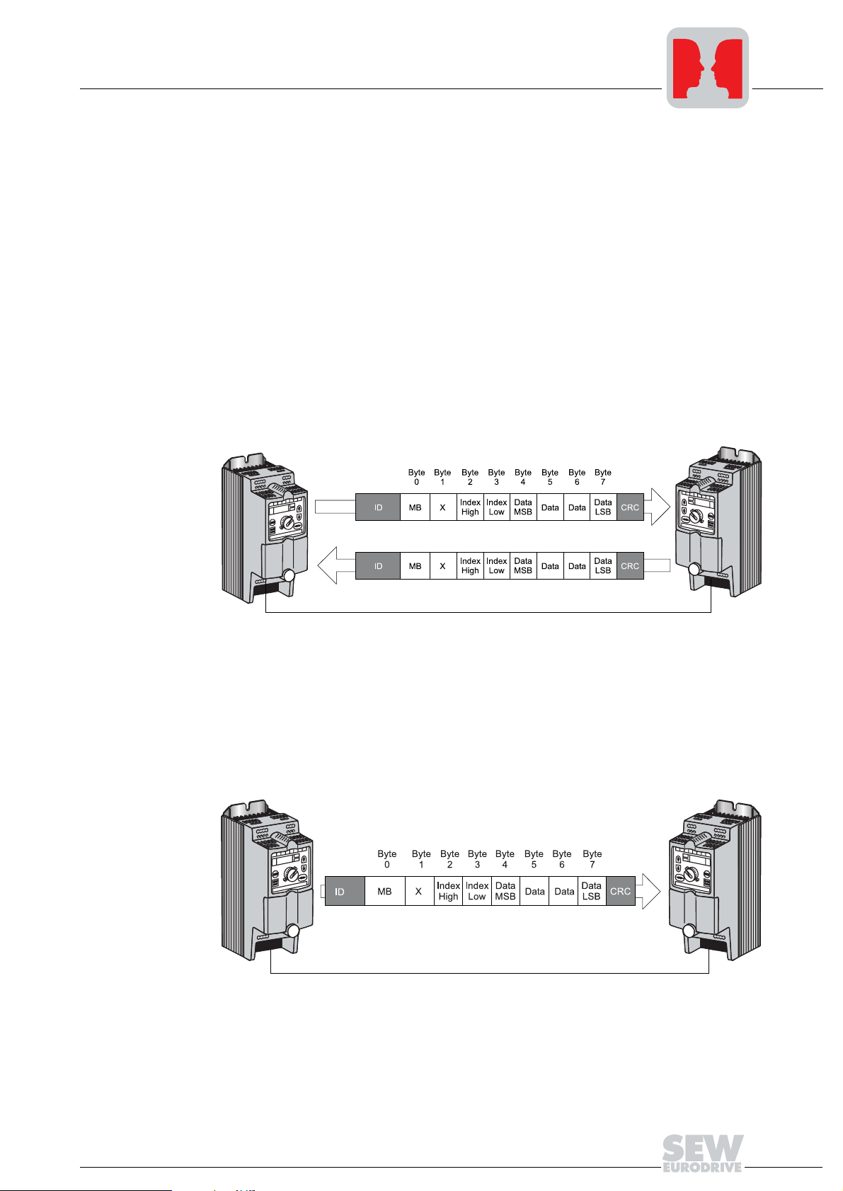
Process data telegrams are comprised of a process output and a process input data
telegram. The process output data telegram is sent from the master to a slave; it contains the setpoint values for the slave. A process input data telegram is sent from the
slave to the master after receipt of the process output telegram; it contains the actual
values of the slave.
The fixed setting for the number of process data is "3 process data words."
The resulting CAN telegram always includes 6 byte user data.
Group process
data telegram
Figure 4: Process data telegrams
05887AXX
The group process data telegram is sent from the master to one or more slaves with the
same SBus group address. Its structure is the same as the process output data telegram. Use this telegram to send the same setpoint values to several slaves that share
the same SBus group address. The slaves do not respond to the telegram.
05890AXX
Figure 5: Group process data telegram
12
Manual – MOVITRAC® 07 Communication
System Bus Communication Slave
Phone: 800.894.0412 - Fax: 888.723.4773 - Web: www.clrwtr.com - Email: info@clrwtr.com
Data exchange with a slave via MOVILINK®
4
Parameter telegrams
Parameter telegrams are made up of a parameter request telegram and a parameter response telegram.
The master sends the parameter request telegram to read or write a parameter value. It
has the following components:
• Management byte
• Index high byte
• Index low byte
• Four data bytes
The management byte indicates the service that is to be performed. The index indicates
the parameter for which the service will be performed. The four data bytes contain the
numerical value to be read or written.
The resulting CAN telegram always includes 8 byte user data.
The slave sends the parameter response telegram in response to the parameter request
telegram sent by the master. The request and response telegrams have the same structure.
Group parameter
telegram
Figure 6: Parameter telegrams
05889AXX
MB = Management byte
X = Reserved
The master sends the group parameter telegram to one or more slaves with the same
SBus group address. Its structure is the same as the parameter request telegram. You
can only write parameters of the slave units with this telegram. The slaves do not respond to the telegram.
05888AXX
Figure 7: Group parameter telegram
MB = Management byte
X = Reserved
Manual – MOVITRAC® 07 Communication
13
4
Phone: 800.894.0412 - Fax: 888.723.4773 - Web: www.clrwtr.com - Email: info@clrwtr.com
System Bus Communication Slave
Data exchange with a slave via MOVILINK®
Parameter settings
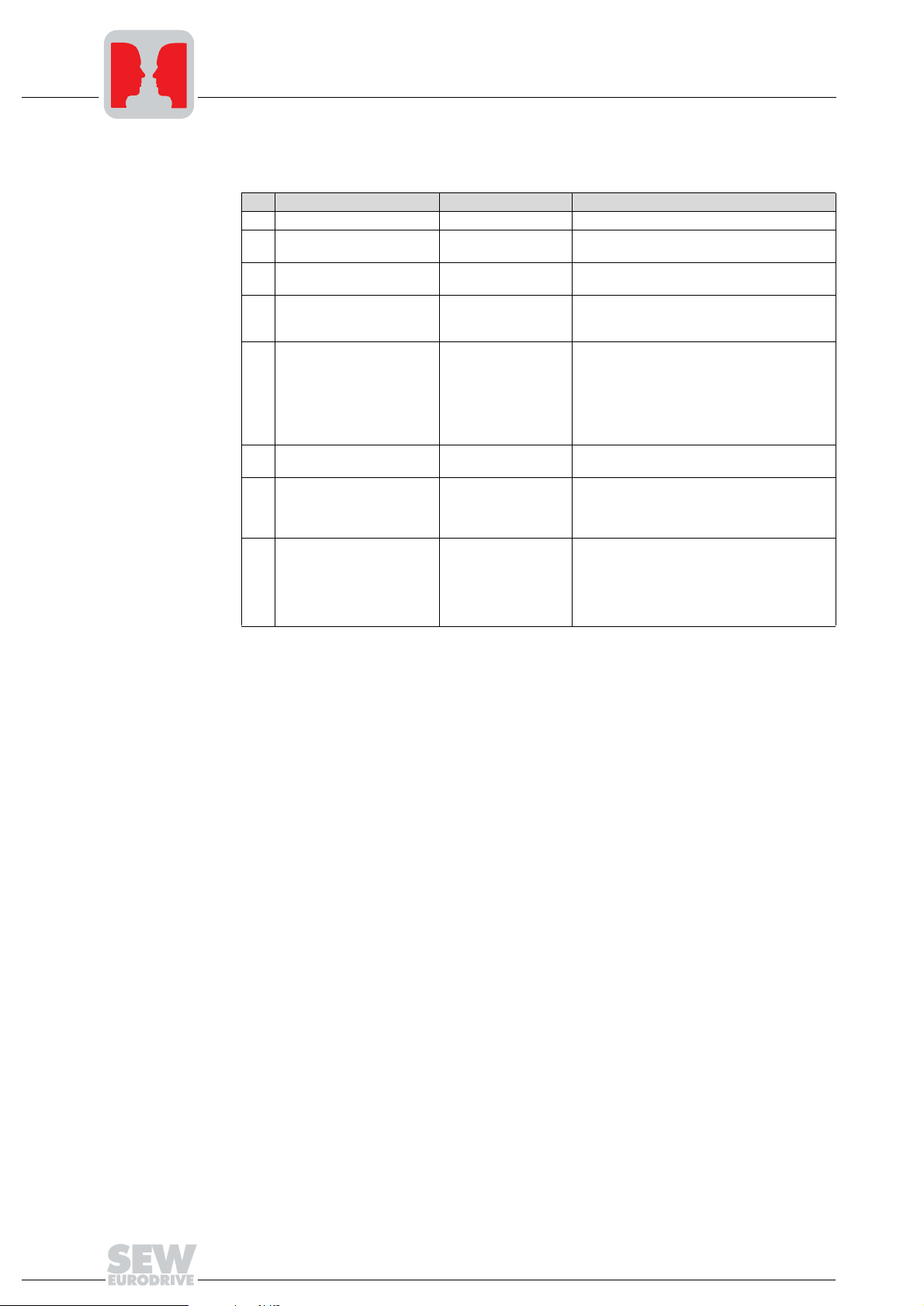
The following parameters have to be set on the MOVITRAC® 07 for communication via
the SBus:
Par. Name Setting Meaning
100 Setpoint source SBus The inverter gets its setpoint from the SBus.
101 Control signal source SBus
813 SBus address 0...63
814 SBus group address 0...63
815 SBus timeout delay 0...650 s
816 SBus baud rate
870
PO1 setpoint description
871
PO2 setpoint description
872
PO3 setpoint description
873
PI1 actual value description
874
PI2 actual value description
875
PI3 actual value description
876
PO data enable
125/250/500/1000
kbaud
Factory setting:
CTRL. WORD 1
SPEED
NO FUNCTION
Factory setting:
STATUS WORD 1
SPEED
NO FUNCTION
ON
The inverter gets its control commands from
the SBus.
Setting of the SBus address used for the
exchange of parameter and process data.
Setting of the SBus group address for the
receipt of group parameter data and group process data.
Set the monitoring time for data transmission
via the system bus with P815. MOVITRAC
reacts with the error response 'rapid stop/fault'
if there is no data traffic via the system bus for
the time period set in P815. No monitoring of
data transmission via the system bus takes
place when P815 is set to the value 0.
The transmission speed of the SBus is set.
The content of the process output data words
PO1/PO2/PO3 is defined. This step is necessary so that the MOVITRAC
the appropriate setpoints.
The content of the process input data words
PI1/PI2/PI3 is defined. This step is necessary
so that the MOVITRAC
appropriate actual values. The process data
must be enabled for the unit to accept the setpoints.
®
07 can allocate
®
07 can allocate the
®
07
14
Manual – MOVITRAC® 07 Communication
System Bus Communication Slave
Phone: 800.894.0412 - Fax: 888.723.4773 - Web: www.clrwtr.com - Email: info@clrwtr.com
4.2 Setting parameters via the SBus
The MOVITRAC® 07 inverter supports the MOVILINK® parameter channel with the
SBus.
Setting parameters via the SBus
4
Services
Structure of the
parameter telegram
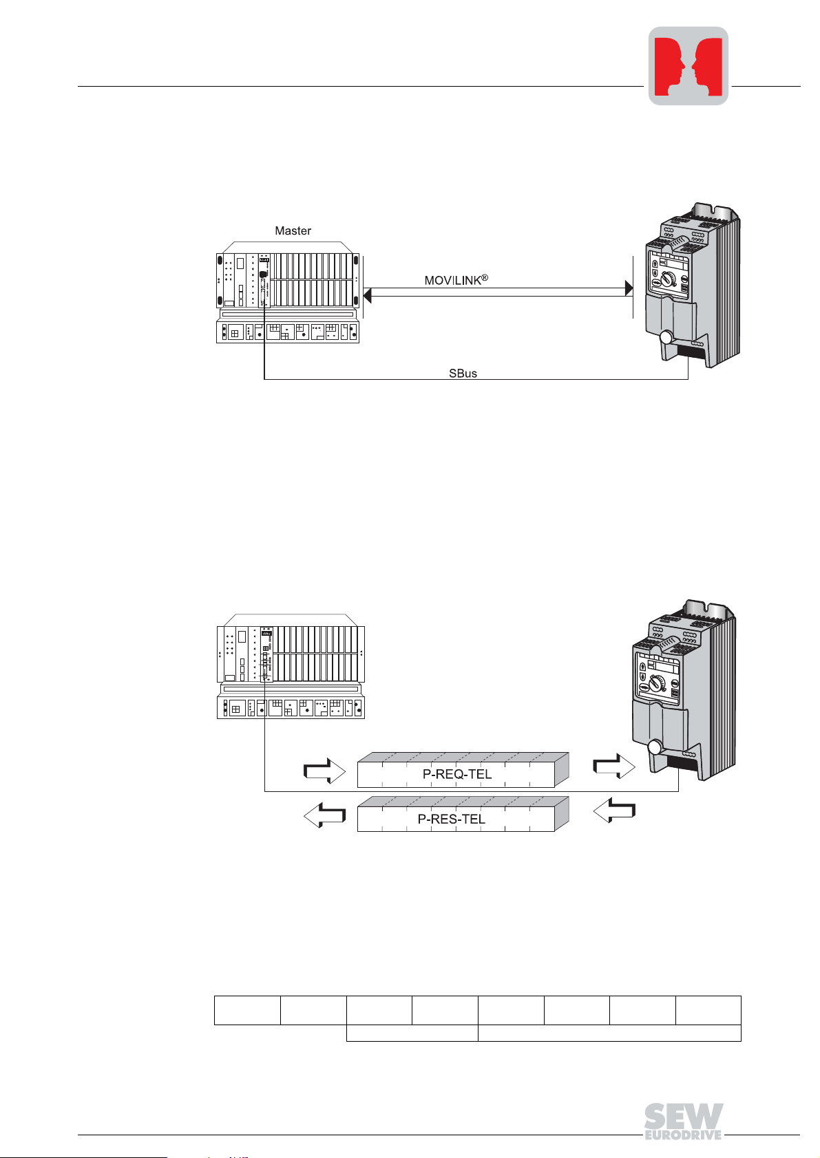
Figure 8: Services available via the SBus
05891AXX
The inverter parameters are read and written via the SBus with the MOVILINK® parameter channel services of the application layer (layer 7 of the ISO/OSI model for communication).
Parameter setting of field devices via fieldbus systems requires functions and services
such as READ and WRITE for reading and writing of parameters. The parameter telegram in the MOVILINK
®
profile serves such a purpose. The parameter data can be read
and written via parameter telegrams.
Figure 9: Parameter telegram for SBus
P-REQ-TEL = Parameter-Request-Telegram
P-REQ-TEL = Parameter-Response-Telegram
The following table shows the structure of the parameter telegram. In principle, it is
made up of a management byte, an index word and four data bytes.
Byte 0 Byte 1 Byte 2 Byte 3 Byte 4 Byte 5 Byte 6 Byte 7
Manage-
ment
Manual – MOVITRAC® 07 Communication
Reserved Index high Index low Data MSB Data Data Data LSB
Parameter index 4 byte data
05892AXX
15

4
Phone: 800.894.0412 - Fax: 888.723.4773 - Web: www.clrwtr.com - Email: info@clrwtr.com
System Bus Communication Slave
Setting parameters via the SBus
Byte 0: Management of the parameter telegram
The entire parameter setting sequence is coordinated with byte 0: "Management". This
byte provides important service parameters such as service identifier, data length, version and status of the service performed. The following table shows that bits 0 ... 3 include the service identifier and define the service to be performed. Bit 4 and bit 5 specify
the data length in bytes for the WRITE service. This setting should be 4 bytes for all SEW
inverters.
• Bit 6 = 0: Asynchronous response (must be set to zero)
Status bit 7 indicates whether it was possible to carry out the service properly or if there
were errors.
Byte 0: Management
MSB LSB
Bit:7654321 0
Service identifier:
0000 = No service
0001 = Read parameter
0010 = Write parameter
0011 = Write parameter volatile
0110 = Read default
1000 = Read attribute
Data length:
11 = 4 bytes
= 0
Byte 1
Bytes 2 and 3:
Index addressing
Byte 4 ... 7: Data
range
Status bit:
0 = No error during execution of service
1 = Error during execution of service
Byte 1 should be considered reserved and must be set to 0x00.
Byte 2: Index high and byte 3: Index low determines the parameter read or written via
the fieldbus system. The parameters of an inverter are addressed with a uniform index
regardless of the connected fieldbus system.
The data are located in byte 4 to byte 7 of the parameter telegram. This means up to 4
bytes of data can be transmitted per service. The data are always entered with right-justification so that byte 7 contains the least significant data byte (Data LSB) while byte 4
is the most significant data byte (Data MSB).
Byte 0 Byte 1 Byte 2 Byte 3 Byte 4 Byte 5 Byte 6 Byte 7
Manage-
ment
Reserved Index high Index low Data MSB Data Data Data LSB
High byte 1 Low byte 1 High byte 2 Low byte 2
High word Low word
Double word
16
Manual – MOVITRAC® 07 Communication

System Bus Communication Slave
Phone: 800.894.0412 - Fax: 888.723.4773 - Web: www.clrwtr.com - Email: info@clrwtr.com
Setting parameters via the SBus
4
Successful execution of service
Incorrect execution of a service
Return codes for
parameter setting
The successful execution of a service is indicated by a status bit not set in the management byte. Byte 4 ... 7 of the parameter response telegram contain the data corresponding to the service.
An incorrect execution of a service is indicated by setting the status bit in the management byte. If the status bit indicates an error, the error code is entered in structured form
in the data range (byte 4 ...7) of the parameter telegram.
Byte 0 Byte 1 Byte 2 Byte 3 Byte 4 Byte 5 Byte 6 Byte 7
Manage-
ment
Reserved Index high Index low Error class Error code
Add. code
high
Add. code
low
↓
Status bit = 1: Incorrect execution of a service
The return codes sent to the parameter-setting master in case of an incorrect execution
of a service include detailed information concerning the cause of the error. These return
codes are usually structured according to DIN 19245 T2. The system distinguishes between the following elements:
• Error class
• Error code
• Additional code
The operating instructions and the system manual include a description of the errors.
Special cases
• Errors in parameter settings
An incorrect code was entered in the management byte during execution of a read
or write service via SBus.
®
In this case, the MOVITRAC
Code (dec) Meaning
Error class: 5 Service
Error code: 5 Illegal value
Add. code
high:
Add. code low: 0–
0–
07 firmware prompts the following return code:
Manual – MOVITRAC® 07 Communication
17
4
Phone: 800.894.0412 - Fax: 888.723.4773 - Web: www.clrwtr.com - Email: info@clrwtr.com
System Bus Communication Slave
Project planning example for SBus
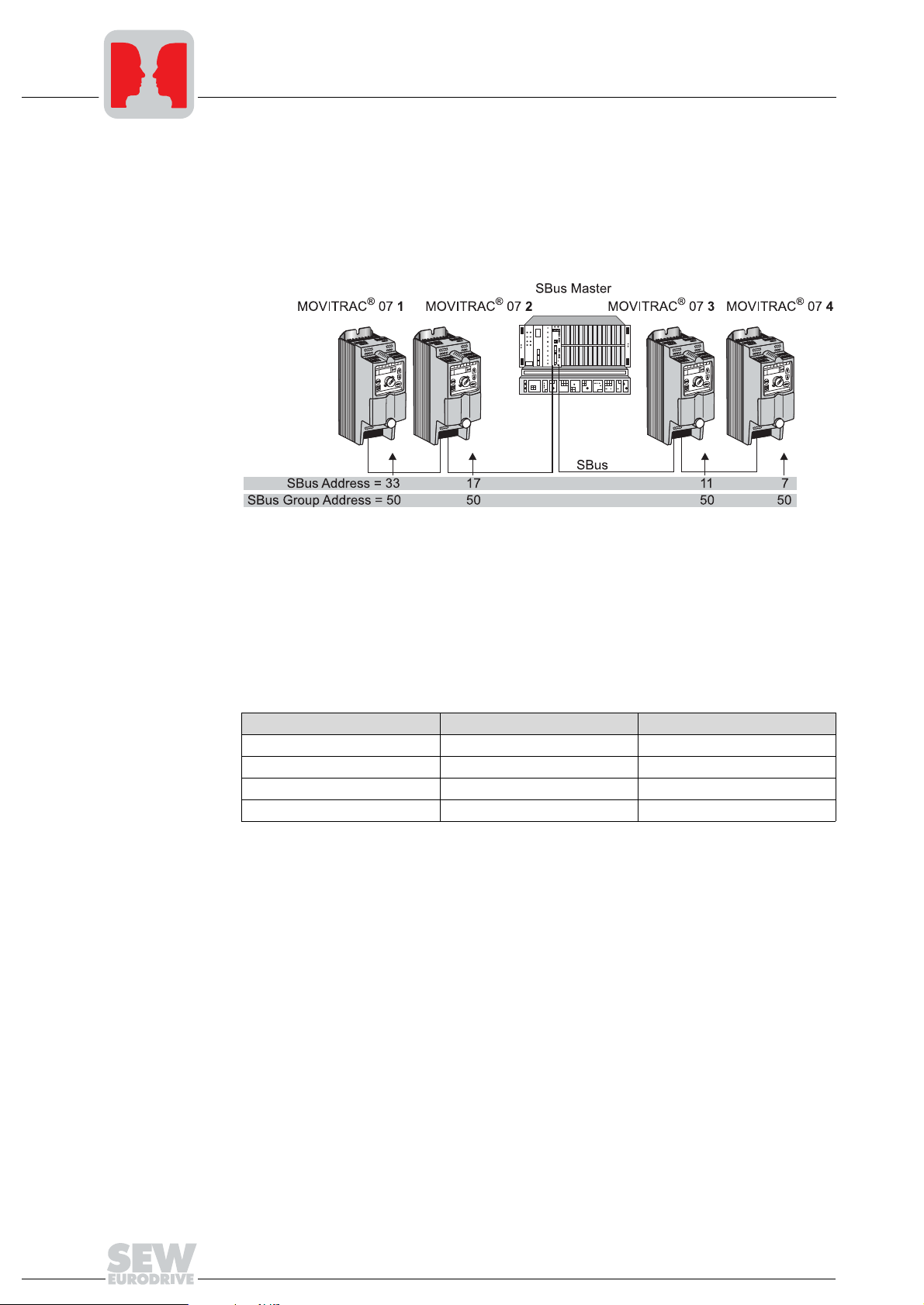
4.3 Project planning example for SBus
Specifications
Settings
The following settings have to be made:
• Four inverters
• Process data length 3
• Baud rate 500 kbit/s
05895AXX
Figure 10: Sample for project planning
Use parameter P816 to set the required SBus baud rate on all inverters. All inverters
must be set to the same baud rate. The factory setting for the baud rate is 500 kbaud.
The fixed setting for the number of process data on the SBus is "3 process data words."
Then use parameter P813 to set the SBus address on each inverter. In this example,
the SBus address is assigned to the inverters according to the following table:
Inverters SBus address SBus group address
1 33
2 17
3 11
4 7
dec
dec
dec
dec
50
50
50
50
dec
dec
dec
dec
You will realize that there is no prescribed sequence for setting of the SBus address. Do
not assign the addresses several times; two drive inverters must not share the same
SBus address.
In addition, the terminating resistor must also be switched on at the ends of the cable.
Do this by setting the S12 DIP switch on inverters 1 and 4 to ON. The terminating resistors must be switched off on all other stations, such as inverters 2 and 3 and the SBus
master control.
18
Manual – MOVITRAC® 07 Communication
 Loading...