

Page 1
Gearmotors \ Industrial Gear Units \ Drive Electronics \ Drive Automation \ Services
Fieldbus Interface DFP21B
PROFIBUS DP-V1
Edition 07/2006
11479019 / EN
M
FA375100
anual
Page 2

SEW-EURODRIVE – Driving the world
Phone: 800.894.0412 - Fax: 888.723.4773 - Web: www.clrwtr.com - Email: info@clrwtr.com
Page 3

1 Important Notes...................................................................................................... 6
Phone: 800.894.0412 - Fax: 888.723.4773 - Web: www.clrwtr.com - Email: info@clrwtr.com
1.1 Explanation of symbols .................................................................................. 6
1.2 Part of the product ......................................................................................... 6
1.3 Documentation reference............................................................................... 6
1.4 Liability for defects ......................................................................................... 7
1.5 Product names and trademarks..................................................................... 7
1.6 Disposal ......................................................................................................... 7
2 Safety Notes ........................................................................................................... 8
2.1 Preliminary information .................................................................................. 8
2.2 General safety notes...................................................................................... 8
2.2.1 General safety notes for bus systems.................................................. 8
2.3 Transport / storage......................................................................................... 8
2.4 Installation / assembly.................................................................................... 9
2.5 Startup / operation ......................................................................................... 9
3 Introduction .......................................................................................................... 10
3.1 Content of the manual.................................................................................. 10
3.2 Additional documentation............................................................................. 10
3.3 Features....................................................................................................... 10
3.3.1 MOVIDRIVE
®
, MOVITRAC® B and PROFIBUS................................ 10
3.3.2 Access to all information.................................................................... 11
3.3.3 Cyclical and acyclical data exchange via PROFIBUS DP ................. 11
3.3.4 Acyclical data exchange via PROFIBUSDP-V1................................. 11
3.3.5 Configuring the PROFIBUS option card ............................................ 12
3.3.6 Monitoring functions........................................................................... 12
3.3.7 Diagnostics ........................................................................................ 13
3.3.8 Fieldbus monitor ................................................................................ 13
4 Assembly and Installation Notes........................................................................14
4.1 Installing the DFP21B option card in MOVIDRIVE
®
MDX61B ..................... 14
4.1.1 Before you start ................................................................................. 14
4.1.2 Installing and removing an option card .............................................. 15
4.2 Installing the DFP21B option card in MOVITRAC
®
B .................................. 16
4.2.1 SBus connection................................................................................ 16
4.2.2 System bus connection...................................................................... 17
4.3 Assembling and installing the UOH11B gateway housing ........................... 18
4.4 Connection and terminal description of the DFP21B option ........................ 20
4.5 Pin assignment ............................................................................................ 21
4.5.1 MOVIDRIVE
®
/ MOVITRAC® B / PROFIBUS connection ................. 21
4.5.2 Baud rates greater than 1.5 MBaud................................................... 21
4.6 Shielding and routing bus cables ................................................................. 22
4.7 Bus termination ............................................................................................ 22
4.8 Setting the station address .......................................................................... 23
4.9 Operating mode displays: option DFP21B................................................... 24
4.9.1 PROFIBUS LEDs............................................................................... 24
Manual – Fieldbus Interface DFP21B PROFIBUS DP-V1
3
Page 4

5 Project Planning and Startup..............................................................................26
Phone: 800.894.0412 - Fax: 888.723.4773 - Web: www.clrwtr.com - Email: info@clrwtr.com
5.1 Validity of the GSD files for DFP21B............................................................ 26
5.2 DP master project planning the with MOVIDRIVE
®
GSD file....................... 26
5.2.1 GSD file for PROFIBUSDP................................................................ 26
5.2.2 GSD file for PROFIBUSDP-V1 .......................................................... 27
5.2.3 Project planning procedure................................................................ 28
5.2.4 DP configuration for MOVIDRIVE
5.2.5 MOVIDRIVE
®
MDX61B external diagnostics .................................... 32
5.3 DP master project planning with MOVITRAC
5.3.1 GSD files for operation in MOVITRAC
®
MDX61B (SEWA6003.GSD)...... 29
®
or gateway GSD file ........... 34
®
B and UOH11B gateway
housing .............................................................................................. 34
5.3.2 PROFIBUS DP master startup........................................................... 35
5.3.3 Configuration of the PROFIBUSDP interface .................................... 36
5.3.4 Autosetup for gateway operation ....................................................... 40
5.4 Setting the MOVIDRIVE
5.5 Setting the MOVITRAC
®
MDX61B drive inverter ....................................... 42
®
frequency inverter ................................................ 43
6 PROFIBUS DP Operating Characteristics ......................................................... 45
6.1 Controlling the MOVIDRIVE
6.1.1 Control example for SIMATIC S7 with MOVIDRIVE
6.1.2 PROFIBUS DP timeout (MOVIDRIVE
6.1.3 Fieldbus timeout response (MOVIDRIVE
6.2 Control of the MOVITRAC
6.2.1 Control example for SIMATIC S7 with MOVITRAC
®
MDX61B drive inverter ................................. 45
®
MDX61B)............................. 46
®
®
inverter (gateway)............................................ 47
MDX61B)........................ 46
®
MDX61B ........ 46
®
B (gateway)..... 48
6.2.2 SBus timeout ..................................................................................... 48
6.2.3 Unit faults........................................................................................... 48
6.2.4 Fieldbus timeout of the DFP21B in gateway operation...................... 49
6.3 Parameter settings via PROFIBUS DP........................................................ 49
6.3.1 Structure of the 8-byte MOVILINK
®
parameter channel .................... 49
6.3.2 Reading a parameter with PROFIBUS DP (READ)........................... 52
6.3.3 Writing a parameter via PROFIBUS DP (WRITE) ............................. 53
6.3.4 Parameter setting procedure with PROFIBUS DP............................. 54
6.3.5 Parameter data format....................................................................... 54
6.4 SIMATIC STEP7 program example ............................................................. 55
6.5 Return codes for parameter setting.............................................................. 56
6.5.1 Elements............................................................................................ 56
6.5.2 Error class.......................................................................................... 56
6.5.3 Error code .......................................................................................... 56
6.5.4 Additional code .................................................................................. 57
6.6 Special cases............................................................................................... 57
6.6.1 Special return codes .......................................................................... 57
4
Manual – Fieldbus Interface DFP21B PROFIBUS DP-V1
Page 5

7 PROFIBUS DP-V1 Functions............................................................................... 59
Phone: 800.894.0412 - Fax: 888.723.4773 - Web: www.clrwtr.com - Email: info@clrwtr.com
7.1 Introduction to PROFIBUS DP-V1 ............................................................... 59
7.1.1 Class 1 master (C1 master)............................................................... 60
7.1.2 Class 2 master (C2 master)............................................................... 60
7.1.3 Data sets (DS) ................................................................................... 60
7.1.4 DP-V1 services .................................................................................. 61
7.1.5 DP-V1 alarm handling........................................................................ 61
7.2 Features of SEW drive inverters .................................................................. 62
7.3 Structure of the DP-V1 parameter channel.................................................. 63
7.3.1 Parameter setting procedure via data set 47..................................... 65
7.3.2 DP-V1 master processing sequence ................................................. 66
7.3.3 Addressing connected drive inverters................................................ 67
7.3.4 MOVILINK
®
parameter requests ....................................................... 67
7.3.5 PROFIdrive parameter requests........................................................ 72
7.4 Project planning for a C1 master.................................................................. 77
7.4.1 Operating mode (DP-V1 mode) ......................................................... 77
7.4.2 Example program for SIMATIC S7 .................................................... 78
7.4.3 DP-V1 technical data for MOVIDRIVE
7.4.4 Technical data DP-V1 for the gateway operation and MOVITRAC
®
DFP21 ................................ 83
®
.83
7.4.5 Error codes of the DP-V1 services..................................................... 84
8 Operation of MOVITOOLS
®
MotionStudio via PROFIBUS................................ 85
8.1 Introduction .................................................................................................. 85
8.2 Required hardware ...................................................................................... 86
8.3 Required software........................................................................................ 86
8.4 Installation.................................................................................................... 86
8.5 Configuring SIMATIC NET........................................................................... 87
8.6 Configuration of SEW communication server .............................................. 90
8.6.1 Establishing communication .............................................................. 90
8.6.2 Procedure .......................................................................................... 90
8.7 Automatic search for connected units (unit scan) ....................................... 93
8.8 Activating online operation........................................................................... 93
8.9 Known problems when operating MOVITOOLS
®
MotionStudio .................. 94
9 Error Diagnostics................................................................................................. 95
9.1 Diagnostic procedures ................................................................................. 95
9.2 List of errors ................................................................................................. 98
10 Technical Data...................................................................................................... 99
10.1 Option DFP21B for MOVIDRIVE
10.2 DFP21B option for MOVITRAC
®
MDX61B ................................................ 99
®
B and UOH11B gateway housing.......... 100
11 Index.................................................................................................................... 101
Manual – Fieldbus Interface DFP21B PROFIBUS DP-V1
5
Page 6
1
Phone: 800.894.0412 - Fax: 888.723.4773 - Web: www.clrwtr.com - Email: info@clrwtr.com
Important Notes
Explanation of symbols
1 Important Notes
Manual
1.1 Explanation of symbols
Always follow the safety and warning notes in this publication.
Electrical hazard
Possible consequences: Severe or fatal injuries
Hazard
Possible consequences: Severe or fatal injuries
Hazardous situation
Possible consequences: Slight or minor injuries
Harmful situation
Possible consequences: Damage to the unit and the
environment
Tips and useful information
1.2 Part of the product
The manual is a component of the DFP21B PROFIBUSDP-V1 fieldbus interface and
contains important information for operation and service.
1.3 Documentation reference
• You must adhere to the information in the documentation to ensure:
• Fault-free operation
• Fulfillment of any rights to claim under limited warranty
• Consequently, read through this manual carefully before you start installation and
startup of the frequency inverters with the DFP21B PROFIBUS option card.
• This manual assumes that the user has access to and is familiar with the
MOVIDRIVE
MDX60B/61B und MOVITRAC® B system manuals.
®
and MOVITRAC® documentation, in particular the MOVIDRIVE
®
6
Manual – DFP21B PROFIBUSDP-V1 Fieldbus Interface
Page 7

1.4 Liability for defects
Phone: 800.894.0412 - Fax: 888.723.4773 - Web: www.clrwtr.com - Email: info@clrwtr.com
Incorrect handling or undertaking any action that is not specified in this manual could
impair the properties of the product. If this is the case, you lose any right to claim against
SEW-EURODRIVE GmbH & Co KG under limited warranty.
1.5 Product names and trademarks
The brands and product names named in these operating instructions are trademarks
or registered trademarks of the titleholders.
1.6 Disposal
Please follow the current national regulations.
Dispose of the following materials separately in accordance with the country-specific
regulations in force, as:
• Electronic scrap
• Plastics
• Sheet metal
• Copper
and so on
Important Notes
Liability for defects
1
Manual – DFP21B PROFIBUSDP-V1 Fieldbus Interface
7
Page 8
2
Phone: 800.894.0412 - Fax: 888.723.4773 - Web: www.clrwtr.com - Email: info@clrwtr.com
Safety Notes
Preliminary information
2 Safety Notes
• You are only allowed to perform installation and startup of the DFP21B field-
2.1 Preliminary information
The following safety notes apply to the fieldbus interface DFP21B PROFIBUS DPV1.
Please also consider the supplementary safety notes in the individual sections of
this manual.
bus interface when observing applicable accident prevention regulations and
the MOVIDRIVE
®
MDX60B/61B and MOVITRAC® B operating instructions.
2.2 General safety notes
Never install or start up damaged products.
Submit a complaint to the shipping company immediately in the event of damage.
2.2.1 General safety notes for bus systems
This communication system allows you to adjust the MOVIDRIVE® drive inverter to your
specific application very accurately. As with all bus systems, there is a danger of
modifications to the parameters that are not visible from outside (in relation to the
inverter), which give rise to changes in the inverter behavior. This may result in
unexpected (not uncontrolled) system behavior.
2.3 Transport / storage
Inspect the shipment as soon as you receive the delivery and inform the shipping
company of any damage that may have occurred in transit immediately. Do not
operate the product if it is damaged.
Use suitable, sufficiently rated handling equipment if necessary.
Damage can result from incorrect storage.
Store the unit in a dry, dust-free room if it is not to be installed straight away.
8
Manual – DFP21B PROFIBUSDP-V1 Fieldbus Interface
Page 9

2.4 Installation / assembly
Phone: 800.894.0412 - Fax: 888.723.4773 - Web: www.clrwtr.com - Email: info@clrwtr.com
Adhere to the instructions in section 4, "Assembly and Installation Notes".
2.5 Startup / operation
Adhere to the instructions in section 5, "Project Planning and Startup".
Safety Notes
Installation / assembly
2
Manual – DFP21B PROFIBUSDP-V1 Fieldbus Interface
9
Page 10

3
Phone: 800.894.0412 - Fax: 888.723.4773 - Web: www.clrwtr.com - Email: info@clrwtr.com
Introduction
Content of the manual
3 Introduction
3.1 Content of the manual
This user manual describes how to:
• Install the PROFIBUS DFP21B option card in the MOVIDRIVE
inverter
• Use the PROFIBUS DFP21B option card in the MOVIDRIVE
and in the UOH11B gateway housing
• Start up the MOVIDRIVE
• Start up the MOVITRAC
• Configure the PROFIBUS using GSD files
• Operate MOVITOOLS
3.2 Additional documentation
®
B with the PROFIBUS fieldbus system
®
B with the PROFIBUS gateway
®
MotionStudio via PROFIBUS
®
MDX61B drive
®
B frequency inverter
3.3 Features
3.3.1 MOVIDRIVE
For information on how to connect MOVIDRIVE® straightforwardly and effectively to the
PROFIBUS fieldbus system, in addition to this user manual about the PROFIBUS
option, you should request the following publications about fieldbus technology:
•MOVIDRIVE
•MOVITRAC
The manual for the MOVIDRIVE
manual describes the fieldbus parameters and their coding, and explains the whole
range of various control concepts and application options in the form of brief examples.
The MOVIDRIVE
the drive inverter which can be read and written via the various communication
interfaces, such as system bus, RS-485 and also via the fieldbus interface.
The MOVIDRIVE® MDX61B drive inverter and MOVITRAC® B frequency inverter allow
you to use the DFP21B option to connect to higher-level automation systems via PROFIBUS thanks to its powerful universal fieldbus interface.
®
, MOVITRAC® B and PROFIBUS
®
Fieldbus Unit Profile manual
®
B system manual
®
Fieldbus Unit Profile and MOVITRAC® B system
®
"Fieldbus Unit Profile" manual contains a listing of all parameters of
The unit behavior of the inverter, which forms the basis of PROFIBUS operation, is
referred to as the unit profile. It is independent of any particular fieldbus and is therefore
a uniform feature. This feature allows the user to develop fieldbus-independent drive
applications. This makes it much easier to change to other bus systems, such as
DeviceNet (option DFD).
10
Manual – DFP21B PROFIBUSDP-V1 Fieldbus Interface
Page 11

3.3.2 Access to all information
Phone: 800.894.0412 - Fax: 888.723.4773 - Web: www.clrwtr.com - Email: info@clrwtr.com
®
MOVIDRIVE
the PROFIBUS interface. The drive inverter is controlled via fast, cyclic process data.
Via this process data channel, you can enter setpoints such as the setpoint speed, ramp
generator time for acceleration/deceleration, etc. as well as trigger various drive
functions such as enable, control inhibit, normal stop, rapid stop, etc. However, at the
same time you can also use this channel to read back actual values from the drive
inverter, such as the actual speed, current, unit status, fault number and reference
signals.
3.3.3 Cyclical and acyclical data exchange via PROFIBUS DP
While process data exchange usually takes place cyclically, drive parameters can be
read and written acyclically via functions such as READ or WRITE or via the
MOVILINK
implement applications in which all the important drive parameters are stored in the
master programmable controller, so that there is no need to make parameter settings
manually on the drive inverter itself.
MDX61B offers digital access to all drive parameters and functions via
®
parameter channel. This parameter data exchange enables you to
Introduction
Features
3
3.3.4 Acyclical data exchange via PROFIBUS DP-V1
The PROFIBUS DP-V1 specification introduced new acyclical READ/WRITE services
as part of the PROFIBUSDP expansions. These acyclical services are added to the current cyclical bus operation in special telegrams to ensure compatibility of PROFIBUS DP
and PROFIBUS DP V1.
Manual – DFP21B PROFIBUSDP-V1 Fieldbus Interface
11
Page 12
3
EURODRIVE
Phone: 800.894.0412 - Fax: 888.723.4773 - Web: www.clrwtr.com - Email: info@clrwtr.com
Introduction
Features
3.3.5 Configuring the PROFIBUS option card
Generally, the PROFIBUS option card has been designed so that all fieldbus-specific
settings, such as the station address and the default bus parameter can be made using
hardware switches on the option card. This manual setting means the drive inverter can
be integrated into the PROFIBUS environment and switched on within a very short
period of time.
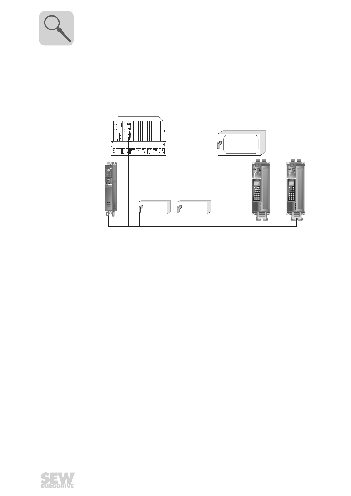
[1]
PROFIBUS Master
B
®
EURODRIVEEURODRIVE
MOVITRAC
Figure 1: PROFIBUS with MOVIDRIVE
[1] Visualization
3.3.6 Monitoring functions
Using a fieldbus system demands additional monitoring functions in the drive engineering, for example, time monitoring of the fieldbus (fieldbus timeout) or rapid stop
concepts. For example, you can adapt MOVIDRIVE
specifically to your application. You can determine, for instance, which of the drive
inverter's fault responses should be triggered in the event of a bus error. A rapid stop is
a good idea for many applications, although this can also be achieved by "freezing" the
last setpoints so the drive continues operating with the most recently valid setpoints
(such as with a conveyor belt). As the control terminals also function in fieldbus operation, you can still implement fieldbus-independent emergency stop concepts via the
terminals of the drive inverter.
Digital I/O Analog I/O
PROFIBUS
®
B
®
MOVIDRIVE
®
/MOVITRAC® monitoring functions
B
®
MOVIDRIVE
58687AXX
12
Manual – DFP21B PROFIBUSDP-V1 Fieldbus Interface
Page 13

3.3.7 Diagnostics
Phone: 800.894.0412 - Fax: 888.723.4773 - Web: www.clrwtr.com - Email: info@clrwtr.com
The MOVIDRIVE
numerous diagnostics options for startup and service. For example, you can use the
integrated fieldbus monitor to control setpoint values sent from the higher-level control
as well as the actual values.
3.3.8 Fieldbus monitor
Furthermore, you are supplied with a variety of additional information about the status
of the fieldbus option card. The fieldbus monitor function in conjunction with the
MOVITOOLS
setting all drive parameters (including the fieldbus parameters) and for displaying the
fieldbus and device status information in detail.
Introduction
Features
®
drive inverter and the MOVITRAC® B frequency inverter offer you
®
MotionStudio PC software offers you an easy-to-use diagnostic tool for
3
Manual – DFP21B PROFIBUSDP-V1 Fieldbus Interface
13
Page 14

4
Phone: 800.894.0412 - Fax: 888.723.4773 - Web: www.clrwtr.com - Email: info@clrwtr.com
Assembly and Installation Notes
Installing the DFP21B option card in MOVIDRIVE® MDX61B
4 Assembly and Installation Notes
This section contains information about assembly and installation of the DFP21B option
card in the MOVIDRIVE
®
MDX61B, MOVITRAC® B and UOH11B gateway housing.
4.1 Installing the DFP21B option card in MOVIDRIVE® MDX61B
Only SEW-EURODRIVE engineers are allowed to install or remove option cards
for MOVIDRIVE
• Option cards can only be installed or removed by users for MOVIDRIVE
MDX61B sizes 1 to 6.
4.1.1 Before you start
The DFP21B option card must be plugged into the fieldbus slot.
Observe the following notes before installing or removing an option card:
• Disconnect the inverter from the power. Switch off the DC 24 V and the supply
voltage.
• Take appropriate measures to protect the option card from electrostatic charge (use
discharge strap, conductive shoes, and so on) before touching it.
• Before installing the option card, remove the keypad and the front cover.
• After installing the option card, replace the keypad and the front cover.
• Keep the option card in its original packaging until immediately before you are ready
to install it.
• Hold the option card by its edges only. Do not touch any components.
®
MDX61B size 0.
®
14
Manual – DFP21B PROFIBUSDP-V1 Fieldbus Interface
Page 15
Installing the DFP21B option card in MOVIDRIVE® MDX61B
Phone: 800.894.0412 - Fax: 888.723.4773 - Web: www.clrwtr.com - Email: info@clrwtr.com
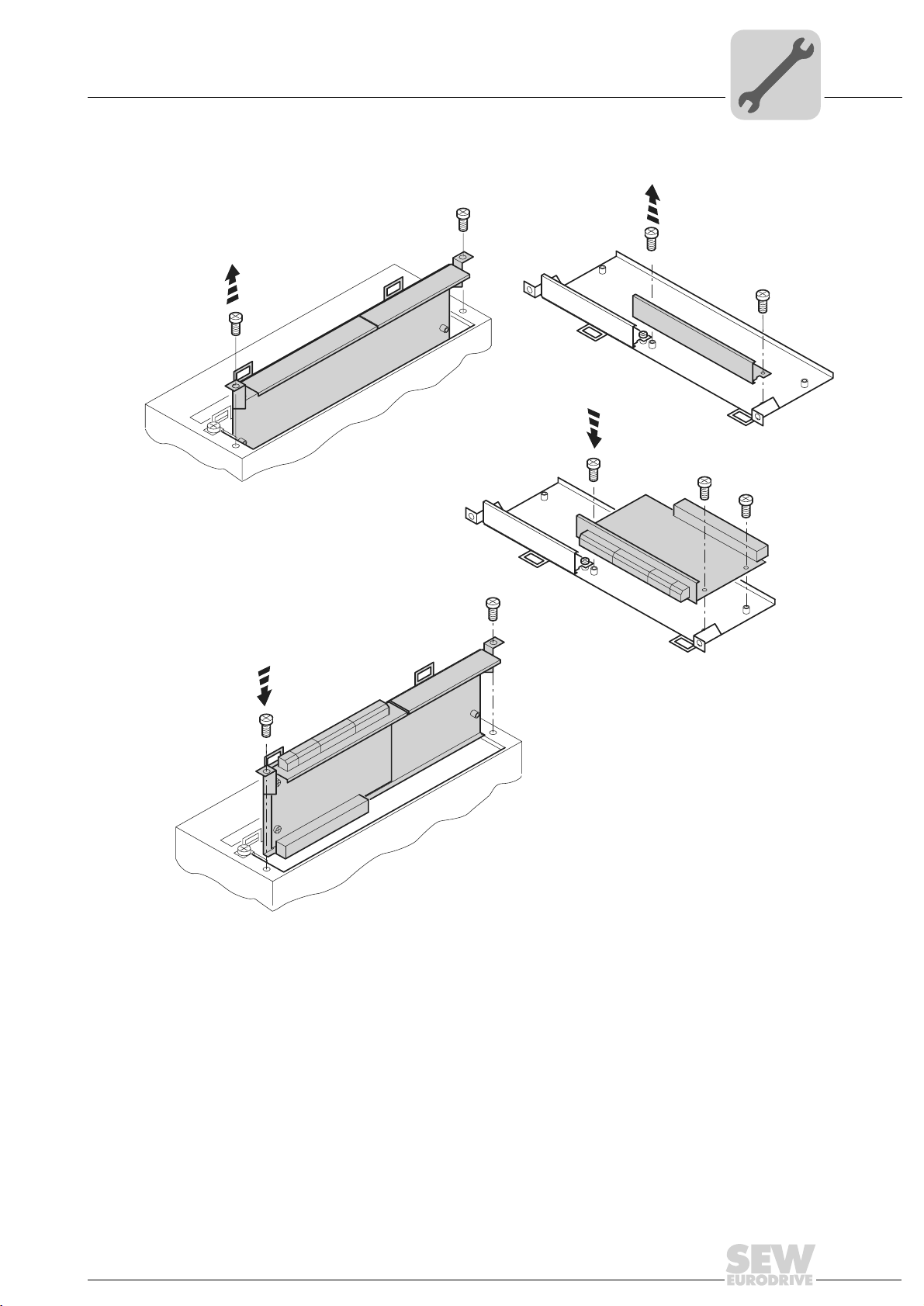
4.1.2 Installing and removing an option card
1.
Assembly and Installation Notes
2.
3.
4
4.
Figure 2: Installing an option card in MOVIDRIVE® MDX61B sizes 1 to 6
1. Remove the two retaining screws holding the card retaining bracket. Pull the card
retaining bracket out evenly from the slot (do not twist!).
2. Remove the two retaining screws of the black cover plate on the card retaining
bracket. Remove the black cover plate.
3. Position the option card onto the retaining bracket so that the three retaining screws
fit into the corresponding bores on the card retaining bracket.
4. Insert the retaining bracket with installed option card into the slot, pressing slightly so
it is seated properly. Secure the card retaining bracket with the two retaining screws.
5. To remove the option card, follow the instructions in reverse order.
53001AXX
Manual – DFP21B PROFIBUSDP-V1 Fieldbus Interface
15
Page 16
4
Phone: 800.894.0412 - Fax: 888.723.4773 - Web: www.clrwtr.com - Email: info@clrwtr.com
Assembly and Installation Notes
Installing the DFP21B option card in MOVITRAC® B
4.2 Installing the DFP21B option card in MOVITRAC® B
•MOVITRAC® B does not require special firmware status.
• Only SEW-EURODRIVE engineers are allowed to install or remove option cards for
MOVITRAC
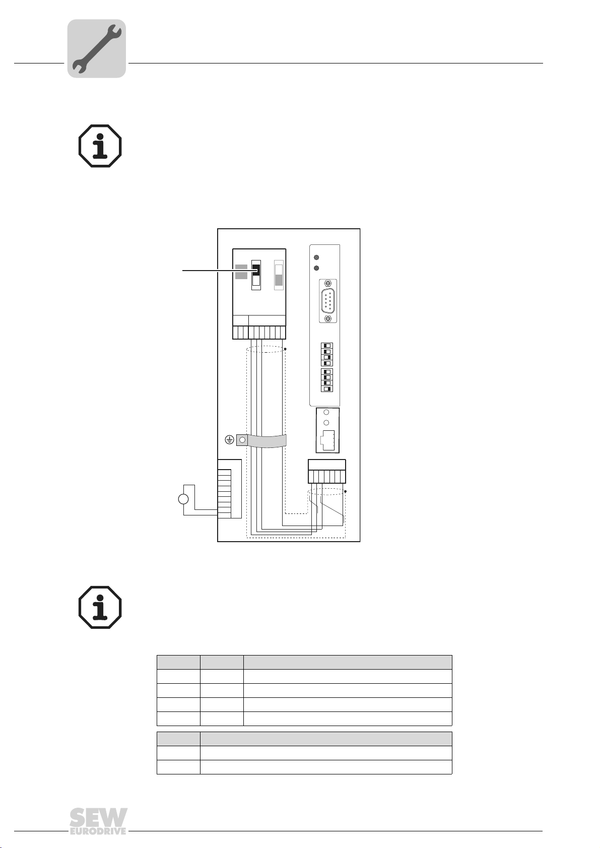
4.2.1 SBus connection
[1]
®
B.
X44
X45
S1
FSC11B
X46
23456HL ⊥
1
MOVITRAC® B
S2
ON
OFF
7
DFP21B
RUN
BUS
FAULT
9
6
X30
01
0
2
1
2
2
2
3
2
4
2
5
2
6
2
AS
ADDRESS
X24
5
1
H1
H2
24V
X12
1
2
3
+
=
24V IO
–
GND
4
5
6
7
8
9
X26
1234567
59185AXX
[1] Terminating resistor activated, S1 = ON
The DFP21B features an integrated SBus terminating resistor and must therefore
always be installed at the beginning of the SBus connection.
The address of the DFP21B is always 0.
X46 X26
X46:1 X26:1 SC11 SBus +, CAN high
X46:2 X26:2 SC12 SBus , CAN low
X46:3 X26:3 GND, CAN GND
X46:7 X26:7 DC 24 V
X12
X12:8 +24-V input
X12:9 GND reference potential for the binary inputs
16
Manual – DFP21B PROFIBUSDP-V1 Fieldbus Interface
Page 17
Assembly and Installation Notes
Phone: 800.894.0412 - Fax: 888.723.4773 - Web: www.clrwtr.com - Email: info@clrwtr.com
Installing the DFP21B option card in MOVITRAC® B
4
To simplify cabling, the DFP21B can be supplied with DC 24V from X46.7 of the
MOVITRAC
MOVITRAC
ing the DFP21B by MOVITRAC
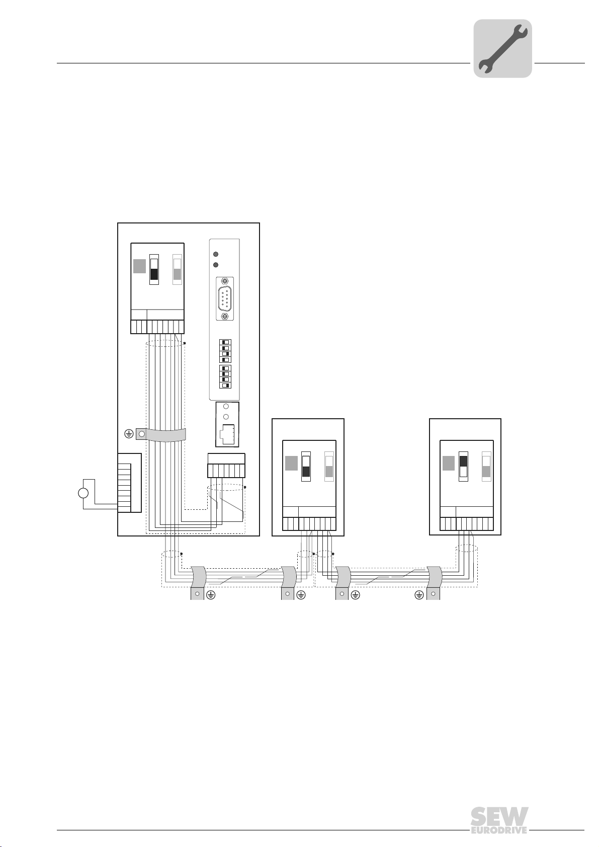
4.2.2 System bus connection
MOVITRAC® B
S1
S2
ON
OFF
X44
FSC11B
X46
X45
7
23456HL^
1
X12
1
2
3
4
5
6
7
8
9
24V
+
=
-
24V IO
GND
®
to X26.7.
®
must be supplied with DC 24V at terminals X12.8 and X12.9 when supply-
DFP21B
RUN
BUS
FAULT
5
9
6
1
X30
01
0
2
1
2
2
2
3
2
4
2
5
2
6
2
AS
ADDRESS
H1
H2
X24
X26
1234567
®
.
MOVITRAC® B
S1
ON
OFF
X44
FSC11B
X46
X45
23456HL ^
1
S2
MOVITRAC® B
S1
S2
ON
OFF
X44
FSC11B
X46
X45
7
23456HL ^
1
7
Figure 3: System bus connection
DFP
GND = System bus reference
SC11 = System bus high
SC12 = System bus low
MOVITRAC® B
GND = System bus reference
SC22 = System bus low, outgoing
SC21 = System bus high, outgoing
SC12 = System bus low, incoming
SC11 = System bus high, incoming
S12 = System bus terminating resistor
Manual – DFP21B PROFIBUSDP-V1 Fieldbus Interface
59186AXX
17
Page 18

4
Phone: 800.894.0412 - Fax: 888.723.4773 - Web: www.clrwtr.com - Email: info@clrwtr.com
Assembly and Installation Notes
Installing the DFP21B option card in MOVITRAC® B
Note:
• Use a two-core twisted and shielded copper cable (data transmission cable with
braided copper shield). Connect the shield flatly on both sides of the electronics
shield clamp of MOVITRAC
must meet the following specifications:
– Core cross-section 0.75 mm
– Line resistance 120 Ω at 1 MHz
– Capacitance per unit length ≤ 40 pF/m (12 pF/ft) at 1 kHz
• The permitted total cable length depends on the baud rate setting of the SBus:
– 250 kbaud: 160 m (528 ft)
– 500 kbaud: 80 m (264 ft)
– 1000 kbaud: 40 m (132 ft)
• Connect the system bus terminating resistor (S1 = ON) at the end of the system bus
connection. Switch off the terminating resistor on the other units (S1 = OFF). The
DFP21B gateway must always be connected either at the beginning or the end of the
system bus connection and features a permanently installed terminating resistor.
®
. Also connect the ends of the shield to GND. The cable
2
(AWG18)
• There must not be any potential displacement between the units connected with the
SBus. Take suitable measures to avoid potential displacement, such as connecting
the unit ground connectors using a separate cable.
• Point-to-point wiring is not permitted.
18
Manual – DFP21B PROFIBUSDP-V1 Fieldbus Interface
Page 19
Assembly and Installation Notes
V
Phone: 800.894.0412 - Fax: 888.723.4773 - Web: www.clrwtr.com - Email: info@clrwtr.com
Assembling and installing the UOH11B gateway housing
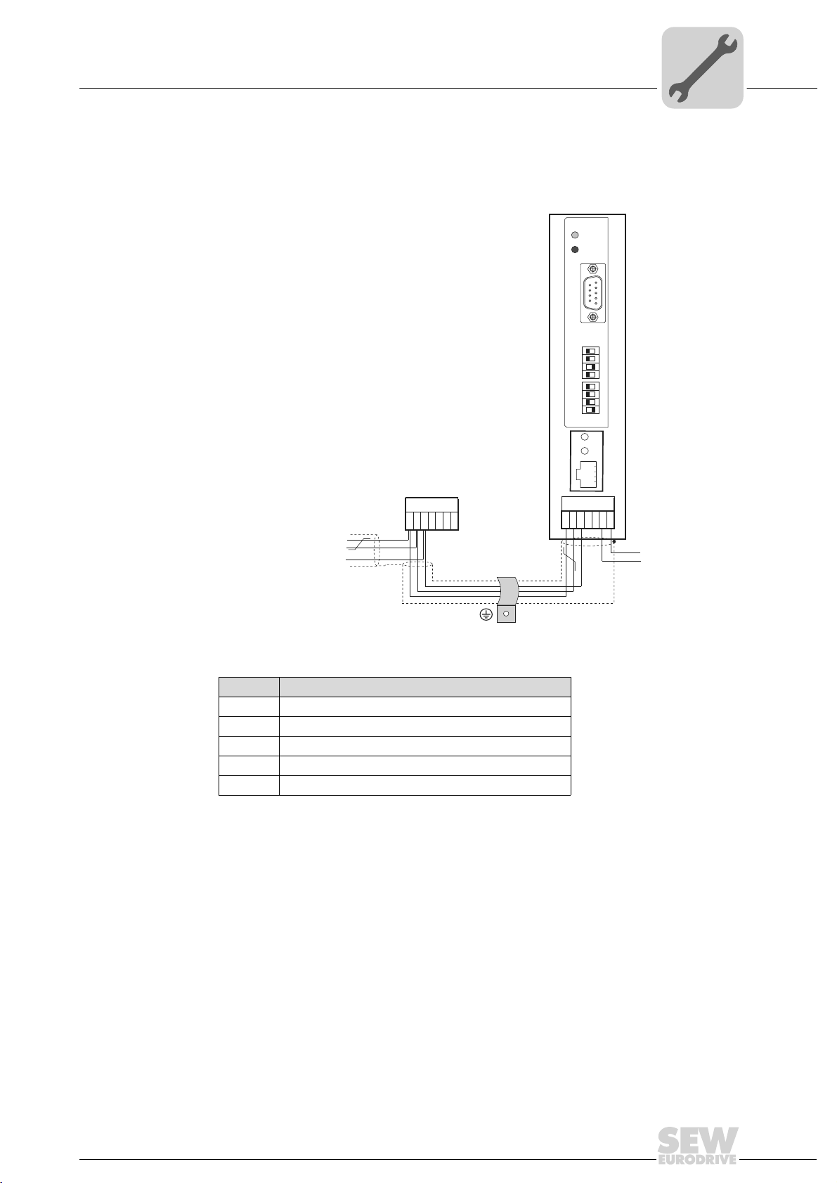
4.3 Assembling and installing the UOH11B gateway housing
UOH11B
DFP21B
2
2
2
2
2
2
2
AS
ADDRESS
SEW Drive
23456
1
SC11 Systembus +, CAN high
SC12 Systembus -, CAN low
GND, CAN GND
RUN
BUS
FAULT
0
1
2
3
4
5
6
X24
X26
9
6
X30
01
4
5
1
H1
H2
7
+ 24
GND
58121BXX
X26
X26:1 SC11 system bus +, CAN high
X26:2 SC12 system bus, CAN low
X26:3 GND, CAN GND
X26:6 GND, CAN GND
X26:7 DC 24 V
The gateway housing has a power supply of DC 24V that is connected to X26.
Manual – DFP21B PROFIBUSDP-V1 Fieldbus Interface
19
Page 20
4
Phone: 800.894.0412 - Fax: 888.723.4773 - Web: www.clrwtr.com - Email: info@clrwtr.com
Assembly and Installation Notes
Connection and terminal description of the DFP21B option
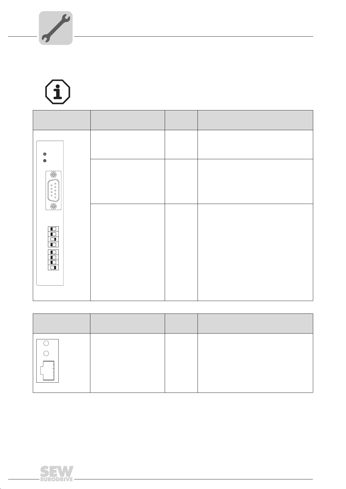
4.4 Connection and terminal description of the DFP21B option
Part number
PROFIBUS interface type DFP21B option: 824 240 2
The "PROFIBUS interface type DFP21B" option is only possible in conjunction with
MOVIDRIVE
The DFP21B option must be plugged into the fieldbus slot.
Front view of DFP21B Description
RUN: PROFIBUS operation
LED (green)
DFP21B
RUN
BUS
FAULT
5
9
6
1
X30
01
0
2
1
2
2
2
3
2
4
2
5
2
6
2
AS
ADDRESS
BUS FAULT: PROFIBUS error
LED (red)
ADDRESS: DIP switch for setting the PROFIBUS station
address
X30: PROFIBUS connection X30:1
®
MDX61B, not with MDX60B.
DIP
switches
Terminal
0
2
1
2
2
2
3
2
4
2
5
2
6
2
AS
X30:2
X30:3
X30:4
X30:5
X30:6
X30:7
X30:8
X30:9
Function
Indicates that the bus electronics are operating
correctly.
Indicates PROFIBUSDP error.
Significance: 1
Significance: 2
Significance: 4
Significance: 8
Significance: 16
Significance: 32
Significance: 64
Autosetup for gateway operation
N.C.
N.C.
RxD/TxD-P
CNTR-P
DGND (M5V)
VP (P5V/100 mA)
N.C.
RxD/TxD-N
DGND (M5V)
Front view of
MOVITRAC
®
and UOH11B
H1
H2
X24
59110AXX
B, DFP21B
58129axx
Description Function
LED H1 (red)
LED H2 (green)
X24 X terminal
System error (only for gateway functions)
Reserved
RS-485 interface for diagnostics via PC and
MOVITOOLS
(only applies to MOVITRAC
®
MotionStudio
®
B)
20
Manual – DFP21B PROFIBUSDP-V1 Fieldbus Interface
Page 21

4.5 Pin assignment
Phone: 800.894.0412 - Fax: 888.723.4773 - Web: www.clrwtr.com - Email: info@clrwtr.com
Connection to the PROFIBUS network using a 9-pin sub D plug according to IEC 61158.
The T-bus connection must be made using a connector with the corresponding configuration.
6
9
Figure 4: Assignment of 9-pin sub D plug to IEC 61158
[1] 9-pin sub-D connector
[2] Signal line, twisted
[3] Conductive, wide area connection is necessary between the connector housing and the shield
[1]
RxD/TxD-P
1
RxD/TxD-N
CNTR-P
DGND (M5V)
VP (P5V/100mA)
5
DGND (M5V)
Assembly and Installation Notes
Pin assignment
[2]
3
8
4
5
6
9
[3]
4
06227AXX
4.5.1 MOVIDRIVE
®
/ MOVITRAC® B / PROFIBUS connection
As a rule, the DFP21B option is connected to the PROFIBUS system using a shielded
twisted-pair cable. Observe the maximum supported transmission rate when selecting
the bus connector.
The twisted-pair cable is connected to the PROFIBUS connector at pin 3 (RxD/TxD-P)
and pin 8 (RxD/TxD-N). Communication takes place via these two contacts. The RS-485
signals RxD/TxD-P and RxD/TxD-N must be connected to the same contacts in all
PROFIBUS stations. Otherwise, no communication is possible via the bus medium.
The PROFIBUS interface sends a TTL control signal for a repeater or fiber optic adapter
(reference = pin 9) via pin 4 (CNTR-P).
4.5.2 Baud rates greater than 1.5 MBaud
The DFP21B option with baud rates > 1.5 MBaud can only be operated with special 12MBaud PROFIBUS connectors.
Manual – DFP21B PROFIBUSDP-V1 Fieldbus Interface
21
Page 22

4
Phone: 800.894.0412 - Fax: 888.723.4773 - Web: www.clrwtr.com - Email: info@clrwtr.com
Assembly and Installation Notes
Shielding and routing bus cables
4.6 Shielding and routing bus cables
The PROFIBUS interface supports RS-485 transmission technology and requires the
cable type A to IEC 61158 as the physical medium for the PROFIBUS. This cable must
be a shielded, twisted-pair cable.
Correct shielding of the bus cable attenuates electrical interference that may occur in
industrial environments. The following measures ensure the best possible shielding:
• Manually tighten the mounting screws on the connectors, modules, and equipotential
bonding conductors.
• Use only connectors with a metal housing or a metallized housing.
• Connect the shielding in the connector over a wide surface area.
• Apply the shielding of the bus line on both ends.
• Route signal and bus cables in separate cable ducts. Do not route them parallel to
power cables (motor leads).
• In industrial environments, use metallic, grounded cable racks.
• Route the signal cable and the corresponding equipotential bonding close to each
other using the shortest possible route.
• Avoid using plug connectors to extend bus cables.
• Route the bus cables closely along existing grounding surfaces.
In case of fluctuations in the ground potential, a compensating current may flow via the
bilaterally connected shield that is also connected to the protective earth (PE). In this
case, make adequate provision for equipotential bonding in accordance with the
relevant VDE regulations.
4.7 Bus termination
The DFP21B option is not provided with bus terminating resistors. This enables the bus
system to be put into operation more easily and reduces the number of error sources.
Use a plug with an integrated bus terminating resistor if the DFP21B option is at the
beginning or end of a PROFIBUS segment and only one PROFIBUS cable is leading to
the DFP21B.
Switch on the bus terminating resistors for this PROFIBUS connector.
22
Manual – DFP21B PROFIBUSDP-V1 Fieldbus Interface
Page 23
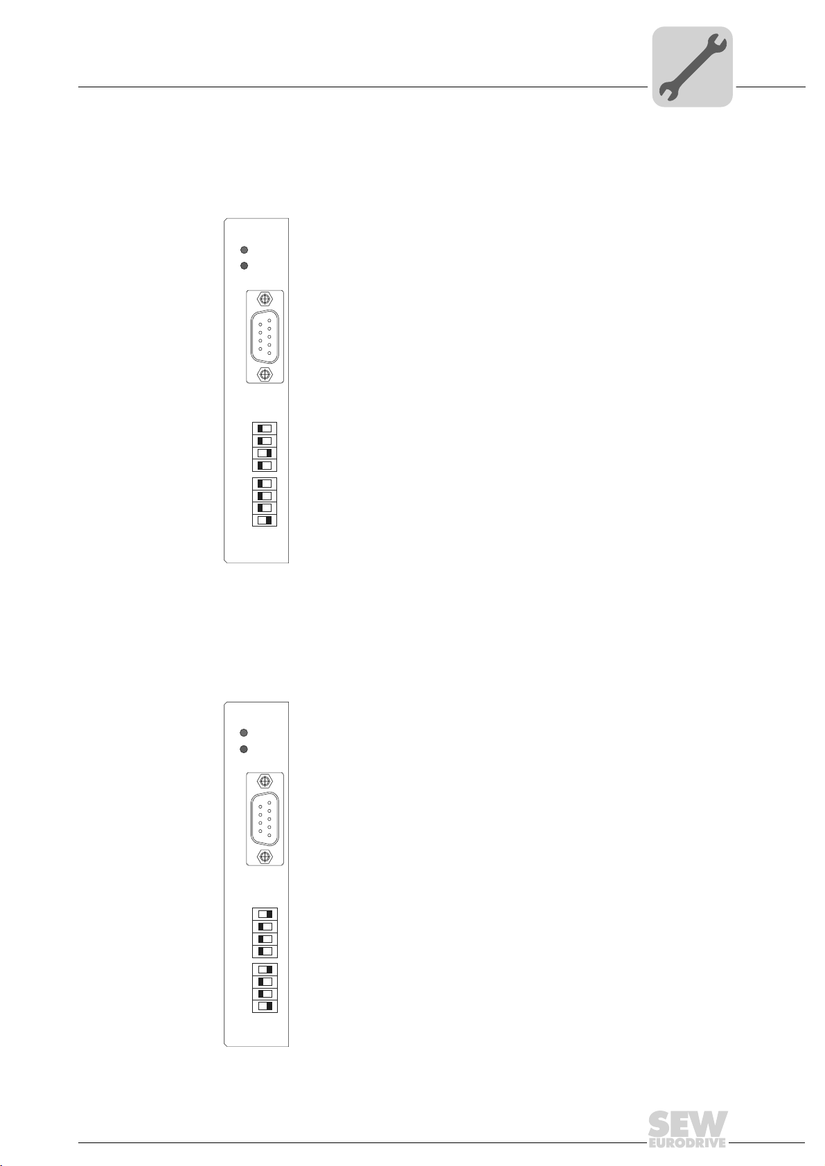
4.8 Setting the station address
Phone: 800.894.0412 - Fax: 888.723.4773 - Web: www.clrwtr.com - Email: info@clrwtr.com
Assembly and Installation Notes
Setting the station address
4
The PROFIBUS station address is set using DIP switches 20 to 26 on the option card.
MOVIDRIVE
®
supports the address range 1 to 125.
The default setting for the PROFIBUS station address is 4:
DFP21B
RUN
BUS
FAULT
5
9
6
1
X30
01
0
2
1
2
2
2
3
2
4
2
5
2
6
2
AS
ADDRESS
0
→ Significance: 1 × 0 = 0
2
1
2
→ Significance: 2 × 0 = 0
2
2
→ Significance: 4 × 1 = 4
3
2
→ Significance: 8 × 0 = 0
4
2
→ Significance: 16 × 0 = 0
5
2
→ Significance: 32 × 0 = 0
6
2
→ Significance: 64 × 0 = 0
59110AXX
Any change made to the PROFIBUS station address during ongoing operation does not
take effect immediately. The change only comes into effect when the inverter is switched
on again (power supply + 24 V OFF/ON). The inverter displays the current station
address in fieldbus monitor parameter P092 "Fieldbus address" (display with DBG60B
or MOVITOOLS
DFP21B
RUN
BUS
FAULT
5
9
6
1
X30
01
0
2
1
2
2
2
3
2
4
2
5
2
6
2
AS
ADDRESS
®
/SHELL).
Example: Setting the PROFIBUS station address 17
0
→ Significance: 1 × 1 = 1
2
1
2
→ Significance: 2 × 0 = 0
2
2
→ Significance: 4 × 0 = 0
3
→ Significance: 8 × 0 = 0
2
4
2
→ Significance: 16 × 1 = 16
5
2
→ Significance: 32 × 0 = 0
6
→ Significance: 64 × 0 = 0
2
59111AXX
Manual – DFP21B PROFIBUSDP-V1 Fieldbus Interface
23
Page 24
4
Phone: 800.894.0412 - Fax: 888.723.4773 - Web: www.clrwtr.com - Email: info@clrwtr.com
Assembly and Installation Notes
Operating mode displays: option DFP21B
4.9 Operating mode displays: option DFP21B
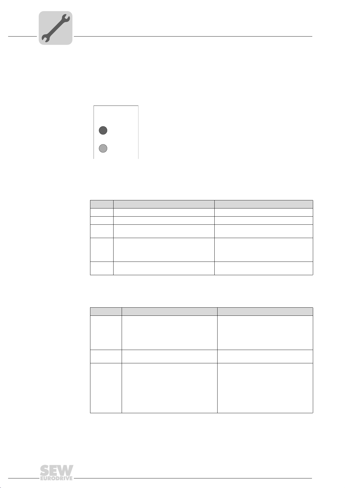
4.9.1 PROFIBUS LEDs
The PROFIBUS interface DFP21B option card has 2 LEDs that indicate the current
status of the DFP21B option and the PROFIBUS system.
DFP21B
RUN
BUS
FAULT
58361AXX
RUN LED (green)
LED BUS FAULT
(red)
• The RUN LED (green) indicates that the bus electronics are operating correctly
RUN Cause of error Remedy
Green • PROFIBUS hardware OK. –
Orange • The card is booting. –
Off • Hardware defect in the bus electronics. • Switch the unit on again. Consult SEW
Flashes
2Hz
Flashes
1Hz
• PROFIBUS address is set higher than 125
or to 0.
• No error, only display. • The inverter is restarting.
service if the error occurs again.
• Use parameter
check the address set with the DIP
switches.
• Reset the inverter.
P093 Fieldbus Address
• The BUS FAULT LED (red) indicates a PROFIBUSDP fault.
BUS FAULT Cause of error Remedy
Red • Connection to the DP master has
dropped.
• Unit does not detect a PROFIBUS baud
rate.
• Possible bus interruption.
• DP master not in operation.
Off • Unit is currently exchanging data with
the DP master (data exchange).
Flashing • Unit has detected the baud rate, but is
not being addressed by the DP master.
• Unit was not configured in the DP
master or was configured incorrectly.
• Check the PROFIBUSDP connection on
the unit.
• Check the project planning of the DP
master.
• Check all cables in your PROFIBUS DP
network.
–
• Check the PROFIBUS address setting
on the DFP21B and in the project
planning software of the DP master.
• Check the project planning of the DP
master.
• Use the GSD file SEWA6003.GSD with
the identifier
SEW_6009.GSD for gateway operation
with MOVITRAC
MOVIDRIVE®-DFP21B
®
B for project planning.
to
or
24
Manual – DFP21B PROFIBUSDP-V1 Fieldbus Interface
Page 25
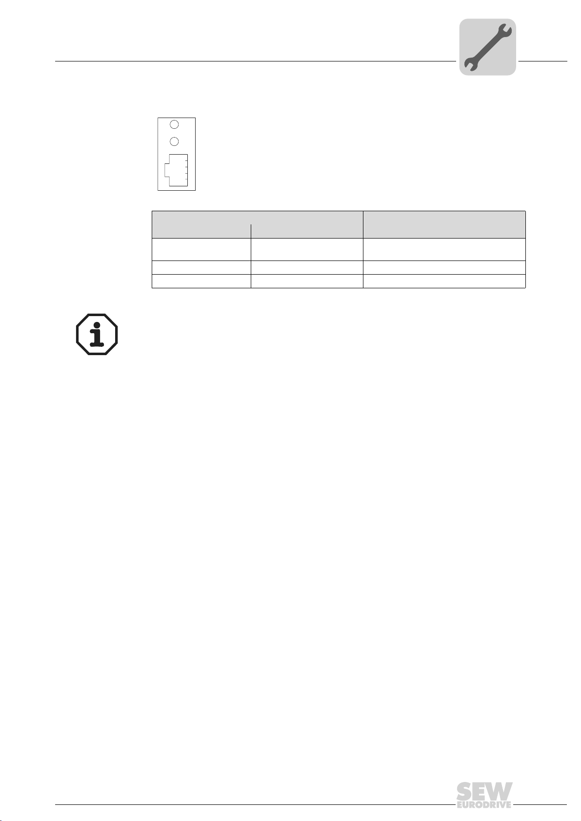
LEDs for gateway
Phone: 800.894.0412 - Fax: 888.723.4773 - Web: www.clrwtr.com - Email: info@clrwtr.com
communication
status
Assembly and Installation Notes
Operating mode displays: option DFP21B
H1
H2
X24
58129axx
LED H1 Sys-fault (red) Only for gateway function
Status Status Description
Red System error Gateway is not configured or one of the
drives is inactive.
Off SBus ok Gateway is configured correctly
Flashing Bus scan Bus is being checked by the gateway
4
LED H2 (green) is currently reserved.
X-terminal X24 is the RS-485 interface for diagnostics via PC and MOVITOOLS
MotionStudio.
®
Manual – DFP21B PROFIBUSDP-V1 Fieldbus Interface
25
Page 26
I
Phone: 800.894.0412 - Fax: 888.723.4773 - Web: www.clrwtr.com - Email: info@clrwtr.com
5
Project Planning and Startup
00
Validity of the GSD files for DFP21B
5 Project Planning and Startup
This section provides you with information on project planning for the DP master and
startup of the drive inverter for fieldbus operation.
Current versions of the GSD files for the DFP21B option are available on the SEW
homepage under the heading "Software". Both GSD files can be used at the same time
in one STEP7 project. Once
have two directories for the operating modes PROFI-BUS DP and PROFIBUS DP-V1.
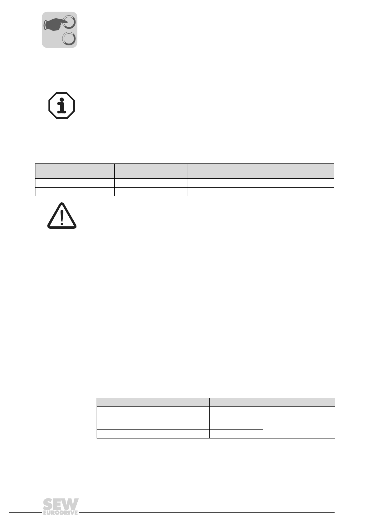
5.1 Validity of the GSD files for DFP21B
you have downloaded and unpacked the software, you will
PROFIBUS option
DFP21B074 firmware option 1:
824 399 9.10 and higher ok ok No
1820 536 4.10 and higher ok ok ok
Entries in the GSD file must not be changed or expanded. SEW assumes no liability for
inverter malfunctions caused by a modified GSD file.
SEW_6003.GSD for DP SEWA6003.GSD for DP-V1 SEW_6009.GSD for DP-V1
5.2 DP master project planning the with MOVIDRIVE® GSD file
A GSD file is provided for project planning for the DP master. This file must be copied
into a special folder of your project planning software.
Refer to the manuals of the appropriate project planning software for details on the procedure.
5.2.1 GSD file for PROFIBUSDP
Gateway operation
Use the GSD file SEW_6003.GSD from the "DP" directory if you want to use PROFI-
BUS DP communication to control the drive inverter. This GSD file corresponds to the
GSD revision1 and must be copied to a special directory of your project planning software. Refer to the manuals of the appropriate project planning software for details on
the procedure.
The unit master data files standardized by the PROFIBUS user group can be read by all
PROFIBUS DP masters.
Project planning tool DP master File name
26
All DP project planning tools to EN 50170 (V2) For DP master
standard
Siemens S7 hardware configuration For all S7 DP masters
Siemens S5 COM PROFIBUS For IM 308C etc.
Manual – DFP21B PROFIBUSDP-V1 Fieldbus Interface
SEW_6003.GSD
Page 27
DP master project planning the with MOVIDRIVE® GSD file
Phone: 800.894.0412 - Fax: 888.723.4773 - Web: www.clrwtr.com - Email: info@clrwtr.com
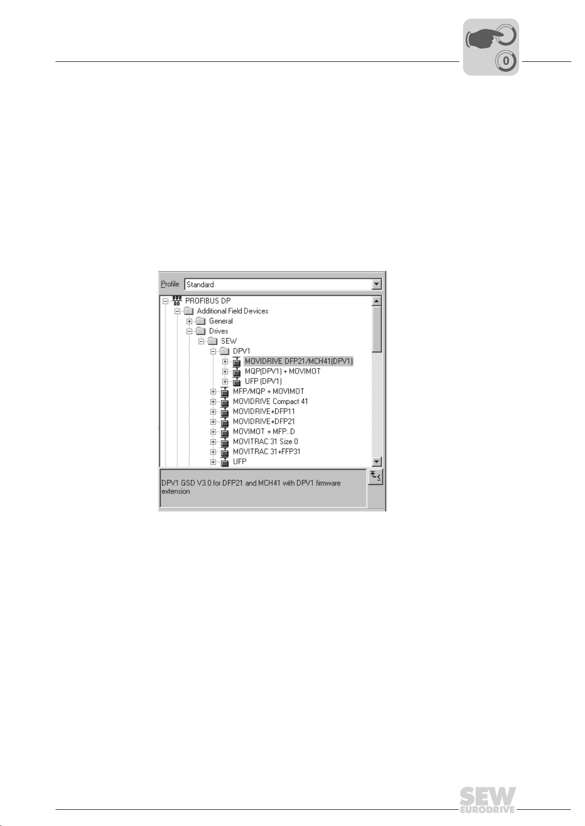
5.2.2 GSD file for PROFIBUS DP-V1
Use the GSD file SEWA6003.GSD from the "DP-V1" directory if you want to use the
parameter setting options of DP-V1 in addition to the standard PROFIBUS DP
communication to control the drive inverter.
This GSD file corresponds to GSD revision 3. If you use older, non-DP-V1-capable
PROFIBUS options, a connection is not established between the DP-V1 master and
DFP21B. In this case, the BUS FAULT LED of DFP21B remains switched on after the
DP-V1 master has started. The DP V1 master will indicate that the connection cannot
be established.
So that the GSD files are easy to identify, they are assigned the name for PROFIBUSDP-V1 and displayed in a special subdirectory in the project planning software for the
DP-V1 master (see following screenshot).
Project Planning and Startup
I
5
00
Manual – DFP21B PROFIBUSDP-V1 Fieldbus Interface
53545AXX
27
Page 28

I
Phone: 800.894.0412 - Fax: 888.723.4773 - Web: www.clrwtr.com - Email: info@clrwtr.com
5
Project Planning and Startup
DP master project planning the with MOVIDRIVE® GSD file
00
5.2.3 Project planning procedure
Proceed as follows for project planning for MOVIDRIVE
1. Read the
2. Install (copy) the GSD file according to the requirements of your project planning soft-
3. Add the interface module under the name
4. Select the process data configuration required for your application (see section 5.2.4
5. Enter the I/O or peripheral addresses for the configured data widths.
After project planning, you can start PROFIBUS DP. The red BUS FAULT LED indicates
the status of the project planning (OFF = project planning OK).
®
with PROFIBUS DP interface:
README_GSDA6003.PDF
further current information on project planning.
ware. Once the file has been installed correctly, the device appears next to the slave
stations with the designation
structure and assign the station address.
on page 29).
MOVIDRIVE®+DFP21.
file, which you receive with the GSD file for
MOVIDRIVE®+DFP21
to the PROFIBUS
28
Manual – DFP21B PROFIBUSDP-V1 Fieldbus Interface
Page 29

Project Planning and Startup
Phone: 800.894.0412 - Fax: 888.723.4773 - Web: www.clrwtr.com - Email: info@clrwtr.com
DP master project planning the with MOVIDRIVE® GSD file
5.2.4 DP configuration for MOVIDRIVE® MDX61B (SEWA6003.GSD)
The drive inverter must be given a specific DP configuration by the DP master to define
the type and number of input and output data used for transmission. You can
• Control the drive using process data
• Read and write all drive parameters using the parameter channel
• Use a data exchange medium of your choice between IPOS
®
MOVIDRIVE
exchanging data between the DP master and the inverter. The following table provides
additional information about all possible DP configurations for the MOVIDRIVE
The "Process data configuration" column lists the names of the configurations. This text
is also displayed as selection list within the project planning software for the DP master.
The "DP configurations" column shows which configuration data is sent to the inverter
when the PROFIBUS DP connection is being established.
drive inverters make it possible to have different DP configurations for
plus
and the controller
I
00
®
range.
5
Process data
configuration
1 PD MOVIDRIVE
2 PD MOVIDRIVE
3 PD MOVIDRIVE
6 PD MOVIDRIVE
10 PD MOVIDRIVE® control via 10 process data words
Param + 1 PD MOVIDRIVE® control via 1 process data word
Param + 2 PD MOVIDRIVE® control via 2 process data words
Param + 3 PD MOVIDRIVE® control via 3 process data words
Param + 6 PD MOVIDRIVE® control via 6 process data words
Param + 10 PD MOVIDRIVE® control via 10 process data words
Meaning / notes DP configuration
®
control via 1 process data word F0
®
control via 2 process data words F1
®
control via 3 process data words F2
®
(PD4-PD6 can only be used with IPOSplus
control via 6 process data words
(PD4-PD10 can only be used with IPOSplus
Parameter setting via 8 byte parameter channel
Parameter setting via 8 byte parameter channel
Parameter setting via 8 byte parameter channel
Parameter setting via 8 byte parameter channel
(PD4-PD10 can only be used with IPOSplus
Parameter setting via 8 byte parameter channel
(PD4-PD10 can only be used with IPOSplus
®
)
®
)
®
)
®
)
0 1
hex
hex
hex
0
hex
0
hex
F3
hex
F3
hex
F3
hex
F3
hex
F3
hex
-
-
-
F5
F9
F0
F1
F2
F5
F9
hex
hex
hex
hex
hex
hex
hex
Manual – DFP21B PROFIBUSDP-V1 Fieldbus Interface
29
Page 30

5
Phone: 800.894.0412 - Fax: 888.723.4773 - Web: www.clrwtr.com - Email: info@clrwtr.com
I
Project Planning and Startup
DP master project planning the with MOVIDRIVE® GSD file
00
Universal DP
configuration
If you select the "Universal Module" DP configuration (S7 HWConfig), you can structure
the DP configuration individually, although you must comply with the following
conditions.
Module 0 (DP identifier 0) defines the parameter channel of the inverter.
To ensure the parameter settings are made correctly, you must always transfer the
parameter channel consistently for the entire length.
Length Function
0 Parameter channel deactivated
8 I/O bytes or 4 I/O words Parameter channel is used
Module 1 (DP identifier 1) defines the process data channel of the inverter.
In addition to the process data configuration predefined in the GSD file, you can also
specify the process data configuration with 4, 5, 7, 8 and 9 process data words. Ensure
that the number of input and output words is always the same. If the lengths are differ-
ent, data cannot be exchanged. In this case, the BUS FAULT LED flashes and the
parameter
Length Function
2 I/O bytes or 1 I/O word 1 process data word
4 I/O bytes or 2 I/O words 2 process data words
6 I/O bytes or 3 I/O words 3 process data words
8 I/O bytes or 4 I/O words 4 process data words
10 I/O bytes or 5 I/O words 5 process data words
12 I/O bytes or 6 I/O words 6 process data words
14 I/O bytes or 7 I/O words 7 process data words
16 I/O bytes or 8 I/O words 8 process data words
18 I/O bytes or 9 I/O words 9 process data words
20 I/O bytes or 10 I/O words 10 process data words
P090 PD Configuration
indicates the configuration error with 0PD.
30
Manual – DFP21B PROFIBUSDP-V1 Fieldbus Interface
Page 31

Project Planning and Startup
Phone: 800.894.0412 - Fax: 888.723.4773 - Web: www.clrwtr.com - Email: info@clrwtr.com
DP master project planning the with MOVIDRIVE® GSD file
The following figure shows the structure of the configuration data defined in EN 50170
(V2). This configuration data is transmitted to the drive inverter during the initial start of
the DP master.
7 / MSB 6 5 4 3 2 1 0 / LSB
Data length
0000 = 1 byte/word
1111 = 16 by tes /wor ds
Input / output
00 = Special identifier formats
01 = Input
10 = Output
11 = Input / output
Format
0 = Byte structure
1 = Word structure
Integrity over
0 = Byte or word
1 = Entire length
I
5
00
Data integrity
Note:
®
MOVIDRIVE
does not support the "Special identifier formats" coding.
Only use the "Integrity over entire length" setting for data transmission.
Consistent data is data that has to be transmitted between the programmable controller
and the drive inverter as one block at all times and must never be transmitted separately.
Data integrity is especially important for the transmission of positioning values or
complete positioning tasks. Inconsistent transmission may contain data from different
program cycles of the automation device. This would lead to undefined values being
transmitted to the drive inverter.
For PROFIBUS DP, data communication between the programmable controller and
drive engineering devices is usually carried out with the setting "Data integrity over
entire length".
Manual – DFP21B PROFIBUSDP-V1 Fieldbus Interface
31
Page 32

I
Phone: 800.894.0412 - Fax: 888.723.4773 - Web: www.clrwtr.com - Email: info@clrwtr.com
5
Project Planning and Startup
DP master project planning the with MOVIDRIVE® GSD file
00
5.2.5 MOVIDRIVE® MDX61B external diagnostics
®
For MOVIDRIVE
automatic generation of external diagnostic alarms via PROFIBUS DP during the project
planning in the DP master. If this function has been activated, the inverter sends an
external diagnostic signal to the DP master every time a malfunction occurs. You then
have to program corresponding algorithms in the program of the DP master system to
evaluate the diagnostic information. These algorithms can be quite complex.
Recommendation
It is not always necessary to activate the external diagnostic function because
MOVIDRIVE
PROFIBUS DP cycle.
The structure of the unit-specific diagnostics was redefined for PROFIBUS DP-V1. The
mechanism described here can only be used with PROFIBUS DP (without DP-V1
expansions). We recommend that you do not use this mechanism for new applications.
MDX61B drive inverters with option DFP21B, it is possible to activate
®
transmits the current drive status via status word 1 during every
Procedure
Note for SIMATIC S7 master systems:
Diagnostic alarms may also be triggered by the PROFIBUS DP system in the DP master
even if external diagnostic generation is deactivated. As a result, the corresponding
operating blocks (such as OB84 for S7-400 and OB82 for S7-300) should always be
created in the controller.
Additional application-specific parameters can be defined in every DP master during
project planning for a DP slave. These parameters are transferred to the slave when the
PROFIBUS DP starts up. Nine application-specific parameter data items are provided
for MOVIDRIVE
Byte: Permitted
value
0 00 hex Reserved for DP-V1
1 00 hex Reserved for DP-V1
2 00 hex Reserved for DP-V1
3 06 hex Structured user parameter block with a length of 6 bytes
4 81 hex Structure type: User (proprietary)
5 00 hex Slot number: 0 = complete unit
6 00 hex Reserved
7 01 hex SEW user parameter version: 1
8 00 hex
01 hex
®
with the following functions:
Function
DFP21 generates a diagnostic alarm when a malfunction occurs.
DFP21 does not generate a diagnostic alarm when a malfunction occurs
(factory setting).
Values not listed here are not permitted as they can cause malfunctions in the DFP21B.
32
Manual – DFP21B PROFIBUSDP-V1 Fieldbus Interface
Page 33

Project Planning and Startup
Phone: 800.894.0412 - Fax: 888.723.4773 - Web: www.clrwtr.com - Email: info@clrwtr.com
DP master project planning the with MOVIDRIVE® GSD file
I
5
00
Project planning
example
The project planning programs of the DP master systems either offer the option of
activating the external diagnostics in plain text format, such as with STEP7 (Figure 5),
or of stating the information directly in hex code.
Figure 5: Activating external diagnostics with STEP7
Parameter data (hex) Function
00, 00, 00, 06, 81, 00, 00, 01, 00 Diagnostic alarms are generated even in case of an error
(enabled = on)
00, 00, 00, 06, 81, 00, 00, 01, 01 Diagnostic alarms are not generated if there is an error
(disabled = off, factory setting)
50256AXX
Manual – DFP21B PROFIBUSDP-V1 Fieldbus Interface
33
Page 34

I
Phone: 800.894.0412 - Fax: 888.723.4773 - Web: www.clrwtr.com - Email: info@clrwtr.com
5
Project Planning and Startup
DP master project planning with MOVITRAC® or gateway GSD file
00
5.3 DP master project planning with MOVITRAC® or gateway GSD file
This section provides information on project planning for the PROFIBUS DP master with
MOVITRAC
5.3.1 GSD files for operation in MOVITRAC
®
B and DFP21B gateway / UOH11B.
®
B and UOH11B gateway housing
11328AEN
Use the GSD file SEW_6009.GSD from the "DPV1" directory if you want to use the
DFP21B as a gateway from PROFIBUS DP-V1 on the SBus to control the drive inverter.
This GSD file corresponds to GSD revision 5.
Refer to the manuals of the appropriate project planning software for details on the
procedure.
The unit master data files standardized by the PROFIBUS user group can be read by all
PROFIBUS DP masters.
Project planning tool DP master File name
All DP project planning tools to
EN50170 (V2)
Siemens S7 hardware configuration for all S7 DP masters
for DP master standard SEW_6009.GSD
34
Manual – DFP21B PROFIBUSDP-V1 Fieldbus Interface
Page 35

DP master project planning with MOVITRAC® or gateway GSD file
Phone: 800.894.0412 - Fax: 888.723.4773 - Web: www.clrwtr.com - Email: info@clrwtr.com
5.3.2 PROFIBUSDP master startup
Supporting files for DFP21B gateway are available in the Internet at SEW web site.
.
• Observe the notes in the README.TXT file on the GSD disk.
• Install the
the DP master. After successful installation, the "DFP21B gateway" device appears
in the list of slave stations.
• Insert the interface module into the PROFIBUS structure under the name "DFP21BGateway" and assign the PROFIBUS address.
• Select the process data configuration required for your application (see section 5.3.3
on page 36).
• Enter the I/O or peripheral addresses for the projected data widths.
• Save the configuration.
• Add data exchange with the fieldbus interface to your application program. For S7,
use the system functions for consistent data exchange for this purpose (SFC14 and
SFC15).
• The BUS FAULT LED at the fieldbus interface should extinguish after you have
saved the project, loaded it in the DP master and started the DP master. If this is not
the case, check the connections and terminating resistors of the PROFIBUS and the
project planning, especially the PROFIBUS address.
GSD file
Project Planning and Startup
I
00
according to the requirements of the project planning software for
5
Manual – DFP21B PROFIBUSDP-V1 Fieldbus Interface
35
Page 36

EURODRIVE
EURODRIVE
EURODRIVE
EURODRIVE
EURODRIVE
EURODRIVE
EURODRIVE
EURODRIVE
I
Phone: 800.894.0412 - Fax: 888.723.4773 - Web: www.clrwtr.com - Email: info@clrwtr.com
5
Project Planning and Startup
DP master project planning with MOVITRAC® or gateway GSD file
00
5.3.3 Configuration of the PROFIBUSDP interface
General
The inverter must be given a specific DP configuration by the DP master to define type
and number of input and output data used for the transmission. You can control the
drives via process data and read and write all parameters of the fieldbus interface via
the parameter channel.
The figure shows a schematic view of the data exchange between automation device
(DP-V1 master), fieldbus interface (DP-V1 slave) and an inverter with process data
channel and parameter channel.
C1-Master
C2-Master C2-Master
Acyclic DP-V1
C2-Services
Unit = 8
Acyclic DP-V1
C2-Services
Acyclic DP-V1
C1-Services
Cyclic OUT Data
Param PD
Param PD
Cyclic IN Data
Unit = 1 Unit = 3
Unit = 0
DFP 21B
RUN
BUS
FAULT
01
0
2
1
2
2
2
3
2
4
2
5
2
6
2
nc
ADDRESS
X30
PROFIBUS DP-V1
Unit = 0
Unit = 5
= SBus-Address:12345678
Unit
B
®
EURODRIVEEURODRIVE
MOVITRAC
EURODRIVEEURODRIVE
EURODRIVEEURODRIVE
EURODRIVEEURODRIVE
EURODRIVEEURODRIVE
EURODRIVEEURODRIVE
EURODRIVEEURODRIVE
Figure 6: Data exchange with parameter data (Param) and process data (PD)
EURODRIVEEURODRIVE
59093AXX
36
Manual – DFP21B PROFIBUSDP-V1 Fieldbus Interface
Page 37

Project Planning and Startup
Phone: 800.894.0412 - Fax: 888.723.4773 - Web: www.clrwtr.com - Email: info@clrwtr.com
DP master project planning with MOVITRAC® or gateway GSD file
I
5
00
Configuration of
the process data
ONE module for all
drives
The fieldbus interface allows for different DP configurations for the data exchange
between DP master and fieldbus interface. The following table provides additional
details on all standard DP configurations of the fieldbus interfaces. The "Process data
configuration" column lists the names of the configurations. This text is also displayed
as selection list within the project planning software for the DP master. The DP configurations column shows the type of configuration data sent to the fieldbus interface while
the link to PROFIBUS DP is being established. The configurations are determined by
the default process data width for SEW inverters of 3 process data words. The fieldbus
interface then distributes these process data words to the individual units. The parameter channel is used for setting the parameters of the DFP21B and is not passed on to
the connected stations. The fieldbus interface accepts between 1 to 24 process data
words with and without parameter channel.
The standard entries of the GSD file are based on the DFP21B Autosetup operating
mode and allow process data widths of 3PD to 24PD corresponding to 1 to 8 inverters
connected to the fieldbus interface.
3 PDs are always assigned to any SBus station.
The process data is transmitted in one consistent data block for all inverters connected
to the fieldbus interface. Thus, only system functions SFC14 and SFC15 need to be
called in STEP7.
One module per
drive
One consistent data block exists for each connected inverter. On the controller, this
corresponds to the existing setup of several inverters with their own fieldbus interface.
System functions SFC14 and SFC15 need to be called for each inverter in STEP7.
Drive parameters of connected MOVITRAC® B inverters can only be accessed using the
DP-V1 parameter services.
Manual – DFP21B PROFIBUSDP-V1 Fieldbus Interface
37
Page 38

5
Phone: 800.894.0412 - Fax: 888.723.4773 - Web: www.clrwtr.com - Email: info@clrwtr.com
I
Project Planning and Startup
DP master project planning with MOVITRAC® or gateway GSD file
00
Process
data configuration
ONE module for all drives
Param 8 byte parame-
AS 1 Drive
(3 PD)
AS 2 Drives
(6 PD)
AS 3 Drives
(9 PD)
AS 4 Drives
(12 PD)
AS 5 Drives
(15 PD)
AS 6 Drives
(18 PD)
AS 7 Drives
(21 PD)
AS 8 Drives
(24 PD)
ONE module per drive
Param 8 byte parame-
AS 1 Drive
(1 x 3 PD)
AS 2 Drives
(2 x 3 PD)
AS 3 Drives
(3 x 3 PD)
AS 4 Drives
(4 x 3 PD)
AS 5 Drives
(5 x 3 PD)
AS 6 Drives
(6 x 3 PD)
AS 7 Drives
(7 x 3 PD)
AS 8 Drives
(8 x 3 PD)
Description Slot 1 Slot 2 Slot 3 Slot 4 Slot 5 Slot 6 Slot 7 Slot 8 Slot 9 Slot 10
ter channel
Control via 3 PD 00hex C0hex,
Control via 6 PD 00hex C0hex,
Control via 9 PD 00hex C0hex,
Control via 12 PD00hex C0hex,
Control via 15 PD00hex C0hex,
Control via 18 PD00hex C0hex,
Control via 21 PD00hex C0hex,
Control via 24 PD00hex C0hex,
ter channel
Control via
1x3 PD
Control via
2x3 PD
Control via
3x3 PD
Control via
4x3 PD
Control via
5x3 PD
Control via
6x3 PD
Control via
7x3 PD
Control via
8x3 PD
Empty Para-
meter
chan-
00hex C0hex,
87hex,
87hex
00hex C0hex,
87hex,
87hex
00hex C0hex,
00hex C0hex,
00hex C0hex,
00hex C0hex,
00hex C0hex,
00hex C0hex,
00hex C0hex,
00hex C0hex,
Drive 1 Drive 2 Drive 3 Drive 4 Drive 5 Drive 6 Drive 7 Drive 8
nel
C2hex,
C2hex
C5hex,
C5hex
C8hex,
C8hex
CBhex,
CBhex
CEhex,
CEhex
D1hex,
D1hex
D4hex,
D4hex
D7hex,
D7hex
C2hex,
C2hex
C2hex,
C2hex
C2hex,
C2hex
C2hex,
C2hex
C2hex,
C2hex
C2hex,
C2hex
C2hex,
C2hex
C2hex,
C2hex
C0hex,
C2hex,
C2hex
C0hex,
C2hex,
C2hex
C0hex,
C2hex,
C2hex
C0hex,
C2hex,
C2hex
C0hex,
C2hex,
C2hex
C0hex,
C2hex,
C2hex
C0hex,
C2hex,
C2hex
C0hex,
C2hex,
C2hex
C0hex,
C2hex,
C2hex
C0hex,
C2hex,
C2hex
C0hex,
C2hex,
C2hex
C0hex,
C2hex,
C2hex
C0hex,
C2hex,
C2hex
C0hex,
C2hex,
C2hex
C0hex,
C2hex,
C2hex
C0hex,
C2hex,
C2hex
C0hex,
C2hex,
C2hex
C0hex,
C2hex,
C2hex
C0hex,
C2hex,
C2hex
C0hex,
C2hex,
C2hex
C0hex,
C2hex,
C2hex
C0hex,
C2hex,
C2hex
C0hex,
C2hex,
C2hex
C0hex,
C2hex,
C2hex
C0hex,
C2hex,
C2hex
C0hex,
C2hex,
C2hex
C0hex,
C2hex,
C2hex
C0hex,
C2hex,
C2hex
38
Manual – DFP21B PROFIBUSDP-V1 Fieldbus Interface
Page 39

Project Planning and Startup
Phone: 800.894.0412 - Fax: 888.723.4773 - Web: www.clrwtr.com - Email: info@clrwtr.com
DP master project planning with MOVITRAC® or gateway GSD file
I
5
00
"Universal module"
DP configuration
Operating mode
(DP-V1 mode)
Module 0 must always be pre-assigned to 0x00.
The "Universal Module" (such as in STEP7) allows you to set the parameters of the fieldbus interface deviating from the preset standard values of the GSD file. This is useful if
you want to operate several inverters with different process data words at the fieldbus
interface, for example.
You must observe the following conditions:
• Module 1 defines the parameter channel of the inverter. Entering 0 will switch off the
parameter channel; entering 0xC0 0x87 0x87 will switch on the parameter channel
with 8 bytes length.
• The following modules determine the process data width of the fieldbus interface at
the PROFIBUS. The added process data width of all following modules must be
between 1 and 24 words. For safety reasons, the modules must be listed with data
integrity. Ensure that an inverter connected to the fieldbus interface is represented
by such a consistent module entry.
• Only the special identifier format is permitted.
The DP-V1 operating mode can usually be activated during project planning for a C1
master. All DP slaves, which have the DP-V1 functions enabled in their GSD files and
which support DP-V1, will then be operated in the DP-V1 mode. Standard DP slaves will
still to run via PROFIBUS DP. This ensures mixed mode is run for DP-V1 and DPcapable modules. Depending on the specification of the master functionality, a DP-V1capable station, that was configured using the DP-V1 GSD file, can run in the "DP"
operating mode.
Manual – DFP21B PROFIBUSDP-V1 Fieldbus Interface
39
Page 40

I
Phone: 800.894.0412 - Fax: 888.723.4773 - Web: www.clrwtr.com - Email: info@clrwtr.com
5
Project Planning and Startup
DP master project planning with MOVITRAC® or gateway GSD file
00
5.3.4 Autosetup for gateway operation
The Autosetup function enables startup of the DFP21B as gateway to be performed
without a PC. Activate the function via the Autosetup DIP switch (see section 4.4 on
page 20).
Switching on the Autosetup DIP switch causes the function to be performed once. The
Autosetup DIP switch must then remain in the ON position. The function can be
performed again by switching the DIP switch off and back on again.
As a first step, the DFP21B searches for drive inverters on the SBus below its hierarchi-
cal level. This process is indicated by the H1 LED (system fault) flashing briefly. Different
SBus addresses must be set for the drive inverters (P813). We recommend assigning
the addresses beginning with address 1 in ascending order based on the arrangement
of inverters in the control cabinet. The process image on the fieldbus side is expanded
by three words for each detected drive inverter.
The H1 LED remains lit if no drive inverter was located. A total of up to eight drive invert-
ers is taken into account. The following figure shows the process image for three drive
inverters with three words each of process output data and process input data.
Following the search, the DFP21B cyclically exchanges 3 process data words with each
connected drive inverter. The process output data is fetched from the fieldbus, divided
into blocks of three and transmitted. The drive inverters read the process input data, put
them together and send them to the fieldbus master.
The cycle time of the SBus communication requires 2 ms for each station.
This means the cycle time of the process data update is 8x2 ms=16 ms for an application
with 8 inverters on the SBus.
If you change the process data assignment of the drive inverters connected to the
DFP21B, you have to activate Autosetup again because the DFP21B saves these
values only once during Autosetup. At the same time, the process data assignments of
the connected drive inverters may not be changed dynamically after Autosetup.
40
Manual – DFP21B PROFIBUSDP-V1 Fieldbus Interface
Page 41

Project Planning and Startup
Phone: 800.894.0412 - Fax: 888.723.4773 - Web: www.clrwtr.com - Email: info@clrwtr.com
DP master project planning with MOVITRAC® or gateway GSD file
I
5
00
Figure 7: Data exchange DP-V1 master DFP inverter
DFP
59442AXX
Manual – DFP21B PROFIBUSDP-V1 Fieldbus Interface
41
Page 42

I
Phone: 800.894.0412 - Fax: 888.723.4773 - Web: www.clrwtr.com - Email: info@clrwtr.com
5
Project Planning and Startup
Setting the MOVIDRIVE® MDX61B drive inverter
00
5.4 Setting the MOVIDRIVE® MDX61B drive inverter
To control the drive inverter via PROFIBUS, you must first switch the drive inverter to
control signal source (P101) and setpoint source (P100) = FIELDBUS. The FIELDBUS
setting means the drive inverter parameters are set for acceptance of setpoints via
PROFIBUS. The MOVIDRIVE
transmitted from the master programmable controller.
The parameters of the MOVIDRIVE
without any further settings once the PROFIBUS option card has been installed. For
example, all parameters can be set by the master programmable controller after being
switched on.
42
®
drive inverter then responds to the process output data
®
drive inverter can be set right away via PROFIBUS
Manual – DFP21B PROFIBUSDP-V1 Fieldbus Interface
11330AEN
Page 43

Project Planning and Startup
Phone: 800.894.0412 - Fax: 888.723.4773 - Web: www.clrwtr.com - Email: info@clrwtr.com
Setting the MOVITRAC® frequency inverter
Activation of the control signal source and setpoint source FIELDBUS is signaled to the
machine control using the "Fieldbus mode active" bit in the status word.
For safety reasons, you must also enable the drive inverter at the terminals for control
via the fieldbus system. Therefore, you must wire and program the terminals in such a
way that the inverter is enabled via the input terminals. The simplest way of enabling the
drive inverter at the terminals is, for example, to connect the DIØØ (function /CONTROLLER INHIBIT) input terminal to a +24-V signal and to program input terminals
DIØ1 ... DIØ3 to NO FUNCTION. The procedure for startup of the MOVIDRIVE
inverter with a fieldbus connection is described on the next page.
5.5 Setting the MOVITRAC® frequency inverter
I
00
®
drive
5
Manual – DFP21B PROFIBUSDP-V1 Fieldbus Interface
11329AEN
43
Page 44

5
Phone: 800.894.0412 - Fax: 888.723.4773 - Web: www.clrwtr.com - Email: info@clrwtr.com
I
Project Planning and Startup
Setting the MOVITRAC® frequency inverter
00
To control the drive inverter via PROFIBUS, you must first switch the drive inverter to
control signal source (P101)
means the drive inverter parameters are set for control and setpoint entry via gateway.
The MOVITRAC
from the master programmable controller.
It is necessary to set the SBus1 timeout interval (P815) to a value other than 0 ms for
the MOVITRAC
tered. We recommend a value in the range 50 to 200 ms.
Activation of the control signal source and setpoint source SBus is signaled to the
machine control using the "SBus mode active" bit in the status word.
For safety reasons, you must also enable the drive inverter at the terminals for control
via the fieldbus system. Therefore, you must wire and program the terminals in such a
way that the inverter is enabled via the input terminals. The simplest way of enabling the
drive inverter at the terminals is, for example, to connect the DI1 (function CW/STOP)
input terminal to a +24-V signal and to program the remaining input terminals to NO
FUNCTION.
®
drive inverter then responds to the process output data transmitted
®
frequency inverter to stop if faulty SBus communication is encoun-
and
setpoint source (P100)
= SBus. The SBus setting
Set the parameter
The SBus address 0 is used by DFP21B gateway and therefore must not be used.
P883 SBus timeout
Set
P881 SBus address
to values between 50 to 200 ms.
to values between 1 to 8 in ascending order.
44
Manual – DFP21B PROFIBUSDP-V1 Fieldbus Interface
Page 45

PROFIBUSDP Operating Characteristics
Phone: 800.894.0412 - Fax: 888.723.4773 - Web: www.clrwtr.com - Email: info@clrwtr.com
Controlling the MOVIDRIVE® MDX61B drive inverter
6 PROFIBUSDP Operating Characteristics
This section describes the basic characteristics of the drive inverter with PROFIBUS DP.
6.1 Controlling the MOVIDRIVE® MDX61B drive inverter
The drive inverter is controlled via the process data channel, which is up to 10 I/O words
in length. These process data words may be mapped in the I/O or peripheral area of the
control if a programmable control is used as DP master and can be addressed as usual.
I
6
00
PW160
PW158
PW156
PW154
PW152
PW150
PW148
[2]
PW160
PW158
PW156
PW154
PW152
PW150
PW148
Figure 8: Mapping PROFIBUS data in the PLC address range
PA 3
PA 2
PA 1
PE 3
PE 2
PE 1
[1]
[1]
PA 1
PE 1
[1] 8-byte MOVILINK® parameter channel
[2] PLC address range
PA 2
PE 2
PA 3
PE 3
PA 10
PE 10
B
®
MOVIDRIVE
58688AXX
PE1 ... PE10 Process input data
PA1 ... PO10 Process output data
• For additional information on programming and project planning, refer to the
README_GSDA6003.PDF file included in the GSD file.
• For more information about controlling via the process data channel, in particular
regarding the coding of the control and status word, refer to the Fieldbus Unit Profile
manual.
Manual – DFP21B PROFIBUSDP-V1 Fieldbus Interface
45
Page 46

I
Phone: 800.894.0412 - Fax: 888.723.4773 - Web: www.clrwtr.com - Email: info@clrwtr.com
6
PROFIBUSDP Operating Characteristics
Controlling the MOVIDRIVE® MDX61B drive inverter
00
6.1.1 Control example for SIMATIC S7 with MOVIDRIVE® MDX61B
The drive inverter is controlled using SIMATIC S7 in accordance with the selected
process data configuration either directly using load and transfer commands or by
means of special system functions,
S7 data lengths of 3 bytes or more than 4 bytes must always be transmitted using
system functions SFC14 and SFC15.
Consequently, the data in the following table applies:
Process data configuration STEP7 access via
1 PD Load / transfer commands
2 PD Load / transfer commands
3 PD System functions SFC14/15 (length: 6 bytes)
6 PD System functions SFC14/15 (length: 12 bytes)
10 PD System functions SFC14/15 (length: 20 bytes)
Param + 1 PD Parameter channel: System functions SFC14/15 (length: 8 bytes)
Param + 2 PD Parameter channel: System functions SFC14/15 (length: 8 bytes)
Param + 3 PD Parameter channel: System functions SFC14/15 (length: 8 bytes)
Param + 6 PD Parameter channel: System functions SFC14/15 (length: 8 bytes)
Param + 10 PD Parameter channel: System functions SFC14/15 (length: 8 bytes)
SFC 14 DPRD_DAT
Process data: Load / transfer commands
Process data: Load / transfer commands
Process data: System functions SFC14/15 (length: 6 bytes)
Process data: System functions SFC14/15 (length: 12 bytes)
Process data: System functions SFC14/15 (length: 20 bytes)
and
SFC15 DPWR_DAT
.
®
6.1.2 PROFIBUSDP timeout (MOVIDRIVE
MDX61B)
If the data transfer via PROFIBUS DP is faulty or interrupted, the response monitoring
®
time in MOVIDRIVE
elapses (if configured in the DP master). The BUS-FAULT LED
lights up or flashes to indicate that no new user data is being received. At the same time,
MOVIDRIVE
response
P819 Fieldbus timeout
®
performs the fault response selected with
.
displays the response monitoring time specified by the DP
master during the PROFIBUS DP startup. The timeout can only be changed via the DP
master. Although modifications made using the keypad or MOVITOOLS
they do not have any effect and are overwritten when the DP is next started up.
6.1.3 Fieldbus timeout response (MOVIDRIVE
P831 is used to set the parameters for the fault response, which is triggered by the fieldbus timeout monitoring. The setting made here must correspond to the setting in the
master system (S7: response monitoring).
®
MDX61B)
P831 Fieldbus timeout
®
are displayed,
46
Manual – DFP21B PROFIBUSDP-V1 Fieldbus Interface
Page 47

PROFIBUSDP Operating Characteristics
Phone: 800.894.0412 - Fax: 888.723.4773 - Web: www.clrwtr.com - Email: info@clrwtr.com
Control of the MOVITRAC® inverter (gateway)
6.2 Control of the MOVITRAC® inverter (gateway)
The inverter is controlled via the process data channel, which is up to 3 I/O words in
length. These process data words are reproduced in the I/O or peripheral area of the
controller, for example when a programmable logic controller is used as the DP master.
As a result, they can be addressed in the usual manner.
I
6
00
PO 3
PO 2
PO 1
PO 3
PO 2
PO 1
PO 1
PO 2
PO 3
PO 1
[1]
[2]
POW318
POW316
POW314
POW312
POW310
POW308
MOVITRAC® B 1 MOVITRAC® B 2
PI 2
PI 3
PI 1
PIW318
PIW316
PIW314
PIW312
PIW310
PIW308
PI 1
PI 3
PI 2
PI 1
PI 3
PI 2
PI 1
Figure 9: Mapping PROFIBUS data in the PLC address range
[1] Address range MOVITRAC® B, device 2
®
[2] Address range MOVITRAC
B, device 1
PO 2
PI 2
PO 3
PI 3
58612AXX
PO = process output data / PI = process input data
Additional information on programming and project planning can be found in the
README_GSD6009.PDF file included in the GSD file.
Manual – DFP21B PROFIBUSDP-V1 Fieldbus Interface
47
Page 48

I
Phone: 800.894.0412 - Fax: 888.723.4773 - Web: www.clrwtr.com - Email: info@clrwtr.com
6
PROFIBUSDP Operating Characteristics
Control of the MOVITRAC® inverter (gateway)
00
6.2.1 Control example for SIMATIC S7 with MOVITRAC® B (gateway)
The drive inverter is controlled via SIMATIC S7 depending on the selected process data
configuration, either directly via load and transfer commands or via the special system
functions SFC 14 DPRD_DAT and SFC15 DPWR_DAT.
S7 data lengths of 3 bytes or more than 4 bytes must always be transmitted using
system functions SFC14 and SFC15.
Process data configuration STEP7 access via
3 PD...24 PD System functions SFC14/15
Param + 3 PD...24 PD System functions SFC14/15
(length: 6...48 bytes)
(length 6...48 bytes for PD + 8 bytes for parameter)
STEP7 program
example
6.2.2 SBus timeout
6.2.3 Unit faults
The "README_GSD6009.PDF" file contains project planning and programming
examples for SIMATIC S7. See also section 6.4 on page 55.
If one or more drive inverters on the SBus can no longer be addressed by the DFP21,
the gateway enters error code
drive inverter. The H1 LED (system fault) lights up, and the fault is also displayed via the
diagnostics interface. It is necessary to set the
MOVITRAC
error resets itself in the gateway. In other words, the current process data is exchanged
immediately after restarting the communication.
The gateways detect a series of faults during the self test and respond by locking themselves. The exact error responses and remedies can be found in the list of errors. A
hardware defect causes error
input data for status words 1 of all drive inverters. The H1 LED (system fault) at the
DFP21B then flashes at regular intervals. The exact error code is displayed in the status
of the gateway using MOVITOOLS
®
B system error to a value other than 0 for the drive inverter to stop. The
F11 System fault
, in status word 1 of the corresponding
SBus timeout interval (P815)
F111 system fault
®
MotionStudio on the diagnostic interface.
to be displayed on the fieldbus process
of the
48
Manual – DFP21B PROFIBUSDP-V1 Fieldbus Interface
Page 49

PROFIBUSDP Operating Characteristics
Phone: 800.894.0412 - Fax: 888.723.4773 - Web: www.clrwtr.com - Email: info@clrwtr.com
Parameter settings via PROFIBUS DP
6.2.4 Fieldbus timeout of the DFP21B in gateway operation
I
6
00
You can set how the gateway should respond in case of timeout using the
timeout response
No response The drives on the subordinate SBus continue with the last setpoint value.
PA_DATA=0 The rapid stop is activated for all drives that have a process data configuration
parameter.
These drives cannot be controlled when the PROFIBUS communication is interrupted.
with control word 1 or 2 when a PROFIBUS timeout is detected. For this
purpose, the gateway sets the bits 0 to 2 of the control word to 0.
The drives are stopped with the rapid stop ramp.
6.3 Parameter settings via PROFIBUS DP
With PROFIBUS DP, the drive parameters are accessed via the 8-byte MOVILINK
parameter channel. This channel offers extra parameter services in addition to the
conventional READ and WRITE services.
The inverter parameter settings via the PROFIBUS DP parameter channel can only be
used for MOVIDRIVE
The PROFIBUS DP parameter channel does not provide data access to the parameters
of the inverter that are installed below the gateway at the SBus.
6.3.1 Structure of the 8-byte MOVILINK
®
MDX61B and the parameters of the DFP21B gateway.
®
parameter channel
P831 Fieldbus
®
PROFIBUS DP enables access to the inverter drive parameters via the "Parameter
process data object" (PPO). This PPO is transmitted cyclically and contains the process
data channel [2] and a parameter channel [1] that can be used to exchange acyclical
parameter values.
[1]
[1]
Figure 10: Communication via PROFIBUS DP
[2]
[2]
53492AXX
Manual – DFP21B PROFIBUSDP-V1 Fieldbus Interface
49
Page 50

6
Phone: 800.894.0412 - Fax: 888.723.4773 - Web: www.clrwtr.com - Email: info@clrwtr.com
I
PROFIBUSDP Operating Characteristics
Parameter settings via PROFIBUS DP
00
The following table shows the structure of the 8-byte MOVILINK® parameter channel.
Essentially, the parameter channel is made up of a management byte, an index word, a
reserved byte and four data bytes.
Byte 0 Byte 1 Byte 2 Byte 3 Byte 4 Byte 5 Byte 6 Byte 7
Manage-
ment
Subindex
Index high Index low MSB data Data Data LSB data
Parameter index 4 byte data
Management of
the 8-byte
MOVILINK
®
parameter
channel
The entire procedure for setting parameters is coordinated using management byte 0.
This byte provides important service parameters such as service identifier, data length,
version and status of the service performed. The following table shows that bits 0, 1, 2
and 3 contain the service identifier, and define which service is performed. Bit 4 and bit
5 specify the data length in bytes for the WRITE service. This should be set to 4 bytes
for all SEW drive inverters.
7 / MSB 6 5 4 3 2 1 0 / LSB
Service identifier
0000 = No service
0001 = READ parameter
0010 = WRITE parameter
0110 = READ default
0111 = READ scale
1000 = READ attribute
Data length
00 = 1 byte
01 = 2 bytes
10 = 3 bytes
11 = 4 bytes (must be set)
Handshake bit
Must be changed on every new task in cyclical transmission.
Status bit
0 = No error during service execution
1 = Error during service execution
50
Bit 6 is used as a handshake between the control and the drive inverter. It triggers the
implementation of the transferred service in the drive inverter. In PROFIBUS DP. the
parameter channel is transmitted cyclically with the process data. For this reason, the
implementation of the service in the drive inverter must be triggered by edge control
using the handshake bit 6. For this purpose, the value of this bit is altered for each new
service that is to be executed. The drive inverter uses the handshake bit to signal
whether the service has been executed or not. The service was executed if the handshake bit received in the control is identical with the transmitted handshake bit. Status
bit 7 indicates whether it was possible to execute the service properly or if errors
occurred.
Manual – DFP21B PROFIBUSDP-V1 Fieldbus Interface
Page 51

PROFIBUSDP Operating Characteristics
Phone: 800.894.0412 - Fax: 888.723.4773 - Web: www.clrwtr.com - Email: info@clrwtr.com
Parameter settings via PROFIBUS DP
I
6
00
Index addressing
Data range
Incorrect service
execution
Byte 2 (Index high) and byte 3 (Index low) determine the parameter which is to be read
or written via the fieldbus system. The parameters of a drive inverter are addressed with
a uniform index regardless of the fieldbus system that is connected. Byte 1 should be
viewed as reserved and must always be set to 0x00.
As shown in the following table, the data is contained in bytes 4 through 7 of the parameter channel. This means up to 4 bytes of data can be transmitted per service. The data
is always entered with right-justification. In other words, byte 7 contains the least significant data byte (LSB data) whereas byte 4 is the most significant data byte (MSB data).
Byte 0 Byte 1 Byte 2 Byte 3 Byte 4 Byte 5 Byte 6 Byte 7
Manage-
ment
Subindex Index high Index low MSB data Data Data LSB data
High byte 1 Low byte 1 High byte 2 Low byte 2
High word Low word
Double word
The status bit in the management byte is set to signal that a service has been executed
incorrectly. The service was executed by the drive inverter if the received handshake bit
is the same as the sent handshake bit. If the status bit now signals an error, the error
code is entered in the data range of the parameter telegram. Bytes 4 through 7 send
back the return code in a structured format. See section 6.5 on page 56.
Byte 0 Byte 1 Byte 2 Byte 3 Byte 4 Byte 5 Byte 6 Byte 7
Manage-
ment
Status bit = 1: Incorrect service execution
Subindex Index high Index low Error class Error code Add. code
high:
Add. code
low
Manual – DFP21B PROFIBUSDP-V1 Fieldbus Interface
51
Page 52

I
Phone: 800.894.0412 - Fax: 888.723.4773 - Web: www.clrwtr.com - Email: info@clrwtr.com
6
PROFIBUSDP Operating Characteristics
Parameter settings via PROFIBUS DP
00
6.3.2 Reading a parameter with PROFIBUS DP (READ)
Due to the cyclical transfer of the parameter channel, to execute a READ service via the
8-byte MOVILINK
®
parameter channel, the handshake bit may only be changed if the
complete parameter channel has been set up for the specific service. For this reason,
observe the following sequence when reading a parameter:
1. Enter the index of the parameter to be read in byte2 (index high) and byte3 (index
low).
2. Enter the service identifier for the READ service in the management byte (byte0).
3. Transfer the READ service to the inverter by changing the handshake bit.
Since this is a read service, the sent data bytes (bytes 4 through 7) and the data length
(in the management byte) are ignored and consequently do not need to be set.
The inverter now processes the READ service and sends the service confirmation back
by changing the handshake bit.
7 / MSB 6 5 4 3 2 1 0 / LSB
00/1
Status bit
0 = No error during service execution
1 = Error during service execution
1) Bit value is changed
2) Not relevant
1)
Handshake bit
Must be changed on every new task in cyclical transmission.
2)
X
Data length
Not relevant for READ service
2)
X
Service identifier
0001 = READ parameter
0001
The above table shows how a READ service is coded in the management byte. The data
length is not relevant, you only need to enter the service identifier for the READ service.
This service is now activated in the drive inverter when the handshake bit changes. For
example, it would be possible to activate the READ service with the management byte
coding 01hex or 41hex.
52
Manual – DFP21B PROFIBUSDP-V1 Fieldbus Interface
Page 53

PROFIBUSDP Operating Characteristics
Phone: 800.894.0412 - Fax: 888.723.4773 - Web: www.clrwtr.com - Email: info@clrwtr.com
Parameter settings via PROFIBUS DP
6.3.3 Writing a parameter via PROFIBUS DP (WRITE)
I
6
00
Due to the cyclical transfer of the parameter channel, to execute a WRITE service via
the 8-byte MOVILINK
®
parameter channel, the handshake bit may only be changed if
the complete parameter channel has been set up for the specific service. For this
reason, observe the following sequence when writing a parameter:
1. Enter the index of the parameter to be written in byte 2 (index high) and byte 3 (index
low).
2. Enter the data to be written in bytes 4 through 7.
3. Enter the service identifier and the data length for the WRITE service in the manage-
ment byte (byte 0).
4. Transfer the WRITE service to the inverter by changing the handshake bit.
The inverter now processes the WRITE service and sends the service confirmation back
by changing the handshake bit.
The following table shows how a WRITE service is coded in the management byte. The
data length is 4 bytes for all parameters of SEW drive inverters. This service is now
transferred to the drive inverter when the handshake bit changes. As a result, a WRITE
service on SEW drive inverters generally has the management byte coding 32hex or
72hex.
7 / MSB 6 5 4 3 2 1 0 / LSB
00/1
Status bit
0 = No error during service execution
1 = Error during service execution
1) Bit value is changed
1)
Handshake bit
Must be changed on every new task in cyclical transmission.
110010
Service identifier
0010 = WRITE Parameter
Data length
11 = 4 bytes
Manual – DFP21B PROFIBUSDP-V1 Fieldbus Interface
53
Page 54

I
Phone: 800.894.0412 - Fax: 888.723.4773 - Web: www.clrwtr.com - Email: info@clrwtr.com
6
PROFIBUSDP Operating Characteristics
Parameter settings via PROFIBUS DP
00
6.3.4 Parameter setting procedure with PROFIBUS DP
Using the WRITE service as an example, the following figure represents a process of
setting parameters between the controller and the drive inverter via PROFIBUS DP. To
simplify the procedure, the following figure only shows the management byte of the
parameter channel.
The parameter channel is only received and returned by the drive inverter while the
control is preparing the parameter channel for the WRITE service. The service is not
activated until the moment when the handshake bit is changed (in this example, when it
changes from 0 to 1). The drive inverter now interprets the parameter channel and
processes the WRITE service; however, it continues to respond to all telegrams with
handshake bit = 0. Confirmation that the service has been performed occurs when the
handshake bit in the response telegram of the drive inverter is changed. The control now
detects that the received handshake bit is once again the same as the one that was sent.
It can now prepare another parameter setting procedure.
Control PROFIBUS DP(V0) Drive inverter (slave)
Parameter channel is
prepared for the WRITE
service
Handshake bit is changed
and the service is transferred to the drive inverter -- 01110010XXX... →
Service confirmation is
received as the send and
receive handshake bits are
the same again
-- 00110010XXX... →
← 00110010XXX... --
← 00110010XXX... --
-- 01110010XXX... →
← 00110010XXX... -- WRITE service is performed,
← 01110010XXX... --
-- 01110010XXX... → Parameter channel is received, but
Parameter channel is received, but
not evaluated
handshake bit is changed
not evaluated
6.3.5 Parameter data format
When parameters are set via the fieldbus interface, the same parameter coding is used
as with the serial RS-485 interfaces or the system bus.
The data formats and ranges of values for the individual parameters can be found in the
publication "MOVIDRIVE
54
®
Parameter List".
Manual – DFP21B PROFIBUSDP-V1 Fieldbus Interface
Page 55

PROFIBUSDP Operating Characteristics
Phone: 800.894.0412 - Fax: 888.723.4773 - Web: www.clrwtr.com - Email: info@clrwtr.com
SIMATIC STEP7 program example
6.4 SIMATIC STEP7 program example
This example is a special and free service that demonstrates only the basic approach to
generating a PLC program without commitment. We are not liable for the contents of the
program example.
In this example, the project planning for MOVIDRIVE® or MOVITRAC® has the process
data configuration "3 PD" on input addresses PIW576... and output addresses
POW576...
A data block DB3 is created with about 50 data words.
When SFC14 is called, the process input data is copied to data block DB3, data words
0, 2 and 4. When SFC15 is called after the control program has been processed, the
process output data are copied from data words 20, 22 and 24 to the output address
POW 576 ...
Note the length information in bytes for the RECORD parameter. The length information
must correspond to the configured length.
Refer to the online help for STEP7 for further information about the system functions.
I
6
00
//Start of cyclical program processing in OB1
BEGIN
NETWORK
TITLE =Copy PI data from inverter to DB3, words 0/2/4
CALL SFC 14 (DPRD_DAT) //READ DP slave record
LADDR := W#16#240 //Input address 576
RET_VAL:= MW 30 //Result in flag word 30
RECORD := P#DB3.DBX 0.0 BYTE 6 //Pointer
NETWORK
TITLE =PLC program with drive application
// PLC program uses the process data in DB3 for
// controlling the drive
L DB3.DBW 0//Load PI1 (status word 1)
L DB3.DBW 2 //Load PI2 (actual speed value)
L DB3.DBW 4 //Load PI3 (no function)
L W#16#0006
T DB3.DBW 20//Write 6hex to PO1 (control word = enable)
L 1500
T DB3.DBW 22//Write 1500dec to PO2 (speed setpoint = 300 rpm)
L W#16#0000
T DB3.DBW 24//Write 0hex to PO3 (however, it has no function)
//End of cyclical program processing in OB1
NETWORK
TITLE =Copy PO data from DB3, word 20/22/24 to inverter
CALL SFC 15 (DPWR_DAT) //WRITE DP Slave Record
LADDR := W#16#240 //Output address 576 = 240hex
RECORD := P#DB3.DBX 20.0 BYTE 6 //Pointer to DB/DW
RET_VAL:= MW 32 //Result in flag word 32
Manual – DFP21B PROFIBUSDP-V1 Fieldbus Interface
55
Page 56

I
Phone: 800.894.0412 - Fax: 888.723.4773 - Web: www.clrwtr.com - Email: info@clrwtr.com
6
PROFIBUSDP Operating Characteristics
Return codes for parameter setting
00
6.5 Return codes for parameter setting
6.5.1 Elements
In the event of an incorrect parameter setting, the drive inverter sends back various
return codes to the master that set the parameters. These codes provide detailed information about what caused the error. Generally, these return codes are structured. The
system distinguishes between the following elements:
• Error class
• Error code
• Additional code
These return codes are described in detail in the Fieldbus Communications Profile
manual and are not included in this documentation. However, the following special
cases can occur in connection with PROFIBUS:
6.5.2 Error class
6.5.3 Error code
The error class element provides a more exact classification of the error type.
MOVIDRIVE
EN 50170(V2):
Class (hex) Designation Meaning
1 vfd state Status error of the virtual field device
2 application reference Error in application program
3 definition Definition error
4 resource Resource error
5 service Fault during service execution
6 access Access error
7 ov Error in the object directory
8 other Other error (see section 6.5.4 on page 57)
Except for
tions software of the fieldbus card when faulty communication is encountered. Return
codes sent from the drive inverter system are all in
can be identified more precisely using the
®
supports the following error classes defined in accordance with
Error class 8 = other error
, the error class is generated by the communica-
Error class 8 = other error
Additional code
element.
. The error
The error code element allows for a more detailed identification of the error cause within
the error class and is generated by the communications software of the fieldbus card
56
when faulty communication is encountered. For
code = 0
the
(other error code) is defined. In this case, detailed identification is made using
Additional code
.
Manual – DFP21B PROFIBUSDP-V1 Fieldbus Interface
Error class 8 = other error
, only
error
Page 57

6.5.4 Additional code
Phone: 800.894.0412 - Fax: 888.723.4773 - Web: www.clrwtr.com - Email: info@clrwtr.com
The additional code contains the return codes specific to SEW dealing with incorrect
parameter settings of the drive inverter. They are returned to the master under
class 8 = other error
code.
PROFIBUSDP Operating Characteristics
Special cases
. The following table shows all possible codings for the additional
I
6
00
Error
Add. code
high (hex)
00 00 No error
00 10 Illegal parameter index
00 11 Function/parameter not implemented
00 12 Read access only
00 13 Parameter lock is active
00 14 Factory setting is active
00 15 Value for parameter too large
00 16 Value for parameter too small
00 17 Required option card missing for this function/parameter
00 18 Error in system software
00 19 Parameter access via RS-485 process interface on X13 only
00 1A Parameter access via RS-485 diagnostic interface only
00 1B Parameter is access-protected
00 1C Control inhibit required
00 1D Invalid value for parameter
00 1E Factory setting was activated
00 1F Parameter was not saved in EEPROM
00 20 Parameter cannot be changed with enabled output stage
Add. code
low (hex)
Meaning
6.6 Special cases
6.6.1 Special return codes
Errors in the parameter settings that cannot be identified either automatically by the
application layer of the fieldbus system or by the system software of the drive inverter
are treated as special cases. The following is a list of errors that can occur depending
on the fieldbus option card used:
• Incorrect coding of a service via parameter channel
• Incorrect length specification of a service via parameter channel
• Internal communication error
Manual – DFP21B PROFIBUSDP-V1 Fieldbus Interface
57
Page 58

6
Phone: 800.894.0412 - Fax: 888.723.4773 - Web: www.clrwtr.com - Email: info@clrwtr.com
I
PROFIBUSDP Operating Characteristics
Special cases
00
Incorrect service
code in the
parameter
channel
Troubleshooting
Incorrect length
specification in
parameter
channel
Incorrect code was specified in the management byte or reserved byte during parameter
setting via the parameter channel. The following table shows the return code for this
special case.
Code (dec) Meaning
Error class: 5 Service
Error code: 5 Illegal parameter
Add. code high: 0 –
Add. code low: 0 –
Check bits 0 and 1 in the parameter channel.
A data length other than 4 data bytes was specified in a READ or WRITE service when
setting parameters via the parameter channel. The following table displays the return
codes.
Code (dec) Meaning
Error class: 6 Access
Error code: 8 Type conflict
Add. code high: 0 –
Add. code low: 0 –
Troubleshooting
Internal communication error
Troubleshooting
Check bits 4 and 5 for the data length in the management byte of the parameter channel.
Both bits must be set to 1.
The return code listed in the following table is sent back if a communication error has
occurred within the system. The parameter service transferred via the fieldbus may not
have been performed and should be repeated. If this error occurs again, switch off the
drive inverter completely and then back on again so it is re-initialized.
Code (dec) Meaning
Error class: 6 Access
Error code: 2 Hardware fault
Add. code high: 0 –
Add. code low: 0 –
Repeat the READ or WRITE service. If this error occurs again, disconnect the drive
inverter from the supply system and then reconnect it. Contact SEW Service for advice
if this error occurs continuously.
58
Manual – DFP21B PROFIBUSDP-V1 Fieldbus Interface
Page 59

7 PROFIBUSDP-V1 Functions
Phone: 800.894.0412 - Fax: 888.723.4773 - Web: www.clrwtr.com - Email: info@clrwtr.com
This section provides you with information about the PROFIBUS DP-V1 functions.
7.1 Introduction to PROFIBUS DP-V1
This section describes the functions and terms used for operating SEW drive inverters
on PROFIBUS DP-V1. Refer to the PROFIBUS user group or visit PROFIBUS website
for detailed technical information on PROFIBUS DP-V1.
The PROFIBUS DP-V1 specification introduced new acyclical
as part of the PROFIBUS DP-V1 expansions. These acyclical services are added to the
current cyclical bus operation in special telegrams to ensure compatibility with PROFI-
BUS DP (version 0) and PROFIBUS DP V1 (version 1).
The acyclical
between master and slave (drive inverter) than it would be possible to transfer in the
cyclical input and output data using the 8-byte parameter channel. The advantage of the
acyclical data exchange via DP-V1 lies in the minimum load on the cyclical bus operation since DP-V1 telegrams are only added to the bus cycle if required.
The DP-V1 parameter channel provides the user with 2 options:
• The higher-level controller can access all the device information of the SEW DP-V1
slaves. This means that cyclical process data and unit settings can be read, stored
in the controller and modified in the slave.
• It is also possible to route the service and startup tool MOVITOOLS
via the DP-V1 parameter channel instead of using a proprietary RS-485 connection.
Once you have installed the MOVITOOLS
detailed information in the folder ...\SEW\MOVITOOLS\Fieldbus.
The main features of PROFIBUS DP-V1 are explained below.
READ/WRITE
PROFIBUSDP-V1 Functions
I
Introduction to PROFIBUS DP-V1
00
READ/WRITE
services can be used to exchange larger data quantities
®
®
MotionStudio software, you can access
services
MotionStudio
7
C1-Master
Acyclic DP-V1
C1-Services
Cyclic OUT Data
Param PD
Param PD
Cyclic IN Data
SEW
Drive
C2-Master
Acyclic DP-V1
C2-Services
PROFIBUS DP-V1
Acyclic DP-V1
C2-Services
C2-Master
58617AXX
Manual – DFP21B PROFIBUSDP-V1 Fieldbus Interface
59
Page 60

I
Phone: 800.894.0412 - Fax: 888.723.4773 - Web: www.clrwtr.com - Email: info@clrwtr.com
7
PROFIBUSDP-V1 Functions
Introduction to PROFIBUS DP-V1
00
7.1.1 Class 1 master (C1 master)
The PROFIBUSDP-V1 network differentiates between master classes. The C1 master
essentially performs the cyclical data exchange with the slaves. A typical C1 master is
a control system, such as a PLC, that exchanges cyclical process data with the slave. If
the DPV1 function has been activated via the GSD file, the acyclical connection between
C1 master and slave is established automatically when the cyclical connection of the
PROFIBUS-DP-V1 is being established. Only one C1 master can be operated in a
PROFIBUSDP-V1 network.
7.1.2 Class 2 master (C2 master)
The C2 master itself does not perform cyclical data exchange with the slaves. Examples
for a typical C2 master are visualization systems or temporary installed programming
devices (notebook / PC). The C2 master uses exclusively acyclic connections for
communication with the slaves. The acyclic connections between C2 master and slave
are established by the
service has been performed successfully. An established connection allows for cyclical
data exchange with the slaves by means of
masters can be active in a DP-V1 network. The number of C2 connections, established
simultaneously for a slave, is determined by the slave. SEW drive inverters support two
parallel C2 connections.
initiate
service. The connection is established once the
READ
or
WRITE
services. Several C2
initiate
7.1.3 Data sets (DS)
The user data transported via a DP-V1 service is collected in data sets. Each data set
is represented uniquely by its length, a slot number and an index. The structure of data
set 47 is used for DP-V1 communication with the SEW drive inverter. This data set is
defined as the DP-V1 parameter channel for drives as of V3.1 in the PROFIdrive profile
drive engineering of the PROFIBUS user group. Different procedures for accessing
parameter data in the drive inverter are provided via this parameter channel.
60
Manual – DFP21B PROFIBUSDP-V1 Fieldbus Interface
Page 61

7.1.4 DP-V1 services
Phone: 800.894.0412 - Fax: 888.723.4773 - Web: www.clrwtr.com - Email: info@clrwtr.com
The DP-V1 expansions offer new services, which can be used for acyclical data
exchange between master and slave. The system distinguishes between the following
services:
PROFIBUSDP-V1 Functions
Introduction to PROFIBUS DP-V1
C1 master Connection type: MSAC1 (master / slave acyclical C1)
READ Read data set
WRITE Write data set
C2 master: Connection type: MSAC2 (master / slave acyclical C2)
INITIATE Establish C2 connection
ABORT Disconnect C2 connection
READ Read data set
WRITE Write data set
I
7
00
7.1.5 DP-V1 alarm handling
In addition to the acyclical services, the DP-V1 specification also defines extended
alarm handling. Alarm handling now distinguishes between different alarm types. As a
result, unit-specific diagnostics cannot be evaluated in DP-V1 operation using the
"DDLM_SlaveDiag" DP-V0 service. DP-V1 alarm handling has not been defined for
drive engineering as a drive inverter does not usually transfer its status information via
cyclical process data communication.
Manual – DFP21B PROFIBUSDP-V1 Fieldbus Interface
61
Page 62

r
I
Phone: 800.894.0412 - Fax: 888.723.4773 - Web: www.clrwtr.com - Email: info@clrwtr.com
7
PROFIBUSDP-V1 Functions
Features of SEW drive inverters
00
7.2 Features of SEW drive inverters
The SEW fieldbus interfaces to PROFIBUS DP-V1 have the same communication
features for the DP-V1 interface. The drives are usually controlled via a C1 master with
cyclical process data in accordance with the DP-V1 standard. This C1 master (usually
a PLC) can also use an 8-byte MOVILINK
exchange to perform the parameter services with DFP21B. The READ and WRITE
services give the C1 master access to connected stations via the DP-V1 C1 channel.
Two additional C2 channels can be connected in parallel to these parameter channels.
The first C2 master as a visualization device, for example could use these channels to
read parameter data, and a second C2 master in the form of a notebook could use them
to configure the drive using the MOVITOOLS
®
parameter channel during cyclical data
®
software.
C1-Master
DP:
DP-V1 Interface
SEW PROFIBUS
DP:
PD
Acyclic DP-V1
C1-Services
8 Byte Param
Cyclic IN/Out
Process Data
DP Parameterbuffer
Parameterbuffer
Drive System
Figure 11: Parameter channels for PROFIBUS DP-V1
C2-Master C2-Maste
PROFIBUS DP-V1
Acyclic DP-V1
C2-Services
C1-Parameterbuffer
C2-Parameterbuffer
C2-Parameterbuffer
cyclic
Acyclic DP-V1
C2-Services
53124AXX
62
Manual – DFP21B PROFIBUSDP-V1 Fieldbus Interface
Page 63

PROFIBUSDP-V1 Functions
Phone: 800.894.0412 - Fax: 888.723.4773 - Web: www.clrwtr.com - Email: info@clrwtr.com
Structure of the DP-V1 parameter channel
7.3 Structure of the DP-V1 parameter channel
Generally, the parameter setting of the drives to the PROFIdrive DP-V1 parameter
channel of profile version 3.0 is implemented via data set 47. The
used to distinguish between parameter access based on PROFIdrive profile or via SEWMOVILINK
elements. The data set structure is the same for PROFIdrive and MOVILINK
®
services. The following table shows the possible codes of the individual
Request ID
®
I
7
00
entry is
access.
DP-V1
READ/WRITE
The following MOVILINK
• 8-byte MOVILINK
inverter such as
– READ parameter
– WRITE parameter
– WRITE parameter volatile
–Etc.
PROFIdrive
Parameter Channel
DS47
®
parameter channel with all the services supported by the drive
SEW MOVILINK
®
services are supported:
®
53125AXX
Manual – DFP21B PROFIBUSDP-V1 Fieldbus Interface
63
Page 64

7
Phone: 800.894.0412 - Fax: 888.723.4773 - Web: www.clrwtr.com - Email: info@clrwtr.com
I
PROFIBUSDP-V1 Functions
Structure of the DP-V1 parameter channel
00
The following PROFIdrive services are supported:
• Reading (request parameter) individual parameters of type
• Writing (change parameter) individual parameters of type
Table 1: Elements of data set DS47
Box Data type Values
Request
reference
Request ID Unsigned8 0x01 Request parameter (PROFIdrive)
Response ID Unsigned8 Response (+):
Axis Unsigned8 0x00 ... 0xFF Number of axes 0 ... 255
No. of parameters
Attributes Unsigned8 0x10 value
No. of elements Unsigned8 0x00 for parameters that are not indexed
Parameter number
Subindex Unsigned16 0x0000 SEW: Always 0
Format Unsigned8 0x43 Double word
No. of values Unsigned8 0x00 ... 0xEA Quantity 0 ... 234
Error value Unsigned16 0x0000 ... 0x0064 PROFIdrive error codes
Unsigned8 0x00 Reserved
0x01 ... 0xFF
0x02 Change parameter (PROFIdrive)
0x40 SEW MOVILINK
0x00 reserved
0x01 Request parameter (+) (PROFIdrive)
0x02 Change parameter (+) (PROFIdrive)
0x40 SEW-MOVILINK® service (+)
Response (–):
0x81 Request parameter (–) (PROFIdrive)
0x82 Change parameter (–) (PROFIdrive)
0xC0 SEW-MOVILINK® service (–)
Unsigned8 0x01 ... 0x13 1 ... 19 DWORDs (240 DP-V1 data bytes)
For SEW MOVILINK
0x00 No service
0x10 READ parameter
0x20 WRITE parameter
0x30 WRITE parameter volatile
0x40 ... 0xF0 reserved
0x01 ... 0x75 Quantity 1 ... 117
Unsigned16 0x0000 ... 0xFFFF MOVILINK parameter index
0x44 Error
0x0080 + MOVILINK
For SEW MOVILINK
double word
®
service
®
(request ID = 0x40):
®
additional code low
®
16-bit error value
double word
64
Manual – DFP21B PROFIBUSDP-V1 Fieldbus Interface
Page 65

Structure of the DP-V1 parameter channel
Phone: 800.894.0412 - Fax: 888.723.4773 - Web: www.clrwtr.com - Email: info@clrwtr.com
7.3.1 Parameter setting procedure via data set 47
PROFIBUSDP-V1 Functions
I
7
00
Parameter access is provided by the combination of the DP-V1 services
READ
. The parameter setting service is transferred to the slave with
WRITE
WRITE.req
followed by slave-internal processing.
The master now sends a
master repeats the
READ.req
READ.req
if the
to pick up the parameter setting response. The
READ.res
from the slave is negative. As soon as the
parameter processing in the drive inverter is concluded, it answers with a positive
response
parameter setting order that was previously sent with
READ.res.
The user data now contain the parameter setting response of the
WRITE.req
(see the following
illustration). This mechanism applies to a C1 as well as a C2 master.
Master
Parameter
Request
PROFIBUS-DP-V1
WRITE.req DS47
with data (parameter request)
WRITE.res
without data
READ.req DS47
without data
READ.res(-)
without data
Slave (Drive)
Parameter
Request
Parameter
Processing
and
READ.req DS47
without data
Parameter
Response
Figure 12: Telegram sequence for parameter access via PROFIBUSDP-V1
with data (parameter response)
READ.res(+)
Parameter
Response
53126AXX
Manual – DFP21B PROFIBUSDP-V1 Fieldbus Interface
65
Page 66

I
Phone: 800.894.0412 - Fax: 888.723.4773 - Web: www.clrwtr.com - Email: info@clrwtr.com
7
PROFIBUSDP-V1 Functions
Structure of the DP-V1 parameter channel
00
7.3.2 DP-V1 master processing sequence
If the bus cycles are very short, the request for the parameter response arrives before
the inverter has concluded parameter access in the device. This means that the
response data from the inverter is not yet available. In this case, the inverter sends a
negative answer with the Error_Code _1 = 0xB5 (status conflict) to the DP-V1 level.
The DP-V1 master must then send another request with the above-mentioned
READ.req headeruntil it receives a positive response from the drive inverter.
Send Write request
with parameter data
Check Write.
response
Write.response
positive
Send DS_Read.req
with parameter data
Read.
response
status
conflict?
No
Other error
or timeout
No
Parameter transfer ok,
data available
Write.response
negative
Yes
Yes
Parameter transfer
cancelled with ERROR
53127AEN
66
Manual – DFP21B PROFIBUSDP-V1 Fieldbus Interface
Page 67

Structure of the DP-V1 parameter channel
Phone: 800.894.0412 - Fax: 888.723.4773 - Web: www.clrwtr.com - Email: info@clrwtr.com
7.3.3 Addressing connected drive inverters
The structure of the DS47 data set defines an axis element. This element is used to
reach multi-axis drives that are operated via one PROFIBUS interface. The axis element
addresses one of the devices connected via the PROFIBUS interface. This mechanism
can be used, for example, by the SEW MQP bus modules for MOVIMOT
MOVITRAC
®
07.
PROFIBUSDP-V1 Functions
I
00
®
or UFP for
7
Addressing a
MOVIDRIVE
®
inverter one the
PROFIBUS DP-V1
With the setting
Axis = 0
, the parameter of the drive inverters can be accessed directly.
Since there are no drive devices connected to the MOVIDRIVE
is returned with an error code.
C1-Master
C2-Master
Cyclic OUT Data
Param PD
Param PD
Acyclic DP-V1
C1-Services
Cyclic IN Data
Axis = 0
Acyclic DP-V1
C2-Services
Axis = 0
Axis = 0
®
, access with
C2-Master
PROFIBUS DP-V1
Acyclic DP-V1
C2-Services
Axis > 0
7.3.4 MOVILINK
Figure 13: Addressing a MOVIDRIVE® directly via PROFIBUSDP-V1 with Axis = 0
®
parameter requests
®
The MOVILINK
structure of data set 47. The Request ID 0x40 (SEW MOVILINK
exchange of MOVILINK
MOVILINK
parameter channel of the SEW drive inverter is directly mapped in the
®
®
®
services usually takes place according to the structure described below.
parameter setting request. Parameter access with
service) is used for the
The typical telegram sequence for data set 47 is used.
®
Request-ID: 0x40 SEW-MOVILINK
The actual service is defined by the data set element
service
Attribute
on the MOVILINK
parameter channel. The high nibble of this element corresponds to the service nibble in
the management byte of the DP parameter channel.
53556AXX
®
Manual – DFP21B PROFIBUSDP-V1 Fieldbus Interface
67
Page 68

7
Phone: 800.894.0412 - Fax: 888.723.4773 - Web: www.clrwtr.com - Email: info@clrwtr.com
I
PROFIBUSDP-V1 Functions
Structure of the DP-V1 parameter channel
00
Example for
reading a parameter via
MOVILINK
®
The following tables show an example of the structure of the WRITE.request and
READ.res user data for reading an individual parameter via the MOVILINK
®
parameter
channel.
Sending parameter request
The table shows the coding of the user data for the
DP-V1 header. The
WRITE.req
service is used to transfer the parameter setting request
WRITE.req
service specifying the
to the drive inverter. The firmware version is read.
Table 2: WRITE.request header for transferring the parameter request
Service: WRITE.request Description
Slot_Number 0 Random, (is not evaluated)
Index 47 Index of the data set; constant index 47
Length 10 10 byte user data for parameter request
Table 3: WRITE.req USER DATA for MOVILINK® "READ parameter"
Byte Field Value Description
0 Request reference 0x01 Individual reference number for the parameter
1 Request ID 0x40 SEW MOVILINK
2 Axis 0x00 Axis number; 0 = single axis
3 No. of parameters 0x01 1 parameter
4 Attributes 0x10 MOVILINK
5 No. of elements 0x00 0 = access to direct value, no subelement
6, 7 Parameter number 0x206C MOVILINK
8, 9 Subindex 0x0000 Subindex 0
setting request, mirrored in the parameter
response
®
service
®
service "READ parameter"
®
index 8300 = "Firmware version"
Query parameter response
The following table shows the coding of the READ.req USER DATA including the DPV1 header.
Table 4: READ.req for requesting the parameter response
Service: READ.request Description
Slot_Number 0 Random, (is not evaluated)
Index 47 Index of the data set; constant index 47
Length 240 Maximum length of response buffer in the DP-V1 master
Positive MOVILINK
®
parameter response
The table shows the READ.res USER DATA with the positive response data of the
parameter setting request. For example, the parameter value for index 8300 (firmware
version) is returned.
Table 5: DP-V1 header of the positive READ.response with parameter response
Service: READ.request Description
Slot_Number 0 Random, (is not evaluated)
Index 47 Index of the data set; constant index 47
Length 10 10 byte user data in response buffer
68
Manual – DFP21B PROFIBUSDP-V1 Fieldbus Interface
Page 69

PROFIBUSDP-V1 Functions
Phone: 800.894.0412 - Fax: 888.723.4773 - Web: www.clrwtr.com - Email: info@clrwtr.com
I
Structure of the DP-V1 parameter channel
00
Table 6: Positive response for MOVILINK® service
Byte Field Value Description
0 Response reference 0x01 Reflected reference number from the parameter
1 Response ID 0x40 Positive MOVILINK
2 Axis 0x00 Reflected axis number; 0 = single axis
3 No. of parameters 0x01 1 parameter
4 Format 0x43 Parameter format: Double word
5 No. of values 0x01 1 value
6, 7 Value Hi 0x311C Higher-order part of the parameter
8, 9 Value Lo 0x7289 Lower-order part of the parameter
setting request
®
response
Decoding:
0x 311C 7289 = 823947913 dec
>> Firmware version 823 947 9.13
7
Example for
writing a
parameter via
MOVILINK
®
As an example, the following tables show the structure of the
services for the volatile writing of the value 12345 to IPOS
index 11000). The MOVILINK
®
service
WRITE parameter volatile
plus®
WRITE
and
variable H0 (parameter
is used for this
purpose.
Send "WRITE parameter volatile" request
Table 7: DP-V1 header of the WRITE.request with parameter request
Service: WRITE.request Description
Slot_Number 0 Random, (is not evaluated)
Index 47 Index of the data set; constant index 47
Length 16 16-byte user data for order buffer
Table 8: WRITE.req user data for MOVILINK® service "WRITE parameter volatile"
Byte Field Value Description
0 Request reference 0x01 Individual reference number for the parameter
1 Request ID 0x40 SEW MOVILINK
2 Axis 0x00 Axis number; 0 = single axis
3 No. of parameters 0x01 1 parameter
4 Attributes 0x30 MOVILINK
5 No. of elements 0x00 0 = access to direct value, no subelement
6, 7 Parameter number 0x2AF8 Parameter index 11000 = "IPOS variable H0"
8, 9 Subindex 0x0000 Subindex 0
10 Format 0x43 Double word
11 No. of values 0x01 Change 1 parameter value
12, 13 Value HiWord 0x0000 Higher-order part of the parameter value
14, 15 Value LoWord 0x0BB8 Lower-order part of the parameter value
setting request, mirrored in the parameter
response
®
service
®
service "WRITE parameter volatile"
READ
After sending this WRITE.request, the WRITE.response is received. If there was no
status conflict in processing of the parameter channel, a positive WRITE.response
results. Otherwise, the status fault is located in Error_code_1.
Manual – DFP21B PROFIBUSDP-V1 Fieldbus Interface
69
Page 70

7
Phone: 800.894.0412 - Fax: 888.723.4773 - Web: www.clrwtr.com - Email: info@clrwtr.com
I
PROFIBUSDP-V1 Functions
Structure of the DP-V1 parameter channel
00
Query parameter response
The following table shows the coding of the WRITE.req USER DATA including the DPV1 header.
Table 9: READ.req for requesting the parameter response
Field Value Description
Function_Num READ.req
Slot_Number X Slot_Number not used
Index 47 Index of the data set
Length 240 Maximum length of response buffer in the DP master
Positive response to "WRITE Parameter volatile"
Table 10: DP-V1 header of the positive READ.response with parameter response
Service: READ.response Description
Slot_Number 0 Random, (is not evaluated)
Index 47 Index of the data set; constant index 47
Length 4 4-byte user data in response buffer
Negative
parameter
response
Table 11: Positive response for MOVILINK® service "WRITE parameter"
Byte Field Value Description
0 Response reference 0x01 Reflected reference number from the parameter
1 Response ID 0x40 Positive MOVILINK
2 Axis 0x00 Reflected axis number; 0 = single axis
3 No. of parameters 0x01 1 parameter
setting request
®
response
The following table shows the coding of a negative response of a MOVILINK® service.
Bit 7 is entered in the response ID if the response is negative.
Table 12: Negative response for MOVILINK® service
Service: READ.response Description
Slot_Number 0 Random, (is not evaluated)
Index 47 Index of the data set; constant index 47
Length 8 8-byte user data in response buffer
Byte Field Value Description
0 Response reference 0x01 Reflected reference number from the parameter setting request
®
1 Response ID 0xC0 Negative MOVILINK
2 Axis 0x00 Reflected axis number; 0 = single axis
3 No. of parameters 0x01 1 parameter
4 Format 0x44 Error
5 No. of values 0x01 1 error code
®
6, 7 Error value 0x0811 MOVILINK
e.g. Error class 0x08, Add. code 0x11
(see section "MOVILINK
for DP-V1" on page page 71)
return code
response
®
return code of the parameter settings
70
Manual – DFP21B PROFIBUSDP-V1 Fieldbus Interface
Page 71

PROFIBUSDP-V1 Functions
Phone: 800.894.0412 - Fax: 888.723.4773 - Web: www.clrwtr.com - Email: info@clrwtr.com
Structure of the DP-V1 parameter channel
I
7
00
MOVILINK parameter setting return
codes for DP-V1
The following table shows the return codes that are returned by the SEW DP-V1
interface if an error occurs during DP-V1 parameter access.
MOVILINK
Return codes (hex)
0x0810 Invalid index, parameter index does not exist in the unit
0x0811 Function/parameter not implemented
0x0812 Read access only
0x0813 Parameter lock active
0x0814 Factory setting is active
0x0815 Value for parameter too large
0x0816 Value for parameter too small
0x0817 Required option card not installed
0x0818 Error in system software
0x0819 Parameter access via RS-485 process interface only
0x081A Parameter access via RS-485 diagnostic interface only
0x081B Parameter is access-protected
0x081C Control inhibit is required
0x081D Invalid value for parameter
0x081E Factory setting was activated
0x081F Parameter was not saved in EEPROM
0x0820 Parameter cannot be changed with output stage enabled / reserved
0x0821 Reserved
0x0822 Reserved
0x0823 Parameter may be changed at IPOS program stop only
0x0824 Parameter may only be changed Autosetup is deactivated
0x0505 Incorrect coding of management and reserved byte
0x0602 Communication error between inverter system and fieldbus option card
0x0502 Timeout of secondary connection (such as during reset or with Sys-Fault)
Description
Manual – DFP21B PROFIBUSDP-V1 Fieldbus Interface
71
Page 72

I
Phone: 800.894.0412 - Fax: 888.723.4773 - Web: www.clrwtr.com - Email: info@clrwtr.com
7
PROFIBUSDP-V1 Functions
Structure of the DP-V1 parameter channel
00
7.3.5 PROFIdrive parameter requests
The PROFIdrive parameter channel of SEW drive inverters is directly mapped in the
structure of data set 47. Parameter access with PROFIdrive services usually takes place
according to the structure described below. The typical telegram sequence for data set
47 is used. PROFIdrive only defines the following two request IDs:
Request ID:0x01Request parameter (PROFIdrive)
Request ID:0x02Change parameter (PROFIdrive)
This means that there is restricted data access in comparison with the MOVILINK
services.
The request ID = 0x02 = Change parameter (PROFIdrive) results in remanent write
access to the selected parameter. Consequently, the internal flash/EEPROM of the
inverter is written with each write access. Use the MOVILINK
eter volatile" if parameters must be written cyclically at short intervals. With this service,
you only alter the parameter values in the RAM of the inverter.
®
service "WRITE Param-
®
Example for
reading a
parameter
according to
PROFIdrive
The following tables show an example of the structure of the WRITE.request and
READ.resuser data for reading an individual parameter via the MOVILINK
®
parameter
channel.
Sending parameter request
The table shows the coding of the user data for the WRITE.reqservice specifying the
DP-V1 header. The WRITE.req service is used to transfer the parameter setting request
to the drive inverter.
Table 13: WRITE.request header for transferring the parameter request
Service: WRITE.request Description
Slot_Number 0 Random, (is not evaluated)
Index 47 Index of the data set; constant index 47
Length 10 10-byte user data for parameter request
Table 14: WRITE.req USER DATA for PROFIdrive "Request parameter"
Byte Field Value Description
0 Request reference 0x01 Individual reference number for the parameter
1 Request ID 0x01 Request parameter (PROFIdrive)
2 Axis 0x00 Axis number; 0 = single axis
3 No. of parameters 0x01 1 parameter
4 Attributes 0x10 Access to parameter value
5 No. of elements 0x00 0 = access to direct value, no subelement
6, 7 Parameter number 0x206C MOVILINK
8, 9 Subindex 0x0000 Subindex 0
setting request, mirrored in the parameter
response
®
index 8300 = "Firmware version"
72
Manual – DFP21B PROFIBUSDP-V1 Fieldbus Interface
Page 73

PROFIBUSDP-V1 Functions
Phone: 800.894.0412 - Fax: 888.723.4773 - Web: www.clrwtr.com - Email: info@clrwtr.com
I
Structure of the DP-V1 parameter channel
00
Query parameter response
The following table shows the coding of the READ.req USER DATA including the DPV1 header.
Table 15: READ.req for requesting the parameter response
Service: READ.request Description
Slot_Number 0 Random, (is not evaluated)
Index 47 Index of the data set; constant index 47
Length 240 Maximum length of response buffer in the DP-V1 master
Positive PROFIdrive parameter response
The table shows the READ.res user data with the positive response data of the
parameter setting request. For example, the parameter value for index 8300 (firmware
version) is returned.
Table 16: DP-V1 header of the positive READ.response with parameter response
Service: READ.request Description
Slot_Number 0 Random, (is not evaluated)
Index 47 Index of the data set; constant index 47
Length 10 10-byte user data in response buffer
7
Table 17: Positive response for MOVILINK® service
Byte Field Value Description
0 Response reference 0x01 Reflected reference number from the parameter
1 Response ID 0x01 Positive response for "Request Parameter"
2 Axis 0x00 Reflected axis number; 0 = single axis
3 No. of parameters 0x01 1 parameter
4 Format 0x43 Parameter format: Double word
5 No. of values 0x01 1 value
6, 7 Value Hi 0x311C Higher-order part of the parameter
8, 9 Value Lo 0x7289 Lower-order part of the parameter
setting request
Decoding:
0x 311C 7289 = 823947913 dec
>> firmware version 823 947 9.13
Manual – DFP21B PROFIBUSDP-V1 Fieldbus Interface
73
Page 74

7
Phone: 800.894.0412 - Fax: 888.723.4773 - Web: www.clrwtr.com - Email: info@clrwtr.com
I
PROFIBUSDP-V1 Functions
Structure of the DP-V1 parameter channel
00
Example for writing a parameter
according to
PROFIdrive
The following tables show an example of the structure of the
WRITE
and
READ
services
for the remanent writing of the internal setpoint n11 (see section "Example for writing a
parameter via MOVILINK
®
on page 69). The PROFIdrive service
Change parameter
used for this purpose.
Send "WRITE parameter"request
Table 18: DP-V1 header of the WRITE.request with parameter request
Service: WRITE.request Description
Slot_Number 0 Random, (is not evaluated)
Index 47 Index of the data set; constant index 47
Length 16 16-byte user data for order buffer
Table 19: WRITE.req user data for PROFIdrive service "Change parameter"
Byte Field Value Description
0 Request reference 0x01 Individual reference number for the parameter
1 Request ID 0x02 Change parameter (PROFIdrive)
2 Axis 0x01 Axis number; 0 = single axis
3 No. of parameters 0x01 1 parameter
4 Attributes 0x10 Access to parameter value
5 No. of elements 0x00 0 = access to direct value, no subelement
6, 7 Parameter number 0x7129 Parameter index 8489 = P160 n11
8, 9 Subindex 0x0000 Subindex 0
10 Format 0x43 Double word
11 No. of values 0x01 Change 1 parameter value
12, 13 Value HiWord 0x0000 Higher-order part of the parameter value
14, 15 Value LoWord 0x0BB8 Lower-order part of the parameter value
setting request, mirrored in the parameter
response
is
After sending this WRITE.request, the WRITE.response is received. If there was no
status conflict in processing of the parameter channel, a positive WRITE.response
results. Otherwise, the status fault is located in Error_code_1.
Query parameter response
The following table shows the coding of the WRITE.req user data including the DP-V1
header.
Table 20: READ.req for requesting the parameter response
Field Value Description
Function_Num READ.req
Slot_Number X Slot_Number not used
Index 47 Index of the data set
Length 240 Maximum length of response buffer in the DP-V1 master
74
Manual – DFP21B PROFIBUSDP-V1 Fieldbus Interface
Page 75

PROFIBUSDP-V1 Functions
Phone: 800.894.0412 - Fax: 888.723.4773 - Web: www.clrwtr.com - Email: info@clrwtr.com
I
Structure of the DP-V1 parameter channel
00
Positive response to "WRITE parameter"
Table 21: DP-V1 header of the positive READ.response with parameter response
Service: READ.response Description
Slot_Number 0 Random, (is not evaluated)
Index 47 Index of the data set; constant index 47
Length 4 4-byte user data in response buffer
Table 22: Positive response for PROFIdrive service "Change parameter"
Byte Field Value Description
0 Response reference 0x01 Reflected reference number from the parameter
1 Response ID 0x02 Positive PROFIdrive response
2 Axis 0x01 Reflected axis number; 0 = single axis
3 No. of parameters 0x01 1 parameter
setting request
7
Negative
parameter
response
The following table shows the coding of a negative response of a PROFIdrive service.
Bit 7 is entered in the response ID if the response is negative.
Table 23: Negative response for PROFIdrive service
Service: READ.response Description
Slot_Number 0 Random, (is not evaluated)
Index 47 Index of the data set; constant index 47
Length 8 8-byte user data in response buffer
Byte Field Value Description
0 Response reference 0x01 Reflected reference number from the parameter setting
1 Response ID 0x810x82 Negative response for "Request parameter," negative
2 Axis 0x00 Reflected axis number; 0 = single axis
3 No. of parameters 0x01 1 parameter
4 Format 0x44 Error
5 No. of values 0x01 1 error code
6, 7 Error value 0x0811 MOVILINK
request
response for "Change Parameter"
®
e.g. Error class 0x08, Add. code 0x11
(see section "MOVILINK
71)
return code
®
return codes for DP-V1" on page
Manual – DFP21B PROFIBUSDP-V1 Fieldbus Interface
75
Page 76

7
Phone: 800.894.0412 - Fax: 888.723.4773 - Web: www.clrwtr.com - Email: info@clrwtr.com
I
PROFIBUSDP-V1 Functions
Structure of the DP-V1 parameter channel
00
PROFIdrive
return codes for
DP-V1
This table shows the coding of the error number in the PROFIdrive DP-V1 parameter
response according to PROFIdrive profile V3.1. This table applies if you use the
PROFIdrive services "Request parameter" and/or "Change parameter".
Error no. Meaning Used for
0x00 Invalid parameter number. Access to non-existent parameters
0x01 Parameter value cannot be
changed
0x02 Minimum or maximum value
exceeded
0x03 Incorrect subindex Access to non-existent subindex
0x04 No assignment Access with subindex to parameter that is not indexed
0x05 Incorrect data type An attempt was made to change a replace a value with one
0x06 Setting not permitted (can
only be reset)
0x07 Description element cannot
be changed
0x08 Reserved (PROFIdrive profile V2: PPO write query for IR not available)
0x09 Description does not exist Access to description that is not accessible (parameter value
0x0A Reserved (PROFIdrive profile V2: incorrect access group)
0x0B No operation priority An attempt was made to change a parameter without change
0x0C Reserved (PROFIdrive profile V2: incorrect password)
0x0D Reserved (PROFIdrive profile V2: text cannot be read in cyclic data
0x0E Reserved (PROFIdrive profile V2: name cannot be read in cyclic data
0x0F No text assignment avail-
able
0x10 Reserved (PROFIdrive profile V2: no PPO write)
0x11 Request cannot be exe-
cuted due to the operating
mode
0x12 Reserved (PROFIdrive profile V2: other error)
0x13 Reserved (PROFIdrive profile V2: data cannot be read in cyclic
0x14 Incorrect value An attempt was made to change a value to one that is in the
0x15 Response is too long The length of the current response exceeds the maximum
0x16 Invalid parameter address Invalid value or value that is not valid for this attribute, num-
0x17 Incorrect format Write request: Invalid format or parameter data format that is
0x18 Number of values is not
consistent
0x19 Axis does not exist Access to an axis that does not exist
up to 0x64 Reserved –
0x65..0xFF Depends on the manufac-
turer
An attempt was made to change a parameter value that
cannot be changed
An attempt was made to change a value to one that is outside
of the limit values
that does not correspond to the data type of the parameter
An attempt was made to set a value to one larger than 0
where this is not permitted
Access to description element that cannot be changed
is exists)
rights
transfer)
transfer)
Access to text assignment that is not accessible (parameter
value exists)
Access is currently not possible and the reason is not
explained
exchange)
permitted range but is not permitted due to other long-term
reasons (parameter with specified individual values)
transmittable length
ber of elements, parameter number, subindex or a combination of these factors.
not supported
Write request: Number of values of parameter data does not
correspond to the number of elements in the parameter
address
–
76
Manual – DFP21B PROFIBUSDP-V1 Fieldbus Interface
Page 77

7.4 Project planning for a C1 master
Phone: 800.894.0412 - Fax: 888.723.4773 - Web: www.clrwtr.com - Email: info@clrwtr.com
PROFIBUSDP-V1 Functions
Project planning for a C1 master
I
7
00
A special GSD file
master. This file activates the DP-V1 functions of the DFP21B. Therefore, the functions
of the GSD file and the DFP21B firmware must correspond with one another. When you
implement the DP-V1 functions, SEW-EURODRIVE provides you with two GSD files
(see section 5.2.1 on page 26, section 5.2.2 on page 27 and section 5.3.1 on page 34).
7.4.1 Operating mode (DP-V1 mode)
The DP-V1 operating mode can usually be activated during project planning for a C1
master. All DP slaves that have the DP-V1 functions enabled in their GSD files and that
support DP-V1 will then be operated in the DP-V1 mode. Standard DP slaves will still
run via PROFIBUS DP. This ensures mixed mode is run for DP-V1 and DP-capable
modules. Depending on the specification of the master functionality, a DP-V1-capable
station that was configured using the DP-V1 GSD file, can run in the "DP" operating
mode.
SEWA6003.GSD
is required for the project planning of a DP-V1 C1
Manual – DFP21B PROFIBUSDP-V1 Fieldbus Interface
77
Page 78

I
Phone: 800.894.0412 - Fax: 888.723.4773 - Web: www.clrwtr.com - Email: info@clrwtr.com
7
PROFIBUSDP-V1 Functions
Project planning for a C1 master
00
7.4.2 Example program for SIMATIC S7
The STEP7 code stored in the GSD file shows how parameters are accessed via the
STEP7 system function modules SFB 52/53. You can copy the STEP7 code and
import/compile it as a STEP7 source.
This example is a special and free service that demonstrates only the basic approach to
generating a PLC program without commitment. We are not liable for the contents of the
program example.
Example: Function module FB5 "DPV1_Movilink_FB"
FUNCTION_BLOCK FB 5
TITLE =DPV1_Movilink_FB
//NOTE!
//This example program only shows the basics procedure.
//Neither legal nor any kind of liability can be inferred from faulty program functions and the consequences
thereof.
//System requirements:
// - DP master interface module of series S7-300 or S7-400 that support DPV1 master functions.
// - DPV1 Profibus connections from SEW (identifier "SEWA600x.GSD")
//This function module performs the parameter exchange between the inverter and the PLC via the DPV1 channel. As
data exchange via the DPV1 parameter channel is an acyclic service, the function module must be called up until
the data exchange is complete (duration starting when a parameter request is triggered via fActivate until checkback from fDone).
AUTHOR : SEW
FAMILY : Movilink
VERSION : 0.1
VAR_INPUT
Drive_IO_Address : INT ; //Periphery address of the inverter
bService : BYTE ; //Movilink service byte 0x01 = READ, 0x02 = WRITE, etc.
bAxis : BYTE ; //0 for single axis, subaddress of the axis when using UFP11A
wParameterIndex : WORD ; //Movilink parameter index
wSubIndex : WORD ; //Movilink subindex
dwWRITEData : DWORD ; //WRITEData
InstanzDB_SFB52 : BLOCK_DB ; //InstanzDB of the system function SFB52. Required for DPV1_READ
InstanzDB_SFB53 : BLOCK_DB ; //InstanzDB of the system function SFB53. Required for DPV1_WRITE
END_VAR
VAR_OUTPUT
bError : BYTE ; //No error = 0, S7 error = 1, timeout = 2, Movilink error = 3;
dwData : DWORD ; //Contains data if fError=0; S7 error code if fError=1; otherwise undef.
END_VAR
VAR_IN_OUT
fActivate : BOOL ; //Triggering the function
fBusy : BOOL ; //Busy bit. TRUE until the function is finished or timeout monitoring responds
fDone : BOOL ; //Indicates that the function is finished (with or without error)
END_VAR
VAR
fStaticBusy : BOOL ; //Storage bit for busy flag
fStaticWRITEReq : BOOL ; //When MVLK WRITEReq = TRUE or MVLK READReq = FALSE
fDPV1WRITEDone : BOOL ; //Indicates whether DPV1 WRITE was performed
fAuxflag : BOOL ;
dwStaticDriveAddr : DWORD ; //I/O address of the inverter
iStaticReqLength : INT ; //Length of the telegrams to be transmitted
MVLK_Req : STRUCT //MovilinkStruktur WRITERequest
RequestReference : BYTE := B#16#1; //REQ: Request Reference
RequestId : BYTE := B#16#40; //REQ: Request ID
Axis : BYTE ; //REQ: Axis
No_of_Parameter : BYTE := B#16#1; //REQ: No of Parameters
Attribute : BYTE ; //REQ: Attribute
No_of_Elements : BYTE ; //REQ: No of Elements
ParameterNumber : WORD ; //REQ: Parameternumber
Subindex : WORD ; //REQ: Subindex
Format : BYTE := B#16#43;
Values : BYTE := B#16#1;
WRITEData : DWORD ; //REQ: WRITEData
END_STRUCT ;
TimeoutCounter : WORD ; //Timeout counter
END_VAR
78
Manual – DFP21B PROFIBUSDP-V1 Fieldbus Interface
Page 79

PROFIBUSDP-V1 Functions
Phone: 800.894.0412 - Fax: 888.723.4773 - Web: www.clrwtr.com - Email: info@clrwtr.com
I
Project planning for a C1 master
00
VAR_TEMP
MVLK_Resp : STRUCT //Movilink structure response
ResponseReference : BYTE ; //RESP: Response reference
ResponseId : BYTE ; //RESP: Response ID
Axis : BYTE ; //RESP: Axis
No_of_Parameter : BYTE ; //RESP: No of Parameters
Attachment : ARRAY [0 .. 7 ] OF //REQ: Data
BYTE ;
END_STRUCT ;
fTempError : BOOL ;
fTempBusy : BOOL ;
fTempDone : BOOL ;
fTempValid : BOOL ;
dwTempStatus : DWORD ;
END_VAR
BEGIN
NETWORK
TITLE =Insert transfer parameter in Movilink structure
U #fActivate;
FP #fAuxflag; //If neither a parameter service is triggered
O #fBusy; //...nor processed,
SPBN END; //...then the function is ended
U #fStaticBusy; //If static busy is set, WRITE service has already been performed,
SPBN NEWR; //then go to new request
U #fDPV1WRITEDone; //If WRITE service was finished without error, go to READ
SPB READ;
SPA WRIT; //Else go to WRITE
NEWR: NOP 0; //Initialization:
UN #fStaticBusy; //Output bits and values are reset
S #fStaticBusy; //Busy output and flag bit are set
S #fBusy;
R #fDone; //DoneBit will be reset
L 0;
T #bError; //Error and data output values are set to ZERO
T #dwData;
L #Drive_IO_Address; //Convert drive address from Int to DWord
T #dwStaticDriveAddr;
//Bring data into Movilink structure (only the variable values of the structure are supplied with the input parameters here)
L #bAxis;
T #MVLK_Req.Axis;
L #bService; //Service byte is multiplied by 10 hex
SLW 4;
T #MVLK_Req.Attribute;
L #bService;
SPL ERUI; //Go to MVLK service error
SPA ERUI; // 0x00 No Service
SPA ZEHN; // 0x01 READ Parameter
SPA SEXZ; // 0x02 WRITE Parameter
SPA SEXZ; // 0x03 WRITE Parameter volatile
SPA ZEHN; // 0x04 READ Min
SPA ZEHN; // 0x05 READ Max
SPA ZEHN; // 0x06 READ Default
SPA ZEHN; // 0x07 READ Scale
SPA ZEHN; // 0x08 READ Attribute
SPA ZEHN; // 0x09 READ EEPROM
ERUI: NOP 0; // Illegal MVLK service error
L 3; //Movilink error
T #bError;
L DW#16#501; //MLER_ILLEGAL_SERVICE
SET ;
S #fDone; //Busy and done bits are reset
R #fBusy;
R #fStaticBusy;
R #fDPV1WRITEDone;
BEA ; //End function
SEXZ: NOP 0;
SET ;
S #fStaticWRITEReq; //Indicates whether the request was a MVLK WRITE request for data evaluation
L 16;
SPA LEN; //Go to defined length
ZEHN: NOP 0;
SET ;
R #fStaticWRITEReq; //Indicates whether the request was a MVLK READ request for data evaluation
L 10;
LEN: NOP 0;
T #iStaticReqLength;
L #wParameterIndex;
T #MVLK_Req.ParameterNumber;
L #wSubIndex;
T #MVLK_Req.Subindex;
L #dwWRITEData; //Data is written to the structure, no matter whether write or read access
T #MVLK_Req.WRITEData;
7
Manual – DFP21B PROFIBUSDP-V1 Fieldbus Interface
79
Page 80

7
Phone: 800.894.0412 - Fax: 888.723.4773 - Web: www.clrwtr.com - Email: info@clrwtr.com
I
PROFIBUSDP-V1 Functions
Project planning for a C1 master
00
NETWORK
TITLE =WRITEDienst
//To transfer the parameter requirement to the inverter, an SFB53 call
//(DPV1WRITE service) must be executed.
WRIT: NOP 0;
CALL SFB 53 , #InstanzDB_SFB53 (
REQ := TRUE,
ID := #dwStaticDriveAddr,
INDEX := 47,//Data set 47
LEN := #iStaticReqLength,
DONE := #fTempDone,
BUSY := #fTempBusy,
ERROR := #fTempError,
STATUS := #dwTempStatus,
RECORD := #MVLK_Req);
//Evaluation of return values
U #fTempBusy; //The FB is exited and the busy bit set if the function is not finished.
SPB ENDB;
U #fTempError; //If no error has occurred, go to read preparation.
SPBN RD_V;
SET ; //An error has occurred. Set error bit and reset busy bits
R #fBusy;
R #fStaticBusy;
R #fDPV1WRITEDone;
S #fDone;
L 1; //Issue error code 1 (S7 error)
T #bError;
L #dwTempStatus; //Return the S7 error code
T #dwData;
BEA ;
RD_V: NOP 0; //DPV1 read service preparation
SET ;
S #fDPV1WRITEDone;
NETWORK
TITLE =READDienst
//To fetch the parameter response from the inverter, a SFB52 call
//(DPV1READ service) must be executed.
READ: NOP 0;
CALL SFB 52 , #InstanzDB_SFB52 (
REQ := TRUE,
ID := #dwStaticDriveAddr,
INDEX := 47,//Data set 47
MLEN := 12,
VALID := #fTempValid,
BUSY := #fTempBusy,
ERROR := #fTempError,
STATUS := #dwTempStatus,
LEN := #iStaticReqLength,
RECORD := #MVLK_Resp);
//Evaluation of return values
U #fTempBusy; //The FB is exited and the busy bit set if the function is not finished.
SPB ENDB;
U #fTempError; //If no error has occurred, go to data evaluation.
SPBN DATA;
L #TimeoutCounter; //Timeout counter is increased
L 1;
+I ;
T #TimeoutCounter;
L #TimeoutCounter; //A timeout error is triggered when the timeout counter has reached 300
L 300;
>=I ;
SPB TOUT;
//If error xx80B5xx hex (state conflict) is reported, then another parameter order already exists and the read
operation must be repeated
L #dwTempStatus;
UD DW#16#FFFF00;
L DW#16#80B500;
==D ;
SPBN ERR;
NOP 0;
SPA ENDB;
ERR: SET ; //An error has occurred. Set error bit and reset busy bits
R #fBusy;
R #fStaticBusy;
R #fDPV1WRITEDone;
S #fDone;
L 1; //Issue error code 1 (S7 error)
T #bError;
L #dwTempStatus; //Return the S7 error code
T #dwData;
L 0;
T #TimeoutCounter; //Reset timeout counter
BEA ;
80
Manual – DFP21B PROFIBUSDP-V1 Fieldbus Interface
Page 81

PROFIBUSDP-V1 Functions
Phone: 800.894.0412 - Fax: 888.723.4773 - Web: www.clrwtr.com - Email: info@clrwtr.com
Project planning for a C1 master
DATA: NOP 0; //Data evaluation (first selection; positive or negative response)
L #MVLK_Resp.ResponseId;
L B#16#40; //positive MoviLink response?
==I ;
SPB POSR; //go to positive response
L #MVLK_Resp.ResponseId;
L B#16#C0; //negative MoviLink response?
==I ;
SPB NEGR; //go to negative response
SET ; //illegal Movilink response
S #fDone;
R #fBusy;
R #fStaticBusy;
R #fDPV1WRITEDone;
L 3; //Movilink error
T #bError;
L DW#16#502; //MLER_NO_RESPONSE
T #dwData;
L 0;
T #TimeoutCounter; //Reset timeout counter
BEA ; //End function
TOUT: NOP 0; //Timeout
L 2; //Movilink error
T #bError;
L 0;
T #dwData;
T #TimeoutCounter; //Reset timeout counter
SET ; //The function is finished:
S #fDone; //=> set Done, reset ..Busy
R #fActivate;
R #fBusy;
R #fStaticBusy;
R #fDPV1WRITEDone;
BEA ;
NETWORK
TITLE =Auswertung der Parameterdaten
POSR: NOP 0;
U #fStaticWRITEReq;
SPB WRR; //go to WRITERequestResponse
// //READRequest was performed
L #MVLK_Resp.Attachment[2]; //Received data is written into output parameter.
SLD 24;
L #MVLK_Resp.Attachment[3];
SLD 16;
+D ;
L #MVLK_Resp.Attachment[4];
SLD 8;
+D ;
L #MVLK_Resp.Attachment[5];
+D ;
T #dwData;
L 0; //kein Fehler
T #bError;
SET ; //The function is finished:
S #fDone; //=> set Done, reset fActivate, ...
R #fActivate;
R #fBusy;
R #fStaticBusy;
R #fDPV1WRITEDone;
L 0;
T #TimeoutCounter; //Reset timeout counter
BEA ;
WRR: NOP 0;
// //WRITERequest was performed
L 0; //Output parameter is filled with ZEROS
T #dwData;
L 0; //No error
T #bError;
SET ; //Clear error bits
S #fDone;
R #fActivate;
R #fBusy;
R #fStaticBusy;
R #fDPV1WRITEDone;
L 0;
T #TimeoutCounter; //Reset timeout counter
BEA ;
I
7
00
Manual – DFP21B PROFIBUSDP-V1 Fieldbus Interface
81
Page 82

I
Phone: 800.894.0412 - Fax: 888.723.4773 - Web: www.clrwtr.com - Email: info@clrwtr.com
7
PROFIBUSDP-V1 Functions
Project planning for a C1 master
00
NEGR: NOP 0;
L 3; //Movilink error
T #bError;
L #MVLK_Resp.Attachment[2]; //Write error code to output parameter
SLW 8;
L #MVLK_Resp.Attachment[3];
+I ;
T #dwData;
SET ; //The function is finished:
S #fDone; //=> set Done, reset ..Busy
R #fActivate;
R #fBusy;
R #fStaticBusy;
R #fDPV1WRITEDone;
L 0;
T #TimeoutCounter; //Reset timeout counter
BEA ;
ENDB: SET ; //Busy end
S #fBusy;
END: NOP 0;
END_FUNCTION_BLOCK
Example for calling FB5 "DPV1_Movilink_FB"
Insert these lines into your cyclical S7 program to call the function module.
FUNCTION FC 1 : VOID
TITLE =Operation of the _DPV1 parameter channel
//This example program only shows the basics procedure.
//Neither legal nor any kind of liability can be inferred from faulty program functions and the consequences
thereof.
VERSION : 0.1
BEGIN
NETWORK
TITLE =Writing an MC07 parameter
//In this example, the internal setpoint n11 (P160) is written volatile with the value 123 rpm. The parameter
service can be triggered by a positive edge at M100.0 (variable table "MC07").
//The parameter service addresses the MC07 with SBUS address 2.
//
//PROFIBUS addr. 9
//Per. addr. 512
// I
// UFP11A MC07_1 MC07_2
// I________________I_______________I
// SBUS addr.0 SBUS addr.1 SBUS addr. 2
//
//
//Note on the hardware configuration:
//The peripheral addresses ("PEW address" and "PAW address") of the UFP11A must have the same numerical value so
that the input "Drive_IO_Address" can be clearly defined.
//
//
L L#123000; //Convert the parameter value from DINT..
T MD 110; //... to DWORD
//Conversion factor/value range of the parameter value: see parameter list in the "MC07 Communication" manual
CALL FB 5 , DB 5 (
Drive_IO_Address := 512,
bService := B#16#3,//0x01 = read, 0x02 = write, 0x03 = write volatile
bAxis := B#16#2,//MC07 with SBUS addr. 2
wParameterIndex := W#16#2129,//MOVILINK parameter index 8489d = P160, internal setpoint n11
wSubIndex := W#16#0,//MOVILINK subindex = 0
dwWRITEData := MD 110,//Parameter value that is being written
InstanzDB_SFB52 := DB 201,//Instance-DB for SFB52 is required for DPV1_READ
InstanzDB_SFB53 := DB 202,//Instance-DB for SFB53 is required for DPV1_WRITE
bError := MB 118,//No error = 0; S7 error = 1, timeout = 2, MOVILINK error = 3;
dwData := MD 114,//bError = 0 => parameter value that was read; bError = 1 => S7
error code
fActivate := M 100.0,//Activation bit: Triggering a parameter request
fBusy := M 100.1,//The parameter request is being processed or a timeout has
occurred
fDone := M 100.2);//The parameter request is finished
END_FUNCTION
82
Manual – DFP21B PROFIBUSDP-V1 Fieldbus Interface
Page 83

Project planning for a C1 master
Phone: 800.894.0412 - Fax: 888.723.4773 - Web: www.clrwtr.com - Email: info@clrwtr.com
7.4.3 DP-V1 technical data for MOVIDRIVE® DFP21
GSD file for DP-V1: SEWA6003.GSD
Module name for project planning: MOVIDRIVE
Number of parallel C2 connections: 2
Supported data set: Index 47
Supported slot number: Recommended: 0
Manufacturer code: 10A hex (SEW-EURODRIVE)
Profile ID: 0
C2 response timeout 1s
Max. length C1 channel: 240 bytes
Max. length C2 channel: 240 bytes
PROFIBUSDP-V1 Functions
®
DFP21B/MCH (DP-V1)
I
7
00
7.4.4 Technical data DP-V1 for the gateway operation and MOVITRAC
GSD file for DP-V1: SEW6009.GSD
Module name for project planning: DFP21B gateway
Number of parallel C2 connections: 2
Supported data set: Index 47
Supported slot number: Recommended: 0
Manufacturer code: 10A hex (SEW-EURODRIVE)
Profile ID: 0
C2 response timeout 1 s
Max. length C1 channel: 240 bytes
Max. length C2 channel: 240 bytes
®
Manual – DFP21B PROFIBUSDP-V1 Fieldbus Interface
83
Page 84

I
Phone: 800.894.0412 - Fax: 888.723.4773 - Web: www.clrwtr.com - Email: info@clrwtr.com
7
PROFIBUSDP-V1 Functions
Project planning for a C1 master
00
7.4.5 Error codes of the DP-V1 services
This table shows possible error codes of DP-V1 services that may occur in the event of
an error in the communication on DP-V1 telegram level. This table is relevant if you want
to write your own parameter assignment block based on the DP-V1 services because
the error codes are reported directly back on the telegram level.
Bit:
7 6 5 4 3 3 2 0
Error_Class
Error_Class (from DPV1-Specification)
0x0 ... 0x9 hex =
reserved
0xA = application 0x0 = read error
0xB = access 0x0 = invalid index 0xB0 = No data block Index 47 (DB47);
0xC = resource 0x0 = read constraint conflict
0xD...0xF = user specific
Error_Code (from DP-V1Specification)
0x1 = write error
0x2 = module failure
0x3 to 0x7 = reserved
0x8 = version conflict
0x9 = feature not supported
0xA to 0xF = user specific
0x1 = write length error
0x2 = invalid slot
0x3 = type conflict
0x4 = invalid area
0x5 = state conflict 0xB5 = Access to DB 47 temporarily not
0x6 = access denied
0x7 = invalid range 0xB7 = WRITE DB 47 with error in the DB 47
0x8 = invalid parameter
0x9 = invalid type
0xA to 0xF = user specific
0x1 = write constraint conflict
0x2 = resource busy
0x3 = resource unavailable
0x4..0x7 = reserved
0x8..0xF = user specific
Error_Code
DP-V1 Parameter channel
parameter requests are not supported
possible due to intenal processing status
header
84
Manual – DFP21B PROFIBUSDP-V1 Fieldbus Interface
Page 85

Operation of MOVITOOLS® MotionStudio via PROFIBUS
Phone: 800.894.0412 - Fax: 888.723.4773 - Web: www.clrwtr.com - Email: info@clrwtr.com
Introduction
8 Operation of MOVITOOLS® MotionStudio via PROFIBUS
This section describes the operation of the MOVITOOLS® MotionStudio via PROFIBUS.
8.1 Introduction
PROFIBUS DP-V1 provides the user with acyclical parameter services in addition to
cyclical process data. These acyclic parameter services can be used by the control
system (class 1 or C1 master) as well as by other diagnostics and visualization devices
(class 2 or C2 master).
C1-Master
I
8
00
C2-Master
C2-Services
Acyclic DP-V1
C1-Services
Cyclic OUT Data
Param PD
Param PD
Cyclic IN Data
C2-Master
Acyclic DP-V1
C2-Services
PROFIBUS DP-V1
Acyclic DP-V1
SEW
Drive
58617AXX
"MOVITOOLS
There are two configuration variants:
Access via Softnet-DP driver The Softnet-DP driver from Siemens is installed on the diagnostics PC.
Access via STEP7 A PG/PC PROFIBUS connection is configured and transferred to the
®
via PROFIBUS DP-V1" makes use of the features of the C2 master.
A connection to the drive can then be established by means of acyclical
C2 services and MOVITOOLS
This configuration variant is independent of the C1 master. For example,
a connection can even be established if the C1 master has failed.
See section 8.5 for a description of how to configure the SIMATIC Net.
programmable controller in NetPro / SIMATIC STEP7. If STEP7 version
5.3 SP3 is installed on your PC, the Softnet driver need not be installed
on the diagnostics PC.
®
MotionStudio can be used online.
Manual – DFP21B PROFIBUSDP-V1 Fieldbus Interface
85
Page 86

I
Phone: 800.894.0412 - Fax: 888.723.4773 - Web: www.clrwtr.com - Email: info@clrwtr.com
8
Operation of MOVITOOLS® MotionStudio via PROFIBUS
Required hardware
00
8.2 Required hardware
8.3 Required software
Siemens PROFIBUS master card (CP5512, CP5611)
6GK1561-1AA00 SIMATIC NET CP5611 PCI card PCI card for PCs
6GK1551-2AA00 SIMATIC NET CP5512
PCMCIA card
• STEP7 version 5.3, SP3
or
• Siemens Softnet DP PC driver for PROFIBUSDP, version 6.0 or higher
PCMCIA card for notebook
32-bit cardbus
8.4 Installation
6GK1704-5DW61-3AA0 SIMATIC NET PB Softnet DP 6.1 Driver package for WinNT 4.0,
®
•MOVITOOLS
• Install the PROFIBUS master card into the diagnostics PC and install the driver
according to the manufacturers specifications.
• Install the MOVITOOLS
MotionStudio, version 5.20 or higher
®
MotionStudio.
Win2k
86
Manual – DFP21B PROFIBUSDP-V1 Fieldbus Interface
Page 87

Operation of MOVITOOLS® MotionStudio via PROFIBUS
Phone: 800.894.0412 - Fax: 888.723.4773 - Web: www.clrwtr.com - Email: info@clrwtr.com
8.5 Configuring SIMATIC NET
• Start the program "Set PG-PC interface" from the start menu [SIMATIC]/[SIMATIC
NET]/[Settings] or from the Windows system control.
• Set the access path of the application as displayed in the following image:
Configuring SIMATIC NET
I
8
00
Figure 14: Setting the PG/PC interface
If SIMATIC STEP7 is installed on the computer and is started there from the program
"Set PG-PC interface", the field for the access path is deactivated. Start the program via
the start menu as described above.
11307AEN
Manual – DFP21B PROFIBUSDP-V1 Fieldbus Interface
87
Page 88

8
Phone: 800.894.0412 - Fax: 888.723.4773 - Web: www.clrwtr.com - Email: info@clrwtr.com
I
Operation of MOVITOOLS® MotionStudio via PROFIBUS
Configuring SIMATIC NET
00
• Press the "Properties" button. The following dialog box opens:
Figure 15: Setting properties
• Set the required parameters and ensure that the PC (in most cases) is added as a
class 2 master in an existing PROFIBUS network.
– If a PLC is active as a class 1 master, the check box [PG/PC is the only master
on Bus] must be deactivated.
– Assign the PC a free address that is not yet reserved by other masters or
slaves.
– The baud rate must match the baud rate if the class 1 master.
• Select "DP" as the profile or set the bus timing parameters according to the existing
PROFIBUS network.
11308AEN
88
Manual – DFP21B PROFIBUSDP-V1 Fieldbus Interface
Page 89

Operation of MOVITOOLS® MotionStudio via PROFIBUS
Phone: 800.894.0412 - Fax: 888.723.4773 - Web: www.clrwtr.com - Email: info@clrwtr.com
Configuring SIMATIC NET
• Close the configuration dialog and open the following dialog box using the
"Diagnostics" button to check it.
I
8
00
Figure 16: SIMATIC NET diagnostics
Everything has been correctly configured up to now when the "OK" status is displayed
after pressing the "Test" button and all devices on the PROFIBUS are displayed using
the "Read" button. You can now operate MOVITOOLS
DP-V1.
11309AEN
®
MotionStudio via PROFIBUS-
Manual – DFP21B PROFIBUSDP-V1 Fieldbus Interface
89
Page 90

I
Phone: 800.894.0412 - Fax: 888.723.4773 - Web: www.clrwtr.com - Email: info@clrwtr.com
8
Operation of MOVITOOLS® MotionStudio via PROFIBUS
Configuration of SEW communication server
00
8.6 Configuration of SEW communication server
To operate MOVITOOLS® MotionStudio via PROFIBUS DP-V1, you require the
CP5512-PC option card and the associated Softnet-DP driver package from Siemens.
The PC is connected to an existing PROFIBUS network as a class 2 master and can
communicate with inverters via acyclic parameter services using the DP-V1 protocol. To
be able to operate the MOVITOOLS
configure the SEW communication server.
8.6.1 Establishing communication
®
MotionStudio via PROFIBUS, you must first
8.6.2 Procedure
MOVITOOLS
from SEW-EURODRIVE GmbH&CoKG via several, different communication paths at
the same time.
When you start MOVITOOLS
server, and an additional icon will appear in the Windows status bar.
3 steps are involved in configuring the communication:
1. Start the SEW communication server by double-clicking the icon in the Windows task
bar.
®
MotionStudio allows you to communicate with the electronics products
®
MotionStudio, you will also start the SEW communication
11327AXX
90
Manual – DFP21B PROFIBUSDP-V1 Fieldbus Interface
Page 91

Operation of MOVITOOLS® MotionStudio via PROFIBUS
Phone: 800.894.0412 - Fax: 888.723.4773 - Web: www.clrwtr.com - Email: info@clrwtr.com
Configuration of SEW communication server
2. Activate the communication media tool bar by pressing the depicted icon.
I
8
00
11325AXX
3. Configure the requested interface using drag and drop. Use the mouse to drag the
required connection from the [Available Plugs] field to one of the four communication
channels and enter the information in the dialog windows.
Manual – DFP21B PROFIBUSDP-V1 Fieldbus Interface
58656AXX
91
Page 92

8
Phone: 800.894.0412 - Fax: 888.723.4773 - Web: www.clrwtr.com - Email: info@clrwtr.com
I
Operation of MOVITOOLS® MotionStudio via PROFIBUS
Configuration of SEW communication server
00
When configuring the PROFIBUS connection, you can set up the PROFIBUS server
when starting MOVITOOLS
The following message appears when attempting to establish communication with
PROFIBUS:
®
MotionStudio by activating the following dialog:
11311AEN
11312AXX
After the PROFIBUS connection is successfully started, the PB server icon
appears in the Windows task bar.
11310AXX
92
Manual – DFP21B PROFIBUSDP-V1 Fieldbus Interface
Page 93

Operation of MOVITOOLS® MotionStudio via PROFIBUS
Phone: 800.894.0412 - Fax: 888.723.4773 - Web: www.clrwtr.com - Email: info@clrwtr.com
Automatic search for connected units (unit scan)
8.7 Automatic search for connected units (unit scan)
After pressing the <F5> function key or the "Online-Scan" button , all configured
communication channels will be searched automatically and the addressable units
displayed in the unit tree.
I
8
00
8.8 Activating online operation
• Perform the unit scan (see section 8.7).
• Use the mouse to highlight the unit you want to operate. Switch MOVITOOLS
MotionStudio to online mode by pressing the "Online mode" button.
11315ADE
®
• Now highlight the unit you want to operate and activate the plug-in menu using the
right mouse button.
Manual – DFP21B PROFIBUSDP-V1 Fieldbus Interface
11316ADE
93
Page 94

I
Phone: 800.894.0412 - Fax: 888.723.4773 - Web: www.clrwtr.com - Email: info@clrwtr.com
8
Operation of MOVITOOLS® MotionStudio via PROFIBUS
Known problems when operating MOVITOOLS® MotionStudio
00
8.9 Known problems when operating MOVITOOLS® MotionStudio
Check the following points if problems occur during configuration:
• Is the PC connected to the PROFIBUS without violating the bus structure?
• Are the terminating resistors at the bus connectors correctly switched?
• Is the bus address of the PC still available for use?
Operation via SIMATIC NET:
• Is the check box "PG/PC is the only master on the bus" enabled/disabled?
• Is the baud rate set correctly?
94
Manual – DFP21B PROFIBUSDP-V1 Fieldbus Interface
Page 95

9 Error Diagnostics
Phone: 800.894.0412 - Fax: 888.723.4773 - Web: www.clrwtr.com - Email: info@clrwtr.com
9.1 Diagnostic procedures
The diagnostic procedures described in the following section demonstrate the fault
analysis methods for the most frequent problems:
• Inverter does not work on PROFIBUS-DP
• Inverter cannot be controlled using the DP master
For more information dealing specifically with the inverter parameter settings for various
fieldbus applications, refer to the
manual. In addition, read the current information on the GSD disk.
Error Diagnostics
Diagnostic procedures
Fieldbus Unit Profile and MOVIDRIVE® Parameter List
9
Manual – DFP21B PROFIBUSDP-V1 Fieldbus Interface
95
Page 96

9
Error Diagnostics
Diagnostic procedures
Diagnostic problem 1: Inverter does not work on PROFIBUS.
Initial status:
• Inverter is connected to PROFIBUS
• Inverter configured in PROFIBUS master and bus communication is
active
↓
Is the bus connector plugged in? no → [A]
Yes
↓
Response of the LED BUS FAULT?
FLASHES
↓
Inverter detects baud rate (P092 Baud rate fieldbus). However it was not
configured, or was configured incorrectly, in the PROFIBUS master.
↓
Check the configured bus address and the one set using the DIP switches
(P093 Fieldbus address)
↓
Are the bus addresses the same? no → [D]
Yes
↓
You may have configured an incorrect unit type or defined the configuration
incorrectly
↓
Delete the project planning for the inverter from the DP network.
↓
Perform project planning for the inverter again, choosing the unit designation
"MOVIDRIVE
To simplify the project planning process, use a predefined configuration (for
example, "Param + 3PD"). Do not change any of the preset configuration
data.
Assign the address range for your control system.
Load the configuration in the DP master and start the bus communication
again.
®
+DFP21".
↓
↓
[A] Check the bus cabling.
OFF →
ON →
[B]
[C]
96
[B] Inverter is currently exchanging data cyclically with the PROFIBUS master.
P090 PD configuration displays the configuration that the inverter is
controlled with via PROFIBUS.
↓
Bus communication is functioning properly (for problems with controlling or
setpoint selection via PROFIBUSDP, continue with Diagnostic problem2).
[C] Inverter does not detect the baud rate (P092 Baud rate fieldbus).
↓
Check the bus cabling.
[D] Modify the bus addresses.
Manual – DFP21B PROFIBUSDP-V1 Fieldbus Interface
Page 97

Error Diagnostics
Phone: 800.894.0412 - Fax: 888.723.4773 - Web: www.clrwtr.com - Email: info@clrwtr.com
Diagnostic procedures
Diagnostic problem 2:
Inverter cannot be controlled using the DP master.
Initial status:
• Bus communication with inverter OK (LED BUS FAULT off)
• Inverter running with 24 V (no supply voltage)
↓
The problem is either caused by incorrect parameter settings in the inverter or a
faulty control program in the PROFIBUS master.
↓
Use P094 ... P097 (setpoint description PO1 ... PO3) to check whether the setpoints sent by the controller are received correctly.
To do so, send a setpoint other than 0 as a test in each output word.
↓
Setpoints received? yes → [A]
No
↓
Check that the correct settings have been made for the following drive parameters:
• P100 SETPOINT SOURCE FIELDBUS
(for MOVITRAC B = SBus1 / Fixed setpoint)
• P101 CONTROL SIGNAL SOURCEFIELDBUS
(for MOVITRAC B = SBus1)
• P876 ENABLE PO DATA YES
↓
Settings OK? no → [B]
Yes
↓
The problem may be caused by your control program in the DP master.
↓
Check that the address used in the program is the same as the address for project
planning.
Note that the inverter requires consistent data and access must take place within
the control program, if necessary, via special system functions (for example,
SIMATIC S7, SFC 14 / 15).
9
[A] Setpoints are not transferred.
Check whether the drive inverter has been enabled at the terminals.
[B] Correct the settings.
Manual – DFP21B PROFIBUSDP-V1 Fieldbus Interface
97
Page 98

9
Phone: 800.894.0412 - Fax: 888.723.4773 - Web: www.clrwtr.com - Email: info@clrwtr.com
9.2 List of errors
Error Diagnostics
List of errors
Error
code
17 Stack overflow SBus communication
18 Stack underflow SBus communication
19 NMI SBus communication
20 Undefined
21 Protection fault SBus communication
22 Illegal word
23 Illegal instruc-
25 Eeprom SBus communication
28 Fieldbus timeout Default: PO data = 0
37 Watchdog error SBus communication
45 Initialization
111 System error
Designation Response Cause Measure
stopped
stopped
stopped
opcode
operand access
tion access
error
device timeout
SBus communication
stopped
stopped
SBus communication
stopped
SBus communication
stopped
stopped
Error response
adjustable via P831
stopped
SBus communication
stopped
None Check the red system error LED (H1) of
Malfunction of inverter electronics,
possibly due to EMC influence
Error while accessing EEPROM Activate factory settings, perform
No communication between master
and slave within the projected response
monitoring.
Error during execution of system software
Error after self-test during reset Perform a reset. Consult SEW service
the DFP. If this LED is on, one or several stations on the SBus could not be
addressed within the timeout interval. If
the red system error LED (H1) flashes,
the DFP itself is in an error state. In this
case, error F111 was reported to the
control only via fieldbus.
Check grounding and shielding and
improve, if necessary. Consult SEW
service if the error occurs again.
reset and set parameters for DFP
again. Contact SEW service if the
error occurs again.
• Check communications routine of
the master
• Extend the fieldbus timeout interval (response monitoring) in the
master configuration or deactivate
monitoring
Contact SEW Service.
if the error occurs again.
Check voltage supply and SBus
cabling, check SBus terminating
resistors. Check the project planning
if the DFP was configured with the
PC. Switch DFP off and on again. If
the error is still present, query the
error via diagnostic interface and perform the action described in this table.
98
Manual – DFP21B PROFIBUSDP-V1 Fieldbus Interface
Page 99

Option DFP21B for MOVIDRIVE® MDX61B
Phone: 800.894.0412 - Fax: 888.723.4773 - Web: www.clrwtr.com - Email: info@clrwtr.com
10 Technical Data
10.1 Option DFP21B for MOVIDRIVE® MDX61B
Option DFP21B (MOVIDRIVE® MDX61B)
Part number 824 240 2
Power consumption P = 3 W
PROFIBUS protocol
options
Automatic baud rate
detection
Connection technology • Via 9-pin sub D plug
Bus termination Not integrated, implement using suitable PROFIBUS plug with terminat-
Station address 1 to 125, adjustable via DIP switches
Name of the GSD file • SEW_6003.GSD (PROFIBUS DP)
DP ident. number 6003
Application-specific
parameter-setting data
(Set-Prm application
data)
DP configurations for
DDLM_Chk_Cfg
Diagnostics data • Max. 8 bytes
Tools for startup • PC program MOVITOOLS
PROFIBUSDP and DP-V1 according to IEC 61158
9.6 kBaud to 12 MBaud
• Pin assignment according to IEC 61158
ing resistors that can be switched on.
• SEWA6003.GSD (PROFIBUS DP-V1)
= 24579
hex
• Length: 9 bytes
• Hex parameter settings 00,00,00,06,81,00,00,01 = DP diagnostics alarm
= OFF
• Hex parameter settings 00,00,00,06,81,00,00,01,00 = DP diagnostics
alarm = ON
• F0hex = 1 process data word (1 I/O word)
• F1hex = 2 process data words (2 I/O words)
• F2hex = 3 process data words (3 I/O words)
• 0hex, F5hex = 6 process data words (6 I/O words)
• 0hex, F9hex = 10 process data words (10 I/O words)
• F3hex, F0hex = parameter channel + 1 process data word (5 I/O words)
• F3hex, F1hex = parameter channel + 2 process data words (6 I/O words)
• F3hex, F2hex = parameter channel + 3 process data words (7 I/O words)
• F3hex, F5hex = parameter channel + 6 process data words (10 I/O
words)
• F3hex, F9hex = parameter channel +10 process data words (14 I/O
words)
• Standard diagnostics: 6 bytes
• DBG11B keypad
dec
Technical Data
®
MotionStudio
kVA
i
P
f
Hz
n
10
Manual – DFP21B PROFIBUSDP-V1 Fieldbus Interface
99
Page 100

10
Phone: 800.894.0412 - Fax: 888.723.4773 - Web: www.clrwtr.com - Email: info@clrwtr.com
kVA
i
n
f
Technical Data
DFP21B option for MOVITRAC® B and UOH11B gateway housing
Hz
P
10.2 DFP21B option for MOVITRAC® B and UOH11B gateway housing
4.5
5.5
224
30
28
257.5
234.5
22.5
100
185
59796AXX
Figure 17: Device dimensions of the UOH11B gateway housing
DFP21B option (MOVITRAC® B gateway)
Part number 824 240 2
External voltage supply V = DC 24 V (–15 %, +20 %)
PROFIBUS protocol options PROFIBUS DP and DP-V1 according to IEC 61158
Automatic baud rate detection 9.6 kBaud to 12 MBaud
Connection technology • Via 9-pin sub D plug
Bus termination Not integrated, must be implemented using suitable PROFIBUS connector with switchable
Station address 1 to 125, adjustable via DIP switches
Name of the GSD file SEW_6009.GSD (PROFIBUSDP-V1)
DP ident. number 6009
Application-specific parameter
setting data
(Set-Prm application data)
DP configurations for
DDLM_Chk_Cfg
Diagnostics data • Standard diagnostics: 6 bytes
Tools for startup • PC program MOVITOOLS
= DC 200 mA
I
max
= 3.4 W
P
max
• Pin assignment according to IEC 61158
terminating resistors.
= 24585
hex
• Length: 3bytes
• Hex parameter setting 00,00,00
See section "Configuration of process data" on page 37.
dec
®
MotionStudio
100
Manual – DFP21B PROFIBUSDP-V1 Fieldbus Interface
 Loading...