

Page 1

Drive Technology \ Drive Automation \ System Integration \ Services
Fieldbus Interface DFE33B
EtherNet/IP and Modbus/TCP
Edition 10/2008
16725611 / EN
Manual
Page 2

SEW-EURODRIVE – Driving the world
Phone: 800.894.0412 - Fax: 888.723.4773 - Web: www.clrwtr.com - Email: info@clrwtr.com
Page 3

Contents
1 General Information............................................................................................... 6
1.1 Using the manual........................................................................................... 6
1.2 Structure of the safety notes.......................................................................... 6
1.3 Rights to claim under warranty....................................................................... 7
1.4 Exclusion of liability........................................................................................ 7
1.5 Copyright........................................................................................................ 7
2 Safety Notes ................................ ... ... ....................................... ... ........................... 8
2.1 Other applicable documentation .................................................................... 8
2.2 General safety notes for bus systems............................................................ 8
2.3 Safety functions ............................... ... ... .... ... ... ... ....................................... ... . 8
2.4 Hoist applications......... ....................................... ... ....................................... . 8
2.5 Product names and trademarks.......... ... .... ... ... ... ... .... .................................... 8
2.6 Waste disposal............................................................................................... 8
3 Introduction ............................................................................................................ 9
3.1 Content of the manual.. .... ... ... ... .... ... ... ....................................... ... ... .............. 9
3.2 Additional documentation. ... ... ... .... ... ... ... ....................................... ... ... ........... 9
3.3 Properties....................................................................................................... 9
3.3.1 Fieldbus operation with MOVIDRIVE
3.3.2 Access to all information .............................................................. ... .. 10
3.3.3 Monitoring functions .......................................................................... 10
3.3.4 Diagnostics ....................................................................................... 10
3.3.5 Fieldbus monitor ............................................................................... 10
®
B and MOVITRAC® B ............ 9
4 Assembly and Installation Instructions ............................................................. 11
®
4.1 Installing the DFE33B option card in MOVIDRIVE
MDX61B..................... 11
4.1.1 Before you begin ............................................................................... 12
4.1.2 Basic procedure for installing/removing an option card
(MDX61B, sizes 1 – 6) ............. ... .... ... ... ... ....................................... .. 13
4.2 Installing the DFE33B option card in MOVITRAC
4.2.1 Connecting the system bus between a MOVITRAC
the DFE33B option ........................................................................... 14
4.2.2 Connecting the system bus between several MOVITRAC
®
B.................................. 14
®
B unit and
®
B units . 15
4.3 Installing the DFE33B gateway / UOH11B................................................... 17
4.4 Connection and terminal description of the DFE33B option ............... .... ... .. 18
4.5 Status LED of the DFE33B option ............................................................... 19
4.5.1 Gateway LED .................................................................................... 20
4.6 Pin assignment ............................................................................................ 21
4.7 The integrated Ethernet switch .................................................................... 22
4.8 Shielding and routing bus cables................................................................. 22
4.9 Setting the DIP switches.................................................. ....... ... ... ... ... .... ... .. 23
4.10 TCP/IP addressing and subnetworks........................................................... 24
4.11 Setting the IP address parameters............................................................... 26
4.12 Procedure for replacing the unit.... ... ... ... .... ... ... ... ....... ... ... ... .... ... ... ... ... .... ... .. 28
4.12.1 Replacing MOVIDRIVE
4.12.2 Replacing MOVITRAC
®
B ..... ... .... ... ...................................... .... ..... 28
®
B / gateway ............................................... 29
5 Project Planning and Startup (EtherNet/IP) ....................................................... 30
5.1 Validity of the EDS file for DFE33B.............................................................. 30
5.2 Configuring the master (EtherNet/IP scanner)............................................. 31
5.2.1 Configuring the DFE33B as option in MOVIDRIVE
5.2.2 Configuring the DFE33B as option in MOVITRAC
®
MDX61B ......... 32
®
B or in
the UOH11B gateway housing ......................................................... 34
5.2.3 Auto Setup for gateway operation .................................................... 36
®
5.3 Setting the MOVIDRIVE
MDX61B inverter................................................ 37
Manual – Fieldbus Interface DFE33B EtherNet/IP and Modbus/TCP
3
Page 4

Contents
5.4 Setting the MOVITRAC® B frequency inverter............................................. 38
5.5 Project planning examples in RSLogix5000..................................... ... .... ... .. 39
5.5.1 MOVIDRIVE
5.5.2 MOVITRAC
5.5.3 A cce ss to the un it pa ra met er s of MO VIDRIVE
5.5.4 MOVITRAC
6 Ethernet Industrial Protocol (EtherNet/IP)......................................................... 54
6.1 Introduction .................................................................................................. 54
6.2 Process data exchange ............................................................................... 54
6.3 CIP object directory...................................................................................... 55
6.4 Return codes for parameter setting via explicit messages........................... 68
7 Project Planning and Startup (Modbus/TCP)..................................................... 72
7.1 Unit description file for Modbus/TCP............................................................ 72
7.2 Configuring the master (Modbus scanner)................................................... 72
7.2.1 Configuring the DFE33B as option in MOVIDRIVE
7.2.2 Configuring the DFE33B as option in MOVITRAC
the UOH11B gateway housing ......................................................... 75
7.2.3 Auto Setup for gateway operation .................................................... 76
7.3 Setting the MOVIDRIVE
7.4 Setting the MOVITRAC
7.5 Project planning examples in PL7 PRO........ ... ... ... .... ... ... ... .... ... ... ...... .... ... .. 79
7.5.1 MOVIDRIVE
7.5.2 MOVITRAC
7.6 Examples for data exchange via Modbus/TCP............................................ 83
7.6.1 Writing and reading process data ..................................................... 84
7.6.2 Parameter access ............................................................................. 86
8 Modbus Protocol (Modbus/TCP)......................................................................... 88
8.1 Introduction .................................................................................................. 88
8.1.1 Mapping and addressing .................................................................. 88
8.1.2 Services (function codes) ......... ... .... ... ... ... ... .... ... ... ... .... ... ... ... ... ....... .. 89
8.1.3 Access ............................................................................................. 89
8.2 Protocol structure......................................................................................... 90
8.2.1 Header .............................................................................................. 90
8.2.2 Service FC3 – Read Holding Registers ............................................ 91
8.2.3 Service FC16 – Write Multiple Registers ........... ... ... ....... ... ... ... .... ... .. 92
8.2.4 Service FC23 – Read/Write Multiple Registers ................................. 93
8.2.5 Service FC43 – Read Device Identification ...................................... 94
8.3 Connection management............................................................................. 95
8.3.1 Sending process output data (request controlling connection) ......... 95
8.3.2 Closing the connections .................................................................... 96
8.3.3 Timeout monitoring ........................................................................... 96
8.4 Parameter access via Modbus/TCP.................................... .... ... ... ...... .... ... .. 97
8.4.1 Procedure with FC16 and FC3 ......................................................... 97
8.4.2 Procedure with FC23 ........................................................................ 97
8.4.3 Protocol structure .............................................................................. 98
8.4.4 MOVILINK
8.5 Fault codes (exception codes)................................................................... 100
9 Integrated Web Server....................................................................................... 101
9.1 Software requirements............................................................................... 101
9.2 Security settings......................................................................................... 101
9.3 Design of the homepage of the integrated web server .............................. 102
9.4 Layout of the diagnostics applet ................................................................ 103
9.5 Access protection....................................................................................... 107
®
B with 10 PD data exchange ..................................... 39
®
B via gateway DFE33B / UOH11B ............................. 43
®
B unit parameter access via DFE33B / UOH11B ....... 53
®
MDX61B inverter................................................ 77
®
B frequency inverter............................................. 78
®
B with 3 PD data exchange ....................................... 79
®
B via gateway DFE33B / UOH11B ............................. 81
®
parameter channel ........................................................ 99
®
B ............................ 47
®
MDX61B ......... 74
®
B or in
4
Manual – Fieldbus Interface DFE33B EtherNet/IP and Modbus/TCP
Page 5

Contents
Phone: 800.894.0412 - Fax: 888.723.4773 - Web: www.clrwtr.com - Email: info@clrwtr.com
10 Operating MOVITOOLS® MotionStudio Via Ethernet...................... ... ... ... ....... 108
10.1 About MOVITOOLS
®
MotionStudio........................... ... ... ... ....................... 108
10.1.1 Tasks ............................................................................................. 108
10.1.2 Establishing communication with units ........................................... 108
10.1.3 Executing functions with the units .................................................. 108
10.2 First steps .................................................................................................. 109
10.2.1 Starting the software and creating the project ................................ 109
10.2.2 Establishing communication and scanning the network ................. 109
10.3 Communication mode................................................................................ 110
10.3.1 Overview ........................................................................................ 110
10.3.2 Selecting communication mode (online or offline) ......................... 111
10.4 Serial communication (RS485) via interface adapters............................... 112
10.4.1 Engineering via interface adapters (serial) ..................................... 112
10.4.2 Starting up the USB11A interface adapter ..................................... 112
10.4.3 Configuring serial communication ........................ .......................... 115
10.4.4 Serial communication parameter (RS485) .............................. .......117
10.5 Communication via Ethernet...................................................................... 118
10.5.1 Connecting the unit with the PC via Ethernet ................................. 118
10.5.2 Address Editor ............................................................................... 118
10.5.3 Configuring the communication channel via Ethernet .................... 122
10.5.4 Setting the communication parameters for SMLP .......................... 123
10.5.5 Communication parameters for SMLP .............................. ............. 124
10.6 Executing functions with the units.............................................................. 125
10.6.1 Parameter setting for units in the parameter tree ........................... 125
10.6.2 Reading/changing unit parameters ................................................ 125
10.6.3 Starting up the units (online) .......................................................... 126
10.6.4 Special configuration and diagnostics tools ................................... 126
11 Ethernet Configuration Parameters.................................................................. 127
11.1 Parameter description................................................................................ 127
12 Troubleshooting................................................................................................. 129
12.1 Diagnostic sequence.................................................................................. 129
12.2 Error list in gateway operation.................................................................... 131
13 Technical Data.................................................................................................... 132
13.1 DFE33B option for MOVIDRIVE
13.2 Dimension drawing of DFE3 3B optio n for MO VIT RAC
®
B........................................................... 132
®
B and in
the gateway housing.................................................................................. 133
14 Appendix............................................................................................................. 134
14.1 Parameter access to lower-level units via EtherNet/IP ............................. 134
14.2 Parameter access to lower-level units via Modbus/TCP ........................... 135
14.3 Parameter access to lower-level units via engineering interfaces ............ 136
14.4 Glossary..................................................................................................... 137
15 Index.................................................................................................................... 138
Manual – Fieldbus Interface DFE33B EtherNet/IP and Modbus/TCP
5
Page 6
1
Phone: 800.894.0412 - Fax: 888.723.4773 - Web: www.clrwtr.com - Email: info@clrwtr.com
General Information
Using the manual
1 General Information
1.1 Using the manual
The manual is part of the product and contains important information on operation and
service. The manual is written for all employees who assemble, install, startup, and service the product.
The manual must be accessible and legible. Make sure that persons responsible for the
system and its operation, as well as persons who work independently on the unit, have
read through the manual carefully and understood it. If you ar e unclear about any of the
information in this documentation, or require further information, please contact
SEW-EURODRIVE.
1.2 Structure of the safety notes
The safety notes in this manual are designed as follows:
Symbol SIGNAL WORD
Nature and source of danger.
Possible consequence(s) if disregarded.
• Measure(s) to avoid the danger.
Symbol Signal word Meaning
Example:
General danger
Specific danger,
e.g. electric shock
DANGER Imminent danger Severe or fatal injuries
WARNING Possible dangerous situation Severe or fatal injuries
CAUTION Possible dangerous situation Minor injuries
NOTICE Possible damage to property Damage to the drive system or its
TIP Useful information or tip.
Simplifies handling of the drive
system.
Consequences if
disregarded
environment
6
Manual – Fieldbus Interface DFE33B EtherNet/IP and Modbus/TCP
Page 7

1.3 Rights to claim under warranty
Phone: 800.894.0412 - Fax: 888.723.4773 - Web: www.clrwtr.com - Email: info@clrwtr.com
A requirement of fault-free operation and fulfillment of any rights to claim under limited
warranty is that you adhere to the informatio n in the manual. Therefore, read the manual
before you start operating the device.
1.4 Exclusion of liability
You must comply with the information in the manual and MOVIDRIVE® B / MOVITRAC®B
documentation to ensure safe operation and to achieve the specified product characteristics and performance features. SEW-EURODRIVE assumes no liability for injury to persons or damage to equipment or property resulting from non-observance of these operating instructions. In such cases, any liability for defects is excluded.
1.5 Copyright
© 2008 – SEW-EURODRIVE. All rights reserved.
Copyright law prohibits the duplication (all or in part), mod ifi ca tio n, distribution , and use
of this document for ulterior purposes.
General Information
Rights to claim under warranty
1
Manual – Fieldbus Interface DFE33B EtherNet/IP and Modbus/TCP
7
Page 8

2
Phone: 800.894.0412 - Fax: 888.723.4773 - Web: www.clrwtr.com - Email: info@clrwtr.com
Safety Notes
Other applicable documentation
2 Safety Notes
2.1 Other applicable documentation
• Installation and startup only by trained personnel observing the relevant accident
prevention regulations and the following doc um e nts :
– "MOVIDRIVE
– "MOVITRAC
• Read through these documents carefully before you commence installation and
startup of the DFE33B option.
• As a prerequisite to fault-free operation and fulfillment of warranty claims, you must
adhere to the information in the documentation.
2.2 General safety notes for bus systems
This communication system allows you to adjust the MOVIDRIVE® inverter to your specific application conditions with a high degree of accuracy. As with all bus systems, there
is a danger of invisible, external (as far as the inve rter is concerned) mo difications to the
parameters which give rise to changes in the unit behavior. This may result in unexpected (not uncontrolled) system behavior.
®
®
MDX60B/61B" operating instructions
B" operating instructions
2.3 Safety functions
The MOVIDRIVE® MDX60B/61B and MOVITRAC® B inverters may not perform safety
functions without higher-level safety systems. Use higher-level safety systems to ensure
protection of equipment and personnel.
For safety applications, ensure that the information in the publications "Safe Disconnection for MOVIDRIVE
®
B / MOVITRAC® B" is observed.
2.4 Hoist applications
MOVIDRIVE® MDX60B/61B and MOVITRAC® B may not be used as safety equipment
in hoist applications.
Use monitoring systems or mechanical protection devices as safety equipment to avoid
possible damage to property or injury to people.
2.5 Product names and trademarks
The brands and product names named in this manual are trademarks or registered
trademarks of the titleholders.
2.6 Waste disposal
Please observe current national regulations.
Dispose of the following materials separately in accordance with the country-specific
regulations in force, as:
• Electronics scrap
• Plastic
• Sheet metal
• Copper
8
Manual – Fieldbus Interface DFE33B EtherNet/IP and Modbus/TCP
Page 9

3 Introduction
Phone: 800.894.0412 - Fax: 888.723.4773 - Web: www.clrwtr.com - Email: info@clrwtr.com
3.1 Content of the manual
This user manual describes
• Installation of the DFE33B option card in the MOVIDRIVE
• Using the DFE33B option card in the MOVITRAC
UOH11B gateway housing.
• Startup of MOVIDRIVE
• Startup of MOVITRAC
• Operating MOVITOOLS
• Diagnostics via integrated web server.
3.2 Additional documentation
For information on how to connect MOVIDRIVE® / MOVITRAC® B easily and effectively
to the EtherNet/IP fieldbus system, you should request the following additional publications about fieldbus technology:
•MOVIDRIVE
•MOVITRAC
The "MOVIDRIVE
manual provide a description of the fieldbus parameters and their co din g, as well as an
explanation of the various control concepts and application options with br ief examples.
The "MOVIDRIVE
inverter that can be read or written via the various communication interfaces, such as
system bus, RS485 and also via the fieldbus interface.
®
Fieldbus Unit Profile manual
®
B / MOVIDRIVE® MDX60B/61B system manual
Introduction
Content of the manual
®
MDX61B inverter.
®
B frequency inverter and in the
®
B in the EtherNet/IP and Modbus/TCP fieldbus system.
®
B in the EtherNet/IP and Modbus/TCP gateway.
®
MotionStudio via Ethernet.
®
Fieldbus Unit Profile" manual and the MOVITRAC® B system
®
Fieldbus Unit Profile" manual contains a list of all parameters of the
3
3.3 Properties
With the DFE33B option and its powerful universal fieldbus interface, MOVIDRIVE
MDX61B inverters and MOVITRAC® B frequency inverters allow for connection to
higher-level automation systems via EtherNet/IP or Modbus/TCP.
3.3.1 Fieldbus operation with MOVIDRIVE
The performance of the inverter (also referred to as the unit profile) that forms the
basis for fieldbus operation, is fieldbus-independent and, therefore, uniform. This feature allows the user to develop fieldbus-independent drive applications. This makes it
much easier to change to other bus systems, such as DeviceNet (option DFD).
®
B and MOVITRAC® B
®
Manual – Fieldbus Interface DFE33B EtherNet/IP and Modbus/TCP
9
Page 10

3
Phone: 800.894.0412 - Fax: 888.723.4773 - Web: www.clrwtr.com - Email: info@clrwtr.com
3.3.2 Access to all information
3.3.3 Monitoring functions
Introduction
Properties
With the fieldbus interfaces of option DFE33B, all SEW drives allow digital access to all
drive parameters and functions. The inverter is controlled via fast, cyclic process data.
With this process data channel, you can enter setpoints such as the setpoint speed,
ramp generator time for acceleration/deceleration, etc. as well as trigger various drive
functions such as enable, control inhibit, normal stop, rapid stop, etc. At the same time ,
you can use this channel to read back actual values from the inverter, such as the actual
speed, current, unit status, fault number and reference signals.
Using a fieldbus system requires additional monitoring functions for the drive technology, for example, time monitoring of the fieldbus (fieldbus timeout) or rapid stop concepts. For example, you can adapt MOVIDRIVE
specifically to your application. You can determine, for example, which of the inverter's
error responses should be triggered in the event of a bus error. A rapid stop is a good
idea for many applications, although this can a lso be achieved by "freezing" the la st setpoints so the drive continues operating with the most recently valid setpoints (such as
with a conveyor belt). As the cont rol terminals also function in fieldbus operation, you
can still implement fieldbus-independent emergency stop concepts via the terminals of
the inverter.
®
/MOVITRAC® monitoring functions
3.3.4 Diagnostics
The MOVIDRIVE
numerous diagnostic options for startup and service. You can, for instance, use the
fieldbus monitor integrated in MOVITOOLS
sent from the higher-level controller as well as the actual values. The integrated web
server allows you to access the diagnostic values using a standard browser (such as
Internet Explorer).
3.3.5 Fieldbus monitor
Furthermore, you are supplied with a variety of additional information about the status
of the fieldbus interface. The fieldbus monitor function in conjunction with MOVITOOLS
MotionStudio PC software offers you an easy-to-use diagnostic tool for setting all drive
parameters (including the fieldbus parameters) and for displaying the fieldbus and
device status information in detail.
®
inverter and the MOVITRAC® B frequency inverter offer you
®
MotionStudio to control setpoint values
®
10
Manual – Fieldbus Interface DFE33B EtherNet/IP and Modbus/TCP
Page 11
Assembly and Installation Instructions
Phone: 800.894.0412 - Fax: 888.723.4773 - Web: www.clrwtr.com - Email: info@clrwtr.com
Installing the DFE33B option card in MOVIDRIVE® MDX61B
4 Assembly and Installation Instructions
4
This section provides information about assembly and installation of the DFE33B option
card in MOVIDRIVE
®
MDX61B, MOVITRAC® B and UOH11B gateway housing.
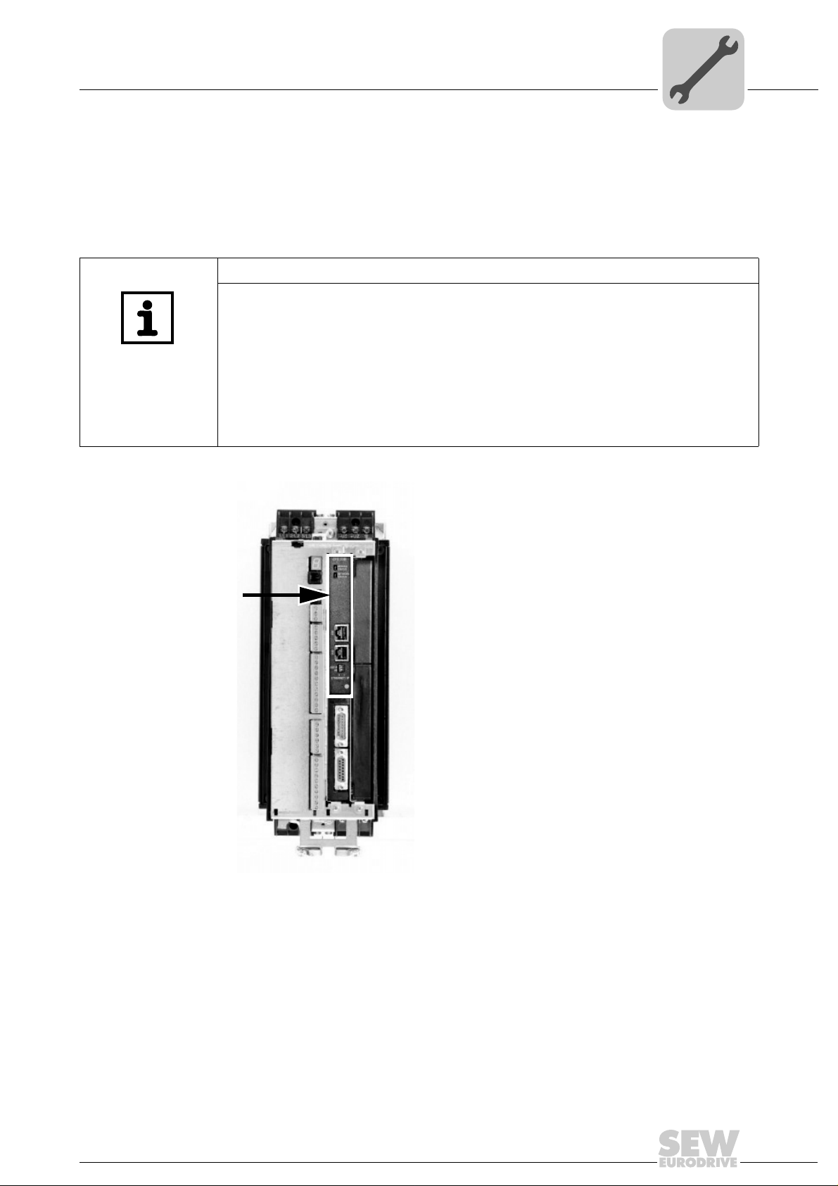
4.1 Installing the DFE33B option card in MOVIDRIVE® MDX61B
TIPS
• Only SEW-EURODRIVE personnel may install or remove option cards for
MOVIDRIVE
• Users may only install or remove option cards for MOVIDRIVE
sizes 1 to 6.
• Plug the DFE33B EtherNet/IP option card into the fieldbus slot [1].
• Only use connectors and cables approved for EtherNet/IP when cabling.
• The DFE33B option is supplied with voltage via MOVIDRIVE
voltage supply is not required.
®
MDX61B size 0.
®
MDX61B
®
B. A separate
[1]
62180AXX
Manual – Fieldbus Interface DFE33B EtherNet/IP and Modbus/TCP
11
Page 12

4
Phone: 800.894.0412 - Fax: 888.723.4773 - Web: www.clrwtr.com - Email: info@clrwtr.com
4.1.1 Before you begin
Assembly and Installation Instructions
Installing the DFE33B option card in MOVIDRIVE® MDX61B
Observe the following notes before installing or removing an option card:
• Disconnect the inverter from the power. Switch off the DC 24 V and the supply
voltage.
• Take appropriate measures to protect the option card from electrostatic charge
(use discharge strap, conductive shoes, and so on) before touching it.
• Before installing the option card, remove the keypad and the front cover
(see MOVIDRIVE
• After having installed the option card, replace the keypad and the front cover
(see MOVIDRIVE
• Keep the option card in its original packaging until immedi ately before you ar e ready
to install it.
• Hold the option card by its edges only. Do not touch any components.
®
MDX60B/61B operating instructions, section "Installation").
®
MDX60B/61B operating instructions, section "Installation").
12
Manual – Fieldbus Interface DFE33B EtherNet/IP and Modbus/TCP
Page 13
Assembly and Installation Instructions
Phone: 800.894.0412 - Fax: 888.723.4773 - Web: www.clrwtr.com - Email: info@clrwtr.com
Installing the DFE33B option card in MOVIDRIVE® MDX61B
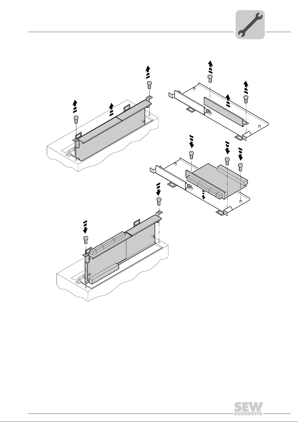
4.1.2 Basic procedure for installing/removing an option card (MDX61B, sizes 1 – 6)
2.
1.
1.
3.
3.
4
2.
3.
4.
4.
60039AXX
1. Remove the two retaining screws holding the card retaining bracket. Pull the card
retaining bracket out evenly from the slot (do not twist !).
2. Remove the two retaining screws of the black cover plate on the card retaining
bracket. Remove the black cover plate.
3. Position the option card onto the retaining bracket so that the three retaining screws
fit into the corresponding bores on the card retaining bracket.
4. Insert the retaining bracket with installed option card into the slot, pressing slightly so
it is seated properly. Secure the card retaining bracket with the two retaining screws.
5. To remove the option card, follow the instructions in reverse order.
Manual – Fieldbus Interface DFE33B EtherNet/IP and Modbus/TCP
13
Page 14
4
X45
X46
1
23456HL ⊥
FSC11B
S1
OFF
ON
7
S2
X44
X26
1234567
X24
H1
H2
X12
1
2
3
4
5
6
7
8
24V IO
DC 24 V
–
+
9
GND
=
DFE 33B
X30X32
Def IP
ETHERNET/IP
AS
01
MODULE
STATUS
NETWORK
STATUS
MAC ID:
00-0F-69-00-02-0B
IP:
[1]
[2]
Phone: 800.894.0412 - Fax: 888.723.4773 - Web: www.clrwtr.com - Email: info@clrwtr.com
Assembly and Installation Instructions
Installing the DFE33B option card in MOVITRAC® B
4.2 Installing the DFE33B option card in MOVITRAC® B
TIP
Only SEW-EURODRIVE engineers are allowed to install or remove option cards for
MOVITRAC
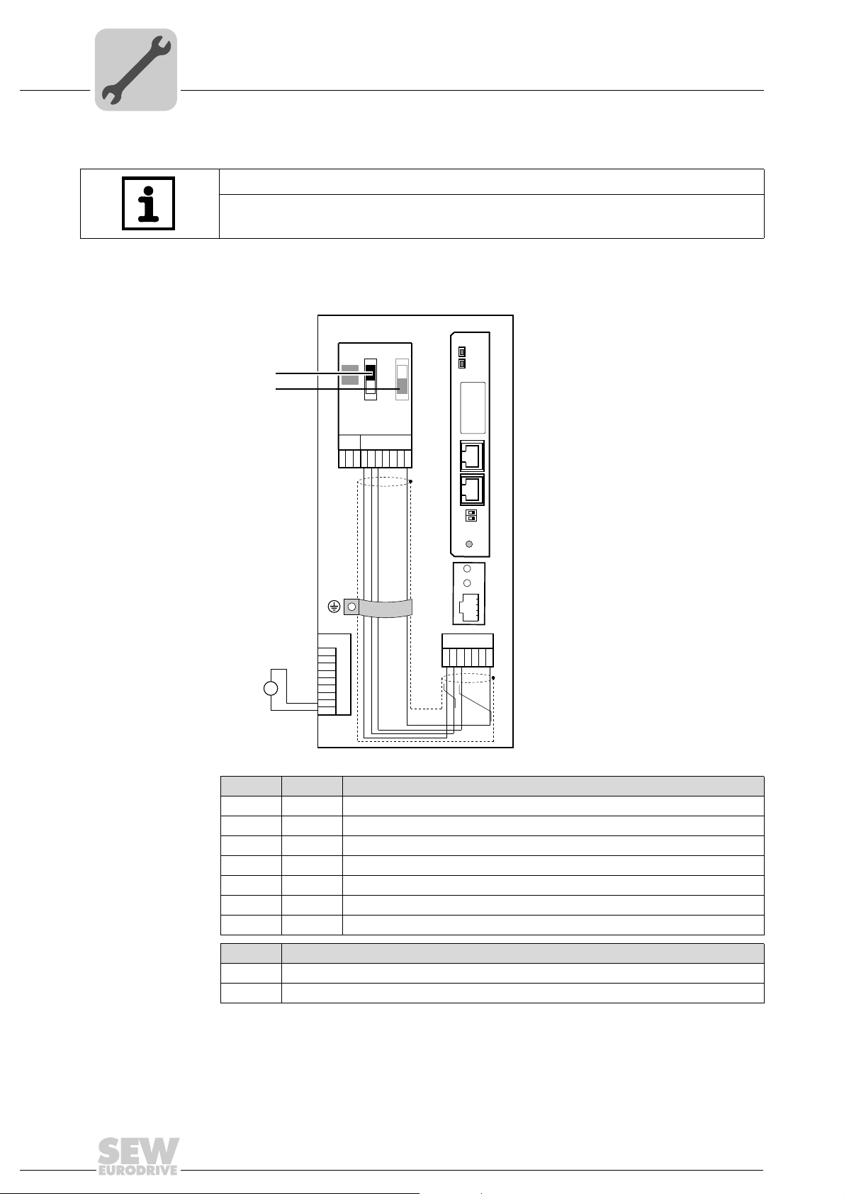
4.2.1 Connecting the system bus between a MOVITRAC® B unit and the DFE33B option
®
B.
[1] Terminating resistor activated, S1 = ON
[2] DIP switch S2 (reserved), S2 = OFF
14
62135AXX
X46 X26 Terminal assignment
X46:1 X26:1 SC11 SBus +, CAN high
X46:2 X26:2 SC12 SBus –, CAN low
X46:3 X26:3 GND, CAN GND
X46:6 X26:6 GND, CAN GND
X26:4 Reserved
X26:5 Reserved
X46:7 X26:7 DC 24 V
X12 Terminal assignment
X12:8 DC+24 V input
X12:9 GND reference potential for binary inputs
To simplify cabling, the DFE33B option can be supplied with DC 24 V from X46.7 of the
MOVITRAC
X12.8 and X12.9 when it supplies the DFE33B option. Activate the system bus termi-
®
B to X26.7. MOVITRAC® B must be supplied with DC 24 V at terminals
nating resistor at the FSC11B option (S1 = ON).
Manual – Fieldbus Interface DFE33B EtherNet/IP and Modbus/TCP
Page 15
Assembly and Installation Instructions
Phone: 800.894.0412 - Fax: 888.723.4773 - Web: www.clrwtr.com - Email: info@clrwtr.com
Installing the DFE33B option card in MOVITRAC® B
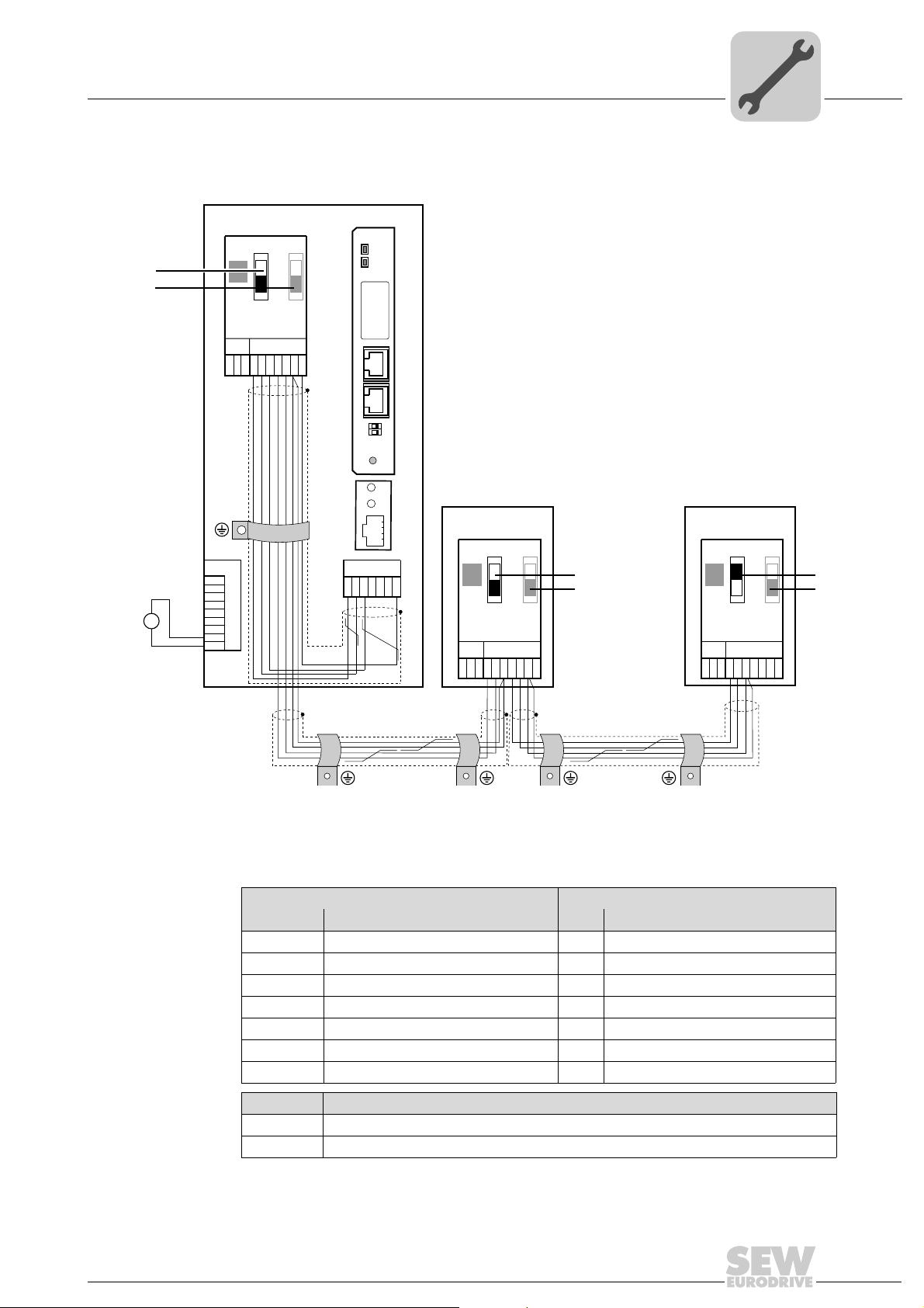
4.2.2 Connecting the system bus between several MOVITRAC® B units
4
DC 24 V
[1]
[2]
MOVITRAC® B
DFE 33B
S1
S2
ON
OFF
X44
FSC11B
X46
X45
7
23456HL^
1
X12
1
2
3
+
=
-
24V IO
GND
4
5
6
7
8
9
MODULE
STATUS
NETWORK
STATUS
MAC ID:
00-0F-69-00-02-0B
IP:
X30X32
Def IP
AS
01
ETHERNET/IP
H1
H2
X24
X26
1234567
MOVITRAC® B
S1
ON
OFF
X44
FSC11B
X46
X45
23456HL ^
1
S2
MOVITRAC® B
S1
S2
X44
ON
OFF
[1]
[2]
[1]
[2]
FSC11B
X46
X45
7
23456HL ^
1
7
[1] Only the terminating resistor at the last unit is activated, S1 = ON
[2] DIP switch S2 (reserved), S2 = OFF
MOVITRAC® B DFE33B in the UOH11B gateway housing
X46 Terminal assignment X26 Terminal assignment
X46:1 SC11 (System bus high, incoming) X26:1 SC11 SBus +, CAN high
X46:2 SC12 (System bus low, incoming) X26:2 SC12 SBus –, CAN low
X46:3 GND (System bus reference) X26:3 GND, CAN GND
X46:4 SC21 (System bus high, outgoing) X26:4 Reserved
X46:5 SC22 (System bus low, outgoing) X26:5 Reserved
X46:6 GND (System bus reference) X26:6 GND, CAN GND
X46:7 DC 24 V X26:7 DC 24 V
X12 Terminal assignment
X12:8 DC+24 V input
X12:9 GND reference potential for binary inputs
62136AXX
Manual – Fieldbus Interface DFE33B EtherNet/IP and Modbus/TCP
15
Page 16
4
Phone: 800.894.0412 - Fax: 888.723.4773 - Web: www.clrwtr.com - Email: info@clrwtr.com
Assembly and Installation Instructions
Installing the DFE33B option card in MOVITRAC® B
Please note:
• Use a 2x2 core twisted and shielded copper cable (data transmission cable with
braided copper shield). Connect the shield flatly on both sides of the electronics
shield clamp of MOVITRAC
must meet the following specifications:
– Core cross section 0.25 mm
– Cable resistance 120 Ê at 1 MHz
– Capacitance per unit length  40 pF/m at 1 kHz
Suitable cables are CAN bus or DeviceNet cables.
• The permitted total cable length is 100 m (328 ft). The SBus baud rate has a fixed
setting of 500 kBaud.
• Connect the system bus terminating resistor (S1 = ON) at the end of the system bus
connection. Switch off the terminating resistor on the other units (S1 = OFF). The
DFE33B gateway must always be connected either at the beginning o r the end of the
system bus connection. The terminating resistor is permanently installed.
®
. Also connect the ends of the shield to GND. The cable
2
(AWG18) to 0.75 mm2 (AWG23)
TIPS
• There must not be any potential displacement between the units connected with the
SBus. Take suitable measures to avoid potential displacement, such as connecting
the unit ground connectors using a separate cable.
• Point-to-point SBus wiring is not permitted.
16
Manual – Fieldbus Interface DFE33B EtherNet/IP and Modbus/TCP
Page 17
Assembly and Installation Instructions
X26
1
23456
7
SEW Drive
UOH11B
DC+24 V
GND
X24
H1
H2
SC11 system bus +, CAN high
SC12 system bus -, CAN low
GND, CAN GND
DFE 33B
X30X32
Def IP
ETHERNET/IP
AS
01
MODULE
STATUS
NETWORK
STATUS
MAC ID:
00-0F-69-00-02-0B
IP:
Phone: 800.894.0412 - Fax: 888.723.4773 - Web: www.clrwtr.com - Email: info@clrwtr.com
Installing the DFE33B gateway / UOH11B
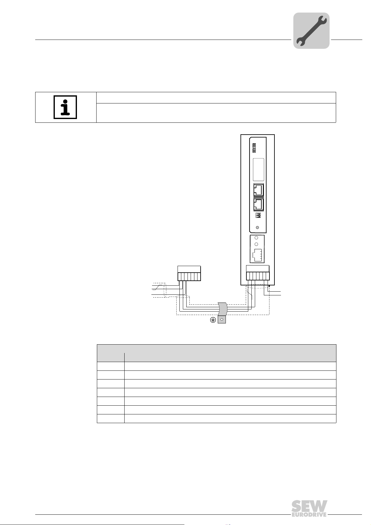
4.3 Installing the DFE33B gateway / UOH11B
The following figure shows the connection of the DFE33B option via the UOH11B
gateway housing.
TIP
Only SEW-EURODRIVE engineers are allowed to install or remove option cards
in/from the UOH11B gateway housing.
4
Manual – Fieldbus Interface DFE33B EtherNet/IP and Modbus/TCP
UOH11B gateway housing
X26 Terminal assignment
X26:1 SC11 system bus +, CAN high
X26:2 SC12 system bus –, CAN low
X26:3 GND, CAN GND
X26:4 Reserved
X26:5 Reserved
X26:6 GND, CAN GND
X26:7 DC 24 V
The gateway housing requires a power supply of DC 24 V that is connected to X26.
Connect the system bus terminating resistor at the end of the system bus connection.
62137AEN
17
Page 18
4
Phone: 800.894.0412 - Fax: 888.723.4773 - Web: www.clrwtr.com - Email: info@clrwtr.com
Assembly and Installation Instructions
Connection and terminal description of the DFE33B option
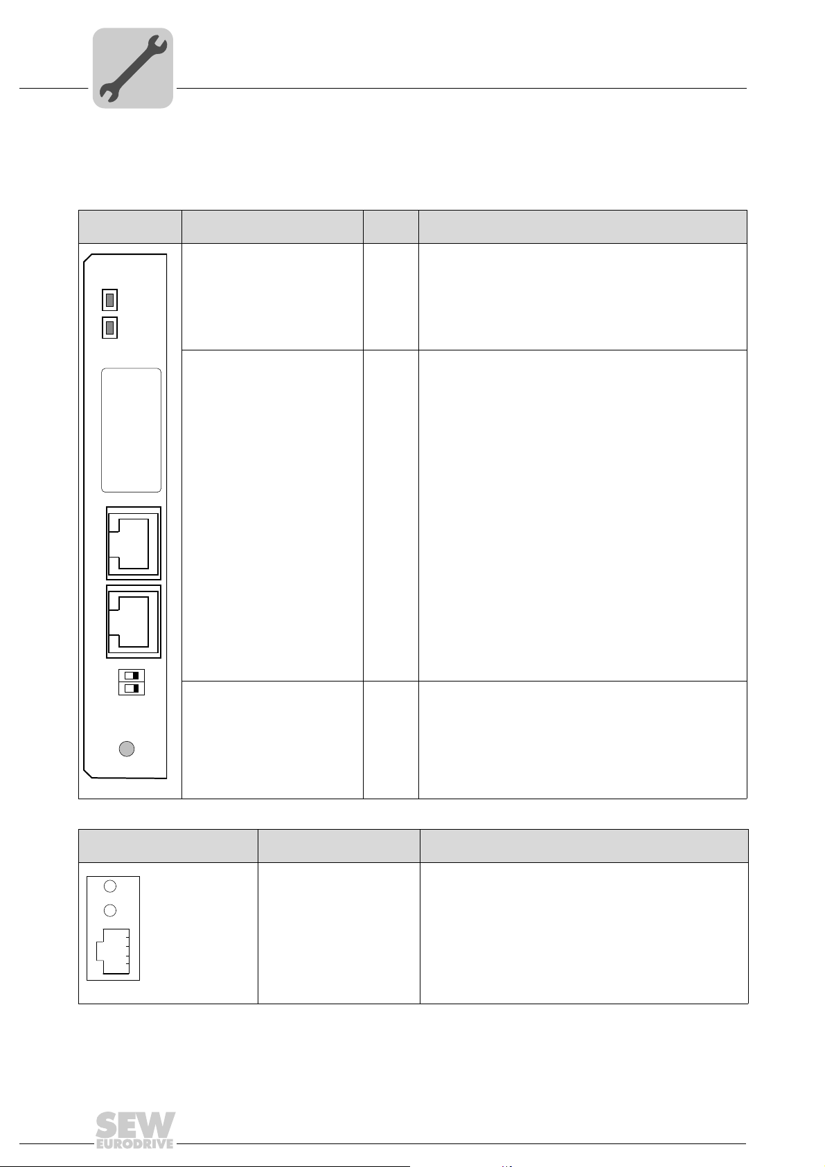
4.4 Connection and terminal description of the DFE33B option
Part number EtherNet/IP and Modbus/TCP fieldbus interface option type DFE33B: 1821 346 4
Front view of
DFE33B
DFE 33B
MODULE
STATUS
NETWORK
STATUS
MAC ID:
00-0F-69-xx-xx-xx
X30X32
Description
MODULE STATUS LED
(red/green)
NETWORK STATUS LED
(red/green)
MAC address
IP input field
IP:
X30: Ethernet connection
Link LED (green)
Activity LED (yellow)
DIP
switch
Function
Shows the current status of the DFE33B option.
Shows the status of the controlling EtherNet/IP or Modbus/TCP
connection.
MAC address, e.g. to configure the DHCP server.
You can enter the allocated IP address in this field.
X32: Ethernet connection
Link LED (green)
Activity LED (yellow)
Def IP
AS
01
ETHERNET/IP
62138AXX
Front view of MOVITRAC®B
and UOH11B
H1
H2
X24
DIP switch DEF IP Resets the address parameters to their default values and
58129AXX
deactivates DHCP
• IP address: 192.168.10.4
• Subnetwork mask: 255.255.255.0
• Gateway: 1.0.0.0
AS Auto Setup for gateway operation
Description Function
LED H1 (red)
LED H2 (green)
X24 X terminal
System bus error (only for gateway functions)
Reserved
RS485 interface for diagnostics via PC and MOVITOOLS
MotionStudio (only for MOVITRAC
®
®
B)
18
Manual – Fieldbus Interface DFE33B EtherNet/IP and Modbus/TCP
Page 19
Assembly and Installation Instructions
Phone: 800.894.0412 - Fax: 888.723.4773 - Web: www.clrwtr.com - Email: info@clrwtr.com
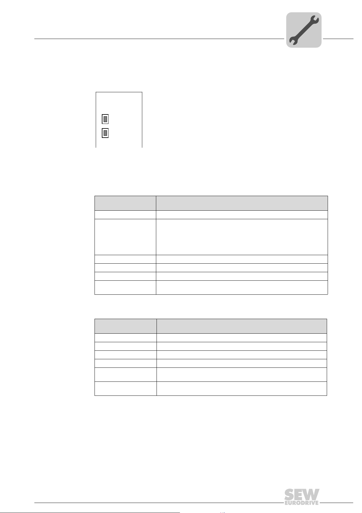
4.5 Status LED of the DFE33B option
The LEDs of the DFE33B option card indicate the current status of the DFE33B option
and the fieldbus system.
DFE33B
MODULE
STATUS
NETWORK
STATUS
The fieldbus interface status indicated by the respective status LED is summarized in
the section "Troubleshooting".
Status LED of the DFE33B option
4
62139AXX
MODULE
STATUS LED
NETWORK
STATUS LED
The MODULE STATUS LED indicates that the bus electronics are operating correctly.
States of the
MODULE STATUS LED
Off The DFE33B option card is not supplied with voltage or is defective
Flashing green • If the NETWORK STATUS LED is off at the same time, the TCP/IP stack
Flashing green/red The DFE33B option card performs a LED test.
Green The standard operating state of the DFE33B option card.
Red The DFE33B option card is in fault state.
Flashing red A conflict has been detected in the IP address assignment. Another station in
Meaning
of the DFE33B option card will be started. If this status continues and
DHCP is activated, the DFE33B option card waits for data from the DHCP
server.
• If the NETWORK STATUS LED is flashing green at the same time,
the application of the DFE33B option card is started.
the network uses the same IP address.
The NETWORK STATUS LED indicates the state of the fieldbus system.
States of the
NETWORK STATUS LED
Off The DFE33B option does not yet have any IP parameters.
Flashing green/red The DFE33B option card performs a LED test.
Flashing green There is no controlling IO connection.
Green There is a controlling EtherNet/IP or Modbus/TCP connection.
Red A conflict has been detected in the IP address assignment.
Flashing red The previously established controlling IO connection is in timeout status.
Meaning
Another station in the network uses the same IP address.
The status is reset by restarting communication.
Manual – Fieldbus Interface DFE33B EtherNet/IP and Modbus/TCP
19
Page 20
4
X24
H1
H2
Phone: 800.894.0412 - Fax: 888.723.4773 - Web: www.clrwtr.com - Email: info@clrwtr.com
Assembly and Installation Instructions
Status LED of the DFE33B option
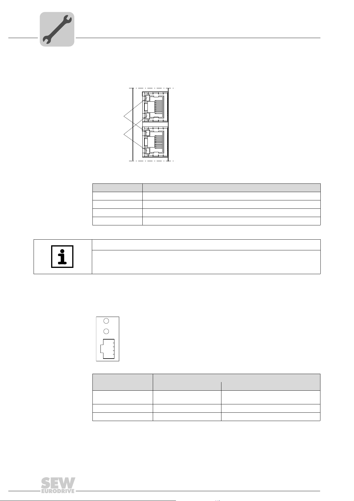
Link/Activity LED The two LEDs Link (green) and Activity (yellow), integrated in the RJ45 plug connec-
tors (X30, X32), display the status of the Ethernet connection.
LED "Link"
LED "Activity"
LED / status Meaning
Link / green There is an Ethernet connection.
Activity / yellow Data is currently being exchanged via Ethernet.
Link / off There is no Ethernet connection.
Link (X30) / flashes Locating function of Address Editor (see section 10)
X30
X32
61880AXX
TIP
As the firmware of the DFE33B option card takes approx. 15 second s fo r initialization,
the status "0" (inverter not ready) is displayed in the 7-segment display of
MOVIDRIVE
®
during this time.
4.5.1 Gateway LED
LEDs H1 and H2 indicate the communication status in gateway operation.
58129AXX
LED H1 Sys-fault (red) Only for gateway operation
Status State Description
Red System bus error Gateway not configured or one of the drives
is inactive
Off SBus ok Gateway is configured correctly
Flashing Bus scan Bus is being checked by the gateway
•LED H2 (green) is currently reserved.
• X-terminal X24 is the RS485 interface for diagnostics via PC and MOVITOOLS
MotionStudio.
®
20
Manual – Fieldbus Interface DFE33B EtherNet/IP and Modbus/TCP
Page 21
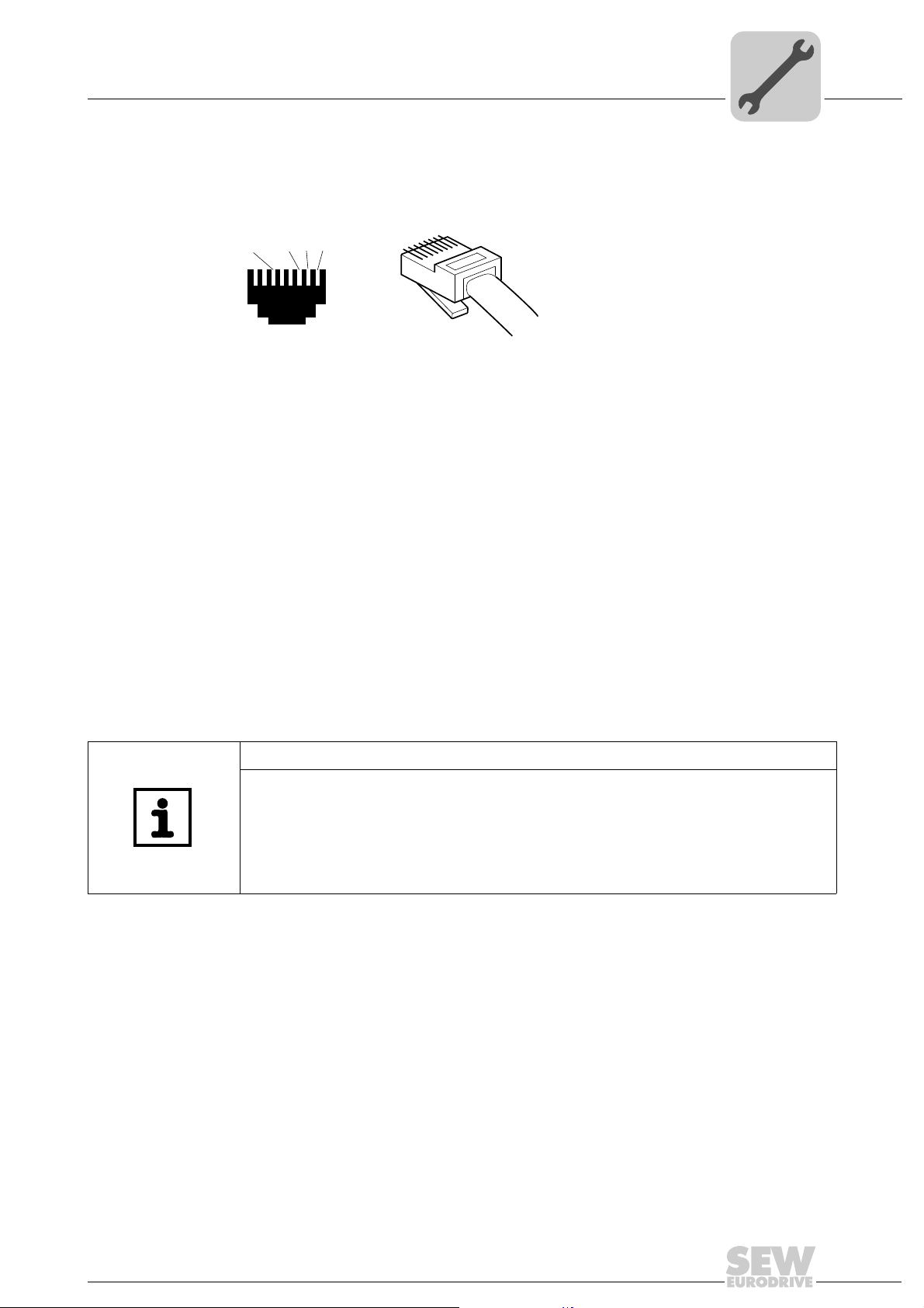
4.6 Pin assignment
Phone: 800.894.0412 - Fax: 888.723.4773 - Web: www.clrwtr.com - Email: info@clrwtr.com
Use prefabricated, shielded RJ45 plug connectors compliant with IEC 11801 edition 2.0,
category 5.
[6]
Fig. 1: Pin assignment of an RJ45 plug connector
A = Front view
B = View from back
[1] Pin 1 TX+ Transmit Plus
[2] Pin 2 TX– Transmit Minus
[3] Pin 3 RX+ Receive Plus
[6] Pin 6 RX– Receive Minus
Assembly and Installation Instructions
Pin assignment
[1]
[2]
[3]
AB
6
3
2
1
4
54174AXX
MOVIDRIVE
®
/ MOVITRAC® B / Ethernet connection
To connect DFE33B to the Ethernet, connect the Ethernet interface X30 or X32 (RJ45
plug connector) to the other network stations using a category 5, class D twisted-pair
cable in accordance with IEC 11801 edition 2.0. The integrated switch provides support
for achieving a line topology and offers auto-crossing functions.
TIPS
• According to IEC 802.3, the maximum cable length for 10/100 MBaud Ethernet
(10BaseT / 100BaseT), e.g. between two network stations, is 100 m.
• We recommend that you do not directly connect terminals to the DFE33B optio n in
order to minimize the load on the terminals caused by undesired multicast data
traffic in EtherNet/IP networks. Connect non-SEW devices via a networ k component that supports the IGMP snooping functionality (e.g. managed switch).
Manual – Fieldbus Interface DFE33B EtherNet/IP and Modbus/TCP
21
Page 22
4
Phone: 800.894.0412 - Fax: 888.723.4773 - Web: www.clrwtr.com - Email: info@clrwtr.com
Assembly and Installation Instructions
The integrated Ethernet switch
4.7 The integrated Ethernet switch
You can use the integrated Ethernet switch to achieve line topologies known from the
fieldbus technology. Other bus topologies such as star or tree are, of course, also
possible. Ring topologies are not supported.
TIP
The number of industrial Ethernet switches connected in line affects the telegram
runtime. If a telegram passes through the units, the telegram runtime is delayed by the
Store & Forward function of the Ethernet switch:
• for a telegram length of 64 bytes by approximately 10 µs (at 100 Mbit/s)
• for a telegram length of 1500 bytes by approximately 130 µs (at 100 Mbit/s)
This means, the more units that the telegram has to run through, the longer the telegram runtime.
Auto-crossing The two ports leading out of the Ethernet switch have auto-crossing functionality. This
means you can use both patch cables and cross-over cables to connect to the next
Ethernet station.
Autonegotiation The baud rate and the duplex mode is negotiated by both Ethernet nodes when estab-
lishing the connection. The two Ethernet ports of the EtherNet/IP interface support autonegotiation functionality and operate at a baud rate of 100 Mbit or 10 Mbit in full duplex
or half duplex mode.
Notes on
multicast
handling
• The integrated Ethernet switch offers no filter functionality for Ethernet multicast telegrams. Multicast telegrams that are usually sent from the adapters (DFE33B) to the
scanners (PLC) are passed on to all switch ports.
• IGMP snooping (e.g. managed switches) is not supported.
• SEW-EURODRIVE therefore recommends to connect the DFE33B option only with
network components that support IGMP snooping (e .g. managed switch) or that have
safety mechanisms integrated against excess multicast load (e.g. units from SEWEURODRIVE). Units that do not have this integrated function can fail due to high
network loads.
4.8 Shielding and routing bus cables
Only use shielded cables and connection elements that also meet the requirements of
category 5, class 2 in compliance with IEC 11801 edition 2.0.
Correct shielding of the bus cable atte nuates electrical interference that can occur in
industrial environments. The following measures ensure the best possible shielding:
• Manually tighten the mounting screws on the connectors, modules, and equipotential
bonding conductors.
• Use only connectors with a metal housing or a metallic housing.
• Connect the shielding in the connector over a wide surface area.
• Apply the shielding of the bus line on both ends.
• Route signal and bus cables in separate cable ducts. Do not route them parallel to
power cables (motor leads).
22
Manual – Fieldbus Interface DFE33B EtherNet/IP and Modbus/TCP
Page 23
• Use metallic, grounded cable racks in industrial environments.
Phone: 800.894.0412 - Fax: 888.723.4773 - Web: www.clrwtr.com - Email: info@clrwtr.com
• Route the signal cable and the corresponding equipotential bonding close to each
other using the shortest possible route.
• Avoid using plug connectors to extend bus cables.
• Route the bus cables closely along existing grounding surfaces.
STOP!
In case of fluctuations in the ground potential, a comp ensating current may flow via the
bilaterally connected shield that is also connected to the protective earth (PE). Make
sure you supply adequate equipotential bonding in accordance with relevant VDE
regulations in such a case.
4.9 Setting the DIP switches
TIP
The setting of the "Def IP" DIP switch is only adopted with a power-on reset (switchi ng
mains and DC 24 V backup voltage on and off).
Assembly and Installation Instructions
Setting the DIP switches
4
Def IP When the "Def IP" switch is set to "1" (= ON), the following default IP address parame-
ters are set when activating the DC 24 V backup voltage:
• IP address: 192.168.10.4
• Subnetwork mask: 255.255.255.0
• Default gateway: 1.0.0.0
• P785 DHCP / Startup configuration: Saved IP parameters (DHCP is deactivated)
AS The "AS" DIP switch is used to configure the SBus communication of the gateway
(see section "Auto Setup for gateway operation").
The configuration becomes active when the "AS" DIP switch is set from "0" to "1".
To continue operation, the "AS" DIP switch must remain in the "1" position (= ON).
Manual – Fieldbus Interface DFE33B EtherNet/IP and Modbus/TCP
23
Page 24
4
Phone: 800.894.0412 - Fax: 888.723.4773 - Web: www.clrwtr.com - Email: info@clrwtr.com
Assembly and Installation Instructions
TCP/IP addressing and subnetworks
4.10 TCP/IP addressing and subnetworks
Introduction The settings for the address of the IP protocol are made using the following parameters:
• MAC address
• IP address
• Subnetwork mask
• Standard gateway
The addressing mechanisms and subdivision of the IP networks into subnetworks are
explained in this chapter to help you set the parameters correctly.
MAC address The MAC address (Media Access Controller) is the basis for all address settings. The
MAC address is a worldwide unique 6-byte value (48 bits) assigned to the Ethernet
device. SEW Ethernet devices have the MAC address 00-0F-69-xx-xx-xx. The MAC
address is difficult to handle for larger networks. This is why freely assignable IP
addresses are used.
IP address The IP address is a 32 bit value that uniquely identifies a station in the network. An IP
address is represented by four decimal numbers separated by decimal points.
Example: 192.168.10.4
Each decimal number stands for one byte (= 8 bits) of the address and can also be
represented using binary code (Æ following table).
Byte 1 Byte 2 Byte 3 Byte 4
11000000 . 10101000 . 00001010 . 00000100
The IP address comprises a network address and a station address ( Æ following table).
Network address Station address
192.168.10 4
The part of the IP address that denotes the network and the part that identifies the
station is determined by the network class and the subnetwork mask.
Station addresses cannot consist of only zeros or ones ( binary) because they represent
the network itself or a broadcast address.
Network classes The first byte of the IP address determine s the network class and as such repres ents
the division into network addresses and station addresses.
Value range
Byte 1
0 ... 127 A 10.1.22.3 10 = Network address
128 ... 191 B 172.16.52.4 172.16 = Network address
192 ... 223 C 192.168.10.4 192.168.10 = Network address
Network class
Complete network address
(Example)
Meaning
1.22.3 = Station address
52.4 = Station address
4 = Station address
This rough division is not sufficient for a number of networks. They also use an explicit,
adjustable subnet mask.
24
Manual – Fieldbus Interface DFE33B EtherNet/IP and Modbus/TCP
Page 25
Assembly and Installation Instructions
Phone: 800.894.0412 - Fax: 888.723.4773 - Web: www.clrwtr.com - Email: info@clrwtr.com
TCP/IP addressing and subnetworks
4
Subnetwork
mask
A subnetwork mask is used to divide the network classes into even more precisely
defined subsections. The subnetwork mask is represented by four decimal numbers
separated by decimal points, in the same way as the IP ad dr es s.
Example: 255.255.255.128
Each decimal number stands for one byte (= 8 bits) of the subnetwork mask and can
also be represented using binary code (Æ following table).
Byte 1 Byte 2 Byte 3 Byte 4
11111111 . 11111111 . 11111111 . 10000000
If you compare the IP addresses with the subnetwork masks, you se e that in th e bi nar y
representation of the subnetwork mask all ones (1s) deter mine the network address and
all the zeros (0s) determine the station address (Æ following table).
Byte 1 Byte 2 Byte 3 Byte 4
IP address
Subnetwork mask
Decimal 192 . 168. . 10 . 129
Binary 11000000 . 10101000 . 00001010 . 10000001
Decimal 255 . 255 . 255 . 128
Binary 11111111 . 11111111 . 11111111 . 10000000
The class C network with the address 192.168.10. is further subdivided into
255.255.255.128 using the subnetwork mask. Two networks are created with the
address 192.168.10.0 and 192.168.10.128.
The following station addresses are permitted in the two networks:
• 192.168.10.1 ... 192.168.10.126
• 192.168.10.129 ... 192.168.10.254
The network stations use a logical AND operation for the IP address and the subnetwor k
mask to determine whether there is a communication partner in the same network or in
a different network. If the communication partner is in a different network, the standard
gateway is addressed for passing on the data.
Standard gateway The standard gateway is also addressed via a 32-bit address. The 32-bit address is
represented by four decimal numbers separated by decimal points.
Example: 192.168.10.1
The standard gateway establishes a connection to other networks. In this way, a net-
work station that wants to address another station can use a logical AND operation with
the IP address and the subnetwork mask to decide whether the desired station is located
in the same network. If this is not the case, the station addresses the standard gateway
(router), which must be part of the actual network. The standard gateway th en takes on
the job of transmitting the data packages.
DHCP
(Dynamic Host
Configuration
Protocol)
Instead of setting the three parameters IP address, subnetwork mask and standard
gateway manually, they can be assigned in an automated manne r by a DHCP server in
the Ethernet network.
This means the IP address is assigned from a table, which contains the allocation of
MAC address to IP address.
Parameter P785 indicates whether the DFE33B option expects the IP p arameters to be
assigned manually or via DHCP.
Manual – Fieldbus Interface DFE33B EtherNet/IP and Modbus/TCP
25
Page 26
4
Phone: 800.894.0412 - Fax: 888.723.4773 - Web: www.clrwtr.com - Email: info@clrwtr.com
Assembly and Installation Instructions
Setting the IP address parameters
4.11 Setting the IP address parameters
Initial startup The "DHCP" protocol (Dynamic Host Configuration Protocol) is activated as the default
setting for the DFE33B protocol. This means that the DFE33B option card expects its IP
address parameters from a DHCP server.
TIP
Rockwell Automation provides a DHCP server free-of-charge on their homepage.
The tool is known as "BOOTP Utility" and can be downloaded at the link below:
Once the DHCP server has been configured and the settings have been made for the
subnetwork screen and the standard gateway, the DFE33B must be inserted in the
assignment list of the DHCP server. In doing so, the MAC ID of the DFE33B option is
allocated a valid IP address.
TIP
The configured IP address parameters are adop ted perman ently by the pa rameter set
when DHCP is deactivated after the IP address has been assigned.
Changing the
IP address
parameters after
successful initial
startup
If the DFE33B was started using a valid IP address, you can also access the IP ad dress
parameters via the Ethernet interface.
The following options are available for changing the IP address parameters via Ethernet:
• Via the homepage of DFE33B (see section "Integrated Web Server")
®
• Using the MOVITOOLS
"MOVITOOLS
• Using the EtherNet/IP TCP/IP interface object (see section "EtherNet/IP CIP object
directory")
You can also change the IP address parameters via the serial interface of the gateway
or MOVIDRIVE
If the IP address parameters are assigned to the option DFE33 B via a DHCP server, you
can only change the parameters by adjusting the settings of the DHCP server.
The options listed above for changing the IP address parameters only come into effect
once the supply voltages (mains and DC 24 V) have been switched off and back on
again.
®
MotionStudio via Ethernet")
®
MDX61B or using the DBG60B keypad (in MOVIDRIVE® B).
MotionStudio software via Ethernet (see section
26
Manual – Fieldbus Interface DFE33B EtherNet/IP and Modbus/TCP
Page 27

Assembly and Installation Instructions
Phone: 800.894.0412 - Fax: 888.723.4773 - Web: www.clrwtr.com - Email: info@clrwtr.com
Setting the IP address parameters
4
Deactivating /
activating the
DHCP
Resetting the
IP address
parameters
The type of IP address assignment is determined by the setting of the attribute
Configuration Control of the EtherNet/IP TCP/IP interface object. The value is displayed
or changed in the parameter P785 DHCP / Startup Configuration.
• Setting "Saved IP parameters"
The saved IP address parameters are used.
• Setting "DHCP"
The IP address parameters are requested by a DHCP server.
If you use the DHCP server from Rockwell Automation, you can activate or deacti-
vate the DHCP via a button. In this case, an EtherNet/IP telegram is sent to the
TCP/IP interface object of the station that is being addr es sed .
If you do not know the IP address parameters and there is no serial interface or DBG60B
keypad for reading the IP address, you can reset the IP address parameters to the
default values using the DIP switch "Def IP".
This action resets the DFE33B option to the following default values:
• IP address: 192.168.10.4
• Subnetwork mask: 255.255.255.0
• Default gateway: 1.0.0.0
• P785 DHCP / Startup configuration: Saved IP parameters (DHCP is deactivated)
SEW Address
Editor
Proceed as follows to reset the IP address parameters to the default values:
• Switch off the DC 24 V supply voltage and the mains voltage.
• Set the DIP switch "Def IP" on the DFE33B option to "1".
• Switch the DC 24 V supply voltage and the mains voltage back on.
To access the IP settings of the DFE33B interfaces without the Ethernet settings of the
PC and DFE33B having to match, the SEW Address Editor can be used if firmware
version .11 or higher is installed on the DFE33B.
The IP settings of all SEW units can be made and displayed in the local subnetwork
using Address Editor (see section 10).
• This allows the required settings for the PC to be determined for an installation which
is in operation to enable access with the required diagnostics and engineering tools
via Ethernet.
• When starting up a unit, the IP settings for the DFE33B can be assigned without
changing the network connections or PC settings.
TIP
• DHCP remains deactivated when you reset the DIP switch "Def IP" to "0". You
can re-activate DHCP via the EtherNet/IP TCP/IP interface object (see section
"EtherNet/IP CIP object directory"), via the parameter P785, via the integrated web
server or via the DHCP server from Rockwell.
• DHCP is not activated again when the values are reset to the factory setting
(P802 Factory setting).
Manual – Fieldbus Interface DFE33B EtherNet/IP and Modbus/TCP
27
Page 28

4
Phone: 800.894.0412 - Fax: 888.723.4773 - Web: www.clrwtr.com - Email: info@clrwtr.com
Assembly and Installation Instructions
Procedure for replacing the unit
4.12 Procedure for replacing the unit
If the DIP switch "Def IP" of the DFE33B option is set to "1" (= ON), the DIP switch "Def
IP" on the new DFE33B must also be set to "1" (= ON) (after the option card has been
replaced or after the MOVIDRIVE
been replaced with an option card). Other IP parameter settings are not req uired.
If the DIP switch "Def IP" of the DFE33B option is set to "0" (= OFF), it is important that
you observe the following section when replacing the option card or a unit with option
card:
• Section "Replacing MOVIDRIVE
• Section "Replacing MOVITRAC
®
4.12.1 Replacing MOVIDRIVE
B
®
B / MOVITRAC® B / gateway housing unit have each
®
B"
®
B / gateway"
When the DFE33B fieldbus interface is operated as an option card in MOVIDRIVE
®
B,
the procedure for replacement depends on the following factors:
• Whether DHCP is activated or a saved IP address is used
• Whether the memory card of the replaced MOVIDRIVE
®
MDX61B is plugged into the
new unit or not
If DHCP is active, the assignment list of the DHCP server mus t be updated when the
DFE33B option or MOVIDRIVE
®
B with DFE33B option is replaced. The MAC address
of the DFE33B option is printed on its front panel for this purpose.
If DHCP is not active, the IP parameters saved on the memory card of MOVIDRIVE
®
B
will be used.
If the memory card of MOVIDRIVE
®
B is not plugged into the new unit when replacing
it, you will have to perform complete startup of the new inverter (if DHCP is not active
including the IP parameters). As an alternative, you can tran sfe r a da ta ba ckup cre ated
with the MOVITOOLS
®
MotionStudio software or saved in the DBG60B keypad.
Enter the IP address, which is set in the DFE33B or defined in the assignmen t list of the
DHCP server, into the field on the front panel of the DFE33B option for future diagnostic
or engineering work.
28
Manual – Fieldbus Interface DFE33B EtherNet/IP and Modbus/TCP
Page 29

Assembly and Installation Instructions
Phone: 800.894.0412 - Fax: 888.723.4773 - Web: www.clrwtr.com - Email: info@clrwtr.com
4.12.2 Replacing MOVITRAC® B / gateway
Procedure for replacing the unit
4
If the DFE33B fieldbus interface is operated as an option card in MOVITRAC
the UOH11B gateway housing, the procedure for replacement dep ends on the following
factors:
• Whether DHCP is activated or a saved IP address is used
• Whether the DFE33B option is installed in MOVITRAC
If DHCP is active, the assignment list of the DHCP server mus t be updated when the
DFE33B option or MOVITRAC
of the DFE33B option is printed on its front panel for this purpose.
If DHCP is not active, the IP parameters saved non-volatile on the DFE33B option will
be used. Set the IP parameters just as for initial startup. As an alternative , you can copy
a parameter file saved with MOVITOOLS
pack 2) to the DFE33B option or use the Address
Editor to set the IP parameters.
If a MOVITRAC
to be performed in addition to setting the IP parameters. Refer to the MOVITRAC
operating instructions for more information.
Enter the IP address, which is set in the DFE33B or defined in the assignmen t list of the
DHCP server, into the field on the front panel of the DFE33B option for future diagnostic
or engineering work.
®
B with DFE33B was replaced by a new unit, inverter startup will have
®
B with DFE33B option is replaced. The MAC address
®
MotionStudio (from version 5.50, service
®
B or in the gateway housing
®
B or in
®
B
Manual – Fieldbus Interface DFE33B EtherNet/IP and Modbus/TCP
29
Page 30
5
Phone: 800.894.0412 - Fax: 888.723.4773 - Web: www.clrwtr.com - Email: info@clrwtr.com
Project Planning and Startup (EtherNet/IP)
Validity of the EDS file for DFE33B
5 Project Planning and Startup (EtherNet/IP)
This section provides information on project planning for the EtherNet/IP master and
startup of the inverter for fieldbus operation. As a prerequisite, the connection and setting of the IP address parameters of DFE33B must be correct according to the section
"Assembly and Installation Instructions".
5.1 Validity of the EDS file for DFE33B
TIP
Do not change or expand the entries in the EDS file. SEW assumes no liability for
inverter malfunctions caused by a modified EDS file!
SEW-EURODRIVE provides two different EDS files for configuring the scanner
(EtherNet/IP master).
• If the DFE33B option is installed in MOVIDRIVE
DFE33B.eds is required
• If the DFE33B option is used as a gateway in MOVITRAC
housing (UOH11B), the file SEW_GATEWAY_DFE33B.eds is required
®
B, the file SEW_MOVIDRIVE_
®
B or in the gateway
TIP
Current versions of the EDS files for the DFE33B option are available on the SEW
homepage under the heading "Software".
30
Manual – Fieldbus Interface DFE33B EtherNet/IP and Modbus/TCP
Page 31

Project Planning and Startup (EtherNet/IP)
Phone: 800.894.0412 - Fax: 888.723.4773 - Web: www.clrwtr.com - Email: info@clrwtr.com
Configuring the master (EtherNet/IP scanner)
5.2 Configuring the master (EtherNet/IP scanner)
The following example refers to the co nfiguration of the Allen-Bradley CompactLogix
1769-L32E controller with RSLogix 5000 programming software. The EtherNet/IP interface is already integrated in the CPU component of this controller.
TIP
If a CPU without an EtherNet/IP interface is used, an Ethernet communication interface
must first be added to the IO configuration.
5
Process data
exchange
In the following project planning example, the option DFE33B is added to a project. To
do so, go to the "Controller Organizer" screen in the RSLogix 5000 program as shown
in the screenshot below (use the tree structure on the left side of the screen).
• In the "IO Configuration" folder, select the entry "1769-L32E Ethernet Port
LocalENB" as the Ethernet communication interface. Click the right mouse button
and select "New Module" from the context menu. The selection window "Select
Module Type" appears.
• To add option DFE33B to the project, mark the entry "ETHERNET MODULE" in the
"Communications" category. Confirm your selection by clicking <OK>.
• The "New Module" window appears.
Manual – Fieldbus Interface DFE33B EtherNet/IP and Modbus/TCP
11709AXX
31
Page 32

5
Phone: 800.894.0412 - Fax: 888.723.4773 - Web: www.clrwtr.com - Email: info@clrwtr.com
5.2.1 Configuring the DFE33B as option in MOVIDRIVE® MDX61B
Project Planning and Startup (EtherNet/IP)
Configuring the master (EtherNet/IP scanner)
First enter the name under which the data is stored in the controller tags for the newly
created module, and then enter the IP address.
11710AXX
• In the "Comm Format" dropdown menu, choose the entry "Data – INT" as the
data format. Process data for DFE33B always contains 16 bits (INT).
• In the "Connection Parameters" group area, enter the value "130" in the "Input
Assembly Instance" input field. The input data of the PLC must be linked to the output
instance of DFE33B.
• To establish a controlling connection, in the "Connection Parameters" group box,
enter the value "120" in the "Output Assembly Instance" input field. The inp ut data of
the PLC must be linked to the output instance of DFE33B.
• In the selection fields "Input Size" and "Output Size", set a maximum value of "10"
(16 bit) as the data length.
• In the "Configuration Size" selection field , enter the value "0". The "Configuration
Assembly Instance" input field is not used in this case.
• Click <OK> to continue.
• To ensure compatibility with existing DeviceNet configurations, you can also choose
the data type "SINT" in the "Comm Format" selection field. In this case, you must
ensure that an even number of bytes (2 to 20) is configured and that data consistency
is maintained during operation when the IO data is accessed.
32
Manual – Fieldbus Interface DFE33B EtherNet/IP and Modbus/TCP
Page 33

Project Planning and Startup (EtherNet/IP)
Phone: 800.894.0412 - Fax: 888.723.4773 - Web: www.clrwtr.com - Email: info@clrwtr.com
Configuring the master (EtherNet/IP scanner)
Other settings On the "Connection" tab page you can set the data rate and, if necessary, the error
response of the controller.
5
11712AXX
• The DFE33B option supports a minimum data rate (input field "Requested Packet
Interval (RPI)") of 4 ms. Longer cycle times can be implemented without any problems.
• Click the <OK> button. You have now configured process data exchange with a
DFE33B.
Manual – Fieldbus Interface DFE33B EtherNet/IP and Modbus/TCP
33
Page 34

5
Phone: 800.894.0412 - Fax: 888.723.4773 - Web: www.clrwtr.com - Email: info@clrwtr.com
5.2.2 Configuring the DFE33B as option in MOVITRAC® B or in the UOH11B gateway housing
Project Planning and Startup (EtherNet/IP)
Configuring the master (EtherNet/IP scanner)
First enter the name under which the data is stored in the controller tags for the newly
created module, and then enter the IP address.
11711AXX
• In the "Comm Format" dropdown menu, choose the entry "Data – INT" as the
data format. Process data for DFE33B always contains 16 bits (INT).
• In the "Connection Parameters" group box, enter the value "132" in the "Input
Assembly Instance" input field. The input data of the PLC must be linked to the output
instance of DFE33B.
• To establish a controlling connection, in the "Connection Parameters" group box
enter the value "122" in the "Output Assembly Instance" input field. The inp ut data of
the PLC must be linked to the output instance of DFE33B.
• In the selection fields "Input Size" and "Output Size", set a maximum value of "24"
(16 bit) as the data length. The value depends on the number of lower-level SBus
stations (max. 8). Three process data words are exchanged with every lower-level
station. Therefore, choose a multiple of 3 as data length.
• In the "Configuration Size" selection field , enter the value "0". The "Configuration
Assembly Instance" input field is not used in this case.
• Click <OK> to continue.
• To ensure compatibility with existing DeviceNet configurations, you can also choose
the data type "SINT" in the "Comm Format" selection field. In this case, you must
ensure that an even number of bytes (6 to 48) is configured and that data consistency
is maintained during operation when IO data is accessed.
34
Manual – Fieldbus Interface DFE33B EtherNet/IP and Modbus/TCP
Page 35

Project Planning and Startup (EtherNet/IP)
Phone: 800.894.0412 - Fax: 888.723.4773 - Web: www.clrwtr.com - Email: info@clrwtr.com
Configuring the master (EtherNet/IP scanner)
Other settings On the "Connection" tab page you can set the data rate and, where applicable, the error
response of the controller.
5
11712AXX
• The DFE33B option supports a minimum data rate (input field "Requested Packet
Interval (RPI)") of 4 ms. Longer cycle times can be implemented without any
problems.
• Click the <OK> button. You have now configured process data exchange with a
DFE33B.
Manual – Fieldbus Interface DFE33B EtherNet/IP and Modbus/TCP
35
Page 36

5
Phone: 800.894.0412 - Fax: 888.723.4773 - Web: www.clrwtr.com - Email: info@clrwtr.com
5.2.3 Auto Setup for gateway operation
Project Planning and Startup (EtherNet/IP)
Configuring the master (EtherNet/IP scanner)
The Auto Setup function enables startup of the DFE33B as gateway to be performed
without a PC. Activate the function with the Auto Setup DIP switch (see section 4.4 on
page 18).
TIP
Switching on the Auto Setup (AS) DIP switch causes the function to be executed once.
The Auto Setup DIP switch must then remain in the ON position. The function can
be performed again by switching the DIP switch off and back on again.
As a first step, the DFE33B searches for inverters on the lower-level SBus. This process
is indicated by the LED H1 (system error) flashing briefly. For this purpose, different
SBus addresses must be set for the inverters (P881). We recommend assigning the
addresses beginning with address 1 in ascending order based on the arrangement of
inverters in the control cabinet. The process image on the fieldbus side is expanded by
three words for each detected inverter.
LED H1 remains lit if no inverter was located. A total of up to eight inverters is taken into
account.
After the search is completed, the DFE33B periodically exchanges three process data
words with each connected inverter. The process output data is taken from the fieldbus,
divided into blocks of three and t ransm itte d. The inverte rs read th e proc ess inp ut dat a,
put it together and send it to the fieldbus master.
The cycle time of the SBus communication is 2 ms per station at a baud rate of 500 kBit/s
without any additional engineering activities.
For an application with 8 inverters on the SBus, the cycle time of the process data
update is then 8 x 2 ms = 16 ms.
TIP
If you change the process data assignment of the inverters connected to the DFE33B,
you have to activate Auto Setup again because the DFE33B saves these values only
once during Auto Setup. At the same time, the process data assignments of the connected inverters may not be changed dynamically after Auto Setup.
36
Manual – Fieldbus Interface DFE33B EtherNet/IP and Modbus/TCP
Page 37

Project Planning and Startup (EtherNet/IP)
Phone: 800.894.0412 - Fax: 888.723.4773 - Web: www.clrwtr.com - Email: info@clrwtr.com
Setting the MOVIDRIVE® MDX61B inverter
5.3 Setting the MOVIDRIVE® MDX61B inverter
The following settings must be made for simple fieldbus operation.
5
11638AXX
®
However, to control the MOVIDRIVE
the inverter to control signal source (P101) and setpoint source (P100) = FIELDBUS.
The FIELDBUS setting means the inverter parameters are set for control and setpoint
entry via EtherNet/IP. The MOVIDRIVE
data transmitted by the master programmable controller.
The parameters of the MOVIDRIVE
without any further settings once the EtherNet/IP option card has been installed. For
example, all parameters can be set by the master programmable controller after being
switched-on.
Activation of the control signal source and setpoint source FIELDBUS is signaled to the
higher-level controller using the "Fieldbus mode active" bit in the status word.
For safety reasons, you must also enable the MOVIDRIVE
for control via the fieldbus system. Therefore, you m ust wir e and pro gr am th e ter mina ls
in such a way that the inverter is enabled via the input terminals. For example, the simplest way of enabling the inverter at the terminals is to connect the DIØØ (function
/CONTROL INHIBIT) input terminal to a +24 V signal and to program input terminals
DIØ1 to DIØ7 to NO FUNCTION.
B inverter via EtherNet/IP, you must first switch
®
B inverter then responds to the process outpu t
®
B inverter can be set straight away via EtherNet/IP
®
B inverter at the terminals
Manual – Fieldbus Interface DFE33B EtherNet/IP and Modbus/TCP
37
Page 38

5
Phone: 800.894.0412 - Fax: 888.723.4773 - Web: www.clrwtr.com - Email: info@clrwtr.com
Project Planning and Startup (EtherNet/IP)
Setting the MOVITRAC® B frequency inverter
5.4 Setting the MOVITRAC® B frequency inverter
11639AXX
To control the MOVITRAC® B frequency inverter via EtherNet/IP, you must first set the
inverter to Control signal source (P101) and Setpoint source (P100) = SBus. The SBus
setting means the MOVITRAC
gateway. MOVITRAC
PLC.
It is necessary to set the SBus1 timeout interval (P8 83) to a value othe r than 0 ms for
the MOVITRAC
mend a value in the range 50 to 200 ms. Activation of the control signal source and setpoint source SBus is signaled to the higher-level controller using the "SBus mode active"
bit in the status word.
For safety reasons, you must also enable MOVITRAC
the fieldbus system. Therefore, you must wire and program the termin als in such a way
that MOVITRAC
MOVITRAC
CW/STOP) input terminal to a +24 V signal and to program the remaining input terminals
to NO FUNCTION.
®
B at the terminals is, for example, to connect the DIØ1 (function
®
B then responds to the process output data transmitted by the
®
B inverter to stop if faulty SBus communication occurs. We recom-
®
B is enabled via the input terminals. The simplest way of enabling
®
B parameters are set for control and setpoint entry via
®
B at the terminals for control via
TIPS
• Set the parameter P881 SBus address to values of 1 to 8 and upwards in ascending
order.
• The SBus address 0 is used by DFE33B gateway and therefor e must n ot be used .
•Set P883 SBus timeout to values between 50 and 200 ms.
38
Manual – Fieldbus Interface DFE33B EtherNet/IP and Modbus/TCP
Page 39

Project Planning and Startup (EtherNet/IP)
Phone: 800.894.0412 - Fax: 888.723.4773 - Web: www.clrwtr.com - Email: info@clrwtr.com
Project planning examples in RSLogix5000
5.5 Project planning examples in RSLogix5000
5.5.1 MOVIDRIVE® B with 10 PD data exchange
1. Set the IP address of the DFE33B (see section "Setting the IP address parameters") .
2. Then follow sections 5.2 and 5.2.1 to add MOVIDRIVE
EtherNet/IP configuration.
3. Set the communication parameters of MOVIDRIVE
4. Integration into the RSLogix project can now begin.
To do so, create a controller tag with a user-defined data type to create a simple, data
consistent interface to the inverter’s process data (see following figure).
®
B with DFE33B to the
®
B as described in section 5.3.
5
Manual – Fieldbus Interface DFE33B EtherNet/IP and Modbus/TCP
11783AXX
39
Page 40

5
Phone: 800.894.0412 - Fax: 888.723.4773 - Web: www.clrwtr.com - Email: info@clrwtr.com
Project Planning and Startup (EtherNet/IP)
Project planning examples in RSLogix5 000
The description for PI and PO data of the controller tag can match the definition of
the process data (PD) in MOVIDRIVE
®
B (see section 5.3).
5. To copy the data from the drive to the new data structure, insert a CPS command at
the start of the "MainRoutine" (see following figure).
40
Manual – Fieldbus Interface DFE33B EtherNet/IP and Modbus/TCP
11784AXX
11785AXX
Page 41

Project Planning and Startup (EtherNet/IP)
Phone: 800.894.0412 - Fax: 888.723.4773 - Web: www.clrwtr.com - Email: info@clrwtr.com
Project planning examples in RSLogix5000
To copy the data from the new data structure to the drive, insert a CPS command at
the end of the "MainRoutine" (see following figure).
11786AXX
6. Now save the project and transfer it to the PLC. The PLC is set to RUN mode.
The actual values can now be read from the drive and setpoint values can be wr itten.
5
Manual – Fieldbus Interface DFE33B EtherNet/IP and Modbus/TCP
11787AXX
41
Page 42

5
Phone: 800.894.0412 - Fax: 888.723.4773 - Web: www.clrwtr.com - Email: info@clrwtr.com
Project Planning and Startup (EtherNet/IP)
Project planning examples in RSLogix5 000
The process data should correspond with the valu es displayed in the MOVIT OOLS
MotionStudio parameter tree (see following figure).
12048AXX
®
42
Manual – Fieldbus Interface DFE33B EtherNet/IP and Modbus/TCP
Page 43

Project Planning and Startup (EtherNet/IP)
Phone: 800.894.0412 - Fax: 888.723.4773 - Web: www.clrwtr.com - Email: info@clrwtr.com
Project planning examples in RSLogix5000
5.5.2 MOVITRAC® B via gateway DFE33B / UOH11B
1. Set the IP address of the DFE33B option (see section "Setting the IP address parameters").
2. Add the DFE33B gateway to the EtherNet/IP configuration as described in
sections 5.2 and 5.2.2.
3. Execute the Auto Setup function of the DFE33B gateway according to section 5.3 to
configure the data mapping to the drives.
4. Set the communication parameters of MOVITRAC
5. Integration into the RSLogix project can now begin.
To do so, create a controller tag with a user-defined data type to create a simple, data
consistent interface to the inverter’s process data (see following figure).
®
B as described in section 5.4.
5
Manual – Fieldbus Interface DFE33B EtherNet/IP and Modbus/TCP
11789AXX
43
Page 44

5
Phone: 800.894.0412 - Fax: 888.723.4773 - Web: www.clrwtr.com - Email: info@clrwtr.com
Project Planning and Startup (EtherNet/IP)
Project planning examples in RSLogix5 000
The description for PI and PO data of the controller tag can match the definition of
the process data (PD) in MOVITRAC
6. To copy the data from the drive to the new data structure, insert CPS commands at
the start of the "MainRoutine" (see following figure).
®
B (see section 5.4).
11790AXX
Note that the structure SEW_Gateway_DFE33B:I.Data contains the process data of
all drives at the gateway. This means the three data words of each drive have to be
copied from the structure beginning with a certain offset ([0], [3] to [21]).
44
Manual – Fieldbus Interface DFE33B EtherNet/IP and Modbus/TCP
11791AXX
Page 45

Project Planning and Startup (EtherNet/IP)
Phone: 800.894.0412 - Fax: 888.723.4773 - Web: www.clrwtr.com - Email: info@clrwtr.com
Project planning examples in RSLogix5000
To copy the data from the new data structure to the drive, insert CPS commands at
the end of the "MainRoutine" (see following figure).
5
11792AXX
Note that the structure SEW_Gateway_DFE33B:O.Data contains the process data
to all drives at the gateway. This means the three data words of each drive have to
be copied into the structure beginning with a certain offset ([0], [3] to [21]).
7. Now save the project and transfer it to the PLC. The PLC is set to RUN mode.
Now actual values from the drives can be read and setpoint values can be written.
Manual – Fieldbus Interface DFE33B EtherNet/IP and Modbus/TCP
11793AXX
45
Page 46

5
Phone: 800.894.0412 - Fax: 888.723.4773 - Web: www.clrwtr.com - Email: info@clrwtr.com
Project Planning and Startup (EtherNet/IP)
Project planning examples in RSLogix5 000
The process data should correspond with the values displayed in the gateway
configurator for the DFE33B or in the MOVITOOLS
(see following figure).
®
MotionStudio parameter tree
11762AXX
46
Manual – Fieldbus Interface DFE33B EtherNet/IP and Modbus/TCP
12080AXX
Page 47

Project Planning and Startup (EtherNet/IP)
Phone: 800.894.0412 - Fax: 888.723.4773 - Web: www.clrwtr.com - Email: info@clrwtr.com
Project planning examples in RSLogix5000
5.5.3 Access to the unit parameters of MOVIDRIVE® B
®
Parameter data
exchange
You can access the MOVIDRIVE
parameter channel is attached to the service telegrams "Get Attribute Single" and
"Set Attribute Single".
The SEW parameter channel has the following structure:
unit parameters using a register object. The SEW
5
Index Data Subindex Reserved
®
In MOVIDRIVE
, a unit parameter can only be addressed using the index and subindex.
Subaddress 1
Subchannel 1
Subaddress 2
Subchannel 2
The subaddress and subchannel are not used. Set these telegram section s as reserved
telegram sections to "0".
It is easier to access the data elements of the parameter channel when you create a
data type that maps the elements of the parameter channel in a structure (e.g.
"SEW_PARAMETER_CHANNEL", see figure below). With the RSLogix5000 program,
you can create your own data types in the directory structure (see figure below). To do
so, go to the "Controller Organizer" view and choose [Data Types] / [User Defined].
The figure below shows that the index is prefixed with a reserved range of 16 bits.
This value is not used. However, it is mandatory because the "Data" element has to be
allocated to a 32-bit address.
1. Create a user-defined data structure "SEW_Parameter_Channel" (s ee figure below).
2. Define the following controller tags (see following figure).
Manual – Fieldbus Interface DFE33B EtherNet/IP and Modbus/TCP
11764AXX
11765AXX
47
Page 48

5
Phone: 800.894.0412 - Fax: 888.723.4773 - Web: www.clrwtr.com - Email: info@clrwtr.com
Project Planning and Startup (EtherNet/IP)
Project planning examples in RSLogix5 000
3. Create a rung for executing the "ReadParameter" command (see following figure).
11766AXX
• For the contact, select the "ReadParameterStart" tag
• For message control, select the "ReadParameter" tag
4. Click in the MSG command to open the "Message Configuration" window
(see following figure).
11767AXX
Select "CIP Generic" as the "Message Type". Fill the other fields in the following
sequence:
A. Source Element = ReadParameterRequest.Index
B. Source Length = 12
C. Destination = ReadParameterResponse.Index
D. Class = 7
E. Instance = 1
F. Attribute = 4
G. Service code = e
The Service Type is then set automatically.
hex
hex
hex
48
Manual – Fieldbus Interface DFE33B EtherNet/IP and Modbus/TCP
Page 49

Project Planning and Startup (EtherNet/IP)
Phone: 800.894.0412 - Fax: 888.723.4773 - Web: www.clrwtr.com - Email: info@clrwtr.com
Project planning examples in RSLogix5000
5. Set the target unit in the "Communication" tab page. Click <Browse>. The "Message
Path Browser" window is opened. In the following example, option DFE33B is
selected as the recipient.
5
11714AXX
Do not select the "Connected" checkbox, as both the controller and the DFE33B
option permit only a limited number of connections.
6. Once the changes have been downloaded to the PLC, the index of the parame ter to
be read can be entered in ReadParameterRequest.Index. Changing the Read
ParameterStart control bit to "1" executes the read request once (see following
figure).
Manual – Fieldbus Interface DFE33B EtherNet/IP and Modbus/TCP
49
Page 50

5
Phone: 800.894.0412 - Fax: 888.723.4773 - Web: www.clrwtr.com - Email: info@clrwtr.com
Project Planning and Startup (EtherNet/IP)
Project planning examples in RSLogix5 000
11769AXX
Once the read request has been answered, ReadParameterResponse.Index should
name the index that was read and ReadParameterResponse.Data should contain
the data that was read. In this example, P160 fixed setpoint n11 (index 848 9) has the
value 150 rpm (Error response see section "Return codes for parameter setting via
explicit messages").
®
You can check the value in the MOVITOOLS
following figure). The tooltip displays, for example, the index, subindex, scaling, etc.
of a parameter.
MotionStudio parameter tree (see
11770AXX
50
Manual – Fieldbus Interface DFE33B EtherNet/IP and Modbus/TCP
Page 51

Project Planning and Startup (EtherNet/IP)
Phone: 800.894.0412 - Fax: 888.723.4773 - Web: www.clrwtr.com - Email: info@clrwtr.com
Project planning examples in RSLogix5000
5
For a complete list of index numbers and conversion factors, refer to the
®
"MOVIDRIVE
Fieldbus Unit Profile" manual.
Only a few additions are necessary for activating write ac ce ss to a pa ra m et er .
• Create the controller tags (see following figure).
11771AXX
• Create a rung for executing the "WriteParameter" command (see following
figure).
11772AXX
For the contact, choose the "WriteParameterStart" tag.
For message control, choose the "WriteParameter" tag.
• Click in the MSG command to open the "Message Configuration" window
(see following figure).
11773AXX
Select "CIP Generic" as the "Message Type". Fill in the data in the following order:
– Source Element = WriteParameterRequest.Index
– Source Length = 12
– Destination = WriteParameterResponse.Index
– Class = 7
hex
– Instance = 2
– Attribute = 4
– Service Code = 10
hex
hex
Manual – Fieldbus Interface DFE33B EtherNet/IP and Modbus/TCP
51
Page 52

5
Phone: 800.894.0412 - Fax: 888.723.4773 - Web: www.clrwtr.com - Email: info@clrwtr.com
Project Planning and Startup (EtherNet/IP)
Project planning examples in RSLogix5 000
• After downloading the changes to the PLC, the index and valu e to be wr itte n into
the parameter can be entered in the tags WriteParameterRequest.Index and
WriteParameterRequest.Data. Changing the WriteParameterStart control bit to
"1" executes the write request once (see following figure).
52
11774AXX
Once the write request has been answered, WriteParameterResponse.Index
should name the index that was written and WriteParameterResponse.Data
should contain the data that wa s written. In this example, the parameter P160
fixed setpoint n11 (index 8489) has the value 200 rpm (Error response see
section "Return codes for parameter setting via explicit messages").
You can check the value in the MOVITOOLS
tooltip of a parameter displays , for e xam ple, the index, subindex, scaling, etc. of
a parameter.
Manual – Fieldbus Interface DFE33B EtherNet/IP and Modbus/TCP
®
MotionStudio parameter tree. The
Page 53

Project Planning and Startup (EtherNet/IP)
Phone: 800.894.0412 - Fax: 888.723.4773 - Web: www.clrwtr.com - Email: info@clrwtr.com
Project planning examples in RSLogix5000
5.5.4 MOVITRAC® B unit parameter access via DFE33B / UOH11B
5
The access to MOVITRAC
UOH11B is identical to the access to MOVIDRIVE
section 5.5.3).
The only difference is that Read/WriteParameterRequest.SubChannel1 must be set
to 2 and Read/WriteParameterRequest.SubAddress1 must be set to the SBus
address of the MOVITRAC
figure).
®
B unit parameters via EtherNet/IP SBus gateway DFE33B /
®
B connected to the DFE33B / UOH11B (see following
®
B parameter data (see
®
In this example, MOVITRAC
address 7 read the value 150 rpm from P160 fixed setpoint n11 (index 8489).
See the "Appendix" for a schematic representation of the parameter access to lowerlevel units.
Manual – Fieldbus Interface DFE33B EtherNet/IP and Modbus/TCP
B connected to the DFE33B gateway with SBus
11775AXX
53
Page 54

6
00
I
Phone: 800.894.0412 - Fax: 888.723.4773 - Web: www.clrwtr.com - Email: info@clrwtr.com
Ethernet Industrial Protocol (EtherNet/IP)
Introduction
6 Ethernet Industrial Protocol (EtherNet/IP)
6.1 Introduction
The EtherNet Industrial Protocol (EtherNetIP) is an open communication standard
based on the classic EtherNet protocols TCP/IP and UDP/IP.
EtherNet/IP has been defined by the Open DeviceNet Vendor Association (ODVA) and
ControlNet International (CI).
With EtherNet/IP, Ethernet technology has been enhanced to include the CIP (Common
Industrial Protocol) application protocol. CIP is known in the field of automation
engineering because it is used alongside DeviceNet and ControlNet as an application
protocol.
6.2 Process data exchange
Depending on how the DFE33B option is used, up to 10 process data words (for operation in MOVIDRIVE
exchanged with an EtherNet/IP master (scanner). The EtherNet/IP master (scanner)
sets the process data length when opening the connection.
In addition to a controlling "Exc lusive Owner Connectio n", up to two addition al "Listen
Only Connections" are possible. This means stand-by controls or visualization devices
can also read out the actual values of the drive.
If one controlling connection is already active via Modbus/TCP, an "Exclusive Owner
Connection" cannot be activated via EtherNet/IP without a power-on reset.
Timeout behavior The timeout status is triggered by the DFE33B option. The timeout interval must be
set by the EtherNet/IP master (scanner) while establishing the connection. In the
EtherNet/IP specification, a "Requested Packet Interval (RPI)" is referred to rather than
a timeout interval.
The timeout interval displayed in parameter P819 is calculated by multiplying the
Requested Packet Interval (RPI) with the "Timeout Multiplier".
This timeout interval is retained in the device when an "Exclusive Owner Connection" is
removed, and the device switches to timeout status after the timeout interval has
elapsed. The timeout status is displayed on the front of the DFE33B option by the
flashing red "NETWORK STATUS" LED.
The timeout interval must not be altered using MOVITOOLS
because it can only be activated via the bus.
The timeout status causes the timeout response set in the inverter to be carried out.
The timeout status can be reset via EtherNet/IP as follows:
• Via reset service of the identity object (class 0x01, instance 0x01, undetermined
attribute)
• By establishing the connection again
• With the reset bit in the control word
®
B) or up to 24 process data words (in gateway ope ratio n) can be
®
or the DBG60B keypad,
54
Manual – Fieldbus Interface DFE33B EtherNet/IP and Modbus/TCP
Page 55

6.3 CIP object directory
00
I
Phone: 800.894.0412 - Fax: 888.723.4773 - Web: www.clrwtr.com - Email: info@clrwtr.com
In the Common Industrial Protocol, all unit data can be accessed via objects. The
objects listed in the following table are integrated in the DFE33B option.
Class [hex] Name
01 Identity Object
02 Message Router Object
04 Assembly Object
06 Connection Manager Object
07 Register Object
0F Parameter Object
64 Vardata Object
F5 TCP/IP Interface Object
F6 EtherNet Link Object
The meaning of the objects and a description of how to access them is given in the
following section.
Ethernet Industrial Protocol (EtherNet/IP)
CIP object directory
6
Identity object • The identity object contains general information on the EtherNet/IP device.
• Class code: 01
hex
Class
Attribute Access Name Data
type
1 Get Revision UINT 0001 Revision 1
2 Get Max Instance UINT 0001 Maximum instance
Default value
[hex]
Description
Instance 1
Attribute Access Name Data type Default value [hex] Description
1 Get Vendor ID UINT 013B SEW-EURODRIVE GmbH & Co KG
2 Get Device Type UINT 0065 Manufacturer-specific type
3 Get Product Code
4 Get Revision STRUCT of Revision of the identity object, depends on
Major Revision USINT
Minor Revision USINT
5 Get Status WORD Æ Table "Coding of attribute 5 status"
6 Get Serial Number UDINT Unique serial number
7 Get Product Name
1) The values in the identity object depend on whether the DFE33B option is used in MOVIDRIVE
1)
UINT 0003
1)
SHORT_STRING SEW-MOVIDRIVE-DFE33B
0004
SEW-GATEWAY-DFE33B
Product no. 3: DFE33B for MOVIDRIVE® B
Product no. 4: DFE33B as gateway
firmware version
Product name
®
B or as gateway.
Manual – Fieldbus Interface DFE33B EtherNet/IP and Modbus/TCP
55
Page 56

6
00
I
Phone: 800.894.0412 - Fax: 888.723.4773 - Web: www.clrwtr.com - Email: info@clrwtr.com
Ethernet Industrial Protocol (EtherNet/IP)
CIP object directory
• Coding of attribute 5 "Status"
Bit Name Description
0 Owned Controlling connection is active
1– Reserved
2 Configured Configuration complete
3– Reserved
4 ... 7 Extended Device Status Æ Table "Coding of the Extended Device Status"
8 Minor Recoverable Fault Minor fault that can be remedied
9 Minor Unrecoverable Fault Minor fault that cannot be remedied
10 Major Recoverable Fault Major fault that can be remedied
11 Major Unrecoverable Fault Major fault that cannot be remedied
12 ... 15 – Reserved
• Coding of the "Extended Device Status" (Bit 4 to 7):
Value [binary] Description
0000 Unknown
0010 At least one faulty IO connection
0011 No IO connection established
0110 At least one IO connection active
Supported
services
Message
router object
Class
Instance 1
Service code [hex] Service name Class Instance
01 Get_Attributes_All X X
05 Reset – X
0E Get_Attribute_Single X X
• The message router object provides information on the implemented objects.
• Class code: 02
Attribute Access Name Data type Default value
1 Get Revision UINT 0001 Revision 1
Attribute Access Name Data type Default value
1 Get Object_List STRUCT of Object list comprising:
2 Get Number
hex
[hex]
[hex]
Number UINT 0009
Classes ARRAY of
UINT
UINT 0009 Maximum number of connections
Available
01 00 02 00
04 00 06 00
07 00 0F 00
64 00 F5 00
F6 00
Description
Description
• Number of objects
• List of objects
56
Manual – Fieldbus Interface DFE33B EtherNet/IP and Modbus/TCP
Page 57

Ethernet Industrial Protocol (EtherNet/IP)
00
I
Phone: 800.894.0412 - Fax: 888.723.4773 - Web: www.clrwtr.com - Email: info@clrwtr.com
CIP object directory
Supported
services
Assembly object • The assembly object is used to access the DFE33B process data. IO connections
Class
Service code [hex] Service name Class Instance
01 Get_Attributes_All X –
0E Get_Attribute_Single X X
can be created for the instances of the assembly object to exchange cyclic process
data.
• Class code: 04
hex
6
Instance 120 SEW PO data
range
Instance 121 "Heartbeat"
Attribute Access Name Data type Default value
[hex]
1 Get Revision UINT 0002 Revision 2
2 Get Max Instance UINT 0082 Maximum instance
Instances for operation as option in MOVIDRIVE
This instance is used to access the DFE33B process output data. MOVIDRIVE
®
B
Description
®
can be
controlled by only one scanner. Therefore, only one connection can be established with
this instance.
Attribute Access Name Data type Default value
3 Get Data Array of
BYTE
[hex]
–OUTPUT assembly
Description
This instance is accessed when the scanner wants to establish an input only connection.
No process output data is sent with this type of connection. It is used only to read process input data.
Attribute Access Name Data type Default value
[hex]
3 Get Data Array of
BYTE
–OUTPUT assembly
Description
Data size = 0
Instance 130 SEW PI data
range
This instance is used to access the DFE33B process input data. Several multicast
connections or a point-to-point connection can be established with this instance.
Attribute Access Name Data type Default value
[hex]
3 Get Data Array of
BYTE
– INPUT assembly
Description
Manual – Fieldbus Interface DFE33B EtherNet/IP and Modbus/TCP
57
Page 58

6
00
I
Phone: 800.894.0412 - Fax: 888.723.4773 - Web: www.clrwtr.com - Email: info@clrwtr.com
Ethernet Industrial Protocol (EtherNet/IP)
CIP object directory
Instances for operation as gateway
Instance 122 SEW PO data
range
Instance 121 "Heartbeat"
Instance 132 SEW PI data
range
This instance is used to access the DFE33B process output data. It can be controlled
by only one scanner. Therefore, only one connection can be established with this
instance.
Attribute Access Name Data type Default value
[hex]
3 Get Data Array of
BYTE
–OUTPUT assembly
Description
This instance is accessed when the scanner wants to establish an input only connection.
No process output data is sent with this type of connection. It is used only to read
process input data.
Attribute Access Name Data type Default value
[hex]
3 Get Data Array of
BYTE
–OUTPUT assembly
Description
Data size = 0
This instance is used to access the DFE33B process input data. Several multicast
connections or a point-to-point connection can be established with this instance.
Attribute Access Name Data type Default value
3GetDataArray of
BYTE
[hex]
– INPUT assembly
Description
Supported
services
TIP
The designations "INPUT assem bly" an d "O UTPUT a sse m bly " re fe r to th e pr oc es ses
as seen from the network's point of view. "INPUT assembly" produces data on the network, "OUTPUT assembly" consumes data from the network.
Service code [hex] Service name Class Instance 120
Instance 122
0E Get_Attribute_Single X X – X
Instance 121 Instance 130
Instance 132
58
Manual – Fieldbus Interface DFE33B EtherNet/IP and Modbus/TCP
Page 59

Ethernet Industrial Protocol (EtherNet/IP)
00
I
Phone: 800.894.0412 - Fax: 888.723.4773 - Web: www.clrwtr.com - Email: info@clrwtr.com
CIP object directory
Register object • The register object is used to access an SEW parameter index.
• Class code: 07
hex
TIPS
For parameter access using the register object, you must wait for a response before
sending the next request to the DFE33B. Otherwise, the DFE33B generates an Error
response with the General Error Code 0x1E. However, depending on the unit, a timeout may also occur.
Class
6
Attribute Access Name Data type Default value
2 Get Max Instance UINT 0009 Maximum instance
®
The MOVILINK
parameter services are mapped in the nine instances of the register
[hex]
Description
object. The services "Get_Attribute_Single" and "Set_Attribute_Single" are used for
access.
As the register object is designed so that INPUT objects can only be read and OUTPUT
objects can be read and written, the option s listed in the following table are available for
addressing the parameter channel.
Instance INPUT / OUTPUT Resulting MOVILINK® service with
Get_Attribute_Single Set_Attribute_Single
1 INPUT READ parameters Invalid
2 OUTPUT READ WRITE parameters
3 OUTPUT READ WRITE VOLATILE parameters
4 INPUT READ MINIMUM Invalid
5 INPUT READ MAXIMUM Invalid
6 INPUT READ DEFAULT Invalid
7 INPUT READ SCALING Invalid
8 INPUT READ ATTRIBUTE Invalid
9 INPUT READ EEPROM Invalid
Manual – Fieldbus Interface DFE33B EtherNet/IP and Modbus/TCP
59
Page 60

6
READ EEPROM
Get_Attribute_Single READ
READ MINIMUM
READ MAXIMUM
READ DEFAULT
READ SCALING
READ ATTRIBUTE
WRITE
WRITE VOLATILE
Get_Attribute_Single
Get_Attribute_Single
Set_Attribute_Single
Set_Attribute_Single
Get_Attribute_Single
Get_Attribute_Single
Get_Attribute_Single
Get_Attribute_Single
Get_Attribute_Single
Input
(Instance 1)
Input
(Instance 4)
Input
(Instance 5)
Input
(Instance 6)
Input
(Instance 7)
Input
(Instance 8)
Get_Attribute_Single
Input
(Instance 9)
Output
(Instance 2)
Output
(Instance 3)
EtherNet/IP SEW fieldbus profile
DPRAM
00
I
Phone: 800.894.0412 - Fax: 888.723.4773 - Web: www.clrwtr.com - Email: info@clrwtr.com
Ethernet Industrial Protocol (EtherNet/IP)
CIP object directory
60
Fig. 2: Description of the parameter channel
Manual – Fieldbus Interface DFE33B EtherNet/IP and Modbus/TCP
54185BEN
Page 61

Instance 1 to 9
00
I
Phone: 800.894.0412 - Fax: 888.723.4773 - Web: www.clrwtr.com - Email: info@clrwtr.com
Ethernet Industrial Protocol (EtherNet/IP)
CIP object directory
6
Attribute Access Name Data type Default
value [hex]
1 Get Bad Flag BOOL 00 0 = good / 1 = bad
2 Get Direction BOOL 00
01
3 Get Size UINT 0060 Data length in bits (96 bits = 12 bytes)
4 Get/Set Data ARRAY of BITS Data in format of the SEW parameter
Description
Input register
Output register
channel
TIPS
Explanation of the attributes:
• Attribute 1 indicates whether an error occurred during the previous access to the
data field.
• Attribute 2 shows the direction of the instance.
• Attribute 3 indicates the data length in bits.
• Attribute 4 represents the parameter data. When accessing attribute 4, the SEW
parameter channel must be attached to the ser vi ce teleg ram. Th e SEW p arame te r
channel consists of the elements listed in the following table.
Name Data type Description
Index UINT SEW parameter index
Data UDINT Data (32 bit)
Subindex BYTE SEW unit subindex
Reserved BYTE Reserved (must be "0")
Subaddress 1 BYTE 0
Subchannel 1 BYTE 0 2 SBus (subchannel of the gateway
Subaddress 2 BYTE Reserved (must be "0")
Subchannel 2 BYTE Reserved (must be "0")
1) See the "Appendix" for a schematic representation of the parameter access to lower-level units.
Parameter of
MOVIDRIVE
gateway itself
®
B or
1 – 63
SBus address of units connected to
the SBus of the gateway
1)
1)
)
Supported
services
Service code [hex] Service name Class Instance
0E Get_Attribute_Single X X
10 Set_Attribute_Single – X
Manual – Fieldbus Interface DFE33B EtherNet/IP and Modbus/TCP
61
Page 62

I
Phone: 800.894.0412 - Fax: 888.723.4773 - Web: www.clrwtr.com - Email: info@clrwtr.com
6
Ethernet Industrial Protocol (EtherNet/IP)
CIP object directory
00
Parameter object • In exceptional cases, you can also use the parameter object to access an SEW
parameter channel.
• Class code: 0F
Class
hex
Attribute Access Name Data type Default value
[hex]
1 Get Revision UINT 0001 Revision 1
2 Get Max Instance UINT 0005 Maximum instance
8GetParameter
Class
Descriptor
9 Get Configura-
tion
Assembly
Interface
UINT 0009 Bit 0: Supports parameter instances
UINT 00 00 Configuration assembly is not
Description
Bit 3: Parameters are saved
permanently
supported.
The instances of the parameter object should only be used to access SEW parameters
when the EtherNet/IP scanner in use does not support the process of attaching o wn data
to the services "Get_Attribute_Single" and "Set_Attribute_Single".
When you use the parameter object, it takes a number of steps to address a parameter
index.
• First, the address of the required parameter is set in instances 1 to 4.
• Next, instance 5 is used to access the parameter that is addressed in instances 1 to 4.
Access to an SEW parameter index via the parameter object is complicated and prone
to errors. Consequently, this process should only be used when the EtherNet/IP scanner
does not support configuration using the mechanisms of the register object.
Instance 1 - SEW
parameter index
Attribute Access Name Data type Default
value [hex]
1 Set Parameter
Value
2 Get Link Path
Size
3 Get Link Path Packed
4 Get Descriptor WORD 0000 Read/write parameter
5 Get Data Type EPATH 00C7 UINT
6 Get Data Size USINT 02 Data length in bytes
UINT 207A Index of the parameter
USINT 00 No link is specified
00 Not used here
EPATH
Description
62
Manual – Fieldbus Interface DFE33B EtherNet/IP and Modbus/TCP
Page 63

Instance 2 - SEW
00
I
Phone: 800.894.0412 - Fax: 888.723.4773 - Web: www.clrwtr.com - Email: info@clrwtr.com
subindex
Instance 3 - SEW
subparameter 1
Ethernet Industrial Protocol (EtherNet/IP)
CIP object directory
Attribute Access Name Data type Default
value [hex]
1SetParameter
Value
2 Get Link Path
Size
3 Get Link Path Packed
4 Get Descriptor WORD 0000 Read/write parameter
5 Get Data Type EPATH 00C7 UINT
6 Get Data Size USINT 02 Data length in bytes
Attribute Access Name Data type Default value
1SetParameter
Value
2 Get Link Path
Size
3 Get Link Path Packed
4 Get Descriptor WORD 0000 Read/write parameter
5 Get Data Type EPATH 00C7 UINT
6 Get Data Size USINT 02 Data length in bytes
UINT 0000 Low byte contains the subindex
USINT 00 No link is specified
00 Not used here
EPATH
[hex]
UINT 0000 Low byte contains subaddress 1
USINT 00 No link is specified
00 Not used here
EPATH
Description
Description
High byte contains subchannel 1
6
Instance 4 - SEW
subparameter 2
Attribute Access Name Data type Default value
[hex]
1 Set Parameter
Value
2 Get Link Path
Size
3 Get Link Path Packed
4 Get Descriptor WORD 0000 Read/write parameter
5 Get Data Type EPATH 00C7 UINT
6 Get Data Size USINT 02 Data length in bytes
UINT 0000 Low byte contains subaddress 2
USINT 00 No link is specified
00 Not used here
EPATH
Description
High byte contains subchannel 2
Manual – Fieldbus Interface DFE33B EtherNet/IP and Modbus/TCP
63
Page 64

6
00
I
Phone: 800.894.0412 - Fax: 888.723.4773 - Web: www.clrwtr.com - Email: info@clrwtr.com
Instance 5 - SEW
read/write
Supported
services
Ethernet Industrial Protocol (EtherNet/IP)
CIP object directory
Attribute Access Name Data type Default value
[hex]
1 Set Parameter
Value
2 Get Link Path
Size
3 Get Link Path Packed
4 Get Descriptor WORD 0000 Read/write parameter
5 Get Data Type EPATH 00C8 UDINT
6 Get Data Size USINT 04 Data length in bytes
Service code [hex] Service name Class Instance
0E Get_Attribute_Single X X
10 Set_Attribute_Single – X
UDINT The set service executes write
USINT 00 No link is specified
00 Not used here
EPATH
Description
access to the parameters addressed
in instances 1 to 4.
The get service executes read
access to the parameters addressed
in instances 1 to 4.
64
Manual – Fieldbus Interface DFE33B EtherNet/IP and Modbus/TCP
Page 65

Ethernet Industrial Protocol (EtherNet/IP)
00
I
Phone: 800.894.0412 - Fax: 888.723.4773 - Web: www.clrwtr.com - Email: info@clrwtr.com
CIP object directory
Vardata object • This manufacturer-specific object is required to use the engineering option of some
of the software tools provided by SEW-EURODRIVE.
• Class code: 64
Class None of the class attributes are supported.
Instance 1
hex
6
Supported
services
Attribute Access Name Data type Default value
[hex]
1 Get Data ARRAY OF
SINT
2 Get Size UINT 00F2 Maximum data length in bytes
Service code [hex] Service name Instance attribute 1 Instance attribute 2
0E Get_Attribute_Single X X
32 Vardata (custom) X –
––
Description
The standardized service "Get_Attribute_Single" (service code 0x0E) returns a data
stream with the maximum data length (attribute 2) when instance attribute 1 is accessed.
The data content is filled with zeros. If a data stream is added to the request telegram
(Service Type Custom), this data is returned in a mirrored form (Vardata test mode).
The Vardata service (service code 0x32) is a manufacturer-specific service. With this
service, the telegram structure for the request and response is the same. The telegram
contains routing information, the data length of the Vardata user data telegram and the
actual Vardata layer 7 telegram. The data length of the Vardata layer 7 telegram is
variable.
The following table shows the complete telegram structure.
Name Data type
Subaddress 1 BYTE
Subchannel 1 BYTE
Subaddress 2 BYTE
Subchannel 2 BYTE
Data Len Low BYTE
Data Len High BYTE
Reserved BYTE
Reserved BYTE
FC BYTE
Vardata Array of BYTE
Manual – Fieldbus Interface DFE33B EtherNet/IP and Modbus/TCP
65
Page 66

6
Phone: 800.894.0412 - Fax: 888.723.4773 - Web: www.clrwtr.com - Email: info@clrwtr.com
I
Ethernet Industrial Protocol (EtherNet/IP)
CIP object directory
00
TCP/IP interface
object
Class
Instance 1
• The TCP/IP interface object enables the IP parameters to be configured via
EtherNet/IP.
• Class code: F5
Attribute Access Name Data type Default
1 Get Revision UINT 0001 Revision 1
2 Get Max Instance UINT 0002 Maximum instance
3 Get Number of
Attribute Access Name Data type Default
1 Get Status DWORD 00000001 Valid configuration
2 Get Configuration
3 Set Configuration
4 Get Physical Link
5 Set Interface Con-
6 Get Host Name STRING Not used here
hex
Description
value [hex]
Instances
Capability
Control
Object
Path Size UINT 0002
Path Padded
figuration
IP Address UDINT Current IP address
Network Mask UDINT Current subnetwork mask
Gateway
Address
Name Server UDINT 00000000 DNS is not supported
Name Server 2 UDINT 00000000 DNS is not supported
Domain Name STRING sew.de
UINT 0002 DFE33B has 2 Ethernet interf
Description
value [hex]
DWORD 00000014 The interface configuration attribute
(5) is writeable. The DHCP can be
used for configuration.
DWORD 00000002 0 = The unit uses the stored IP
parameters at startup.
2 = The unit waits for its IP configuration via DHCP at startup.
STRUCT of Reference to the EtherNet link
object (class code 0xF6) as
sublayer.
20 F6 24 01
EPATH
STRUCT of
UDINT Current standard gateway
aces
Supported
services
66
Service code [hex] Service name Class Instance
01 Get_Attributes_All X _
0E Get_Attribute_Single X X
10 Set_Attribute_Single – X
Manual – Fieldbus Interface DFE33B EtherNet/IP and Modbus/TCP
Page 67

Ethernet Industrial Protocol (EtherNet/IP)
00
I
Phone: 800.894.0412 - Fax: 888.723.4773 - Web: www.clrwtr.com - Email: info@clrwtr.com
CIP object directory
6
Ethernet
link object
Class
Instance 1 –
Ethernet
connection X30
• Information on the Ethernet com munication interface is stored in the Ethernet link
object.
• Class code: F6
Attribute Access Name Data type Default
1 Get Revision UINT 0002 Revision 2
2 Get Max Instance UINT 0001 Maximum instance
3 Get Number of
Attribute Access Name Data type Default
1 Get Interface
2 Get Interface Flags DWORD • Bit 0 displays the active link
3 Get Physical
hex
Instances
Speed
Address
Description
value [hex]
UINT 0001 DFE33B has one TCP/IP interface
value [hex]
UDINT 00000064 Default value = 100 Æ transmission
ARRAY of
6 USINTs
00 0F 69
xx xx xx
Description
speed in MBit/s
• Bit 1 displays full duplex mode
• Bit 2 to bit 4 signal negotiation
status
• Bit 5 shows whether the manual
setting has to be reset
• Bit 6 indicates a local hardware
fault
MAC ID
SEW MAC OUI: 00 0F 69
Instance 2 –
Ethernet
connection X32
Supported
services
Attribute Access Name Data type Default
value [hex]
1 Get Interface
Speed
2 Get Interface Flags DWORD • Bit 0 displays the active link
3 Get Physical
Address
Service code [hex] Service name Class Instance
01 Get_Attributes_All X _
0E Get_Attribute_Single X X
UDINT 00000064 Default value = 100 Æ transmission
ARRAY of
6 USINTs
00 0F 69 xx
xx xx xx
Description
speed in MBit/s
• Bit 1 displays full duplex mode
• Bit 2 to bit 4 signal negotiation
status
• Bit 5 shows whether the manual
setting has to be reset
• Bit 6 indicates a local hardware
fault
MAC ID
SEW MAC OUI: 00 0F 69
Manual – Fieldbus Interface DFE33B EtherNet/IP and Modbus/TCP
67
Page 68

6
00
I
Phone: 800.894.0412 - Fax: 888.723.4773 - Web: www.clrwtr.com - Email: info@clrwtr.com
Ethernet Industrial Protocol (EtherNet/IP)
Return codes for param eter setting via explicit messages
6.4 Return codes for parameter setting via explicit messages
If a parameter request via explicit messages fails, a fault code can be used to determine
the cause. An error can be generated either by the DFE33B option, by the EtherNet/IP
system, or by a timeout.
The general error code (ERR) and the additional code (EXERR) can be read out from
the status registers of the message tags (see following figure).
SEW-specific
return codes
Return codes of
EtherNet/IP
11937AXX
The return codes that are returned by the DFE33B option or the inverter in the event of
incorrectly set parameters are described in the section "MOVILINK
®
-specific return
codes". In conjunction with EtherNet/IP, the return codes are returned in the following
format. The following table shows the data format for a parameter response telegram.
Byte offset
0 1 2 3
Function General error code Additional code
Example 1F
hex
Vendor specific
In the example above, the high byte of the additional code includes MOVILINK
class 08 (general error). MOVILINK
length (words)
01
hex
only low word (word 1)
®
additional error code 10 (invalid index) is located
Additional code
word 1 (low byte)
10
hex
MOVILINK® additional error code
Additional code
word 1 (high byte)
08
hex
MOVILINK®
error class
®
error
in the additional code low byte. This information shows that the system tried to access
a unit index that does not exist.
EtherNet/IP-specific return codes are issued in the error telegram if the data format is
not complied with during the transfer or if a service is performed that has not been implemented. The coding of the se retu rn codes is described in the EtherNet/IP specification
(also see section "General error codes").
68
Manual – Fieldbus Interface DFE33B EtherNet/IP and Modbus/TCP
Page 69

Ethernet Industrial Protocol (EtherNet/IP)
00
I
Phone: 800.894.0412 - Fax: 888.723.4773 - Web: www.clrwtr.com - Email: info@clrwtr.com
Return codes for param eter setting via explicit messages
6
Timeout of
explicit
messages
General
error code
The timeout is triggered by the DFE33B option. The timeout interval must be set by the
master after the connection has been established. The EtherNet/IP specification refers
to an "expected packet rate" rather than a timeout interval in this case. The expected
packet rate is calculated from the timeout interval as follows:
t
Timeout_ExplicitMessages
= 4 × t
Expected_Packet_Rate_ExplicitMessages
It can be set using connection object class 5, instance 1, attribute 9. The range of values
runs from 0 ms to 655535 ms in 5 ms steps.
If a timeout is triggered for the explicit messages, this connection type for the explicit
messages is disconnected automatically. This is the default setting for EtherNet/IP. The
connection for these explicit messages must be re-established to communicate with
these messages again. The timeout is not forwarded to the inverter.
General error
code (hex)
00 Success Successful
01 Connection failure A connection-specific service has failed.
02 Resource unavailable The source required for performing the service is unavailable.
03 Reserved
04 Path segment error The processing node cannot interpret the "path segment
05 Path destination unknown The "path" refers to an object class, object instance, or a
06-07 Reserved
08 Service not supported The service is not supported for the selected class/instance.
09 Invalid attribute value Invalid attribute data have been sent.
0A-0B
0C Object state conflict The selected object cannot perform the service in its current
0D Reserved
0E Attribute not settable The selected object can be accessed with write access.
10 Device state conflict The current status of the device makes it impossible to
11-12 Reserved
13 Not enough data The length of the transferred data is too short for the service
14 Attribute not supported The selected attribute is not supported.
15 Too much data The length of the transferred data is too long for the service to
16 Object does not exist The selected object is not implemented in the device.
17-1D Reserved
1E Embedded service error Error during internal processing of unit.
1F Vendor specific error Manufacturer-specific error (see "Fieldbus Unit Profile"
20 Invalid parameter Invalid parameter. This error message is used when a
21-FF Reserved
Error name Description
identifier" or the segment syntax.
structure element that is not supported by the processing
node.
status.
perform the required service.
to be performed.
be performed.
manual)
parameter does not meet the requirements of the specification
and/or the requirements of the application
Manual – Fieldbus Interface DFE33B EtherNet/IP and Modbus/TCP
69
Page 70

6
00
I
Phone: 800.894.0412 - Fax: 888.723.4773 - Web: www.clrwtr.com - Email: info@clrwtr.com
Ethernet Industrial Protocol (EtherNet/IP)
Return codes for param eter setting via explicit messages
MOVILINK®specific return
codes
The following table lists the MOVILINK®-specific return codes (MOVILINK® "Error
Class" and "Additional Code") in the event of incorrectly set parameters.
MOVILINK
Error class Additional code Description
0x05
®
0x00 Unknown error
0x01 Illegal service
0x02 No response
0x03 Different address
0x04 Different type
0x05 Different index
0x06 Different service
0x07 Different channel
0x08 Different block
0x09 No scope data
0x0A Illegal length
0x0B Illegal address
0x0C Illegal pointer
0x0D Not enough memory
0x0E System error
0x0F Communication does not exist
0x10 Communication not initialized
0x11 Mouse conflict
0x12 Illegal bus
0x13 FCS error
0x14 PB init
0x15 SBUS – illegal fragment count
0x16 SBUS – illegal fragment type
0x17 Access denied
Not used
70
Manual – Fieldbus Interface DFE33B EtherNet/IP and Modbus/TCP
Page 71

Ethernet Industrial Protocol (EtherNet/IP)
00
I
Phone: 800.894.0412 - Fax: 888.723.4773 - Web: www.clrwtr.com - Email: info@clrwtr.com
Return codes for param eter setting via explicit messages
6
MOVILINK
Error class Additional code Description
0x08
®
0x00 No error
0x10 Illegal index
0x11 Not yet implemented
0x12 Read only
0x13 Parameter blocking
0x14 Setup runs
0x15 Value too large
0x16 Value too small
0x17 Required hardware does not exist
0x18 Internal error
0x19 Access only via RS485 (via X13)
0x1A Access only via RS485 (via XT)
0x1B Parameter protected
0x1C "Controller inhibit" required
0x1D Value invalid
0x1E Setup started
0x1F Buffer overflow
0x20 "No enable" required
0x21 End of file
0x22 Communication order
0x23 "IPOS stop" required
0x24 Autosetup
0x25 Encoder nameplate error
0x29 PLC state error
Manual – Fieldbus Interface DFE33B EtherNet/IP and Modbus/TCP
71
Page 72

7
Phone: 800.894.0412 - Fax: 888.723.4773 - Web: www.clrwtr.com - Email: info@clrwtr.com
Project Planning and Startup (Modbus/TCP)
Unit description file for Modbus/TCP
7 Project Planning and Startup (Modbus/TCP)
This section provides information on project planning for the Modbus/TCP master and
startup of the inverter for fieldbus operation. Prerequisite is the correct connection and
setting of the IP address parameters of the DFE33B in accordance with the section
"Assembly and Installation Instructions".
7.1 Unit description file for Modbus/TCP
TIP
No unit description files have been specified for Modbus/TCP.
7.2 Configuring the master (Modbus scanner)
The first example refers to the configuration and programming of a Schneider Electric
control system TSX Premium P57203 using the programming software PL7 PRO.
An ETY4103 is used as the Ethernet component. The information and figures are based
on the English version of the PL7 PRO software.
Hardware
configuration
TIP
• Enter values in PL7 PRO using the keypad.
• As the Ethernet, use bus master components from Schneider Electric that support
IO scanning. The Modbus/TCP interface module for SEW drives cannot be
addressed via "Peer Cop". However, Ethern et bus ma sters that only sup port "Peer
Cop" can access the drives from the PLC program using read and write commands.
• Start PL7 PRO and enter the control type.
• Enter the hardware configuration for the control system in the application browser
under STATION / Configuration / Hardware Configuration.
Settings for
the Ethernet
component
72
• Double-click on the Ethernet component to open the configuration window.
• If you have a non-extendable rack, enter a "1" in the "Network" input field in the
Manual – Fieldbus Interface DFE33B EtherNet/IP and Modbus/TCP
10815AXX
Page 73

Project Planning and Startup (Modbus/TCP)
Phone: 800.894.0412 - Fax: 888.723.4773 - Web: www.clrwtr.com - Email: info@clrwtr.com
Configuring the master (Modbus scanner)
"XWAY address" section.
• Enter the number of the slot that the Ethernet component is plugged into (here: 2) in
the input field "Station" in the "XWAY address" section. In this case, the XWAY
address is 1.2.
• In the section "IP address configuration" select the checkbox "Configured". Enter the
IP address and the network parameters in the inp ut fields "IP address", "Subnetwork
mask" and "Gateway address". If the control system is to receive the address parameters via a DHCP server, select the checkbox "Client/Server configuration" in the
section "IP address configuration".
• In the "Ethernet configuration" section, sele ct th e che ck bo x " Eth er ne t II".
• In the "Module utilities" section, select the checkbox "IO Scanning".
7
10816AXX
Manual – Fieldbus Interface DFE33B EtherNet/IP and Modbus/TCP
73
Page 74

7
Phone: 800.894.0412 - Fax: 888.723.4773 - Web: www.clrwtr.com - Email: info@clrwtr.com
7.2.1 Configuring the DFE33B as option in MOVIDRIVE® MDX61B
Project Planning and Startup (Modbus/TCP)
Configuring the master (Modbus scanner)
Addressing
the drive using
IO scanning
• Select the "IO Scanning" tab page. On this tab page, you specify which of the stations
connected to the Modbus are to exchange cyclic data.
• In the section "Master %MW zones" enter the control memory areas that are to be
used to exchange cyclic data with the Modbus stations. You will use the memory
addresses later in your PLC program.
• Enter the following in the "Scanned peripherals" section:
– In the "IP address" input field, enter the IP address of the SEW drive.
– In the "Unit ID" input field, enter the value "0".
– In the "Repetitive rate" dropdown menu, enter the cycle time that is used to
address the stations.
– In the "RD ref. slave" and "WR ref. slave" input fields, enter the value "4" as the
cyclic process data is located after offset 4.
– In the "RD count" and "WR count" input fields, enter the number of words to be
exchanged. The values must be the same in both fields. For the DFE33B option,
you can enter between 1 and 10 words.
• Click the button "ConfirmË" to confirm rack configuration and global configuration.
• Once you have transferred your settings and started the program, the color of the
DFE33B "NETWORK/STATUS" LEDs changes to green (see section "Status LED of
the DFE33B option").
74
Manual – Fieldbus Interface DFE33B EtherNet/IP and Modbus/TCP
10817AXX
Page 75

Project Planning and Startup (Modbus/TCP)
Phone: 800.894.0412 - Fax: 888.723.4773 - Web: www.clrwtr.com - Email: info@clrwtr.com
Configuring the master (Modbus scanner)
7.2.2 Configuring the DFE33B as option in MOVITRAC® B or in the UOH11B gateway housing
7
Addressing
the drive using
IO scanning
• Select the "IO Scanning" tab page. On this tab page, you specify which of the stations
connected to the Modbus are to exchange cyclic data.
• In the section "Master %MW zones" enter the control memory areas that are to be
used to exchange cyclic data with the Modbus stations. You will use the memory
addresses later in your PLC program.
• Enter the following in the "Scanned peripherals" section:
– In the "IP address" input field, enter the IP address of the SEW drive.
– In the "Unit ID" input field, enter the value "0".
– In the "Repetitive rate" dropdown menu, enter the cycle time that is used to
address the stations.
– In the "RD ref. slave" and "WR ref. slave" input fields, enter the value "4" as the
cyclic process data is located after offset 4.
– In the "RD count" and "WR count" input fields, enter the number of words to be
exchanged. The values must be the same in both fields. Fo r the DFE3 3B optio n
you can enter between 3 and 24 words (in steps of 3) in gateway operation.
• Click the button "ConfirmË" to confirm rack configuration and global configuration.
• Once you have transferred your settings and started the program, the color of the
DFE33B "NETWORK/STATUS" LEDs changes to green (see section "Status LED of
the DFE33B option").
Manual – Fieldbus Interface DFE33B EtherNet/IP and Modbus/TCP
10817AXX
75
Page 76

7
Phone: 800.894.0412 - Fax: 888.723.4773 - Web: www.clrwtr.com - Email: info@clrwtr.com
7.2.3 Auto Setup for gateway operation
Project Planning and Startup (Modbus/TCP)
Configuring the master (Modbus scanner)
The Auto Setup function enables startup of the DFE33B as gateway to be performed
without a PC. Activate the function via the Auto Setup DIP switch (see section 4.4 on
page 18).
TIP
Switching on the Auto Setup (AS) DIP switch causes the function to be executed once.
The Auto Setup DIP switch must then remain in the ON position. The function can
be performed again by switching the DIP switch off and back on again.
As a first step, the DFE33B searches for inverters on the lower-level SBus. This process
is indicated by the LED H1 (system error) flashing briefly. For this purpose, different
SBus addresses must be set for the inverters (P881). We recommend assigning the
addresses beginning with address 1 in ascending order based on the arrangement of
inverters in the control cabinet. The process image on the fieldbus side is expanded by
three words for each detected inverter.
LED H1 remains lit if no inverter was located. A total of up to eight inverters is taken into
account.
After the search is completed, the DFE33B periodically exchanges three process data
words with each connected inverter. The process output data is taken from the fieldbus,
divided into blocks of three and t ransm itte d. The inverte rs read th e proc ess inp ut dat a,
put it together and send it to the fieldbus master.
The cycle time of the SBus communication is 2 ms per station at a baud rate of 500 kBit/s
without any additional engineering activities.
For an application with 8 inverters on the SBus, the cycle time of the process data
update is then 8 x 2 ms = 16 ms.
TIP
If you change the process data assignment of the inverters connected to the DFE33B,
you have to activate Auto Setup again because the DFE33B saves these values only
once during Auto Setup. At the same time, the process data assignments of the connected inverters may not be changed dynamically after Auto Setup.
76
Manual – Fieldbus Interface DFE33B EtherNet/IP and Modbus/TCP
Page 77

Project Planning and Startup (Modbus/TCP)
Phone: 800.894.0412 - Fax: 888.723.4773 - Web: www.clrwtr.com - Email: info@clrwtr.com
Setting the MOVIDRIVE® MDX61B inverter
7.3 Setting the MOVIDRIVE® MDX61B inverter
The following settings must be made for simple fieldbus operation.
7
11638AXX
®
However, to control the MOVIDRIVE
the inverter to control signal source (P101) and setpoint source (P100) = FIELDBUS.
The FIELDBUS setting means the inverter parameters are set for control and setpoint
entry via Modbus/TCP. The MOVIDRIVE
output data transmitted by the master programmable controller.
The parameters of the MOVIDRIVE
without any further settings once the Modbus/TCP option card has been installed. For
example, all parameters can be set by the master programmable controller after being
switched-on.
Activation of the control signal source and setpoint source FIELDBUS is signaled to the
higher-level controller using the "Fieldbus mode active" bit in the status word.
For safety reasons, you must also enable the MOVIDRIVE
for control via the fieldbus system. Therefore, you m ust wir e and pro gr am th e ter mina ls
in such a way that the inverter is enabled via the input terminals. For example, the simplest way of enabling the inverter at the terminals is to connect the DIØØ (function
/CONTROL INHIBIT) input terminal to a +24 V signal and to program input terminals
DIØ1 to DIØ7 to NO FUNCTION.
B inverter via Modbus/TCP, you must first switch
®
B inverter then responds to the process
®
B inverter can be set immediately via Modbus/TCP
®
B inverter at the terminals
Manual – Fieldbus Interface DFE33B EtherNet/IP and Modbus/TCP
77
Page 78

7
Phone: 800.894.0412 - Fax: 888.723.4773 - Web: www.clrwtr.com - Email: info@clrwtr.com
Project Planning and Startup (Modbus/TCP)
Setting the MOVITRAC® B frequency inverter
7.4 Setting the MOVITRAC® B frequency inverter
11639AXX
To control the MOVITRAC® B frequency inverter via Modbus/TCP, you must first set the
inverter to Control signal source (P101) and Setpoint source (P100) = SBus. The SBus
setting means the MOVITRAC
gateway. MOVITRAC
PLC.
It is necessary to set the SBus1 timeout interval (P8 83) to a value othe r than 0 ms for
the MOVITRAC
mend a value in the range 50 to 200 ms. Activation of the control signal source and setpoint source SBus is signaled to the higher-level controller using the "SBus mode active"
bit in the status word.
For safety reasons, you must also enable MOVITRAC
the fieldbus system. Therefore, you must wire and program the termin als in such a way
that the MOVITRAC
the MOVITRAC
CW/STOP) input terminal to a +24 V signal and to program the remaining input terminals
to NO FUNCTION.
®
B then responds to the process output data transmitted by the
®
B inverter to stop if faulty SBus communication occurs. We recom-
®
B is enabled via the input terminals. The simplest way of enabling
®
B at the terminals is, for example, to connect the DIØ1 (function
®
B parameters are set for control and setpoint entry via
®
B at the terminals for control via
TIPS
• Set the parameter P881 SBus address to values of 1 and upwards in ascending
order.
• The SBus address 0 is used by DFE33B gateway and therefor e must n ot be used .
•Set P883 SBus timeout to values between 50 and 200 ms.
78
Manual – Fieldbus Interface DFE33B EtherNet/IP and Modbus/TCP
Page 79

Project Planning and Startup (Modbus/TCP)
Phone: 800.894.0412 - Fax: 888.723.4773 - Web: www.clrwtr.com - Email: info@clrwtr.com
Project planning examples in PL7 PRO
7.5 Project planning examples in PL7 PRO
7.5.1 MOVIDRIVE® B with 3 PD data exchange
1. Set the IP address of the DFE33B (see section "Setting the IP address parameters") .
2. Then follow sections 7.2 and 7.2.1 to add MOVIDRIVE
configuration for IO scanning.
3. Set the communication parameters of MOVIDRIVE
4. Integration into the PLC project can now begin.
5. Create a new section in PL7 PRO in the application browser under Station / Program /
Mast Task / Sections.
6. In this example, the setpoints for the drive start from MW150 (see following figure).
Before leaving the factory, the first word is assigned the control word, the second the
speed and the third word has no assignment. For the coding of the setpoints and
actual values, refer to the fieldbus unit profile and the list of parameters.
®
B with DFE33B to the
®
B as described in section 7.3.
7
Manual – Fieldbus Interface DFE33B EtherNet/IP and Modbus/TCP
10818AXX
79
Page 80

7
Phone: 800.894.0412 - Fax: 888.723.4773 - Web: www.clrwtr.com - Email: info@clrwtr.com
Project Planning and Startup (Modbus/TCP)
Project planning examples in PL7 PRO
7. The process data should correspond with the values displayed in th e MOVITOOLS
MotionStudio parameter tree (see following figure).
12048AXX
®
80
Manual – Fieldbus Interface DFE33B EtherNet/IP and Modbus/TCP
Page 81

Project Planning and Startup (Modbus/TCP)
Phone: 800.894.0412 - Fax: 888.723.4773 - Web: www.clrwtr.com - Email: info@clrwtr.com
Project planning examples in PL7 PRO
7.5.2 MOVITRAC® B via gateway DFE33B / UOH11B
1. Set the IP address of the DFE33B option (see section "Setting the IP address
parameters").
2. Then follow sections 7.2 and 7.2.2 to add the DFE33B gateway to the configuration
for IO scanning.
3. Execute the Auto Setup function of the DFE33B gateway according to section 7.3 to
configure the data mapping to the drives.
4. Set the communication parameters of MOVITRAC
5. Integration into the PLC project can now begin.
6. The setpoints for the drive start from MW150 (see following figure). Before leaving
the factory, the first word is assigned the control word, the second the speed and the
third word has no assignment. For the coding of the setp oints and actual values, refer
to the fieldbus unit profile and the list of parameters.
®
B as described in section 7.4.
7
Manual – Fieldbus Interface DFE33B EtherNet/IP and Modbus/TCP
10818AXX
81
Page 82

7
Phone: 800.894.0412 - Fax: 888.723.4773 - Web: www.clrwtr.com - Email: info@clrwtr.com
Project Planning and Startup (Modbus/TCP)
Project planning examples in PL7 PRO
7. The process data should correspond with the values displayed in the gateway
configurator for the DFE33B or in the MOVITOOLS
(see following figure).
®
MotionStudio parameter tree
11762AXX
82
Manual – Fieldbus Interface DFE33B EtherNet/IP and Modbus/TCP
12080AXX
Page 83

Project Planning and Startup (Modbus/TCP)
Phone: 800.894.0412 - Fax: 888.723.4773 - Web: www.clrwtr.com - Email: info@clrwtr.com
Examples for data exchange via Modbus/TCP
7.6 Examples for data exchange via Modbus/TCP
As there is a range of master systems and software solutions for standard PCs available
for Modbus/TCP, there is no "reference controller" which is used to create all examples.
For this reason, you will find detailed examples for the message structure in this section.
You can compare the message structure in your own applications with the message
structure in these examples for troubleshooting. Simple tools for recording telegrams via
the Ethernet network are e.g. Wireshark (see following figure), Packetizer, or similar.
You can obtain these tools from the Internet and install them free of charge.
Note that to record (trace) all Ethernet tele grams in a network you must have a tab, hub
or switch with the port mirroring function. The telegrams that are sent to and from the
PC which is used for recording can, of course, still be written down.
7
For example, the figure above shows how setpoints are written (FC16) to the
Modbus/TCP slave with IP address 10.3.71.119. The three process data words are
located after offset 4 (reference number) and are addressed via the unit ID 255.
In all other examples, only the Modbus/TCP part of the telegram is described. The
TCP/IP part of the telegram and the establishing and disconnecting of a TCP/IP connection are not examined in detail.
Manual – Fieldbus Interface DFE33B EtherNet/IP and Modbus/TCP
12047AXX
83
Page 84

7
Phone: 800.894.0412 - Fax: 888.723.4773 - Web: www.clrwtr.com - Email: info@clrwtr.com
Project Planning and Startup (Modbus/TCP)
Examples for data exchange via Modb us/TCP
7.6.1 Writing and reading process data
Process data exchange can be carried out either via FC3 (read) and FC16 (write) or via
FC23 (write and read).
When writing three process data words (setpoints) on a Modbus/TCP slave via FC16,
the TCP/IP telegram at port 502 is structured as shown above.
Byte Value Meaning Interpretation Help
0
0x00 Transaction identifier
1
2
0x00 Protocol identifier
3
40x00
50x0d
6 0xFF Unit identifier Must be 0 or 255
7 0x10 Function code Service = FC16 (write register)
80x00
90x04
10 0x00
11 0x03
12 0x06 Write byte count No. of PD × 2 = 6
13 0x00
14 0x06
15 0x10
16 0x00
17 0x05
18 0x00
Length field
Write reference number
Write word count
Data
Number of bytes after byte 5:
3 (no. of PD) × 2 + 7 = 13
Offset from where the PD is
located:
Must always be 4
No. of PD (here 3):
Must be PD 1 to 10 for DFE33B
in MOVIDRIVE
3, 6, 9, ... 24 for DFE33B as
gateway
Process output data word 1,
e. g. control word (0x0006 =
enable)
Process output data word 2,
e. g. setpoint speed
Process output data word 3,
e. g. ramp time
®
B
For a detailed description
see Modbus/TCP specifications and section "Modbus
protocol (Modbus/TCP)"
For data mapping and
definition see unit setting
and SEW unit profile
Only bytes 0-11 are returned in the response telegram of port 502 of the Modbus/TCP
slave, where all values remain unchanged with the exception of byte 5. Byte 5 (low byte
length field) is corrected accordingly to the value 6.
84
Manual – Fieldbus Interface DFE33B EtherNet/IP and Modbus/TCP
Page 85

Project Planning and Startup (Modbus/TCP)
Phone: 800.894.0412 - Fax: 888.723.4773 - Web: www.clrwtr.com - Email: info@clrwtr.com
Examples for data exchange via Modbus/TCP
During process data exchange via FC23, the telegram that is used to write and read 3
process data words (PD) each is structured as follows.
Byte Value Meaning Interpretation Help
0
0x00 Transaction identifier
1
2
0x00 Protocol identifier
3
40x00
50x11
6 0xFF Unit identifier Must be 0 or 255
7 0x10 Function code
80x00
90x04
10 0x00
11 0x03
12 0x00
13 0x04
14 0x00
15 0x03
16 0x06 Write byte count No. of PD × 2 = 6
17 0x00
18 0x06
19 0x00
20 0x00
21 0x05 Process output data word 3, e. g.
22 0x00
Length field
Read reference number
Read word count
Write reference number
Write word count
Data
Number of bytes after byte 5:
3 (no. of PD) × 2 + 11 = 17
Service = FC23 (read + write
register)
Offset from where the PD is
located:
Must always be 4
No. of PD (here 3):
Must be PD 1 to 10 for DFE33B
in MOVIDRIVE
3, 6, 9, ... 24 for DFE33B as
gateway
Offset from where the PD is
located:
Must always be 4
No. of PD (here 3):
See Read word count
Process output data word 1, e. g.
control word (0x0006 = enable)
Process output data word 2, e. g.
setpoint speed
ramp time
®
B
For a detailed description
see Modbus/TCP specifications and section "Modbus
protocol (Modbus/TCP)"
For data mapping and
definition see unit setting
and SEW unit profile
7
The following data bytes are then returned to the response telegram of Modbus/TCP
slave.
Byte Value Meaning Interpretation Help
0
0x00 Transaction identifier
1
2
0x00 Protocol identifier
3
40x00
50x09
6 0xFF Unit identifier Must be 0 or 255
7 0x17 Function code
8 0x06 Write byte count No. of PD × 2 = 6
90x00
10 0x07
11 0x10 Process input data word 2, e. g.
12 0x00
13 0x05 Process input data word 3, e. g.
14 0x00
Length field
Data
Number of bytes after byte 5:
3 (no. of PD) × 2 + 3 = 9
Service = FC23 (read + write
register)
Process input data word 1, e. g.
status word
actual speed
current actual value
For a detailed description
see Modbus/TCP specifications and section "Modbus
protocol (Modbus/TCP)"
For data mapping and
definition see unit setting
and SEW unit profile
Manual – Fieldbus Interface DFE33B EtherNet/IP and Modbus/TCP
85
Page 86

7
Phone: 800.894.0412 - Fax: 888.723.4773 - Web: www.clrwtr.com - Email: info@clrwtr.com
7.6.2 Parameter access
Project Planning and Startup (Modbus/TCP)
Examples for data exchange via Modb us/TCP
FC23 is suitable for parameter access via the MOVILINK
Modbus/TCP service can be used to send the request to the MOVILINK
®
parameter channel as the
®
service and
receive the response.
The TCP/IP telegram is structured as follows for reading a parameter.
Byte Value Meaning Interpretation Help
0
0x00 Transaction identifier
1
2
0x00 Protocol identifier
3
40x00
50x13
6 0xFF Unit identifier
7 0x17 Function code
80x02
90x00
10 0x00
11 0x04
12 0x02
13 0x00
14 0x00
15 0x04
16 0x08 Write byte count 8 byte MOVILINK
17 0x31
18 0x00 Parameter subindex
19 0x20 Parameter index:
20 0x6C
21 0x00 Parameter value. Insignificant for
22 0x00
23 0x00
24 0x00
1) The unit identifier 0 and 0xFF is used to access the parameters of DFE33B directly. For other values, the
request is passed on to a lower-level unit (unit identifier = SBus address). This allows parameter a ccess
for inverters that are connected via a DFE33B gateway without any restrictions.
See the "Appendix" for a schematic representation of the parameter access to lower-level units.
Length field
Read reference number
Read word count
Write reference number
Write word count
Data:
MOVILINK
channel
®
parameter
Number of bytes after byte 5:
Must be equal to 19 for
MOVILINK
1)
Service = FC23 (read + write
register)
Offset from where the
MOVILINK
channel is located:
Must always be 512
Must always be 4 for the
MOVILINK
Offset from where the
MOVILINK
channel is located:
Must always be 512
Must always be 4 for the
MOVILINK
Management byte: 0x31 = read
0x206c = 8300 = firmware part
number
read service
®
®
parameter
®
parameter channel.
®
parameter
®
parameter channel.
®
For a detailed description
see Modbus/TCP specifications and section "Modbus
protocol (Modbus/TCP)"
For data mapping and
definition see unit setting
and SEW unit profile
86
Manual – Fieldbus Interface DFE33B EtherNet/IP and Modbus/TCP
Page 87

Project Planning and Startup (Modbus/TCP)
Phone: 800.894.0412 - Fax: 888.723.4773 - Web: www.clrwtr.com - Email: info@clrwtr.com
Examples for data exchange via Modbus/TCP
The response telegram contains the response to the MOVILINK® read service.
Byte Value Meaning Interpretation Help
0
0x00 Transaction identifier
1
2
0x00 Protocol identifier
3
40x00
50x11
6 0xFF Unit identifier
7 0x17 Function code
8 0x08 Byte count 8 byte MOVILINK
90x31
10 0x00 Parameter subindex
11 0x20 Parameter index:
12 0x6C
13 0x00 The parameter value
14 0x00
15 0x00
16 0x00
1) The unit identifier 0 and 0xFF is used to access the parameters of DFE33B directly. For other values, the
request is passed on to a lower-level unit (unit identifier = SBus address). This allows parameter access
for inverters that are connected via a DFE33B gateway without any restrictions.
See the "Appendix" for a schematic representation of parameter access to lower-level units.
Length field
Data:
MOVILINK
channel
®
parameter
Number of bytes after byte 5:
Must be equal to 11 for
MOVILINK
1)
Service = FC23 (read + write
register)
Management byte: 0x31 = read
0x206c = 8300 = firmware part
number
0xA82e5b0d corresponds to firmware part number 28216102.53
®
®
For a detailed description
see Modbus/TCP
specifications and
section "Modbus
protocol (Modbus/TCP)"
For data mapping and
definition see unit setting
and SEW unit profile
7
Manual – Fieldbus Interface DFE33B EtherNet/IP and Modbus/TCP
87
Page 88

8
00
I
Phone: 800.894.0412 - Fax: 888.723.4773 - Web: www.clrwtr.com - Email: info@clrwtr.com
Modbus Protocol (Modbus/TCP)
Introduction
8 Modbus Protocol (Modbus/TCP)
8.1 Introduction
Modbus/TCP is an open protocol based on TCP/IP. It has become established as one
of the first standard solutions for industrial Ethernet interface modules for process data
transfer.
Modbus frames are exchanged via TCP/IP port 502. Every master IP address is
accepted. Modbus exclusively uses the coding "BIG ENDIAN" (Motorola data format or
high byte first).
Access is not possible via "Peer Cop". Ensure that the bus master used supports "IO
scanning".
Modbus/TCP is integrated into the DFE33B option as of firmware version .11.
8.1.1 Mapping and addressing
The logical Modbus address range includes 64 k words and is addressed using the
reference number (offset). There can be four different tables in the address range:
• Binary inputs (RO)
• Binary outputs (RW)
• Input register (RO)
• Output register (RW)
The tables can be separate or can overlap.
The DFE33B option provides the following data areas:
• A table is created for process data transfer that permits both write access (for
setpoints) and read access (for actual values).
This table begins at offset 4 and ends at offset 0FF
DFE33B is used, there are 10 to 24 cyclically transmitted process data words in it.
• The process data output words from the controller are also saved in another table.
This table allows for the current setpoints to be read on one or several other clients
(e. g. visualization).
This table begins at offset 104
• Parameter access is implemented in a third table.
This table begins at offset 200
the MOVILINK
• The other address range of offset 400
addressed.
The data word at offset 219
(and read) the timeout monitoring time.
®
parameter channel (see "Fieldbus Unit Profile" manual).
and ends at offset 1FF
hex
, ends at offset 2FF
hex
to FFFF
hex
hex
(8606
) is a special case that allows you to write
dec
hex
. Depending on how the
hex
.
hex
and contains four words of
hex
is reserved and must not be
TIP
Note the following for control systems from Schneider Electric:
The address range frequently begins at 40001
for the offset.
. This corresponds to the value "0"
hex
88
Manual – Fieldbus Interface DFE33B EtherNet/IP and Modbus/TCP
Page 89

8.1.2 Services (function codes)
00
I
Phone: 800.894.0412 - Fax: 888.723.4773 - Web: www.clrwtr.com - Email: info@clrwtr.com
For process data exchange, parameter data exchange and unit identification, the
DFE33B option provides four service FCs (Function Codes).
• FC 3 Read Holding Registers
• FC16 Write Multiple Registers
• FC23 Read/Write Multiple Registers
• FC43 Read Device Identification
The FC3 and FC16 services allow reading or writing of one or more registers. FC23
allows a register block to be read and written simultaneously. You can identify a unit with
service FC43 by reading out the identity parameter.
8.1.3 Access
The implemented registers and possible services (function codes) for data exchange
are summarized in the following table.
Modbus Protocol (Modbus/TCP)
Introduction
8
Meaning for
Offset (hex) Read Write Access Comment
0–3 – – – Reserved
4 – FF Process input
100 – 103 – – – Reserved
104 – 1FF Process output
200 – 2FF Result acyclic
300 – FFFF – – – Reserved
Special
case: 219E
(8606
dec
data (actual
values)
data (setpoints)
parameter
channel
Fieldbus timeout
interval, read
)
value
Process output data
(setpoints)
– FC3 Used by clients other than the
Request acyclic
parameter channel
Fieldbus timeout
interval, write value
FC3,
FC16,
FC23
FC3,
FC16,
FC23
FC3, FC16 Parameter P819: 16 bit value,
• DFE33B: 0 – 10 words
• DFE33B gateway. 3 – 24
words (in steps of 3)
controlling client for reading the
setpoints
4 words
timeout interval in ms
Manual – Fieldbus Interface DFE33B EtherNet/IP and Modbus/TCP
89
Page 90

8
00
I
Phone: 800.894.0412 - Fax: 888.723.4773 - Web: www.clrwtr.com - Email: info@clrwtr.com
Modbus Protocol (Modbus/TCP)
Protocol structure
8.2 Protocol structure
The Modbus protocol consists of a header and function code data. The header is the
same for all request and response telegrams and error messages (exceptions).
A varying number of data is added to it depending on the function code (see following
figure).
8.2.1 Header
MBAP Header
Transa ction-ID Protocol-ID Length (1+1+N) UI-D
Function Code-Data
FC N Da t a
The protocol bytes of the header are described in the following table:
Byte Designation Meaning
0
1
2
3
4 Length field (upper byte) 0
5 Length field (lower byte) Number of function codes data bytes + 1 (unit identifier)
6 Unit identifier (slave address) This is the slave address. It must be set to "0" (0x00) or 255
7 Function code Required service
8 ... Data Data depending on required service
Transaction identifier "0" is often simply copied by the server (slave)
Protocol identifier 0
(0xFF) to access the DFE33B process data.
The following address assignments apply when accessing the
parameter channel (offset 200 – 203
• 0 or 255 for parameters of MOVIDRIVE
option is installed in a MOVIDRIVE
• 0 or 255 for parameters of the DFE33B gateway itself
• 1 – 63 for parameters of a unit connected to the DFE33B
gateway via SBus.
Unit identifier = SBus address.
hex
):
®
®
B.
B, if the DFE33B
64064AXX
• The transaction identifier (byte 0 and 1) is simply copied by the slave. It can identify
related actions for the master.
• The protocol identifier (byte 2 and 3) must always be "0".
• The length bytes (byte 4 and 5) specify the number of bytes occurring in the length
field. As the maximum telegram length is 255 bytes, the "upper byte" must be "0".
• The unit identifier (byte 6) can be used to differentiate between several connected
stations (e. g. bridges or gateways). It has the function of a subaddress that is only
used for parameter access in SEW units. Process data is always mapped in the unit
that is addressed via the unit identifier 0 or FF
hex
.
See the "Appendix" for a schematic representation of the parameter access to lowerlevel units.
• The seven bytes of the header are followed by function code and data.
90
Manual – Fieldbus Interface DFE33B EtherNet/IP and Modbus/TCP
Page 91

8.2.2 Service FC3 – Read Holding Registers
00
I
Phone: 800.894.0412 - Fax: 888.723.4773 - Web: www.clrwtr.com - Email: info@clrwtr.com
A variable number of registers can be read with the service FC3 Read Holding Registers
(see following figure).
MBAP Header Function Code-Data(FC03)
Modbus Protocol (Modbus/TCP)
Protocol structure
8
T- ID (0x00) Prot-ID (0x00) Length (1+5)
Example Request:
Byte Designation Meaning / permitted values
0 - 6 MBAP header See section "Header"
7 Function code Required service: 3 (Read Holding Registers)
8 Reference number (high) Offset
9 Reference number (low) Offset
10 Word count (high) Number of words (register)
11 Word count (low) Number of words (register)
Response:
Byte Designation Meaning / permitted values
0 - 6 MBAP header See section "Header"
7 Function code Service: 3 (Read Holding Register)
8 Byte count Number of following bytes
9.... Data 2 – ... data bytes depending on the length
UI-D
FC
(0x03)
Read Address Read WordCount
64065AXX
Exception:
Byte Designation Meaning / permitted values
0 - 6 MBAP header See section "Header"
7 Function code 83
8 Exception code Fault code
hex
Manual – Fieldbus Interface DFE33B EtherNet/IP and Modbus/TCP
91
Page 92

8
00
I
Phone: 800.894.0412 - Fax: 888.723.4773 - Web: www.clrwtr.com - Email: info@clrwtr.com
Modbus Protocol (Modbus/TCP)
Protocol structure
8.2.3 Service FC16 – Write Multiple Registers
A variable number of registers can be written with the service FC16 Write Multiple
Registers (see following figure).
MBAP Header Function Code-Data(FC16)
T- ID (0x00) Prot-ID (0x00)
Example Request:
Byte Designation Meaning / permitted values
0 - 6 MBAP header See section "Header"
7 Function code Required service: 16 (Write Multiple Registers)
8 Reference number (high) Offset
9 Reference number (low) Offset
10 Word count (high) Number of words (register)
11 Word count (low) Number of words (register)
12 Byte count 2* word count
13 ... Register values 2 – ... data bytes depending on the length
Response:
Byte Designation Meaning / permitted values
0 - 6 MBAP header See section "Header"
7 Function code Service: 16 (Write Multiple Registers)
8 Reference number (high) Offset
9 Reference number (low) Offset
10 Word count (high) Number of words (register)
11 Word count (low) Number of words (register)
Length
(1+6+N)
UI-D
(0x00)
FC
Write Address Write WordCount
(0x10)
Bytes
(N)
Writ e Da t a
(1 ... N)
64066AXX
Exception:
Byte Designation Meaning / permitted values
0 - 6 MBAP header See section "Header"
7 Function code 90
8 Exception code Fault code
hex
92
Manual – Fieldbus Interface DFE33B EtherNet/IP and Modbus/TCP
Page 93

Modbus Protocol (Modbus/TCP)
00
I
Phone: 800.894.0412 - Fax: 888.723.4773 - Web: www.clrwtr.com - Email: info@clrwtr.com
8.2.4 Service FC23 – Read/Write Multiple Registers
A variable number of registers can be written and read at th e same time with the service
FC23 Read/Write Multiple Registers (see following figure). Write access takes place
first. This service is primarily used for process data (see following figure).
MBAP Header Function Code-Data (FC23)
Protocol structure
8
T- ID (0x00) Prot-ID (0x00)
Length
(1+10+N)
Example Request:
Byte Designation Meaning / permitted values
0 - 6 MBAP header See section "Header"
7 Function code Required service: 23 (Read/Write Multiple Registers)
8 Read reference number
9 Read reference number
10 Read word count (high) Number of words (register ) always 0
11 Read word count (low) Number of words (register)
12 Write reference number
13 Write reference number (low) Offset
14 Write word count (high) Number of words (register) always 0
15 Write word count (low) Number of words (register)
16 Write byte count 2* word count
17 ... Write register values 2 – ... data bytes depending on the length
UI-D
(high)
(low)
(high)
FC
(0x17)
Read Address
ReadWord
Count
Offset
Offset
Offset
Write Address Write Data
Write Word
Count
Bytes
(N)
(1...N)
64071AXX
Response:
Byte Designation Meaning / permitted values
0 - 6 MBAP header See section "Header"
7 Function code Service: 23 (Read/Write Multiple Registers)
8 Byte count Number of following bytes
9 Data 2 – ... Data bytes depending on the length
Exception:
Byte Designation Meaning
0 - 6 MBAP header See section "Header"
7 Function code 97
8 Exception code Fault code
hex
Manual – Fieldbus Interface DFE33B EtherNet/IP and Modbus/TCP
93
Page 94

8
00
I
Phone: 800.894.0412 - Fax: 888.723.4773 - Web: www.clrwtr.com - Email: info@clrwtr.com
Modbus Protocol (Modbus/TCP)
Protocol structure
8.2.5 Service FC43 – Read Device Identification
The service FC43 Read Device Identification is also referred to as MEI ("Modbus Encapsulated Interface Transport"). It can tunnel ser vices and method calls. The service Read
Device Identification is tunneled with the MEI type 0x0E. In accordance with Modbus
specifications, there are 3 blocks (Basic, Regular and Extended) that can be read. The
DFE33B option supports the Basic and Regular blocks (conformity level 02). The entire
block is always read (streaming). This means that values 01 and 02 are permitted in the
Read Device ID Code. The Object ID must be zero. The response is not fragmented.
Example Request:
Byte Designation Meaning / permitted values
0 - 6 MBAP header See section "Header"
7 Function code Required service: 43 (Read Device Identification)
8 MEI type 0x0E
9 Read device ID code 01 or 02
10 Object ID 0
Response:
Byte Designation Meaning / permitted values
0 - 6 MBAP header See section "Header"
7 Function code Service: 43 (Read Device Identification)
8 MEI type 0x0E
9 Read device ID code 01 or 02
10 Conformity level 02
11 More follows 0
12 Next object ID 0
13 Number of objects e. g. 3
14 Object ID
15 Object length
16 Object value
17 ....
Exception:
Byte Designation Meaning
0 - 6 MBAP header See section "Header"
7 Function code 43
8 Exception code Fault code
hex
94
Manual – Fieldbus Interface DFE33B EtherNet/IP and Modbus/TCP
Page 95

Objects • DFE33B (as option)
Phone: 800.894.0412 - Fax: 888.723.4773 - Web: www.clrwtr.com - Email: info@clrwtr.com
Object ID Name Type M/O Category Value (example)
0x00 VendorName
0x01 ProductCode "SEW-MOVIDRIVE DFE33B"
0x02 MajorMinorRevisions "823 568 0.10" (e. g.)
0x03 VendorUrl
0x04 ProductName "SEW MOVIDRIVE"
0x05 ModelName "DFE33B"
• DFE33B (as gateway)
Object ID Name Type M/O Category Value (example)
0x00 VendorName
0x01 ProductCode "SEW-GATEWAY DFE33B"
0x02 MajorMinorRevisions "823 568 0.10" (e. g.)
0x03 VendorUrl
0x04 ProductName "SEW GATEWAY"
0x05 ModelName "DFE33B"
Modbus Protocol (Modbus/TCP)
Connection management
"SEW-EURODRIVE"
Mandatory Basic
ASCII
string
Optional Regular
Mandatory Basic
ASCII
string
Optional Regular
"URL"
"SEW-EURODRIVE"
"URL"
I
8
00
8.3 Connection management
Up to 8 Modbus connections are possible at the same time. Max. one of these connections can have write access to the process data range (controlling connection).
Any connection that is no longer in use must be closed by the master. If a nin th connection is to be established and the slave detects a connection that is no longer active, it is
severed on one side by the slave because it assumes that the associated master is no
longer active. If there are 8 active connections, a ninth connection establishment is
rejected (the socket is closed on the side of the server). Connections 1 – 8 operate independently of each other. They all have the same priority. Only one controlling connection
that can change process data is permitted.
If a controlling connection has already been established via EtherNet/IP, no other controlling connection can be set up via Modbus/TCP. The slave can buffer at least one
frame of maximum Modbus length when sending and receiving.
8.3.1 Sending process output data (request controlling connection)
You are only allowed to send process data if the connection is already a controlling connection or if no controlling connection already exists. If the unit accepts the connection,
it transfers the process output data to the process data image or transmits the process
data to a lower-level station (gateway operation). As long as this connection is active,
no other master can change the process output data (PO data).
Manual – Fieldbus Interface DFE33B EtherNet/IP and Modbus/TCP
95
Page 96

8
00
I
Phone: 800.894.0412 - Fax: 888.723.4773 - Web: www.clrwtr.com - Email: info@clrwtr.com
8.3.2 Closing the connections
Modbus Protocol (Modbus/TCP)
Connection management
A connection is deleted from the internal connection list,
• as soon as the "keep alive" time has elapsed and the server no longer receives a
response or
• as soon as the socket returns an error
• when the connection to the client has been severed
If it was a controlling connection, it means that another controlling connection can be
re-established. If no valid PO data has been sent within the timeout interval, a
fieldbus timeout is triggered.
The "keep alive" time is set to 10 seconds as the default. If there is a controlling connection and if the timeout interval is set to more than 5 seconds, the "keep alive" time is
increased to twice the value of the timeout interval.
In a controlling connection, the fieldbus timeout is displayed in the unit after the set
timeout interval elapses during a break in the cable or an err or in the socket. Afterwards,
a new controlling connection can be established again.
8.3.3 Timeout monitoring
The timeout monitoring time can be set in the range of 0 to 650 s in steps of 10 ms.
• 0 s and 650 s means: Timeout monitoring is switched off
• 10 ms – 649.09 s means: Timeout monitoring is switched on
The timeout interval can be set using:
• Register object 219E
• Parameter access via register object 200
• Parameter P819 Fieldbus Timeout in MOVITOOLS
Timeout monitoring is triggered when a controlling connection is activated. The fieldbus
driver periodically checks whether the last update of PO data has been received within
the timeout interval.
If the timeout monitoring is deactivated by setting the timeout interval to 0 or 65000, the
fieldbus timeout is no longer recognized. This also applies if the controlling connection
is severed.
In the event of a timeout, the error response set in parameter P831 Response fieldbus
timeout is executed. MOVIDRIVE
F28 (= fieldbus timeout) on the 7-segment dis pla y.
hex
(8606
)
dec
–203
hex
®
B with DFE33B option also displays error message
to index 8606
hex
®
MotionStudio
96
Manual – Fieldbus Interface DFE33B EtherNet/IP and Modbus/TCP
Page 97

Modbus Protocol (Modbus/TCP)
00
I
Phone: 800.894.0412 - Fax: 888.723.4773 - Web: www.clrwtr.com - Email: info@clrwtr.com
8.4 Parameter access via Modbus/TCP
Parameter access via Modbus/TCP
8
Parameter access via the MOVILINK® parameter channel in the registers 200
via Modbus/TCP require the services FC3, FC16 or FC23 (write and read
203
hex
access). Write access is used to store acyclic requests in the relevant registers. Read
services read responses from the same registers.
This method corresponds to the alternative concept from the Modbus specification
(section Appendix A) "Network Messaging Specification for the MODBUS/TCP Protocol:
Version 1.1".
8.4.1 Procedure with FC16 and FC3
Master /
Modbus client
FC16 request with
acyclic request
FC16 response,
write access o.k.
FC3 request, to
read acyclic result
Slave /
Modbus server
hex
–
The respective fault code is generated if a write access is incorrect (see section "Fault
codes (exception codes)"). This variant has th e advantage that the write services are
processed simply by sending a Write Request (FC16) once and the service confirmation
can take place by evaluating the Write Response. The master later sends a Read
Request (FC03) to read out the values that have been written in the register in the
meantime.
8.4.2 Procedure with FC23
Master /
Modbus client
With FC23, the result is returned directly in the response.
FC3 response with
acyclic result
FC23 request with
acyclic request
FC3 response with
acyclic result
Slave /
Modbus server
64072AEN
64073AEN
Manual – Fieldbus Interface DFE33B EtherNet/IP and Modbus/TCP
97
Page 98

8
Byte-
Count
(0x8)
MOVILINK
®
Parameter-Data
Write
Request:
Read
Request:
MBAP Header Function Code-Data
FC
(0x10)
T- ID (0x00) Prot-ID (0x00)
UI-D
(*)
Length
(1+6+8)
Write Address
(0x200)
Write Word
Count
(0x04)
Byte-
Count
(0x8)
MOVILINK
®
Parameter-Data
FC
(0x03)
T- ID (0x00) Prot-ID (0x00)
UI-D
(*)
Length
(1+6+8)
Write Address
(0x200)
Write Word
Count
(0x04)
Write
Response:
Read
Response:
FC
(0x10)
T- ID (0x00) Prot-ID (0x00)
UI-D
(*)
Length
(1+5)
Write Address
(0x200)
Write Word
Count
(0)
FC
(0x03)
T- ID (0x00) Prot-ID (0x00)
UI-D
(*)
Length
(1+5)
Read Address
(0x200)
Read Word
Count
(0x04)
00
I
Phone: 800.894.0412 - Fax: 888.723.4773 - Web: www.clrwtr.com - Email: info@clrwtr.com
8.4.3 Protocol structure
Modbus Protocol (Modbus/TCP)
Parameter access via Modbus/TCP
64067AXX
or:
Write/Read
Request:
Write/Read
Response:
T- ID (0x00) Prot-ID (0x00)
T- ID (0x00) Prot-ID (0x00)
* The unit identifier (UI-D) is used in gateway ope ration to map registers 200
in lower-level stations (see section "Header").
See the section "MOVILINK
parameter data (8 byte) and how they are mapped in registers 200
Length
(1+10+8)
Length
(1+6+8)
UI-D
(*)
UI-D
(*)
FC
Read Address
(0x17)
(0x17)
(0x200) (0x200)
Read Address
FC
(0x200)
®
parameter channel" for a description of the MOVILINK
ReadWord
Count
(0x04)
ReadWord
Count
(0x04)
Write Address
Byte-
Count
(0x8)
Write Word
Count
(0x04)
®
MOVILINK
Parameter-Data
Byte-
Count
(0x8)
hex
Parameter-Data
– 203
MOVILINK
hex
hex
®
64165AXX
– 203
.
hex
®
98
Manual – Fieldbus Interface DFE33B EtherNet/IP and Modbus/TCP
Page 99

8.4.4 MOVILINK® parameter channel
00
I
Phone: 800.894.0412 - Fax: 888.723.4773 - Web: www.clrwtr.com - Email: info@clrwtr.com
Modbus Protocol (Modbus/TCP)
Parameter access via Modbus/TCP
8
The following table show s the structure of the MOVIL INK
®
acyclic parameter channel.
It contains 8 bytes.
Offset 200
Meaning Manage-
Comment Manage-
Example:
Write
fieldbus
timeout
(index 8606)
ment
ment
32
hex
200
hex
Sub-
index
Parameter index + subindex 4-byte data
00
hex
hex
201
Index
high
21
hex
hex
201
Index
low
9E
hex
hex
202
MSB
data
00
hex
hex
202
Data Data LSB data
00
hex
hex
203
01
hex
hex
203
F4
hex
hex
You can access the parameter channel with FC3, FC16 and FC23. You can assign a
task to the parameter channel in the administ ration byte when using a write access. The
task itself is a MOVILINK
be read with a read access. Refer to the documentation "MOVIDRIVE
and Fieldbus Unit Profile" or "MOVITRAC
®
service such as, Write, Write Volatile or Read. The result can
®
Communication" for information on the struc-
®
Communication
ture of the parameter channel.
In the example, a request is made to write 500 ms to the fieldbus timeout interval via the
MOVILINK
• Offset 200 = 3200
• Offset 201 = 219E
®
parameter channel:
(management = write 4 bytes / subindex = 0)
hex
(index = 8606)
hex
• Offset 202 = 0(data high)
• Offset 203 = 01F4
(data low = 500)
hex
Manual – Fieldbus Interface DFE33B EtherNet/IP and Modbus/TCP
99
Page 100

8
00
I
Phone: 800.894.0412 - Fax: 888.723.4773 - Web: www.clrwtr.com - Email: info@clrwtr.com
Modbus Protocol (Modbus/TCP)
Fault codes (exception codes)
8.5 Fault codes (exception codes)
If an error occurs when processing a function code, th e Mo dbus clie nt is in fo rmed in an
Exception Response. The following Exception Codes can be returned by an SEW unit.
Exception
code (hex)
01 ILLEGAL FUNCTION The function code transferred to the request is not
02 ILLEGAL DATA ADDRESS An invalid data address was specified for access to the
03 ILLEGAL DATA VALUE Part of the Modbus request data field contains an invalid
04 SLAVE DEVICE FAILURE Error when accessing MOVILINK
06 SLAVE DEVICE BUSY A controlling connection already exists (either from
0A GATEWAY PATH UNAVAILABLE The data cannot be transferred to a subsystem.
Name Meaning
supported by the slave unit.
Modbus slave. This may be caused by the following:
• Invalid start address when accessing the register of
the Modbus slave (not available or the function code
cannot be used on this address)
• Invalid combination of the start address and length
• No symmetrical access for read/write operation
• Incorrect object ID (during access via FC43)
value for the Modbus slave. This may be caused by the
following:
• The "word count" contains an invalid value (less
than 1 or greater than 125)
• The received PDU length is too short or too long
(depending on the specified "word count")
• Internal error when reading or writing the process
data
(e. g. internal timeout)
another Modbus controller or another fieldbus system)
®
parameter
100
Manual – Fieldbus Interface DFE33B EtherNet/IP and Modbus/TCP
 Loading...