

Page 1

Gearmotors \ Industrial Gear U nits \ Dri ve Ele ctroni cs \ Dr ive Aut omat ion \ Servi ces
Fieldbus Interface DFE24B
EtherCAT
Edition 05/2007
11571810 / EN
M
anual
Page 2

SEW-EURODRIVE – Driving the world
Phone: 800.894.0412 - Fax: 888.723.4773 - Web: www.clrwtr.com - Email: info@clrwtr.com
Page 3

1 Important Notes...................................................................................................... 6
Phone: 800.894.0412 - Fax: 888.723.4773 - Web: www.clrwtr.com - Email: info@clrwtr.com
1.1 Explanation of symbols.................................................................... ... .... ... ... . 6
1.2 Integral part of the product............................................................................. 6
1.3 Note on the documentation........................................ ... ... ... .... ... .................... 6
1.4 Liability for defects .... ... .... ... ............................................. .............................. 7
1.5 Product names and trademarks.................................... ... ... .... ... ... ................. 7
1.6 Waste disposal............................................................................................... 7
2 Safety Notes ................ ... ... ... .... ............................................. ................................. 8
2.1 Preliminary information .................................................................................. 8
2.2 General safety notes...................................................................................... 8
2.2.1 General safety notes for bus systems.................................................. 8
2.3 Transportation / putting into storage .............................................................. 8
2.4 Assembly / installation.................................................................................... 9
2.5 Startup / operation ......................................................................................... 9
3 Introduction .......................................................................................................... 10
3.1 Content of this manual ................................................................................. 10
3.2 Additional documentation.................... ... .... ... ... ... ......................................... 10
3.3 Features....................................................................................................... 10
3.3.1 MOVIDRIVE
®
, MOVITRAC®B and EtherCAT .................................. 10
3.3.2 Access to all information.................................................................... 11
3.3.3 Cyclic data exchange via EtherCAT ................................................. 11
3.3.4 Acyclic data exchange via EtherCAT ................................................ 11
3.3.5 Configuration of the EtherCAT option card........................................ 11
3.3.6 Monitoring functions........................................................................... 12
3.3.7 Diagnostics ........................................................................................ 12
3.3.8 Fieldbus monitor ................................................................................ 12
4 Assembly and Installation Notes........................................................................ 13
®
4.1 Installing option card DFE24B in MOVIDRIVE
MDX61B........................... 13
4.1.1 Before you begin................................................................................ 13
4.1.2 Basic procedure for installing and removing an option card .............. 14
4.2 Installing option card DFE24B in MOVITRAC
®
B........................................ 15
4.2.1 SBus connection................................................................................ 15
4.2.2 System bus connection...................................................................... 16
4.3 Installing the UOH11B gateway housing...................................................... 18
4.4 Connection and terminal description of the DFE24B option ........................ 19
4.5 Pin assignment ............................................................................................ 20
4.6 Shielding and routing bus cables................................................................. 21
4.7 Bus termination............................................................................................ 21
4.8 Setting the station address . ... ... .... ............................................. .................. 21
4.9 Operating displays of the DFE24B option..................................... ... ... ......... 2 2
4.9.1 EtherCAT LEDs ................................................................................. 22
4.9.2 Gateway LED..................................................................................... 24
Manual – Fieldbus Interface DFE24B EtherCAT
3
Page 4

5 Configuration and Startup................................. ... ... ... ......................................... 25
Phone: 800.894.0412 - Fax: 888.723.4773 - Web: www.clrwtr.com - Email: info@clrwtr.com
5.1 Validity of the XML files for DFE24B............................................................ 25
5.2 Configuring the EtherCAT master for MOVIDRIVE
5.2.1 XML for operation in MOVIDRIVE
®
B................................................ 25
®
B with the XML file..... 25
5.2.2 Configuration procedure .................................................................... 26
®
5.2.3 PDO configuration for operation in MOVIDRIVE
5.3 Configuring the EtherCAT master for MOVITRAC
............................. 27
®
B / gateway
with XML file................................................................................................. 35
5.3.1 XML files for operation in MOVITRAC
®
B and
gateway housing UOH11B ................................................................ 35
5.3.2 Configuration procedure .................................................................... 35
®
5.3.3 PDO configuration for DFE24B gateway for MOVITRAC
B............. 36
5.3.4 Auto setup for gateway operation ...................................................... 41
®
5.4 Setting the MOVIDRIVE
5.5 Setting the MOVITRAC
MDX61B drive inverter ....................................... 42
®
frequency inverter................................................ 43
6 EtherCAT Operating Characteristics.................................................................. 45
6.1 Controlling the MOVIDRIVE
6.1.1 Control example in TwinCAT with MOVIDRIVE
6.1.2 EtherCAT timeout (MOVIDRIVE
6.1.3 Fieldbus timeout response (MOVIDRIVE
6.2 Controlling the MOVITRAC
6.2.1 Control example in TwinCAT with MOVITRAC
®
MDX61B drive inverter ..................... ... .... ... .. 45
®
MDX61B) ..................................... 48
®
B (Gateway) frequency inverter..................... 49
®
MDX61B ............... 46
®
MDX61B)........................ 48
®
B (gateway) ........... 50
6.2.2 SBus timeout ..................................................................................... 51
6.2.3 Unit faults........................................................................................... 51
6.2.4 DFE24B fieldbus timeout in gateway operation ................................. 52
6.3 Configuration via EtherCAT ........................................................................ 52
6.3.1 SDO READ and WRITE services ...................................................... 52
6.3.2 Example of reading a parameter in TwinCAT via EtherCAT.............. 53
6.3.3 Example of writing a parameter in TwinCAT via EtherCAT ............... 55
6.4 Configuration return codes........................................................................... 56
6.4.1 Elements............................................................................................ 56
6.4.2 Error class.......................................................................................... 56
6.4.3 Error code .......................................................................................... 56
6.4.4 Additional code .................................................................................. 57
6.4.5 List of the error codes for SDO services ............................................ 57
7 Motion Control via EtherCAT ............................................................................. 58
7.1 Introduction to EtherCAT .... ... ... .... ... ............................................. ............... 58
7.1.1 Velocity mode .................................................................................... 61
7.1.2 Position mode .................................................................................... 62
®
7.2 Settings in MOVIDRIVE
B with MOVITOOLS® MotionStudio.................... 63
7.2.1 Settings for velocity mode.................................................................. 63
7.2.2 Settings for position mode ................................................................. 65
7.3 Settings in EtherCAT master........................................................................ 67
7.3.1 Settings for velocity mode.................................................................. 67
7.3.2 Settings for position mode ................................................................. 68
7.4 Example in TwinCAT.................................................................................... 69
7.4.1 Velocity mode .................................................................................... 71
4
Manual – Fieldbus Interface DFE24B EtherCAT
Page 5

8 Operating MOVITOOLS® MotionStudio via EtherCAT...................................... 74
Phone: 800.894.0412 - Fax: 888.723.4773 - Web: www.clrwtr.com - Email: info@clrwtr.com
8.1 Introduction .................................................................................................. 74
8.2 Required hardware ...................................................................................... 75
8.3 Required software........................................................................................ 75
8.4 Installation.................................................................................................... 75
8.5 Configuring the mailbox gateway................................................................. 76
8.6 Network settings on the engineering PC...................................................... 76
8.7 Configuring the SEW communication server ............................................... 78
8.7.1 Establishing communication .............................................................. 78
8.7.2 Procedure .......................................................................................... 78
8.8 Automatic search for connected units (unit scan)........................................ 80
8.9 Activating online mode................................................................................. 81
8.10 Familiar problems during the operation of MOVITOOLS
®
MotionStudio..... 81
9 Error Diagnostics................................................................................................. 82
9.1 Diagnostic procedures ................................................................................. 82
9.2 List of errors................................................................................................. 85
10 Technical Data...................................................................................................... 86
10.1 Option DFE24B for MOVIDRIVE
10.2 Option DFE24B for MOVITRAC
®
MDX61B................................................ 86
®
B and
Universal Gateway Housing UOH11B ......................................................... 87
11 Index...................................................................................................................... 88
Manual – Fieldbus Interface DFE24B EtherCAT
5
Page 6
1
Phone: 800.894.0412 - Fax: 888.723.4773 - Web: www.clrwtr.com - Email: info@clrwtr.com
Important Notes
Explanation of symbols
1 Important Notes
Manual
1.1 Explanation of symbols
Always observe the safety and warning information in this documentation.
Electrical hazard
Possible consequences: Severe or fatal injuries.
Hazard.
Possible consequences: Severe or fatal injuries.
Hazardous situation.
Possible consequences: Slight or minor injuries.
Harmful situation.
Possible consequences: Damage to the unit and the
environment.
Tips and useful information.
1.2 Integral part of the product
This manual is an integral part of the DFE24B EtherCAT fieldbus interface and contains
important notes on operation and service.
1.3 Note on the documentation
• You must adhere to the documentation to ensure:
– Fault-free operation
– Fulfillment of any rights to claim under limited warranty
• Therefore, make sure you read this manual carefully before you install and startup
frequency inverters with the DFE24B EtherCAT option card.
• This manual assumes that the user has access to and is familiar with the
MOVIDRIVE
MDX60B/61B and MOVITRAC® B system manuals.
®
and MOVITRAC® documentation, in particular the MOVIDRIVE
®
6
Manual – Fieldbus Interface DFE24B EtherCAT
Page 7

1.4 Liability for defects
Phone: 800.894.0412 - Fax: 888.723.4773 - Web: www.clrwtr.com - Email: info@clrwtr.com
Incorrect handling or any action performed that is not specified in this manual could
impair the properties of the product. In this case, you lose any right to claim under limited
warranty against SEW-EURODRIVE GmbH & Co KG.
1.5 Product names and trademarks
The brands and product names in this manual are trademarks or registered trademarks
of the titleholders.
1.6 Waste disposal
Please follow the current national regulations.
Dispose of the following materials separately in accordance with the country-specific
regulations in force:
• Electronics scrap
• Plastics
• Sheet metal
• Copper
etc.
Important Notes
Liability for defects
1
Manual – Fieldbus Interface DFE24B EtherCAT
7
Page 8
2
Phone: 800.894.0412 - Fax: 888.723.4773 - Web: www.clrwtr.com - Email: info@clrwtr.com
2 Safety Notes
Safety Notes
Preliminary information
Only install and startup the DFE24B EtherCAT fieldbus interface in accordance
with the relevant accident prevention regulations and the MOVIDRIVE
MDX60B/61B and MOVITRAC® B operating instructions.
2.1 Preliminary information
The following safety notes refer to the use of the DFE24B EtherCAT fieldbus
interface.
Please also observe the supplementary safety notes in the individual sections of
this manual.
2.2 General safety notes
Never install damaged products or take them into operation.
Submit a complaint to the shipping company immediately in the event of damage.
®
2.2.1 General safety notes for bus systems
This communication system allows you to adjust the MOVIDRIVE® drive inverter to your
specific application very accurately. As with all bus systems, there is a danger of
invisible, external (as far as the inverter is concerned ) modifications to the parameters which give rise to changes in the inverter behavior . This may result in unexpected (not uncontrolled) system behavior.
2.3 Transportation / putting into storage
Inspect the shipment for any damage that may have occurred in transit as soon
as you receive the delivery. Inform the shipping company immediat ely. Do not
operate the product if it is damaged.
Use suitable, sufficiently rated handling equipment if necessary.
Possible damage caused by incorrect storage!
Store the unit in a dry, dust-free room if it is not to be installed straight away.
8
Manual – Fieldbus Interface DFE24B EtherCAT
Page 9

2.4 Assembly / installation
Phone: 800.894.0412 - Fax: 888.723.4773 - Web: www.clrwtr.com - Email: info@clrwtr.com
Follow the instructions in section 4, "Assembly and Installation Notes."
2.5 Startup / operation
Follow the instructions in section 5, "Configuration and Startup."
Safety Notes
Assembly / installation
2
Manual – Fieldbus Interface DFE24B EtherCAT
9
Page 10

3
Phone: 800.894.0412 - Fax: 888.723.4773 - Web: www.clrwtr.com - Email: info@clrwtr.com
Introduction
Content of this manual
3 Introduction
3.1 Content of this manual
This user manual describes how to:
• install the DFE24B EtherCAT option card in the MOVIDRIVE
inverter
• use the DFE24B EtherCAT option card in the MOVITRAC
in the UOH11B gateway housing
• startup MOVIDRIVE
• startup MOVITRAC
• configure the EtherCAT master using XML files
• operate MOVITOOLS
3.2 Additional documentation
®
®
MDX61B on the EtherCAT fieldbus system
®
B on the EtherCAT gateway
®
MotionStudio via EtherCAT.
®
MDX61B drive
B frequency inverter and
3.3 Features
3.3.1 MOVIDRIVE
For information on how to connect MOVIDRIVE® simply and effectively to the EtherCAT
fieldbus system, in addition to this user manual on the EtherCAT option, you should
request the following documentation on fieldbus technology:
•"MOVIDRIVE
•MOVITRAC
The "MOVIDRIVE
manual describe the fieldbus parameters and their coding, and explains the whole range
of control concepts and application options in the form of brief examples.
The "MOVIDRIVE
parameters that can be read or written via the various communication interfaces, such
as system bus, RS485 and also via the fieldbus interface.
The MOVIDRIVE® MDX61B drive inverter and the MOVITRAC®B frequency inverter
enable you to use the DFE24B option to connect to higher-level automation systems via
EtherCAT using its powerful, universal fieldbus interface.
®
, MOVITRAC®B and EtherCAT
®
Fieldbus Unit Profile" manual
®
B system manual
®
Fieldbus Unit Profile" manual and the MOVITRAC®B system
®
Fieldbus Unit Profile" manual contains a list of all drive inverter
The unit behavior of the inverter that forms the basis of EtherCAT operation is referred
to as the unit profile. It is independent of any particular fieldbus and is therefore a
uniform feature. This feature allows the user to develop drive applications independent
of the fieldbus in operation. This makes it much easier to change to other bus systems,
such as DeviceNet (option DFD).
10
Manual – Fieldbus Interface DFE24B EtherCAT
Page 11

3.3.2 Access to all information
Phone: 800.894.0412 - Fax: 888.723.4773 - Web: www.clrwtr.com - Email: info@clrwtr.com
Introduction
Features
3
MOVIDRIVE
the EtherCAT interface. The drive inverter is controlled via fast, cyclic process data. You
can use this process data channel to enter setpoints (e.g. setpoint speed, ramp generator time for acceleration/deceleration, etc.) and to trigger various drive functions such
as enable, controller inhibit, normal stop, rapid stop, etc. At the same time you can use
this channel to read back actual values from the drive inverter, such as the actual speed,
current, unit status, fault number and reference signals.
3.3.3 Cyclic data exchange via EtherCAT
Process data is usually exchanged cyclically between the EtherCAT master and the
MOVIDRIVE
configuration of the EtherCAT master.
3.3.4 Acyclic data exchange via EtherCAT
The EtherCAT specification defines acyclical READ/WRITE services that are transferred together with the telegrams during ongoing cyclical bus operation without impacting on the performance of the process data communication via EtherCAT.
Read and write access to the drive parameters is enabled via SDO (Service Data
Object) services that are implemented according to CoE (CANopen over EtherCAT) or
VoE (Vendor-specific over EtherCAT) services.
This parameter data exchange enables you to implement applications in which all the
important drive parameters are stored in the higher-level programmable controller, so
that there is no need to make parameter settings manually on the drive inverter itself.
®
MDX61B offers digital access to all drive parameters and functions via
®
B and MOVITRAC® B inverters. The cycle time is specified during the
3.3.5 Configuration of the EtherCAT option card
The EtherCAT option card is designed so that all fieldbus-specific settings are made
during startup of the EtherCAT system. This process enables the drive inverter to be
integrated and operated in the EtherCAT environment within a very short period of time.
EtherCAT
Master
Ethernet
Header
Frame
Header
EtherCAT
SEW
Drive
Header
EtherCAT
Figure 1: EtherCAT with MOVIDRIVE
Data
®
Drive
Drive 1
SEW
Drive 2 Drive 3
SEW
Drive
I/O
...
FCS
61211AXX
Manual – Fieldbus Interface DFE24B EtherCAT
11
Page 12

3
Phone: 800.894.0412 - Fax: 888.723.4773 - Web: www.clrwtr.com - Email: info@clrwtr.com
3.3.6 Monitoring functions
3.3.7 Diagnostics
Introduction
Features
Using a fieldbus system requires additional monitoring functions for the drive
technology, for example, cycle time monitoring of the fieldbus (fieldbus timeout) or rapid
stop concepts. You can, for example, adapt the monitoring functions of MOVIDRIVE
/MOVITRAC
of the drive inverter’s fault responses should be triggered in the event of a bus error. It
is a good idea to use a rapid stop function for many applications. However you can also
freeze the last setpoints so that the drive continues to operate with the most recently
valid setpoints (for example, conveyor belt). As the functions of the control terminals are
still active in fieldbus operation, you can still implement fieldbus-independent
emergency stop concepts via the drive inverter terminals.
The MOVIDRIVE
number of diagnostic options for startup and service. For example, you can use the
integrated fieldbus monitor to control setpoint values sent from the higher-level
controller and the actual values.
®
B specifically to your application. You can determine, for instance, which
®
B drive inverter and MOVITRAC®B frequency inverter both offer a
®
B
3.3.8 Fieldbus monitor
Furthermore, you are supplied with a variety of additional information about the status
of the fieldbus option card. In conjunction with the MOVITOOLS
ware, the fieldbus monitor function offers you an easy-to-use diagnostic tool for setting
all drive parameters (including the fieldbus parameters) and for displaying the fieldbus
and device status information in detail.
®
MotionStudio PC soft-
12
Manual – Fieldbus Interface DFE24B EtherCAT
Page 13

Assembly and Installation Notes
Phone: 800.894.0412 - Fax: 888.723.4773 - Web: www.clrwtr.com - Email: info@clrwtr.com
Installing option card DFE24B in MOVIDRIVE® MDX61B
4 Assembly and Installation Notes
4
This section provides you with information on assembly and installation for the DFE24B
option card in MOVIDRIVE
housing.
®
MDX61B, MOVITRAC® B and the UOH11B gateway
4.1 Installing option card DFE24B in MOVIDRIVE® MDX61B
Only SEW-EURODRIVE personnel may install or remove option cards for
MOVIDRIVE
• Users may only install and remove options cards for MOVIDRIVE
to 6.
• The DFE24B option is powered with voltage via MOVIDRIVE
supply is not required.
4.1.1 Before you begin
The DFE24B option card must be installed in the fieldbus slot.
Read the following notes before installing or removing the option card:
• Disconnect the inverter from the power. Switch off the DC 24 V and the supply
voltage.
• Take appropriate measures (discharge strap, conductive shoes, etc.) to protect the
option card from electrostatic charge before touching it.
• Before installing the option card, remove the keypad and the front cover (→
MOVIDRIVE
• After installing the option card, replace the front cover and the keypad (→
MOVIDRIVE
• Keep the option card in its original packaging until immediately before you are ready
to install it.
• Hold the option card by its edges only. Do not touch any subassemblies.
®
MDX61B size 0.
®
MDX60B/61B operating instructions, Sec. "Installation").
®
MDX60B/61B operating instructions, Sec. "Installation").
®
MDX61B sizes 1
®
B. A separate voltage
Manual – Fieldbus Interface DFE24B EtherCAT
13
Page 14
4
4.1.2 Basic procedure for installing and removing an option card
Assembly and Installation Notes
Installing option card DFE24B in MOVIDRIVE® MDX61B
1.
1.
2.
2.
3.
3.
3.
4.
4.
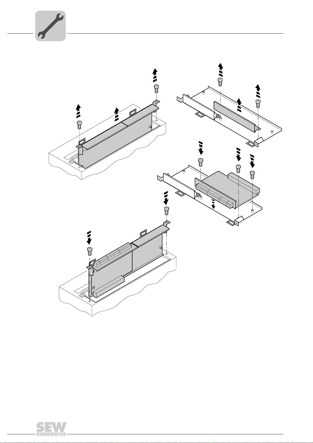
Figure 2: Installing an option card in MOVIDRIVE® MDX61B sizes 1 to 6
1. Remove the two retaining screws holding the card retaining bracket. Pull the card
retaining bracket out evenly from the slot (do not twist!).
2. Remove the 2 retaining screws from the black cover plate on the card retaining
bracket. Remove the black cover plate.
3. Position the option card onto the retaining bracket so that the 3 retaining screws fit
into the corresponding holes on the card retaining bracket.
4. Insert the retaining bracket with the installed option card into the slot, pressing
slightly so it is seated properly. Secure the card retaining bracket with the two retaining screws.
5. To remove the option card, follow the instructions in reverse order.
60039AXX
14
Manual – Fieldbus Interface DFE24B EtherCAT
Page 15
Assembly and Installation Notes
Installing option card DFE24B in MOVITRAC® B
4.2 Installing option card DFE24B in MOVITRAC® B
•MOVITRAC® B does not require any special firmware status.
• Only SEW-EURODRIVE personnel may install or remove options cards into
MOVITRAC
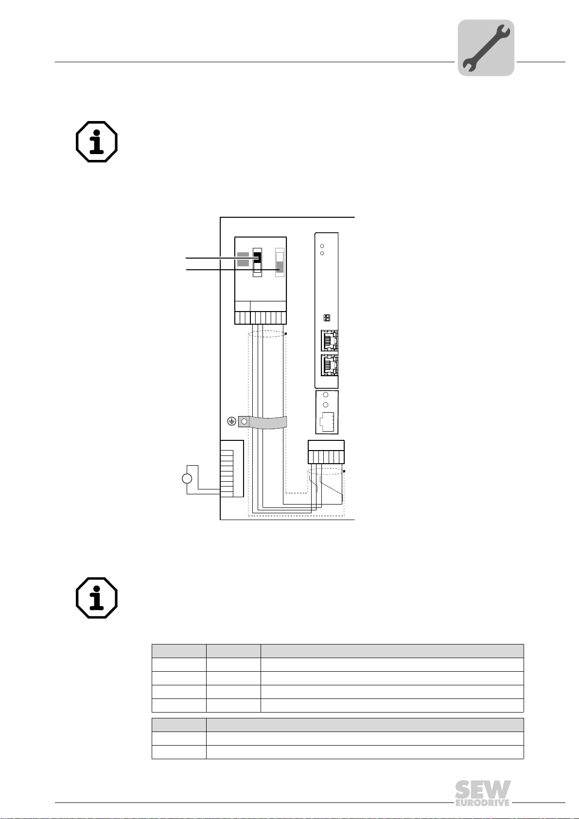
4.2.1 SBus connection
®
B.
4
DC 24 V
[1]
[2]
MOVITRAC® B
DFE 24B
RUN
ERR
X44
S1
S2
ON
OFF
FSC11B
X46
X45
7
23456HL ⊥
1
X12
1
2
3
+
=
24V IO
–
GND
4
5
6
7
8
9
01
AS
F1
EtherCAT
INX30OUTX31
OUTX31
H1
H2
X24
X26
1234567
[1] Terminating resistor activated, S1 = ON
[2] DIP switch S2 (reserved), S2 = OFF
• DFE24B has an integrated SBus terminating resistor and must always be installed at
the start of the SBus line.
• DFE24B always has the address 0.
X46 X26
X46:1 X26:1 SC11 SBus +, CAN high
X46:2 X26:2 SC12 SBus –, CAN low
X46:3 X26:3 GND, CAN GND
X46:7 X26:7 DC 24 V
X12
X12:8 DC 24 V input
X12:9 GND reference potential for binary inputs
Manual – Fieldbus Interface DFE24B EtherCAT
61212AXX
15
Page 16

4
Phone: 800.894.0412 - Fax: 888.723.4773 - Web: www.clrwtr.com - Email: info@clrwtr.com
Assembly and Installation Notes
Installing option card DFE24B in MOVITRAC® B
For simple cabling, the DFE24B option can be provided with DC 24 V voltage at X26.7
from X46.7 of MOVITRAC
When powering option DFE24B through MOVITRAC
provided with DC 24 V voltage at terminals X12.8 and X12.9.
4.2.2 System bus connection
S1
ON
OFF
X44
FSC11B
X46
X45
23456HL⊥
1
MOVITRAC® B
S2
7
DFE 24B
RUN
ERR
01
AS
F1
EtherCAT
INX30OUTX31
OUTX31
®
B.
®
B, MOVITRAC®B itself must be
X12
1
2
3
4
5
6
7
8
9
DC 24 V
+
=
-
24V IO
GND
Figure 3: System bus connection
DFE24B
GND = System bus reference
SC11 = System bus high
SC12 = System bus low
H1
H2
X24
X26
1234567
MOVITRAC® B
S1
S2
ON
OFF
X44
FSC11B
X46
X45
23456HL ⊥
1
7
MOVITRAC® B
GND = System bus reference
SC22 = System bus low, outgoing
SC21 = System bus high, outgoing
SC12 = System bus low, incoming
SC11 = System bus high, incoming
S12 = System bus terminating resistor
MOVITRAC® B
S1
ON
OFF
X44
FSC11B
X46
X45
23456HL ⊥
1
61073AXX
S2
7
16
Manual – Fieldbus Interface DFE24B EtherCAT
Page 17

Assembly and Installation Notes
Phone: 800.894.0412 - Fax: 888.723.4773 - Web: www.clrwtr.com - Email: info@clrwtr.com
Installing option card DFE24B in MOVITRAC® B
Please note:
• If available, use a 2 x 2 core twisted and shielded copper cable (data transmission
cable with braided copper shield). Apply the shield at both ends to the electronics
shield clamp of MOVITRAC
the shield ends additionally to GND. The cable must meet the following specifications:
– Core cross section 0.25 ... 0.75 mm
– Line resistance 120 Ω at 1 MHz
– Capacitance per unit length ≤ 40 pF/m at 1 kHz
Suitable would be CAN bus or DeviceNet cable.
• The permitted total cable length depends on the baud rate setting of the SBus:
– 250 kBaud: 160 m
– 500 kBaud: 80 m
– 1000 kBaud:40 m
• Connect the system bus terminating resistor (S1 = ON) at the end of the system bus
connection. Switch off the terminating resistor on the other units (S1 = OFF). The
DFE24B gateway has a permanently installed terminating resistor and must always
be located at the beginning or end of the system bus line.
• Star like bus structure is not permitted.
®
B over a large area. When using a 2-core cable connect
2
(AWG23 ... AWG18)
4
• There must not be any potential displacement between the units connected with the
SBus. Take suitable measures to avoid potential displacement, e.g. by connecting
the unit ground connectors using a separate lead.
Manual – Fieldbus Interface DFE24B EtherCAT
17
Page 18

4
V
Phone: 800.894.0412 - Fax: 888.723.4773 - Web: www.clrwtr.com - Email: info@clrwtr.com
Assembly and Installation Notes
Installing the UOH11B gateway housing
4.3 Installing the UOH11B gateway housing
SC11 Systembus +, CAN high
SC12 Systembus -, CAN low
GND, CAN GND
SEW Drive
UOH11B
DFE 24B
RUN
ERR
01
AS
F1
EtherCAT
INX30OUTX31
OUTX31
X24
X26
23456
1
H1
H2
7
DC+24
GND
X26
X26:1 SC11 System bus +, CAN high
X26:2 SC12 System bus -, CAN low
X26:3 GND, CAN GND
X26:6 GND, CAN GND
X26:7 DC 24 V
The gateway housing is powered with DC 24 V at X26.
61074AXX
18
Manual – Fieldbus Interface DFE24B EtherCAT
Page 19

Assembly and Installation Notes
Connection and terminal description of the DFE24B option
4.4 Connection and terminal description of the DFE24B option
Part number EtherCAT interface type DFE24B: 1821 126 7
4
The option "EtherCAT interface type DFE24B" is only possible in conjunction with
MOVIDRIVE
Plug the DFE24B option into the fieldbus slot.
Front view of DFE24B Description
DFE 24B
RUN: EtherCAT operation LED
RUN
ERR
01
AS
F1
(orange/green)
ERR: EtherCAT error LED (red)
DIP switch AS
®
MDX61B, not with MDX60B.
DIP
switches
Terminal
F1
Function
Shows the operating status of bus electronics and
communication.
Displays EtherCAT errors.
Auto setup for gateway operation
Reserved
EtherCAT
INX30OUTX31
OUTX31
Front view in
MOVITRAC
UOH11B
®
H1
H2
X24
58083AXX
B and
LED Link/Activity (green)
X30 IN: Incoming EtherCAT
connection
LED Link/Activity (green)
X31 OUT: Outgoing EtherCAT
connection
Description Function
LED H1 (red)
LED H2 (green)
X24 X terminal
Shows that the EtherCAT connection with the preceding unit is available/active.
Shows that the EtherCAT connection with the following unit is available/active.
System error (only for gateway functionality)
Reserved
RS485 interface for diagnostics via PC and
MOVITOOLS
®
MotionStudio
58129AXX
Manual – Fieldbus Interface DFE24B EtherCAT
19
Page 20
4
Phone: 800.894.0412 - Fax: 888.723.4773 - Web: www.clrwtr.com - Email: info@clrwtr.com
4.5 Pin assignment
Assembly and Installation Notes
Pin assignment
Use prefabricated, shielded RJ45 plug connectors to IEC11801 edition 2.0, category 5.
[1]
[2]
[3]
[6]
AB
Figure 4: Pin assignment of an RJ45 plug connector
A = Front view
B = View from back
[1] Pin 1 TX+ Transmit Plus
[2] Pin 2 TX– Transmit Minus
[3] Pin 3 RX+ Receive Plus
[6] Pin 6 RX– Receive Minus
6
3
2
1
54174AXX
DFE24B EtherCAT
connection
Option DFE24B is equipped with two RJ45 connectors for a linear bus structure. The
EtherCAT master is connected (if necessary, via additional EtherCAT slaves) to X30 IN
(RJ45) with a shielded, twisted-pair cable. Additional EtherCAT units are then
connected via X31 OUT (RJ45).
In accordance with IEC 802.3, the maximum permitted cable length for 100 MBaud
Ethernet (100BaseT), e.g. between two DFE24B units, is 100 m.
20
Manual – Fieldbus Interface DFE24B EtherCAT
Page 21

4.6 Shielding and routing bus cables
Phone: 800.894.0412 - Fax: 888.723.4773 - Web: www.clrwtr.com - Email: info@clrwtr.com
Only use shielded cables and connection elements that also meet the requirements of
category 5, class D according to IEC 11801 edition 2.0.
Correct shielding of the bus cable attenuates electrical interference that can occur in
industrial environments. The following measures ensure the best possible shielding:
• Manually tighten the mounting screws on the connectors, modules, and equipotential
bonding conductors.
• Use only connectors with a metal housing or a metallized housing.
• Connect the shielding in the connector over a wide surface area.
• Apply the shielding of the bus line on both ends.
• Route signal and bus cables in separate cable ducts. Do not route them parallel to
power cables (motor leads).
• Use metallic, grounded cable racks in industrial environments.
• Route the signal cable and the corresponding equipotential bonding close to each
other using the shortest possible route.
• Avoid using plug connectors to extend bus cables.
• Route the bus cables closely along existing grounding surfaces.
Assembly and Installation Notes
Shielding and routing bus cables
4
In case of fluctuations in the ground potential, a compensating current may flow via the
bilaterally connected shield that is also connected to the protective earth (PE). Make
sure you supply adequate equipotential bonding according in accordance with relevant
VDE regulations in such a case.
4.7 Bus termination
Bus termination (e.g. with bus terminating resistors) is not necessary. If no further device
is connected to an EtherCAT slave, it recognizes this automatically.
4.8 Setting the station address
EtherCAT devices from SEW-EURODRIVE do not have an address that can be set on
the unit. The units are detected by their position in the bus structure and are assigned
an address by the EtherCAT master. The addresses can be displayed, for example,
using the DBG60B keypad (parameter P093).
Manual – Fieldbus Interface DFE24B EtherCAT
21
Page 22

4
Phone: 800.894.0412 - Fax: 888.723.4773 - Web: www.clrwtr.com - Email: info@clrwtr.com
Assembly and Installation Notes
Operating displays of the DFE24B option
4.9 Operating displays of the DFE24B option
4.9.1 EtherCAT LEDs
There are two LEDs on the DFE24B EtherCAT option card that display the current status
of the DFE24B option and the EtherCAT system.
DFE24B
RUN
ERR
61070AXX
LED RUN
(green/orange)
The RUN LED (green/orange) signals the status of option DFE24B.
Status State Description
Off INIT Option DFE24B is in the state INIT.
Flashing
green
Lights up
once (green)
Green OPERATIONAL Option DFE24B is in the state OPERATIONAL.
Flickering
green
Flashing
orange
PRE-OPERATIONAL Option DFE24B is in the state PRE-OPERATIONAL.
SAFE-OPERATIONAL Option DFE24B is in the state SAFE-OPERATIONAL.
INITIALISATION or
BOOTSTRAP
NOT CONNECTED Option DFE24B has been switched on but has not yet been
• Option DFE24B is booting and has not yet reached the state
INIT.
• Option DFE24B is in the state BOOTSTRAP. The firmware
is being downloaded.
addressed by an EtherCAT master.
LED ERR (red) The ERR LED (red) signals an error on EtherCAT.
Status Error Description
Off No error EtherCAT communication of the DFE24B option is in the
Flickering Boot error A boot error has been detected. The state INIT was achieved,
Flashing Invalid configuration General configuration error.
Lights up
once
Lights up
twice
Lights up
three times
Lights up
four times
On PDI watchdog timeout A PDI watchdog timeout occurs.
Unrequested change
in status
Application watchdog
timeout
Reserved -
Reserved -
operating state.
but the "Change" parameter in the AL status register has been
set to "0x01:change/error".
The slave application has changed the EtherCAT state automatically. The "Change" parameter in the AL status register has
been set to "0x01:change/error".
A watchdog timeout occurred in the application.
22
Manual – Fieldbus Interface DFE24B EtherCAT
Page 23

Assembly and Installation Notes
Phone: 800.894.0412 - Fax: 888.723.4773 - Web: www.clrwtr.com - Email: info@clrwtr.com
Operating displays of the DFE24B option
Definition of the display statuses
Display Definition Time profile
On Display is always switched on.
Off Display is always switched off.
Flickering Display switches on and off at a
frequency of 10 Hz.
Lights up briefly
once
The display lights up briefly, followed
by on off phase.
Flashing Display switches on and off at a
frequency of 2.5 Hz (200 ms on,
200 ms off).
Lights up once The display lights up once (200 ms),
followed by a longer off phase
(1000 ms).
Lights up twice The display lights up twice in succes-
sion, followed by on off phase.
Lights up three
times
Lights up four
times
The display lights up three times in
succession, followed by on off phase.
The display lights up four times in
succession, followed by on off phase.
50ms
on
off
50ms
50ms
on
off
on
200ms 200ms
off
on
200ms 1s
off
on
200ms 1s
off
on
200ms
off
on
200ms
off
200ms 200ms
200ms 200ms
200ms 200ms
4
58094AXX
58095AXX
58096AXX
58097AXX
58100AXX
1s200ms 200ms
58101AXX
1s200ms 200ms 200ms 200ms
58102AXX
Manual – Fieldbus Interface DFE24B EtherCAT
23
Page 24

4
Phone: 800.894.0412 - Fax: 888.723.4773 - Web: www.clrwtr.com - Email: info@clrwtr.com
Assembly and Installation Notes
Operating displays of the DFE24B option
LED Link/Activity
(green)
4.9.2 Gateway LED
LEDs for the
gateway communication status
Each EtherCAT connection has a "Link/Activity" LED for the incoming EtherCAT cable
(X30) and the outgoing EtherCAT cable (X31). They signal whether the EtherCAT
connection to the preceding (X30) or following (X31) unit is available / active.
INX30OUTX31
LED"Link/Activity"
OUTX31
61195AXX
H1
H2
X24
58129axx
LED H1 Sys-Fault (red) Only for gateway function
Status State Description
Red System error Gateway not configured or one of the drives
Off SBus ok Gateway is configured correctly
Flashes Bus scan Bus is being checked by the gateway
is inactive
LED H2 (green) is reserved at present.
X terminal X24 is the RS485 interface for diagnostics via PC and MOVITOOLS
®
Motion-
Studio.
24
Manual – Fieldbus Interface DFE24B EtherCAT
Page 25
Validity of the XML files for DFE24B
Phone: 800.894.0412 - Fax: 888.723.4773 - Web: www.clrwtr.com - Email: info@clrwtr.com
5 Configuration and Startup
This section provides you with information on configuration for the EtherCAT master and
startup of the drive inverter for fieldbus operation.
The current version of the XML file for the DFE24B control card is available on the SEW
homepage under the heading "Software."
5.1 Validity of the XML files for DFE24B
Configuration and Startup
I
5
00
The XML file is needed when DFE24B is used as a fieldbus option in MOVIDRIVE® B
and as a gateway in MOVITRAC
Do not change or expand the entries in the XML file. SEW assumes no liability for
inverter malfunctions caused by a modified XML file!
®
B or a gateway housing (UOH11B).
5.2 Configuring the EtherCAT master for MOVIDRIVE® B with the XML file
5.2.1 XML for operation in MOVIDRIVE® B
An XML file (SEW_DFE24B.XML) is available for configuring the EtherCAT master.
Copy this file to a folder in the configuration software.
Refer to the manuals for the appropriate configuration software for details on this
procedure.
The XML files standardized by the EtherCAT Technology Group (ETG) can be read by
all EtherCAT masters.
Manual – Fieldbus Interface DFE24B EtherCAT
25
Page 26

I
Phone: 800.894.0412 - Fax: 888.723.4773 - Web: www.clrwtr.com - Email: info@clrwtr.com
5
Configuration and Startup
Configuring the EtherCAT master for MOVIDRIVE® B with the XML file
00
5.2.2 Configuration procedure
Proceed as follows to configure MOVIDRIVE
1. Install (copy) the XML file according to the specifications of your configuration software. Once the file has been installed correctly, the device appears next to the slave
stations (under SEW EURODRIVE → Drives) with the designation
MOVIDRIVE+DFE24B.
2. Use the [Insert] menu item to add the device to the EtherCAT structure. The address
is assigned automatically. You can give the device a name to make it easier to
identify.
3. Select the process data configuration required for your application (see section
5.2.3).
4. Connect the I/O or periphery data to the input and output data of the application
program.
Once configuration is complete, you can start EtherCAT communication. The LEDs
RUN and ERR indicate the communication status of option DFE24B (see section 4.9
"Operating displays of the DFE24B option").
®
B with EtherCAT fieldbus interface:
26
Manual – Fieldbus Interface DFE24B EtherCAT
Page 27

Configuration and Startup
Phone: 800.894.0412 - Fax: 888.723.4773 - Web: www.clrwtr.com - Email: info@clrwtr.com
Configuring the EtherCAT master for MOVIDRIVE® B with the XML file
I
5
00
5.2.3 PDO configuration for operation in MOVIDRIVE
In the CoE (CANopen over EtherCAT) variant, EtherCAT uses the process data objects
(PDO) defined in the CANopen standard for cyclical communication between master
and slave. CANopen Standard distinguishes between the process data objects Rx
(Receive) and Tx (Transmit).
Rx process data
objects
Tx process data
objects
Rx process data objects (Rx-PDO) are received by the EtherCAT slave. They transfer
process output data (control values, setpoints, digital output signals) from the EtherCAT
master to the EtherCAT slave.
Tx process data objects (TX-PDO) are returned from the EtherCAT slave to the
EtherCAT master. They transfer process input data (actual values, status, digital input
information, etc.).
In the DFE24B operating mode of MOVIDRIVE
for cyclical process input and output data.
• OutputData1 (Standard 10 PO)
Static PDO with 10 cyclical process output data words that are connected in fixed
configuration with the standard process data of MOVIDRIVE
Fieldbus Unit Profile" manual).
®
®
B, two different PDO types can be used
®
B (→ "MOVIDRIVE
®
• OutputData2 (Configurable PO)
Configurable PDO with up to 10 cyclical process output data words (16 Bit) and up
to 8 cyclical system variables (32 Bit) that can be configured as required and
connected to various process data of the drive inverter.
• InputData1 (Standard 10 PI)
Static PDO with 10 cyclical process input data words that are connected in fixed
configuration with the standard process data of MOVIDRIVE
Fieldbus Unit Profile" manual).
• InputData2 (Configurable PI)
Configurable PDO with up to 10 cyclical process input data words (16 Bit) and up to
8 cyclical system variables (32 Bit) that can be configured as required and connected
to various process data of the drive inverter.
®
B (→ "MOVIDRIVE
®
Manual – Fieldbus Interface DFE24B EtherCAT
27
Page 28

I
Phone: 800.894.0412 - Fax: 888.723.4773 - Web: www.clrwtr.com - Email: info@clrwtr.com
5
Configuration and Startup
Configuring the EtherCAT master for MOVIDRIVE® B with the XML file
00
List of the possible process data objects (PDO) for DFE24B MOVIDRIVE® B
Index Size Name Mapping Sync manager Sync unit
1600hex
(5632dec)
1602hex
(6656dec)
1A00hex
(5632dec)
1A02hex
(6658dec)
20 bytes OutputData1 (Standard 10 PDO) Fixed
2 ... 52 bytes OutputData2 (Configurable PO) - 2 0
20 bytes InputData1 (Standard 10 PI) Fixed
2 ... 52 bytes InputData2 (Configurable PI) - 3 0
content
20
30
content
Ethernet
Header
Frame
Header
EtherCAT
Header
Data ... FCS
Drive
EtherCAT
Master
acycl. Mailbox
Communication
EtherCAT
cycl. InputData1
(Standard 10 PI)
Figure 5: Use of the process data objects OutputData1 and InputData1
cycl. OutputData1
(Standard 10 PO)
acycl. Mailbox
Communication
SEW
Drive
61221AXX
28
Manual – Fieldbus Interface DFE24B EtherCAT
Page 29

Configuration and Startup
Phone: 800.894.0412 - Fax: 888.723.4773 - Web: www.clrwtr.com - Email: info@clrwtr.com
Configuring the EtherCAT master for MOVIDRIVE® B with the XML file
Static PDO for 10
cyclic process
data words
PO 1 PO 2 PO 3 PO 4 PO 5 PO 6 PO 7 PO 8 PO 9 PO 10
acycl. Mailbox
Communication
cycl. OutputData1
(Standard 10 PO)
I
5
00
Fixed assignments of the configured process
output data for
PDO OutputData1
MOVIDRIVE
Proces s D at a 1...3 or
®
plus
IPOS
®
Process Data 1...3
IPOS
MOVIDRIVE
®
plus
Proces s D at a 4...10
®
61223AXX
Figure 6: Assignment of standard process output data for OutputData1
The process output data transferred with OutputData1 are assigned according to the following table. The process output data PO1 ... PO3 can be connected with various
process data (control words, setpoints) using the process data configuration in the
MOVIDRIVE
process output data PO4 ... PO10 are only available in IPOS
Index.Subindex Offset in PDO Name Data type Size in bytes
3DB8.0hex
(15800.0dec)
3DB9.0hex
(15801.0dec)
3DBA.0hex
(15802.0dec)
3DBB.0hex
(15803.0dec)
3DBC.0hex
(15804.0dec)
3DBD.0hex
(15805.0dec)
3DBE.0hex
(15806.0dec)
3DBF.0hex
(15807.0dec)
3DC0.0hex
(15808.0dec)
3DC1.0hex
(15809.0dec)
®
B drive inverter (→ "MOVIDRIVE® Fieldbus Unit Profile" manual). The
0.0 PO1 UINT
2.0 PO2 UINT
4.0 PO3 UINT
6.0 PO4 UINT
8.0 PO5 UINT
10.0 PO6 UINT
12.0 PO7 UINT
14.0 PO8 UINT
16.0 PO9 UINT
18.0 PO10 UINT
plus®
.
2
Manual – Fieldbus Interface DFE24B EtherCAT
29
Page 30

5
Phone: 800.894.0412 - Fax: 888.723.4773 - Web: www.clrwtr.com - Email: info@clrwtr.com
Fixed assignment
of the configured
process input data
for PDO
InputData1
I
Configuration and Startup
Configuring the EtherCAT master for MOVIDRIVE® B with the XML file
00
MOVIDRIVE
Proces s D at a 1...3 or
®
plus
IPOS
PI 1 PI 2 PI 3 PI 4 PI 5 PI 6 PI 7 PI 8 PI 9 PI 10
®
Process Data 1...3
IPOS
MOVIDRIVE
®
plus
Proces s D at a 4...10
®
cycl. InputData1
(Standard 10 PI)
acycl. Mailbox
Communication
61226AXX
Figure 7: Assignment of the standard process input data for PDO InputData1
The process input data transferred with InputData1 are assigned according to the
following table. The process input data PI1 ... PI3 can be connected with various process
data (status words, actual values) using the process data configuration in the
MOVIDRIVE
process input data PI4 ... PI10 are only available in IPOS
Index.Subindex Offset in PDO Name Data type Size in bytes
3E1C.0hex
(15900.0dec)
3E1D.0hex
(15901.0dec)
3E1E.0hex
(15902.0dec)
3E1F.0hex
(15903.0dec)
3E20.0hex
(15904.0dec)
3E21.0hex
(15905.0dec)
3E22.0hex
(15906.0dec)
3E23.0hex
(15907.0dec)
3E24.0hex
(15908.0dec)
3E25.0hex
(15909.0dec)
®
B drive inverter (→ "MOVIDRIVE® Fieldbus Unit Profile" manual). The
0.0 PI1 UINT
2.0 PI2 UINT
4.0 PI3 UINT
6.0 PI4 UINT
8.0 PI5 UINT
10.0 PI6 UINT
12.0 PI7 UINT
14.0 PI8 UINT
16.0 PI9 UINT
18.0 PI10 UINT
plus®
.
2
If fewer than 10 process data words are to be transferred, or if the PDO mapping is to
be adjusted, the configurable PDOs are to be used instead of the static PDO.
30
Manual – Fieldbus Interface DFE24B EtherCAT
Page 31

Configuration and Startup
Phone: 800.894.0412 - Fax: 888.723.4773 - Web: www.clrwtr.com - Email: info@clrwtr.com
Configuring the EtherCAT master for MOVIDRIVE® B with the XML file
I
5
00
Configurable PDO
for up to 8 IPOS-
plus®
variables and
10 process data
words
The process data transferred with OutputData2 and InputData2 can be configured as required with process data information according to the following table. 32-bit variables of
type DINT and standard process data PO1 ... PO10 and PI1 ... PI10 can be configured.
In this way, the PDO can be configured to suit any application.
Ethernet
Header
EtherCAT
Figure 8: Use of the configurable PDO OutputData2, InputData2
Frame
Header
Master
EtherCAT
EtherCAT
Header
Data
acycl. Mailbox
Communication
cycl. InputData2
(Configurable PI)
Drive
cycl. OutputData2
(Configurable PO)
acycl. Mailbox
Communication
SEW
Drive
...
61230AXX
FCS
acycl. Mailbox
Communication
PO1 PO2 PO106. Variable 7. Variable
1. Variable
max. 10 Process Data
PO1..10 (UINT)
cycl. OutputData2
(Configurable PO)
max. 8 IPOS
Variables (D INT)
plus
®
Figure 9: Configurable PDO mapping for OutputData2
max. 10 Process Data
PI1..10 (UINT)
PI1 PI102. Variable 8. Variable1. Variable 7. Variable
max. 8 IPOS
Variables (D INT)
cycl. InputData2
(Configurable PI)
plus
acycl. Mailbox
Communication
8. Variable
61232AXX
®
Figure 10: Configurable PDO mapping for InputData2
Manual – Fieldbus Interface DFE24B EtherCAT
61237AXX
31
Page 32

5
Phone: 800.894.0412 - Fax: 888.723.4773 - Web: www.clrwtr.com - Email: info@clrwtr.com
I
Configuration and Startup
Configuring the EtherCAT master for MOVIDRIVE® B with the XML file
00
Assignment of the
configurable
process input and
output data for
PDO OutputData2
and InputData2
The maximum amount of configurable PDO OutputData2 and InputData2 data is
• 10 process data words (type UINT)
plus®
• 8 IPOS
Index.Subindex Name Data
2AF8.0hex
(11000.0dec)
2CBD.0hex
(11453.0dec)
2CBE.0hex
(11454.0dec)
2CBF.0hex
(11455.0dec)
2CC0.0hex
(11456.0dec)
2CD1.0hex
(11473.0dec)
2CD2.0hex
(11474dec)
2CD3.0hex
(11475.0dec)
2CD6.0hex
(11478.0dec)
2CD7.0hex
(11478.0dec)
2CD8.0hex
(11480.0dec)
2CD9.0hex
(11481.0dec)
2CDA.0hex
(11482.0dec)
2CDB.0hex
(11483.0dec)
2CDC.0hex
(11484.0dec)
2CE4.0hex
(11492.0dec)
2CE7.0hex
(11495.0dec)
2CEB.0hex
(11499.0dec)
2CEC.0hex
(11500.0dec)
2CED.0hex
(11501.0dec)
2CEE.0hex
(11502.0dec)
2CEF.0hex
(11503dec)
variables (type DINT)
Size in
type
Template IposVar (0...1023)
ModuloCtrl
(H453)
ModTagPos
(H454)
ModActPos
(H455)
ModCount
(H456)
StatusWord
(H473)
Scope474 Direct Scope variable
Scope475
H475)
AnaOutIPOS2
(H478)
AnaOutIPOS
(H479)
OptOutIPOS
(H480)
StdOutIPOS
(H481)
OutputLevel
(H482)
InputLevel
(H483)
ControlWord
(H484)
TargetPos
(H492)
LagDistance
(H495)
SetpPosBus
(H499)
TpPos2_VE
(H500)
TpPos1_VE
(H501)
TpPos2_Abs
(H502)
TpPos1_Abs
(H503)
DINT 4 4
bytes
Read
Write
Access attribute
Template for IPOS
Control word of the Modulo function
Modulo target position
Modulo actual position
Modulo counter value
IPOS status word
Direct Scope variable
Analog output 2 option DIO11B
Analog output option DIO11B
Optional digital outputs
Standard digital outputs
Status of the digital outputs
Status of the digital inputs
®
IPOSplus
Target position
Lag distance
Bus position setpoint
Touch probe position 2 virtual
encoder
Touch probe position 1 virtual
encoder
Touch probe position 2
Touch probe position 1
control word
plus®
variables
32
Manual – Fieldbus Interface DFE24B EtherCAT
Page 33

Configuration and Startup
Phone: 800.894.0412 - Fax: 888.723.4773 - Web: www.clrwtr.com - Email: info@clrwtr.com
Configuring the EtherCAT master for MOVIDRIVE® B with the XML file
I
5
00
Index.Subindex Name Data
2CF0.0hex
(11504.0dec)
2CF1.0hex
(11505.0dec)
2CF2.0hex
(11506.0dec)
2CF3.ohex
(11507.0dec)
2CF4.0hex
(11508.0dec)
2CF5.0hex
(11509dec)
2CF6.0hex
(11510.0dec)
2CF7.0hex
(11511.0dec)
3DB8.0hex
(15800.0dec)
3DB9.0hex
(15801.0dec)
3DBA.0hex
(15802.0dec)
3DBB.0hex
(15803.0dec)
3DBC.0hex
(15804.0dec)
3DBD.0hex
(15805.0dec)
3DBE.0hex
(15806.0dec)
3DBF.0hex
(15807.0dec)
3DC0.0hex
(15808.0dec)
3DC1.0hex
(15801.0dec)
3E1C.0hex
(15900.0dec)
3E1D.0hex
(1590010dec)
3E1E.0hex
(15902.0dec)
3E1F.0hex
(15903.0dec)
3E20.0hex
904.0dec)
(15
3E21.0hex
(15905.0dec)
3E22.0hex
(15906.0dec)
3E23.0hex
(15907.0dec)
3E24.0hex
(15908.0dec)
3E25.0hex
(15909.0dec)
TpPos2_Ext
(H504)
TpPos2_Mot
(H505)
TpPos1_Ext
(H506)
TpPos1_Mot
(H507)
ActPos_Mot16
bit (H508)
ActPos_Abs
(H509)
ActPos_Ext
(H510)
ActPos_Mot
(H511)
PO1
PO2 Standard process output data word
PO3 Standard process output data word
PO4 Standard process output data word
PO5 Standard process output data word
PO6 Standard process output data word
PO7 Standard process output data word
PO8 Standard process output data word
PO9 Standard process output data word
PO10 Standard process output data word
PI1 Standard process input data word
PI2 Standard process input data word
PI3 Standard process input data word
PI4 Standard process input data word
PI5 Standard process input data word
PI6 St
PI7 Standard process input data word
PI8 Standard process input data word
PI9 Standard process input data word
PI10 Standard process input data word
type
DINT 4 4
UINT 2 2
Size in
bytes
Read
Write
Access attribute
Touch probe position 2 external
Touch probe position 2 motor
encoder
Touch probe position 1 external
Touch probe position 1 motor
Actual position motor 16 Bit
Actual position absolute encoder
Actual position external encoder
X14
Actual position motor encoder
Standard process output data word
PO1
PO2
PO3
PO4
PO5
PA6
PO7
PO8
PO9
PO10
PI1
PI2
PI3
PI4
PI5
andard process input data word
PI6
PI7
PI8
PI9
PI10
Manual – Fieldbus Interface DFE24B EtherCAT
33
Page 34

5
Phone: 800.894.0412 - Fax: 888.723.4773 - Web: www.clrwtr.com - Email: info@clrwtr.com
I
Configuration and Startup
Configuring the EtherCAT master for MOVIDRIVE® B with the XML file
00
Plausibility of the configuration of process data objects:
• In the freely configurable process data objects OutputData2 and InputData2, cyclical
process output data PO1 ... 10 cannot be inserted when OutputData1 or InputData1
is configured at the same time.
• Multiple configuration of process data objects is not possible.
• Only standard process data objects PO1 ... PO10, PI1 ... PI10 or IPOS
(indices 11000.0 ... 12023.0) can be configured as process data.
plus®
variables
34
Manual – Fieldbus Interface DFE24B EtherCAT
Page 35

Configuration and Startup
Phone: 800.894.0412 - Fax: 888.723.4773 - Web: www.clrwtr.com - Email: info@clrwtr.com
Configuring the EtherCAT master for MOVITRAC® B / gateway with XML file
00
5.3 Configuring the EtherCAT master for MOVITRAC® B / gateway with XML file
This section describes the configuration of the EtherCAT master with MOVITRAC® B
and the DFE24B gateway / UOH11B.
I
5
5.3.1 XML files for operation in MOVITRAC
An XML file (SEW_DFE24B.XML) is available for configuring the EtherCAT master.
Copy this file to a folder in the configuration software.
Refer to the manuals for the appropriate configuration software for details on this
procedure.
The XML files standardized by the EtherCAT Technology Group (ETG) can be read by
all EtherCAT masters.
5.3.2 Configuration procedure
Proceed as follows to configure MOVITRAC
1. Install (copy) the XML file according to the specifications of your configuration software. Once the file has been installed correctly, the device appears next to the slave
stations (under SEW EURODRIVE → Drives) with the designation DFE24B-
Gateway.
2. Use the [Insert] menu item to add the device to the EtherCAT structure. The address
is assigned automatically. You can give the device a name to make it easier to
identify.
3. Connect the I/O or periphery data to the input and output data of the application
program.
®
B and gateway housing UOH11B
®
/ gateways with the EtherCAT interface:
Once configuration is complete, you can start EtherCAT communication. The LEDs
RUN and ERR indicate the communication status of option DFE24B (see section 4.9
"Operating displays of the DFE24B option").
Manual – Fieldbus Interface DFE24B EtherCAT
35
Page 36

EURODRIVE
EURODRIVE
EURODRIVE
EURODRIVE
EURODRIVE
EURODRIVE
EURODRIVE
EURODRIVE
I
Phone: 800.894.0412 - Fax: 888.723.4773 - Web: www.clrwtr.com - Email: info@clrwtr.com
5
Configuration and Startup
Configuring the EtherCAT master for MOVITRAC® B / gateway with XML file
00
5.3.3 PDO configuration for DFE24B gateway for MOVITRAC® B
In the DFE24B gateway operating mode for MOVITRAC
®
B, one PDO each is used for
cyclical process input and output data.
• OutputData1 (Standard 24 PO)
Static PDO with 24 cyclical process output data words that are connected in fixed
configuration with the process data of a maximum of 8 MOVITRAC
®
B connected to
the gateway.
• InputData1 (Standard 24 PI)
Static PDO with 24 cyclical process input data words that are connected in fixed
configuration with the process data of a maximum of 8 MOVITRAC
®
B connected to
the gateway.
List of the possible PDO for the DFE24B gateway:
Index Size Name Mapping Sync manager Sync unit
1601hex
(5633dec)
1A01hex
(5633dec)
48 bytes OutputData1 (Standard 24 PO) Fixed
content
48 bytes InputData1 (Standard 24 PI) Fixed
content
20
30
Ethernet
Header
EtherCAT
Master
EtherCAT
Frame
Header
EtherCAT
Header
Data
acycl. Mailbox
Communication
cycl. InputData1
(Standard 24 PI)
Unit = SBus-Address: 1 2 3 4 5 6 7 8
Drive
cycl. OutputData1
(Standard 24 PO)
acycl. Mailbox
Communication
B
®
EURODRIVEEURODRIVE
MOVITRAC
EURODRIVEEURODRIVE
EURODRIVEEURODRIVE
EURODRIVEEURODRIVE
DFE 24B
AS
F1
EtherCAT
INX30OUTX31
OUTX31
... FCS
RUN
ERR
01
EURODRIVEEURODRIVE
EURODRIVEEURODRIVE
EURODRIVEEURODRIVE
EURODRIVEEURODRIVE
Figure 11: Data exchange (PDO OutputData1, InputData1) with EtherCAT master
36
Manual – Fieldbus Interface DFE24B EtherCAT
61242AXX
Page 37

Configuration and Startup
Phone: 800.894.0412 - Fax: 888.723.4773 - Web: www.clrwtr.com - Email: info@clrwtr.com
Configuring the EtherCAT master for MOVITRAC® B / gateway with XML file
Assignment of the fixed configured process output data (PDO 1)
I
5
00
acycl. Mailbox
Communication
PO1 PO2 PO3 PO4 PO5 PO6 PO22 PO23 PO24
Dr i ve 1
PO1...PO3
cycl. OutputData1
(Standard 10 PO)
Dr i ve 2
PO1...PO3
Dr i ve 8
PO1...PO3
61239AXX
Figure 12: Assignment of standard process output data for OutputData1
The process output data transferred with OutputData1 are assigned according to the following table. For each inverter, the process output data PO1 ... PO3 can be connected
with various process data (control words, setpoints) using the process data configuration in the MOVITRAC
Index.Subindex Offset in PDO Name Assignment Data type Size in bytes
3DB8.0hex
(15800.0dec)
3DB9.0hex
(15801.0dec)
3DBA.0hex
(15802.0dec)
3DBB.0hex
(15803.0dec)
3DBC.0hex
(15804.0dec)
3DBD.0hex
(15805.0dec)
3DBE.0hex
(15806.0dec)
3DBF.0hex
(15807.0dec)
3DC0.0hex
(15808.0dec)
3DC1.0hex
(15809.0dec)
3DC2.0hex
(15810.0dec)
3DC3.0hex
(15811.0dec)
3DC4.0hex
(15812.0dec)
3DC5.0hex
(15813.0dec)
3DC6.0hex
(15814.0dec)
®
B drive inverter (→ "MOVITRAC® B" operating instructions).
0.0 PO1 Drive 1 PO1
2.0 PO2 Drive 1 PO2
4.0 PO3 Drive 1 PO3
6.0 PO4 Drive 2 PO1
8.0 PO5 Drive 2 PO2
10.0 PO6 Drive 2 PO3
12.0 PO7 Drive 3 PO1
14.0 PO8 Drive 3 PO2
16.0 PO9 Drive 3 PO3
18.0 PO10 Drive 4 PO1
0.0 PO11 Drive 4 PO2
2.0 PO12 Drive 4 PO3
4.0 PO13 Drive 5 PO1
6.0 PO14 Drive 5 PO2
8.0 PO15 Drive 5 PO3
UINT 2
Manual – Fieldbus Interface DFE24B EtherCAT
37
Page 38

5
Phone: 800.894.0412 - Fax: 888.723.4773 - Web: www.clrwtr.com - Email: info@clrwtr.com
I
Configuration and Startup
Configuring the EtherCAT master for MOVITRAC® B / gateway with XML file
00
Index.Subindex Offset in PDO Name Assignment Data type Size in bytes
3DC7.0hex
(15815.0dec)
3DC8.0hex
(15816.0dec)
3DC9.0hex
(15817.0dec)
3DCA.0hex
(15818.0dec)
3DCB.0hex
(15819.0dec)
3DCC.0hex
(15820.0dec)
3DCD.0hex
(15821.0dec)
3DCE.0hex
(15822.0dec)
3DCF.0hex
(15823.0dec)
10.0 PO16 Drive 6 PO1
12.0 PO17 Drive 6 PO2
14.0 PO18 Drive 6 PO3
16.0 PO19 Drive 7 PO1
18.0 PO20 Drive 7 PO2
18.0 PO21 Drive 7 PO3
18.0 PO22 Drive 8 PO1
18.0 PO23 Drive 8 PO2
18.0 PO24 Drive 8 PO3
UINT 2
38
Manual – Fieldbus Interface DFE24B EtherCAT
Page 39

Configuration and Startup
Phone: 800.894.0412 - Fax: 888.723.4773 - Web: www.clrwtr.com - Email: info@clrwtr.com
Configuring the EtherCAT master for MOVITRAC® B / gateway with XML file
Assignment of the fixed configured process input data (PDO 1)
I
5
00
Drive 1
PI1...PI3
PI1 PI2 PI3 PI4 PI5 PI6 PI22 PI23 PI24
Dr i ve 2
PI1...PI3
cycl. InputData1
(Standard 10 PI)
Drive 8
PI1...PI3
acycl. Mailbox
Communication
61240AXX
Figure 13: Assignment of the standard process input data for InputData1
The process input data transferred with InputData1 are assigned according to the
following table. The process input data PI1 ... PI3 can be connected with various process
data (status words, actual values) using the process data configuration in the
MOVITRAC
Index.Subindex Offset in PDO Name Assignment Data type Size in bytes
3E1C.0hex
(15900.0dec)
3E1D.0hex
(15901.0dec)
3E1E.0hex
(15902.0dec)
3E1F.0hex
(15903.0dec)
3E20.0hex
(15904.0dec)
3E21.0hex
(15905.0dec)
3E22.0hex
(15906.0dec)
3E23.0hex
(15907.0dec)
3E24.0hex
(15908.0dec)
3E25.0hex
(15909.0dec)
3E26.0hex
(15910.0dec)
3E27.0hex
(15911.0dec)
3E28.0hex
(15912.0dec)
3E29.0hex
(15913.0dec)
3E2A.0hex
(15914.0dec)
®
B drive inverter (→ "MOVITRAC® B" operating instructions).
0.0 PI1 Drive 1 PI1
2.0 PI2 Drive 1 PI2
4.0 PI3 Drive 1 PI3
6.0 PI4 Drive 2 PI1
8.0 PI5 Drive 2 PI2
10.0 PI6 Drive 2 PI3
12.0 PI7 Drive 3 PI1
14.0 PI8 Drive 3 PI2
16.0 PI9 Drive 3 PI3
18.0 PI10 Drive 4 PI1
20.0 PI11 Drive 4 PI2
22.0 PI12 Drive 4 PI3
24.0 PI13 Drive 5 PI1
26.0 PI14 Drive 5 PI2
28.0 PI15 Drive 5 PI3
UINT 2
Manual – Fieldbus Interface DFE24B EtherCAT
39
Page 40

5
Phone: 800.894.0412 - Fax: 888.723.4773 - Web: www.clrwtr.com - Email: info@clrwtr.com
I
Configuration and Startup
Configuring the EtherCAT master for MOVITRAC® B / gateway with XML file
00
Index.Subindex Offset in PDO Name Assignment Data type Size in bytes
3E2B.0hex
(15915.0dec)
3E2C.0hex
(15916.0dec)
3E2D.0hex
(15917.0dec)
3E2E.0hex
(15918.0dec)
3E2F.0hex
(15919.0dec)
3E30.0hex
(15920.0dec)
3E31.0hex
(15921.0dec)
3E32.0hex
(15922.0dec)
3E33.0hex
(15923.0dec)
30.0 PI16 Drive 6 PI1 UINT 2
32.0 PI17 Drive 6 PI2
34.0 PI18 Drive 6 PI3
36.0 PI19 Drive 7 PI1
38.0 PI20 Drive 7 PI2
40.0 PI21 Drive 7 PI3
42.0 PI22 Drive 8 PI1
44.0 PI23 Drive 8 PI2
46.0 PI24 Drive 8 PI3
40
Manual – Fieldbus Interface DFE24B EtherCAT
Page 41

Configuration and Startup
Phone: 800.894.0412 - Fax: 888.723.4773 - Web: www.clrwtr.com - Email: info@clrwtr.com
Configuring the EtherCAT master for MOVITRAC® B / gateway with XML file
5.3.4 Auto setup for gateway operation
The auto setup function can be used to startup DFE24B as a gateway without a PC. The
function is activated using the DIP switch Auto-Setup (see section 4.4 on page 19) .
Setting the DIP switch Auto-Setup (AS) from OFF to ON position causes the function to
be executed once. The Auto-Setup DIP switch must then remain in ON position.
The function can be reactivated by turning the DIP switch off and back on again.
First, the DFE24B searches on the lower-level SBus for SEW drives. This process is indicated by the LED H1 (system error) flashing briefly. For this purpose, different SBus
addresses must be set for the drive inverters (P881). We recommend assigning the
addresses beginning with address 1 in ascending order based on the arrangement of
inverters in the control cabinet. The process image on the fieldbus side is expanded by
three words for each detected drive inverter.
The LED H1 remains lit if no drive inverter is located. A total of up to 8 drive inverters is
taken into account.
After the search is completed, the DFE24B cyclically exchanges 3 process data words
with each connected drive inverter. The process output data is taken from the fieldbus,
divided into blocks of three and transmitted. The drive inverters read the process input
data, put it together and send it to the fieldbus master.
The cycle time of SBus communication is 2 ms per station.
For an application with 8 inverters on the SBus, the cycle time for the process data
update will be 8 x 2 ms = 16 ms.
I
5
00
If you change the process data assignment of the drive inverters connected to DFE24B,
you must activate Auto-Setup again because the DFE24B saves these values only once
during Auto-Setup. At the same time, the process data assignments of the connected
drive inverters may not be changed dynamically after Auto-Setup.
Manual – Fieldbus Interface DFE24B EtherCAT
41
Page 42

I
Phone: 800.894.0412 - Fax: 888.723.4773 - Web: www.clrwtr.com - Email: info@clrwtr.com
5
Configuration and Startup
Setting the MOVIDRIVE® MDX61B drive inverter
00
5.4 Setting the MOVIDRIVE® MDX61B drive inverter
The following settings must be made for simple fieldbus operation.
11638AXX
®
However, to control the MOVIDRIVE
switch the drive inverter to control signal source (P101) and setpoint source (P100) =
FIELDBUS. The FIELDBUS setting means the drive inverter parameters are set for
control and setpoint entry via EtherCAT. The MOVIDRIVE
responds to the process output data transmitted from the PLC.
The parameters of the MOVIDRIVE
CAT without any further settings once the EtherCAT option card has been installed. For
example, all parameters can be set by the master programmable controller after poweron.
B drive inverter via EtherCAT, you must first
®
B drive inverter now
®
B drive inverter can be set straight away via Ether-
42
Manual – Fieldbus Interface DFE24B EtherCAT
Page 43

Configuration and Startup
Phone: 800.894.0412 - Fax: 888.723.4773 - Web: www.clrwtr.com - Email: info@clrwtr.com
Setting the MOVITRAC® frequency inverter
Activation of the control signal source and setpoint source FIELDBUS is signaled to the
machine controller using the "Fieldbus mode active" bit in the status word.
For safety reasons, you must also enable the MOVIDRIVE
terminals for control via the fieldbus system. Consequently, you must wire and program
the terminals in such a way that the inverter is enabled via the input terminals. The
simplest way of enabling the inverter on the terminal side is to set the DIØØ input
terminal (Function /CONTROLLER INHIBIT) to a +24 V signal and to program the input
terminals DIØ1 ... DIØ7 to NO FUNCTION.
The whole procedure for starting up the MOVIDRIVE
connection is described in sections 6 and 7.
5.5 Setting the MOVITRAC® frequency inverter
I
00
®
B drive inverter at the
®
B drive inverter with EtherCAT
5
Manual – Fieldbus Interface DFE24B EtherCAT
11639AXX
43
Page 44

5
Phone: 800.894.0412 - Fax: 888.723.4773 - Web: www.clrwtr.com - Email: info@clrwtr.com
I
Configuration and Startup
Setting the MOVITRAC® frequency inverter
00
To control the MOVITRAC® B frequency inverter via EtherCAT, you must first switch the
inverter to Control signal source (P101) and Setpoint source (P100) = SBus. The SBus
setting means the MOVITRAC
transfer from the gateway. The MOVITRAC
process output data transmitted from the PLC.
To ensure that the MOVITRAC
is interrupted, set the SBus1 timeout time (P883) to a value other than 0 ms. We
recommend a value between 50 and 200 ms.
Activation of the control signal source and setpoint source SBus is signaled to the
machine controller using the "SBus mode active" bit in the status word.
For safety reasons, you must also enable the frequency inverter at the terminals for
control via the fieldbus system. Consequently, you must wire and program the terminals
in such a way that the inverter is enabled via the input terminals. The simplest way of
enabling the frequency inverter on the terminal side is to set the DIØØ input terminal
(function CW/STOP) to a +24 V signal and to program the other input terminals to NO
FUNCTION.
®
B frequency inverter parameters are set for setpoint
®
B frequency inverter stops when SBus communication
®
B frequency inverter now responds to the
Configure the parameter P881 SBus address to values 1 ... 8 in ascending order.
SBus address 0 is used by the DFE24B gateway, and so cannot be used here.
Configure the parameter P883 SBus timeout to values 50 ... 200 ms.
44
Manual – Fieldbus Interface DFE24B EtherCAT
Page 45

EtherCAT Operating Characteristics
Phone: 800.894.0412 - Fax: 888.723.4773 - Web: www.clrwtr.com - Email: info@clrwtr.com
Controlling the MOVIDRIVE® MDX61B drive inverter
6 EtherCAT Operating Characteristics
This section describes the basic characteristics of the drive inverter on EtherCAT with
control via fixed PDO for fieldbus communication (motion control applications → Sec. 7).
6.1 Controlling the MOVIDRIVE® MDX61B drive inverter
The MOVIDRIVE® B drive inverter is controlled using the fixed PDO, which are 10 I/O
words long. These process data words are mapped directly in the process image when
using an EtherCAT master, which means they can be addressed directly by the control
program.
I
6
00
EtherCAT
Master
Ethernet
Header
Frame
Header
EtherCAT
Header
SEW
Drive
Data ...
SEW
Drive
Drive 1
SEW
Drive
Drive 2 Drive 3
I/O
FCS
EtherCAT
Figure 14: EtherCAT with SEW Drives
For more information on controlling via the process data channel, in particular the coding
of the control and status words, refer to the "Fieldbus Unit Profile" manual.
61375AXX
Manual – Fieldbus Interface DFE24B EtherCAT
45
Page 46

I
Phone: 800.894.0412 - Fax: 888.723.4773 - Web: www.clrwtr.com - Email: info@clrwtr.com
6
EtherCAT Operating Characteristics
Controlling the MOVIDRIVE® MDX61B drive inverter
00
6.1.1 Control example in TwinCAT with MOVIDRIVE® MDX61B
Once the SEW_DFE24B.xml file has been copied to the TwinCAT subdirectory
"\IO\EtherCAT", you can use the function "Append box" to insert a MOVIDRIVE
in the EtherCAT structure (→ following figure).
®
B unit
11641AXX
In "online mode" (i.e. when connected with the EtherCAT line), you can use the symbol
"Find devices" to search the EtherCAT line for connected MOVIDRIVE
following figure).
For simple fieldbus functionality, NC axes do not necessarily have to be created for each
device that is found.
®
units (→
11642AXX
46
Manual – Fieldbus Interface DFE24B EtherCAT
Page 47

EtherCAT Operating Characteristics
Phone: 800.894.0412 - Fax: 888.723.4773 - Web: www.clrwtr.com - Email: info@clrwtr.com
I
Controlling the MOVIDRIVE® MDX61B drive inverter
00
For the simplest form of process data transport, only the two PDOs InputData1 and
OutputData1 are required. You can deactivate the configurable PDOs by deleting the
marker for both PDOs (Input and Output) (→ following figure).
6
11643AXX
Manual – Fieldbus Interface DFE24B EtherCAT
47
Page 48

6
Phone: 800.894.0412 - Fax: 888.723.4773 - Web: www.clrwtr.com - Email: info@clrwtr.com
I
EtherCAT Operating Characteristics
Controlling the MOVIDRIVE® MDX61B drive inverter
00
Now, you can either connect up to 10 process data words with the PLC program or - as
shown in the following figure - write them for manual testing.
First select process output data PO1. In the window that appears, choose the tab page
"Online". Click "Write". The "Set Value Dialog" window opens. Enter your data in the
"Dec" or "Hex" field. Repeat the procedure for process output data PO2.
The 10 process input and output data words are assigned and scaled in MOVIDRIVE
in the 87_ parameter group or defined via an IPOS
For more information, refer to the "MOVIDRIVE
"Fieldbus Unit Profile" manual.
6.1.2 EtherCAT timeout (MOVI DRI VE
If data transfer via EtherCAT is disturbed or interrupted, the fieldbus monitoring time
(standard value 100 ms) configured in the master elapses in MOVIDRIVE
The DFE24B ERR LED signals that no new user data can be received. At the same
time, MOVIDRIVE
timeout response.
P819 Fieldbus timeout displays the monitoring time specified by the master during the
EtherCAT startup. The duration of the timeout can only be changed via the master. Modifications made using the keypad or MOVITOOLS
written during the next startup of the PLC.
11644AXX
plus®
program or application module.
®
MDX60B/61B" system manual and the
®
MDX61B)
®
MDX61B.
®
MDX61B performs the fault response selected with P831 Fieldbus
®
do not have any effect and are over-
®
B
6.1.3 Fieldbus timeout response (MOVIDRIVE
®
MDX61B)
Parameter P831 Fieldbus timeout delay is used to set the fault response that is triggered
via the fieldbus timeout monitoring function. The setting made here must match the configuration of the master system.
48
Manual – Fieldbus Interface DFE24B EtherCAT
Page 49

EtherCAT Operating Characteristics
EURODRIVE
EURODRIVE
EURODRIVE
EURODRIVE
EURODRIVE
EURODRIVE
EURODRIVE
EURODRIVE
Phone: 800.894.0412 - Fax: 888.723.4773 - Web: www.clrwtr.com - Email: info@clrwtr.com
Controlling the MOVITRAC® B (Gateway) frequency inverter
6.2 Controlling the MOVITRAC® B (Gateway) frequency inverter
The frequency inverters connected to the gateway are controlled via the process data
channel, which is 3 I/O data words for each connected inverter. These process data
words are mapped directly in the process image when using an EtherCAT master, which
means they can be addressed immediately by the control program.
I
6
00
Ethernet
Header
Frame
Header
EtherCAT
Header
Data
Drive
EtherCAT
Master
acycl. Mailbox
Communication
EtherCAT
cycl. InputData1
(Standard 24 PI)
Unit = SBus-Address: 1 2 3 4 5 6 7 8
Figure 15: Mapping EtherCAT data in the PLC address range
PO = process output data / PI = process input data
cycl. OutputData1
(Standard 24 PO)
acycl. Mailbox
Communication
B
®
EURODRIVEEURODRIVE
MOVITRAC
... FCS
DFE 24B
RUN
ERR
01
AS
F1
EtherCAT
INX30OUTX31
OUTX31
EURODRIVEEURODRIVE
EURODRIVEEURODRIVE
EURODRIVEEURODRIVE
EURODRIVEEURODRIVE
EURODRIVEEURODRIVE
EURODRIVEEURODRIVE
EURODRIVEEURODRIVE
61242AXX
The 24 process input and output data words in the PDO are transmitted from the gateway to up to 8 inverters connected via SBus as follows:
• Words 1, 2 and 3 to the inverter with the lowest SBus address (e.g. 1)
• Words 4, 5 and 6 to the inverter with the next highest SBus address (e.g. 2)
• ....
If fewer than 8 frequency inverters are connected to the gateway, the upper words in the
PDO have no significance - they are not transmitted to any inverter.
Manual – Fieldbus Interface DFE24B EtherCAT
49
Page 50

I
Phone: 800.894.0412 - Fax: 888.723.4773 - Web: www.clrwtr.com - Email: info@clrwtr.com
6
EtherCAT Operating Characteristics
Controlling the MOVITRAC® B (Gateway) frequency inverter
00
6.2.1 Control example in Tw in CAT wit h MO VIT R AC® B (gateway)
Once the SEW_DFE24B.xml file has been copied to the TwinCAT subdirectory
"\IO\EtherCAT", you can use the function "Append box" to insert a DFE24B gateway in
the EtherCAT structure (→ following figure).
11645AXX
In "online mode" (i.e. when connected with the EtherCAT line), you can use the symbol
"Find devices" to search the EtherCAT line for connected DFE24B gateways (→
following figure).
11642AXX
It is not a good idea to create an NC axis for each DFE24B gateway that is found. In this
case, an axis would have to be created for every MOVITRAC
the DFE24B gateway. For simple fieldbus functionality, NC axes do not necessarily
have to be created for each device that is found.
®
B inverter connected to
50
Manual – Fieldbus Interface DFE24B EtherCAT
Page 51

EtherCAT Operating Characteristics
Phone: 800.894.0412 - Fax: 888.723.4773 - Web: www.clrwtr.com - Email: info@clrwtr.com
Controlling the MOVITRAC® B (Gateway) frequency inverter
The first 3 process data words are exchanged with the first MOVITRAC® B unit on the
DFE24B gateway. They can be connected to the PLC program or written for manual
testing (→ following figure).
I
6
00
6.2.2 SBus timeout
6.2.3 Unit faults
11646AXX
First select process output data PO1. In the window that appears, choose the tab page
"Online". Click "Write". The "Set Value Dialog" window opens. Enter your data in the
"Dec" or "Hex" field. Repeat the procedure for process output data PO2.
®
The 3 process input and output data words are assigned and scaled in MOVITRAC
in the 87_ parameter group or defined via an IPOS
refer to the "MOVITRAC
manual.
If one or several drive inverters on the SBus can no longer be addressed by the
DFE24B, the gateway displays error code F111 System error on status word 1 of the
respective drive inverter. LED H1 (system fault) lights up. The fault is also displayed via
diagnostics interface X24. The SBus timeout time (P883) of the MOVITRAC
error must be set to a value other than 0 for the drive inverter to stop. The timeout
response can be defined via parameter P836.
Gateways detect a series of hardware defects automatically and lock out as a result. The
exact error responses and remedies can be found in the list of errors. If an error occurs
during a self-test, the fault F111 System error is displayed on the fieldbus process input
data for status words 1 of all drive inverters. In this case, LED H1 (system error) flashes
at regular intervals on the DFE24B. The exact error code is displayed in the status of the
gateway with MOVITOOLS
®
B" system manual and the "MOVITRAC® Communication"
®
MotionStudio using diagnostics interface X24.
plus®
program. For more information,
®
B system
B
Manual – Fieldbus Interface DFE24B EtherCAT
51
Page 52

I
Phone: 800.894.0412 - Fax: 888.723.4773 - Web: www.clrwtr.com - Email: info@clrwtr.com
6
EtherCAT Operating Characteristics
Configuration via EtherCAT
00
6.2.4 DFE24B fieldbus timeout in gateway operation
You can use the parameter P831 Fieldbus timeout response to set how the gateway
should respond when EtherCAT communication times out.
P831 Fieldbus timeout response Description
No response The drives connected via SBus continue to work with the last
PO_DATA = 0 When an EtherCAT timeout is detected, a rapid stop is activated for
6.3 Configuration via EtherCAT
With EtherCAT, the drive parameters are accessed via the standard SDO READ and
WRITE services in CoE (CANopen over EtherCAT).
Inverter configuration using the EtherCAT parameter channel is only possible for
MOVIDRIVE
At present, the EtherCAT SDO parameter channel does not enable access to parameters on inverters connected via SBus to the gateway.
Via VoE (Vendor-specific over EtherCAT), MOVITOOLS
access MOVITRAC
®
MDX61B and the parameters of the DFE24B gateway.
®
B inverters connected to the gateway via SBus (→ Sec. 8).
setpoint.
The drives cannot be controlled any longer when EtherCAT communication is interrupted.
all drives that have process data configuration with control word 1 or
2. To do so, the gateway sets bits 0 ... 2 of the control word to 0.
The drives are brought to a standstill using the rapid stop ramp.
®
MotionStudio can also
6.3.1 SDO READ and WRITE services
The user interface is displayed differently depending on the EtherCAT master or
configuration environment. However, the following parameters are always required to
execute the SDO command.
SDO-READ Description
Slave address (16 bit) EtherCAT address of the inverter from which data is to be read.
Index (16 bit)
Subindex (8 bit)
Data
Data length
SDO-WRITE Description
Slave address (16 bit) EtherCAT address of the inverter to which data is to be written.
Index (16 bit)
Subindex (8 bit)
Data
Data length
Additional flags and parameters may also be required for the READ and WRITE SDO
services:
• to activate the function
• to display in-process messages or error messages
• to monitor timeout times
• to report errors in the execution
Address in the object dictionary that is to be read.
Structure to store received data and its length.
Address in the object dictionary that is to be written.
Structure in which the data to be written is stored.
52
Manual – Fieldbus Interface DFE24B EtherCAT
Page 53

EtherCAT Operating Characteristics
Phone: 800.894.0412 - Fax: 888.723.4773 - Web: www.clrwtr.com - Email: info@clrwtr.com
Configuration via EtherCAT
6.3.2 Example of reading a parameter in TwinCAT via EtherCAT
The function SDO-READ is available for reading parameters. The index of the
parameter to be read is required. You can display the parameter index in the SHELL
program or in the parameter tree using the key combination [CTRL + F1].
The function module FB_EcCoESdoRead is required for implementation in TwinCAT.
This function module is included in the TcEtherCAT.lib library. This function module can
be integrated in two steps.
1. Create an instance of the FB_EcCoESdoRead function module
2. The inputs of the function modules are assigned as follows:
– sNetID: Net ID of the EtherCAT master
– nSlaveAddr: EtherCAT address of the SEW device from which data is to be read.
– nIndex: Index of the parameter to be read.
– nSubIndex: Subindex of the parameter to be read.
– pDstBuf: Pointer to the data range in which the read parameter is to be stored.
– cbBufLen: Maximum memory size in bytes for the parameter that is to be read.
– bExecute: A positive edge starts the reading process.
– tTimeout: Timeout time of the function module.
The output flags bBusy and bError indicate the status of the service. nErrId shows the
error number when the bError flag is set if an error occurs.
I
6
00
Manual – Fieldbus Interface DFE24B EtherCAT
53
Page 54

6
Phone: 800.894.0412 - Fax: 888.723.4773 - Web: www.clrwtr.com - Email: info@clrwtr.com
I
EtherCAT Operating Characteristics
Configuration via EtherCAT
00
The figure below shows the process of integrating the function module in TwinCAT:
11647AXX
SEW parameters always have a data length of 4 bytes (1 DWord). Refer to the "Fieldbus
Unit Profile" manual for more details and information on scaling.
In the above example, the DC link voltage was read (index 8325, subindex 0). For
example, the value 639000 is received, which - according to the fieldbus unit profile corresponds to a voltage of 639 V.
54
Manual – Fieldbus Interface DFE24B EtherCAT
Page 55

EtherCAT Operating Characteristics
Phone: 800.894.0412 - Fax: 888.723.4773 - Web: www.clrwtr.com - Email: info@clrwtr.com
Configuration via EtherCAT
6.3.3 Example of writin g a pa rame t er in Tw in CA T vi a Eth e rCAT
The function SDO-WRITE is available for writing parameters. The index of the parameter to be written is required. You can display the parameter index in the SHELL program
or in the parameter tree using the key combination [CTRL + F1].
The function module FB_EcCoESdoWrite is required for implementation in TwinCAT.
This function module is included in the TcEtherCAT.lib library. This function module can
be integrated in two steps.
1. Create an instance of the FB_EcCoESdoWrite function module
2. The inputs of the function modules are assigned as follows:
– sNetID: Net ID of the EtherCAT master
– nSlaveAddr: EtherCAT address of the SEW device from which data is to be
written.
– nIndex: Index of the parameter to be written.
– nSubIndex: Subindex of the parameter to be written.
– pDstBuf: Pointer to the data range in which the data to be written is located.
– cbBufLen: Amount of data to be sent, in bytes.
– bExecute: A positive edge starts the writing process.
– tTimeout: Timeout time of the function module.
The output flags bBusy and bError indicate the status of the service. nErrId shows the
error number when the bError flag is set if an error occurs.
The figure below shows the process of integrating the function module in TwinCAT:
I
6
00
Manual – Fieldbus Interface DFE24B EtherCAT
11648AXX
55
Page 56

I
Phone: 800.894.0412 - Fax: 888.723.4773 - Web: www.clrwtr.com - Email: info@clrwtr.com
6
EtherCAT Operating Characteristics
Configuration return codes
00
SEW parameters always have a data length of 4 bytes (1 DWord). Refer to the "Fieldbus
Unit Profile" manual for more details and information on scaling.
In the above example, the internal setpoint n11 (index 8489, subindex 0) was set to a
speed of 100 rpm. In accordance with the fieldbus unit profile, the required speed must
be multiplied by a factor of 1000.
6.4 Configuration return codes
6.4.1 Elements
In the event of incorrect parameter service, the drive inverter sends back various return
codes to the master that sent the message. These codes provide detailed information
about what caused the error. Generally, these return codes are structured into the
following elements:
• Error class
• Error code
• Additional code
6.4.2 Error class
6.4.3 Error code
The error class element (1 byte) provides a more exact classification of the error type.
Class (hex) Designation Meaning
1 vfd state Status error of the virtual field device
2 application reference Error in application program
3 definition Definition error
4 resource Resource error
5 service Error during execution of service
6 access Access error
7 ov Error in the object list
8 other Other error
The error code element (1 byte) provides a means of more precisely identifying the
cause of the error within the error class For Error class 8 = Other error, only Error code
= 0 (Other error code) is defined. In this case, detailed identification is made using the
additional code.
56
Manual – Fieldbus Interface DFE24B EtherCAT
Page 57

EtherCAT Operating Characteristics
Phone: 800.894.0412 - Fax: 888.723.4773 - Web: www.clrwtr.com - Email: info@clrwtr.com
6.4.4 Additional code
The additional code (2 bytes) contains a detailed description of the error.
6.4.5 List of the error codes for SDO services
Configuration return codes
I
6
00
Error code Error
class
0x00000000 0 0 0 NO_ERROR No error.
0x05030000 5 3 0 TOGGLE_BIT_NOT_CHANGED Error in toggle bit during segmented
0x05040000 5 4 0 SDO_PROTOCOL_TIMEOUT Timeout in the service execution.
0x05040001 5 4 1 COMMAND_SPECIFIER_UNKNOWN Unknown SDO service.
0x05040005 5 4 5 OUT_OF_MEMORY Memory overflow during SDO
0x06010000 6 1 0 UNSUPPORTED_ACCESS Unauthorized access to an index.
0x06010001 6 1 1 WRITE_ONLY_ENTRY The index can be written but not
0x06010002 6 1 2 READ_ONLY_ENTRY Index can be read but not written.
0x06020000 6 2 0 OBJECT_NOT_EXISTING Object does not exist; incorrect
0x06040041 6 4 41 OBJECT_CANT_BE_PDOMAPPED Index cannot be mapped in a PDO.
0x06040042 6 4 42 MAPPED_OBJECTS_EXCEED_PDO Too many mapped objects for PDO.
0x06040043 6 4 43 PARAM_IS_INCOMPATIBLE Incompatible data format for index.
0x06040047 6 4 47 INTERNAL_DEVICE_INCOMPATIBILITY Internal device error.
0x06060000 6 6 0 HARDWARE ERROR Internal device error.
0x06070010 6 7 10 PARAM_LENGTH_ERROR Data format for the index is the
0x06070012 6 7 12 PARAM_LENGTH_TOO_LONG Data format for the index is too long.
0x06070013 6 7 13 PARAM_LENGTH_TOO_SHORT Data format for the index is too short.
0x06090011 6 9 11 SUBINDEX_NOT_EXISTING Subindex has not been imple-
0x06090030 6 9 30 VALUE_EXCEEDED Invalid value.
0x06090031 6 9 31 VALUE_TOO_GREAT Value too high.
0x06090032 6 9 32 VALUE_TOO_SMALL Value too low.
0x06090036 6 9 36 MAX_VALUE_IS_LESS_THAN_MIN_VALUE Upper limit for the value is smaller
0x08000000 8 0 0 GENERAL_ERROR General error.
0x08000020 8 0 20 DATA_CANNOT_BE_READ_OR_STORED Data access error
0x08000021 8 0 21 DATA_CANNOT_BE_READ_OR_STORED_
0x08000022 8 0 22 DATA_CANNOT_BE_READ_OR_STORED_
0x08000023 8 0 23 NO_OBJECT_DICTIONARY_IS_PRESENT There is no object dictionary.
Error
code
Additional
code
Designation Description
transfer.
service execution.
read.
Parameter lock is active.
index.
An option card is not available for
this index.
wrong size.
mented.
than the lower limit.
BECAUSE_OF_LOCAL_CONTROL
IN_THIS_STATE
Data access error due to local
control.
Data access error due to unit state.
Manual – Fieldbus Interface DFE24B EtherCAT
57
Page 58

I
Phone: 800.894.0412 - Fax: 888.723.4773 - Web: www.clrwtr.com - Email: info@clrwtr.com
7
Motion Control via EtherCAT
Introduction to EtherCAT
00
7 Motion Control via EtherCAT
This section contains information on the EtherCAT functions that enable
MOVIDRIVE
®
B to be operated synchronously on an EtherCAT master for motion
control applications.
7.1 Introduction to EtherCAT
This section describes the functions and terms used for running SEW drive inverters on
EtherCAT in synchronous operation. More technical and comprehensive information on
EtherCAT is available from the EtherCAT User Organization at www.EtherCAT.org and
from the manufacturers of EtherCAT master systems.
The following section describes the basic mechanisms required for motion control applications, starting with cascade control, a typical feature of drive engineering.
[1]
x
ref
x
act
v
ref
v
act
[2]
[3]
t
ref
M
[5]
V
[4]
[5] [6]
X X
61477AXX
x
x
v
v
t
The process starts with a position setpoint (x
(x
[2] uses this speed setpoint and actual speed value v
(t
Position setpoint [1] Position controller
ref
Actual position value [2] Speed controller
act
Speed setpoint [3] Output stage of the inverter
ref
Actual speed value [4] Drive machine (load)
act
Torque setpoint [5] Encoder (V = speed; X = position)
ref
). Using this and the actual position value
), the position controller [1] calculates a speed setpoint (v
act
) to create torque in the motor powered by the inverter [3]. A speed (measured using
ref
ref
). The speed controller
ref
to calculate the torque setpoint
act
encoder [5]) occurs in the motor depending on the counter-torque of the driven machine
[4]. A position change measured using the position sensors [5] or [6] results depending
on the motor speed.
Depending on the application, control loops for torque, speed or position can be closed
in the inverter or in a higher-level controller. MOVIDRIVE
®
B can handle all control
loops, including position control. In this way, positioning travel can only be executed on
the inverter by specifying a setpoint position (e.g. application module "Bus Positioning").
The current position and - when the positioning task is completed - a "ready message"
is sent to the controller.
58
Manual – Fieldbus Interface DFE24B EtherCAT
Page 59

Motion Control via EtherCAT
Phone: 800.894.0412 - Fax: 888.723.4773 - Web: www.clrwtr.com - Email: info@clrwtr.com
I
Introduction to EtherCAT
00
In motion control applications, positioning travel with target position and travel parameters, such as speed and ramp times, is calculated in the motion controller, i.e. usually
the higher-level controller. The calculated track curve is then used to transfer a setpoint
speed (
mode") to the inverter in very quick cycles. The inverter follows this setpoint speed or
position and returns the current position. The motion controller itself knows when the positioning task is completed.
The motion controller cyclically transfers the setpoints that are calculated factoring in
also the given speed ramps. Drive internal ramp functions are bypassed.
Synchronization The controller reads in the actual position value in each control cycle and calculates the
actual speed from the position difference (dx) and the time difference (dt) of the last
control interval (dx/dt). If necessary, additional values such as acceleration and jerk are
also calculated from dx and dt values.
For this purpose, the control time-slices of the controller, the bus transfer, the internal
processing cycle of the inverter and, if necessary, external encoders, must be synchronized.
→ Sec. 7.1.1 "Velocity mode") or a setpoint position (→ Sec. 7.1.2 "Position
7
Example This example shows how aliasing effects occurs if controller, bus, inverter or encoder,
→ following figure).
23 45
S
[C] Inverter of encoder time-slice dt
61480AXX
G
[C]
Figure 16: Aliasing
do not operate synchronously (
• Control time-slice of the controller: 5 ms
• Bus cycle: 5 ms, in synch with the controller
• Processing time in the inverter: 5 ms, not in synch
dt
S
[A]
[B]
dt
G
[A] Control interval dt
[B] Bus cycle dx Position difference (distance covered)
1
dx dx dx dx dx
As the inverter or encoder and controller are not synchronized in this example, the
quartz oscillators in both units - which are not ideal - cause the time-slices to drift slowly
past one another. This causes discontinuity in the transferred position value.
Manual – Fieldbus Interface DFE24B EtherCAT
59
Page 60

7
Phone: 800.894.0412 - Fax: 888.723.4773 - Web: www.clrwtr.com - Email: info@clrwtr.com
I
Motion Control via EtherCAT
Introduction to EtherCAT
00
Whereas the speed (v = dx/dt
inaccurate, there is considerable error in the speed calculation in the fourth control interval (v = 2dx/dtS). An inaccurate speed value of this magnitude in one interval can
cause strong responses in the controller’s control algorithms and can even trigger error
messages.
The problem described above, that results from discrete scanning in different systems,
usually only causes problems in motion control applications when the cycle time in the
controller is short or when it occurs on the same scale as the internal processing cycle
of the inverter and external encoder.
EtherCAT is designed so that the bus and control cycle operate synchronously.
The Distributed Clock mechanism also makes sure that the internal processing time-
slice of the inverter is synchronized to the controller too.
In MOVIDRIVE
RAM of option DFE24B
®
B, the time-slices and data transfers are synchronized via the dual-port
≈ dx/dt
S
) in control intervals 1 to 3 is only slightly
G
60
Manual – Fieldbus Interface DFE24B EtherCAT
Page 61

7.1.1 Velocity mode
Phone: 800.894.0412 - Fax: 888.723.4773 - Web: www.clrwtr.com - Email: info@clrwtr.com
Motion Control via EtherCAT
Introduction to EtherCAT
I
7
00
[2][1]
X
ref
X
act
[A]
v
ref
v
act
[C]
[B]
Figure 17: Velocity mode – cascade with fieldbus interface
[3]
t
ref
M
[5]
V
[5] [6]
X X
[4]
61478AXX
[A] Control [B] Fieldbus interface [C] Inverter
Position setpoint [1] Position controller
x
ref
x
Actual position value [2] Speed controller
act
v
Speed setpoint [3] Output stage of the inverter
ref
v
Actual speed value [4] Driven machine
act
t
Torque setpoint [5] Encoder (V = speed; X = position)
ref
[6] Optional synchronous encoder
In velocity mode, a speed (or velocity) setpoint is transferred from the controller to the
inverter and the actual position value is read back from the inverter or a separate position sensor.
In velocity mode, the inverter is a simple speed actuator. The control time-slices of the
controller, bus transfer, the internal processing cycle of the inverter and the encoder
must be synchronized.
Position referencing, monitoring of permitted travel ranges or limit switches, loaddependent ramp specification, and lag error monitoring are realized in the higher-level
controller, not in MOVIDRIVE
®
B.
To prevent unwanted excessive acceleration during longer control intervals (>1 ms),
instead of adopting the speed setpoint directly, MOVIDRIVE
tion. This means that for a setpoint cycle of 5 ms, the controller in MOVIDRIVE
®
B uses linear interpola-
®
B does
not activate the required speed change every 5 ms in a single step, but rather in 5 small
steps of 1 ms each.
Manual – Fieldbus Interface DFE24B EtherCAT
61
Page 62

7
Phone: 800.894.0412 - Fax: 888.723.4773 - Web: www.clrwtr.com - Email: info@clrwtr.com
7.1.2 Position mode
I
Motion Control via EtherCAT
Introduction to EtherCAT
00
[A]
X
ref
X
act
[C]
v
ref
v
act
[B]
Figure 18: Position mode – cascade with bus interface
[2][1]
t
ref
[3]
M
[5]
V
[5] [6]
X X
[4]
61479AXX
[A] Control [B] Fieldbus interface [C] Inverter
Position setpoint [1] Position controller
x
ref
x
Actual position value [2] Speed controller
act
v
Speed setpoint [3] Output stage of the inverter
ref
v
Actual speed value [4] Driven machine
act
t
Torque setpoint [5] Encoder (V = speed; X = position)
ref
[6] Optional synchronous encoder
In position mode, a position setpoint is transferred cyclically from the controller to the
inverter and the actual position value is returned by the inverter or the separate position
sensor.
In position mode, the inverter follows the changing position setpoint and generates the
required speed setpoint for the speed controller [2] itself out of the actual position x
act
from [5] or [6]. The control time-slices of the controller, bus transfer, the internal processing cycles of the inverter and the encoder must be synchronized.
Once the position in the controller has been referenced to the position in the inverter,
permitted travel ranges or limit switches can be monitored in the inverter. You must
check carefully whether the settings for the load-dependent ramp specification and lag
error monitoring in the inverter are plausible.
To prevent unwanted excessive acceleration during longer control intervals (>1 ms),
instead of adopting the position setpoint directly, MOVIDRIVE
tion. This means that for a setpoint cycle of 5 ms, the controller in MOVIDRIVE
®
B uses linear interpola-
®
B does
not activate the required position change every 5 ms in a single step, but rather in 5
small steps of 1 ms each.
62
Manual – Fieldbus Interface DFE24B EtherCAT
Page 63

Motion Control via EtherCAT
Phone: 800.894.0412 - Fax: 888.723.4773 - Web: www.clrwtr.com - Email: info@clrwtr.com
Settings in MOVIDRIVE® B with MOVITOOLS® MotionStudio
7.2 Settings in MOVIDRIVE® B with MOVITOOLS® MotionStudio
7.2.1 Settings for velocity mode
I
7
00
You must make the following parameter settings in MOVITOOLS
control a MOVIDRIVE
following figure):
®
B unit in motion control with synchronized speed setpoints (→
®
MotionStudio to
• P100 Setpoint source = Fieldbus
• P101 Control signal source = Fieldbus
• P700 Operating mode = SERVO + IPOS or CFC + IPOS
• P870 Setpoint description PO1 = Control word 1
• P873 Actual value description PI1 = Status word 1
61450AXX
Manual – Fieldbus Interface DFE24B EtherCAT
63
Page 64

7
Phone: 800.894.0412 - Fax: 888.723.4773 - Web: www.clrwtr.com - Email: info@clrwtr.com
I
Motion Control via EtherCAT
Settings in MOVIDRIVE® B with MOVITOOLS® MotionStudio
00
Next, activate controller synchronization in the EtherCAT network. To do so, make the
following parameter settings (
→ following figure):
• P887 Synchronization ext. controller = ON
• P888 Synchronization time SBus [ms] = 1
The synchronization time must correspond exactly with the bus cycle.
• P916 Ramp type = Interpolation velocity
• P970 DPRAM Synchronization = YES
• P971 Synchronization phase = 0
P971 can be used to optimize the synchronization phase if aliasing occurs. Set a
sycn phase of 0 ms as standard.
61451AXX
64
Manual – Fieldbus Interface DFE24B EtherCAT
Page 65

Settings in MOVIDRIVE® B with MOVITOOLS® MotionStudio
Phone: 800.894.0412 - Fax: 888.723.4773 - Web: www.clrwtr.com - Email: info@clrwtr.com
7.2.2 Settings for position mode
Motion Control via EtherCAT
I
7
00
You must make the following parameter settings in MOVITOOLS
control a MOVIDRIVE
→ following figure):
(
®
B unit in motion control with synchronous position specification
®
MotionStudio to
61452AXX
• P100 Setpoint source = Fieldbus
• P101 Control signal source = Fieldbus
• P700 Operating mode = SERVO + IPOS or CFC + IPOS
• P87x Process data description
The control word and status word can be used depending on the controller and
application. The control and status words can be set using parameters P870 ... P876
or transferred to IPOS
of the status machine of the motion controller.
plus®
variables and activated in accordance with the functions
Manual – Fieldbus Interface DFE24B EtherCAT
65
Page 66

7
Phone: 800.894.0412 - Fax: 888.723.4773 - Web: www.clrwtr.com - Email: info@clrwtr.com
I
Motion Control via EtherCAT
Settings in MOVIDRIVE® B with MOVITOOLS® MotionStudio
00
Next, activate controller synchronization in the EtherCAT network. To do so, make the
following parameter settings (
→ following figure):
• P887 Synchronization ext. controller = ON
• P888 Synchronization time SBus [ms] = 1
The synchronization time must correspond exactly with the bus cycle.
• P916 Ramp type = Interpolation position 16 Bit
• P970 DPRAM Synchronization = YES
• P971 Synchronization phase = 0
P971 can be used to optimize the sync phase if aliasing occurs. Set a sync phase of
0 ms as standard.
61453AXX
66
Manual – Fieldbus Interface DFE24B EtherCAT
Page 67

7.3 Settings in EtherCAT master
Phone: 800.894.0412 - Fax: 888.723.4773 - Web: www.clrwtr.com - Email: info@clrwtr.com
Activate the Distributed Clock function for time-slice synchronization. The bus cycle
must correspond exactly with the synchronization time set in parameter P888. You
should also activate the watchdog for timeout monitoring for the Sync Manager 0x1000
(Output Data) only.
Make sure you deactivate the fixed PDO (InputData1 and OutputData1).
7.3.1 Settings for velocity mode
• The speed setpoint is written directly to system variable H499 via the configured
PDO2 and is scaled as follows:
–1 digit Ⳏ 0.2 rpm, that is, a value of 5000 Ⳏ rpm
The parameters used in the controller must be scaled before they are transferred to
the inverter.
Motion Control via EtherCAT
Settings in EtherCAT master
I
7
00
• The control word is transferred via PDO1 together with the speed setpoint in PDO2.
• The position that is transferred to the controller is read directly from system variable
H511 via the configurable PDO2. The position is scaled as follows:
– 4096 digits represent one revolution of the motor shaft
The position that is read in must then be scaled to the parameters used in the
controller.
• The status word is transferred via PI1 together with the actual position value in
PDO2.
Manual – Fieldbus Interface DFE24B EtherCAT
67
Page 68

I
Phone: 800.894.0412 - Fax: 888.723.4773 - Web: www.clrwtr.com - Email: info@clrwtr.com
7
Motion Control via EtherCAT
Settings in EtherCAT master
00
7.3.2 Settings for position mode
• The position setpoint is written directly to system variable H499 via the configured
• The control word can be transferred as follows:
• The position that is transferred to the controller is read directly from system variable
PDO2 and is scaled as follows:
16
16
plus®
if the status machine has to be
– 1 revolution of the motor shaft Ⳏ 2
The parameters used in the controller must be scaled accordingly before they are
transferred to the inverter.
– Via PO1 together with the position setpoint in PDO2
– Directly to a system variable in IPOS
optimized. The application-specific adjustment of the status machine is then
executed as an IPOS
H508 via the configurable PDO2. The position is scaled as follows:
– 1 revolution of the motor shaft = 2
The position that is read in must then be scaled to the parameters used in the
controller.
plus®
program or a PLC program in the motion controller.
• The status word can either be transferred via PI1 together with the position setpoint
in PDO2, or - if the status machine is adapted for a particular application in IPOS
- read in directly from a system variable in IPOS
plus®
.
plus®
68
Manual – Fieldbus Interface DFE24B EtherCAT
Page 69

7.4 Example in TwinCAT
Phone: 800.894.0412 - Fax: 888.723.4773 - Web: www.clrwtr.com - Email: info@clrwtr.com
Motion Control via EtherCAT
Example in TwinCAT
I
7
00
Configure
synchronous
operation
Make the settings shown in the following figures.
61455AXX
For synchronous operation, select the option "DC for synchronization" on the DC
(Distributed Clock) tab page. Make sure that the cycle time in the "Cycle time" field is the
same as the synchronization time specified in P888.
Manual – Fieldbus Interface DFE24B EtherCAT
61456AXX
69
Page 70

7
Phone: 800.894.0412 - Fax: 888.723.4773 - Web: www.clrwtr.com - Email: info@clrwtr.com
I
Motion Control via EtherCAT
Example in TwinCAT
00
Activate timeout monitoring for Sync Manager 0x1000. To do so, in the "Edit Sync
Manager" window activate the "Trigger" checkbox in the "Watchdog" group box (
following figure).
→
Configuring the
NC axis
61457AXX
Next, configure the NC axis (
On the "Settings" tab page, choose the option "Standard" in the "Axis Type" field and
select the system unit (e. g. °) in the "Unit" field.
On the "Global" tab page, set the maximum speed and lag error monitoring.
On the "Dynamics" tab page, set the ramp times.
→ following figure).
61458AXX
The settings you make must suit the mechanical components and match the settings
made in the inverter.
70
Manual – Fieldbus Interface DFE24B EtherCAT
Page 71

Motion Control via EtherCAT
Phone: 800.894.0412 - Fax: 888.723.4773 - Web: www.clrwtr.com - Email: info@clrwtr.com
Example in TwinCAT
I
7
00
Configuring the
encoder
"CANopen DS402" is defined as the encoder (under "Axis x_Enc") and configured as
follows (
The scaling factor is calculated using the following formula:
360 ° /(4096 inc/revolution) = 0.087890625 °/inc
→ following figure).
61461AXX
7.4.1 Velocity mode
"Drive connected to KLXXX..." is selected as the drive (under "Axis x_Drive") in velocity
mode. The following values are specified in the "Analog" tab page (
The speed setpoint ("Reference velocity") = maximum motor speed
the conversion factor "at Output Ratio [0.0 ... 1.0]" = (maximum motor speed
→ following figure):
61463AXX
× 6 is entered with
× 5) / 2
15
Manual – Fieldbus Interface DFE24B EtherCAT
71
Page 72

7
Phone: 800.894.0412 - Fax: 888.723.4773 - Web: www.clrwtr.com - Email: info@clrwtr.com
I
Motion Control via EtherCAT
Example in TwinCAT
00
In the PDO assignment, PDO1 is deactivated and the setpoint speed and control word
or actual position (H511) and status word are defined in PDO2 (
→ following figures).
61464AXX
61465AXX
72
Manual – Fieldbus Interface DFE24B EtherCAT
Page 73

Motion Control via EtherCAT
Phone: 800.894.0412 - Fax: 888.723.4773 - Web: www.clrwtr.com - Email: info@clrwtr.com
I
Example in TwinCAT
00
Finally, the drive’s setpoint speed and actual position are linked with the NC axis and
the control word and status word 1 are controlled with the PLC task in accordance with
the description in the fieldbus unit profile (
→ following figure).
7
Manual – Fieldbus Interface DFE24B EtherCAT
61466AXX
73
Page 74

EURODRIVE
EURODRIVE
EURODRIVE
EURODRIVE
EURODRIVE
EURODRIVE
EURODRIVE
EURODRIVE
I
Phone: 800.894.0412 - Fax: 888.723.4773 - Web: www.clrwtr.com - Email: info@clrwtr.com
8
Operating MOVITOOLS® MotionStudio via EtherCAT
Introduction
00
8 Operating MOVITOOLS® MotionStudio via EtherCAT
This section describes how to operate MOVITOOLS® MotionStudio via EtherCAT.
8.1 Introduction
EtherCAT provides the user with acyclical parameter services in addition to cyclical
process data. This acyclical data exchange takes place via the mailbox gateway of the
EtherCAT master (→ following figure).
The configuration services of MOVITOOLS
telegrams via the mailbox gateway in the EtherCAT master. The drives’ feedback is
transferred in the same way from DFE24B to the mailbox gateway and on to the
MOVITOOLS
®
MotionStudio.
®
MotionStudio are inserted in EtherCAT
Ethernet
Header
EtherCAT
Master
EtherCAT
Frame
Header
EtherCAT
Header
Data
acycl. Mailbox
Communication
cycl. InputData1
(Standard 24 PI)
Unit = SBus-Address: 1 2 3 4 5 6 7 8
Drive
cycl. OutputData1
(Standard 24 PO)
acycl. Mailbox
Communication
B
®
EURODRIVEEURODRIVE
MOVITRAC
EURODRIVEEURODRIVE
EURODRIVEEURODRIVE
EURODRIVEEURODRIVE
DFE 24B
AS
F1
EtherCAT
INX30OUTX31
OUTX31
... FCS
RUN
ERR
01
EURODRIVEEURODRIVE
EURODRIVEEURODRIVE
EURODRIVEEURODRIVE
EURODRIVEEURODRIVE
61242AXX
VoE (Vendor-specific over EtherCAT) is activated and the EtherCAT mailbox set up on
74
the EtherCAT master. VoE can then be used to establish a connection with the drive and
operate MOVITOOLS
®
MotionStudio online.
Manual – Fieldbus Interface DFE24B EtherCAT
Page 75
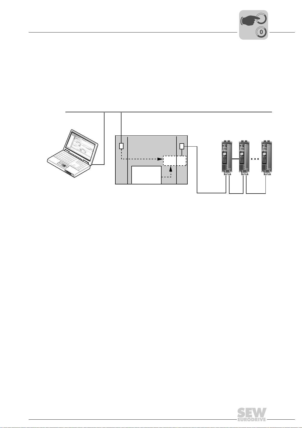
Operating MOVITOOLS® MotionStudio via EtherCAT
Phone: 800.894.0412 - Fax: 888.723.4773 - Web: www.clrwtr.com - Email: info@clrwtr.com
8.2 Required hardware
If an operating system that is compatible with MOVITOOLS® MotionStudio is available
on the EtherCAT master, no additional hardware is required.
If a compatible operating system is not installed, or if MOVITOOLS
be operated from another PC, the EtherCAT master requires a second Ethernet
interface with MOVITOOLS
lowing figure).
Required hardware
®
MotionStudio is to
®
MotionStudio that is connected to the PC via LAN (→ fol-
Ethernet TCP/IPEngineering LAN
MBX
I
8
00
MMS = MOVITOOLS
MBX = Mailbox gateway
8.3 Required software
MOVITOOLS® MotionStudio from version 5.40
8.4 Installation
Install MOVITOOLS® MotionStudio. If you are using MOVIDRIVE® B, you must also
install the MOVITOOLS
TCP/IP
®
MotionStudio
Windows
MMS
®
package.
Ether
CAT
EtherCAT
61475AXX
Manual – Fieldbus Interface DFE24B EtherCAT
75
Page 76

I
Phone: 800.894.0412 - Fax: 888.723.4773 - Web: www.clrwtr.com - Email: info@clrwtr.com
8
Operating MOVITOOLS® MotionStudio via EtherCAT
Configuring the mailbox gateway
00
8.5 Configuring the mailbox gateway
• Activate VoE/EoE support on the EtherCAT master.
• Specify the IP address of the EtherCAT mailbox gateway. The IP address is usually
assigned by the TwinCAT program and may not be changed.
The settings look as follows in Beckhoff’s TwinCAT program:
Figure 19: Set the IP address of the EtherCAT mailbox gateway
8.6 Network settings on the engineering PC
If MOVITOOLS® MotionStudio is running on the EtherCAT master, you do not have to
make any additional network settings.
If the EtherCAT master is connected to an Ethernet network, PCs in the same subnet
can access SEW drives on EtherCAT with MOVITOOLS
To do so, the telegrams from the engineering PC are routed via the Ethernet interface
of the EtherCAT master to the mailbox gateway.
61284AXX
®
MotionStudio (→ Sec. 8.2).
76
Manual – Fieldbus Interface DFE24B EtherCAT
Page 77

Operating MOVITOOLS® MotionStudio via EtherCAT
Phone: 800.894.0412 - Fax: 888.723.4773 - Web: www.clrwtr.com - Email: info@clrwtr.com
I
Network settings on the engineering PC
00
Two variants are available for routing:
1. Variant: Access to the mailbox gateway by specifying the standard gateway on the
engineering PC. In this variant, the IP address of the EtherCAT master is entered as
the standard gateway for TCP/IP communication.
Choose [Start] / [Settings] / [Network and DFÜ connections]. The "Network and DFÜ
connections" window opens. Make a right mouse click on a LAN connection. From
the context menu that opens choose "Properties". The "Properties of LAN connection" window opens. In the selection window, select the "Internet protocol (TCP/IP)"
checkbox. Next, click the "Properties" button. The "Properties of Internet protocol
(TCP/IP)" window opens. Select the "Use the following IP address" checkbox and
make the following entry (
Use the following IP address
IP address
Subnet mask
Standard gateway
→ below figure):
10 . 3 . 64 . 60
255 . 255 . 252 . 0
10 . 3 . 64 . 170
61942AXX
8
2. Variant: Access by defining a static route.
In this variant, an entry is added to the routing table of the engineering PC that routes
the engineering data via the EtherCAT master to the mailbox gateway.
In the DOS box, the command for creating a static route is as follows:
route –p add [Target] MASK [Netmask] [Gateway]
[Target]: Is the IP address of the EtherCAT mailbox gateway
[Net mask]: Is usually set to 255.255.255.255 (host routing)
[Gateway]: Matches the IP address of the EtherCAT master in the TCP/IP network
61941AXX
Manual – Fieldbus Interface DFE24B EtherCAT
77
Page 78

I
Phone: 800.894.0412 - Fax: 888.723.4773 - Web: www.clrwtr.com - Email: info@clrwtr.com
8
Operating MOVITOOLS® MotionStudio via EtherCAT
Configuring the SEW communication server
00
8.7 Configuring the SEW communication server
To be able to run MOVITOOLS® MotionStudio via EtherCAT, you must first configure
the SEW communication server.
8.7.1 Establishing communication
8.7.2 Procedure
MOVITOOLS
SEW-EURODRIVE GmbH & Co KG via different communication paths at the same
time.
When you start MOVITOOLS
automatically and an additional symbol will appear in the Windows status bar. .
Four steps are involved in configuring communication:
1. Open the settings for the SEW communication server by clicking on the "Communi-
cation connection" symbol in the toolbar (
"Network communication connections" menu.
2. Configure an Ethernet interface. To do so, choose the option "Ethernet" from the
drop-down list [1]. In the "Protocols" section, select the "Activate EtherCAT" checkbox [2]. Click the button "Setup EtherCAT" [3].
®
MotionStudio allows you to communicate with electronics products from
®
MotionStudio, the SEW communication server is started
→ following figure) or by selecting the
61932AXX
[1]
[2]
[3]
61936AXX
78
Manual – Fieldbus Interface DFE24B EtherCAT
Page 79

Operating MOVITOOLS® MotionStudio via EtherCAT
Phone: 800.894.0412 - Fax: 888.723.4773 - Web: www.clrwtr.com - Email: info@clrwtr.com
I
Configuring the SEW communication server
00
3. The "Set up Ethercat" window opens. Click the "+" button [1] and add the IP address
of the mailbox gateway to the EtherCAT master.
8
[1]
61937AXX
Observe the specified unit scan range in the basic settings (Fields "Scan range
from/to"). EtherCAT addresses 1001 to 1010 are scanned as standard. You must adjust
this unit scan range accordingly for large EtherCAT networks.
4. In the [Setting] / [Options] menu, select the menu item "Online mods". Check that the
option "Do not perform automatically" [1] is selected in the "Cyclic availability test"
field.
[1]
Manual – Fieldbus Interface DFE24B EtherCAT
61938AXX
79
Page 80

I
Phone: 800.894.0412 - Fax: 888.723.4773 - Web: www.clrwtr.com - Email: info@clrwtr.com
8
Operating MOVITOOLS® MotionStudio via EtherCAT
Automatic search for connected units (unit scan)
00
8.8 Automatic search for connected units (unit scan)
Press the <F5> function key or the "Online scan" symbol to perform an automatic
search through all communication channels and display the connected units in the unit
tree.
11651AXX
80
Manual – Fieldbus Interface DFE24B EtherCAT
Page 81

Operating MOVITOOLS® MotionStudio via EtherCAT
Phone: 800.894.0412 - Fax: 888.723.4773 - Web: www.clrwtr.com - Email: info@clrwtr.com
8.9 Activating online mode
• Perform the unit scan (see section 8.7).
• Use the mouse to highlight the required unit. Switch MOVITOOLS
online mode by pressing the "Online Mode" button (→ following figure).
Activating online mode
I
00
®
MotionStudio to
8
• Select the unit you want to operate and activate the plug-in menu with the right
mouse button.
8.10 Familiar problems during the operation of MOVITOOLS® MotionStudio
Check the following points if problems occur during configuration:
• Have you activated the EtherCAT protocol in the MOVITOOLS
communication settings?
• Is the correct IP address entered for the mailbox gateway in the EtherCAT master?
• Is it possible to address the EtherCAT mailbox gateway using the "ping" command?
• Is the setting made for the unit scan range sufficient?
• Is the online cyclic accessibility test activated in MOVITOOLS
®
MotionStudio
®
MotionStudio?
11652AXX
Manual – Fieldbus Interface DFE24B EtherCAT
81
Page 82

9
Phone: 800.894.0412 - Fax: 888.723.4773 - Web: www.clrwtr.com - Email: info@clrwtr.com
Error Diagnostics
Diagnostic procedures
9 Error Diagnostics
9.1 Diagnostic procedures
The diagnostic procedures described in the following section demonstrate the error
analysis methods for the following problems:
• Inverter does not operate on EtherCAT.
• Inverter cannot be controlled using the EtherCAT master.
For more information dealing specifically with the inverter parameter settings for various
fieldbus applications, refer to the Fieldbus Unit Profile manual and the MOVIDRIVE
parameter list.
Step 1: Check the connection between the inverter and EtherCAT
Is the bus connected plugged into the master / inverter? NO → [A]
YES
↓
How is the Link/activity LED reacting on option DFE24B? OFF →
ON
↓
Is the physical connection between the inverter and EtherCAT OK? Make
sure EtherCAT is connected correctly at X30 IN (incoming EtherCAT connection) / X31 OUT (outgoing EtherCAT connection).
YES
↓
Continue with 2: Response of the RUN LED?
NO →
®
[A]
[A]
[A] Check the bus cabling.
Step 2: Response of the RUN LED?
OFF
Flashing orange Bus in the master has not started. → [C]
Flashing green Slave is the the state PRE-OPERATIONAL. →
Lights up green
once
Lights up green Slave is the the state OPERATIONAL. → [C]
[A] Startup the bus in the master.
[B] Option DFE24B is defective.
Has the master switched the slave to the INIT
state?
Slave is the the state SAFE-OPERATIONAL.
YES →
NO →
→
[A]
[B]
[C]
[C]
[C] Continue with 3: Response of the ERR LED?
82
Manual – Fieldbus Interface DFE24B EtherCAT
Page 83

Step 3: Status of the ERR LED?
Phone: 800.894.0412 - Fax: 888.723.4773 - Web: www.clrwtr.com - Email: info@clrwtr.com
OFF Example 1: LED RUN lights up green (slave is in the state OPERATIONAL).
Error Diagnostics
Diagnostic procedures
↓
EtherCAT communication of the DFE24B option is in the operating state.
Example 2:
• LED RUN flashes green (slave is in the state PRE-OPERATIONAL)
• LED RUN lights up green once (slave is in the state SAFE-OPERATIONAL)
↓
Startup the bus in the master and activate the state OPERATIONAL in the slave.
↓
Start process data communication.
9
Flickering Prerequisite:
Flashes
red twice
Lights up
red once
• LED RUN flashes green (slave is in the state PRE-OPERATIONAL)
• LED RUN lights up green once (slave is in the state SAFE-OPERATIONAL)
A boot error has been detected. Boot option DFE24B.
If the ERR LED continues to flicker, option DFE24B is defective.
Example 1: LED RUN lights up green (slave is in the state OPERATIONAL).
Fieldbus timeout, activate process output data.
Example 2:
• LED RUN flashes green (slave is in the state PRE-OPERATIONAL)
• LED RUN lights up green once (slave is in the state SAFE-OPERATIONAL)
Watchdog timeout → start the bus in the master and activate the state
OPERATIONAL in the slave.
Start process data communication.
Prerequisite:
• LED RUN flashes green (slave is in the state PRE-OPERATIONAL)
• LED RUN lights up green once (slave is in the state SAFE-OPERATIONAL)
The status has changed automatically. Repair the configuration error and startup
the bus in the master again.
Activate OPERATIONAL state in the slave.
Start process data communication.
↓
↓
↓
↓
↓
↓
↓
↓
Manual – Fieldbus Interface DFE24B EtherCAT
83
Page 84

9
Phone: 800.894.0412 - Fax: 888.723.4773 - Web: www.clrwtr.com - Email: info@clrwtr.com
Error Diagnostics
Diagnostic procedures
Flashing Prerequisite:
• LED RUN flashes green (slave is in the state PRE-OPERATIONAL)
• LED RUN lights up green once (slave is in the state SAFE-OPERATIONAL)
Invalid configuration. Repair the configuration error and start the bus in the
master again.
Activate OPERATIONAL state in the slave.
Start process data communication.
↓
↓
↓
84
Manual – Fieldbus Interface DFE24B EtherCAT
Page 85

9.2 List of errors
Phone: 800.894.0412 - Fax: 888.723.4773 - Web: www.clrwtr.com - Email: info@clrwtr.com
• The following error list applies to option DFE24B in gateway operation.
• When operating option DFE24B in MOVIDRIVE
can be found in the MOVIDRIVE
Error Diagnostics
List of errors
®
®
MDX60B/61B operating instructions.
B, the corresponding error codes
9
Error
code
17 Stack overflow SBus communication
18 Stack underflow SBus communication
19 NMI SBus communication
20 Undefined
21 Protection fault SBus communication
22 Illegal word
23 Illegal instruc-
25 Eeprom SBus communication
28 Fieldbus timeout Default: PO data = 0
37 Watchdog error SBus communication
45 Initialization
111 Device Timeout
Designation Response Cause Measure
is stopped
is stopped
is stopped
Opcode
operand access
tion access
error
system error
SBus communication
is stopped
is stopped
SBus communication
is stopped
SBus communication
is stopped
is stopped
Error response
adjustable via P831
is stopped
SBus communication
is stopped
No Check the red system error LED LED
Malfunction of inverter electronics,
possibly due to EMC influence
Error while accessing EEPROM Activate factory settings, perform
No communication between master
and slave within the projected response
monitoring.
Error during execution of system software
Error after self-test during reset Perform a reset. Consult SEW
(H1) of DFx If this LED lights up red or
flashes, one or more stations on the
SBus were not addressed within the
timeout time. If the red system error
LED (H1) is flashing, the error is in the
DFx itself. In this case, error F111 was
only reported to the controller via fieldbus.
Check ground connections and
shielding and correct, if necessary.
Contact SEW service if this error
occurs again.
reset and reconfigure DFE. Contact
SEW service if the error occurs again.
• Check communication routine of
the master
• Extend the fieldbus timeout interval (response monitoring) in the
master configuration or deactivate
monitoring
Contact SEW Service.
Service if the error occurs again.
Check voltage supply, SBus cabling
and SBus terminating resistors.
Switch DFx off and on again. If the
error is still present, query the error
via diagnostic interface and perform
the action described in this table.
Manual – Fieldbus Interface DFE24B EtherCAT
85
Page 86

10
Phone: 800.894.0412 - Fax: 888.723.4773 - Web: www.clrwtr.com - Email: info@clrwtr.com
kVA
i
n
f
Technical Data
Option DFE24B for MOVIDRIVE® MDX61B
Hz
P
10 Technical Data
10.1 Option DFE24B for MOVIDRIVE® MDX61B
Option DFE24B (MOVIDRIVE® MDX61B)
Part number 1821 126 7
Power consumption P = 3 W
Standards IEC 61158, IEC 61784-2
Baud rate 100 MBaud full duplex
Connection technology 2 × RJ45 (8x8 modularJack)
Bus termination Not integrated because bus termination is activated automatically.
OSI layer EtherNet II
Station address Set via the EtherCAT master (→ display using P093)
Name of the XML file SEW_DFE24B.xml
Vendor ID 0x59 (CANopenVendor ID)
EtherCAT services • CoE (CANopen over EtherCAT)
Firmware status
MOVIDRIVE
Tools for startup • PC program MOVITOOLS
®
B
• VoE (Simple MOVILINK-Protocol over EtherCAT)
824 854 0.18 or above (→ display using P076)
• DBG60B keypad
®
MotionStudio from version 5.40
86
Manual – Fieldbus Interface DFE24B EtherCAT
Page 87

Technical Data
Phone: 800.894.0412 - Fax: 888.723.4773 - Web: www.clrwtr.com - Email: info@clrwtr.com
Option DFE24B for MOVITRAC® B and Universal Gateway Housing
kVA
i
n
f
Hz
P
10.2 Option DFE24B for MOVITRAC® B and Universal Gateway Housing UOH11B
4.5
5.5
DFE 24B
RUN
ERR
01
AS
F1
224
INX30OUTX31
OUTX31
EtherCAT
257.5
234.5
185
10
28
30
22.5
100
59796AXX
Figure 20: Dimensions of the UOH11B gateway housing
Option DFE24B (MOVITRAC® B gateway)
External voltage supply U = DC 24 V (–15 %, +20 %)
Standards IEC 61158, IEC 61784-2
Baud rate 100 MBaud full duplex
Connection technology 2 × RJ45 (8x8 modularJack)
Bus termination Not integrated because bus termination is activated automatically.
OSI layer EtherNet II
Station address Set via the EtherCAT master (→ display using P093)
Name of the XML file SEW_DFE24B.xml
Vendor ID 0x59 (CANopenVendor ID)
EtherCAT services • CoE (CANopen over EtherCAT)
Firmware status
MOVIDRIVE
Tools for startup • PC program MOVITOOLS
®
B
= DC 200 mA
I
max
= 3.4 W
P
max
• VoE (Simple MOVILINK-Protocol over EtherCAT)
No special firmware is required
®
• FBG60B keypad
MotionStudio from version 5.40
Manual – Fieldbus Interface DFE24B EtherCAT
87
Page 88

11
Phone: 800.894.0412 - Fax: 888.723.4773 - Web: www.clrwtr.com - Email: info@clrwtr.com
Index
11 Index
A
Additional code
Auto setup for gateway operation
B
Baud rate
Bus cable
Routing
shielding
Bus termination
C
Configuration
EtherCAT master for MOVIDRIVE® B
with XML file
EtherCAT master for MOVITRAC® or
gateway with XML file
Procedure
Return codes
Via EtherCAT
Configuration of the EtherCAT option card
Configuration of the mailbox gateway
Configuration return codes
Connection
Option DFE24B
Connection technology
Control
MOVIDRIVE® MDX61B
MOVITRAC® B
Control example
D
Data exchange via EtherCAT
DFE24B
Connection
Operating displays
Terminal description
DFE24B operating displays
Diagnostics
E
Error class
Error code
Error diagnostics
EtherCAT
Configuration
Data exchange
Functions
LEDs
Operating characteristics
Option card configuration
Timeout
EtherCAT operating characteristics
Explanation of symbols
...................................................57
.......................41
............................................................17
.........................................................21
.......................................................21
......................................21, 86, 87
.................................................25
...................................35
.............................................. 26, 35
................................................56
...............................................52
.................76
..................................56
..........................................................16
............................................19
................................ 86, 87
...............................45
............................................49
..................................................46
.............................11
...................................................19
........................................22
.....................................19
................................22
.........................................................12
...........................................................56
...........................................................56
.................................................82
................................................52
.............................................11
......................................................58
.............................................................22
..............................45
.............................11
........................................................48
....................45
.........................................6
.........11
F
Fieldbus monitor
Functions
EtherCAT
G
GSD file
I
Installation
L
LEDs, EtherCAT
Liability for defects
M
Mailbox gateway
Monitoring functions
Motion control via EtherCAT
MOVIDRIVE® MDX61B
MOVITOOLS® MotionStudio
MOVITRAC® B
N
Notes
O
Online mode, activation
Option cards
P
Part number
.............................................................. 86
Validity for DFE24B
Installing and removing option cards
Option card DFE24B in MOVITRAC® B
Option card DFE24B in
MOVIDRIVE® MDX61B
UOH11B gateway housing
Configuration
Example in TwinCAT
Introduction
Position mode
Settings in EtherCAT master
Settings in MOVIDRIVE® with
MOVITOOLS® MotionStudio
Synchronization
Velocity mode
Control
Setting the drive inverter
Operation via EtherCAT
Control
Setting the frequency inverter
Assembly / installation
Documentation
Important notes
Safety
Installation and removal
................................................ 12
..................................................... 58
..................................... 25
.............................. 13
.......................... 18
................................................ 22
............................................... 7
............................................... 76
........................................... 12
.............................. 58
................................... 69
.................................................. 58
.............................................. 62
....................... 67
....................... 63
........................................... 59
.............................................. 61
......................................................... 45
.............................. 42
.............................. 74
......................................................... 49
...................... 43
................................. 13
.............................................. 6
.............................................. 6
............................................................ 8
..................................... 81
............................... 14
....................................................... 86
........... 14
...... 15
88
Manual – Fieldbus Interface DFE24B EtherCAT
Page 89

Pin assignment of an RJ45 plug connector ........20
Phone: 800.894.0412 - Fax: 888.723.4773 - Web: www.clrwtr.com - Email: info@clrwtr.com
Position mode
Process data object (PDO) configuration
For cyclical EtherCAT operation of
MOVIDRIVE® MDX61B
Putting into storage
S
Safety notes
Assembly / installation
Bus systems
Startup / operation
Transportation / putting into storage
SBus
Timeout
SDO services
READ and WRITE
Setting
MOVIDRIVE® MDX61B drive inverter
MOVITRAC® B frequency inverter
Settings in MOVIDRIVE® with
MOVITOOLS® MotionStudio
SEW communication server
Station address
Settings
Synchronization
System bus
.....................................................62
...............................27
...............................................8
..........................................................8
....................................9
...................................................8
..........................................9
...............8
........................................................51
........................................52
.........42
...............43
..............................63
................................78
............................................ 86, 87
........................................................21
..................................................59
.........................................................16
Index
11
T
Technical data
Option DFE24B for gateway housing
UOH11B
Option DFE24B for MOVIDRIVE® MDX61B
Option DFE24B for MOVITRAC® B
Terminal description
Option DFE24B
Timeout
EtherCAT
SBus
Transportation
TwinCAT
U
Unit scan
V
Velocity mode
X
XML file
For EtherCAT
For operation in gateway housing UOH11B
For operation in MOVITRAC® B
.......................................................87
............................................19
......................................................48
.............................................................51
.......................................................8
.............................................................46
.............................................................80
.....................................................61
...............................................................87
...............................................25
..................35
86
.............87
.35
Manual – Fieldbus Interface DFE24B EtherCAT
89
 Loading...