

SEW-Eurodrive Varimot 16-46 Series, D 16, D 26, D 36, DF16D Operating Instructions Manual
...Page 1
Gearmotors \ Industrial Gear Units \ Drive Electronics \ Drive Automation \ Services
Explosion-Proof
VARIMOT
and Accessories
Edition 11/2006
11529016 / EN
®
Variable Speed Gear Units
O
perating
I
nstructions
Page 2

SEW-EURODRIVE – Driving the world
Page 3

Contents
1 Important Information about the Operating Instructions .............................. 4
1.1 Explanation of symbols ............................................................................. 6
2 Safety Notes ...................................................................................................... 7
2.1 Safety notes for the use of VARIMOT
®
3 VARIMOT
in Explosion-Proof Version .......................................................... 8
3.1 Unit design ............................................................................................... 8
3.2 Unit designation ........................................................................................ 9
3.3 Nameplate............................................................................................... 10
3.4 Overview of mounting options................................................................. 11
4 Installation ....................................................................................................... 12
4.1 VARIMOT
4.2 VARIMOT
®
in category 2G ..................................................................... 12
®
in categories 3G and 3D...................................................... 13
4.3 Permitted overhung loads without primary gear unit............................... 13
4.4 Before you begin..................................................................................... 16
4.5 Preliminary work...................................................................................... 16
4.6 Installation............................................................................................... 17
4.7 Gear units with solid shafts ..................................................................... 19
®
..................................................... 7
5 Startup.............................................................................................................. 21
5.1 Installation and setup of optional equipment........................................... 21
6 Inspection and Maintenance .......................................................................... 32
6.1 Inspection and maintenance intervals..................................................... 32
6.2 Before you begin..................................................................................... 33
6.3 Checking torsional play........................................................................... 33
6.4 Checking the friction ring......................................................................... 34
6.5 Replacing the friction ring........................................................................ 35
6.6 Measuring the temperature of the anti-friction bearing ........................... 36
6.7 Completing the inspection/maintenance process ................................... 37
7 Operation and Service .................................................................................... 38
7.1 Customer service .................................................................................... 38
7.2 Malfunction of VARIMOT
®
speed gear units........................................... 38
7.3 WEXA/WEX speed monitor..................................................................... 39
8 Declaration of Conformity .............................................................................. 40
8.1 Variable speed gear units category 2G, VARIMOT
8.2 Variable speed gear units category 3G and 3D,
VARIMOT
®
series 16-46......................................................................... 41
®
series 16-46 ......... 40
9 Index................................................................................................................. 42
Operating Instructions – Explosion-Proof VARIMOT® Variable Speed Gear Units and Accessories
3
Page 4

1
Important Information about the Operating Instructions
1 Important Information about the Operating Instructions
Introduction You must follow the information in the operating instructions to ensure trouble-free oper-
ation and for the fulfillment of any rights to claim under the limited warranty. Read the
operating instructions before you start working with the unit.
Make sure that the operating instructions are available to persons responsible for the
system and its operation, as well as to persons who work independently on the unit.
Also observe other technical documents, contracts for delivery or other agreements.
Intended use
Qualified personnel
VARIMOT
systems and may only be used in accordance with the information provided in SEWEURODRIVE's technical documentation and the information given on the nameplate.
It corresponds to valid standards and regulations and meet the requirements of
EC Directive 94/9/EC and the EC Directive for Machinery 98/37/EC.
Gear unit loads other than those specified and areas of application other than industrial
and commercial systems can only be used after consultation with SEW-EURODRIVE.
Any application other than those mentioned is considered non-intended use.
A drive motor connected to the VARIMOT
inverter.
VARIMOT
material. Consequently, assembly, installation, startup and service work may only be
performed by trained personnel who are aware of the potential hazards.
Personnel must possess the required qualifications for the relevant task and be familiar
with the:
• Assembly
• Installation
•Startup
•Operation
• Maintenance
• Servicing
of the product.
Personnel must carefully read the operating instructions, in particular the safety notes
section, and understand and comply with them.
®
variable speed gear units are intended for commercial and industrial
®
may not be operated on the frequency
®
variable speed gear units represent a potential hazard for persons and
4
Operating Instructions – Explosion-Proof VARIMOT® Variable Speed Gear Units and Accessories
Page 5

Important Information about the Operating Instructions
Exclusion of liability
You must comply with the information contained in these operating instructions to
ensure safe operation of the VARIMOT
specified product characteristics and performance requirements.
SEW-EURODRIVE GmbH & Co KG assumes no liability for injury to persons or damage
to equipment or property resulting from non-observance of these operating instructions.
In such cases, any liability for defects is excluded.
Product names and trademarks
The brands and product names contained within these operating instructions are trademarks or registered trademarks of the titleholders.
Waste disposal (Please follow the current instructions):
• Housing parts, gears, shafts and anti-friction bearings of the gear unit must be disposed of as steel scrap. This also applies to gray-cast iron parts if there is no special
collection.
• Collect waste oil and dispose of it according to the regulations in force.
®
1
variable speed gear unit and to achieve the
Operating Instructions – Explosion-Proof VARIMOT® Variable Speed Gear Units and Accessories
5
Page 6
1
Important Information about the Operating Instructions
Explanation of symbols
1.1 Explanation of symbols
The operating instructions contain important information that deals with general and
operational safety. This information is emphasized in particular with the following
symbols.
Electrical hazard
Possible consequences: Severe or fatal injuries.
Hazard
Possible consequences: Severe or fatal injuries.
Hazardous situation
Possible consequences: Slight or minor injuries.
Harmful situation
Possible consequences: Damage to the drive and the environment.
Tips and useful information.
Important information about explosion protection.
6
Operating Instructions – Explosion-Proof VARIMOT® Variable Speed Gear Units and Accessories
Page 7
2 Safety Notes
Safety Notes
Safety notes for the use of VARIMOT®
2
2.1 Safety notes for the use of VARIMOT
The following safety notes apply to variable speed gear units.
When using variable speed gearmotors, also refer to the safety notes for gear units
and motors in the relevant operating instructions.
Take into consideration the supplementary safety notes in the individual sections
of these operating instructions.
Explosive gas mixtures or dust concentrations when combined with hot, live, and
moving parts of electrical machinery can cause serious injury or death.
Assembly, connection, startup, maintenance and repair work on the VARIMOT
variable speed gear units and the optional electrical components may only be
performed by qualified personnel while taking the following into account:
• These operating instructions
• Warning and instruction labels on the variable speed gear unit/variable speed gearmotor
• All other project planning documents, operating instructions and wiring diagrams
belonging to the drive
• The specific regulations and requirements for the system
• National/regional regulations on explosion protection, safety, and prevention of accidents that are currently in effect
®
®
Optional
equipment
Optional equipment complies with existing standards and regulations:
• EN 50014
• EN 50018 for protection type "d"
• EN 50019 for protection type "e"
• EN 50020 intrinsically safe "i"
• EN 50281-1-1/EN 50281-1-2 "Electrical apparatus for use in the presence of
combustible dust"
In addition to general installation guidelines, the following regulations in accordance with
ElexV 1 (or other national regulations) must be observed for electrically operated
options:
• EN 60079-14 "Electrical apparatus for explosive gas atmospheres"
• EN 50281-1-2 "Electrical apparatus for use in the presence of combustible dust"
• DIN VDE 105-9 "Operating electrical equipment" or other national regulations
• DIN VDE 0100 "Erection of power installations with rated voltages below 1000 V" or
other national regulations
• System-specific regulations
Technical data and information on approved conditions on site can be found on the
nameplate and in these operating instructions.
These details must be strictly observed.
Operating Instructions – Explosion-Proof VARIMOT® Variable Speed Gear Units and Accessories
7
Page 8
3
[1]
[9]
[5]
[4][6] [10]
[7]
[3]
[8]
VARIMOT® in Explosion-Proof Version
Unit design
3 VARIMOT® in Explosion-Proof Version
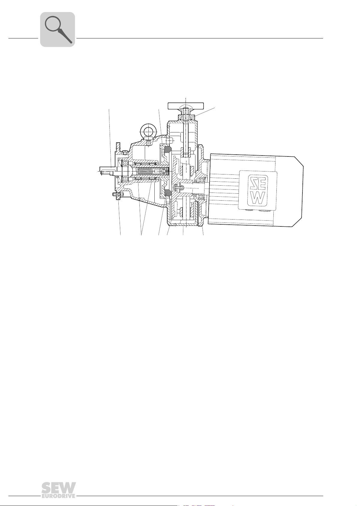
3.1 Unit design
Fig. 1: VARIMOT® in explosion-proof version
52018AXX
[1] Complete output shaft
[3] Plate
[4] Adjusting plate
[5] Housing cover
[6] Drive disk
[7] Needle bearing
[8] Housing with tapped hole
[9] Complete hollow shaft
[10] Friction ring
8
Operating Instructions – Explosion-Proof VARIMOT® Variable Speed Gear Units and Accessories
Page 9
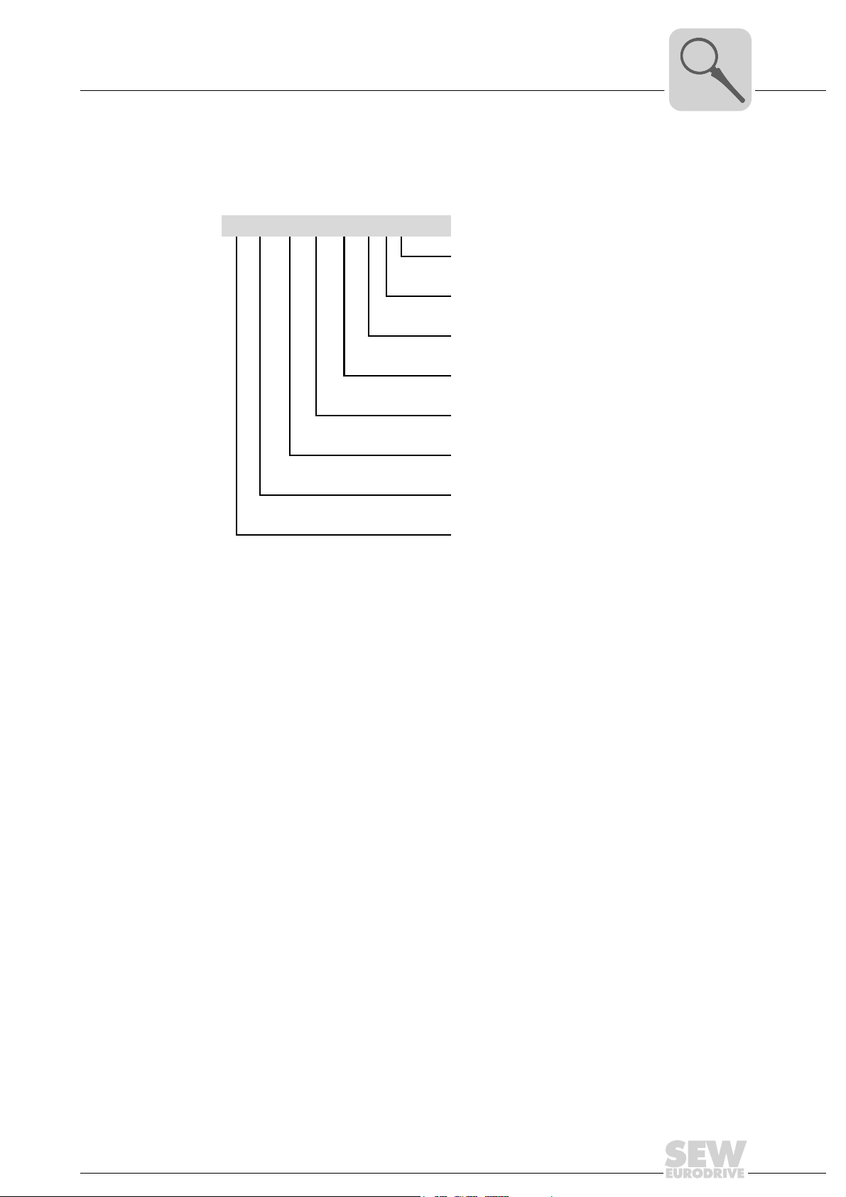
3.2 Unit designation
The following diagram shows the type code structure:
DV 26B WEX II2G eDT 90L 4 TF
VARIMOT® in Explosion-Proof Version
Unit designation
Temperature sensor
Number of motor poles
Motor size
Motor series
Explosion-proof version according to ATEX 100a
Speed monitor
3
VAR IMOT
indicates wet version
VAR IMOT
version
®
variable speed gear unit size B
®
variable speed gear unit series flange
Operating Instructions – Explosion-Proof VARIMOT® Variable Speed Gear Units and Accessories
9
Page 10

3
3.3 Nameplate
Example
VARIMOT® in Explosion-Proof Version
Nameplate
Bruchsal / Germany
DF36/A/IGEX/II2G
Typ
01.1151703702.0001.06
Nr.
159/798
r/min
n
a
M
Nm
84/38
a
IM
M4
Bedienungsanleitung muss beachtet werden
Zum Einbau in Komplettantrieb
RX77 D36/IGEX/II2G eDV112M4/C
II2G / T3
Lagerfett synth. KHC2R
Fig. 2: Nameplate
R
n
P
kg
i
Made in Germany 150 881 4.10
1:
5
r/min
e
1440
3.6
kW
e
104.242
=
168
60417AXX
Typ Type code
Nr. Sales order number
Minimum and maximum output speed
n
a
Output torque at minimum and maximum output speed
M
a
IM Mounting position
R Control range
Input speed
n
e
Input power
P
e
kg Weight
i Gear ratio
10
Operating Instructions – Explosion-Proof VARIMOT® Variable Speed Gear Units and Accessories
Page 11
VARIMOT® in Explosion-Proof Version
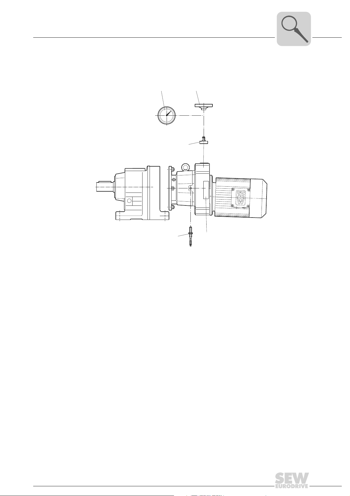
3.4 Overview of mounting options
Overview of mounting options
3
[2]
[5]
Fig. 3: Overview of mounting options
[3]
[1]
[4]
52019AXX
[1] Adjustment device with free shaft end NV
[2] Adjustment device with handwheel and position indication HS
[3] Adjustment device with handwheel (standard version)
[4] Indicator scale
[5] Voltage encoder IGEX
Operating Instructions – Explosion-Proof VARIMOT® Variable Speed Gear Units and Accessories
11
Page 12
4
Installation
VARIMOT® in category 2G
4 Installation
Strictly observe the safety notes on page 7 when installing the variable speed
gear unit.
4.1 VARIMOT® in category 2G
General
information
Designation "X" • If the designation "X" appears after the certification number on the declaration of
Temperature class • VARIMOT
Ambient
temperature
Output power and
output torque
Speed monitoring • VARIMOT
• SEW explosion-proof variable speed gear units of the VARIMOT® D/DF 16-46 series
and VARIMOT
group II, category 2G (explosive gas atmosphere). These units are intended for use
in zones 1 and 2.
• A standard feature of the SEW-EURODRIVE explosion-proof variable speed gear
units of the VARIMOT
conformity or the EC prototype test certificate, this indicates the certificate contains
special conditions for safe application of the variable gear unit.
approved for temperature class T3. The temperature class of the variable speed gear
unit is indicated on the nameplate.
• VARIMOT
of –20°C (–4°F) to +40°C (+104°F).
• It is essential that nominal values of output power and/or output torque are maintained.
speed monitoring device. The speed monitor must be correctly installed and adjusted
(see Sec. "Startup", Speed monitoring).
Verify the speed monitoring function before startup.
®
D/DF 16-46B series meet the design requirements of equipment
®
series is a tapped hole for installing a voltage encoder.
®
variable speed gear units, category 2G (explosive gas atmosphere) are
®
variable speed gear units may only be used at an ambient temperature
®
variable speed gear units in category 2G may only be operated with a
12
Operating Instructions – Explosion-Proof VARIMOT® Variable Speed Gear Units and Accessories
Page 13
VARIMOT® in categories 3G and 3D
F
R
d
l
l/2
4.2 VARIMOT® in categories 3G and 3D
General
information
Temperature class • VARIMOT
Surface
temperature
Ambient
temperature
Output power and
output torque
• SEW-EURODRIVE explosion-proof variable speed gear units of the VARIMOT
D/DF 16-46 and VARIMOT® D/DF 16-46B series meet the design requirements of
equipment group II, categories 3G (explosive gas atmosphere) and 3D (explosive
dust atmospheres). These units are intended for use in zones 2 and 22.
• A standard feature of the SEW-EURODRIVE explosion-proof variable speed gear
units of the VARIMOT
®
variable speed gear units of category 3G (explosive gas atmosphere)
®
series is a tapped hole for installing a voltage encoder.
are approved for temperature class T3. The temperature class of the variable speed
gear unit is indicated on the nameplate.
• The maximum surface temperature of VARIMOT
gory 3D (explosive dust atmosphere) may not exceed 200 °C (392 °F). The system
operator must guarantee that a possible accumulation of dust will not exceed a
maximum thickness of 5 mm, in accordance with EN 50281-1-2.
• VARIMOT
®
variable speed gear units may only be used at an ambient temperature
of –20°C (–4°F) to +40°C (+104°F).
• It is essential that nominal values of output power and/or output torque are
maintained.
Installation
®
variable speed gear units, cate-
4
®
If an overload condition of the VARIMOT® as category 3G or 3D unit cannot be
ruled out during normal operation, a VARIMOT
monitor must be used (see Sec. "Startup", Speed monitoring).
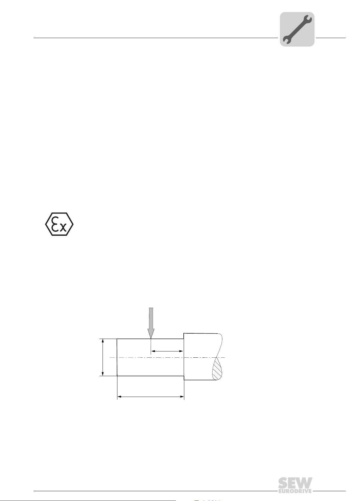
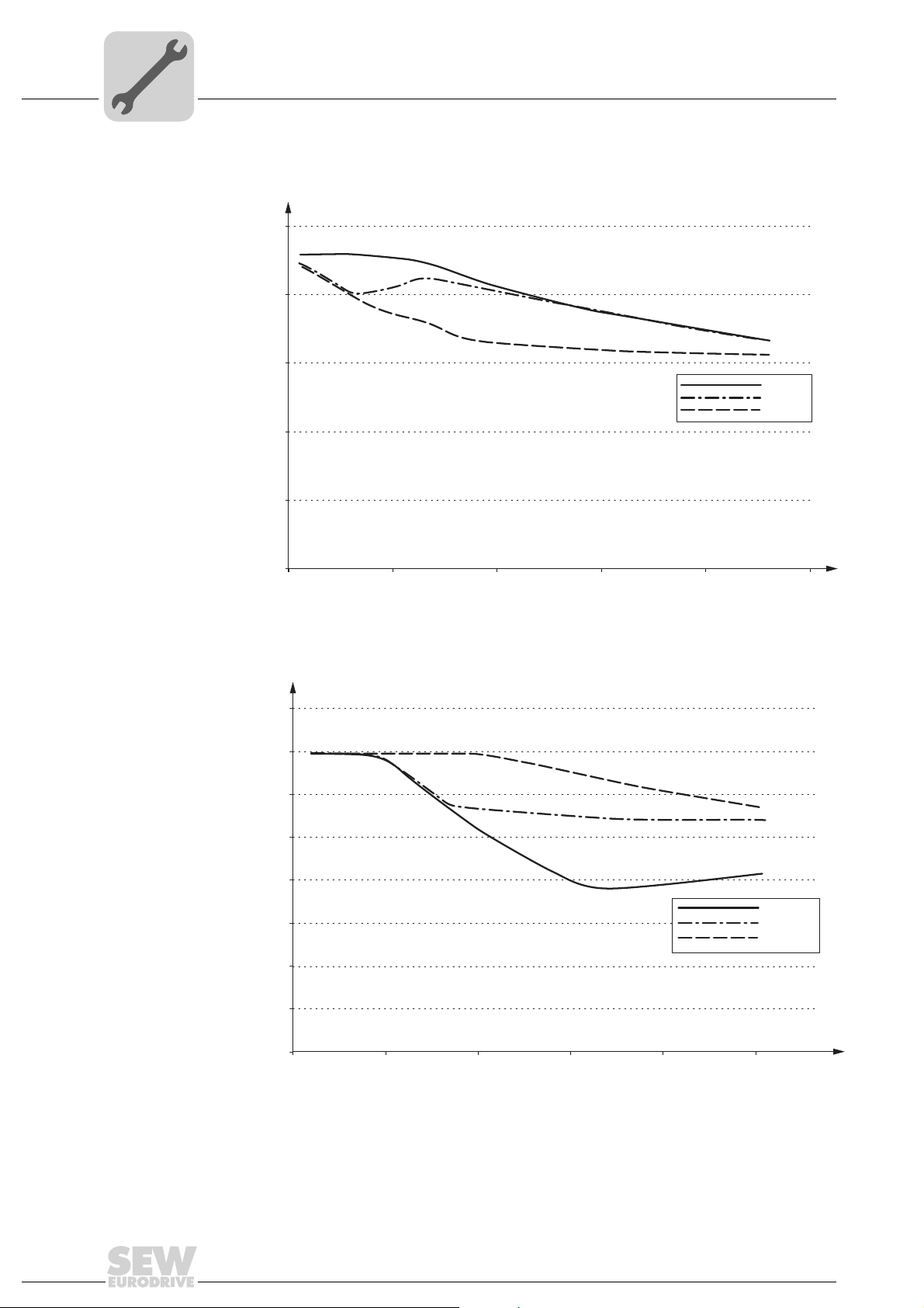
4.3 Permitted overhung loads without primary gear unit
Definition of force
application of
overhung loads
The development of the overhung load depicted in the diagrams refers to a point of
application at mid-point of the shaft extension as indicated in Figure 1. If force is applied
to areas other than the center of the shaft end, consult SEW-EURODRIVE for permitted
lateral forces.
®
unit with a functioning speed
Fig. 4: Definition of force application of overhung loads
F
[N] = permitted overhung load point of application at mid-point of shaft extension.
R
Operating Instructions – Explosion-Proof VARIMOT® Variable Speed Gear Units and Accessories
50248AXX
13
Page 14
4
VARIMOT® D16
n [1/min]
FR [N]
0
500
1000
1500
2000
2500
300 600 900 1200 1500 1800
DT71D4
DT80K4
DT80N4
Installation
Permitted overhung loads without primary gear unit
FR [N]
4000
3500
3000
2500
2000
1500
1000
500
0
300 600 900 1200 1500 1800
VARIMOT® D26
51908AXX
DV100M4
DT90L4
DT90S4
n [1/min]
51909AXX
14
Operating Instructions – Explosion-Proof VARIMOT® Variable Speed Gear Units and Accessories
Page 15
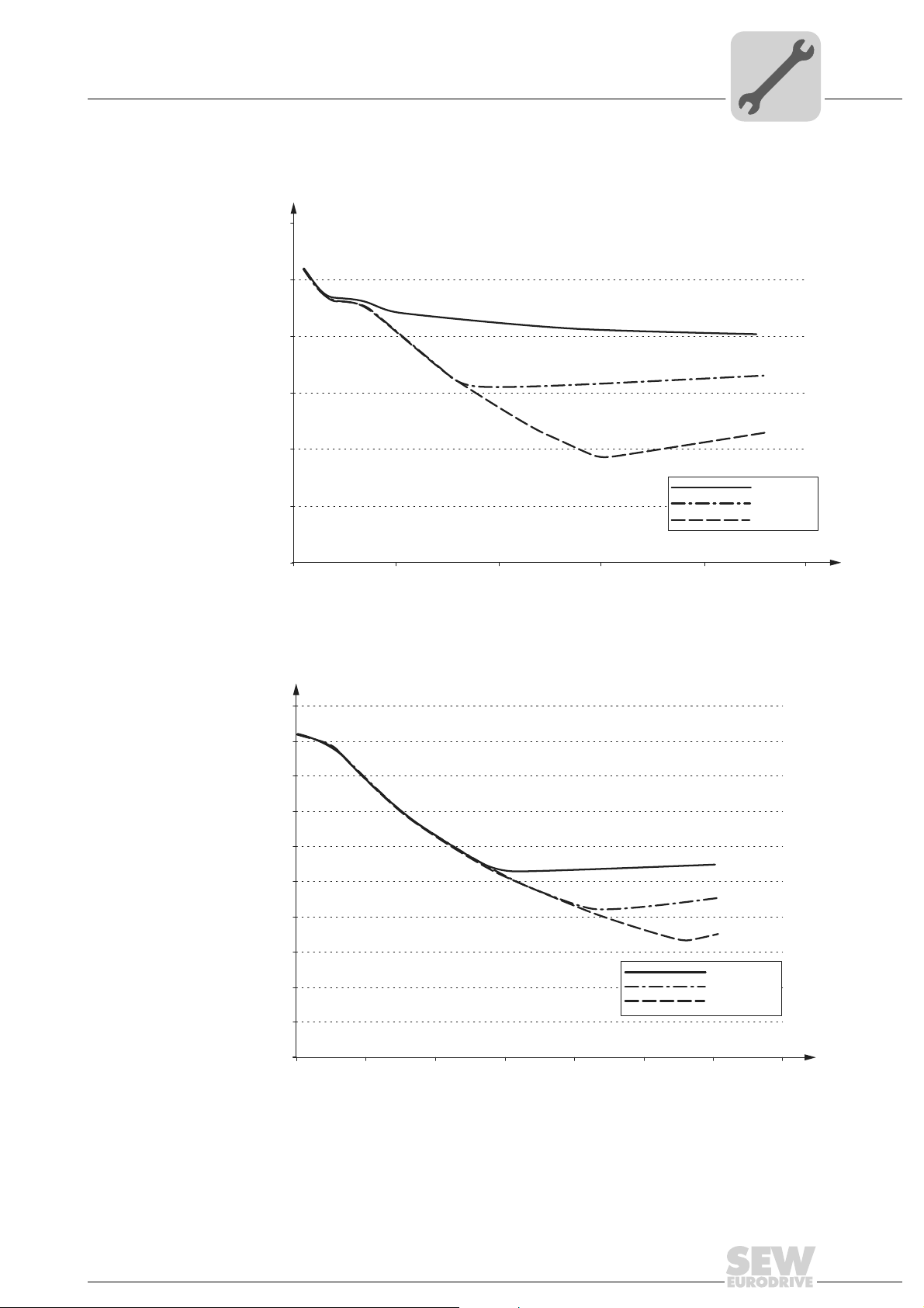
Installation
FR [N]
VARIMOT® D36
n [1/min]
0
1000
2000
3000
4000
5000
6000
300 600 900 1200
1500
1800
DV100L4
DV112M4
DV132S4
[
]
Permitted overhung loads without primary gear unit
4
FR [N]
10000
9000
8000
7000
6000
5000
4000
3000
2000
1000
0
400 600 800 1000 1200 1400 1600 1800
VARIMOT® D46
DV132M4
DV132ML4
DV160M4
51911AXX
1/min
n
51912AXX
Operating Instructions – Explosion-Proof VARIMOT® Variable Speed Gear Units and Accessories
15
Page 16
4
4.4 Before you begin
Installation
Before you begin
The drive
may only be
installed if
• The information on the nameplate of the drive matches the approved on-site explosion application range (equipment group, category, zone, temperature class or maximum surface temperature).
• The information on the nameplate of the drive matches the voltage supply system.
• The drive is undamaged (no damage caused by transportation or storage).
• It is certain that the following requirements have been met:
• Ambient temperature between –20 °C (–4 °F) and +40 °C (+104 F°)
• No oils, acids, gas, vapors, radiation, potentially explosive atmospheres, etc.
• Enclosure has been verified.
4.5 Preliminary work
Variable speed
gear units
Risk of material damage
Do not let the solvent come into contact with the sealing lips of the oil seals or on
the wide V-belt.
The output shafts and flange surfaces must be thoroughly cleaned of anti-corrosion
agents, contamination or such (use a commercially available solvent).
Anti-friction
bearing grease
Please note:
• The service life of the lubricant in the bearings is reduced if the unit is stored for
à 1 year.
Ambient temperature Base Original filling Brand
Gear unit anti-friction
bearing
–20 °C (–4 °F) to +40 °C
(+104 °F)
Synthetic Mobiltemp SHC 100 Mobil
16
Operating Instructions – Explosion-Proof VARIMOT® Variable Speed Gear Units and Accessories
Page 17

4.6 Installation
Installation in
damp locations
or outdoors
Installation
Installation
• The variable speed gearmotor may only be mounted or installed on a level1), vibration-damping and torsionally rigid support structure. Do not tighten housing legs and
mounting flanges against each other.
• VARIMOT® version HS (handwheel with position indication) must be mounted
so that the adjusting spindle is horizontal; otherwise the position indication
will not function properly.
• The breather valves must be easily accessible. The plastic plug of the condensation drain hole at the lowest position must be removed before operation
(danger of corrosion).
• Carefully align the variable speed gear drives to avoid overloading the output shafts
(observe permitted overhung loads and axial forces).
• Do not hit or hammer the shaft end.
• Ensure an unobstructed cooling air supply and that air heated by other apparatus
cannot be drawn in and reused. The cooling air may not exceed a temperature of
40 °C (104 °F).
• VARIMOT
in damp areas or outdoors. Any damage to the coating (e.g. on the breather valve)
must be repaired.
®
gear units are supplied in corrosion-resistant versions (version B) for use
4
Cable entry,
cable gland
Painting the
gear unit
• All cable entries are provided with ATEX certified plugs.
• To establish the correct cable entry, the plugs are replaced by ATEX certified
cable glands with strain relief.
• Select the cable gland according to the outer diameter of the cable used.
• All non-required cable entries must be sealed with an ATEX certified plug after
installation is completed.
• Coat the threads of cable glands and filler plugs with sealing compound and tighten
them well – then coat them again. Properly seal the cable entry.
• Properly clean the sealing surfaces of the terminal box and terminal box cover before
reassembly. Replace brittle gaskets.
If all or some of the surfaces of the drive are to be painted, make sure that you carefully
mask over the breather valve and the oil seals. Remove the strips of tape after completing the painting work.
1 Maximum permitted flatness error for flange mounting (approximate values with reference to DIN ISO 1101):
with Æ flange 120 ... 600 mm max. error 0.2 ... 0.5 mm
Operating Instructions – Explosion-Proof VARIMOT® Variable Speed Gear Units and Accessories
17
Page 18

4
Installation
Installation
Required tools/
resources
Installation
tolerances
• Set of wrenches
• Mounting device
• Compensation elements (shims, spacing rings), if necessary
• Mounting materials for output components
Shaft end Flanges
Diameter tolerance in accordance with DIN 748
• ISO k6 for solid shafts with d, d
• ISO k7 for solid shafts with d, d
• Center bore in accordance with DIN 332, shape DR.
 50 mm
1
> 50 mm
1
Centering shoulder tolerance in accordance with
DIN 42948
• ISO j6 at b1 Â 230 mm
• ISO h6 with b
1
> 230 mm
18
Operating Instructions – Explosion-Proof VARIMOT® Variable Speed Gear Units and Accessories
Page 19

4.7 Gear units with solid shafts
Only use ATEX approved input and output components.
Input and output elements such as belt pulleys, couplings, etc. must have protection against contact.
• Never drive belt pulleys, couplings, pinions, etc. onto the shaft end by hitting
them with a hammer (this will cause damage to bearings, housing and the
shaft).
• With belt pulleys, ensure the belt is correctly tensioned according to manufacturer's specifications.
Assembly is easier if you first apply lubricant to the output element or heat it up briefly
(to 80 – 100 °C [176 – 212 °F]).
Installation
Gear units with solid shafts
4
Mounting of input
and output
components
The following figure shows an example of a mounting device for installing couplings or
hubs on variable speed gear unit or motor shaft ends. You can remove the thrust bearing
on the mouthing device, if necessary.
[1]
[3]
Fig. 5: Example of a mounting device
[1] Gear shaft end [3] Coupling hub
[2] Thrust bearing
[2]
52020AXX
Operating Instructions – Explosion-Proof VARIMOT® Variable Speed Gear Units and Accessories
19
Page 20

4
[1]
[1]
a)
b) c)
Installation
Gear units with solid shafts
The following illustration shows the correct mounting arrangement (B) of a gear wheel
or chain sprocket for avoiding impermissibly high overhung loads.
Mounting
couplings
Fig. 6: Correct mounting arrangement of a gear or sprocket wheel
52021AXX
A Incorrect [1] Hub
BCorrect
• Do not install input and output elements without a mounting device. Use the center
bore with the thread on the shaft end for positioning.
• Power transmission elements should be balanced after fitting and must not give rise
to any excessive radial or axial forces (see the "Geared Motors" catalog for permitted
values).
Couplings must be mounted and balanced according to the information provided
by the coupling manufacturer:
a) Maximum and minimum clearance
b) Axial offset
c) Angular offset
20
Fig. 7: Clearance and misalignment for coupling mounting
Operating Instructions – Explosion-Proof VARIMOT® Variable Speed Gear Units and Accessories
03356AXX
Page 21

Installation and setup of optional equipment
00
I
5Startup
5.1 Installation and setup of optional equipment
Speed monitoring
Category 2G variable speed gear units may only be started up with speed monitoring.
Startup
5
Standard version The standard version of the explosion-proof VARIMOT
tures an M14x1 tapped hole (flange mounted VARIMOT
strips in the terminal box) or M18x1 (flange mounted VARIMOT
plug connector) for installing a voltage encoder in the gear unit housing of the variable
speed gear unit. Speed monitor and voltage encoder must be supplied and installed by
the operator of the device.
Additional
versions:
Manufacturer's
data
The following additional version of speed monitoring are possible:
1. WEXA:
• Speed monitor (incl. evaluation electronics) with IGEX voltage encoder and digital
remote speed indicator.
2. WEX:
• Speed monitor (incl. evaluation electronics) with IGEX voltage encoder.
3. IGEX:
• This version consists only of the IGEX voltage encoder in the scope of delivery.
The speed monitor must be supplied and installed by the operator of the device.
Voltage encoder in WEXA/WEX/IGEX version for VARIMOT
Manufacturer: Pepperl + Fuchs, Mannheim
Type:
Housing: M14x1
ATEX certification number: TÜV 99 ATEX 1471
Voltage encoder in WEXA/WEX/IGEX version for VARIMOT
NJ2-11-N-G according to DIN 19234 (NAMUR),
100 mm connection cable
®
variable speed gear unit fea-
®
D16/26, version with terminal
®
D36/46, version with
®
D16/26:
®
D36/46:
Manufacturer: Pepperl + Fuchs, Mannheim
Type:
Housing: M18x1
ATEX certification number: TÜV 99 ATEX 1471
NJ5-18GM-N-V1 according to DIN 19234
(NAMUR), M12x1 plug-in connection
Operating Instructions – Explosion-Proof VARIMOT® Variable Speed Gear Units and Accessories
21
Page 22

5
00
I
Startup
Installation and setup of optional equipment
Speed monitor in WEXA/WEX version:
Manufacturer: Pepperl + Fuchs, Mannheim
Type: KFU8-UFC-Ex1.D
Auxiliary power: DC 20 - 90 V / AC 48 - 253 V
ATEX certification number: TÜV 99 ATEX 1471
All installation and setting notes given below refer to the speed monitor or voltage
encoder in WEXA/WEX version.
If other speed monitors in the WEXA/WEX version are used, they must be installed
and started up according to the manufacturer’s documentation.
22
Operating Instructions – Explosion-Proof VARIMOT® Variable Speed Gear Units and Accessories
Page 23

Installation and setup of optional equipment
1
7 8 11 12 13 14 16 17 1810
23
+
+
+
-
-
-
19 20 23 24
DC 20-90 V
AC 48-253 V
0/4-20mA
EX
3~
Marche
On
Ein
Arrêt
OFF
Aus
L1L2L
3
0V
N
+24 V
L
BU 2-
BN DF16
DF26
1+
BN 1+
D16
D2
D/DF36
D/DF46
6
123
+
-
11223
+
+
-
-
BU 2-
00
I
Installation and adjustment of the WEXA/WEX speed monitor
The speed monitor must be located outside the potentially explosive atmosphere.
1. Read the operating instructions of the speed monitor manufacturer before you begin
with the installation.
Startup
5
Fig. 8: Connecting the WEXA/WEX speed monitor
60294AXX
[1] Sensor + [14] Startup bypass
[3] Sensor – [23] DC 24 V voltage supply, +
[10] Relay 1 (shared terminal) [24] DC 24 V voltage supply, –
[11] Relay 1 (normally open contact) [19] Auxiliary output for customer application, +
[12] Relay 1 (normally closed contact) [20] Auxiliary output for customer application, –
2. Perform the basic adjustment of the speed monitor in accordance with the operating
instructions of the speed monitor manufacturer and table 1.
Operating Instructions – Explosion-Proof VARIMOT® Variable Speed Gear Units and Accessories
23
Page 24

5
00
I
Front side of the
speed monitor
Startup
Installation and setup of optional equipment
Fig. 9: WEXA/WEX speed monitor
50999AXX
Front side of the speed monitor:
LED in CHK 1
(yellow/red)
LED PWR (green) For indicating the supply voltage
LED OUT 1 (yellow) For indicating that relay 1 is active
LED OUT 2 (yellow) For indicating that relay 2 is active
LED OUT 3 (yellow) For indicating that the transistor is active
RS 232 The RS 232 interface for connecting a PC for setting parameters and
Display For indicating measured values and faults in parameter assignment mode
For indicating input pulses (flashes yellow), input interference (blinks red),
and unit malfunction (continuously red)
diagnosing the UFC with PACTware.
The start bypass time may not exceed 3 seconds. This setting must be carefully
performed and verified by a final measuring step.
24
Operating Instructions – Explosion-Proof VARIMOT® Variable Speed Gear Units and Accessories
Page 25

Setting the
00
I
switching
frequency via
parameters
Variable speed
gear unit type
D / DF16D /
DF16B
D / DF26D /
DF26B
D / DF36D /
DF36B
D / DF46D /
DF46B
Startup
Installation and setup of optional equipment
Motor
pole no.
4
6 194 19.4
8 150 15.0
4
6 240 24.0
8 187 18.7
4
6 211 21.1
8 159 15.9
4
6 258 25.8
8 202 20.2
4
6 194 19.4
8 142 14.2
4
6 237 23.7
8 178 17.8
4
6 243 24.3
8 183 18.3
4
6 294 29.4
8 221 22.1
Motor
frequency
[Hz] [rpm] [Hz]
50
60
50
60
50
60
50
60
Switching
speed
300 30.0
375 37.5
329 32.9
403 40.3
296 29.6
356 35.6
363 36.3
441 44.1
Switching
frequency
5
Pulses per
revolution
6
Operating Instructions – Explosion-Proof VARIMOT® Variable Speed Gear Units and Accessories
25
Page 26

5
00
I
Installation
and adjustment
of other speed
monitors
Startup
Installation and setup of optional equipment
If other speed monitors are used, they must feature an intrinsically safe sensor
input (identification color: blue) for evaluation of sensors according to DIN 19234
(NAMUR) and be approved for use of this sensor in potentially explosive atmospheres.
The voltage encoder (sensor) generally features a blue connection lead and must
conform to DIN 19234 (NAMUR). The corresponding inspection number may be
attached to the voltage encoder or the connection cable.
If the switching speed of the variable speed gear unit is less than that in the table
(see previous page), the drive motor must be immediately disconnected from its
supply voltage.
The cause of the problem must be eliminated and the operation of the variable
speed gear unit must be stopped for at least 15 minutes before restarting the variable speed gear unit. If incorrect operation by the operating personnel cannot be
ruled out, this interval should be triggered by an automatic restart lockout.
If vibrations or increased operating noises are noticeable after restarting the variable speed gear unit, the friction ring was damaged during the blocking and must
be replaced (see Sec. "Inspection/maintenance", "Replacing friction ring").
26
Operating Instructions – Explosion-Proof VARIMOT® Variable Speed Gear Units and Accessories
Page 27

Startup
00
I
Installation and setup of optional equipment
5
Installing/
connecting the
IGEX voltage
encoder
1. Rotate the output shaft of the variable speed gear unit until the machined casting
surface of the friction ring carrier can be seen through the tapped hole in the gear unit
housing.
2. Voltage encoder:
[1]
[2]
[3]
X
52022AXX
Fig. 10: Setting the switching interval X for VARIMOT® D16/26 in the terminal box
[1] Terminal box [3] Voltage encoder
[2] Lock nut
[1]
[2]
[3]
X
Fig. 11: Setting the switching interval X for VARIMOT® D36/46 via plug connector
[1] Plug connector [3] Voltage encoder
[2] Lock nut
• Carefully screw the voltage encoder into the thread of the variable speed gear unit
housing until the voltage encoder [3] rests on the friction ring carrier.
• Turn the encoder back by one turn and secure with lock nut [2].
The switching interval X is now set as follows:
• For VARIMOT
• For VARIMOT
During operation, the voltage encoder supplies six pulses per revolution at this
switching interval.
3. Connect the voltage encoder to the WEX speed monitor as follows:
• VARIMOT
• VARIMOT
®
D16/26 to 1 mm
®
D36/46 to 2 mm
®
D16/26 via terminal strips in the terminal box
®
D36/46 via plug connector
52023AXX
Operating Instructions – Explosion-Proof VARIMOT® Variable Speed Gear Units and Accessories
27
Page 28

5
00
I
Startup
Installation and setup of optional equipment
Changing
switching
interval X
Contactless
digital remote
speed indicator
If no circuit state change occurs at the voltage encoder with rotating shaft of the variable
speed gear unit operating at switching interval X, then the switching interval can be
changed. The circuit state change is indicated by the yellow LED on the front side of the
speed monitor (page 24).
1. If the yellow LED on the speed monitor is constantly lit, turn the voltage encoder a
half turn counterclockwise at a time and check to see if it is functioning.
2. If the yellow LED on the speed monitor is not lit, turn the voltage encoder at most two
times (for D16/26) or six times (for D36/46) by 90 degrees in clockwise direction.
Do not screw the voltage encoder more than half a turn (for D16/26) or 1.5 turns
(for D36/46) into the mounting hole because the voltage encoder would be
destroyed by a collision with the rotating recesses of the friction ring carrier.
3. If a circuit change still does not occur, check the voltage supply of the voltage
encoder using the evaluation electronics (with WEX version).
Observe the applicable wiring regulations for potentially explosive areas during
the electrical installation of optional equipment.
The contactless digital remote speed indicator, which is included in the scope of delivery
with the WEXA version, is connected to the pulse output of the speed monitor type
KFU8-UFC-Ex1.D by Pepperl + Fuchs.
Manufacturer: Dr. Horn
Type: HDA 4110-50
Display unit: Digital
Power supply connection: 115 or 230 V, 50 - 60 Hz
Power consumption: Approx. 4.2 VA
Encoder connection: With two-core cable, shielded
28
Operating Instructions – Explosion-Proof VARIMOT® Variable Speed Gear Units and Accessories
Page 29

Startup
00
I
Installation and setup of optional equipment
5
Connection/
adjustment
1. Connect the unit according to the wiring diagram
This wiring diagram applies only to digital indicator units type HDA 4110-50 by
Dr. Horn in combination with speed monitors type KFU8-UFC-Ex1.D by Pepperl +
Fuchs.
BN 1+
230 V~
Ex
19 20 23 24
10
DC 20-90 V
AC 48-253 V
2
1
BU 2-
1
23
-
+
-- -
+++
7
8211
1
0V
12 13 14 16 17 18
10
45
3
DC
+8V/
Ri=1kΩ
6789
Fig. 12: Wiring diagram of digital remote speed indicator to speed monitor
51817AXX
[1] Speed monitor type KFU8-UFC-Ex1.D by Pepperl + Fuchs
[2] Digital remote speed indicator type HDA 4110-50 by Horn
2. Note the jumpers:
• Between terminals 3 and 5
• Between terminals 8 and 9 for AC 230 V auxiliary power supply
With an auxiliary power supply of AC 115 V, the wiring of terminals 7, 8, 9, and 10
must be changed according to the manufacturer's documentation.
3. Adjust measuring interval (see the following figure and Sec. "Calculation examples
digital remote speed indicator" on page 31):
• Calculation using a formula
• Data according to table 4
4. Adjust input sensitivity (figure 12):
• Turn "input sensitivity" potentiometer clockwise until pulse indicator light starts to
light up.
Operating Instructions – Explosion-Proof VARIMOT® Variable Speed Gear Units and Accessories
29
Page 30

5
1 0.1 x10 x10.01 0.001
Time basis [s] Pulse multiplie r
Pulse control
Decimal point setting
Input sensitivity
00
I
Startup
Installation and setup of optional equipment
Adjusting the
digital remote
speed indicator
Fig. 13: Adjusting the digital remote speed indicator
03708AEN
• Indicating accuracy: +/–1 of last digit
• Measuring interval (quartz): adjustment in increments of 0.001 s in the range of
0.010 s to 9.999 s after removing the front panel,
recommended measuring interval: 0.5 to 2 s
• Pulse multiplier: Adjustment in increments in the range from 1 to 99
after removing the front panel
• Decimal point setting: Via DIP switch after removing the front panel
• Calculation of measuring
interval:
M = Measuring interval
A = Four-digit display (at maximum speed), without decimal point indication
n = Speed (see following table)
k = Pulse multiplier à 1
z = Pulses/revolution (see following table)
f = Calculation factor (at 50 Hz = 1, at 60 Hz = 1.2)
30
Operating Instructions – Explosion-Proof VARIMOT® Variable Speed Gear Units and Accessories
Page 31

Installation and setup of optional equipment
0.871 s
00
I
Reference data of digital remote speed indicator
Startup
5
Type/size VARIMOT
D 16
D 26 1825 1200 885
D 36 1675 1080 825
D 46 1610 1073 850
®
Pulses/
revolution
6
4-pole 6-pole 8-pole
1690 1065 833
Reference speed VARIMOT® [rpm]
Calculation examples for digital remote speed indicator
Example 1 Example 2
Drive R107R77VU21WEXA/II2G eDT90L4 R107R77VU21WEXA/II2G eDT90L4
Data Output speed
Pulses/revolution
Max. speed of variable
speed gear unit
(see the table on page 31)
Desired indication Output speed A = 1.000 – 6.300 rpm Belt speed A = 0.114 – 0.72 m/min
na = 1.0 – 6.3
z = 2
n = 3100 rpm
Output speed
Pulses/revolution
Max. speed of variable
speed gear unit
60.96 s
Recommended
measuring interval
Calculation with
new pulse multiplier
k = 50 K = 8
0.5 – 2 s (max. 9.999 s)
na = 1.0 – 6.3
z = 2
n = 3100 rpm
6.968 s
Device setup Measuring interval:
Pulse multiplier:
Decimal point setting:
1.219 s
[1] [2] [1] [9]
[5] [0]
1
Measuring interval:
Pulse multiplier:
Decimal point setting:
[0] [8] [7] [1]
[0] [8]
1
Operating Instructions – Explosion-Proof VARIMOT® Variable Speed Gear Units and Accessories
31
Page 32

6
Inspection and Maintenance
Inspection and maintenance intervals
6 Inspection and Maintenance
Strict adherence to the inspection and maintenance intervals is absolutely necessary to ensure safe working conditions and explosion protection.
• Strictly observe the safety notes in the individual sections.
• All maintenance work must be carefully performed by qualified personnel.
• Work on the gear unit only when the machine is not in use. Prevent the drive
unit from unintentionally starting up (for example, by locking the keyswitch or
removing the fuses from the power supply). Place an information sign by the
on-switch to warn that the gear unit is being worked on.
• Use only OEM spare parts from the appropriate and valid spare parts list;
otherwise, the explosion rating of the variable speed drive becomes void.
6.1 Inspection and maintenance intervals
Unit/unit part Interval What to do? Details on page ...
VAR IMOT
VAR IMOT
VAR IMOT
VAR IMOT
®
As required
®
Weekly Pass through speed range
Every 3000 operating
®
hours, at least every
6months
Every 6000 operating
®
hours
Eliminate dust accumulation
> 5 mm by cleaning
• Check torsional play
• Checking the bearings
• Check oil seals and
replace with original SEWEURODRIVE spare parts
in case of heavy wear
(do not install in the same
track)
• Check running noise/
temperature of anti-friction
bearing
Interior of the variable speed
gear unit:
• Check for dust
accumulation
• Remove existing dust
deposits
Replace the friction ring
See "Checking torsional
play" (see next page)
See "Measuring temperature of anti-friction
bearing" on page 36
See "Replacing the
friction ring" on page 35
32
Operating Instructions – Explosion-Proof VARIMOT® Variable Speed Gear Units and Accessories
Page 33

6.2 Before you begin
Inspection and Maintenance
Before you begin
6
Required
tools/resources
• Set of wrenches
• Hammer
• Drift or punch drift
• Snap ring, mounting press
6.3 Checking torsional play
The torsional play of the output shaft is increased through wear of the friction ring.
The torsional play can be checked as follows:
1. Remove fan cover of drive motor
2. Adjust output speed to 1:1 (approximately value "80" on the scale of the position indication, see figure 3 on page 11)
3. Check torsional play
• At motor fan blade
• With fixed drive shaft
4. Torsional play > 45°:
• Check friction ring (see "Checking and replacing the friction ring")
Operating Instructions – Explosion-Proof VARIMOT® Variable Speed Gear Units and Accessories
33
Page 34

6
[8][
][
]
Inspection and Maintenance
Checking the friction ring
6.4 Checking the friction ring
[1]
7
Fig. 14: Checking/replacing friction ring
[1] Shaft [8] Housing
[2] Retaining screws [9] Hollow shaft
[7] Needle roller bearing [10] Friction ring
[3] [16]
[2]
[9]
10
52024AXX
34
[6] [5] [4]
52025AXX
Fig. 15: Checking/replacing friction ring
[3] Flange [6] Drive disk
[4] Adjusting plate [16] Retaining screw
[5] Housing cover
Operating Instructions – Explosion-Proof VARIMOT® Variable Speed Gear Units and Accessories
Page 35

Inspection and Maintenance
[1] [2]
[3]
Replacing the friction ring
1. Loosen all retaining screws [2]
2. Disconnect drive between housing cover [5] and housing [8]
3. Check friction ring
• If chamfers are visible: friction ring is OK
• If friction ring is damaged or chamfer is ground off: replace friction ring
(see "Replacing the friction ring")
6
Fig. 16: Checking the friction ring
[1] New friction ring [3] Wear height
[2] Worn friction ring
6.5 Replacing the friction ring
1. Remove voltage encoder
2. Pull entire hollow shaft [9] from housing [8]
3. Remove friction ring [10] from hollow shaft using a hammer and drift or drift punch
4. Place new friction ring on a clean, level base
5. Place complete hollow shaft on friction ring
• Precenter via friction ring offset
6. Press hollow shaft and friction ring together using slight pressure (if possible, use
hand lever press) until stop is reached
7. Lubricate needle bearing [7] with anti-friction bearing grease
8. Clean bearing surface:
• Friction ring:
Use dry paper or cloth
• Drive disk [6]:
Use degreasing detergent
9. Push entire hollow shaft with friction ring into the housing:
• Turn the hollow shaft during insertion until cam lines are engaged (do not turn
hollow shaft any further)
• Carefully join housing and housing cover and tighten evenly
10.Check torsional play at output shaft
• Correct: minor torsional play is noticeable
11.Mount voltage encoder
12.Switch on variable speed gearmotor:
• Slowly pass through the speed range
• Correct: drive runs noise-free and vibration-free
51790AXX
Operating Instructions – Explosion-Proof VARIMOT® Variable Speed Gear Units and Accessories
35
Page 36

6
[1]
T1
T2
[2]
Inspection and Maintenance
Measuring the temperature of the anti-friction bearing
6.6 Measuring the temperature of the anti-friction bearing
To ensure safe working conditions and explosion protection, it is necessary that
the temperature of the anti-friction bearing does not exceed 100 °C (212 °F) at test
points T1 and T2 (see following figure).
If the temperature exceeds 100 °C (212 °F), replace the affected anti-friction
bearing.
The temperature of the anti-friction bearing can be measured with commercially
available temperature measuring probes. Important: Only use temperature measuring probes with a maximum diameter of 4 mm (condensation drain hole).
Fig. 17: Measuring the temperature of the anti-friction bearing
50055AXX
1. The temperature of the bearing may only be measured during standstill.
2. Insert the temperature measuring probe [2] through the condensation drain hole [1]
directly after the variable speed gear unit has stopped.
• Depending on the type of variable speed gear unit, the condensation drain hole
has the following diameter:
Variable speed gear unit type á Condensation drain hole
D 16 6.6 mm
D 26 9 mm
D 36 6 mm
D 46 6 mm
3. Measure the bearing temperature at test points T1 and T2. If the bearing temperature
exceeds 100 °C (212 °F) at one of the test points, the respective anti-friction bearing
must be replaced.
36
Operating Instructions – Explosion-Proof VARIMOT® Variable Speed Gear Units and Accessories
Page 37

Inspection and Maintenance
Completing the inspection/maintenance process
6.7 Completing the inspection/maintenance process
• Ensure that the variable speed drive is assembled correctly and all openings
have been plugged after service and maintenance work.
• Perform safety and function tests following all maintenance and repair work.
6
Operating Instructions – Explosion-Proof VARIMOT® Variable Speed Gear Units and Accessories
37
Page 38

7
Operation and Service
Customer service
7 Operation and Service
• To eliminate malfunctions, the gear unit and additional equipment must be
deactivated. Prevent the drive unit from starting up unintentionally (for
example, by locking the keyswitch or removing the fuses from the power
supply). Place an information sign by the on-switch to warn that the gear unit
is being worked on.
• Strictly observe the safety notes in the individual sections.
7.1 Customer service
Please provide the following information if you require the assistance of our customer
service:
• Nameplate information (complete)
• Nature and extent of the problem
• Time the circumstances of the problem
• Presumed cause
7.2 Malfunction of VARIMOT® speed gear units
Problem Possible cause Solution
Friction ring is worn
Drive slips or speed monitoring
is triggered
Drive warms up excessively Load is too high See above
Drive is too loud
Meshing/grinding noise Bearing damage:
Rated motor power is not
transferred
Friction ring or drive disc contact
surface is contaminated
Load is too high
Friction ring is damaged
Note:
Damage can occur, for instance
• After brief stalling of the drive
• With impulse loading of the
drive
Speed range too low Increase speed range
• Replace friction ring
(see Sec. "Inspection /
Maintenance", Replacing
the friction ring)
• Replace friction ring
(see Sec. "Inspection and
Maintenance", Replacing
the friction ring)
• Clean drive disc with solvent
or similar product
Check power consumption and
reduce to catalog values
1. Eliminate the cause
2. Replace friction ring with
original SEW spare part
(see Sec. "Inspection and
Maintenance", Replacing
the friction ring)
Change bearing (call customer
service)
38
Operating Instructions – Explosion-Proof VARIMOT® Variable Speed Gear Units and Accessories
Page 39

7.3 WEXA/WEX speed monitor
Problem Possible cause Solution
Voltage encoder is
not functioning
LED on voltage
encoder or speed
monitor is not lit or
is lit constantly
No display
Incorrect display
Operation and Service
WEXA/WEX speed monitor
Voltage encoder is not properly
connected
Switching interval is too long or
too short
• Display unit is not properly
connected
• Voltage supply is missing or
interrupted
Display unit is not properly
adjusted
7
Check voltage supply of voltage encoder
using the evaluation electronics
With correct voltage supply:
• Consult manufacturer's documentation
• Voltage encoder is not suitable for
connection to the evaluation electronics
(IGEX version)
• Replace voltage encoder
Set switching interval (see Sec. "Startup",
Changing the switching interval)
• Connect display unit correctly according
to wiring diagram
• Check voltage supply according to
wiring diagram
Check settings
Operating Instructions – Explosion-Proof VARIMOT® Variable Speed Gear Units and Accessories
39
Page 40

8
DIN EN ISO 9001
(im Sinne der Richtlinie 94/9/EG, Anhang VIII)
(according to EC Directive 94/9/EC, Appendix VIII)
SEW-EURODRIVE GmbH & Co
Ernst Blickle Str. 42
D-76646 Bruchsal
SEW-EURODRIVE erklärt in alleiniger Verantwortung, dass die Verstellgetriebe
der Kategorie 2G der Baureihe VARIMOT
®
16-46 auf die sich
diese Erklärung bezieht, mit der
declares in sole responsibility that the variable speed gear
drives in categorie 2G of the VARIMOT
®
16-46 series that
are subject to this declaration are meeting the
requirements set forth in
Richtlinie 94/9/EG
Directive 94/9/EG
übereinstimmen.
Angewandte Norm: EN1127-1
Applicable standard: EN1127-1
SEW-EURODRIVE hinterlegt die gemäß 94/9/EG Anhang VIII geforderten
Unterlagen bei benannter Stelle:
FSA GmbH, EU-Kennnummer 0588
SEW-EURODRIVE will archive the documents required according to 94/9/EG at the
following location:
FSA GmbH, EU Code 0588
SEW-EURODRIVE GmbH & Co
Bruchsal, den 09.08.2000
ppa
Ort und Datum der Ausstellung
Place and date of issue
Funktion: Vertriebsleitung / Deutschland
Function:
Head of Sales / Germany
Declaration of Conformity
Variable speed gear units category 2G, VARIMOT® series 16-46
8 Declaration of Conformity
8.1 Variable speed gear units category 2G, VARIMOT® series 16-46
40
Operating Instructions – Explosion-Proof VARIMOT® Variable Speed Gear Units and Accessories
Page 41

Declaration of Conformity
DIN EN ISO 9001
(im Sinne der Richtlinie 94/9/EG, Anhang VIII)
(according to EC Directive 94/9/EC, Appendix VIII)
SEW-EURODRIVE GmbH & Co
Ernst Blickle Str. 42
D-76646 Bruchsal
SEW-EURODRIVE erklärt in alleiniger Verantwortung, dass die
Verstellgetriebe
der Kategorie 3G und 3D der Baureihe VARIMOT
®
16-46, auf
die sich diese Erklärung bezieht, mit der
declares in sole responsibility that the variable speed gear
drives in categories 3G and 3D of the VARIMOT
®
16-46
series that are subject to this declaration are meeting the
requirements set forth in
Richtlinie 94/9/EG
Directive 94/9/EG
übereinstimmen.
Angewandte Norm: EN1127-1
Applicable standard: EN1127-1
SEW-EURODRIVE hält die gemäß 94/9/EG geforderten Unterlagen zur Einsicht
bereit.
SEW-EURODRIVE will make available the documents required according to 94/9/EG
for reference purposes.
SEW-EURODRIVE GmbH & Co
Bruchsal, den 09.08.2000
ppa
Ort und Datum der Ausstellung
Place and date of issue
Funktion: Vertriebsleitung / Deutschland
Function:
Head of Sales / Germany
Variable speed gear units category 3G and 3D, VARIMOT® series 16-46
8.2 Variable speed gear units category 3G and 3D, VARIMOT® series 16-46
8
Operating Instructions – Explosion-Proof VARIMOT® Variable Speed Gear Units and Accessories
41
Page 42

9
9Index
Index
A
Anti-friction bearing greases
C
Checking the friction ring
Checking torsional play
Completing the inspection/maintenance
process
Customer service
D
Definition of force application of
overhung loads
G
Gear units with solid shafts
I
Important Information
Inspection and Maintenance
Installation
Installation and adjustment of the WEXA/WEX
speed monitor
Installation and setup of optional equipment
Installation tolerances
Installing/connecting the IGEX voltage
encoder
Intended use
M
Maintenance intervals
Malfunction of VARIMOT
Mounting couplings
Mounting of input and output components
...............................................................37
................................................38
...................................................13
...........................................................12
.....................................................23
...............................................................27
.........................................................4
.............................................20
...............................16
....................................34
.......................................33
.................................19
............................................4
...............................32
.......21
.........................................18
.........................................32
®
speed gear units ......38
..........19
O
Optional equipment
Overview of mounting options
P
Permitted overhung loads without primary
gear unit
R
Remote speed indicator
Replacing friction rings
S
Safety notes
Setting the switching frequency via
parameters
Speed monitoring
Startup
T
Temperature of the anti-friction bearing
............................................................. 13
......................................................... 7
......................................................... 25
............................................................... 21
.............................................. 7
............................ 11
..................................... 28
....................................... 35
............................................... 21
..................................................................... 36
U
Unit design
Unit designation
V
VARIMOT
VARIMOT
VARIMOT
W
Waste disposal
WEXA/WEX speed monitor
........................................................... 8
................................................... 9
®
in categories 3G and 3D ................. 13
®
in category 2G ................................ 12
®
version .............................................. 8
..................................................... 5
............................... 39
42
Operating Instructions – Explosion-Proof VARIMOT® Variable Speed Gear Units and Accessories
Page 43

Address List
Germany
Headquarters
Production
Sales
Service
Competence Center
Address List
Bruchsal SEW-EURODRIVE GmbH & Co KG
Central
Gear units /
Motors
Central
Electronics
North SEW-EURODRIVE GmbH & Co KG
East SEW-EURODRIVE GmbH & Co KG
South SEW-EURODRIVE GmbH & Co KG
West SEW-EURODRIVE GmbH & Co KG
Drive Service Hotline / 24 Hour Service +49 180 5 SEWHELP
Additional addresses for service in Germany provided on request!
Ernst-Blickle-Straße 42
D-76646 Bruchsal
P.O . Bo x
Postfach 3023 • D-76642 Bruchsal
SEW-EURODRIVE GmbH & Co KG
Ernst-Blickle-Straße 1
D-76676 Graben-Neudorf
SEW-EURODRIVE GmbH & Co KG
Ernst-Blickle-Straße 42
D-76646 Bruchsal
Alte Ricklinger Straße 40-42
D-30823 Garbsen (near Hannover)
Dänkritzer Weg 1
D-08393 Meerane (near Zwickau)
Domagkstraße 5
D-85551 Kirchheim (near München)
Siemensstraße 1
D-40764 Langenfeld (near Düsseldorf)
Tel. +49 7251 75-0
Fax +49 7251 75-1970
http://www.sew-eurodrive.de
sew@sew-eurodrive.de
Tel. +49 7251 75-1710
Fax +49 7251 75-1711
sc-mitte-gm@sew-eurodrive.de
Tel. +49 7251 75-1780
Fax +49 7251 75-1769
sc-mitte-e@sew-eurodrive.de
Tel. +49 5137 8798-30
Fax +49 5137 8798-55
sc-nord@sew-eurodrive.de
Tel. +49 3764 7606-0
Fax +49 3764 7606-30
sc-ost@sew-eurodrive.de
Tel. +49 89 909552-10
Fax +49 89 909552-50
sc-sued@sew-eurodrive.de
Tel. +49 2173 8507-30
Fax +49 2173 8507-55
sc-west@sew-eurodrive.de
+49 180 5 7394357
France
Production
Sales
Service
Assembly
Sales
Service
Algeria
Sales Alger Réducom
Argentina
Assembly
Sales
Service
Haguenau SEW-USOCOME
48-54, route de Soufflenheim
B. P. 20185
F-67506 Haguenau Cedex
Bordeaux SEW-USOCOME
Parc d'activités de Magellan
62, avenue de Magellan - B. P. 182
F-33607 Pessac Cedex
Lyon SEW-USOCOME
Parc d'Affaires Roosevelt
Rue Jacques Tati
F-69120 Vaulx en Velin
Paris SEW-USOCOME
Zone industrielle
2, rue Denis Papin
F-77390 Verneuil I'Etang
Additional addresses for service in France provided on request!
16, rue des Frères Zaghnoun
Bellevue El-Harrach
16200 Alger
Buenos Aires SEW EURODRIVE ARGENTINA S.A.
Centro Industrial Garin, Lote 35
Ruta Panamericana Km 37,5
1619 Garin
Tel. +33 3 88 73 67 00
Fax +33 3 88 73 66 00
http://www.usocome.com
sew@usocome.com
Tel. +33 5 57 26 39 00
Fax +33 5 57 26 39 09
Tel. +33 4 72 15 37 00
Fax +33 4 72 15 37 15
Tel. +33 1 64 42 40 80
Fax +33 1 64 42 40 88
Tel. +213 21 8222-84
Fax +213 21 8222-84
Tel. +54 3327 4572-84
Fax +54 3327 4572-21
sewar@sew-eurodrive.com.ar
11/2006
43
Page 44

Australia
Assembly
Sales
Service
Austria
Assembly
Sales
Service
Belgium
Assembly
Sales
Service
Address List
Melbourne SEW-EURODRIVE PTY. LTD.
27 Beverage Drive
Tullamarine, Victoria 3043
Sydney SEW-EURODRIVE PTY. LTD.
9, Sleigh Place, Wetherill Park
New South Wales, 2164
Townsville SEW-EURODRIVE PTY. LTD.
12 Leyland Street
Garbutt, QLD 4814
Wien SEW-EURODRIVE Ges.m.b.H.
Richard-Strauss-Strasse 24
A-1230 Wien
Brüssel SEW Caron-Vector S.A.
Avenue Eiffel 5
B-1300 Wavre
Tel. +61 3 9933-1000
Fax +61 3 9933-1003
http://www.sew-eurodrive.com.au
enquires@sew-eurodrive.com.au
Tel. +61 2 9725-9900
Fax +61 2 9725-9905
enquires@sew-eurodrive.com.au
Tel. +61 7 4779 4333
Fax +61 7 4779 5333
enquires@sew-eurodrive.com.au
Tel. +43 1 617 55 00-0
Fax +43 1 617 55 00-30
http://sew-eurodrive.at
sew@sew-eurodrive.at
Tel. +32 10 231-311
Fax +32 10 231-336
http://www.caron-vector.be
info@caron-vector.be
Brazil
Production
Sales
Service
Bulgaria
Sales Sofia BEVER-DRIVE GmbH
Cameroon
Sales Douala Electro-Services
Canada
Assembly
Sales
Service
Sao Paulo SEW-EURODRIVE Brasil Ltda.
Avenida Amâncio Gaiolli, 50
Caixa Postal: 201-07111-970
Guarulhos/SP - Cep.: 07251-250
Additional addresses for service in Brazil provided on request!
Bogdanovetz Str.1
BG-1606 Sofia
Rue Drouot Akwa
B.P. 2024
Douala
Tor onto SEW-EURODRIVE CO. OF CANADA LTD.
210 Walker Drive
Bramalea, Ontario L6T3W1
Vancouver SEW-EURODRIVE CO. OF CANADA LTD.
7188 Honeyman Street
Delta. B.C. V4G 1 E2
Montreal SEW-EURODRIVE CO. OF CANADA LTD.
2555 Rue Leger Street
LaSalle, Quebec H8N 2V9
Additional addresses for service in Canada provided on request!
Tel. +55 11 6489-9133
Fax +55 11 6480-3328
http://www.sew.com.br
sew@sew.com.br
Tel. +359 2 9151160
Fax +359 2 9151166
bever@fastbg.net
Tel. +237 4322-99
Fax +237 4277-03
Tel. +1 905 791-1553
Fax +1 905 791-2999
http://www.sew-eurodrive.ca
l.reynolds@sew-eurodrive.ca
Tel. +1 604 946-5535
Fax +1 604 946-2513
b.wake@sew-eurodrive.ca
Tel. +1 514 367-1124
Fax +1 514 367-3677
a.peluso@sew-eurodrive.ca
44
Chile
Assembly
Sales
Service
Santiago de
Chile
SEW-EURODRIVE CHILE LTDA.
Las Encinas 1295
Parque Industrial Valle Grande
LAMPA
RCH-Santiago de Chile
P.O . Bo x
Casilla 23 Correo Quilicura - Santiago - Chile
Tel. +56 2 75770-00
Fax +56 2 75770-01
www.sew-eurodrive.cl
ventas@sew-eurodrive.cl
11/2006
Page 45

China
Production
Assembly
Sales
Service
Assembly
Sales
Service
Colombia
Assembly
Sales
Service
Croatia
Sales
Service
Tianjin SEW-EURODRIVE (Tianjin) Co., Ltd.
No. 46, 7th Avenue, TEDA
Tianjin 300457
Suzhou SEW-EURODRIVE (Suzhou) Co., Ltd.
333, Suhong Middle Road
Suzhou Industrial Park
Jiangsu Province, 215021
P. R . Ch in a
Additional addresses for service in China provided on request!
Bogotá SEW-EURODRIVE COLOMBIA LTDA.
Calle 22 No. 132-60
Bodega 6, Manzana B
Santafé de Bogotá
Zagreb KOMPEKS d. o. o.
PIT Erdödy 4 II
HR 10 000 Zagreb
Address List
Tel. +86 22 25322612
Fax +86 22 25322611
gm-tianjin@sew-eurodrive.cn
http://www.sew-eurodrive.com.cn
Tel. +86 512 62581781
Fax +86 512 62581783
suzhou@sew.com.cn
Tel. +57 1 54750-50
Fax +57 1 54750-44
http://www.sew-eurodrive.com.co
sewcol@sew-eurodrive.com.co
Tel. +385 1 4613-158
Fax +385 1 4613-158
kompeks@net.hr
Czech Republic
Sales Praha SEW-EURODRIVE CZ S.R.O.
Denmark
Assembly
Sales
Service
Estonia
Sales Tallin ALAS-KUUL AS
Finland
Assembly
Sales
Service
Gabon
Sales Libreville Electro-Services
Great Britain
Assembly
Sales
Service
Kopenhagen SEW-EURODRIVEA/S
Lahti SEW-EURODRIVE OY
Normanton SEW-EURODRIVE Ltd.
Business Centrum Praha
Luzna 591
CZ-16000 Praha 6 - Vokovice
Geminivej 28-30, P.O. Box 100
DK-2670 Greve
Mustamäe tee 24
EE-10620Tallin
Vesimäentie 4
FIN-15860 Hollola 2
B.P. 1889
Libreville
Beckbridge Industrial Estate
P.O. Box No.1
GB-Normanton, West- Yorkshire WF6 1QR
Tel. +420 220121234
Fax +420 220121237
http://www.sew-eurodrive.cz
sew@sew-eurodrive.cz
Tel. +45 43 9585-00
Fax +45 43 9585-09
http://www.sew-eurodrive.dk
sew@sew-eurodrive.dk
Tel. +372 6593230
Fax +372 6593231
veiko.soots@alas-kuul.ee
Tel. +358 201 589-300
Fax +358 3 780-6211
sew@sew.fi
http://www.sew-eurodrive.fi
Tel. +241 7340-11
Fax +241 7340-12
Tel. +44 1924 893-855
Fax +44 1924 893-702
http://www.sew-eurodrive.co.uk
info@sew-eurodrive.co.uk
Greece
Sales
Service
11/2006
Athen Christ. Boznos & Son S.A.
12, Mavromichali Street
P.O. Box 80136, GR-18545 Piraeus
Tel. +30 2 1042 251-34
Fax +30 2 1042 251-59
http://www.boznos.gr
info@boznos.gr
45
Page 46

Address List
Hong Kong
Assembly
Sales
Service
Hungary
Sales
Service
India
Assembly
Sales
Service
Technical Offices Bangalore SEW-EURODRIVE India Private Limited
Hong Kong SEW-EURODRIVE LTD.
Unit No. 801-806, 8th Floor
Hong Leong Industrial Complex
No. 4, Wang Kwong Road
Kowloon, Hong Kong
Budapest SEW-EURODRIVE Kft.
H-1037 Budapest
Kunigunda u. 18
Baroda SEW-EURODRIVE India Pvt. Ltd.
Plot No. 4, Gidc
Por Ramangamdi • Baroda - 391 243
Gujarat
308, Prestige Centre Point
7, Edward Road
Bangalore
Tel. +852 2 7960477 + 79604654
Fax +852 2 7959129
sew@sewhk.com
Tel. +36 1 437 06-58
Fax +36 1 437 06-50
office@sew-eurodrive.hu
Tel. +91 265 2831086
Fax +91 265 2831087
http://www.seweurodriveindia.com
mdoffice@seweurodriveindia.com
Tel. +91 80 22266565
Fax +91 80 22266569
salesbang@seweurodriveinindia.com
Ireland
Sales
Service
Israel
Sales Tel-Aviv Liraz Handasa Ltd.
Italy
Assembly
Sales
Service
Ivory Coast
Sales Abidjan SICA
Japan
Assembly
Sales
Service
Dublin Alperton Engineering Ltd.
48 Moyle Road
Dublin Industrial Estate
Glasnevin, Dublin 11
Ahofer Str 34B / 228
58858 Holon
Milano SEW-EURODRIVE di R. Blickle & Co.s.a.s.
Via Bernini,14
I-20020 Solaro (Milano)
Ste industrielle et commerciale pour l'Afrique
165, Bld de Marseille
B.P. 2323, Abidjan 08
Iwata SEW-EURODRIVE JAPAN CO., LTD
250-1, Shimoman-no,
Iwata
Shizuoka 438-0818
Tel. +353 1 830-6277
Fax +353 1 830-6458
Tel. +972 3 5599511
Fax +972 3 5599512
lirazhandasa@barak-online.net
Tel. +39 02 96 9801
Fax +39 02 96 799781
http://www.sew-eurodrive.it
sewit@sew-eurodrive.it
Tel. +225 2579-44
Fax +225 2584-36
Tel. +81 538 373811
Fax +81 538 373814
sewjapan@sew-eurodrive.co.jp
46
Korea
Assembly
Sales
Service
Latvia
Sales Riga SIA Alas-Kuul
Ansan-City SEW-EURODRIVE KOREA CO., LTD.
B 601-4, Banweol Industrial Estate
Unit 1048-4, Shingil-Dong
Ansan 425-120
Katlakalna 11C
LV-1073 Riga
Tel. +82 31 492-8051
Fax +82 31 492-8056
http://www.sew-korea.co.kr
master@sew-korea.co.kr
Tel. +371 7139253
Fax +371 7139386
http://www.alas-kuul.com
info@alas-kuul.com
11/2006
Page 47

Lebanon
Sales Beirut Gabriel Acar & Fils sarl
Lithuania
Sales Alytus UAB Irseva
Luxembourg
Assembly
Sales
Service
Malaysia
Assembly
Sales
Service
Brüssel CARON-VECTOR S.A.
Johore SEW-EURODRIVE SDN BHD
B. P. 80484
Bourj Hammoud, Beirut
Naujoji 19
LT-62175 Alytus
Avenue Eiffel 5
B-1300 Wavre
No. 95, Jalan Seroja 39, Taman Johor Jaya
81000 Johor Bahru, Johor
West Malaysia
Address List
Tel. +961 1 4947-86
+961 1 4982-72
+961 3 2745-39
Fax +961 1 4949-71
gacar@beirut.com
Tel. +370 315 79204
Fax +370 315 56175
info@irseva.lt
http://www.sew-eurodrive.lt
Tel. +32 10 231-311
Fax +32 10 231-336
http://www.caron-vector.be
info@caron-vector.be
Tel. +60 7 3549409
Fax +60 7 3541404
sales@sew-eurodrive.com.my
Mexico
Assembly
Sales
Service
Morocco
Sales Casablanca Afit
Netherlands
Assembly
Sales
Service
New Zealand
Assembly
Sales
Service
Queretaro SEW-EURODRIVE MEXIKO SA DE CV
SEM-981118-M93
Tequisquiapan No. 102
Parque Industrail Queretaro
C.P. 76220
Queretaro, Mexico
5, rue Emir Abdelkader
MA 20300 Casablanca
Rotterdam VECTOR Aandrijftechniek B.V.
Industrieweg 175
NL-3044 AS Rotterdam
Postbus 10085
NL-3004 AB Rotterdam
Auckland SEW-EURODRIVE NEW ZEALAND LTD.
P.O. Box 58-428
82 Greenmount drive
East Tamaki Auckland
Christchurch SEW-EURODRIVE NEW ZEALAND LTD.
10 Settlers Crescent, Ferrymead
Christchurch
Tel. +52 442 1030-300
Fax +52 442 1030-301
http://www.sew-eurodrive.com.mx
scmexico@seweurodrive.com.mx
Tel. +212 22618372
Fax +212 22618351
richard.miekisiak@premium.net.ma
Tel. +31 10 4463-700
Fax +31 10 4155-552
http://www.vector.nu
info@vector.nu
Tel. +64 9 2745627
Fax +64 9 2740165
http://www.sew-eurodrive.co.nz
sales@sew-eurodrive.co.nz
Tel. +64 3 384-6251
Fax +64 3 384-6455
sales@sew-eurodrive.co.nz
Norway
Assembly
Sales
Service
Peru
Assembly
Sales
Service
11/2006
Moss SEW-EURODRIVE A/S
Solgaard skog 71
N-1599 Moss
Lima SEW DEL PERU MOTORES REDUCTORES
S.A.C.
Los Calderos, 120-124
Urbanizacion Industrial Vulcano, ATE, Lima
Tel. +47 69 241-020
Fax +47 69 241-040
http://www.sew-eurodrive.no
sew@sew-eurodrive.no
Tel. +51 1 3495280
Fax +51 1 3493002
http://www.sew-eurodrive.com.pe
sewperu@sew-eurodrive.com.pe
47
Page 48

Poland
Assembly
Sales
Service
Portugal
Assembly
Sales
Service
Romania
Sales
Service
Russia
Assembly
Sales
Service
Address List
Lodz SEW-EURODRIVE Polska Sp.z.o.o.
ul. Techniczna 5
PL-92-518 Lodz
Coimbra SEW-EURODRIVE, LDA.
Apartado 15
P-3050-901 Mealhada
Bucuresti Sialco Trading SRL
str. Madrid nr.4
011785 Bucuresti
St. Petersburg ZAO SEW-EURODRIVE
P.O . Bo x 3 6
195220 St. Petersburg Russia
Tel. +48 42 67710-90
Fax +48 42 67710-99
http://www.sew-eurodrive.pl
sew@sew-eurodrive.pl
Tel. +351 231 20 9670
Fax +351 231 20 3685
http://www.sew-eurodrive.pt
infosew@sew-eurodrive.pt
Tel. +40 21 230-1328
Fax +40 21 230-7170
sialco@sialco.ro
Tel. +7 812 3332522 +7 812 5357142
Fax +7 812 3332523
http://www.sew-eurodrive.ru
sew@sew-eurodrive.ru
Senegal
Sales Dakar SENEMECA
Serbia and Montenegro
Sales Beograd DIPAR d.o.o.
Singapore
Assembly
Sales
Service
Slovakia
Sales Bratislava SEW-Eurodrive SK s.r.o.
Singapore SEW-EURODRIVE PTE. LTD.
Zilina SEW-Eurodrive SK s.r.o.
Banská Bystrica SEW-Eurodrive SK s.r.o.
Mécanique Générale
Km 8, Route de Rufisque
B.P. 3251, Dakar
Ustanicka 128a
PC Košum, IV floor
SCG-11000 Beograd
No 9, Tuas Drive 2
Jurong Industrial Estate
Singapore 638644
Rybnicna 40
SK-83107 Bratislava
ul. Vojtecha Spanyola 33
SK-010 01 Zilina
Rudlovská cesta 85
SK-97411 Banská Bystrica
Tel. +221 849 47-70
Fax +221 849 47-71
senemeca@sentoo.sn
Tel. +381 11 347 3244 / +381 11 288
0393
Fax +381 11 347 1337
dipar@yubc.net
Tel. +65 68621701
Fax +65 68612827
http://www.sew-eurodrive.com.sg
sewsingapore@sew-eurodrive.com
Tel. +421 2 49595201
Fax +421 2 49595200
http://www.sew.sk
sew@sew-eurodrive.sk
Tel. +421 41 700 2513
Fax +421 41 700 2514
sew@sew-eurodrive.sk
Tel. +421 48 414 6564
Fax +421 48 414 6566
sew@sew-eurodrive.sk
48
Slovenia
Sales
Service
Celje Pakman - Pogonska Tehnika d.o.o.
UI. XIV. divizije 14
SLO - 3000 Celje
Tel. +386 3 490 83-20
Fax +386 3 490 83-21
pakman@siol.net
11/2006
Page 49

South Africa
Assembly
Sales
Service
Spain
Assembly
Sales
Service
Johannesburg SEW-EURODRIVE (PROPRIETARY) LIMITED
Eurodrive House
Cnr. Adcock Ingram and Aerodrome Roads
Aeroton Ext. 2
Johannesburg 2013
P.O.Box 90004
Bertsham 2013
Capetown SEW-EURODRIVE (PROPRIETARY) LIMITED
Rainbow Park
Cnr. Racecourse & Omuramba Road
Montague Gardens
Cape Town
P.O.Box 36556
Chempet 7442
Cape Town
Durban SEW-EURODRIVE (PROPRIETARY) LIMITED
2 Monaceo Place
Pinetown
Durban
P.O. Box 10433, Ashwood 3605
Bilbao SEW-EURODRIVE ESPAÑA, S.L.
Parque Tecnológico, Edificio, 302
E-48170 Zamudio (Vizcaya)
Address List
Tel. +27 11 248-7000
Fax +27 11 494-3104
http://www.sew.co.za
dross@sew.co.za
Tel. +27 21 552-9820
Fax +27 21 552-9830
Telex 576 062
dswanepoel@sew.co.za
Tel. +27 31 700-3451
Fax +27 31 700-3847
dtait@sew.co.za
Tel. +34 9 4431 84-70
Fax +34 9 4431 84-71
http://www.sew-eurodrive.es
sew.spain@sew-eurodrive.es
Sweden
Assembly
Sales
Service
Switzerland
Assembly
Sales
Service
Thailand
Assembly
Sales
Service
Tun isi a
Sales Tunis T. M.S. Technic Marketing Service
Turkey
Assembly
Sales
Service
Jönköping SEW-EURODRIVE AB
Gnejsvägen 6-8
S-55303 Jönköping
Box 3100 S-55003 Jönköping
Basel Alfred lmhof A.G.
Jurastrasse 10
CH-4142 Münchenstein bei Basel
Chon Buri SEW-EURODRIVE (Thailand) Ltd.
Bangpakong Industrial Park 2
700/456, Moo.7, Tambol Donhuaroh
Muang District
Chon Buri 20000
7, rue Ibn EI Heithem
Z.I. SMMT
2014 Mégrine Erriadh
Istanbul SEW-EURODRIVE
Hareket Sistemleri San. ve Tic. Ltd. Sti.
Bagdat Cad. Koruma Cikmazi No. 3
TR-34846 Maltepe ISTANBUL
Tel. +46 36 3442-00
Fax +46 36 3442-80
http://www.sew-eurodrive.se
info@sew-eurodrive.se
Tel. +41 61 417 1717
Fax +41 61 417 1700
http://www.imhof-sew.ch
info@imhof-sew.ch
Tel. +66 38 454281
Fax +66 38 454288
sewthailand@sew-eurodrive.com
Tel. +216 1 4340-64 + 1 4320-29
Fax +216 1 4329-76
tms@tms.com.tn
Tel. +90 216 4419163 / 164 3838014/15
Fax +90 216 3055867
sew@sew-eurodrive.com.tr
Ukraine
Sales
Service
11/2006
Dnepropetrovsk SEW-EURODRIVE
Str. Rabochaja 23-B, Office 409
49008 Dnepropetrovsk
Tel. +380 56 370 3211
Fax +380 56 372 2078
http://www.sew-eurodrive.ua
sew@sew-eurodrive.ua
49
Page 50

USA
Production
Assembly
Sales
Service
Assembly
Sales
Service
Address List
Greenville SEW-EURODRIVE INC.
1295 Old Spartanburg Highway
P.O . Bo x 5 18
Lyman, S.C. 29365
San Francisco SEW-EURODRIVE INC.
30599 San Antonio St.
Hayward, California 94544-7101
Philadelphia/PA SEW-EURODRIVE INC.
Pureland Ind. Complex
2107 High Hill Road, P.O. Box 481
Bridgeport, New Jersey 08014
Dayton SEW-EURODRIVE INC.
2001 West Main Street
Troy, Ohio 45373
Dallas SEW-EURODRIVE INC.
3950 Platinum Way
Dallas, Texas 75237
Additional addresses for service in the USA provided on request!
Tel. +1 864 439-7537
Fax Sales +1 864 439-7830
Fax Manuf. +1 864 439-9948
Fax Ass. +1 864 439-0566
Telex 805 550
http://www.seweurodrive.com
cslyman@seweurodrive.com
Tel. +1 510 487-3560
Fax +1 510 487-6381
cshayward@seweurodrive.com
Tel. +1 856 467-2277
Fax +1 856 845-3179
csbridgeport@seweurodrive.com
Tel. +1 937 335-0036
Fax +1 937 440-3799
cstroy@seweurodrive.com
Tel. +1 214 330-4824
Fax +1 214 330-4724
csdallas@seweurodrive.com
Venezuela
Assembly
Sales
Service
Valencia SEW-EURODRIVE Venezuela S.A.
Av. Norte Sur No. 3, Galpon 84-319
Zona Industrial Municipal Norte
Valencia, Estado Carabobo
Tel. +58 241 832-9804
Fax +58 241 838-6275
http://www.sew-eurodrive.com.ve
sewventas@cantv.net
sewfinanzas@cantv.net
50
11/2006
Page 51

SEW-EURODRIVE – Driving the world
Page 52

Gearmotors \ Industrial Gear Units \ Drive Electronics \ Drive Automation \ Services
How we’re driving the world
With people who
think fast and
develop the
future with you.
With a global presence
that offers responsive
and reliable solutions.
Anywhere.
With a worldwide
service network that is
always close at hand.
With drives and controls
that automatically
improve your productivity.
With innovative
technology that solves
tomorrow’s problems
today.
With comprehensive
knowledge in virtually
every branch of
industry today.
With online information
and software updates,
via the Internet, available
around the clock.
With uncompromising
quality that reduces the
cost and complexity of
daily operations.
SEW-EURODRIVE
Driving the world
SEW-EURODRIVE GmbH & Co KG
P.O. Box 3023 · D-76642 Bruchsal / Germany
Phone +49 7251 75-0 · Fax +49 7251 75-1970
sew@sew-eurodrive.com
→
www.sew-eurodrive.com
 Loading...