


seca 515/514
Administrator Manual
Software version 1.1 from
Build 550
CONTENTS
1. Device description . . . . . . . . . . . . . . . . . . . . . . . . . . . . 3
1.1 Intended use . . . . . . . . . . . . . . . . . . . . . . . . . . . . . 3 1.2 Description of function. . . . . . . . . . . . . . . . . . . . . . 3 Calculating weight and height . . . . . . . . . . . . . . 3 Bioimpedance measurement . . . . . . . . . . . . . . . 3 Administering patient data . . . . . . . . . . . . . . . . . 3 Evaluation . . . . . . . . . . . . . . . . . . . . . . . . . . . . . 3 Administration of user data . . . . . . . . . . . . . . . . 4 Data transmission and network functions . . . . . 4 Compatibility . . . . . . . . . . . . . . . . . . . . . . . . . . . 4
1.3 User qualification . . . . . . . . . . . . . . . . . . . . . . . . . . 4 Administration/network connection . . . . . . . . . . 4 Measuring mode . . . . . . . . . . . . . . . . . . . . . . . . 4 1.4 Contraindications. . . . . . . . . . . . . . . . . . . . . . . . . . 5
2. Safety information . . . . . . . . . . . . . . . . . . . . . . . . . . . . 6
2.1 Safety instructions in these instructions for use . . . 6 2.2 Basic safety instructions . . . . . . . . . . . . . . . . . . . . 6 Handling the device. . . . . . . . . . . . . . . . . . . . . . 6 Preventing electric shock. . . . . . . . . . . . . . . . . . 7 Preventing injuries and infections . . . . . . . . . . . . 7 Preventing device damage . . . . . . . . . . . . . . . . 8 Dealing with measuring results . . . . . . . . . . . . . 8 Dealing with packaging . . . . . . . . . . . . . . . . . . . 9
3. Device overview . . . . . . . . . . . . . . . . . . . . . . . . . . . . . 10
3.1 Controls . . . . . . . . . . . . . . . . . . . . . . . . . . . . . . . 10 3.2 Symbols in the start display . . . . . . . . . . . . . . . . . 12 3.3 Color symbols and other controls . . . . . . . . . . . . 14 3.4 Menu structure . . . . . . . . . . . . . . . . . . . . . . . . . . 16 3.5 Identification on the device and the type plate . . . 17 3.6 Identification on the packaging . . . . . . . . . . . . . . 18
4. Making the device operational . . . . . . . . . . . . . . . . . 19
4.1 Scope of delivery. . . . . . . . . . . . . . . . . . . . . . . . . 19 4.2 Establishing power supply . . . . . . . . . . . . . . . . . . 20 4.3 Setting up the device. . . . . . . . . . . . . . . . . . . . . . 20 4.4 Operating the device in a PC network . . . . . . . . . 21
Connecting the network via Ethernet or
seca 360° wireless network . . . . . . . . . . . . . . . 21 Print . . . . . . . . . . . . . . . . . . . . . . . . . . . . . . . . 22 Indirect connection via USB memory stick. . . . 22 4.5 Operation using a seca 360° stadiometer . . . . . . 23
5. Operating concept . . . . . . . . . . . . . . . . . . . . . . . . . . . 24
5.1 Swiveling the touchscreen display . . . . . . . . . . . . 24 5.2 Switch on device . . . . . . . . . . . . . . . . . . . . . . . . . 24 5.3 Selecting functions . . . . . . . . . . . . . . . . . . . . . . . 24 5.4 Selecting extended functions. . . . . . . . . . . . . . . . 25 5.5 Entering text . . . . . . . . . . . . . . . . . . . . . . . . . . . . 25 5.6 Entering numbers . . . . . . . . . . . . . . . . . . . . . . . . 26
5.7 Measuring procedure . . . . . . . . . . . . . . . . . . . . . 26 5.8 Automatic standby . . . . . . . . . . . . . . . . . . . . . . . 27 5.9 Switching off the device. . . . . . . . . . . . . . . . . . . . 27
6. Configuring the device. . . . . . . . . . . . . . . . . . . . . . . . 28
6.1 Adapting the default module selection for bioimpedance analysis . . . . . . . . . . . . . . . . . . . . 28
Showing/hiding default module selection. . . . . 28 Creating default module selection . . . . . . . . . . 29 6.2 Administering user accounts and access rights . . 30
6.3 Calling up the Administrator menu . . . . . . . . . . . . 30 6.4 Making default settings . . . . . . . . . . . . . . . . . . . . 32 Setting units of measurement . . . . . . . . . . . . . 32 Making regional settings . . . . . . . . . . . . . . . . . 32 Setting the date and time . . . . . . . . . . . . . . . . 35 Setting display brightness and volume. . . . . . . 36 6.5 Setting up the network . . . . . . . . . . . . . . . . . . . . 36 Requirements . . . . . . . . . . . . . . . . . . . . . . . . . 36 Network services. . . . . . . . . . . . . . . . . . . . . . . 36 Network-dependent functions . . . . . . . . . . . . . 37 Integrate device in an Ethernet network. . . . . . 37
Setting up seca CLS network
(via Ethernet only). . . . . . . . . . . . . . . . . . . . . . . 38 Setting up the seca 360° wireless network . . . 40 Viewing wireless devices . . . . . . . . . . . . . . . . . 42 6.6 System data . . . . . . . . . . . . . . . . . . . . . . . . . . . . 43 Viewing versions . . . . . . . . . . . . . . . . . . . . . . . 43 Making system settings . . . . . . . . . . . . . . . . . . 43 Using service functions . . . . . . . . . . . . . . . . . . 48
6.7 Saving settings . . . . . . . . . . . . . . . . . . . . . . . . . . 50 Applying settings . . . . . . . . . . . . . . . . . . . . . . . 50 Exiting the administrator menu . . . . . . . . . . . . 50
7. Troubleshooting . . . . . . . . . . . . . . . . . . . . . . . . . . . . . 51
7.1 Power supply and display . . . . . . . . . . . . . . . . . . 51 7.2 Height and weight . . . . . . . . . . . . . . . . . . . . . . . . 51 7.3 Bioimpedance analysis . . . . . . . . . . . . . . . . . . . . 52 7.4 Data transmission . . . . . . . . . . . . . . . . . . . . . . . . 53 7.5 Print . . . . . . . . . . . . . . . . . . . . . . . . . . . . . . . . . . 55
8. Optional accessories . . . . . . . . . . . . . . . . . . . . . . . . . 55
9. Spare parts . . . . . . . . . . . . . . . . . . . . . . . . . . . . . . . . . 56
10. Technical information . . . . . . . . . . . . . . . . . . . . . . . 56
10.1 The seca 360° wireless network . . . . . . . . . . . . 56 10.2 Technical modifications . . . . . . . . . . . . . . . . . . . 56 10.3 Additional technical information . . . . . . . . . . . . . 57
11. Disposal. . . . . . . . . . . . . . . . . . . . . . . . . . . . . . . . . . . 57
12. Warranty . . . . . . . . . . . . . . . . . . . . . . . . . . . . . . . . . . 57
13. Declaration of conformity . . . . . . . . . . . . . . . . . . . . 57
2 •

English
1. DEVICE DESCRIPTION
1.1 Intended use
The medical Body Composition Analyzer seca 515/514 is mainly used in hospitals, medical practices and inpatient care facilities in accordance with national regulations. The seca 515/514 device records weight, height and bioelectric impedance measurements and parameters, e.g. fat-free mass (FFM), which can be derived from them for automatic calculation. The results are displayed graphically and assist the attending physician with the following medical issues:
•determining energy expenditure and energy reserves as a basis for nutritional advice
•assessing metabolic activity and the success of a training program, e.g. within the framework of rehabilitation or physiotherapy
•determining a patient's fluids status
•determining general state of health or, in the case of a previously-known disease, assessing its severity
The seca 515/514 is not a diagnostic device. To make an accurate diagnosis, the physician needs to commission thorough examinations and take their results into account in addition to the results of the seca 515/514.
1.2 Description of function
Calculating weight and height The device uses an electronic scale. Weight is recorded across 4 load cells. Height is recorded via manual entry or via wireless transmission from a
stadiometer.
Bioimpedance measurement Bioimpedance is measured according to the 8-point method. The flow of the low alternating current and the measurement of impedance are performed for each side of the body using a pair of foot electrodes and 3 pairs of hand electrodes. The hand electrodes are attached at different heights so that persons with a height of between 1.60 m and 2.0 m can adopt the ideal position on the device for a bioimpedance measurement.
Administering patient data seca patient files can be created directly on the device for administering measured results. The seca patient files are stored in the patient database of the seca analytics 115 PC software supplied. Alternatively, seca patient files can be saved on the USB memory stick supplied. The USB memory stick likewise contains a seca patient database.
seca patient files and seca patient databases contain exclusively data necessary for working with seca products or determined using seca products. seca patient files can be administered and edited only using the seca 115 PC software. The export and import functions of the seca 115 PC software can be used for exchanging data with surgery and hospital information systems.
Evaluation Bioimpedance measurements are evaluated in graphical form based on sci- entifically-established formulas. An in-house study by seca established formulas for determining the parameters of total body water (TBW), extracellular water (ECW), fat-free mass (FFM) and skeletal muscle mass (SMM) for arms, legs, torso and the whole body. In the same studies, in-house reference values were determined for the following parameters, in order to allow normal ranges to be shown: bioelectric impedance vector analysis (BIVA), mass indices (FMI, FFMI), phase angle (φ). You can find further information in the Instructions for Use for Physicians and Assistants.
Device description • 3

Administration of user data
Data transmission and network functions
Access data for users of the device is administered in the seca 115 PC software supplied. A user PIN for the seca 515/514 is generated automatically when user accounts for the seca 115 are created. The administrator also has the option of specifying a user PIN him or herself.
The device can only be configured with administrator rights. An initial administrator PIN for the device is provided. It can only be changed on the device.
The creation and administration of user data is only necessary if the seca patient database of the PC software is to be accessed from the device.
The device is networkable. The network connection allows the device to use both the seca patient database and the special print function of the
PC software.
The special print function of the seca 115 PC software makes it possible to start printing out a detailed results report directly on the medical Body Composition Analyzer seca 515/514.
Alternatively to the Ethernet link, seca mBCAs and the seca 115 PC software can communicate wirelessly via seca 360° technology. For this purpose, the seca 360° wireless USB adapter 456 (included in the scope of delivery) must be connected to a PC on which at least the application software of the
is installed.
seca 360° stadiometers can wirelessly transmit measured results to the device.
The device has the following interfaces:
•on the weighing platform
–network connection (Ethernet)
•on the touchscreen display
–internal seca wireless module
–USB interface for connecting a USB memory stick (included in the scope of delivery)
Compatibility This device (software version 1.1 from Build 550) is compatible only with version 1.4 from Build 560 of the seca 115 PC software. There is no downward compatibility with older versions of the seca 115. For a summary of technical modifications, see the section entitled “Technical modifications” on page 56.
seca mBCAs with older device software can be updated. Go to www.seca.com and contact your local seca service partner.
1.3 User qualification
Administration/network connection The device may only be set up and incorporated in a network by experienced administrators or hospital technicians.
Measuring mode The device and the seca 115 PC software may only be operated by persons with sufficient specialist expertise.
4 •

English
1.4 Contraindications
Bioimpedance measurements may not be performed on patients exhibiting the following characteristics:
•electronic implants, e.g. cardiac pacemakers
•active prostheses
Bioimpedance measurements may not be performed on persons who are connected to one of the following devices:
•electronic life-support systems, e.g. artificial heart, artificial lung
•portable electronic medical devices, e.g. ECG devices or infusion pumps
Impedance measurements may only be performed on persons exhibiting the following characteristics after discussion with the attending physician:
•cardiac arrhythmias
•pregnancy
Device description • 5
2. SAFETY INFORMATION
2.1 Safety instructions in these instructions for use
DANGER!
Identifies an exceptionally hazardous situation. If you fail to take note of this information, serious irreversible or fatal injury will result.
WARNING!
Identifies an exceptionally hazardous situation. If you fail to take note of this information, serious irreversible or fatal injury may result.
CAUTION!
Identifies a hazardous situation. If you fail to take note of this information, minor to moderate injury may result.
ATTENTION!
Indicates that the product may have been operated incorrectly. If you fail to take note of this information, the device may be damaged or the measured results may be incorrect.
NOTE:
Contains additional information on how to use this device.
2.2 Basic safety instructions
Handling the device ► Please take note of the instructions in these instructions for use.
►Keep the instructions for use in a safe place. The instructions for use are a component of the device and must be available at all times.
DANGER!
Risk of explosion
Do not use the device in an environment in which one of the following gases has accumulated:
►oxygen
►flammable anesthetics
►other flammable substances/gas mixtures
CAUTION!
Hazard to patient, damage to device
►Additional devices connected to medical electrical devices must provide evidence of compliance with the relevant IEC or ISO standards (e.g. IEC 60950 for data-processing devices). Furthermore, all configurations must comply with the requirements of standards for medical systems (see IEC 60601-1-1 or Section 16 of the 3rd edition of IEC 60601-1 respectively). Anyone connecting additional devices to medical electrical devices is considered a system configurer and is therefore responsible for ensuring that the system complies with the requirements of standards for systems. Your attention is drawn to the fact that local laws take precedence over the abovementioned requirements of standards. In the event of any queries, please contact your local specialist dealer or Technical Service.
►Please have maintenance, subsequent verification (seca 515 only) and BIA measuring technology checks performed every two years.
►Technical modifications may not be made to the device. The device does not contain any parts for servicing by the user. Please only have maintenance, technical checks and repairs performed by an authorized service partner. You can find a service partner in your area at www.seca.com or by sending an e-mail to service@seca.com.
►Use only original accessories and seca spare parts, otherwise seca will not grant any warranty.
6 •

English
CAUTION!
Hazard to patient, malfunction
► Keep other medical devices, e.g. high-frequency surgical devices, at a minimum distance of approx. 1 meter to prevent incorrect measurement or wireless transmission interference.
► Keep high-frequency devices such as cellphones at a minimum
|
distance of approx. 1 meter to prevent incorrect measurement or |
|
wireless transmission interference. |
|
► The actual transmission output of high-frequency equipment may |
|
require minimum distances of more than 1 meter. For details, go to |
|
www.seca.com. |
Preventing electric shock |
WARNING! |
|
Electric shock |
|
► Set up devices which can be operated with a power pack so that |
|
the power supply socket is within easy reach and the power supply |
|
can be quickly disconnected. |
|
► Ensure that your local power supply matches the details on the |
|
power pack. |
|
► Never touch the power pack with wet hands. |
|
► Do not use an extension cable and multiple outlets. This also applies |
|
to the USB connection on the touchscreen display. |
|
► Make sure that the power cable is not crushed and cannot be |
|
damaged by sharp edges. |
|
► Do not operate the device above an altitude of 3000 m. |
Preventing injuries and infections |
WARNING! |
|
Hazard to patient |
|
► Subject the device to a hygiene treatment after each measurement |
|
(see “Troubleshooting” on page 51). |
|
► Ensure that the patient does not have any contagious diseases. |
|
► Ensure that the patient does not have any open wounds on the |
|
palms of their hands or the soles of their feet. |
|
► Ensure that the device is steady and level. |
|
► The device is not designed as a standing aid. Assist people with |
|
limited mobility, e.g. when they are getting up from a wheelchair. |
|
► Ensure that the weighing platform is dry before the patient steps |
|
onto it. |
|
► Ensure that the patient has dry feet before stepping onto the |
|
weighing platform. |
|
► Ensure that the patient does not step directly onto the edges of the |
|
weighing platform. |
|
► Ensure that the patient steps onto the weighing platform slowly and |
|
safely. |
|
► Route the network and power cables such that no one can trip over |
|
them. |
|
WARNING! |
|
Risk of infection |
|
► Before and after every measurement, wash your hands to reduce |
|
the risk of cross-contamination and nosocomial infections. |
|
► Hygienically reprocess the scale regularly as described in the re- |
|
spective section in this document. |
|
► Make sure that the patient has no infectious diseases. |
|
► Make sure that the patient has no open wounds or infectious skin |
|
alterations, which may come into contact with the device. |
Safety information • 7

Preventing device damage |
ATTENTION! |
|
Damage to device |
|
► Make sure that fluids never get inside the device. These can destroy |
|
the electronics. |
|
► Switch off the device before you disconnect the power pack from |
|
the power supply. |
|
► If the device is not be used for an extended period, disconnect the |
|
power pack from the power supply. Only then is the device de- |
|
energized. |
|
► Do not drop the device. |
|
► Do not subject the device to shocks or vibrations. |
|
► Do not place the device in direct sunlight and make sure that it is not |
|
placed in the direct proximity of a heat source. The excessive tem- |
|
peratures could damage the electronics. |
|
► Perform a function check at regular intervals as described in the cor- |
|
responding section in the “Instructions for Use for Physicians and |
|
Assistants”. Do not operate the device if it is not working properly or |
|
is damaged. |
|
► Avoid rapid temperature changes. If the device is transported so |
|
that a temperature difference of over 20 °C occurs, the device must |
|
be left to stand for at least 2 hours before it is switched on, other- |
|
wise condensation may form; this can damage the electronics. |
|
► Use only disinfectants free of chlorine and alcohol and which are ex- |
|
plicitly suitable for acrylic sheet and other sensitive surfaces (active |
|
ingredient: quaternary ammonium compounds, for example). |
|
► Do not use aggressive or abrasive cleaning agents. |
|
► Do not use organic solvents (e.g. white spirit or petroleum spirit). |
Dealing with measuring results |
WARNING! |
|
Hazard to patient |
|
The seca 515/514 is not a diagnostic device. The device assists the |
|
attending physician in reaching a diagnosis. |
|
► To reach a precise diagnosis and to initiate therapies, the attending |
|
physician must have thorough examinations conducted and take |
|
the results of these into consideration, as well as using the seca 515/ |
|
514. |
|
► The responsibility for diagnoses and the therapies derived from |
|
them lies with the attending physician. |
|
CAUTION! |
|
Hazard to patient |
|
To prevent misinterpretations, measured results for medical purposes |
|
may only be displayed and used in SI units (weight: kilograms, height: |
|
meters). Some devices have the option of displaying measured results |
|
in different units. This is purely an additional function. |
|
► Only use measurements in SI units. |
|
► The user takes sole responsibility for the use of measured results in |
|
non-SI units. |
|
ATTENTION! |
|
Loss of data |
|
► Before you save and re-use values measured with the seca 515/514 |
|
(e.g. in the seca PC software or in a hospital information system), |
|
ensure that the measured values are plausible. |
|
► If measured values have been transmitted from the seca 515/514 |
|
device to seca PC software or to a hospital information system, en- |
|
sure before re-using them that the measured values are plausible |
|
and assigned to the correct patient. |
8 •

English
|
ATTENTION! |
|
Measurements from third-party devices not compatible |
|
Bioimpedance measurements performed by devices from different |
|
manufacturers are not compatible. Follow-up measurements per- |
|
formed on a device other than a seca medical Body Composition |
|
Analyzer may lead to inconsistent data and misinterpreted measured |
|
results. |
|
► Ensure that follow-up measurements are also performed on a seca |
|
medical Body Composition Analyzer. |
Dealing with packaging |
WARNING! |
|
Danger of suffocation |
|
Packaging made of plastic film (bags) presents a danger of |
|
suffocation. |
|
► Store packaging out of the reach of children. |
|
► If the original packaging is no longer available, only use plastic bags |
|
with safety holes to reduce the risk of suffocation. |
|
NOTE: |
|
Store the original packaging for future use (e.g. returning for |
|
maintenance). |
Safety information • 9
3. DEVICE OVERVIEW
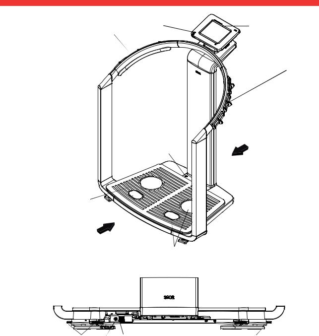
3.1 Controls
1 |
2 |
8
 3
3
 4
4
5
Rear
7 
Front
6
Rear of weighing platform
|
9 |
10 |
11 |
12 |
|
|
|
|
|
No. |
Control |
|
Function |
|
|
|
|
|
|
1 |
|
|
Switches device on: press button briefly |
|
ON/OFF button with LED |
|
Switches device to standby: press button briefly |
|
|
|
|
|
Switches device off: press button and hold |
|
|
|
|
|
|
2 |
Touchscreen display |
|
Central control and display element, can be swiveled 180° to left and right |
|
|
|
|
|
|
10 •
|
|
English |
|
|
|
|
|
No. |
Control |
Function |
|
|
|
|
|
|
|
For connecting a USB memory stick (contained in the scope of delivery) |
|
|
|
for administering the following data: |
|
3 |
|
• creating seca patient files on the device |
|
USB interface |
• loading seca patient files from the seca 115 PC software supplied onto |
|
|
|
|
the USB memory stick; calling up data on the device |
|
|
|
• saving measured results to the USB memory stick |
|
|
|
• reading out log files from the device (administrator function) |
|
|
|
|
|
4 |
Pair of hand electrodes, right |
3 pcs. with finger spacers, for bioimpedance measurement |
|
The patient selects an electrode pair depending on their height |
|
||
|
|
|
|
|
|
|
|
5 |
Spirit level |
Shows whether the device is horizontal |
|
|
|
|
|
6 |
Pair of foot electrodes, right |
For heels and balls of feet, for bioimpedance measurement |
|
|
|
|
|
7 |
Pair of foot electrodes, left |
For heels and balls of feet, for bioimpedance measurement |
|
|
|
|
|
8 |
Pair of hand electrodes, left |
3 pcs. with finger spacers, for bioimpedance measurement |
|
The patient selects an electrode pair depending on their height |
|
||
|
|
|
|
|
|
|
|
9 |
Foot screws, right |
2 pcs, for precise alignment of the device |
|
|
|
|
|
10 |
Power pack connection |
For connecting the power pack |
|
|
|
|
|
11 |
Ethernet interface |
For integrating the device in a PC network |
|
|
|
|
|
12 |
Foot screws, left |
2 pcs, for precise alignment of the device |
|
|
|
|
|
Device overview • 11

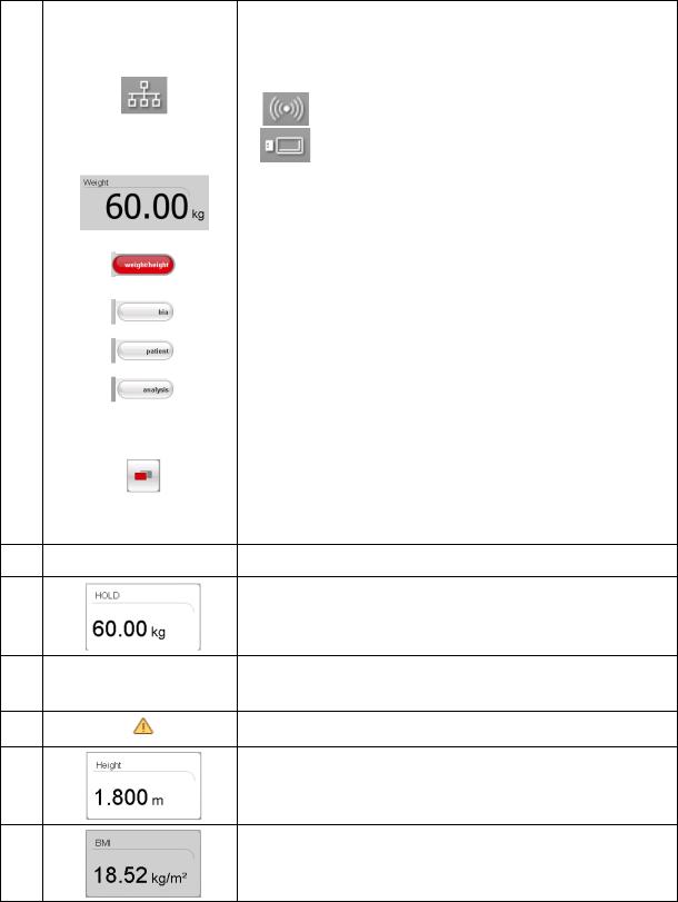
3.2 Symbols in the start display
A B C D E
F
G
H
Q 
P 
O 
I
N
M
J
|
|
L |
K |
|
|
|
|
|
Symbol |
|
Meaning |
|
|
|
|
|
|
Header, remains unchanged in all menu levels and tabs. The following |
|
|
|
data are displayed: |
|
|
|
• patient data |
|
A |
|
- name |
|
|
- weight |
|
|
|
|
- height |
|
|
|
- BMI |
|
|
|
• data connections |
|
|
|
• date/time |
|
|
|
|
|
B |
|
Login symbol: |
|
|
indicates whether the user is logged in to a seca patient database (user |
||
|
|
PIN required) |
|
|
|
|
|
C |
|
Printer symbol: |
|
|
indicates whether the print function of the seca 115 PC software is |
||
|
|
available |
|
|
|
|
|
D |
|
Measuring rod symbol: |
|
|
indicates whether there is a connection to a seca 360° stadiometer |
||
|
|
||
|
|
|
|
12 •
English
|
Symbol |
Meaning |
|
|
Data connection symbol: |
||
|
indicates the current type of connection to the seca patient database (in |
||
|
this case Ethernet connection between PC and seca 115 |
||
E |
Additional possible connection types: |
||
|
|
||
|
• |
seca 360° wireless connection between PC and seca 115 |
|
|
• |
USB memory stick connected to device |
|
|
|
||
F |
Weight display |
||
|
|
||
G |
weight/height tab |
||
Automatically active after device is switched on |
|||
|
For determining weight and height of patient |
||
|
|
||
H |
bia tab |
||
For performing a bioimpedance analysis |
|||
|
|||
|
|
||
I |
patient tab |
||
For assigning the measured results to a seca patient file |
|||
|
|||
|
|
||
J |
evaluation tab |
||
For evaluating measured results and analysis results and for saving data |
|||
|
|||
|
|
||
|
menu changeover button |
||
|
Appears if secondary menu is available |
||
|
• Primary menu: contains the functions commonly used in the current |
||
K |
context |
||
• Secondary menu, contains the following functions: |
|||
|
|||
|
- |
settings |
|
|
- |
||
|
- |
save |
|
L Menu bar with context-dependent buttons and menu changeover button
M |
Hold value display |
Weighing range currently in use:
N 
 • 1: finer divisions of the weight display at a lower capacity
• 2: maximum capacity
O |
Non-verifiable function is active (for verified models only) |
Display of patient's height P • Can be entered manually
• Can be received by a seca 360° stadiometer
Display of patient's body mass index (BMI)
Q Calculated automatically as soon as a weight is available and a height value has been received or entered
Device overview • 13
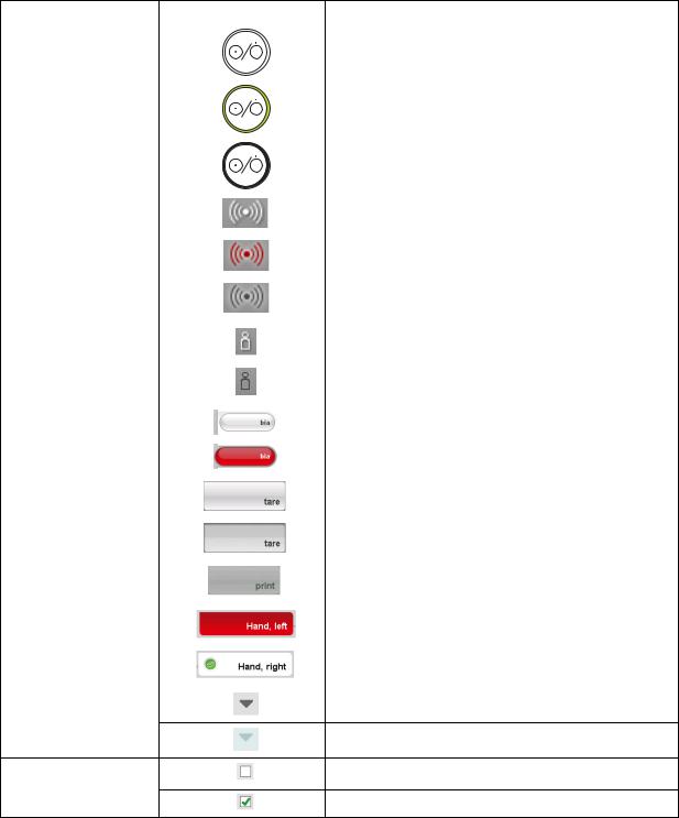
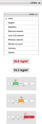
3.3 Color symbols and other controls
|
|
|
|
|
|
Control/display |
Symbol |
Meaning |
|
|
|
|
|
|
|
|
|
LED white: device on |
|
|
|
|
|
|
|
ON/OFF button |
|
LED green: device on standby |
|
|
|
|
|
|
|
|
|
LED off: device off |
|
|
|
|
|
|
|
Data connection |
|
White: connection available |
|
|
|
|
|
|
|
symbol, in this case |
|
|
|
|
|
|
|
|
|
seca 360° wireless link |
|
Red: data being transmitted on the available connection |
|
|
between a PC and |
|
|
|
|
seca 115 |
|
Gray: connection not available |
|
|
|
|
||
|
|
|
|
|
|
Login symbol: log in to a |
|
White: user is logged in |
|
|
|
|
|
|
|
seca patient database |
|
|
|
|
|
Gray: no user logged in |
||
|
|
|
||
|
|
|
|
|
|
|
|
White: tab not selected |
|
|
Tab |
|
|
|
|
|
Red: tab selected |
||
|
|
|
||
|
|
|
|
|
|
|
|
Light gray: function available |
|
|
|
|
|
|
|
Buttons |
|
Gray: button pressed, function selected |
|
|
|
|
|
|
|
|
|
Dark gray: function not available |
|
|
|
|
|
|
|
Electrode indicator (for |
|
Red: contact poor |
|
|
|
|
|
|
|
bioimpedance |
|
|
|
|
|
|
|
|
|
measurement) |
|
Green: contact good |
|
|
|
|
||
|
|
|
|
|
|
|
|
Gray: function available |
|
Drop-down triangles
Light gray: function not available
No tick: function deactivated
Checkboxes
Tick: function activated
14 •
English
Control/display |
Symbol |
Meaning |
|
|
|
|
|
Selected function |
Drop-down menu |
|
|
|
|
|
|
|
Drop-down menu open |
|
|
|
|
|
Red text: value outside normal range |
Text color |
|
|
|
Gray text: value within normal range |
|
|
|
|
|
|
|
|
|
Green: Value within normal range |
Display, evaluation |
|
|
|
Orange: Value slightly elevated |
|
|
|
|
|
|
Red: Value outside normal range |
|
|
|
Device overview • 15

3.4 Menu structure
settings
user
admin
admin PIN
service
System
Default module selection
Unit changeover
Region
Date/time
Ethernet network
seca CLS network
Wireless network
Monitor & sound
Versions
System
Service: primary functions
For authorized service engineers only
Read off calibration counter
Show/hide default module selection before BIA measurement
Activate/deactivate modules for default module selection
Set weight units
Set energy units
Set height unit
Set setup location
Set language
Set date format
Set time format
Set name format
Set name hyphen
Set date
Set time
View current settings
Activate/deactivate DHCP
Set up Ethernet
Enter IP address
Enter port
Activate/deactivate wireless module
Set up wireless group
View wireless devices
Set display brightness
Set volume
Export system log file
Change administrator PIN
Calibrate touchscreen display
Reset admin settings
Change GAL value
Calibrate device
Set the quality check
Update device software
Export/import settings
Enter IP address
Enter netmask
Enter domain name server
Enter default gateway
For authorized service engineers only
16 •

English
3.5 Identification on the device and the type plate
|
|
|
|
|
|
|
|
|
|
|
|
|
|
|
|
|
|
|
|
|
|
|
|
|
|
|
|
|
|
|
|
|
|
|
|
|
|
|
|
|
|
|
|
|
|
|
|
|
|
|
|
|
Text/symbol |
Meaning |
|
|||||||||||||||||||
|
|
|
|
|
|
|
|
|
|
|
|
|
|
|
|
|
|
|
|
|
|
|
|
|
|
|
|
|
|
|
|
Mod |
Model number |
|
|||||||||||||||
|
|
|
|
|
|
|
|
|
|
|
|
|
|
|
|
|
|
|
|
|
|
|
|
|
|
|
|
|
Approval Type |
Type designation of design approval (seca 515 only) |
|
||||||||||||||||||
|
|
|
|
|
|
|
|
|
|
|
|
|
|
|
|
|
|
|
|
|
|
|
|
|
|
|
|
|
|
|
|
|
S/N |
Serial number, consecutive |
|
||||||||||||||
|
|
|
|
|
|
|
|
|
|
|
|
|
|
|
|
|
|
|
|
|
|
|
|
|
|
|
|
|
|
ProdID |
Product identification number, consecutive |
|
|||||||||||||||||
|
|
|
|
|
|
|
|
|
|
|
|
|
|
|
|
|
|
|
|
|
|
|
|
|
|
|
|
|
|
|
|
|
|
|
|
|
|
|
|
|
|
|
|
|
|
|
|
Follow instructions for use |
|
|
|
|
|
|
|
|
|
|
|
|
|
|
|
|
|
|
|
|
|
|
|
|
|
|
|
|
|
|
|
|
|
|
|
|
|
|
|
|
|
|
|
|
|
|
|
|
|
Medical electrical device, type BF |
|
|
|
|
|
|
|
|
|
|
|
|
|
|
|
|
|
|
|
|
|
|
|
|
|
|
|
|
|
|
|
|
|
|
|
|
|
|
|
|
|
|
|
|
|
|
|
|
|
|
|
|
|
|
|
|
|
|
|
|
|
|
|
|
|
|
|
|
|
|
|
|
|
|
|
|
|
|
|
|
|
|
|
|
|
|
|
|
|
|
|
|
|
|
|
|
|
|
|
Insulated device, protection class II |
|
|
|
|
|
|
|
|
|
|
|
|
|
|
|
|
|
|
|
|
|
|
|
|
|
|
|
|
|
|
|
|
|
|
|
|
|
|
|
|
|
|
|
|
|
|
|
|
|
|
|
|
|
|
|
|
|
|
|
|
|
|
|
|
|
|
|
|
|
|
|
|
|
|
|
|
|
|
|
|
|
|
|
|
|
|
|
|
|
|
|
|
|
|
|
|
|
|
|
Device complies with EC standards and directives. |
|
|
|
|
|
|
|
|
|
|
|
|
|
|
|
|
|
|
|
|
|
|
|
|
• M: Conformity label according to Directive 2014/31/EU governing non-automatic weighing |
|
|
|
|
|
|
|
|
|
|
|
|
|
|
|
|
|
|
|
|
|
|
|
|
instruments (verified models) |
|
|
|
|
|
|
|
|
|
M16 |
01230102 |
|
|
|
• 16: (Example: 2016) Year in which the declaration of conformity was completed and the CE |
|
||||||||||
|
|
|
|
|
|
|
|
|
|
|
||||||||||||||
|
|
|
|
|
|
|
|
|
|
|
|
|
|
|
|
|
|
|
|
|
|
|
symbol was applied (verified model) |
|
|
|
|
|
|
|
|
|
|
|
|
|
|
|
|
|
|
|
|
|
|
|
|
|
|
|
|
|
|
|
|
|
|
|
|
|
|
|
|
|
|
|
|
|
|
|
|
|
|
|
|
|
|
|
|
|
|
|
|
|
|
|
|
|
|
|
|
|
|
|
|
|
|
• 0102: Notified body metrology (verified models) |
|
|
|
|
|
|
|
|
|
|
|
|
|
|
|
|
|
|
|
|
|
|
|
|
• 0123: Notified body medical products |
|
|
|
|
|
|
|
|
|
|
|
|
|
|
|
|
|
|
|
|
|
|
|
|
|
|
|
|
|
|
|
|
|
|
|
|
|
|
|
|
|
|
|
|
|
|
|
|
|
Class III scale to Directive 2014/31/EU and OIML R76-1 (verified models) |
|
|
|
|
|
|
|
|
|
|
|
|
|
|
|
|
|
|
|
|
|
|
|
|
|
|
|
|
|
|
|
|
|
|
|
|
|
|
|
|
|
|
|
|
|
|
|
|
|
|
|
|
|
|
|
|
|
|
|
|
|
|
|
|
|
|
|
|
|
|
|
|
|
|
FCC symbol (USA) |
|
|
|
|
|
|
|
|
|
|
|
|
|
|
|
|
|
|
|
|
|
|
|
|
|
|
|
|
|
|
|
FCC ID |
For USA: device license number from the Federal Communications Commission (FCC) |
|
|||||||||||||||||
|
|
|
|
|
|
|
|
|
|
|
|
|
|
|
|
|
|
|
|
|
|
|
|
|
|
|
|
|
|
|
|
|
IC |
For Canada: device license number from Industry Canada |
|
||||||||||||||
|
|
|
|
|
|
|
|
|
|
|
|
|
|
|
|
|
|
|
|
|
|
|
|
|
|
|
|
|
|
|
|
|
|
|
|
|
|
|
|
|
|
|
|
|
|
||||
|
|
12 V |
|
|
|
|
|
|
|
|
|
|
|
|
|
|
|
|
Operate device only with an original seca power pack |
|
||||
|
|
|
|
|
|
|
|
|
|
|
|
|
|
|
|
|
|
|
||||||
|
|
|
|
|
|
|
|
|
|
|
|
|
|
|
|
|
|
|||||||
|
|
min. 1,25 A |
|
|
||||||||||||||||||||
|
|
|
|
|
use compatible |
|
|
|
||||||||||||||||
|
|
|
|
|
seca adapter only |
|
|
|
||||||||||||||||
|
|
|
|
|
|
|
|
|
|
|
|
|
|
|
|
|
|
|
|
|
|
|
|
|
|
|
|
|
|
|
|
|
|
|
|
|
|
|
|
|
|
|
|
|
|
|
|
|
|
|
|
|
|
|
|
|
|
|
|
|
|
|
|
|
|
|
|
|
|
|
|
|
USB interface |
|
|
|
|
|
|
|
|
|
|
|
|
|
|
|
|
|
|
|
|
|
|
|
|
|
|
|
|
|
|
|
|
|
|
|
|
|
|
|
|
|
|
|
|
|
|
|
|
|
Do not dispose of device with household waste |
|
|
|
|
|
|
|
|
|
|
|
|
|
|
|
|
|
|
|
|
|
|
|
|
|
|
|
|
|
|
|
|
|
|
|
|
|
|
|
|
|
|
|
|
|
|
|
|
|
|
|
Device overview • 17
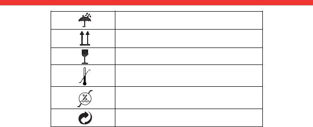
3.6 Identification on the packaging
Protect from wet
Arrows point to top of product
Transport and store upright
Fragile
Do not throw or drop
Permitted min. and max. temperature for transport and storage
Permitted min. and max. humidity for transport and storage
Packaging can be disposed of via recycling programs
18 •
 Loading...