


Variants:
6061321009
6061321619
for seca 606
Service Manual Number:
17-05-01-316-
Valid as of: 01.05.03
Description:
electronic veterinarian scale
Content:
Operation |
17-10-06-293 |
Description display modul |
30-34-00-618 |
Description DMS modul |
30-34-00-645 a |
Description of faults |
30-34-00-588 c |
Calibration (lin.) |
30-34-00-603 |
PC configuration program |
30-34-00-672 b |
cableplan |
08-02-06-022 a |
Replacement |
30-34-00-704 |
Spare parts |
30-34-00-705 |
Manual number: 17-05-01-316-
Brief description of the display module
Introduction
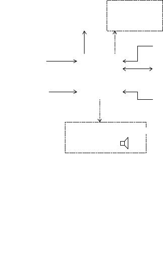
The display modules belong to the family of seca electronic modules and are used to display a weight measured with a suitable module and transferred via the SeSAM bus (Seca’s Serial Autoconfiguring Multicontroller bus). Furthermore, the display modules accommodate the operating elements and can process the weight (hold, tare, etc.).
The following block diagram shows the most important function blocks of the display modules:
|
|
|
Display |
|
B a c klig h tin g |
|||||
|
|
I00.00 |
|
optional |
||||||
|
|
|
|
|
|
|
|
|||
|
|
|
|
|
|
|
|
|
|
|
|
|
|
|
|
|
|
|
|
|
|
|
|
|
|
|
|
|
|
Q uarz |
|
|
|
|
|
|
|
|
|
|
|
|
|
O peration |
|
|
|
|
|
|
|
|
|
|
|
|
|
µ C |
|
|
SeSA M bus |
||||
|
|
|
|
|
|
|
||||
|
|
|
|
|
||||||
|
|
|
|
|
|
|
|
|
|
|
|
|
|
|
|
|
|
|
|
|
|
|
|
|
|
|
|
|
|
|
|
|
Identification |
|
|
|
|
|
Pow er on |
|
|||
|
|
|
|
|
|
|
|
reset |
|
|
|
|
|
|
|
|
|
|
|
|
|
Signal transm itter 
optional
Display
The weight displayed on the LCD is updated approximately every 0.8s. A maximum of five digits as well as a few special characters can be displayed, which can appear as shown below:
Explanation of the special characters:
•The battery symbol is used to alert of the fact that the battery is going flat.
•The plug symbol indicates that the scale is operated on a mains transformer.
•The warning triangle signals that the weight displayed on the scale is not verifiable.
•Hold indicates that the weight display has frozen.
•Tare or Net show that a weight on the scale has been tared out.
•The left and right arrows point to additional explanations next to the display.
•The weight units on the right show in which unit the measured weight is displayed.
Power supply
Power supply is provided via the SeSAM bus.
30-34-00-618 |
1 |
20.04.99 |
|
|
EE/Jensen |
Operation
With the exception of a start button that might be available, the connected buttons can be configured as required for the particular model. These buttons can be pressed just lightly or longer (longer than 1.5s).
If you press another button when switching on the scale, the scale will switch to the verification counter and recalibration mode.
SeSAM bus
The SeSAM bus connects the display modules to the other modules. On this bus the stabilized and non-stablized supply voltages are available. Via a data and a clock pulse line all relevant data is exchanged. A special start line is provided via which the scale can be switched on or the module can signal that it wants to send data.
Identification code
If several display modules are connected, an unmistakable ID code must be assigned to them using soldering jumpers to ensure that the different modules are correctly addressed via the bus.
Backlighting (optional)
Some display modules are equipped with a power supply for LCD backlighting. It can either be lit when the scale is switched on or only when the scale is loaded.
Signal transmitter (optional)
Some display modules are equipped with a signal transmitter. A piezo diaphragm is used which is controlled with a 4 kHz square-wave signal.
Fault handling
If faults occur, the SeSAM bus initiates a fault message with the relevant fault code. Furthermore, each fault message includes the number of the module type on which the fault has occurred and a code which indicates how long the message is to stay on display and which displays are to be suppressed.
The display module displays its own fault messges on its LCD. Module type (for the display module = 3) and fault number are output. In addition, the fault messages that other modules have transferred to the SeSAM bus are displayed.
The following fault messages are implemented:
14Fault in the kg value calculation
15Recalibration fault
30 General bus fault
32Command buffer full
33More than 8 slaves detected
50Other fault
51Menu fault
Time base
From the quartz’s 4.19MHz a time base is derived which controls all timed processes in the scale. These are, for instance, various timeouts.
Recalibration
In order to compensate for linear measuring errors of the scale, which can, for instance, occur as a result of the different forces of gravity at different geographical points, the module has a recalibration
30-34-00-618 |
2 |
20.04.99 |
|
|
EE/Jensen |
function. To initiate the function, another button must be pressed when the scale is started. The verification counter is then displayed which is incremented whenever the scale is recalibrated. It enables the user to check whether the scale was manipulated. If, within five seconds, the button is pressed longer than 1.5 s, the scale switches to recalibration mode. The scale now measures the zeropoint and waits to be loaded with at least ¼ of the maximum load. By briefly pressing the button the weight displayed can be decremented or incremented in steps of 10g until the weight of the load placed on the scale is reached. The direction can be changed by pressing the button longer. To stop recalibration the button must be pressed longer than 5s. The scale can be switched off any time using the on/off button or by not actuating it for a while, thus aborting recalibration.
Optional functions
The functions “Tare“, “Hold“, “Autohold“ and “Replace weight in repeat measurements” and various menu functions can be implemented via a program on the EEPROM (on the weight measuring
module). The functions are explained below:
Tare:
The tare function can be assigned to a button by the EEPROM program. If the button is pressed, the weight is tared out as soon as the display has settled, if it is within the permissible range. Pressing the button again alternatively switches the tare function off or causes the weight to be tared out again.
Hold and Autohold:
If the hold function is assigned to a button by means of the EEPROM, the weight reading is held on display when the button is pressed as soon as the value has stabilized. Alternatively, the hold function can be automated so that the weight will always be frozen when it has exceeded a certain threshold and is stable.
The hold function is switched off after expiry of a predetermined time or by pressing the button again. In addition the scale can be configured so that the hold function will be deactivated when the scale is relieved, when the scale is relieved and then loaded again and / or when the load on the scale changes significantly.
Replace weight in repeat measurements:
The scale can be configured so that the weight last displayed is displayed again in a measurement when the scale detects that it has been loaded with almost the same weight.
Menu functions:
Not all the functions listed below can be activated on the same scale.
When the menu button is pressed long enough, the scale switches to the setting mode. Here, damping and weight display settings can be made.
When the button is pressed briefly, the scale switches to function mode. The following functions are possible:
•BMI: From weight and height the body mass index is calculated using the following formula
BMI = weight[kg]/ length[m]2 |
BMI = weight [ kg] / height [ m] 2. |
|
• IDE: The deviation from |
the |
ideal weight calculated using the formula |
09, × (length[cm] - 100) |
0.9 (height[ cm] - 100) is displayed. |
|
•UL: When a limit weight is overshot or undershot an acoustic signal is generated.
•DIFF: The difference to a second weight is output. The second weight can have been measured using the autohold function, entered manually or stored when the difference function was last called.
Technical data
Supply voltage: |
2.7V - 3V and 2.7V - 15V (via SeSAM bus) |
|
Supply current: |
typ. 0.5mA + power supply for backlighting (typ. 100mA) |
|
Quiescent current: |
typ. 2µA |
|
Operating temperature: |
approx. 0° C to 50° C |
|
30-34-00-618 |
3 |
20.04.99 |
|
|
EE/Jensen |
Storage temperature: |
-10° C to 60° C |
|
Dimensions: |
74mm x 50mm x 23mm |
small display |
|
100mm x 84mm x 21mm |
large display |
|
67mm x 38mm x 23mm |
backlit display |
30-34-00-618 |
4 |
20.04.99 |
|
|
EE/Jensen |

Service manual |
Description of the electronics |
Brief description of the DMS module
Introduction
The DMS modules are used to determine weights using a load cell with strain gauges. The DMS low end module also accommodates the display and the operating unit. To allow the modules to be adapted to different scales, an EEPROM is integrated which is used to configure the module. A connection to the SeSAM bus (Seca’s Serial Autoconfiguring Multicontroller bus) is provided via which the scale can be calibrated and additional modules can be connected.
Display
Load cell |
A/D Converter |
I0000. |
|
|
Operation |
||
|
|
|
|
|
Voltage |
|
EEPROM |
|
|
|
|
|
control |
|
Quartz |
|
|
|
|
|
Temperature |
µC |
SeSAM Bus |
|
measurement |
|
|
|
|
|
|
|
|
|
Power On |
|
Voltage |
|
Reset |
|
|
|
|
|
measurement |
Voltage |
|
|
|
|
|
|
|
control |
|
Mains connection
Battery/rechargeable batteries
Weight measurement
The DMS modules use load cells with strain gauges in a double bridge circuit as sensors.
The entire analog part runs on its own supply voltage. This voltage can be switched by the µC to 3V, 5V or 10V. This voltage is also supplied to the load cells. At full load, they deliver a bridge output voltage of 2mV/V.
This voltage is measured by a dual slope a/d converter. The DMS ext module can evaluate up to four load cells which are multiplexed accordingly. Only one load cell can be connected to the other types of DMS modules.
The conversion time is selected so that a new measured value is available every 0.1 s.
The resolution of the a/d converter is 0.05 µV/V. If several load cells are connected, keep in mind that the resolution relates to the mean output signal of all the load cells connected.
When these measured values are within the expected range, they are converted into a weight value using a third order polynomial. In order to increase accuracy, eight measured values are used to calculate the weight to be displayed.
The first value obtained after switch-on is used as the zero point. If the values obtained later on do not deviate strongly from this value, the zero point is corrected in order to compensate for possible drifts. (Please also refer to temperature measurement.)
31.03.2000 /Jensen |
1 |
34-34-00-645 Index a |

Service manual |
Description of the electronics |
Display (DMS low-end module only)
Whenever eight new measured values are available, i.e. approx. every 0.8 s, the weight is displayed. The display is an LCD which is controlled by duplex operation. A maximum of five digits as well as a few special characters can be displayed.
Explanation of the special characters:
•The battery symbol is used to alert of the fact that the battery is going flat.
•Hold indicates that the weight display has frozen.
•Tare or Net indicate that a weight on the scale has been tared off.
•The left arrow indicates if additional explanations are given next to the display.
•The weight units on the right show the unit in which the measured weight is displayed.
Temperature measurement
In order to compensate for the load cell’s temperature drift, the temperature is measured regularly and the measured value is adjusted accordingly.
To perform this measurement, a capacitor is charged every 2 seconds alternately via a reference resistor and an NTC with a linearization resistor connected in parallel. The time until the capacitor has reached a specific voltage is measured. The temperature is calculated from the ratio of the two times.
To reduce measured value fluctuations, a mean value of 16 temperature values is always formed. The fluctuation then amounts to approx ± 0.2°C.
The difference between the current temperature and the temperature measured when the last zero point was obtained is used to determine a projected zero point. To do so, one assumes that the weight change per °C is constant. The weight value is then corrected in accordance with the zero point calculated and in accordance with the difference to the temperature measured when the scale was calibrated. A linear and a square term are used for this purpose.
Power supply
Power supply is provided by AA size batteries (batteries or rechargeable batteries) and a plug-in power supply unit. The batteries pass the voltage via reverse voltage protection diodes to a 3V in-phase regulator. A coil which suppresses interference and a buffer capacitor come next. This 3 V supply voltage is supplied to the digital part of the circuit.
Another in-phase regulator generates the voltage for the analog part. The µC can set this regulator to 3V, 5V or 10V.
In order to operate the module on rechargeable batteries a recharging circuit can be connected. This circuit charges the rechargeable batteries at a constant current when a power supply unit is connected. When the supply voltage is applied, a power-on reset is initiated at the µC via an RC element.
To monitor the condition of the batteries, their voltage is measured every 2s. For this purpose, a 2.2 V reference voltage is integrated upwards and the time until the voltage has reached approx. 9% of the supply voltage is measured. Afterwards, a downwards integration is made from 2.2V to the threshold. From these two results, a measured value for the voltage is calculated. If the voltage drops below a certain limit, the user is alerted by the battery symbol in the LCD. If the next threshold is undershot, „bAtt“ is displayed and weighing is no longer possible.
Operation (DMS low-end module only, with the exception of vibration-sensitive switch and platform switch)
Four buttons are provided; one is used to switch the module on and off, the others can be programmed as required. These three buttons can be pressed just lightly or longer (longer than 1.5s), so that six events are available. The actions tare, hold and unit switch-over can be assigned to them.
If you press another button when switching on the scale, the scale will switch to the calibration counter and recalibration mode.
Instead of the normal start button a piezo diaphragm can be soldered to the PI connection. If the piezo diaphragm registers a vibration, a transistor switches and generates an interrupt signal which causes the µC to start.
If the start button is directly connected to this interrupt input, a button is obtained which is only active when the scale is switched off. It can be fitted under the platform, for instance, so that the scale is started by briefly stepping on it.
31.03.2000 /Jensen |
2 |
34-34-00-645 Index a |

Service manual |
Description of the electronics |
Programming
The DMS modules are equipped with an EEPROM which is controlled via the I²C bus protocol. On this EEPROM all parameters are stored that can be used to influence the program sequence. For example the way the weight is displayed or the allocation of buttons. It also stores the coefficients for determining the weight and data for temperature compensation, e.g. the factors for the polynomial.
Furthermore, the scale can store values to be retrieved when the scale is switched on the next time, e.g. the weight unit used last.
In order to avoid errors, the EEPROM contents are divided into blocks which are monitored by cyclic redundancy checks. The hamming distance is 4 so that single errors can be corrected and double errors are certainly detected. In addition, values which are recalculated when the scale is in operation can be replaced by default values if an error is detected that cannot be remedied.
Serial bus
To allow the scale to be calibrated and additional modules, such as additional displays, to be connected, the DMS modules are equipped with an interface to the SeSAM bus.
On this bus the stabilized and non-stabilized supply voltages are available. Via a data and a clock pulse line all relevant data is transmitted to other modules. A special start line is provided via which the scale can be switched on or other modules can signal that they want to send data.
Both data and start line are open collectors so that they can be switched to low by all modules. For further details on the bus, please refer to the relevant documentation.
Fault handling
If faults occur, the SeSAM bus initiates a fault message with the relevant fault code. Furthermore, each fault message includes the number of the module type on which the fault has occurred and a code which indicates how long the message is to stay on display and which displays are to be suppressed.
The DMS low end module displays its own fault messages on its LCD. Module type (0 for the low-end module) and fault number are displayed. The other DMS modules only transfer fault messages to the bus (module type = 1).
The following fault messages are implemented:
10 |
20 bit counter overflow |
|
|
11 |
Counts outside the permissible range |
|
|
12 |
Switch-on zero point outside the permissible range |
|
|
13 |
Zero follow-up outside the permissible range |
|
|
14 |
Fault in the kg value calculation |
|
|
15 |
Recalibration fault |
|
|
20 |
Battery voltage too low |
|
|
21 |
Fault in battery voltage measurement |
|
|
22 |
Fault in temperature measurement |
|
|
23 |
Temperature range exceeded ( < 0°C or > 50°C) |
|
|
30 |
General bus fault |
|
|
32 |
Command buffer full |
|
|
33 |
More than 8 slaves detected |
|
|
40 |
EEPROM fault |
|
|
41 |
Incorrect EEPROM access |
|
|
50 |
Other fault |
|
|
Time base
From the quartz’s 4.19MHz a time base is derived which controls all timed processes in the scale. These are, for instance, various timeouts and the on-time.
After expiry of the on-time, the supply voltage for the analog part, for voltage measurement and for the EEPROM is switched off. The LCD is switched off, all ports are set to zero-signal level and the quartz is stopped.
31.03.2000 /Jensen |
3 |
34-34-00-645 Index a |
 Loading...