


674
Variants:
6741321108
6741321378
6757021008
6757021198
6757021228
6757021248
6757021288
Service Manual
for seca 674, 675 NEC2
Service Manual Number
17-05-01-374-
Description:
Electronic platform scales with high load-bearing capacity and castors for transport
When servicing or repairing seca devices according to this service manual, always take note of the
instruction manual of th e product. To download the latest version of the ins t ruction manual and EMC
Recommendation go to
www.seca.com
.
Valid as of: 01.02.2013
Contents:
Service description electronic 30-34-00-812 c
Cableplan
Replacement
Spare parts
Spare parts
Spare parts
Spare parts
Spare parts 675 7021228
Spare parts
Spare parts 675 7021288
Spare parts drawing Frame 30-34-00-840
Spare parts drawing display
EMC Recommendation
08-02-06-058 a
30-34-00-859
674 1321108
674 1321378
675 7021008
675 7021198
675 7021248
30-34-00-846
30-34-00-519
Instruction manual 656
Instruction manual 657
Manual number: 17-05-01-374-
17-10-06-383
17-10-07-608

General information seca
Electronics (NEC2) Service
Instructions
ODEL
M
[374|376|378|703|704|264|274|284|285|634|635|644|645|
656|657|664|665|675|676|677|684|685|954|955|957|959|
963]
14.11.12/RLEU/ARI/MRE 1/40 30-34-00-812c

General information seca
Contents
1 General Information
[374|376|378|634|635|644|645|656|657|664|665|674|675|676|677|684|685|70
3|704|264|274|284|285|954|957|959|963]...................................................... 5
1.1 Type Plates
[374|376|378|634|635|644|645|656|657|664|665|674|675|676|677|684|685|70
3|704|264|274|284|285|954|957|959|963]....................................................... 5
1.2 Design and Function of the Scale Part
[374|376|378|703|704|634|635|644|645|656|657|664|665|674|675|
676|677|684|685|264|274|284|285|954|957|959|963]..................................... 6
1.2.1 Design
[374|376|378|703|704634|635|644|645|656|657|664|665|674|675|676|677|6
84|685|284|285] .......................................................................................... 6
1.2.2 Function
[374|376|378|703|704634|635|644|645|656|657|664|665|674|675|
676|677|684|685|284|285]........................................................................... 6
1.3 Design and Function of the Head Slider [264|274|284|285].................7
2 Maintenance
[374|376|378|703|704|634|635|644|645|656|657|664|665|674|675|676|677|68
4|685|264|274|284|285|954|957|959|963]...................................................... 8
2.1 Adjustment of Scales
[374|376|378|703|704|634|635|644|645|656|657|664|665|674|675|
676|677|684|685|264|274|284|285|954|957|959|963]................................... 10
2.1.1
General[374|376|378|703|704|634|635|644|645|656|657|664|665|
674|675|676|677|684|685|264|274|284|285|954|957|959|963].................. 10
2.1.2 Calibration Counter / Number of Adjustments
[374|376|378|703|704|634|635|644|645|656|657|664|665|674|675|676|677|
684|685||264|274|284|285|954|957|959|963]............................................11
2.1.3 Adjustment Mode and Displaying the Calibration Counter
Contents
[374|376|378|703|704|634|635|644|645|656|657|664|665|674|675|676|677|
684|685|954|957|959|963]......................................................................... 11
2.1.4 Adjustment Mode and Displaying the Calibration Counter
Contents [284|285]....................................................................................12
2.1.5 Placing Adjustment Weights on the Scale .................................. 12
14.11.12/RLEU/ARI/MRE 2/40 30-34-00-812c

General information seca
2.1.6 Example: Adjusting a Scale with 100g Graduations
[703|704|284|285|634|635|644|645|656|657|664|665|675|676|677 |684|685]
13
2.1.7 Example: Adjusting a Baby Scale with 10g Graduations [374|376]
13
2.1.8 Overview of Adjusting a Scale with 100g Graduations [703|704] 14
2.1.9 Overview of Adjusting a Baby Scale with 10g Graduations
[374|376|378] ............................................................................................ 16
2.2 Adjusting the Head Slider [284|285]................................................... 17
2.2.1 Displaying the Gravity Factor
[374|376|378|703|704|634|635|644|645|656|657|664|665|674|675|676|677|
684|685|954|957|959|963]......................................................................... 17
2.3 Setting the Gravity Factor
[374|703|634|644|656|664|674|676|684|284|954]:........................................ 18
2.3.1 Example for Gravity Factor Setting
[374|703|634|644|656|664|674|676|684|284|954]..................................... 19
2.3.2 Summary of a Typical Gravity Factor Setting Sequence [374|703].
19
3 Errors
[374|376|378|703|704|634|635|644|645|656|657|664|665|674|675|676|677|68
4|685|954|957|959|963]................................................................................ 21
3.1 Error Symptoms for Scale
[374|376|378|703|704|634|635|644|645|656|657|664|665|674|675|
676|677|684|685|954|957|959|963] .............................................................. 21
3.2 Error Symptoms for Head Slider [264|274|284|285]........................... 22
3.3 Radio Error Symptoms
[374|376|378|703|704|284|285|634|635|644|645|656|657|664|665|
674|675|676|677|684|685|954|957|959|963]................................................. 23
3.4 Scale Error Messages
[374|376|378|703|704|284|285|634|635|644|645|656|657|664|665|
674|675|676|677|684|685|954|957|959|963]................................................. 24
3.5 Head Slider Error Messages [264|274|284|285] ................................ 25
3.6 Radio Error Message
[374|376|378|703|704|284|285|634|635|644|645|656|657|664|665|
674|675|676|677|684|685|954|957|959|963]................................................. 26
14.11.12/RLEU/ARI/MRE 3/40 30-34-00-812c

General information seca
4 Measurements
[374|376|378|703|704|284|285|634|635|644|645|656|657|664|665|674|675|67
6|677|684|685|954|957|959|963].................................................................. 27
4.1 Supply Voltage
[374|376|378|703|704|284|285|634|635|644|645|656|657|664|665|674|675|67
6|677|684|685|954|957|959|963] .................................................................. 27
4.2 Load Cell
[374|376|378|703|704|284|285|634|635|644|645|656|657|664|665|674|675|67
6|677|684|685|954|957|959|963] .................................................................. 27
4.2.1 Measurement Using a Multimeter
[374|376|378|703|704|284|285|634|635|644|645|656|657|664|665|674|675|
676|677|684|685|954|957|959|963]........................................................... 27
5 Software intended Purpose.......................................................................... 30
5.1 Installation and Start .......................................................................... 30
5.2 Updating the Radio Module Software.................................................31
5.3 Set-up Process .................................................................................. 32
5.4 Updating the Radio Module Software.................................................33
5.5 Technical Requirements for Updating................................................34
5.6 Updating the Wireless Printer Software .............................................34
5.7 Updating Old Printers......................................................................... 35
5.8 Problems with Updating..................................................................... 35
Appendixes....................................................................................................... 36
14.11.12/RLEU/ARI/MRE 4/40 30-34-00-812c
General information seca
1 General Information
[
374|376|378|634|635|644|645|656|657|664|665|674|675|676|677
|684|685|703|704|264|274|284|285|954|957|959|963
These service instructions are intended for specialist staff responsible for
maintenance and repair of the devices. These persons must be familiar with all
the relevant electro-technical regulations and must adhere to them any time.
These instructions are not suitable for users without specialist knowledge.
These instructions describe how to service the devices
[374|376|378|634|635|644|645|656|657|664|665|674|675|676|677|684|685|703|
704|264|274|284|285|954|957|959|963]equipped with NEC2 electronic modules.
The device types for which these instructions apply are listed in the section
headings. There are some identical models with NEC1 electronic modules.
These instructions are not valid for those types.
What is the structure of this document and how should you read it? Section 1
provides a short overview of the most important points for service. We
recommend you should read it completely. Section 2 deals with the
maintenance of the devices, i.e. work that may have to be carried out more
frequently. This section can be read as and when required. Troubleshooting is
covered in section 4, where you find detailed descriptions of various
measurements intended to identify specific errors. Starting point for
troubleshooting is section 3, which includes an overview of error descriptions
and the inspection steps required to identify them.
]
1.1 Type Plates
[374|376|378|634|635|644|645|656|657|664|665|674|675|676|677|684|685|703|
704|264|274|284|285|954|957|959|963]
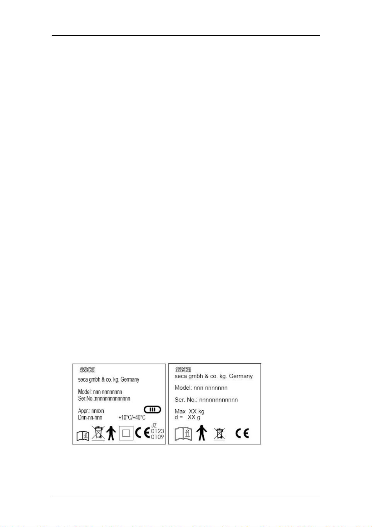
To enable you to identify the device, information about the model and serial
number is found on the underside or on the frame of the device (see Note down
this information so that you have it on hand in case you need to contact us for
queries or spare parts orders.
Figgure 1: Typeplate (left approved, right non approved)
14.11.12/RLEU/ARI/MRE 5/40 30-34-00-812c
General information seca
1.2 Design and Function of the Scale Part
[374|376|378|703|704|634|635|644|645|656|657|664|665|674|675|
676|677|684|685|264|274|284|285|954|957|959|963]
1.2.1 Design
[374|376|378|703|704634|635|644|645|656|657|664|665|674|675|6
76|677|684|685|284|285]
The scale consists of the following main parts: the frame with up to four load
cells, a display unit, a key panel and a power supply unit.
1.2.2 Function
[374|376|378|703|704634|635|644|645|656|657|664|665|674|675|
676|677|684|685|284|285]
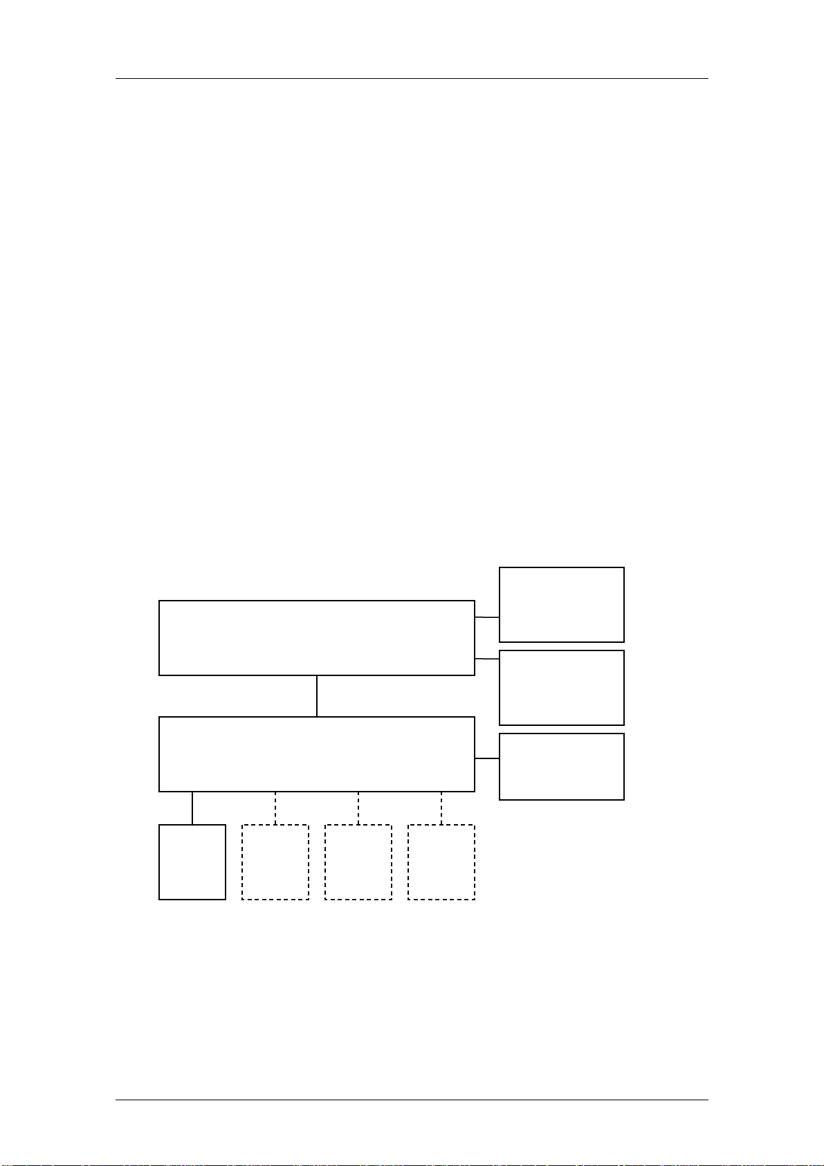
The action of a force causes elastic deformation of the load cell. A
corresponding analog signal is supplied, which changes linearly with the force
applied. This signal is measured and evaluated by the scale electronics and
displayed as a weight value. shows the functional diagram for scales with
separated modules for determining and displaying the weight.
Radio module
NEC2 Display module
08-06-18-170 oder -195
NEC2 DMS Module (Weight measurement)
Load
cell
ISIS BUS (Modular cable)
08-06-18-156
Load
cell
Load
cell
Load
cell
08-06-18-172
Keyboard
DC Supply
Figure 1: Functional diagram [704|284|285|634|635|644|645|656|657|664|665|675|677|684|685]
14.11.12/RLEU/ARI/MRE 6/40 30-34-00-812c
General information seca
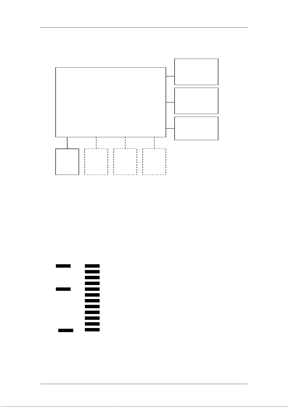
NEC2 Compact module
(Weight measurement and display)
08-06-18-167 oder -163
Figure 3: Functional diagram [374|376|378|703|954|957|959|963]
Load
cell
Load
cell
Load
cell
Load
cell
Radio module
08-06-18-172
Keyboard
DC Supply
1.3 Design and Function of the Head Slider [264|274|284|285]
The head slider uses the measuring method of visual reading off from the insert
scale. Absolute and relative graduation marks are scanned to determine
lengths. Once the slider has moved more than two absolute marks, the absolute
position can be determined and a length is output.
Figure 4: Absolute (left) and relative graduation marks (right) [264|274|284|285]
14.11.12/RLEU/ARI/MRE 7/40 30-34-00-812c

Maintenance seca
2 Maintenance
[374|376|378|703|704|634|635|644|645|656|657|664|665|674|675
|676|677|684|685|264|274|284|285|954|957|959|963]
The following section provides an overview of all maintenance jobs which can
be carried out.
To call up the Service Menu, start the scale while pressing another key at the
same time. This causes the content of the calibration counter (i.e. the number of
adjustment operations carried out so far) to be displayed for 24 seconds
(flashing). While the calibration count is displayed, a key must be kept pressed
(for more than 1.5 seconds); the scale then automatically displays the software
identification number and the check digit.
Keypress (any key) and START key simultaneously
- Calibration counter [see 2.1.2]
- Long keypress (any key)
Automatic display for 6 seconds
- XX.YY (software identification)
Then automatic display for 6 seconds
- XXXX (check digit)
Then automatic display
- CAL [see 2.1.5]
Long keypress (any key)
o DEC
Long keypress (any key)
o INC
Short keypress (any key)
- GAL [see1.3]
Long keypress (any key)
o XXXXX (gravity factor)
Short keypress (any key)
- INFO
14.11.12/RLEU/ARI/MRE 8/40 30-34-00-812c

Maintenance seca
Long keypress (any key)
o No: X (module number)
Long keypress (any key)
o XXX.XX (firmware version, e.g. 290.07)
- End
Software identification and check digit:
The existing seca firmware version number is retained and can be called up.
Firmware software identification
Each and every firmware is given its own software identification number.
This software identification number is composed of a version number for the
program part that is subject to verification and a version number for the program
part that is not subject to verification.
Example: 01.08 01 - subject to verification
08 - not subject to verification
Whenever the firmware is changed, the version number for the program part
that is not subject to verification is increased. This is done by analogy with the
firmware index.
When a program part is changed that is subject to verification, the version
number for the program part that is subject to verification is also increased.
Software identification of the device
The overall version number of the program parts which are subject to
verification is the total of the version numbers (subject to verification) of the
individual hardware modules.
The overall version number of the program parts which are not subject to
verification is the total of the version numbers (not subject to verification) of the
individual hardware modules.
14.11.12/RLEU/ARI/MRE 9/40 30-34-00-812c

Maintenance seca
Firmware check digit
Every firmware is given its own check digit.
Device check digit
The overall check digit for the device is the total of the individual check digits.
Representation on display
Hardware module
Firmware version with index / internal seca value
PTB version number
PTB check digit
Weight module
290.08
01.08
1A47
M704
290.08 / 290.08
02.16
348E
Display
290.08
01.08
1A47
Compact
290.08
01.08
1A47
M703
290.08
01.08
1A47
Weight module
290.08
01.08
1A47
Extended display
M285
290.08 / 298.08
02.16
5CAD
2.1 Adjustment of Scales
[374|376|378|703|704|634|635|644|645|656|657|664|665|674|675|
676|677|684|685|264|274|284|285|954|957|959|963]
298.08
01.08
4266
2.1.1 General[374|376|378|703|704|634|635|644|645|656|657|664|
665|674|675|676|677|684|685|264|274|284|285|954|957|959|963]
To compensate for linear measuring deviations, which occur e.g. as a result of
gravity variations in different gravity zones, the scale offers an adjustment
feature. This adjustment must also be carried out whenever the load cell is
replaced.
14.11.12/RLEU/ARI/MRE 10/40 30-34-00-812c

Maintenance seca
seca scales with modular NEC-G2 electronics are fitted with a softwarecontrolled adjustment device that is controlled using the existing operating
elements. When developing the adjustment device, special attention was paid
to the following requirements:
It must be possible to readjust scales without any additional external
equipment/tools.
The readjustment device must be admissible for verification.
It must be possible to readjust the scales without calibrated test weights.
The readjustment device must be protected against inadvertent use.
Scale adjustment can be carried out manually as described in section 0” or
using seca serva 2.0. Manual adjustment will not correct any corner errors.
2.1.2 Calibration Counter / Number of Adjustments
[374|376|378|703|704|634|635|644|645|656|657|664|665|674|675|6
76|677|684|685||264|274|284|285|954|957|959|963]
Scales fitted with the new, modular electronics are equipped with a calibration
counter allowing a software adjustment to be carried out in accordance with the
requirements for verified scales. Each completed adjustment procedure is
registered by the calibration counter, i.e. the number is automatically
incremented by 1. Non-approved scales are also fitted with a counter which
counts the number of adjustments.
2.1.3 Adjustment Mode and Displaying the Calibration Counter
Contents
[374|376|378|703|704|634|635|644|645|656|657|664|665|674|675|6
76|677|684|685|954|957|959|963]
To begin readjustment or to display the calibration counter contents, start the
scale while pressing another key at the same time. The contents of the
calibration counter (i.e. the number of adjustment procedures carried out so far)
are then displayed for 18 seconds (flashing).
While the calibration count is displayed, a key must be kept pressed (for more
than 1.5 seconds) to switch the scale to adjustment mode.
14.11.12/RLEU/ARI/MRE 11/40 30-34-00-812c
Maintenance seca
2.1.4 Adjustment Mode and Displaying the Calibration Counter
Contents [284|285]
To begin readjustment or to display the calibration counter contents, start the
scale and press another key while the display shows seca. The contents of the
calibration counter (i.e. the number of adjustment procedures carried out so far)
are then displayed for 18 seconds (flashing).
While the calibration count is displayed, a key must be kept pressed (for more
than 1.5 seconds) to switch the scale to adjustment mode.
2.1.5 Placing Adjustment Weights on the Scale
[374|376|378|703|704|634|635|644|645|656|657|664|665|674|675|676|677|684|
685|954|957|959|963]
Once you have switched to adjustment mode as described in section 2.1.3 or
2.1.4, the display shows the text “CAL”. By pressing any key except for the start
key for more than 1.5 seconds, the actual readjustment mode is activated. The
display reads "dec". The weight value currently measured then appears. The
scale is in decrementing state. To switch over from decrementing to
incrementing mode and vice versa press a key for more than 1.5 seconds with a
test weight placed on the scale. The display will read “dec” or “inc” accordingly.
The test weight is at least 25% of the max. load of the scale (we recommend
approx. 66-75%).
Adjustment can now be completed by pressing a key until the display shows
“Sto”. The scale computes and stores a new linearity coefficient and switches
off automatically. Your scale is now adjusted. Remove the test weight.
Note:
Timeout control is not active for the phase of placing and confirming the test weight.
To minimize adjustment errors, readjustment can only be carried out using a test
weight above 25 % and below 100 % of the max. load. Otherwise the error “Er:x:15”
will be displayed.
14.11.12/RLEU/ARI/MRE 12/40 30-34-00-812c

Maintenance seca
2.1.6 Example: Adjusting a Scale with 100g Graduations
[703|704|284|285|634|635|644|645|656|657|664|665|675|676|677
|684|685]
The selected test weight is 200 kg.
The current weight shown on the display is 199.7 kg (max. deviation of 300 g).
In this example, you must switch the scale to incrementing mode to carry out
readjustment. When the tare/hold key has been pressed (for more than 1.5
seconds), "inc" starts flashing.
Now increase the value by the first 10 g (by briefly pressing the tare/hold key).
After this has been repeated x times, the value 200.0 (rounded!) appears on the
display although the internal measured value still is 199.95 kg (not rounded!).
To correct this rounding error, increment the value five times by 10 g to obtain
exactly 200.00 as the calculated value.
Complete the readjustment procedure as described in section 2.1.5.
2.1.7 Example: Adjusting a Baby Scale with 10g Graduations
[374|376]
The selected test weight is 15 kg. The current weight shown on the display is
14.970 kg (max. deviation of 30 g).
In this example, you must switch the scale to incrementing mode to carry out
readjustment. When the tare/hold key has been pressed (for more than 1.5
seconds), "inc" starts flashing.
Now increase the value by the first 1 g (by briefly pressing the tare/hold key).
Each alteration is shown on the display.
Complete the readjustment procedure as described in section 2.1.5.
14.11.12/RLEU/ARI/MRE 13/40 30-34-00-812c
Maintenance seca
A
2.1.8 Overview of Adjusting a Scale with 100g Graduations
[703|704
]
Action carried out by the user
The scale is switched off. No values or characters on the display.
Press the tare/hold key and keep it
pressed while simultaneously pressing
the start key.
Release both keys. The contents of the calibration counter
Press the tare/hold key for more than
1.5seconds within the next 18seconds.
18 seconds have passed and no key has
been pressed.
Result
The contents of the calibration counter
flash on the display for 18 seconds.
flash on the display for 18 seconds.
The system switches to adjustment
selection mode and “CAL” flashes on the
display.
The scale switches off.
Press the tare/hold key for more than 1.5
seconds.
Place the test weight on the scale. The measured weight of the test weight
Decide whether to decrement or to
increment:
Incrementing:
Press the tare/hold key for more than 1.5
seconds.
Decrementing
scale already is in dec mode.
Decrementing or incrementing:
gain briefly press the tare/hold key (for
: No action required as the
"dec" appears on the display (flashing)
and then the current weight (0.0 - also
flashing).
appears on the display (flashing).
Incrementing mode is activated; "inc"
appears on the display.
No output on the display.
The measured weight is decremented or
incremented by 10 g. Please remember
that pressing the key does not always
14.11.12/RLEU/ARI/MRE 14/40 30-34-00-812c
Maintenance seca
less than 1.5 seconds). change the value on the display due to
the low display resolution. Only the
rounded value is output.
Repeat this step until the measured
weight matches the test weight (format:
xxx.0 kg).
To correct this rounding error, decrement
or increment the value five times by 10 g.
Press the tare/hold key until the display
shows “Sto”.
The display indicates the test weight
(format: xxx.0 kg).
The display indicates the exact test
weight (format: xxx.0 kg).
The display reads “Sto” and the scale
switches off automatically.
14.11.12/RLEU/ARI/MRE 15/40 30-34-00-812c
Maintenance seca
2.1.9 Overview of Adjusting a Baby Scale with 10g Graduations
[374|376|378]
Action carried out by the user
The scale is switched off. No values or characters on the display.
Press the tare/hold key and keep it
pressed while simultaneously pressing
the start key.
Release both keys. The contents of the calibration counter
Press the tare/hold key for more than 1.5
seconds.
18 seconds have passed and no key has
been pressed.
Result
The contents of the calibration counter
flash on the display for 18 seconds.
flash on the display for 18 seconds.
The system switches to adjustment
selection mode and “CAL” flashes on the
display.
The scale switches off.
Press the tare/hold key for more than 1.5
seconds.
Place the test weight on the scale. The measured weight of the test weight
Decide whether to decrement or to
increment:
Incrementing:
Press the tare/hold key for more than 1.5
seconds.
Decrementing: No action required as the
scale already is in dec mode.
Decrementing or incrementing: The measured weight is decremented or
"dec" appears on the display (flashing)
and then the current weight (0.000 - also
flashing).
appears on the display (flashing).
Incrementing mode is activated; "inc"
appears on the display.
No output on the display.
14.11.12/RLEU/ARI/MRE 16/40 30-34-00-812c
Maintenance seca
A
gain briefly press the tare/hold key (for
less than 1.5 seconds).
Repeat this step until the measured
weight matches the test weight (format:
xx.000 kg).
Press the tare/hold key until the display
shows “Sto”.
incremented by 1 g.
The display indicates the test weight
(format: xx.000 kg).
The display reads “Sto” and the scale
switches off automatically.
2.2 Adjusting the Head Slider [284|285]
The head slider electronics must be readjusted whenever the electronics are
replaced. Please refer to the instructions in the operating manual.
2.2.1 Displaying the Gravity Factor
[374|376|378|703|704|634|635|644|645|656|657|664|665|674|675|6
76|677|684|685|954|957|959|963]
To view the gravity factor, the scale must first be switched to adjustment mode
(see section 2.1.3 or 2.1.4).
As soon as the text “CAL” is displayed, press a key briefly (less than 1.5
seconds).
The display shows “GAL”.
Pressing a key for more than 1.5 seconds displays the gravity factor set. The
gravity factor is shown in mm/s².
The scale switches off again automatically after 24 seconds.
Note [376|378|704|285]:
On verified scales, the gravity factor can only be displayed as long as the calibration
count is 1.
14.11.12/RLEU/ARI/MRE 17/40 30-34-00-812c

Maintenance seca
2.3 Setting the Gravity Factor
[374|703|634|644|656|664|674|676|684|284|954]:
The gravity factor can only be set on non-approved models
[374|703|634|644|656|664|674|676|684|284|954].
Before the gravity factor can be set, the scale must first be switched to
adjustment mode (see section 2.1.3 or 2.1.4).
While the calibration count is displayed, a key must be kept pressed (for more
than 1.5 seconds) to switch the scale to adjustment mode.
As soon as the text “CAL” is displayed, press a key briefly (less than 1.5
seconds). The display shows “GAL”.
Then press a key (for more than 1.5 seconds) to switch the scale to the mode
for gravity factor setting. The display shows “dec” and then the gravity factor
currently set. The gravity factor is shown in mm/s².
The scale is in decrementing state.
If the gravity factor displayed matches the target value, no further setting is
required and the menu item can be closed.
If the gravity factor shown on the display needs to be adjusted, it must be
altered by pressing a key until it matches the gravity factor required. Estimate
whether the required gravity factor is easier to reach by decrementing or by
incrementing. To toggle between decrementing mode and incrementing mode,
press a key (for more than 1.5 seconds.) (Display shows dec or inc.)
Press the key for less than 1.5 seconds to increase or decrease the gravity
factor displayed by 5 mm/s². Repeat the procedure until the gravity factor
displayed and the target gravity factor match.
Gravity factor setting can now be completed by pressing a key until the display
shows “Sto”. The scale stores the new gravity factor and switches off
automatically.
14.11.12/RLEU/ARI/MRE 18/40 30-34-00-812c
Maintenance seca
2.3.1 Example for Gravity Factor Setting
[374|703|634|644|656|664|674|676|684|284|954]
The current gravity factor shown on the display is 98135 kg mm/s².
The target gravity factor is 98150 mm/s².
In this example, you must switch the scale to incrementing mode to set the
gravity factor. When the tare/hold key has been pressed (for more than 1.5
seconds), "inc" starts flashing.
Now start to increase the value by 5 mm/s² (by briefly pressing the tare/hold
key). After this has been repeated three times, the value 98150 mm/s² appears
on the display.
Complete the gravity factor setting procedure as described above.
2.3.2 Summary of a Typical Gravity Factor Setting Sequence
[374|703]
Action carried out by the user
The scale is switched off. No values or characters on the display.
Press the tare/hold key and keep it
pressed while simultaneously pressing
the start key.
Release both keys. The contents of the calibration counter
Press the tare/hold key for more than 1.5
seconds.
Result
The contents of the calibration counter
flash on the display for 18 seconds.
flash on the display for 18 seconds.
The system switches to adjustment
selection mode and “CAL” flashes on the
display.
18 seconds have passed and no key has
been pressed.
Briefly press the tare/hold key (for less
than 1.5 seconds).
Press the tare/hold key for more than 1.5 "dec" appears on the display (flashing)
14.11.12/RLEU/ARI/MRE 19/40 30-34-00-812c
The scale switches off.
“GAL” flashes on the display.
Maintenance seca
A
seconds. and then the current gravity factor - also
flashing.
Decide whether to decrement or to
increment:
Incrementing:
Press the tare/hold key for more than 1.5
seconds.
Decrementing
: No action required as the
scale already is in dec mode.
Decrementing or incrementing:
gain briefly press the tare/hold key (for
less than 1.5 seconds).
Repeat this step until the gravity factor
displayed matches the target gravity
factor.
Incrementing mode is activated; "inc"
appears on the display.
No output on the display.
The gravity factor displayed is
decremented or incremented by 5 mm/s².
The display shows the gravity factor
(format: xxxxx mm/s²).
Press the tare/hold key until the scale
switches off.
The display reads “Sto” and the scale
switches off automatically.
14.11.12/RLEU/ARI/MRE 20/40 30-34-00-812c
 Loading...