


769

for seca 769 LC / 780 LC gost/ 799 LC
Service Manual
769 1321004
769 1321994
780 2321369
7997021099
7997021159
Colum scale with 4 load cell technology
Valid as of: 01.12.2010
Variants:
Description LC2 electronic 30-34-00-745
Content:
Function diagram 25-02-02-281
Adjustment model spezific options 30-34-00-743
Description of faults 30-34-00-744
Cableplan 08-02-06-037 a
Spare parts 30-34-00-746 b
Description:
Service Manual Number
17-05-01-340-b
Manual number: 17-05-01-340-b

Service Manual Description of the LC2 electronics
23.07.07 Kr/Rei Page 1(6) 30-34-00-745
Brief description of the LC display module
Introduction
The display module belongs to the LC family of seca’s electronic modules and is used to indicate a
weight value measured with the LC weight module and supplied via the module bus. The display
module also accommodates the operating elements and can process the weight (hold, tare, etc.).
Furthermore, a simple switch/jumper is provided to activate scale service.
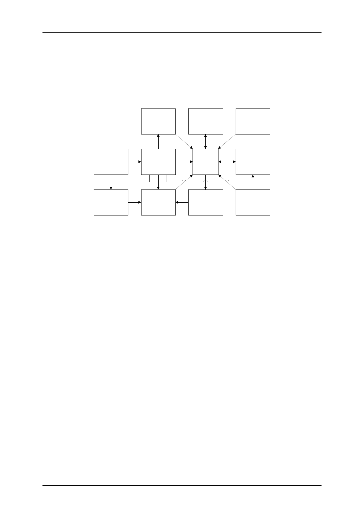
The following block diagram shows the main function blocks of the LC display module:
Voltage
regulation
uC
LCD
Operation
Programming
interface
LC module bus
Scale
service
Switch
on/off
logics
Display representation
A maximum of five digits as well as some special characters can be displayed, which can appear as
shown below:
Explanation of the special characters:
Symbol Meaning
Battery Battery warning, operation of the scale can continue, but the batteries
should be replaced. If the batteries are not replaced and are allowed to
discharge below the next threshold, the ”bAtt“ message is displayed.
Measurements are then no longer possible.
Measuring range 1 Measuring range 1 is active.
Measuring range 2 Measuring range 2 is active.
Power supply unit The scale is operating in power supply unit mode.
PT PT indicates that a weight value previously saved will automatically be
subtracted from the weight value currently measured.
BMI The BMI function is active. Once body height has been entered, the BMI
value is displayed.
Service Manual Description of the LC2 electronics
23.07.07 Kr/Rei Page 2(6) 30-34-00-745
Hold + warning
triangle
Hold indicates that the weight display has frozen. The warning triangle
signals that the weight displayed on the scale is not verifiable.
TARE, NET Tare or Net show that a weight on the scale has been tared out.
cm The value displayed corresponds to body height in cm. (BMI)
lbs The weight value is displayed in lbs.
kg The weight value is displayed in kg.
sts The weight value is displayed in lbs and sts.
Power supply
Power supply is provided via the LC module bus. The power supply for the display module is
connected through the start button. Once the microcontroller on the LC display module has started, it
assumes control of the power supply. When the start button is pressed again, the power supply to the
display is switched off.
Operation
With the exception of the start button (if provided), the connected buttons can be configured as
required for the particular model. These buttons can be pressed just lightly or longer (longer than 1 s).
Scale service
To activate scale service, 2 contact pins on the PCB must be short-circuited by means of a
jumper/switch. Access to these contacts can only be gained by destroying the seal and opening the
display housing. After placing the jumper, switch on the scale to start scale service.
LC module bus
The LC module bus establishes the connection to the LC weight module. The unregulated supply
voltage from the LC weight module is available on the bus. All relevant data is exchanged via a data
line and a clock pulse line.
Pin Function Note
1 SCL Serial Clock TWI
2 GND Ground
3 SDA Serial Data TWI
4 Vin Battery/power supply voltage
Programming interface
The programming interface is a 10-pin interface, which is only accessible after opening the display
housing. The display housing is secured with a seal that must be destroyed to open the housing.
Warning: If the seal is destroyed, verification is no longer valid. A special seca service adapter is
required to access the programming interface.
The service interface can be used to:
- supply the unregulated supply voltage
- measure the regulated voltage for the electronics
- execute the start function
- delete and write new data to the flash memory and the EEPROM of the microcontroller
Programming
The microcontroller contains two types of non-volatile memories that are used for various purposes in
the module.
The following memory types are provided:
Service Manual Description of the LC2 electronics
23.07.07 Kr/Rei Page 3(6) 30-34-00-745
Type of memory Size
Flash memory 8 Kbytes
EEPROM 512 bytes
The flash memory holds the firmware for the microcontroller. During programming, the data is written
to the flash memory via the 10-pin programming interface. The parameters read out by the LC display
module from the LC weight module after being set into operation for the very first time are stored in the
EEPROM. Both memories are protected by an LRC checksum. A data error in either of the two
memories cannot be remedied during the operation and causes a permanent fault indication.
Weighing operations are then no longer possible. Once the scale has been programmed, both
memories are protected against reading out and modifying data via the programming interface. Any
modification of the data first requires that both memories are completely cleared.
Fault handling
If faults occur, they are displayed on the LCD with the relevant fault code. Each fault message
includes the number of the module type on which the fault has occurred.
Module Number
LC weight module 10
LC display module 11
The following fault messages are implemented:
Fault number Fault description
11 Outside value range (positive or negative overload)
12 Switch-on zero point outside the permissible range
13 Zero follow-up outside the permissible range
16 No zero point
40 EEPROM checksum fault
50 Flash memory checksum fault
60 Bus communication fault
Technical data
Supply voltage : 9V – 12V (via LC module bus)
Supply current: typ. 11.8mA
Zero-signal current: typ. < 0.1µA
Operating temperature: approx. 0°C to 50°C
Storage temperature: -10°C to 60°C
Dimensions: 63mm x 42mm x 1.7mm
Service Manual Description of the LC2 electronics
23.07.07 Kr/Rei Page 4(6) 30-34-00-745
Brief description of the LC weight module
Introduction
The LC weight module is used to determine weights using one or several load cell(s) with strain
gauges. The LC module bus supplies the processed measured values to the LC display module.
The following block diagram shows the main function blocks of the LC weight module:
Voltage
regulation
uC
Voltage
measurement
A/D converter
Programming
interface
LC module bus
Switch
on/off
logics
Load cell(s)
Temperature
measurement
Resonator
Mains
connection
/battery
Weight measurement
The weight module uses load cells with strain gauges in a double bridge circuit as sensors. The entire
analog part and the load cells, as well as the other peripherals, are supplied with a 5V supply voltage.
At full load, the load cells supply a bridge output voltage of 0.8mV/V. This voltage is measured by a
dual slope A/D converter; the different voltages supplied by the four load cells are multiplexed
accordingly. Every 500 ms, 12 measurements are carried out per load cell and the mean value is then
calculated. Before the mean values for each load cell are merged and converted into the weight value,
an individual corner correction factor is applied to them. A linear function is used to convert the results
into a weight value. The first stable value within the switch-on zero setting range after switching on the
scale is used as zero point. The zero follow-up range is monitoring during the operation of the scale.
Temperature measurement
In order to compensate for the load cell’s temperature drift, the temperature is measured regularly and
the measured value is adjusted accordingly. For this measurement, the voltage is cyclically measured
via an NTC, which forms a voltage divider together with a linearization resistor connected in series. To
reduce measured value fluctuations, a mean value of 8 temperature values is always formed.
Fluctuations are thus reduced to a third compared with individual measurements. The difference
between the current temperature and the temperature measured when the last zero point was
obtained is used to determine a projected zero point. To do so, one assumes that the weight change
per °C is constant. The weight value is then corrected in accordance with the zero point calculated and
in accordance with the difference to the temperature measured when the scale was adjusted.
Power supply
Power supply can be provided by AA size batteries or a power supply unit. The circuit cannot be
operated on rechargeable batteries. The unregulated voltage is connected to a 5V in-phase regulator
via reverse voltage protection diodes. The regulated 5V supply voltage is then available to the entire
circuit. The supply voltage for the analog part can be switched separately from the rest of the PCB via
a switch on/off logic. The digital part is permanently supplied with 5V.
Voltage measurement
To enable power supply unit and battery operation to be distinguished and in order to measure the
current battery voltage, the unregulated voltage is monitored by the microcontroller. Voltage
measurement takes place via a voltage divider and by means of the internal A/D converter.
 Loading...