


Service Manual
for seca |
334 LC / 335 LC |
|
Variants: |
|
|
3341321008 |
|
|
3341321368 |
|
|
3357021094 |
Service Manual Number |
|
3357021129 |
||
17-05-01-342-b |
||
3357021159 |
Description: |
Valid as of: 01.04.2013 |
|
|
Baby scale with 4 load cell technology |
|
When servicing or repairing seca devices according to this service manual, always take note of the instruction manual of the product. To download the latest version of the instruction manual and EMC Recommendation go to www.seca.com.
Contents:
Description electronic |
30-34-00-864 |
Cableplan |
08-02-06-036 a |
Replacement |
30-34-00-752 a |
Spare parts |
334 1321008 |
Spare parts |
334 1321368 |
Spare parts |
335 7021159 |
Spare parts drawing |
30-34-00-749 b |
EMC Recommendation |
30-35-00-219 |
Instruction manual mod. 334 LC |
17-10-06-335 |
Instruction manual mod. 335 LC |
17-10-07-552 |
Instruction manual mod. 335 LC China |
17-10-07-555 |
Manual number: 17-05-01-342-b
Service Instructions LC Electronics |
seca |
Service Instructions Electronics (LC)
MODEL
[334|335|382|383|384|385|769|799|780|833|834|835|869|899|874|
875|876|877|878|952|956]
03.04.2013/JEG |
1 (24) |
30-34-00-864 |
Contents |
seca |
Contents
1 |
General Information....................................................................................................................... |
3 |
||
|
1.1 |
Rating plates..................................................................................................................... |
3 |
|
|
1.2 |
Structure and function of scale section ............................................................................ |
4 |
|
|
|
1.2.1 |
Structure .............................................................................................................. |
4 |
|
|
1.2.2 |
Function ............................................................................................................... |
4 |
2 |
Calibration of Scales ..................................................................................................................... |
6 |
||
|
2.1 |
Manual calibration of scale [334|335|382|383|384|385|833|834|835] .............................. |
6 |
|
|
2.2 |
Manual calibration of scale [874|875|876|877|878|952|956] ............................................ |
9 |
|
|
2.3 |
Manual calibration of scale [769|780|799|869|899]........................................................ |
11 |
|
|
|
2.3.1 |
Linear calibration ............................................................................................... |
11 |
|
|
2.3.2 |
Calibration of corner loading.............................................................................. |
13 |
3 |
Troubleshooting........................................................................................................................... |
15 |
||
|
3.1 |
Error symptoms scale..................................................................................................... |
15 |
|
|
3.2 |
Scale error messages..................................................................................................... |
16 |
|
3.3Error messages [334|335|382|383|384|385|833|834|835|874|875|876|877|878|952|956]16
|
3.4 |
Error messages [769|799|780|869|899] ......................................................................... |
17 |
|
4 |
Measurements for Fault Localisation .......................................................................................... |
19 |
||
|
4.1 |
Power supply .................................................................................................................. |
19 |
|
|
4.2 |
Load cell ......................................................................................................................... |
19 |
|
|
|
4.2.1 |
Testing load cells with a multimeter................................................................... |
19 |
5 |
Replacing Electronics.................................................................................................................. |
21 |
||
6 |
Appendices |
.................................................................................................................................. |
23 |
|
03.04.2013/JEG |
2 (24) |
30-34-00-864 |

General Information |
seca |
1 General Information
These service instructions are for technicians responsible for the maintenance and repair of devices. These persons must be familiar with all regulations governing electrical engineering and comply with them in all cases. These instructions are not intended for users without specialist skills.
These instructions describe servicing for the devices [334|335|382|383|384|385|769|799| 780|833|834|835|869|899|874|875|876|877|878|952|956]. The individual sections indicate the devices to which they apply in each case.
1.1Rating plates
To identify the exact model see the information and serial number on the underside or base frame of the device (see Figure 1). Please take note of this data so you have it to hand when making queries or ordering spare parts.
Figure 1: Rating plates
03.04.2013/JEG |
3 (24) |
30-34-00-864 |

General Information |
seca |
1.2 Structure and function of scale section
1.2.1 Structure
The scale basically consists of the following parts:
Base frame with up to four load cells
Display unit with keypad
Power supply (batteries, optional power pack)
.
1.2.2 Function
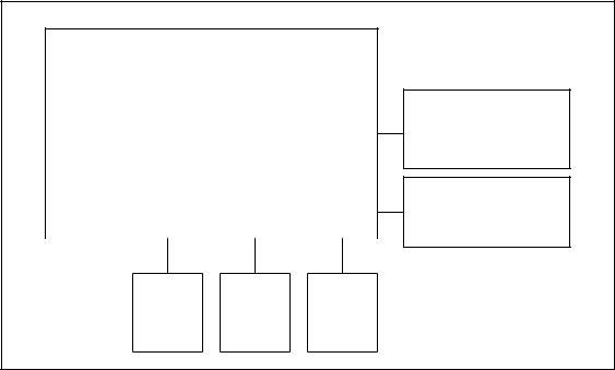
The effect of weight on the weighing surface causes elastic deformation of the load cell(s) underneath. They produce an electronic analogue signal which shows linear variation in relation to the application of force. This signal is measured by the weight calculation system, analysed and displayed as a weighing value. Figure 2 shows the function chart for scales with separate electronic modules for weight calculation and display. Figure 3 shows the function chart for scales with one electronic module for weight calculation and display.
LCD module 08-06-18-147
(Modular cable)
LC weight calculation
08-06-18-149
|
|
|
|
|
|
|
|
|
|
|
Load |
|
Load |
|
Load |
|
Load |
||||
cell |
|
cell |
|
cell |
|
cell |
||||
|
|
|
|
|
|
|
|
|
|
|
Keypad
DC power
Figure 2: Function chart [769|799|780|869|899]
03.04.2013/JEG |
4 (24) |
30-34-00-864 |
General Information |
seca |
LC compact modules (weight |
|
calculation and display) |
|
08-06-18-142 or 08-06-18-160 |
Keypad |
DC supply
|
|
|
|
|
|
|
|
Load |
|
Load |
|
Load |
|
Load |
|
cell |
|
cell |
|
cell |
|
cell |
|
|
|
|
|
|
|
|
|
Figure 3: Function chart [334|335|382|383|384|385|833|834|835|874|875|876|877|878|952|956]
03.04.2013/JEG |
5 (24) |
30-34-00-864 |

Calibration of Scales |
seca |
2 Calibration of Scales
The scale is equipped with a calibration option to compensate for linear measurement errors as for example, those occurring with geographical variation in the earth's gravitational force. This calibration procedure must also be carried out whenever a load cell is replaced.
Calibration can be performed in one of two ways:
The scales are equipped with an internal manual calibration feature, which is regulated by the control elements on the device.
Calibration is performed with the help of seca serva
2.1Manual calibration of scale [334|335|382|383|384|385|833|834|835]
Manual calibration is activated by plugging a jumper on the printed circuit board (see Figure 4). These contacts are only accessible after breaking the seal and opening the scale. After plugging the jumper, the scale has to be switched on to start manual calibration.
Figure 4: Jumper contacts to activate manual calibration
03.04.2013/JEG |
6 (24) |
30-34-00-864 |
Calibration of Scales |
seca |
The following steps are necessary to perform manual calibration of the scale:
1.Switch on the scale and check the battery charge (see note). Calibration must not continue if the batteries are low!
2.Then switch the scale off and unscrew the lower service lid after having removed the seal.
3.Connect the two jumper contacts using a jumper.
4.Then set up the scale properly again and switch on.
5.Start-up of the scale is followed by the segment test and then a flashing display showing the weight to be placed on the scale.
6.Place the calibrated weight in the middle of the weighing surface in one, or at most two steps of equal size. The calibration weight required may vary depending on the model (see Table 1).
Model |
Calibration weight |
|
|
335, 382, 384 |
10 kg |
|
|
334, 384, 833, 834 |
15 kg |
|
|
835 |
20 kg |
|
|
383, 385 |
40 kg |
|
|
Table 1: Calibration weights required
7.Once a correct, stable weight value is identified, the LCD display will stop flashing, and a calibration value will be calculated and stored. The scale then switches off automatically shortly afterwards. If the LCD display does not stop flashing, the measured weight is either above or below the weight to be expected, or a stable weight value cannot be established (due to vibration / shocks, etc.).
03.04.2013/JEG |
7 (24) |
30-34-00-864 |
Calibration of Scales |
seca |
8.Then remove the weight from the scale, detach the jumper from the
PCB and replace the service lid.
9.Now set up the scale again and switch on. Next, place a calibrated weight on the scale and check the display for the correct weight value. If manual calibration was successful, reseal the service lid according to the national regulations.
Note:
Automatic monitoring of the battery voltage is not possible during manual calibration. It should therefore be checked before and after every calibration procedure. This can be carried out by switching on the scale and observing the display. If the battery voltage is insufficient, either the battery warning symbol or the "bAtt" display will be activated. If one of these displays appears before or immediately after calibration, the batteries should be replaced and the calibration procedure repeated.
Manual calibration can be aborted before placing the required weight on the scale by switching off the device.
03.04.2013/JEG |
8 (24) |
30-34-00-864 |
Calibration of Scales |
seca |
2.2Manual calibration of scale [874|875|876|877|878|952|956]
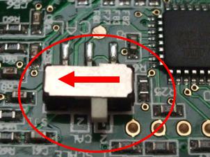
Manual calibration is activated using a sliding switch (SJ1) on the PCB (see Figure 5). It is only accessible after breaking the seal and opening the scale. After changing the switch position to 2 ("CAL"), the scale has to be switched on to start manual calibration.
Figure 5: Slide switch to activate manual calibration
The following steps are necessary to perform manual calibration of the scale:
1.Switch on the scale and check the battery charge (see note). Calibration must not continue if the batteries are low!
2.Then switch the scale off and open the integrated display by releasing the four screws after having removed the seals.
3.The position 2 ("CAL") must be selected with the slide switch on the
PCB, which is now accessible.
4.Then set up the scale properly and switch on.
5.Start-up of the scale is followed by the segment test and then a flashing display showing the weight to be placed on the scale.
03.04.2013/JEG |
9 (24) |
30-34-00-864 |
Calibration of Scales |
seca |
6.Place the calibrated weight in the middle of the weighing surface in one, or at most two steps of equal size. The calibration weight required may vary depending on the model (see Table 2).
Model |
Calibration weight |
874, 875, 876, 877, 878,
120 kg
952, 956
Table 2: Calibration weights required
7.Once a correct, stable weight value is identified, the LCD display will stop flashing, and a calibration value will be calculated and stored. The scale then switches off automatically shortly afterwards. If the LCD display does not stop flashing, the measured weight is either above or below the weight to be expected, or a stable weight value cannot be established (due to vibration / shocks, etc.).
8.Then remove the weight from the scale, move the slide switch on the PCB back to its original position and refit the display.
9.Now set up the scale again and switch on. Next, place a calibrated weight on the scale and check the display for the correct weight value. If manual calibration was successful, reseal the scale according to the national regulations.
Note:
Automatic monitoring of the battery voltage is not possible during manual calibration. It should therefore be checked before and after every calibration procedure. This can be carried out by switching on the scale and observing the display. If the battery voltage is insufficient, either the battery warning symbol or the "bAtt" display will be activated. If one of these displays appears before or immediately after calibration, the batteries should be replaced and the calibration procedure repeated.
Manual calibration can be aborted before placing the required weight on the scale by switching off the device.
03.04.2013/JEG |
10 (24) |
30-34-00-864 |
 Loading...